CN103329413A - Power conversion apparatus - Google Patents
Power conversion apparatusDownload PDFInfo
- Publication number
- CN103329413A CN103329413ACN2012800054706ACN201280005470ACN103329413ACN 103329413 ACN103329413 ACN 103329413ACN 2012800054706 ACN2012800054706 ACN 2012800054706ACN 201280005470 ACN201280005470 ACN 201280005470ACN 103329413 ACN103329413 ACN 103329413A
- Authority
- CN
- China
- Prior art keywords
- voltage
- motor
- power
- conversion device
- power conversion
- Prior art date
- Legal status (The legal status is an assumption and is not a legal conclusion. Google has not performed a legal analysis and makes no representation as to the accuracy of the status listed.)
- Granted
Links
Images


Classifications
- H—ELECTRICITY
- H02—GENERATION; CONVERSION OR DISTRIBUTION OF ELECTRIC POWER
- H02P—CONTROL OR REGULATION OF ELECTRIC MOTORS, ELECTRIC GENERATORS OR DYNAMO-ELECTRIC CONVERTERS; CONTROLLING TRANSFORMERS, REACTORS OR CHOKE COILS
- H02P29/00—Arrangements for regulating or controlling electric motors, appropriate for both AC and DC motors
- H02P29/50—Reduction of harmonics
- H—ELECTRICITY
- H02—GENERATION; CONVERSION OR DISTRIBUTION OF ELECTRIC POWER
- H02M—APPARATUS FOR CONVERSION BETWEEN AC AND AC, BETWEEN AC AND DC, OR BETWEEN DC AND DC, AND FOR USE WITH MAINS OR SIMILAR POWER SUPPLY SYSTEMS; CONVERSION OF DC OR AC INPUT POWER INTO SURGE OUTPUT POWER; CONTROL OR REGULATION THEREOF
- H02M1/00—Details of apparatus for conversion
- H02M1/12—Arrangements for reducing harmonics from AC input or output
- H—ELECTRICITY
- H02—GENERATION; CONVERSION OR DISTRIBUTION OF ELECTRIC POWER
- H02P—CONTROL OR REGULATION OF ELECTRIC MOTORS, ELECTRIC GENERATORS OR DYNAMO-ELECTRIC CONVERTERS; CONTROLLING TRANSFORMERS, REACTORS OR CHOKE COILS
- H02P21/00—Arrangements or methods for the control of electric machines by vector control, e.g. by control of field orientation
- H02P21/05—Arrangements or methods for the control of electric machines by vector control, e.g. by control of field orientation specially adapted for damping motor oscillations, e.g. for reducing hunting
Landscapes
- Engineering & Computer Science (AREA)
- Power Engineering (AREA)
- Control Of Ac Motors In General (AREA)
- Inverter Devices (AREA)
- Ac-Ac Conversion (AREA)
Abstract
Translated fromChinese
Description
Translated fromChinese技术领域technical field
本发明涉及一种利用开关将所输入的电转换成规定电的功率转换装置。The present invention relates to a power conversion device that converts input power into predetermined power by using a switch.
背景技术Background technique
在用于空调机的电动压缩机等的马达中,有时在该马达的感应电压中包含为基频的5倍的分量或7倍的分量等谐波分量(harmonic component)。在现有技术的控制下,对向马达供电的直交流转换电路进行控制,使得流经马达的相电流成为正弦波。然而,在该控制下,有可能出现在马达电压失真的影响下使马达电流失真而产生转矩波动等问题。In motors such as electric compressors used in air conditioners, the induced voltage of the motor may contain harmonic components such as components five times or seven times the fundamental frequency. Under the control of the prior art, the DC-AC conversion circuit that supplies power to the motor is controlled so that the phase current flowing through the motor becomes a sine wave. However, under this control, there is a possibility that the motor current is distorted under the influence of the motor voltage distortion to generate torque ripple.
因此,提出了下述技术,即:预先在表格中准备抵消马达的转矩波动的补偿电压分量,将该补偿电压加在电压指令上,由此来减小转矩波动(参照例如专利文献2)。Therefore, a technique has been proposed in which a compensation voltage component for canceling torque fluctuations of the motor is prepared in advance in a table, and the compensation voltage is added to a voltage command to reduce torque fluctuations (see, for example, Patent Document 2 ).
另一方面,在像所谓的无电容器型直交流转换器(参照例如专利文献1)那样在内部不具有储能元件的直交流转换器中,若产生转矩波动,则在输入直交流转换器的能量中也会包含该谐波分量,因而会产生无法满足所制定的电源谐波限制(power-supplyharmonic regulation)(在此,电源谐波指的是输入电流中所包含的谐波)的问题。因此,提出了一种通过对马达电流的谐波分量另加控制来减小电流失真或转矩波动的技术(参照例如专利文献3)。On the other hand, in a DC converter that does not have an internal energy storage element like a so-called capacitorless DC converter (see, for example, Patent Document 1), if torque ripple occurs, the input DC converter The harmonic component will also be included in the energy of the power supply, so there will be a problem that the power-supply harmonic regulation (power-supplyharmonic regulation) (here, the power supply harmonic refers to the harmonic contained in the input current) cannot be satisfied. . Therefore, there has been proposed a technique for reducing current distortion or torque ripple by additionally controlling the harmonic components of the motor current (see, for example, Patent Document 3).
专利文献1:日本公开特许公报特开2002-51589号公报Patent Document 1: Japanese Laid-Open Patent Publication No. 2002-51589
专利文献2:日本公开特许公报特开2008-219966号公报Patent Document 2: Japanese Laid-Open Patent Publication No. 2008-219966
专利文献3:日本公开特许公报特开2006-262700号公报Patent Document 3: Japanese Patent Application Laid-Open No. 2006-262700
发明内容Contents of the invention
-发明所要解决的技术问题--The technical problem to be solved by the invention-
然而,在像专利文献2的示例那样使用预先在表格中准备的补偿电压进行补偿时,存在所应补偿的电压由于马达的运转状态(转速或负载转矩等)产生误差,而无法减小电流失真或转矩波动的情况。However, when compensation is performed using a compensation voltage prepared in advance in a table as in the example of Patent Document 2, there is an error in the voltage to be compensated depending on the operating state of the motor (rotational speed, load torque, etc.), and the current cannot be reduced. Distortion or torque ripple conditions.
本发明正是鉴于所述问题而完成的,其目的在于:在功率转换装置中,能够根据马达的运转状态(转速或负载转矩等)降低起因于马达电压失真的电源谐波。The present invention was made in view of the above problems, and an object of the present invention is to reduce power supply harmonics caused by motor voltage distortion according to the operating state of the motor (rotational speed, load torque, etc.) in a power conversion device.
-用以解决技术问题的技术方案--Technical solutions to solve technical problems-
为了解决上述问题,第一方面的发明涉及一种功率转换装置,其包括开关元件Su、Sv、Sw、Sx、Sy、Sz,经功率转换将已由交流电源6供给的输入交流电转换成具有规定电压和规定频率的输出交流电后,供给所连接的马达7,其特征在于:该功率转换装置包括控制部5、电容器3a、电流控制部53及电压失真补正部54,控制部5对所述开关元件Su、Sv、Sw、Sx、Sy、Sz的开关进行控制,电容器3a对由于所述开关元件Su、Sv、Sw、Sx、Sy、Sz的开关而产生的波动进行平滑,电流控制部53对流向所述马达7的电流进行控制,电压失真补正部54对起因于马达输入功率失真的谐波分量进行检测,并根据所述谐波分量的值将补偿值vd_h、vq_h叠加在所述电流控制部53的输出上。In order to solve the above-mentioned problems, the invention of the first aspect relates to a power conversion device, which includes switching elements Su, Sv, Sw, Sx, Sy, Sz, and converts the input AC power supplied by the
在该结构下,因为根据起因于马达输入功率失真的谐波分量将补偿值叠加在电流控制部53的输出上,所以能够使马达的输入功率、电源一侧的电流、功率及直流链电压不产生失真。With this structure, since the compensation value is superimposed on the output of the
第二方面的发明是这样的,在第一方面的发明所涉及的功率转换装置中,其特征在于:所述电压失真补正部54从输入所述马达7的输入功率中提取所述谐波分量。The second aspect of the invention is that, in the power conversion device according to the first aspect of the invention, the voltage
在该结构下,控制部5对输入功率的失真进行实际检测,并根据检测到的失真情况对所述补偿电压vd_h、vq_h进行补正。Under this structure, the
第三方面的发明是这样的,在第一方面的发明所涉及的功率转换装置中,其特征在于:所述电压失真补正部54从所述电容器3a的电压中提取所述谐波分量。The invention of claim 3 is such that, in the power conversion device according to the invention of claim 1 , the voltage
在该结构下,从电容器3a的电压中提取谐波分量。为此,很容易就能够掌握谐波分量的大小。Under this structure, harmonic components are extracted from the voltage of the
第四方面的发明是这样的,在第一方面的发明所涉及的功率转换装置中,其特征在于:所述电压失真补正部54从输入功率转换装置的输入电流中提取所述谐波分量。A fourth aspect of the invention is that, in the power conversion device according to the first invention, the voltage
在该结构下,从输入电流中提取谐波分量。Under this structure, harmonic components are extracted from the input current.
第五方面的发明是这样的,在第二至第四方面中的任一方面的发明所涉及的功率转换装置中,其特征在于:所述电压失真补正部54在所述交流电源6的半周期的整数倍的期间进行傅里叶变换,提取所述谐波分量。The fifth aspect of the invention is that, in the power conversion device according to any one of the second to fourth aspects of the invention, it is characterized in that the voltage
在该结构下,利用傅里叶变换提取谐波分量。为此,能够准确地掌握谐波分量的大小。在该结构下,通过使进行傅里叶变换的周期成为交流电源6的半周期的整数倍,从而能够适当地提取所希望的频率分量。Under this structure, harmonic components are extracted using Fourier transform. For this reason, it is possible to accurately grasp the magnitude of the harmonic component. With this configuration, a desired frequency component can be appropriately extracted by setting the cycle for performing Fourier transform to an integer multiple of the half cycle of the
第六方面的发明是这样的,在第二至第五方面中的任一方面的发明所涉及的功率转换装置中,其特征在于:所述电压失真补正部54根据使所述补偿值vd_h、vq_h产生变化之前和之后的所述谐波分量的增减情况,对所述补偿值vd_h、vq_h进行调整。A sixth aspect of the invention is that, in the power conversion device according to any one of the second to fifth aspects of the invention, the voltage
在该结构下,利用所谓的爬山法来调整补偿电压vd_h、vq_h。With this configuration, the compensation voltages vd_h, vq_h are adjusted by the so-called hill-climbing method.
第七方面的发明是这样的,在第二至第六方面中的任一方面的发明所涉及的功率转换装置中,其特征在于:所述补偿值vd_h、vq_h具有所述马达7之电压的基频的6n倍的频率分量,n为整数。The seventh aspect of the invention is as follows. In the power conversion device according to any one of the second to sixth aspects of the invention, it is characterized in that: the compensation values vd_h, vq_h have the voltage of the motor 7 Frequency components that are 6n times the fundamental frequency, where n is an integer.
在该结构下,能够对补偿电压vd_h、vq_h进行设定,以降低较大的谐波分量。在该结构下,很容易就能够调整补偿电压vd_h、vq_h。With this configuration, the compensation voltages vd_h and vq_h can be set so as to reduce large harmonic components. With this configuration, it is easy to adjust the compensation voltages vd_h, vq_h.
第八方面的发明是这样的,在第二至第七方面中的任一方面的发明所涉及的功率转换装置中,其特征在于:所述电压失真补正部54根据所述马达7的转速、转矩及功率中的任一者对所述补偿值vd_h、vq_h的振幅进行调整。The invention of claim 8 is such that, in the power conversion device according to any one of the inventions of claims 2 to 7, it is characterized in that the voltage
在该结构下,经由调整补偿电压vd_h、vq_h的振幅,来调整功率转换装置的输出电压。In this configuration, the output voltage of the power conversion device is adjusted by adjusting the amplitudes of the compensation voltages vd_h and vq_h.
第九方面的发明是这样的,在第二至第七方面中的任一方面的发明所涉及的功率转换装置中,其特征在于:所述电压失真补正部54对所述补偿值vd_h、vq_h的相位和振幅中的至少一者进行调整。The invention of claim 9 is such that, in the power conversion device according to any one of the inventions of claims 2 to 7, it is characterized in that the voltage
在该结构下,经由调整补偿电压vd_h、vq_h的相位或者振幅,来调整功率转换装置的输出电压。Under this configuration, the output voltage of the power conversion device is adjusted by adjusting the phase or amplitude of the compensation voltages vd_h and vq_h.
第十方面的发明是这样的,在第一至第九方面中的任一方面的发明所涉及的功率转换装置中,其特征在于:所述功率转换装置包括对所述输入交流电进行全波整流的交直流转换电路2,所述电容器3a与所述交直流转换电路2的输出侧并联,构成直流链部3,并输出脉动的直流电压vdc,所述开关元件Su、Sv、Sw、Sx、Sy、Sz构成直交流转换电路4,并利用开关将所述直流链部3的输出转换成交流电后供给所述马达7,所述控制部5对所述开关进行控制,使得所述马达7的电流iu、iv、iw与所述电源电压vin的脉动同步地脉动。The tenth aspect of the invention is as follows. In the power conversion device according to any one of the first to ninth aspects of the invention, it is characterized in that: the power conversion device includes full-wave rectification of the input alternating current The AC-DC conversion circuit 2, the
在该结构下,在所谓的无电容器型直交流转换电路中,对补偿电压vd_h、vq_h进行调整,使得电源一侧所包含的谐波分量降低。With this configuration, in a so-called capacitorless DC-AC conversion circuit, the compensation voltages vd_h and vq_h are adjusted so that harmonic components included on the power supply side are reduced.
-发明的效果--Effects of the invention-
根据第一方面的发明,在功率转换装置中,能够根据马达的运转状态降低起因于马达电压失真的电源谐波。According to the first aspect of the invention, in the power conversion device, it is possible to reduce power supply harmonics caused by distortion of the motor voltage in accordance with the operating state of the motor.
在第二方面或者第三方面的发明中,很容易就能够掌握谐波分量的大小。In the invention of the second aspect or the third aspect, it is easy to grasp the magnitude of the harmonic component.
在第四方面的发明中,因为能够直接地对电源谐波限制的对象即输入电流的谐波分量进行检测,所以能够更有效地降低电源谐波。In the fourth aspect of the invention, since it is possible to directly detect the harmonic component of the input current which is the subject of power supply harmonic restriction, it is possible to more effectively reduce the power supply harmonics.
根据第五方面的发明,因为能够准确地掌握所希望的谐波分量的大小,所以能够更可靠地降低所述电源谐波。According to the fifth aspect of the invention, since the magnitude of the desired harmonic component can be accurately ascertained, the power supply harmonic can be reduced more reliably.
根据第六方面的发明,因为能够设定适当的补偿电压vd_h、vq_h,所以能够更可靠地降低所述电源谐波。According to the sixth aspect of the invention, since appropriate compensation voltages vd_h and vq_h can be set, the power supply harmonics can be reduced more reliably.
根据第七方面的发明,因为能够对补偿电压vd_h、vq_h进行设定,以降低较大的谐波分量,所以能够更有效地降低所述电源谐波。According to the seventh aspect of the invention, since the compensation voltages vd_h and vq_h can be set to reduce large harmonic components, the power supply harmonics can be reduced more effectively.
根据第八方面的发明,仍能防止马达的输入功率、电源一侧的电流、功率及直流链电压产生失真。According to the invention of the eighth aspect, the distortion of the input power of the motor, the current of the power supply side, the power and the DC link voltage can still be prevented.
根据第九方面的发明,能够更准确地防止马达的输入功率、电源一侧的电流、功率及直流链电压产生失真。According to the ninth aspect of the invention, it is possible to more accurately prevent distortion of the input power of the motor, the current and power on the power supply side, and the DC link voltage.
根据第十方面的发明,在所谓的无电容器型直交流转换电路中,能够降低起因于马达电压失真的电源谐波。According to the tenth aspect of the invention, in the so-called capacitorless DC/AC conversion circuit, it is possible to reduce power supply harmonics caused by motor voltage distortion.
附图说明Description of drawings
图1是表示本发明的实施方式所涉及的功率转换装置的结构的方框图。FIG. 1 is a block diagram showing the configuration of a power conversion device according to an embodiment of the present invention.
图2是表示控制部的结构示例的方框图。FIG. 2 is a block diagram showing a configuration example of a control unit.
图3是表示电流指令生成部的结构示例的方框图。FIG. 3 is a block diagram showing a configuration example of a current command generation unit.
图4是表示谐波分量除去部的结构示例的方框图。FIG. 4 is a block diagram showing a configuration example of a harmonic component removing unit.
图5是表示电压失真补正部的结构示例的方框图。FIG. 5 is a block diagram showing an example configuration of a voltage distortion correction unit.
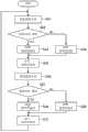
图6是说明电压失真补正部所进行的补偿电压动作的流程图。6 is a flowchart illustrating a voltage compensation operation performed by a voltage distortion correction unit.
图7的(A)是表示在没有叠加补偿电压的情况下马达的输入功率、U相的相电压、马达电流的波形图。图7的(B)是表示在已叠加了补偿电压的情况下输入功率、相电压、马达电流的波形图。(A) of FIG. 7 is a waveform diagram showing the input power of the motor, the phase voltage of the U-phase, and the motor current when the compensation voltage is not superimposed. (B) of FIG. 7 is a waveform diagram showing input power, phase voltage, and motor current when the compensation voltage is superimposed.
图8是表示矩阵交-交转换器的结构示例的方框图。Fig. 8 is a block diagram showing a configuration example of a matrix AC-AC converter.
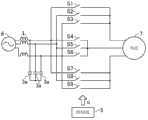
图9是表示将三相交流电源用作交流电源时的功率转换装置的结构示例的方框图。FIG. 9 is a block diagram showing a configuration example of a power conversion device when a three-phase AC power source is used as the AC power source.
具体实施方式Detailed ways
下面,参照附图对本发明的实施方式进行说明。此外,以下实施方式是本质上优选的示例,并没有意图对本发明、其应用对象或其用途的范围加以限制。Hereinafter, embodiments of the present invention will be described with reference to the drawings. In addition, the following embodiments are preferred examples per se, and are not intended to limit the scope of the present invention, its application objects, or its uses.
(整体结构)(the whole frame)
图1是表示本发明的实施方式所涉及的功率转换装置1的结构的方框图。如图1所示,功率转换装置1包括:交直流转换电路2、直流链部3、直交流转换电路4及控制部5,将由单相交流电源6供给的交流电转换成规定频率的电后供给马达7。FIG. 1 is a block diagram showing the configuration of a power conversion device 1 according to an embodiment of the present invention. As shown in Fig. 1, the power conversion device 1 includes: an AC-DC conversion circuit 2, a DC link part 3, a DC-
此外,本实施方式的马达7是三相交流马达,用以驱动设置在空调机的制冷剂回路中的压缩机。进一步具体而言,马达7是4极6槽集中绕组马达。在该马达7中,作为感应电压的谐波分量倾向于多包含基波的五次、七次分量。基于该马达电压失真的谐波分量也出现在电源电流及直流链电压(后述)中。In addition, the motor 7 of this embodiment is a three-phase AC motor for driving a compressor provided in a refrigerant circuit of an air conditioner. More specifically, the motor 7 is a concentrated winding motor with 4 poles and 6 slots. In this motor 7 , the harmonic components as the induced voltage tend to contain many fifth and seventh order components of the fundamental wave. Harmonic components due to the distortion of the motor voltage also appear in the power supply current and the DC link voltage (described later).
<交直流转换电路2><AC-DC conversion circuit 2>
交直流转换电路2经电抗器L与交流电源6相连,将交流电源6输出的交流电经全波整流成直流电。在该示例中,交直流转换电路2是由多个(在本实施方式中为四个)二极管D1~D4桥式连结而成的二极管电桥电路。这些二极管D1~D4将交流电源6的交流电压经全波整流而转换成直流电压。The AC-DC conversion circuit 2 is connected to the
<直流链部3><DC link part 3>
直流链部3包括电容器3a。电容器3a与交直流转换电路2的输出一侧并联,在该电容器3a的两端产生的直流电压(直流链电压vdc)与直交流转换电路4的输入节点连接。电容器3a由例如薄膜电容器构成。该电容器3a具有:在直交流转换电路4的开关元件(后述)进行开关动作时能够仅对与开关频率相对应着产生的波纹电压(电压波动)进行平滑的静电电容。也就是说,电容器3a是不具有能对已由交直流转换电路2整流过的电压(起因于电源电压的电压波动)进行平滑的静电电容的小电容电容器。为此,直流链部3输出的直流链电压vdc具有其最大值在其最小值的2倍以上的较大的脉动。The DC link section 3 includes a
<直交流转换电路4><DC-
直交流转换电路4的输入节点与直流链部3的电容器3a并联,该直交流转换电路4利用开关将直流链部3的输出转换成三相交流电后,供给所连接的马达7。本实施方式的直交流转换电路4由多个开关元件桥式连结而成。由于该直交流转换电路4将三相交流电向马达7输出,因而具有六个开关元件Su、Sv、Sw、Sx、Sy、Sz。具体而言,直交流转换电路4包括三个开关桥臂(switching leg),每个开关桥臂由两个开关元件彼此串联而成,在各个开关桥臂中上臂开关元件Su、Sv、Sw与下臂开关元件Sx、Sy、Sz之间的中点分别与马达7的各相中相对应的一相的线圈(省略图示)连接。续流二极管Du、Dv、Dw、Dx、Dy、Dz分别反并联在各个开关元件Su、Sv、Sw、Sx、Sy、Sz中相对应的一个开关元件上。直交流转换电路4利用这些开关元件Su、Sv、Sw、Sx、Sy、Sz的开关动作,经开关切换将已由直流链部3输入的直流链电压vdc转换成三相交流电压后,供向马达7。此外,对该开关动作的控制是由控制部5完成的。The input node of the DC-to-
<控制部5><
控制部5对直交流转换电路4中的开关(开关动作)进行控制,使得流向马达7的电流(马达电流iu、iv、iw)与电源电压vin的脉动同步地脉动。也就是说,功率转换装置1是所谓的无电容器型直交流转换器之一例。图2是表示控制部5的结构示例的方框图。在该示例中,控制部5包括:速度控制部50、电流指令生成部51、谐波分量除去部52、dq轴电流控制部53(在图中简单记作电流控制部)、电压失真补正部54及PWM运算部55。The
-速度控制部50--Speed control unit 50-
速度控制部50求出马达7的机械角的旋转角频率ωm与机械角的指令值ωm*之差,并对该差进行比例积分运算(PI运算)将转矩指令值T*向电流指令生成部51输出。The
-电流指令生成部51--Current command generator 51-
图3是表示电流指令生成部51的结构示例的方框图。如图3所示,该电流指令生成部51包括:基波分量运算部51a、绝对值运算部51b(在图3中简单记作abs)、输入电流控制部51c、dq电流指令值生成部51d、乘法器51e、51f以及加法器51g,向该电流指令生成部51输入转矩指令值T*、电源电压vin的相位角θin的正弦值sinθin及输入电流iin的绝对值|iin|。FIG. 3 is a block diagram showing a configuration example of the current
在该电流指令生成部51中,基波分量运算部51a在交流电源6的半周期的整数倍的期间进行傅里叶变换,从输入电流iin的绝对值中提取出电源电压的基波分量。这样一来,通过使进行傅里叶变换的周期成为交流电源6的半周期的整数倍,从而能够适当地提取所希望的频率分量。在该示例中,具体而言基波分量运算部51a求出sinθin与输入电流iin之积的平均值的2倍以作为第一值iin_1st。In this current
绝对值运算部51b求出sinθin的绝对值。乘法器51e用sinθin的绝对值乘以第一值iin_1st求出输入电流的绝对值的指令值|iin*|。The absolute value calculation unit 51b obtains the absolute value ofsinθin . The multiplier 51e multiplies the absolute value of sinθin by the first value iin_1st to obtain the command value |iin *| of the absolute value of the input current.
输入电流控制部51c生成指令值,使得输入电流iin的绝对值的指令值|iin*|与输入电流iin的绝对值|iin|之间的偏差减小。The input current control unit 51c generates the command value such that the deviation between the command value |iin *| of the absolute value of the input current iin and |iin | of the absolute value of the input current iin is reduced.
乘法器51f使sinθin的绝对值与转矩指令值T*相乘。该相乘的结果是以电源频率的两倍的频率脉动。该相乘所得的结果被输入加法器51g。加法器51g使乘法器51f的输出与输入电流控制部51c所输出的指令值相加。相加所得的结果作为电流指令值idq*被输入dq电流指令值生成部51d。The multiplier 51f multiplies the absolute value ofsinθin by the torque command value T*. The result of this multiplication is pulsating at twice the frequency of the power supply. The result of this multiplication is input to the adder 51g. The adder 51g adds the output of the multiplier 51f to the command value output from the input current control unit 51c. The result of the addition is input to the dq current command value generator 51d as the current command value idq*.
dq电流指令值生成部51d由电流指令值idq*与后述的电流相位指令值β*求出d轴电流指令值id*和q轴电流指令值iq*后,向谐波分量除去部52输出。具体而言,dq电流指令值生成部51d对电流指令值idq*乘以规定值β*的负的正弦值-sinβ*以生成d轴电流指令值id*,并对电流指令值idq*乘以规定值β*的余弦值cosβ*以生成q轴电流指令值iq*。在此,β*是流经马达7的电流的相位β的指令值。The dq current command value generating unit 51d obtains the d-axis current command value id* and the q-axis current command value iq* from the current command value idq* and the current phase command value β* described later, and outputs them to the harmonic
-谐波分量除去部52-- Harmonic component removal unit 52 -
谐波分量除去部52从所输入的信号中使基于马达电流失真的谐波分量减少。如图2所示,谐波分量除去部52设置在两个地方。在图2等中为了将两者区分开,在符号上附加了细分编号-1、-2。图4是表示谐波分量除去部52的结构示例的方框图。在图4中,举例示出与电流指令生成部51相连的谐波分量除去部52-1。电流指令值id*、iq*被输入谐波分量除去部52-1。此外,谐波分量除去部52-2与谐波分量除去部52-1的不同之处在于:向谐波分量除去部52-2输入的信号为电流指令值id’*、iq’*与实际电流值id、iq的差。The harmonic
在谐波分量除去部52-1中,在交流电源6的半周期的整数倍的期间进行傅里叶变换,从电流指令值id*、iq*中提取马达7的电压的六次分量。具体而言,谐波分量除去部52-1分别求出d轴电流指令值id*和sin6θ之积的平均值的2倍的值与d轴电流指令值id*和cos6θ之积的平均值的2倍的值,使前者所得到的值和sin6θ之积与后者所得到的值和cos6θ之积相加,将相加所得的结果作为d轴电流指令值id*的六次分量id_6th*。在此,θ是马达7的电压的基波分量的相位。谐波分量除去部52-1将从d轴电流指令值id*中减去六次分量id_6th*后所得到的值输出。也就是说,若设id*×sin6θ的平均值的2倍的值为id_sin6θ,设id*×cos6θ的平均值的2倍的值为id_cos6θ,则id_6th*能用下式表示。In the harmonic component removing unit 52 - 1 , Fourier transform is performed during a period that is an integral multiple of a half cycle of the
id_6th*=id_sin6θ×sin6θ+id_cos6θ×cos6θid_6th *=id_sin6θ×sin6θ+id_cos6θ×cos6θ
谐波分量除去部52-1使q轴电流指令值iq*和sin6θ之积与q轴电流指令值iq*和cos6θ之积相加,求出相加所得到的结果的平均值的2倍的值后,再求出该值和sin6θ的积与该值和cos6θ的积之和以作为q轴电流指令值iq*的六次分量iq_6th*。谐波分量除去部52-1将从q轴电流指令值iq*中减去六次分量iq_6th*后所得到的值输出。The harmonic component removing unit 52-1 adds the product of the q-axis current command value iq* and sin6θ to the product of the q-axis current command value iq* and cos6θ, and obtains the value twice the average value of the added results. After the value is obtained, the sum of the product of this value and sin6θ and the product of this value and cos6θ is obtained as the sixth-order component iq_6th * of the q-axis current command value iq*. The harmonic component removing unit 52-1 outputs a value obtained by subtracting the sixth-order componentiq_6th * from the q-axis current command value iq*.
此外,基于马达电流失真的谐波分量具有马达7之电压的基波频率(基频θ)的6n倍(n为整数)的频率分量。Further, the harmonic component based on the motor current distortion has a frequency component that is 6n times (n is an integer) the fundamental frequency (fundamental frequency θ) of the voltage of the motor 7 .
-dq轴电流控制部53-- dq-axis current control unit 53 -
dq轴电流控制部53是本发明的电流控制部之一例。dq轴电流控制部53生成电压指令值vd*、vq*,使得马达电流iu、iv、iw的指令值id’*、iq’*与实际电流值id、iq之间的偏差减小。dq轴电流控制部53具有比后述的补偿电压vd_h、vq_h的频率分量小的带宽。这是为了相对于基于马达电压失真的马达电流的谐波分量,使电流控制的响应变迟缓之故。The dq-axis
-电压失真补正部54--Voltage distortion correction unit 54-
在控制部5中,用补偿值(后述的补偿电压vd_h、vq_h)对输入直交流转换电路4的电压指令值vd*、vq*进行调整,使得包含在电源一侧的、基于马达电压失真的谐波分量(后述)降低。电压失真补正部54生成该补偿电压vd_h、vq_h。In the
图5是表示电压失真补正部54的结构示例的方框图。如图5所示,电压失真补正部54包括相位调整部54a、增益调整部54b及乘法器54c。电压失真补正部54提取出包含在直流链电压vdc中的感应电压之基波分量的6倍的频率(即,所述基频的6倍的频率)的信号(基于马达电压失真的谐波分量)。具体而言,电压失真补正部54对直流链电压vdc进行傅里叶变换而得到所述基频的6倍的频率分量。向电压失真补正部54输入该
在由增益调整部54b调整了
相位调整部54a检测出包含在直流链电压vdc中的马达电压的基波分量的6倍频率分量的相位δ,对该相位进行调整(后述)后输出。相位调整部54a的输出与6θ相加。由此,便得到6θ+δ。The
在电压失真补正部54中,求出-sin(6θ+δ)与电压振幅Vh的积以生成对d轴电压指令值vd*进行补正的d轴补偿电压vd_h。电压失真补正部54求出-cos(6θ+δ)与电压振幅Vh的积以生成对q轴电压指令值vq*进行补正的q轴补偿电压vq_h。在该示例中,各自的补偿电压vd_h、vq_h具有马达7之电压的基波频率(基频相位θ)的6n倍(n为整数)的频率分量。d轴补偿电压vd_h、q轴补偿电压vq_h分别与dq轴电流控制部53输出的d轴电压指令值vd*、q轴电压指令值vq*相加后,作为新的d轴电压指令值vd’*、q轴电压指令值vq’*向PWM运算部55输出。也就是说,向PWM运算部55输出的电压指令值vd’*、vq’*根据所述谐波分量得到补偿。在本实施方式中,改变补偿电压vd_h、vq_h,使得包含在电源一侧中的、基于马达电压失真的谐波分量降低。进一步具体而言,如下文所述,所述相位δ的值得到调整。In the voltage
-PWM运算部55--PWM calculation part 55-
向PWM运算部55输入d轴电压指令值vd’*、q轴电压指令值vq’*、直流链电压vdc以及马达7的转子(省略图示)的旋转角(电角θe)。PWM运算部55根据这些值生成对各个开关元件Su、Sv、Sw、Sx、Sy、Sz的开关动作进行控制的门信号G。A d-axis voltage command value vd′*, a q-axis voltage command value vq′*, a DC link voltagevdc , and a rotation angle (electrical angle θe) of a rotor (not shown) of the motor 7 are input to the
<功率转换装置1的工作情况><Operation of the power conversion device 1>
<概要><Summary>
在本实施方式中,由于在直流链部3设置了小电容的电容器3a,因而直流链电压vdc产生更大的脉动。利用直流链电压vdc的脉动,使得交直流转换电路2的二极管D1~D4的电流导电宽度(conduction width)增大,其结果是功率因数得到改善。控制部5对直交流转换电路4中的开关进行控制,使得马达电流iu、iv、iw与电源电压vin的脉动同步地脉动。In the present embodiment, since the
<控制部5的工作情况><Working status of the
在本实施方式中,控制部5的谐波分量除去部52使向dq轴电流控制部53输入的基于马达电流失真的谐波分量减少。具体而言,谐波分量除去部52-1在交流电源6的半周期的整数倍的期间进行傅里叶变换,从电流指令值id*、iq*中提取出马达7的电压的六次分量。并且,谐波分量除去部52-1从电流指令值id*、iq*中减去所提取出的六次分量id_6th*、iq_6th*以生成新的电流指令值id’*、iq’*。由此,减去基于马达电流失真的谐波分量后所得到的信号就被输入dq轴电流控制部53。In the present embodiment, the harmonic
在本实施方式中,电压失真补正部54求出补偿电压vd_h、vq_h后,用该补偿电压vd_h、vq_h对电压指令值vd*、vq*进行补偿。为此,直交流转换电路4的输出电压就根据基于马达电压失真的谐波分量得到补偿。在本实施方式中,边检测基于马达电压失真的谐波分量,边对所述补偿的量进行调整。图6是说明控制部5所进行的补偿电压动作的流程图。控制部5根据使补偿电压vd_h、vq_h产生变化之前和之后的、基于马达电压失真的谐波分量的增减情况,对补偿电压vd_h、vq_h进行调整。具体而言,在控制部5中,利用所谓的爬山法对上述相位δ进行调整。In the present embodiment, after the voltage
首先,在步骤S01中,电压失真补正部54提取基于马达电压失真的谐波分量。在步骤S02中,控制部5将在步骤S01中提取出的基于马达电压失真的谐波分量、与之前提取出的基于马达电压失真的谐波分量进行比较,来判断基于马达电压失真的谐波分量的增减情况。在基于马达电压失真的谐波分量增加的情况下进入步骤S03,在没有增加的情况下进入步骤S04。控制部5在步骤S03中对相位调整部54a进行控制使相位δ延迟,而在步骤S04中使相位δ提前。然后,控制部5进入步骤S05,使相位δ延迟。在步骤S05中相位的变化量大于步骤S03及步骤S04中的变化量。First, in step S01 , the voltage
在步骤S06中,电压失真补正部54再次提取出基于马达电压失真的谐波分量。在步骤S07中,控制部5将在步骤S06中提取出的谐波分量、与相位δ调整前提取出的基于马达电压失真的谐波分量进行比较,来判断基于马达电压失真的谐波分量的增减情况。在基于马达电压失真的谐波分量增加的情况下进入步骤S08,在没有增加的情况下进入步骤S09。控制部5在步骤S08中对相位调整部54a进行控制使相位δ提前,而在步骤S09中使相位δ延迟。然后,控制部5进入步骤S10,使相位δ提前。通过如上所述的那样使相位δ产生变动,从而能够寻求使基于马达电压失真的谐波分量减少的相位δ。In step S06 , the voltage
<本实施方式的效果><Effects of this embodiment>
图7的(A)和图7的(B)是说明由电压失真补正部54进行补正的效果的波形图。图7的(A)是表示在没有叠加补偿电压vd_h、vq_h的情况下马达的输入功率p、U相的马达感应电压vu、U相的相电流iu(马达电流)的波形图。图7的(B)是表示在已叠加了补偿电压vd_h、vq_h的情况下输入功率p、马达感应电压vu、马达电流iu的波形图。在图7的(A)中,因为相对于包含失真的电压而言使失真较少的电流流过,所以马达输入功率产生失真,包含在该马达功率中的谐波分量就向直流链电压、电源一侧的电流及功率流出。另一方面,在图7的(B)中,因为相对于电压的失真而言,使具有反相失真的电流流过,所以马达输入功率中不含有谐波分量。如上所述,通过适当叠加补偿电压vd_h、vq_h,使得在马达电流iu中包含相对于马达电压失真反相的谐波分量,因而能够减少马达输入功率、乃至电源一侧的电流、功率及直流链电压的失真。7(A) and 7(B) are waveform diagrams illustrating the effect of correction by the voltage
而且,在本实施方式中,因为是根据马达7的运转状态(转速或负载转矩等)寻求相位δ的,所以能够有效地降低向电源流出的、基于马达电压失真的谐波分量。也就是说,根据本实施方式,在所谓的无电容器型直交流转换器中,能够根据马达的运转状态降低起因于马达电压失真的电源谐波。Furthermore, in the present embodiment, since the phase δ is obtained according to the operating state of the motor 7 (rotational speed, load torque, etc.), harmonic components caused by distortion of the motor voltage flowing to the power supply can be effectively reduced. That is, according to the present embodiment, in the so-called capacitorless DC/AC converter, it is possible to reduce power supply harmonics caused by distortion of the motor voltage according to the operating state of the motor.
在本实施方式中,使基于马达电流失真的谐波分量减少后所得到的信号被输入dq轴电流控制部53。因此,能够避免因谐波干扰导致控制不稳定的情况出现。In the present embodiment, a signal obtained by reducing the harmonic component caused by the motor current distortion is input to the dq-axis
在直交流转换电路4中,当切换开关元件Su、Sv、Sw、Sx、Sy、Sz的开关状态时,一般来说要设置在同一开关桥臂中上臂和下臂的开关元件都成为截止状态的期间(所谓的死区时间)以谋求防止上下臂短路。然而,由于设置该死区时间,直交流转换器的输出电压即马达的输入电压中就会包含马达7的基频的6n倍(n为整数)的电压失真。若马达的输入电压中包含失真分量,则马达输入功率中有时也会产生失真,其结果是包含在该马达功率中的谐波分量就会向直流链电压、电源一侧的电流及功率流出。为此,设置死区时间有可能成为增加电源谐波的原因之一。然而,如本实施方式所述的那样,通过控制补偿电压vd_h、vq_h使得包含在直流链电压中的马达基波频率的6n倍的分量减少,从而能够降低起因于死区时间的电源谐波。In the DC/
(其它实施方式)(Other implementations)
此外,也可以通过对向直交流转换电路4输入的输入电流、向直交流转换电路4输入的输入功率、向马达输入的输入功率进行傅里叶变换来提取基于马达电压失真的谐波分量。Furthermore, harmonic components due to motor voltage distortion may be extracted by Fourier transforming the input current to the DC-
可以通过使振幅(电压振幅Vh)产生变化来调整补偿电压vd_h、vq_h,也可以使相位δ和电压振幅Vh都产生变化来调整补偿电压vd_h、vq_h,以取代对相位δ的调整。The compensation voltage vd_h, vq_h can be adjusted by changing the amplitude (voltage amplitude Vh), or both the phase δ and the voltage amplitude Vh can be changed to adjust the compensation voltage vd_h, vq_h instead of adjusting the phase δ.
还能去掉两个谐波分量除去部52-1、52-2中的任一个。Either one of the two harmonic component removing units 52 - 1 and 52 - 2 can also be removed.
也可以在谐波分量除去部52-1、52-2中,根据马达7的转速、转矩及功率中的任一者来改变基于马达电流失真的谐波分量的除去量。In the harmonic component removing units 52 - 1 and 52 - 2 , the removal amount of the harmonic component due to the motor current distortion may be changed according to any one of the rotational speed, torque, and power of the motor 7 .
本发明还能应用于所谓的矩阵交-交转换器(matrix converter)。图8是表示矩阵交-交转换器的结构示例的方框图。在该示例中,利用与三相交流电源6相连的九个开关元件S1、S2、……、S9对三相交流电进行转换后将三相交流电供向马达7。The invention can also be applied to so-called matrix converters. Fig. 8 is a block diagram showing a configuration example of a matrix AC-AC converter. In this example, nine switching elements S1 , S2 , .
还能用三相交流电源作为交流电源6。图9是表示在用三相交流电源6作为交流电源时功率转换装置1的结构示例的方框图。如图9所示,交直流转换电路2是由六个二极管D1~D6桥式连结而成的二极管电桥电路。这些二极管D1~D6对三相交流电源6的交流电压进行全波整流而转换成直流电压。在该交直流转换电路2的结构下,直流链部3的电压脉动的频率为电源频率的6倍。It is also possible to use a three-phase AC power supply as the
电压失真补正部54可以构成为从向马达7输入的输入功率中提取谐波分量,也可以构成为从电容器3a的电压中提取谐波分量。The voltage
-产业实用性--Industrial Applicability-
本发明对于利用开关将所输入的电转换成规定电的功率转换装置很有用。The present invention is useful for a power conversion device that converts input power into predetermined power using a switch.
-符号说明--Symbol Description-
1 功率转换装置1 Power conversion device
2 交直流转换电路2 AC-DC conversion circuit
3 直流链部3 DC link
3a 电容器3a capacitor
4 直交流转换电路4 DC to AC conversion circuit
5 控制部5 Control Department
6 交流电源6 AC power
7 马达7 motor
54 电压失真补正部54 Voltage distortion correction unit
Claims (10)
Translated fromChineseApplications Claiming Priority (3)
| Application Number | Priority Date | Filing Date | Title |
|---|---|---|---|
| JP2011007860 | 2011-01-18 | ||
| JP2011-007860 | 2011-01-18 | ||
| PCT/JP2012/000279WO2012098875A1 (en) | 2011-01-18 | 2012-01-18 | Power conversion apparatus |
Publications (2)
| Publication Number | Publication Date |
|---|---|
| CN103329413Atrue CN103329413A (en) | 2013-09-25 |
| CN103329413B CN103329413B (en) | 2016-04-27 |
Family
ID=46515510
Family Applications (1)
| Application Number | Title | Priority Date | Filing Date |
|---|---|---|---|
| CN201280005470.6AActiveCN103329413B (en) | 2011-01-18 | 2012-01-18 | Power conversion device |
Country Status (6)
| Country | Link |
|---|---|
| US (1) | US9257931B2 (en) |
| EP (1) | EP2667503B1 (en) |
| JP (1) | JP5288009B2 (en) |
| CN (1) | CN103329413B (en) |
| ES (1) | ES2876279T3 (en) |
| WO (1) | WO2012098875A1 (en) |
Cited By (9)
| Publication number | Priority date | Publication date | Assignee | Title |
|---|---|---|---|---|
| CN105940597A (en)* | 2014-02-19 | 2016-09-14 | 大金工业株式会社 | Power conversion device and control device |
| CN105978433A (en)* | 2016-05-31 | 2016-09-28 | 广东美的制冷设备有限公司 | Capacitor miniaturization motor driving device and inverter air conditioner |
| CN106208868A (en)* | 2016-07-13 | 2016-12-07 | 广东美的制冷设备有限公司 | No electrolytic capacitor motor driven systems and control method, device |
| CN107681942A (en)* | 2016-08-02 | 2018-02-09 | 奥的斯电梯公司 | The reduction fluctuated using the motor torque of the total line harmonics of DC |
| CN110140293A (en)* | 2017-01-02 | 2019-08-16 | Lg电子株式会社 | The control method of controller for motor and controller for motor |
| CN110235357A (en)* | 2017-01-30 | 2019-09-13 | 日立汽车系统株式会社 | Control device for inverter |
| CN111551848A (en)* | 2019-12-30 | 2020-08-18 | 瑞声科技(新加坡)有限公司 | Motor experience distortion index testing method, electronic equipment and storage medium |
| CN111919375A (en)* | 2018-03-29 | 2020-11-10 | 大金工业株式会社 | Power conversion device |
| CN113330680A (en)* | 2019-03-14 | 2021-08-31 | 大金工业株式会社 | Direct power conversion device |
Families Citing this family (44)
| Publication number | Priority date | Publication date | Assignee | Title |
|---|---|---|---|---|
| US8626372B2 (en) | 2011-09-15 | 2014-01-07 | General Electric Company | Systems and methods for diagnosing an engine |
| US9606022B2 (en)* | 2012-08-31 | 2017-03-28 | General Electric Company | Systems and methods for diagnosing engine components and auxiliary equipment associated with an engine |
| JP5712987B2 (en)* | 2012-09-27 | 2015-05-07 | ダイキン工業株式会社 | Power converter control method |
| KR101661379B1 (en)* | 2012-10-29 | 2016-09-29 | 엘에스산전 주식회사 | Apparatus for estimating capacitance of dc-link capacitor in inverter |
| WO2014116627A1 (en) | 2013-01-22 | 2014-07-31 | Trane International Inc. | Variable frequency drive active harmonic mitigation controls and diagnostics |
| US9654049B2 (en) | 2013-01-22 | 2017-05-16 | Trane International, Inc. | Variable frequency drive active harmonic mitigation controls and diagnostics |
| FR3013535B1 (en)* | 2013-11-15 | 2015-12-18 | Renault Sas | METHOD AND SYSTEM FOR CONTROLLING A THREE - PHASE ELECTRIC MACHINE OF A MOTOR VEHICLE SUPPLIED BY SPOTTED VOLTAGES. |
| US9923505B2 (en)* | 2013-11-26 | 2018-03-20 | Regal Beloit America, Inc. | Methods and systems for controlling an electric motor |
| JP6221958B2 (en)* | 2014-06-17 | 2017-11-01 | 株式会社デンソー | Rotating machine control device |
| JP6379978B2 (en)* | 2014-10-15 | 2018-08-29 | ダイキン工業株式会社 | Power converter control device |
| CN107408901B (en)* | 2015-03-10 | 2020-07-07 | 株式会社明电舍 | Synchronous control device for power converter |
| JP6447373B2 (en)* | 2015-06-11 | 2019-01-09 | 株式会社デンソー | Rotating machine control device |
| GB201604663D0 (en)* | 2016-03-18 | 2016-05-04 | Trw Ltd | Control system for electric motor |
| US10305373B2 (en) | 2016-04-15 | 2019-05-28 | Emerson Climate Technologies, Inc. | Input reference signal generation systems and methods |
| US10763740B2 (en) | 2016-04-15 | 2020-09-01 | Emerson Climate Technologies, Inc. | Switch off time control systems and methods |
| US11387729B2 (en) | 2016-04-15 | 2022-07-12 | Emerson Climate Technologies, Inc. | Buck-converter-based drive circuits for driving motors of compressors and condenser fans |
| US10320322B2 (en) | 2016-04-15 | 2019-06-11 | Emerson Climate Technologies, Inc. | Switch actuation measurement circuit for voltage converter |
| US9933842B2 (en) | 2016-04-15 | 2018-04-03 | Emerson Climate Technologies, Inc. | Microcontroller architecture for power factor correction converter |
| US10656026B2 (en) | 2016-04-15 | 2020-05-19 | Emerson Climate Technologies, Inc. | Temperature sensing circuit for transmitting data across isolation barrier |
| US10277115B2 (en) | 2016-04-15 | 2019-04-30 | Emerson Climate Technologies, Inc. | Filtering systems and methods for voltage control |
| GB2551822B (en) | 2016-06-30 | 2018-08-22 | Sevcon Ltd | Methods and apparatus for controlling an electric motor |
| US11370307B2 (en)* | 2016-06-30 | 2022-06-28 | Borg Warner Gateshead Limited | Method and apparatus for controlling an electric motor |
| JP6274287B1 (en)* | 2016-09-30 | 2018-02-07 | ダイキン工業株式会社 | Current estimation device |
| JP6195003B1 (en)* | 2016-09-30 | 2017-09-13 | ダイキン工業株式会社 | Inverter device |
| JP6343037B1 (en)* | 2017-01-11 | 2018-06-13 | 日立ジョンソンコントロールズ空調株式会社 | Motor drive device and refrigeration equipment |
| CN106788114B (en)* | 2017-01-19 | 2019-03-01 | 青岛海尔空调器有限总公司 | Inhibit the control method and controller of compressor electric motor bit effect |
| DE102017203697A1 (en)* | 2017-03-07 | 2018-09-13 | Robert Bosch Gmbh | Method for controlling an electric machine, control device for an electric machine and electric drive system |
| KR102010388B1 (en)* | 2017-12-21 | 2019-08-13 | 엘지전자 주식회사 | Power converting apparatus and air conditioner including the same |
| JP6974161B2 (en)* | 2017-12-27 | 2021-12-01 | 三菱重工サーマルシステムズ株式会社 | Controls, control methods and programs |
| JP7058562B2 (en)* | 2018-06-07 | 2022-04-22 | 株式会社コロナ | Motor control device and air conditioner |
| EP3883115A4 (en)* | 2018-11-14 | 2022-06-22 | Toshiba Mitsubishi-Electric Industrial Systems Corporation | Power conversion device |
| CN114270694A (en)* | 2019-08-21 | 2022-04-01 | 日本电产株式会社 | Motor control device and motor control method |
| EP3799282A1 (en)* | 2019-09-27 | 2021-03-31 | Siemens Aktiengesellschaft | Power converter with active attenuation of the intermediate circuit voltage |
| JP7311778B2 (en)* | 2019-10-23 | 2023-07-20 | ダイキン工業株式会社 | power converter |
| JP7143272B2 (en)* | 2019-12-24 | 2022-09-28 | ツインバード工業株式会社 | Free piston Stirling refrigerator |
| CN111551781B (en)* | 2020-05-18 | 2021-06-11 | 湖南大学 | Equivalent distortion voltage direct detection method and inverter nonlinear factor compensation method |
| CN112134495A (en)* | 2020-08-19 | 2020-12-25 | 湖州慧微电子科技有限公司 | Open-loop harmonic compensation method for current of permanent magnet synchronous motor |
| DE102020122099A1 (en)* | 2020-09-04 | 2022-03-10 | Schaeffler Technologies AG & Co. KG | Method for modulating the torque ripple and/or the radial force of a three-phase electric machine |
| CN116420302A (en)* | 2020-10-26 | 2023-07-11 | 三菱电机株式会社 | Power conversion device, motor drive device, and refrigeration cycle application device |
| GB2602032B (en)* | 2020-12-15 | 2023-08-09 | Eaton Intelligent Power Ltd | Converter arrangement and method for providing electrical power |
| JP7201952B2 (en)* | 2021-03-31 | 2023-01-11 | ダイキン工業株式会社 | Motor controllers, motors, compressors, refrigerators and vehicles |
| TWI753840B (en)* | 2021-07-01 | 2022-01-21 | 周華貞 | Control circuit for lifting platform and method of control the same |
| US12015353B1 (en)* | 2021-07-12 | 2024-06-18 | Smart Wires Inc. | Attenuating harmonic current in power transmission lines |
| US20250141340A1 (en)* | 2021-10-28 | 2025-05-01 | Mitsubishi Electric Corporation | Power converting apparatus, motor drive unit, and refrigeration cycle-incorporating apparatus |
Citations (4)
| Publication number | Priority date | Publication date | Assignee | Title |
|---|---|---|---|---|
| JPH0454872A (en)* | 1990-06-22 | 1992-02-21 | Hitachi Ltd | Power converter |
| JPH05176584A (en)* | 1991-12-26 | 1993-07-13 | Hitachi Ltd | Power converter controller |
| JP2002051589A (en)* | 2000-07-31 | 2002-02-15 | Isao Takahashi | Controller for inverter for drive of motor |
| CN1571265A (en)* | 2003-04-30 | 2005-01-26 | 松下电器产业株式会社 | motor drive |
Family Cites Families (17)
| Publication number | Priority date | Publication date | Assignee | Title |
|---|---|---|---|---|
| JPH054872A (en) | 1991-06-24 | 1993-01-14 | Shinagawa Refract Co Ltd | Monolithic refractory and execution therefor |
| US6232731B1 (en)* | 1997-06-26 | 2001-05-15 | Electric Boat Corporation | Multi-channel motor winding configuration and pulse width modulated controller |
| JP3586078B2 (en) | 1997-09-08 | 2004-11-10 | 株式会社東芝 | Power converter |
| JP4300375B2 (en) | 1999-03-31 | 2009-07-22 | 株式会社富士通ゼネラル | Motor control method |
| US6847531B2 (en)* | 2001-01-02 | 2005-01-25 | General Electric Company | System and method for regenerative PWM AC power conversion |
| JP3699663B2 (en)* | 2001-05-24 | 2005-09-28 | 勲 高橋 | Inverter control method and apparatus |
| TW546897B (en)* | 2001-08-31 | 2003-08-11 | Delta Electronics Inc | Electronic circuit apparatus having suppression of harmonics and voltage stabilization function and control method |
| JP4234359B2 (en)* | 2002-06-27 | 2009-03-04 | オークマ株式会社 | Control device for synchronous motor |
| JP2004080906A (en)* | 2002-08-19 | 2004-03-11 | Railway Technical Res Inst | Thrust pulsation suppression device for synchronous motor |
| WO2004055967A1 (en)* | 2002-10-17 | 2004-07-01 | Denso Corporation | Ac rotary electric machine magnetic noise reduction method, motor control device and ac rotary electric machine using the same |
| JP4580679B2 (en)* | 2003-04-30 | 2010-11-17 | パナソニック株式会社 | Motor drive device |
| JP4135753B2 (en) | 2006-06-30 | 2008-08-20 | 日産自動車株式会社 | Motor control device and motor control method |
| JP4429338B2 (en)* | 2006-09-11 | 2010-03-10 | 三洋電機株式会社 | Motor control device, current detection unit |
| JP4988329B2 (en)* | 2006-12-28 | 2012-08-01 | 株式会社日立産機システム | Beatless control device for permanent magnet motor |
| JP5330652B2 (en) | 2007-02-28 | 2013-10-30 | 三菱重工業株式会社 | Permanent magnet motor control device |
| JP4637148B2 (en)* | 2007-08-27 | 2011-02-23 | 株式会社日立製作所 | Power converter |
| KR101561922B1 (en)* | 2007-12-21 | 2015-10-20 | 엘지전자 주식회사 | Motor control method of air conditioner |
- 2012
- 2012-01-18EPEP12736541.9Apatent/EP2667503B1/enactiveActive
- 2012-01-18JPJP2012007993Apatent/JP5288009B2/enactiveActive
- 2012-01-18ESES12736541Tpatent/ES2876279T3/enactiveActive
- 2012-01-18CNCN201280005470.6Apatent/CN103329413B/enactiveActive
- 2012-01-18WOPCT/JP2012/000279patent/WO2012098875A1/enactiveApplication Filing
- 2012-01-18USUS13/980,285patent/US9257931B2/enactiveActive
Patent Citations (5)
| Publication number | Priority date | Publication date | Assignee | Title |
|---|---|---|---|---|
| JPH0454872A (en)* | 1990-06-22 | 1992-02-21 | Hitachi Ltd | Power converter |
| JPH05176584A (en)* | 1991-12-26 | 1993-07-13 | Hitachi Ltd | Power converter controller |
| JP2002051589A (en)* | 2000-07-31 | 2002-02-15 | Isao Takahashi | Controller for inverter for drive of motor |
| CN1571265A (en)* | 2003-04-30 | 2005-01-26 | 松下电器产业株式会社 | motor drive |
| CN100448158C (en)* | 2003-04-30 | 2008-12-31 | 松下电器产业株式会社 | motor drive |
Cited By (15)
| Publication number | Priority date | Publication date | Assignee | Title |
|---|---|---|---|---|
| CN105940597B (en)* | 2014-02-19 | 2017-07-11 | 大金工业株式会社 | Control method of power conversion device |
| CN105940597A (en)* | 2014-02-19 | 2016-09-14 | 大金工业株式会社 | Power conversion device and control device |
| CN105978433A (en)* | 2016-05-31 | 2016-09-28 | 广东美的制冷设备有限公司 | Capacitor miniaturization motor driving device and inverter air conditioner |
| CN106208868A (en)* | 2016-07-13 | 2016-12-07 | 广东美的制冷设备有限公司 | No electrolytic capacitor motor driven systems and control method, device |
| CN107681942B (en)* | 2016-08-02 | 2023-04-14 | 奥的斯电梯公司 | Reduction of motor torque ripple using DC bus harmonics |
| CN107681942A (en)* | 2016-08-02 | 2018-02-09 | 奥的斯电梯公司 | The reduction fluctuated using the motor torque of the total line harmonics of DC |
| CN110140293A (en)* | 2017-01-02 | 2019-08-16 | Lg电子株式会社 | The control method of controller for motor and controller for motor |
| CN110140293B (en)* | 2017-01-02 | 2023-05-30 | Lg电子株式会社 | Motor control device and control method for motor control device |
| CN110235357A (en)* | 2017-01-30 | 2019-09-13 | 日立汽车系统株式会社 | Control device for inverter |
| CN110235357B (en)* | 2017-01-30 | 2022-12-13 | 日立安斯泰莫株式会社 | Inverter Control |
| CN111919375B (en)* | 2018-03-29 | 2022-01-18 | 大金工业株式会社 | power conversion device |
| CN111919375A (en)* | 2018-03-29 | 2020-11-10 | 大金工业株式会社 | Power conversion device |
| CN113330680A (en)* | 2019-03-14 | 2021-08-31 | 大金工业株式会社 | Direct power conversion device |
| CN111551848B (en)* | 2019-12-30 | 2022-09-02 | 瑞声科技(新加坡)有限公司 | Motor experience distortion index testing method, electronic equipment and storage medium |
| CN111551848A (en)* | 2019-12-30 | 2020-08-18 | 瑞声科技(新加坡)有限公司 | Motor experience distortion index testing method, electronic equipment and storage medium |
Also Published As
| Publication number | Publication date |
|---|---|
| WO2012098875A1 (en) | 2012-07-26 |
| US20130300334A1 (en) | 2013-11-14 |
| JP5288009B2 (en) | 2013-09-11 |
| JP2012165634A (en) | 2012-08-30 |
| US9257931B2 (en) | 2016-02-09 |
| EP2667503B1 (en) | 2021-06-09 |
| EP2667503A1 (en) | 2013-11-27 |
| ES2876279T3 (en) | 2021-11-12 |
| CN103329413B (en) | 2016-04-27 |
| EP2667503A4 (en) | 2017-08-16 |
Similar Documents
| Publication | Publication Date | Title |
|---|---|---|
| CN103329413B (en) | Power conversion device | |
| CN103314513B (en) | Power conversion device | |
| CN103299539B (en) | Power conversion device | |
| CN100464487C (en) | Inverter control method and control device | |
| CN111919375B (en) | power conversion device | |
| CN111149287B (en) | Power conversion device | |
| WO2013046728A1 (en) | Power conversion device | |
| CN106026072A (en) | double-PWM converter direct current bus voltage fluctuation suppression method and control method | |
| JP5813934B2 (en) | Power converter | |
| JP5673118B2 (en) | Power converter | |
| JP5888074B2 (en) | Power converter | |
| Hiraide et al. | Current harmonics reduction method of electrolytic capacitor-less diode rectifier using inverter-controlled IPM motor | |
| JP5961949B2 (en) | Power converter | |
| JP5741000B2 (en) | Power converter | |
| JP5838554B2 (en) | Power converter | |
| JP6024262B2 (en) | Power converter |
Legal Events
| Date | Code | Title | Description |
|---|---|---|---|
| C06 | Publication | ||
| PB01 | Publication | ||
| C10 | Entry into substantive examination | ||
| SE01 | Entry into force of request for substantive examination | ||
| C14 | Grant of patent or utility model | ||
| GR01 | Patent grant |