CN103328953A - Optical measuring system, optical measuring apparatus, calibration member, and calibration method - Google Patents
Optical measuring system, optical measuring apparatus, calibration member, and calibration methodDownload PDFInfo
- Publication number
- CN103328953A CN103328953ACN2012800055268ACN201280005526ACN103328953ACN 103328953 ACN103328953 ACN 103328953ACN 2012800055268 ACN2012800055268 ACN 2012800055268ACN 201280005526 ACN201280005526 ACN 201280005526ACN 103328953 ACN103328953 ACN 103328953A
- Authority
- CN
- China
- Prior art keywords
- light
- mentioned
- probe
- correction
- measurement
- Prior art date
- Legal status (The legal status is an assumption and is not a legal conclusion. Google has not performed a legal analysis and makes no representation as to the accuracy of the status listed.)
- Granted
Links
Images


Classifications
- G—PHYSICS
- G01—MEASURING; TESTING
- G01N—INVESTIGATING OR ANALYSING MATERIALS BY DETERMINING THEIR CHEMICAL OR PHYSICAL PROPERTIES
- G01N21/00—Investigating or analysing materials by the use of optical means, i.e. using sub-millimetre waves, infrared, visible or ultraviolet light
- G01N21/62—Systems in which the material investigated is excited whereby it emits light or causes a change in wavelength of the incident light
- G01N21/63—Systems in which the material investigated is excited whereby it emits light or causes a change in wavelength of the incident light optically excited
- G01N21/64—Fluorescence; Phosphorescence
- G—PHYSICS
- G01—MEASURING; TESTING
- G01N—INVESTIGATING OR ANALYSING MATERIALS BY DETERMINING THEIR CHEMICAL OR PHYSICAL PROPERTIES
- G01N21/00—Investigating or analysing materials by the use of optical means, i.e. using sub-millimetre waves, infrared, visible or ultraviolet light
- G01N21/17—Systems in which incident light is modified in accordance with the properties of the material investigated
- G01N21/25—Colour; Spectral properties, i.e. comparison of effect of material on the light at two or more different wavelengths or wavelength bands
- G01N21/27—Colour; Spectral properties, i.e. comparison of effect of material on the light at two or more different wavelengths or wavelength bands using photo-electric detection ; circuits for computing concentration
- G01N21/274—Calibration, base line adjustment, drift correction
- A—HUMAN NECESSITIES
- A61—MEDICAL OR VETERINARY SCIENCE; HYGIENE
- A61B—DIAGNOSIS; SURGERY; IDENTIFICATION
- A61B1/00—Instruments for performing medical examinations of the interior of cavities or tubes of the body by visual or photographical inspection, e.g. endoscopes; Illuminating arrangements therefor
- A61B1/012—Instruments for performing medical examinations of the interior of cavities or tubes of the body by visual or photographical inspection, e.g. endoscopes; Illuminating arrangements therefor characterised by internal passages or accessories therefor
- A61B1/018—Instruments for performing medical examinations of the interior of cavities or tubes of the body by visual or photographical inspection, e.g. endoscopes; Illuminating arrangements therefor characterised by internal passages or accessories therefor for receiving instruments
- A—HUMAN NECESSITIES
- A61—MEDICAL OR VETERINARY SCIENCE; HYGIENE
- A61B—DIAGNOSIS; SURGERY; IDENTIFICATION
- A61B5/00—Measuring for diagnostic purposes; Identification of persons
- A61B5/0059—Measuring for diagnostic purposes; Identification of persons using light, e.g. diagnosis by transillumination, diascopy, fluorescence
- A61B5/0071—Measuring for diagnostic purposes; Identification of persons using light, e.g. diagnosis by transillumination, diascopy, fluorescence by measuring fluorescence emission
- A—HUMAN NECESSITIES
- A61—MEDICAL OR VETERINARY SCIENCE; HYGIENE
- A61B—DIAGNOSIS; SURGERY; IDENTIFICATION
- A61B5/00—Measuring for diagnostic purposes; Identification of persons
- A61B5/0059—Measuring for diagnostic purposes; Identification of persons using light, e.g. diagnosis by transillumination, diascopy, fluorescence
- A61B5/0075—Measuring for diagnostic purposes; Identification of persons using light, e.g. diagnosis by transillumination, diascopy, fluorescence by spectroscopy, i.e. measuring spectra, e.g. Raman spectroscopy, infrared absorption spectroscopy
- A—HUMAN NECESSITIES
- A61—MEDICAL OR VETERINARY SCIENCE; HYGIENE
- A61B—DIAGNOSIS; SURGERY; IDENTIFICATION
- A61B5/00—Measuring for diagnostic purposes; Identification of persons
- A61B5/0059—Measuring for diagnostic purposes; Identification of persons using light, e.g. diagnosis by transillumination, diascopy, fluorescence
- A61B5/0082—Measuring for diagnostic purposes; Identification of persons using light, e.g. diagnosis by transillumination, diascopy, fluorescence adapted for particular medical purposes
- A61B5/0084—Measuring for diagnostic purposes; Identification of persons using light, e.g. diagnosis by transillumination, diascopy, fluorescence adapted for particular medical purposes for introduction into the body, e.g. by catheters
- G—PHYSICS
- G01—MEASURING; TESTING
- G01N—INVESTIGATING OR ANALYSING MATERIALS BY DETERMINING THEIR CHEMICAL OR PHYSICAL PROPERTIES
- G01N21/00—Investigating or analysing materials by the use of optical means, i.e. using sub-millimetre waves, infrared, visible or ultraviolet light
- G01N21/17—Systems in which incident light is modified in accordance with the properties of the material investigated
- G01N21/25—Colour; Spectral properties, i.e. comparison of effect of material on the light at two or more different wavelengths or wavelength bands
- G01N21/27—Colour; Spectral properties, i.e. comparison of effect of material on the light at two or more different wavelengths or wavelength bands using photo-electric detection ; circuits for computing concentration
- G01N21/274—Calibration, base line adjustment, drift correction
- G01N21/276—Calibration, base line adjustment, drift correction with alternation of sample and standard in optical path
- G—PHYSICS
- G01—MEASURING; TESTING
- G01N—INVESTIGATING OR ANALYSING MATERIALS BY DETERMINING THEIR CHEMICAL OR PHYSICAL PROPERTIES
- G01N21/00—Investigating or analysing materials by the use of optical means, i.e. using sub-millimetre waves, infrared, visible or ultraviolet light
- G01N21/17—Systems in which incident light is modified in accordance with the properties of the material investigated
- G01N21/25—Colour; Spectral properties, i.e. comparison of effect of material on the light at two or more different wavelengths or wavelength bands
- G01N21/27—Colour; Spectral properties, i.e. comparison of effect of material on the light at two or more different wavelengths or wavelength bands using photo-electric detection ; circuits for computing concentration
- G01N21/274—Calibration, base line adjustment, drift correction
- G01N21/278—Constitution of standards
- G—PHYSICS
- G01—MEASURING; TESTING
- G01N—INVESTIGATING OR ANALYSING MATERIALS BY DETERMINING THEIR CHEMICAL OR PHYSICAL PROPERTIES
- G01N21/00—Investigating or analysing materials by the use of optical means, i.e. using sub-millimetre waves, infrared, visible or ultraviolet light
- G01N21/17—Systems in which incident light is modified in accordance with the properties of the material investigated
- G01N21/47—Scattering, i.e. diffuse reflection
- G01N21/49—Scattering, i.e. diffuse reflection within a body or fluid
- G01N21/51—Scattering, i.e. diffuse reflection within a body or fluid inside a container, e.g. in an ampoule
- G—PHYSICS
- G01—MEASURING; TESTING
- G01N—INVESTIGATING OR ANALYSING MATERIALS BY DETERMINING THEIR CHEMICAL OR PHYSICAL PROPERTIES
- G01N21/00—Investigating or analysing materials by the use of optical means, i.e. using sub-millimetre waves, infrared, visible or ultraviolet light
- G01N21/62—Systems in which the material investigated is excited whereby it emits light or causes a change in wavelength of the incident light
- G01N21/63—Systems in which the material investigated is excited whereby it emits light or causes a change in wavelength of the incident light optically excited
- G01N21/64—Fluorescence; Phosphorescence
- G01N21/645—Specially adapted constructive features of fluorimeters
- A—HUMAN NECESSITIES
- A61—MEDICAL OR VETERINARY SCIENCE; HYGIENE
- A61B—DIAGNOSIS; SURGERY; IDENTIFICATION
- A61B2560/00—Constructional details of operational features of apparatus; Accessories for medical measuring apparatus
- A61B2560/02—Operational features
- A61B2560/0223—Operational features of calibration, e.g. protocols for calibrating sensors
- G—PHYSICS
- G01—MEASURING; TESTING
- G01N—INVESTIGATING OR ANALYSING MATERIALS BY DETERMINING THEIR CHEMICAL OR PHYSICAL PROPERTIES
- G01N21/00—Investigating or analysing materials by the use of optical means, i.e. using sub-millimetre waves, infrared, visible or ultraviolet light
- G01N21/62—Systems in which the material investigated is excited whereby it emits light or causes a change in wavelength of the incident light
- G01N21/63—Systems in which the material investigated is excited whereby it emits light or causes a change in wavelength of the incident light optically excited
- G01N21/64—Fluorescence; Phosphorescence
- G01N21/645—Specially adapted constructive features of fluorimeters
- G01N2021/6484—Optical fibres
Landscapes
- Health & Medical Sciences (AREA)
- Life Sciences & Earth Sciences (AREA)
- Physics & Mathematics (AREA)
- Pathology (AREA)
- General Health & Medical Sciences (AREA)
- Engineering & Computer Science (AREA)
- Immunology (AREA)
- Chemical & Material Sciences (AREA)
- Analytical Chemistry (AREA)
- Biochemistry (AREA)
- General Physics & Mathematics (AREA)
- Surgery (AREA)
- Animal Behavior & Ethology (AREA)
- Molecular Biology (AREA)
- Veterinary Medicine (AREA)
- Biophysics (AREA)
- Biomedical Technology (AREA)
- Heart & Thoracic Surgery (AREA)
- Medical Informatics (AREA)
- Spectroscopy & Molecular Physics (AREA)
- Public Health (AREA)
- Mathematical Physics (AREA)
- Theoretical Computer Science (AREA)
- Nuclear Medicine, Radiotherapy & Molecular Imaging (AREA)
- Optics & Photonics (AREA)
- Radiology & Medical Imaging (AREA)
- Investigating, Analyzing Materials By Fluorescence Or Luminescence (AREA)
- Investigating Or Analysing Materials By Optical Means (AREA)
Abstract
Translated fromChineseDescription
Translated fromChinese技术领域technical field
本发明涉及使用多个受光光纤来进行散射光测量的光学测量系统、光学测量装置、在光学测量装置的校正处理中使用的校正用构件以及光学测量装置的校正方法。The present invention relates to an optical measurement system for measuring scattered light using a plurality of light-receiving optical fibers, an optical measurement device, a calibration member used in calibration processing of the optical measurement device, and a calibration method for the optical measurement device.
背景技术Background technique
近年来,提出了使用以下LEBS(Low-Coherence Enhanced Backscattering:低相干增强背散射)技术的光学测量装置:将空间相干长度短的低相干光从探头前端照射到作为散射体的生物体组织,对其散射光的强度分布进行测量,由此检测生物体组织的性状(例如,参照专利文献1~4)。这种光学测量装置通过与观察消化器官等脏器的内窥镜进行组合来对生物体组织等测量对象物进行光学测量。In recent years, optical measurement devices using the following LEBS (Low-Coherence Enhanced Backscattering) technology have been proposed. Low-coherence light with a short spatial coherence length is irradiated from the probe tip to living tissue as a scatterer. The intensity distribution of the scattered light is measured to detect the properties of living tissue (for example, refer to Patent Documents 1 to 4). Such an optical measurement device optically measures objects to be measured such as living tissue by combining with an endoscope for observing organs such as digestive organs.
在使用了该LEBS技术的光学测量装置中,通过探头中的多个受光光纤来获取期望的多个角度的散射光,由此对生物体组织的散射光的强度分布进行测量,根据该测量结果来获取与生物体组织的性状有关的特性值。In the optical measurement device using the LEBS technology, the scattered light at desired angles is obtained through a plurality of light-receiving optical fibers in the probe, thereby measuring the intensity distribution of the scattered light of the living tissue, and according to the measurement result To obtain characteristic values related to the traits of biological tissues.
专利文献1:国际公开WO2007/133684号Patent Document 1: International Publication WO2007/133684
专利文献2:美国专利申请公开第2008/0037024号说明书Patent Document 2: Specification of US Patent Application Publication No. 2008/0037024
专利文献3:美国专利第7652881号说明书Patent Document 3: Specification of US Patent No. 7652881
专利文献4:美国专利申请公开第2009/0003759号说明书Patent Document 4: Specification of US Patent Application Publication No. 2009/0003759
发明内容Contents of the invention
发明要解决的问题The problem to be solved by the invention
为了保证检测精度,上述光学测量装置在开始对生物体组织进行检测之前进行校正处理。具体地说,在光学测量装置的主体安装探头基端,将具有稳定的反射特性的白色板安装到探头前端。接着,从探头前端对该白色板照射从光学测量装置输出的光,根据由光学测量装置对来自该白色板的反射光进行测量得到的结果,对作为基准的白平衡进行校正。并且,准备作为与光学测量装置的光源不同的光源的扩散光源,根据由光学测量装置对各受光光纤针对由该扩散光源发出的光的受光状态进行测量的结果,进行对受光光纤间的受光强度的关系进行校正的处理。然而,在通过该方法对受光光纤间的受光强度的关系进行校正的情况下,为了进行校正处理,需要准备与光学测量装置不同的扩散光源,因此装置结构变得复杂,并且必须进行使用了扩散光源的测量,因此校正处理变得复杂。In order to ensure the detection accuracy, the optical measurement device performs calibration before starting to detect the living tissue. Specifically, the base end of the probe is attached to the main body of the optical measurement device, and a white plate having stable reflection characteristics is attached to the tip of the probe. Next, the white plate is irradiated with light output from the optical measuring device from the tip of the probe, and based on the result of measuring the reflected light from the white plate by the optical measuring device, the white balance as a reference is corrected. And, prepare a diffused light source as a light source different from the light source of the optical measurement device, and measure the received light intensity between the light-receiving fibers based on the result of measuring the light-receiving state of each light-receiving fiber with respect to the light emitted by the diffused light source by the optical measurement device. The relationship is corrected. However, in the case of correcting the relationship of the received light intensity between the light-receiving fibers by this method, in order to perform the correction process, it is necessary to prepare a diffused light source different from the optical measurement device, so that the device structure becomes complicated, and a diffused light source must be used. The measurement of the light source, so the correction process becomes complicated.
另外,还存在以下方法:代替白色板将作为扩散反射用目标的扩散板安装到探头前端,将光从光学测量装置照射到该扩散板,根据由光学测量装置对来自该扩散板的反射光进行测量得到的结果,对受光光纤间的受光强度的关系进行校正。然而,在该方法中,来自扩散板的反射光相互干涉,因此无法正确地获取各受光光纤中的受光强度,从而不能正确地执行校正处理。In addition, there is also a method of attaching a diffuser plate as a target for diffuse reflection to the tip of the probe instead of a white plate, irradiating light from an optical measurement device to the diffuser plate, and performing a measurement of the reflected light from the diffuser plate by the optical measurement device. The measured results are used to correct the relationship of the received light intensity between the light-receiving fibers. However, in this method, the reflected light from the diffusion plate interferes with each other, so that the intensity of received light in each light-receiving optical fiber cannot be accurately acquired, and correction processing cannot be accurately performed.
本发明是鉴于上述情形而完成的,目的在于提供一种在使用多个受光光纤来进行散射光测量的情况下能够简单且正确地执行校正处理的光学测量系统、光学测量装置、在光学测量装置的校正处理中使用的校正用构件以及光学测量装置的校正方法。The present invention has been made in view of the above circumstances, and an object of the present invention is to provide an optical measurement system, an optical measurement device, and an optical measurement device capable of performing correction processing simply and correctly when scattered light measurement is performed using a plurality of light-receiving optical fibers. Calibration components used in the calibration process and the calibration method of the optical measuring device.
用于解决问题的方案solutions to problems
为了解决上述问题并达到目的,本发明所涉及的光学测量系统,利用将从前端入射的光分别从基端输出的多个受光光纤来进行散射光测量,该光学测量系统的特征在于,具备:探头,其具有上述多个受光光纤以及将从基端提供的光从前端照射出的照射光纤;校正用构件,其具有框架构件和荧光体,在上述荧光体表面与上述探头的前端相对的状态下使用该校正用构件,其中,该荧光体设置于上述框架构件的内部,通过波长属于与散射光测量波长带不同的波长带的激励光来发出荧光;激励用光源,其将波长属于与上述散射光测量波长带不同的波长带的激励光提供给上述照射光纤;测量部,其对上述多个受光光纤的各输出光进行测量;以及校正处理部,其根据上述测量部针对来自上述多个受光光纤的输出光的测量结果,来对上述多个受光光纤之间的受光强度的关系进行校正,其中,该输出光是针对由于上述激励光的照射而从上述荧光体产生的荧光的输出光。In order to solve the above problems and achieve the purpose, the optical measurement system involved in the present invention uses a plurality of light-receiving optical fibers that respectively output the light incident from the front end from the base end to perform scattered light measurement. The optical measurement system is characterized in that it has: A probe having the above-mentioned plurality of light-receiving optical fibers and an irradiating optical fiber for irradiating light supplied from a base end from a front end; a correction member having a frame member and a fluorescent body in a state where the surface of the fluorescent body faces the front end of the probe The calibration member is used below, wherein the fluorescent body is provided inside the above-mentioned frame member to emit fluorescence by excitation light having a wavelength belonging to a wavelength band different from that of the scattered light measurement wavelength band; the excitation light source has a wavelength belonging to the above-mentioned The excitation light of a wavelength band different from the scattered light measurement wavelength band is supplied to the above-mentioned irradiation optical fiber; the measurement unit measures the output lights of the plurality of light-receiving optical fibers; The relationship between the intensity of light received among the plurality of light-receiving fibers is corrected by the measurement result of the output light of the light-receiving fiber, wherein the output light is the output light for the fluorescence generated from the above-mentioned phosphor due to the irradiation of the above-mentioned excitation light .
另外,本发明所涉及的光学测量系统的特征在于,还具备白色光源,该白色光源将白色光提供给上述照射光纤,上述校正用构件在上述框架构件的内部还包括具有规定的散射特性的散射颗粒,上述校正处理部根据由上述测量部对由于照射上述白色光而从上述散射颗粒产生的反射光和/或散射光进行测量的测量结果,来对上述测量部的光谱灵敏度进行校正。In addition, the optical measurement system according to the present invention is characterized in that it further includes a white light source for supplying white light to the above-mentioned irradiation optical fiber, and the above-mentioned calibration member further includes a diffuser having a predetermined scattering characteristic inside the above-mentioned frame member. For particles, the correction processing unit corrects the spectral sensitivity of the measurement unit based on the measurement result of reflected light and/or scattered light generated from the scattering particles by the irradiation of the white light by the measurement unit.
另外,本发明所涉及的光学测量系统的特征在于,还具备白色光源,该白色光源将白色光提供给上述照射光纤,上述校正用构件在上述框架构件的内部还包括具有规定的散射特性的散射颗粒,上述校正处理部根据上述测量部对针对上述白色光的照射而从上述散射颗粒产生的反射光和/或散射光的测量结果,来对上述测量部的光谱灵敏度进行校正。In addition, the optical measurement system according to the present invention is characterized in that it further includes a white light source for supplying white light to the above-mentioned irradiation optical fiber, and the above-mentioned calibration member further includes a diffuser having a predetermined scattering characteristic inside the above-mentioned frame member. For particles, the correction processing unit corrects the spectral sensitivity of the measurement unit based on the measurement result of the measurement unit for reflected light and/or scattered light generated from the scattering particles in response to the white light irradiation.
另外,本发明所涉及的光学测量系统的特征在于,上述荧光体呈颗粒形状,上述散射颗粒与上述荧光体分散在设置于上述框架构件的内部的规定的介质内。In addition, the optical measurement system according to the present invention is characterized in that the fluorescent substance has a particle shape, and the scattering particles and the fluorescent substance are dispersed in a predetermined medium provided inside the frame member.
另外,本发明涉及的光学测量系统,其特征在于,上述框架构件具备接合部,该接合部在上述探头的前端与上述介质的表面隔着固定的距离而相对的位置使上述探头与上述校正用构件接合。In addition, the optical measurement system according to the present invention is characterized in that the frame member is provided with a joint portion that connects the probe and the calibration surface at a position where the tip of the probe faces the surface of the medium at a fixed distance. Component bonding.
另外,本发明所涉及的光学测量系统的特征在于,上述规定的介质为固体,上述框架构件呈覆盖上述探头的前端的帽子形状。In addition, the optical measurement system according to the present invention is characterized in that the predetermined medium is solid, and the frame member has a cap shape covering the tip of the probe.
另外,本发明所涉及的光学测量系统的特征在于,上述荧光体是分散有上述散射颗粒的介质。In addition, the optical measurement system according to the present invention is characterized in that the phosphor is a medium in which the scattering particles are dispersed.
另外,本发明所涉及的光学测量系统的特征在于,上述框架构件具备接合部,该接合部在上述探头的前端与上述荧光体的表面隔着固定的距离而相对的位置使上述探头与该校正用构件接合。In addition, the optical measurement system according to the present invention is characterized in that the frame member includes a joint portion that connects the probe to the calibration surface at a position where the tip of the probe faces the surface of the phosphor at a fixed distance. Join with components.
另外,本发明所涉及的光学测量系统的特征在于,上述荧光体为固体,上述框架构件呈覆盖上述探头的前端的帽子形状。In addition, the optical measurement system according to the present invention is characterized in that the phosphor is solid, and the frame member has a cap shape covering the tip of the probe.
另外,本发明所涉及的光学测量装置,利用具有将从前端入射的光分别从基端输出的多个受光光纤的探头来进行散射光测量,该光学测量装置的特征在于,具备:激励用光源,其发出波长属于与散射光测量波长带不同的波长带的激励光;测量部,其对上述多个受光光纤的各输出光进行测量;以及校正处理部,其根据上述测量部对来自上述多个受光光纤的输出光的测量结果,来对上述多个受光光纤之间的受光强度的关系进行校正,其中,该输入光是针对由于上述激励光的照射而从上述荧光体产生的荧光的输入光。In addition, the optical measurement device according to the present invention performs scattered light measurement using a probe having a plurality of light-receiving optical fibers that respectively output light incident from the front end from the base end, and is characterized in that the optical measurement device includes: a light source for excitation , which emits excitation light whose wavelength belongs to a wavelength band different from that of the scattered light measurement wavelength band; a measurement part, which measures the output lights of the plurality of light-receiving optical fibers; The relationship between the intensity of light received among the plurality of light-receiving fibers is corrected by measuring the output light of each light-receiving fiber, wherein the input light is the input of the fluorescence generated from the phosphor due to the irradiation of the excitation light. Light.
另外,本发明所涉及的光学测量装置的特征在于,还具备白色光源,该白色光源将白色光提供给上述照射光纤,上述校正处理部根据由上述测量部对针对上述白色光的照射而从具有规定的散射特性的散射颗粒产生的反射光和/或散射光进行测量的测量结果,来对上述测量部的光谱灵敏度进行校正。In addition, the optical measurement device according to the present invention is characterized in that it further includes a white light source that supplies white light to the irradiation optical fiber, and the correction processing unit is characterized in that based on the irradiation of the white light by the measurement unit. The spectral sensitivity of the above-mentioned measurement part is corrected by measuring the reflected light and/or scattered light generated by the scattering particles with a predetermined scattering characteristic.
另外,本发明所涉及的校正用构件,在利用具有多个受光光纤的探头进行散射光测量的光学测量装置的校正处理中使用,该校正用构件的特征在于,具备:框架构件;散射颗粒,其设置于上述框架构件的内部,具有规定的散射特性;以及荧光体,其设置于上述框架构件的内部,通过波长属于与散射光测量波长带不同的波长带的激励光来发出荧光,其中,该校正用构件在上述荧光体表面与上述探头的前端相对的状态下使用。In addition, the correction member according to the present invention is used in the correction process of an optical measurement device for measuring scattered light using a probe having a plurality of light-receiving optical fibers, and the correction member is characterized in that it includes: a frame member; scattering particles, which is provided inside the above-mentioned frame member and has a prescribed scattering characteristic; and a fluorescent body which is provided inside the above-mentioned frame member and emits fluorescence by excitation light having a wavelength belonging to a wavelength band different from that of the scattered light measurement wavelength band, wherein, This calibration member is used in a state where the surface of the phosphor faces the tip of the probe.
另外,本发明所涉及的校正用构件的特征在于,上述荧光体呈具有规定的散射特性的颗粒形状,上述散射颗粒和上述荧光体分散在设置于上述框架构件的内部的规定的介质内。In addition, the calibration member according to the present invention is characterized in that the phosphor has a particle shape having predetermined scattering properties, and the scattering particles and the phosphor are dispersed in a predetermined medium provided inside the frame member.
另外,本发明所涉及的校正用构件的特征在于,上述框架构件具备接合部,该接合部在上述探头的前端和上述介质的表面隔着固定的距离而相对的位置使上述探头与该校正用构件接合。In addition, the calibration member according to the present invention is characterized in that the frame member includes a joint portion that connects the probe and the calibration surface at a position where the tip of the probe and the surface of the medium face each other at a fixed distance. Component bonding.
另外,本发明所涉及的校正用构件的特征在于,上述规定的介质为固体,上述框架构件呈覆盖上述探头的前端的帽子形状。In addition, the calibration member according to the present invention is characterized in that the predetermined medium is solid, and the frame member has a cap shape covering the tip of the probe.
另外,本发明所涉及的校正用构件的特征在于,上述荧光体是分散有上述散射颗粒的介质。In addition, the correction member according to the present invention is characterized in that the phosphor is a medium in which the scattering particles are dispersed.
另外,本发明所涉及的校正用构件的特征在于,上述框架构件具备接合部,该接合部在上述探头的前端与上述荧光体的表面隔着固定的距离而相对的位置使上述探头与该校正用构件接合。In addition, the calibration member according to the present invention is characterized in that the frame member includes a joint portion that connects the probe to the calibration surface at a position where the tip of the probe faces the surface of the phosphor at a fixed distance. Join with components.
另外,本发明所涉及的校正用构件的特征在于,上述荧光体为固体,上述框架构件呈覆盖上述探头的前端的帽子形状。In addition, the calibration member according to the present invention is characterized in that the phosphor is solid, and the frame member has a cap shape covering the tip of the probe.
另外,本发明所涉及的校正用方法是光学测量装置的校正方法,该光学测量装置具有测量部,该测量部利用将从前端入射的光分别从基端输出的多个受光光纤来进行散射光测量,该校正方法的特征在于,包括以下步骤:第一测量步骤,由上述测量部对上述多个受光光纤的各输出光进行测量,该各输出光是针对以波长属于与散射光测量波长带不同的波长带的激励光照射荧光体而产生荧光的输出光;以及第一校正步骤,根据上述第一测量步骤的测量结果,对上述多个受光光纤之间的受光强度的关系进行校正。In addition, the calibration method according to the present invention is a calibration method of an optical measurement device having a measurement unit for performing scattered light using a plurality of light-receiving optical fibers that respectively output light incident from the front end from the base end. The measurement, the correction method is characterized in that it includes the following steps: a first measurement step, measuring each output light of the above-mentioned plurality of light-receiving optical fibers by the above-mentioned measurement part, and each output light is for measuring the wavelength band according to the wavelength belonging to and scattered light Exciting light in different wavelength bands irradiates the fluorescent body to generate fluorescent output light; and a first calibration step, based on the measurement results of the first measurement step, correcting the relationship between the received light intensity among the plurality of light-receiving optical fibers.
另外,本发明所涉及的校正用方法的特征在于,还包括以下步骤:第二测量步骤,上述测量部对针对上述白色光的照射而从具有规定的散射特性的散射颗粒产生的反射光和/或散射光进行测量;以及第二校正步骤,根据上述第二测量步骤的测量结果,对上述测量部的光谱灵敏度进行校正。In addition, the calibration method according to the present invention is characterized in that it further includes the step of: a second measurement step in which the measurement unit measures the reflected light and/or or scattered light measurement; and a second calibration step of correcting the spectral sensitivity of the measurement unit based on the measurement result of the second measurement step.
发明的效果The effect of the invention
根据本发明,使用波长属于与散射光测量波长带不同的波长带的激励光对发出荧光的荧光体照射激励光,根据来自多个受光光纤的输出光的针对来自荧光体的荧光的输出光的测量结果,对多个受光光纤间的受光强度的关系进行校正,因此能够简单且正确地获取各受光光纤中的受光强度,在使用多个受光光纤进行散射光测量的情况下,能够简单且正确地执行校正处理。According to the present invention, the fluorescence-emitting phosphor is irradiated with the excitation light having a wavelength belonging to a wavelength band different from that of the scattered light measurement wavelength band. As a result of the measurement, the relationship between the received light intensity among multiple light-receiving fibers is corrected, so the received light intensity in each light-receiving fiber can be obtained simply and accurately. In the case of scattered light measurement using multiple light-receiving fibers, simple and accurate to perform correction processing.
附图说明Description of drawings
图1是表示本发明的一个实施方式所涉及的光学测量系统的概略结构的框图。FIG. 1 is a block diagram showing a schematic configuration of an optical measurement system according to an embodiment of the present invention.
图2是图1示出的光学测量系统的主要部分的截面图。FIG. 2 is a cross-sectional view of main parts of the optical measurement system shown in FIG. 1 .
图3是图1和图2示出的校正用构件的截面图。Fig. 3 is a cross-sectional view of the calibration member shown in Figs. 1 and 2 .
图4是说明图3示出的荧光颗粒的荧光特性的图。FIG. 4 is a diagram illustrating fluorescence characteristics of the fluorescent particles shown in FIG. 3 .
图5是表示图1示出的光学测量系统中的校正处理的处理过程的流程图。FIG. 5 is a flowchart showing a processing procedure of correction processing in the optical measurement system shown in FIG. 1 .
图6是图1示出的校正用构件的其它例的截面图。Fig. 6 is a cross-sectional view of another example of the calibration member shown in Fig. 1 .
图7是图1示出的校正用构件的其它例的截面图。Fig. 7 is a cross-sectional view of another example of the calibration member shown in Fig. 1 .
具体实施方式Detailed ways
下面,参照附图详细说明本发明所涉及的光学测量系统、光学测量装置、校正用构件以及校正处理的优选实施方式。此外,本发明并不限定于该实施方式。另外,在附图的记载中,对相同部分附加相同的附图标记。另外,附图是示意性附图,需要注意各构件的厚度与宽度的关系、各构件的比率等与实际的各构件的厚度与宽度的关系、各构件的比率等不同。在附图相互之间也包含尺寸关系、比率相互不同的部分。Preferred embodiments of the optical measurement system, optical measurement device, calibration members, and calibration processing according to the present invention will be described in detail below with reference to the drawings. In addition, this invention is not limited to this embodiment. In addition, in description of drawings, the same code|symbol is attached|subjected to the same part. In addition, the drawings are schematic drawings, and it should be noted that the relationship between the thickness and width of each member, the ratio of each member, and the like are different from the actual relationship between the thickness and width of each member, the ratio of each member, and the like. Between the drawings, there are also portions in which the dimensional relationships and ratios are different from each other.
(实施方式)(implementation mode)
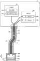
图1是表示本发明的一个实施方式所涉及的光学测量系统的概略结构的框图。图2是图1示出的光学测量系统的主要部分的截面图。为了便于说明,图2也示意性地示出了构成图1示出的光学测量系统的测量装置的主要部分。FIG. 1 is a block diagram showing a schematic configuration of an optical measurement system according to an embodiment of the present invention. FIG. 2 is a cross-sectional view of main parts of the optical measurement system shown in FIG. 1 . For convenience of description, FIG. 2 also schematically shows the main parts of the measuring device constituting the optical measuring system shown in FIG. 1 .
如图1所示,实施方式所涉及的光学测量系统1具备:测量装置2,其对生物体组织等测量对象进行光学测量来检测测量对象的性状;探头3,其被插入到被检体内;以及校正用构件4,其在测量装置2中的校正处理时被安装于探头3的前端33。探头3的基端可装卸自如地连接于测量装置2。探头3具有照射光纤和多个受光光纤。探头3将由基端提供的光从前端对测量对象射出,并且将从前端入射的来自测量对象的返回光即散射光、反射光从基端输出到测量装置2。As shown in FIG. 1 , an optical measurement system 1 according to an embodiment includes: a
测量装置2具备电源21、光源部22、连接部23、测量部24、输入部25、输出部26、控制部27以及存储部28。The
电源21对测量装置2的各结构要素提供电力。The
光源部22发出提供给探头3的光。光源部22具有白色光源22a和荧光激励用光源22b。使用白色LED、氙气灯或者卤素灯等低相干光源以及一个或者多个透镜来实现白色光源22a。白色光源22a按照规定定时对探头3提供低相干光。荧光激励用光源22b发出如下的光:该光的波长属于与测量部24中的散射光测量波长带不同的波长带,该光作为对后述的校正用构件4的荧光颗粒进行激励的激励光而发挥功能。The
连接部23将探头3的基端装卸自如地连接于测量装置2。连接部23将由光源部22发出的光提供给探头3,并且将从探头3输出的返回光输出到测量部24。The connecting
测量部24对从探头3输出的光即来自生物体组织的返回光进行测量。使用分光计来实现测量部24。测量部24对从探头3输出的返回光的光谱成分和强度等进行测量,并按每个波长进行测量。测量部24将测量结果输出到控制部27。测量部24以与由光源部22进行的发光处理对应的规定的测量定时来反复进行返回光的测量处理。测量部24对后述的探头3的多个受光光纤35、36(参照图2)分别设置测量部,在图1示出的例子中,具有第一测量部24a和第二测量部24b这两个分光计。The
利用推式开关等来实现输入部25,通过操作开关等来接收指示启动测量装置2的指示信息、其它各种指示信息并输入到控制部27。The
输出部26输出与光学测量装置1的各种处理有关的信息。利用显示器、扬声器或者马达等来实现输出部26,输出部26通过输出图像信息、声音信息或者振动来输出与光学测量系统1的各种处理有关的信息。The
控制部27对测量装置2的各结构要素的处理动作进行控制。使用CPU和RAM等半导体存储器来实现控制部27。控制部27通过针对测量装置2的各结构要素进行指示信息、数据的输送等,来控制测量装置2的动作。控制部27具有运算部27a、校正处理部27b以及照射光切换控制部27c。The
运算部27a根据测量部24的测量结果来进行多种运算处理,对与生物体组织的性状有关的特性值进行运算。例如按照由操作者的操作从输入部25输入的指示信息来设定由运算部27a进行运算的特性值、即作为获取对象的特性值的种类。The calculation unit 27a performs various calculation processing based on the measurement result of the
校正处理部27b控制光源部22和测量部24,在开始对测量对象进行检测之前,进行为了保证检测精度而针对测量装置2的校正处理。每次在更换探头3时进行校正处理The
照射光切换控制部27c在光源部22中的白色光源22a与荧光激励用光源22b之间进行切换实际发出光的光源的控制。照射光切换控制部27c在对测量对象进行散射光测量的情况下,对白色光源22a进行照射处理。照射光切换控制部27c在进行校正处理的情况下,与校正处理的内容对应地对白色光源22a和荧光激励用光源22b中的某一个进行照射处理。The irradiation light switching control unit 27 c controls to switch the light source that actually emits light between the
存储部28存储使测量装置2执行光学测量处理的光学测量程序,并且存储与光学测量处理有关的各种信息。存储部28存储由运算部27a运算得到的特性值。存储部28存储使测量装置2执行校正处理的校正用程序,并且存储与校正处理有关的各种信息。The
使用多个光纤来实现探头3。探头3具有:基端部31,其装卸自如地连接于测量装置2的连接部23;可挠部32,其具有可挠性;以及前端33,其射出由光源部22提供的光,并且入射来自测量对象的散射光。在使用LEBS技术的情况下,分别会聚散射角度不同的至少两个散射光,因此设置多个聚光光纤。具体地说,如图2所示,探头3具有:照射光纤34,其将从基端提供的来自光源部22的光从前端照射到测量对象;以及两个受光光纤35、36,其将从前端入射的来自测量对象的互不相同的散射角度的散射光、反射光从基端分别输出,探头3具有以下结构:照射光纤34的侧面与多个受光光纤35、36的侧面被覆盖部37覆盖。光学测量装置1例如与用于观察消化器官等脏器的内窥镜系统相配合使用,探头3经由插入到被检体内的内窥镜的探头用通道被导入到被检体内部。Probe 3 is realized using multiple optical fibers. The probe 3 has: a
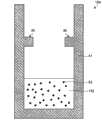
在光学测量系统1中,在探头3的前端33被校正用构件4覆盖的状态下,进行测量开始前的校正处理。图3是图1和图2示出的校正用构件4的截面图。In the optical measurement system 1 , the calibration process before the start of measurement is performed in a state where the
如图2和图3所示,校正用构件4具有以下结构,即在覆盖探头3的前端33的呈帽子形状的主体框架41的内部设置有固体的介质42。散射颗粒43和荧光颗粒44分散在介质42的内部。介质42例如为硅树脂、聚乙烯类树脂、明胶、丙烯酸树脂、聚酰胺等透明固体,由比散射颗粒43和荧光颗粒44足够大的颗粒形成。散射颗粒43为聚苯乙烯颗粒、氧化铝微颗粒等。As shown in FIGS. 2 and 3 , the calibration member 4 has a structure in which a
荧光颗粒44在被照射属于规定波长带的激励光的情况下,发出具有比该激励光长的波长的荧光。图4是说明图3示出的荧光颗粒44的荧光特性的图。测量部24以从波长λa至波长λb的散射光测量波长带W进行分光处理。荧光颗粒44当被属于与该测量部24的散射光测量波长带W不同的波长带的波长λc的光激励时,发出属于曲线Lb示出的波长带、即测量部24的散射光测量波长带W所包含的波长带的波长的荧光。因此,荧光激励用光源22b照射例如曲线La所示,以波长λc为峰的波长带的激励光。预先求出入射到校正用构件4的荧光颗粒44的激励光的强度与由荧光颗粒44发出的荧光强度之间的关系。
另外,荧光颗粒44在被照射属于激励波长带的波长以外的光的情况下,与散射颗粒43同样地作为散射体而起作用。散射颗粒43和荧光颗粒44具有规定的散射特性和反射特性,预先求得根据所入射的白色光来进行散射、反射的返回光的波长分布状态。关于介质42、散射颗粒43以及荧光颗粒44,根据入射光的波长和返回光的波长与颗粒之间的关系,来设定材料、颗粒尺寸。In addition, the
为了在固定条件下稳定地执行校正处理,校正用构件4的主体框架41在探头3的前端33和介质42的表面隔着固定距离D(参照图2)相对的位置,在内部具备使覆盖部37表面与校正用构件4进行接合的突起状的止挡件45。将距离D设定成来自照射光纤34的光在充分扩散的状态下入射到介质42。In order to stably execute the calibration process under fixed conditions, the
校正处理部27b根据由测量部24对从多个受光光纤35、36输出的输出光进行测量的测量结果,来对多个受光光纤35、36间的受光强度的关系进行校正,该输出光是针对由于激励光的照射而从荧光颗粒44产生荧光的输出光。并且,校正处理部27b根据由测量部24对对于白色光的照射而从散射颗粒43和荧光颗粒44产生的反射光、散射光进行测量的测量结果,来对测量部24的第一测量部24a和第二测量部24b的光谱灵敏度进行校正。The
接着,说明光学测量系统1中的校正处理。图5是表示图1示出的光学测量系统1中的校正处理的处理过程的流程图。此外,在图5中,举例说明在获取到校正用的测量结果之后继续进行校正处理的情况。Next, correction processing in the optical measurement system 1 will be described. FIG. 5 is a flowchart showing a processing procedure of correction processing in the optical measurement system 1 shown in FIG. 1 . In addition, in FIG. 5, the case where calibration processing is continued after acquisition of the measurement result for calibration is demonstrated by example.
如图5所示,首先,控制部27判断是否指示了开始校正处理(步骤S1)。例如在从输入部25输入了指示开始校正处理的指示信息的情况下、或检测出更换了探头3的情况下,控制部27判断为指示了开始校正处理。控制部27在判断为没有指示开始校正处理的情况下(步骤S1:“否”),返回到步骤S1,在指示开始校正处理之前反复进行步骤S1的判断处理。As shown in FIG. 5 , first, the
在控制部27判断为指示了开始校正处理的情况下(步骤S1:“是”),校正处理部27b进行用于校正多个受光光纤35、36间的受光强度的关系的校正处理。首先,在校正处理部27b的控制下,照射光切换控制部27c将使用光源切换为荧光激励用光源22b,将照射光切换为激励光(步骤S2)。接着,校正处理部27b使荧光激励用光源22b以规定强度照射以波长λc为峰值的激励光(步骤S3)。由荧光激励用光源22b所照射的激励光从探头3的照射光纤34的前端照射到校正用构件4的内部。其结果,校正用构件4的荧光颗粒44发出荧光。来自该荧光颗粒44的荧光不呈现相干且进行扩散放射。即,不受到干涉的影响,与激励光相应的固定强度的荧光分别入射到受光光纤35、36。When the
测量部24测量各受光光纤35、36的荧光的受光强度(步骤S4)。在图2示出的例子中,第一测量部24a测量受光光纤35的受光强度,第二测量部24b测量受光光纤36的受光强度。The measuring
接着,校正处理部27b根据由测量部24对各受光光纤35、36进行处理的受光强度测量结果,对受光光纤35、36之间的受光强度的关系进行校正(步骤S5)。在该情况下,固定强度的荧光分别入射到受光光纤35、36。因此,校正处理部27b与实际入射到各受光光纤35、36的荧光强度对应地,对在测量部24中测量的各受光光纤35、36的受光强度的比进行校正。这样,校正处理部27b基于由激励光产生的来自校正用构件4的荧光颗粒44的荧光,来对各受光光纤35、36间的受光强度的关系进行校正。Next, the
在步骤S5结束之后,校正处理部27b进行用于对测量部24的第一测量部24a和第二测量部24b的光谱灵敏度进行校正的校正处理。首先,在校正处理部27b的控制下,照射光切换控制部27c将使用光源切换为白色光源22a,将照射光切换为白色光(步骤S6)。接着,校正处理部27b使白色光源22a在规定条件下照射白色光(步骤S7)。从白色光源22a照射的白色光从探头3的照射光纤34的前端照射到校正用构件4的内部。其结果,光通过作为散射体而发挥功能的校正用构件4的散射颗粒43和荧光颗粒44来散射和反射,作为返回光,与入射的白色光相应的固定的散射光、反射光分别入射到受光光纤35、36。After step S5 ends, the
测量部24的第一测量部24a和第二测量部24b分别对各受光光纤35、36的返回光进行分光测量(步骤S8)。在该情况下,由在固定条件下照射的白色光而产生的具有固定的波长分布的返回光入射到受光光纤35、36。预先求得该返回光的波长分布。校正处理部27b将预先求得的该返回光的波长分布与实际由第一测量部24a和第二测量部24b得到的分光测量结果进行比较,对第一测量部24a和第二测量部24b的各测量器的光谱灵敏度进行校正(步骤S9)。这样,校正处理部27b基于由白色光产生的来自校正用构件4的返回光来对各测量器的光谱灵敏度进行校正。The
在步骤S9结束之后,控制部27将校正处理结束的意思通知给输出部26(步骤S10),结束校正处理。此外,也可以提前进行针对受光光纤35、36间的受光强度的校正处理以及针对第一测量部24a和第二测量部24b的光谱灵敏度的校正处理中的任一处理。因此,还能够替换步骤S2~步骤S5和步骤S6~步骤S9。After step S9 is completed, the
这样,在实施方式所涉及的光学测量系统1中,使用具有散射特性和荧光特性两者的校正用构件4。在光学测量系统1中,基于因照射激励光而从荧光体产生的荧光来对受光光纤35、36间的受光强度的关系进行校正,基于由白色光产生的来自散射体的返回光来对测量部24的光谱灵敏度进行校正,因此能够正确地执行对受光光纤35、36的校正以及对测量部24的校正两者。In this way, in the optical measurement system 1 according to the embodiment, the calibration member 4 having both scattering properties and fluorescence properties is used. In the optical measurement system 1, the relationship between the received light intensity between the light-receiving
另外,在光学测量系统1中,仅对光源部22设置荧光激励用光源22b,使用一个校正用构件4能够执行两种校正,即对受光光纤35、36的受光强度的关系的校正以及对测量部24的光谱灵敏度的校正。因此,在光学测量系统1中,并不需要为了进行校正处理而独立地准备扩散光源,因此能够以简单的结构执行校正处理。另外,在光学测量系统1中,并不需要按照校正处理的内容来更换校正构件,因此不进行烦杂的处理而能够简单地执行校正处理。In addition, in the optical measurement system 1, only the
另外,在光学测量系统1中,使用在固体介质42内分散散射颗粒43和荧光颗粒44的校正用构件4,因此即使探头3的前端33和校正用构件4朝向任何朝向也能够正确地执行校正处理。In addition, in the optical measurement system 1, the correction member 4 in which the
此外,在实施方式中,举例说明了作为校正用构件在主体框架41内部设置了止挡件45的情况,但当然并不限定于此,例如,也可以以探头3的前端33与介质42的表面隔着固定距离D(参照图2)而相对的方式,在覆盖部37的侧面前端部中设置突起部,在校正用构件4的主体框架41的内壁设置突起部通过的槽。设置于校正用构件4主体的内壁的槽从上部起至与距离D对应的内壁的途中部位为止向下延伸。In addition, in the embodiment, the case where the
另外,在实施方式中,说明了作为校正用构件如图3所示散射颗粒43和荧光颗粒44两者分散在介质42中的结构,但是荧光颗粒44作为散射体而发挥功能,因此也可以是仅使荧光颗粒44分散至介质42的结构。In addition, in the embodiment, the structure in which both the
另外,在实施方式中,说明了作为校正用构件而将散射颗粒43分散至介质42内的结构,但当然也不限定于此,如图6的校正用构件104所示,也可以使散射颗粒43分散至荧光体142内部,使荧光体142作为分散散射颗粒43的介质。在该情况下,荧光体142为能够使可见光透过的固体。即使在该情况下,在校正用构件104内部,以探头3的前端33与作为固体的荧光体142的表面隔着固定距离相对的方式,设置有止挡件45。In addition, in the embodiment, the structure in which the
另外,在实施方式中,说明了作为校正用构件而使散射颗粒43分散至作为固体的介质42或者荧光体142的内部的结构,但是介质42或者荧光体142不一定必须是固体。如图7所示,在水平面能够设置校正用构件204的情况下,也可以使用液体或者凝胶状的介质242。即使在该情况下,在校正用构件204的主体框架内部,在将校正用构件204设置于水平面的情况下也以探头3的前端与介质242的表面隔着固定距离D相对的方式,设置有止挡件245。In addition, in the embodiment, the structure in which the
另外,在本实施方式中,举例说明了除了白色光源22a以外设置荧光激励用光源22b的结构,但当然也不限定于此,除了设置白色光源22a以外,也可以设置仅允许由设置于校正用构件4、104、204的荧光体产生的激励波长光透过的可移动的过滤器。在该情况下,照射光切换控制部27c在对多个受光光纤间的受光强度的关系进行校正的情况下,使该过滤器位于来自白色光源22a的白色光的光路上即可。另外,照射光切换控制部27c在对测量部24的第一测量部24a和第二测量部24b的光谱灵敏度进行校正的情况下和在进行用于获取特性值的测量处理的情况下,使过滤器从来自白色光源22a的白色光的光路中退出即可。In addition, in this embodiment, the structure in which the fluorescent
另外,在本实施方式中,举例说明了在获取校正用的测量结果之后继续进行校正处理的情况,但是,如果获取到校正用的测量结果,则校正处理本身也能够在用于获取特性值的测量之后进行。In addition, in this embodiment, the case where the calibration processing is continued after obtaining the measurement results for calibration has been described as an example. However, if the measurement results for calibration are obtained, the calibration processing itself can also be performed in the process for obtaining the characteristic value. after measurement.
附图标记说明Explanation of reference signs
1:光学测量系统;2:测量装置;3:探头;4、104、204:校正用构件;21:电源;22:光源部;22a:白色光源;22b:荧光激励用光源;23:连接部;24:测量部;25:输入部;26:输出部;27:控制部;27a:运算部;27b:校正处理部;27c:照射光切换控制部;28:存储部;31:基端部;32:可挠部;33:前端;34:照射光纤;35、36:受光光纤;37:覆盖部;41:主体框架;42、242:介质;43:散射颗粒;44:荧光颗粒;45:止挡件;142:荧光体。1: Optical measurement system; 2: Measuring device; 3: Probe; 4, 104, 204: Calibration components; 21: Power supply; 22: Light source part; 22a: White light source; 22b: Light source for fluorescence excitation; 23: Connection part ;24: measurement unit; 25: input unit; 26: output unit; 27: control unit; 27a: calculation unit; 27b: correction processing unit; 27c: irradiation light switching control unit; ;32: Flexible part; 33: Front end; 34: Irradiating fiber; 35, 36: Light receiving fiber; 37: Covering part; 41: Main frame; 42, 242: Medium; 43: Scattering particles; 44: Fluorescent particles; 45 : stopper; 142 : phosphor.
Claims (19)
Applications Claiming Priority (3)
| Application Number | Priority Date | Filing Date | Title |
|---|---|---|---|
| US201161477884P | 2011-04-21 | 2011-04-21 | |
| US61/477,884 | 2011-04-21 | ||
| PCT/JP2012/060467WO2012144522A1 (en) | 2011-04-21 | 2012-04-18 | Optical measuring system, optical measuring apparatus, calibration member, and calibration method |
Publications (2)
| Publication Number | Publication Date |
|---|---|
| CN103328953Atrue CN103328953A (en) | 2013-09-25 |
| CN103328953B CN103328953B (en) | 2015-07-01 |
Family
ID=47041628
Family Applications (1)
| Application Number | Title | Priority Date | Filing Date |
|---|---|---|---|
| CN201280005526.8AExpired - Fee RelatedCN103328953B (en) | 2011-04-21 | 2012-04-18 | Optical measurement system, optical measurement device, calibration member, and calibration method |
Country Status (5)
| Country | Link |
|---|---|
| US (1) | US8558164B2 (en) |
| EP (1) | EP2653854B1 (en) |
| JP (1) | JP5276228B2 (en) |
| CN (1) | CN103328953B (en) |
| WO (1) | WO2012144522A1 (en) |
Cited By (6)
| Publication number | Priority date | Publication date | Assignee | Title |
|---|---|---|---|---|
| CN105277490A (en)* | 2014-06-20 | 2016-01-27 | 大塚电子株式会社 | Dynamic light scattering measurement device and dynamic light scattering measurement method |
| CN105683739A (en)* | 2013-11-01 | 2016-06-15 | 恩特葛瑞斯-捷特隆解决方案公司 | Dissolved oxygen sensor |
| CN108368473A (en)* | 2015-12-25 | 2018-08-03 | 理音株式会社 | Correction method and correction device for biological particle counter |
| US10107755B2 (en) | 2014-03-20 | 2018-10-23 | Entegris, Inc. | System and method for dectection and signaling of component end-of-life in a dissolved oxygen sensor |
| CN109724700A (en)* | 2017-10-27 | 2019-05-07 | 精工爱普生株式会社 | Spectroscopic measuring device, spectroscopic measuring method |
| CN113841043A (en)* | 2019-05-22 | 2021-12-24 | 株式会社堀场先进技术 | Water quality analysis system, sensor module, calibration equipment, and calibration method of water quality analysis system |
Families Citing this family (6)
| Publication number | Priority date | Publication date | Assignee | Title |
|---|---|---|---|---|
| DE102013207166A1 (en)* | 2013-04-19 | 2014-10-23 | Robert Bosch Gmbh | Test device for a scattered light measuring device, method for manufacturing a test device for a scattered light measuring device and method for checking a scattered light measuring device |
| FR3034869A1 (en) | 2015-04-09 | 2016-10-14 | Nodea Medical | DEVICE, KIT AND METHOD FOR CALIBRATING FLUORESCENCE |
| EP3309451A4 (en) | 2015-06-10 | 2019-02-20 | Olympus Corporation | LIGHTING DEVICE |
| WO2018183051A1 (en)* | 2017-03-27 | 2018-10-04 | Ecolab Usa Inc. | Techniques and materials for calibrating optical sensors |
| DE102023133021A1 (en)* | 2022-12-09 | 2024-06-20 | Endress+Hauser Conducta Gmbh+Co. Kg | Calibration standard, sensor arrangement and use |
| FR3159837A1 (en)* | 2024-03-04 | 2025-09-05 | Commissariat A L' Energie Atomique Et Aux Energies Alternatives | Method for characterizing an optical probe |
Citations (4)
| Publication number | Priority date | Publication date | Assignee | Title |
|---|---|---|---|---|
| WO2001034031A1 (en)* | 1999-11-05 | 2001-05-17 | Spectrx, Inc. | Multi-modal optical tissue diagnostic system |
| US20020133080A1 (en)* | 2001-02-06 | 2002-09-19 | William Apruzzese | Layered calibration standard for tissue sampling |
| CN1882828A (en)* | 2003-11-14 | 2006-12-20 | 浜松光子学株式会社 | Fluorescence measuring device |
| JP2009537014A (en)* | 2006-05-12 | 2009-10-22 | ノースウェスタン ユニバーシティ | Low coherence enhanced backscatter spectroscopy system, method and apparatus |
Family Cites Families (9)
| Publication number | Priority date | Publication date | Assignee | Title |
|---|---|---|---|---|
| JP2002303547A (en)* | 2001-04-03 | 2002-10-18 | Canon Inc | Integrating sphere, spectrometer and spectrometer using the same |
| JP2003004365A (en) | 2001-06-22 | 2003-01-08 | Hitachi Ltd | Liquid crystal display device of refrigerator, refrigerator and display selection method of liquid crystal display device |
| JP2003004635A (en)* | 2001-06-25 | 2003-01-08 | Mutsuro Okino | Fluorescence type oxygen analyzer |
| JP4716673B2 (en)* | 2004-05-21 | 2011-07-06 | オリンパス株式会社 | Fluorescence endoscope device |
| US8131348B2 (en) | 2006-05-12 | 2012-03-06 | Northshore University Healthsystem | Systems, methods and apparatuses of elastic light scattering spectroscopy and low coherence enhanced backscattering spectroscopy |
| US20100317919A1 (en) | 2006-10-23 | 2010-12-16 | Olympus Corporation | Spectral endoscope and its wavelength calibration method |
| US7840102B2 (en) | 2007-01-16 | 2010-11-23 | Baker Hughes Incorporated | Distributed optical pressure and temperature sensors |
| JP2009236709A (en)* | 2008-03-27 | 2009-10-15 | Fujifilm Corp | Surface plasmon sensing method and surface plasmon sensing device |
| CN101621915B (en) | 2008-07-04 | 2011-07-27 | 鸿富锦精密工业(深圳)有限公司 | Heat dissipating device and bracket thereof |
- 2012
- 2012-04-18JPJP2012547408Apatent/JP5276228B2/ennot_activeExpired - Fee Related
- 2012-04-18EPEP12773711.2Apatent/EP2653854B1/ennot_activeNot-in-force
- 2012-04-18CNCN201280005526.8Apatent/CN103328953B/ennot_activeExpired - Fee Related
- 2012-04-18WOPCT/JP2012/060467patent/WO2012144522A1/enactiveApplication Filing
- 2012-10-15USUS13/651,711patent/US8558164B2/ennot_activeExpired - Fee Related
Patent Citations (4)
| Publication number | Priority date | Publication date | Assignee | Title |
|---|---|---|---|---|
| WO2001034031A1 (en)* | 1999-11-05 | 2001-05-17 | Spectrx, Inc. | Multi-modal optical tissue diagnostic system |
| US20020133080A1 (en)* | 2001-02-06 | 2002-09-19 | William Apruzzese | Layered calibration standard for tissue sampling |
| CN1882828A (en)* | 2003-11-14 | 2006-12-20 | 浜松光子学株式会社 | Fluorescence measuring device |
| JP2009537014A (en)* | 2006-05-12 | 2009-10-22 | ノースウェスタン ユニバーシティ | Low coherence enhanced backscatter spectroscopy system, method and apparatus |
Cited By (9)
| Publication number | Priority date | Publication date | Assignee | Title |
|---|---|---|---|---|
| CN105683739A (en)* | 2013-11-01 | 2016-06-15 | 恩特葛瑞斯-捷特隆解决方案公司 | Dissolved oxygen sensor |
| US10107755B2 (en) | 2014-03-20 | 2018-10-23 | Entegris, Inc. | System and method for dectection and signaling of component end-of-life in a dissolved oxygen sensor |
| CN105277490A (en)* | 2014-06-20 | 2016-01-27 | 大塚电子株式会社 | Dynamic light scattering measurement device and dynamic light scattering measurement method |
| CN108368473A (en)* | 2015-12-25 | 2018-08-03 | 理音株式会社 | Correction method and correction device for biological particle counter |
| CN108368473B (en)* | 2015-12-25 | 2022-03-01 | 理音株式会社 | Calibration method of biological particle counter and calibration device of biological particle counter |
| CN109724700A (en)* | 2017-10-27 | 2019-05-07 | 精工爱普生株式会社 | Spectroscopic measuring device, spectroscopic measuring method |
| CN113841043A (en)* | 2019-05-22 | 2021-12-24 | 株式会社堀场先进技术 | Water quality analysis system, sensor module, calibration equipment, and calibration method of water quality analysis system |
| CN113841043B (en)* | 2019-05-22 | 2024-12-20 | 株式会社堀场先进技术 | Water quality analysis system, sensor module, calibration device, and calibration method for water quality analysis system |
| US12436105B2 (en) | 2019-05-22 | 2025-10-07 | Horiba Advanced Techno, Co., Ltd. | Water quality analysis system, sensor module, calibration machine, and method for calibrating water quality analysis system |
Also Published As
| Publication number | Publication date |
|---|---|
| JP5276228B2 (en) | 2013-08-28 |
| EP2653854A4 (en) | 2013-11-13 |
| US20130206971A1 (en) | 2013-08-15 |
| EP2653854B1 (en) | 2014-12-31 |
| CN103328953B (en) | 2015-07-01 |
| WO2012144522A1 (en) | 2012-10-26 |
| EP2653854A1 (en) | 2013-10-23 |
| US8558164B2 (en) | 2013-10-15 |
| JPWO2012144522A1 (en) | 2014-07-28 |
Similar Documents
| Publication | Publication Date | Title |
|---|---|---|
| CN103328953B (en) | Optical measurement system, optical measurement device, calibration member, and calibration method | |
| JP6321668B2 (en) | Efficient modulation imaging | |
| US8214025B2 (en) | Fluorescence endoscope system | |
| JP6205346B2 (en) | Optical measuring apparatus and fiber bundle association method | |
| EP2526851A1 (en) | Probe and optical measurement device | |
| EP2896347B1 (en) | Scattered light measurement device | |
| JP2014098653A (en) | Spectrometry device | |
| CN110621981A (en) | Non-invasive optical sensor for analyzing substance level in subject by irradiating sclera | |
| ATE361699T1 (en) | ANALYSIS OF A COMPILATION WITH OBSERVATION | |
| CN103200858B (en) | Optical measuring device | |
| CN104937397B (en) | Calibration method and device, and body fluid composition measurement device calibrated using the method | |
| KR101887033B1 (en) | Multimodal imaging system for dental structure/function imaging | |
| CN103153160B (en) | Optical detecting device | |
| JP5420163B2 (en) | Biological measuring device | |
| KR20190075795A (en) | Endoscope system for multi image | |
| RU131184U1 (en) | SYSTEM FOR OPTICAL DIAGNOSTICS OF TUMOR TISSUE | |
| KR101033516B1 (en) | Photometric Application Oral Cancer Early Diagnosis System and Method | |
| EP2823750A1 (en) | Optical measuring device | |
| WO2025076514A1 (en) | Handheld imaging system for identify and locating tissue | |
| JP5060268B2 (en) | Biological measuring device and calibration jig | |
| CN103841875A (en) | Bio-optical measurement device and measurement probe |
Legal Events
| Date | Code | Title | Description |
|---|---|---|---|
| C06 | Publication | ||
| PB01 | Publication | ||
| C10 | Entry into substantive examination | ||
| SE01 | Entry into force of request for substantive examination | ||
| C14 | Grant of patent or utility model | ||
| GR01 | Patent grant | ||
| C41 | Transfer of patent application or patent right or utility model | ||
| TR01 | Transfer of patent right | Effective date of registration:20151111 Address after:Tokyo, Japan, Japan Patentee after:Olympus Corporation Address before:Tokyo, Japan, Japan Patentee before:Olympus Medical Systems Corp. | |
| CF01 | Termination of patent right due to non-payment of annual fee | Granted publication date:20150701 Termination date:20170418 | |
| CF01 | Termination of patent right due to non-payment of annual fee |