CN103328161A - Multi-joint arm robot, control method, and control program - Google Patents
Multi-joint arm robot, control method, and control programDownload PDFInfo
- Publication number
- CN103328161A CN103328161ACN2011800046315ACN201180004631ACN103328161ACN 103328161 ACN103328161 ACN 103328161ACN 2011800046315 ACN2011800046315 ACN 2011800046315ACN 201180004631 ACN201180004631 ACN 201180004631ACN 103328161 ACN103328161 ACN 103328161A
- Authority
- CN
- China
- Prior art keywords
- arm
- joint
- joint portion
- mode
- rotation
- Prior art date
- Legal status (The legal status is an assumption and is not a legal conclusion. Google has not performed a legal analysis and makes no representation as to the accuracy of the status listed.)
- Granted
Links
Images


Classifications
- B—PERFORMING OPERATIONS; TRANSPORTING
- B25—HAND TOOLS; PORTABLE POWER-DRIVEN TOOLS; MANIPULATORS
- B25J—MANIPULATORS; CHAMBERS PROVIDED WITH MANIPULATION DEVICES
- B25J9/00—Programme-controlled manipulators
- B25J9/06—Programme-controlled manipulators characterised by multi-articulated arms
- B—PERFORMING OPERATIONS; TRANSPORTING
- B25—HAND TOOLS; PORTABLE POWER-DRIVEN TOOLS; MANIPULATORS
- B25J—MANIPULATORS; CHAMBERS PROVIDED WITH MANIPULATION DEVICES
- B25J3/00—Manipulators of leader-follower type, i.e. both controlling unit and controlled unit perform corresponding spatial movements
- B—PERFORMING OPERATIONS; TRANSPORTING
- B25—HAND TOOLS; PORTABLE POWER-DRIVEN TOOLS; MANIPULATORS
- B25J—MANIPULATORS; CHAMBERS PROVIDED WITH MANIPULATION DEVICES
- B25J9/00—Programme-controlled manipulators
- B25J9/02—Programme-controlled manipulators characterised by movement of the arms, e.g. cartesian coordinate type
- B25J9/04—Programme-controlled manipulators characterised by movement of the arms, e.g. cartesian coordinate type by rotating at least one arm, excluding the head movement itself, e.g. cylindrical coordinate type or polar coordinate type
- B25J9/041—Cylindrical coordinate type
- B25J9/042—Cylindrical coordinate type comprising an articulated arm
- B—PERFORMING OPERATIONS; TRANSPORTING
- B25—HAND TOOLS; PORTABLE POWER-DRIVEN TOOLS; MANIPULATORS
- B25J—MANIPULATORS; CHAMBERS PROVIDED WITH MANIPULATION DEVICES
- B25J9/00—Programme-controlled manipulators
- B25J9/02—Programme-controlled manipulators characterised by movement of the arms, e.g. cartesian coordinate type
- B25J9/04—Programme-controlled manipulators characterised by movement of the arms, e.g. cartesian coordinate type by rotating at least one arm, excluding the head movement itself, e.g. cylindrical coordinate type or polar coordinate type
- B25J9/046—Revolute coordinate type
- B25J9/047—Revolute coordinate type the pivoting axis of the first arm being offset to the vertical axis
Landscapes
- Engineering & Computer Science (AREA)
- Robotics (AREA)
- Mechanical Engineering (AREA)
- Manipulator (AREA)
Abstract
Description
Translated fromChinese技术领域technical field
本发明涉及具有多个关节部的多关节型臂机器人、控制方法以及控制程序。The present invention relates to an articulated arm robot having a plurality of joints, a control method, and a control program.
背景技术Background technique
一般来说,对与人共处进行作业的臂机器人要求高的安全性,为了安全地操作臂机器人,优选充分地降低其驱动力来确保安全性。但是,在类似于人的胳膊的臂轴构成中,当想要通过一般的垂直多关节臂来兼顾大的可动区域和应对大的工件重量时,尤其是力矩长度变长的臂基部的关节需要大的驱动力。因此,不能说是安全且低消耗电力的臂构成。In general, high safety is required for arm robots that work together with humans, and in order to operate the arm robots safely, it is preferable to sufficiently reduce the driving force to ensure safety. However, in the configuration of the arm shaft similar to the human arm, when a general vertical multi-joint arm is intended to balance a large movable area and a large workpiece weight, especially the joint at the base of the arm with a longer moment length A large driving force is required. Therefore, it cannot be said that it is a safe arm configuration with low power consumption.
另一方面,使用组合了水平多关节轴和铅垂轴的SCARA(SCARA:Selective Compliance Assembly Robot Arm,选择顺应性装配机器手臂)机器人等产业用机器人,来进行组装作业等。另外,已知有如下的多关节机器人:构成偏移旋转关节,所述偏移旋转关节在主动侧连杆和从动侧连杆之间在相对于连杆轴线倾斜的面上设置旋转控制构造,并且从动侧连杆具有相对于连杆轴线倾斜的偏移旋转轴线,在机器人主体与末端操纵器之间设置有多级该偏移旋转关节(例如参照专利文献1)。On the other hand, industrial robots such as SCARA (SCARA: Selective Compliance Assembly Robot Arm) robots that combine a horizontal multi-joint axis and a vertical axis are used for assembly work. In addition, there is known a multi-joint robot in which an offset rotary joint is provided with a rotation control structure on a surface inclined with respect to the link axis between the driving side link and the driven side link. , and the driven side link has an offset rotation axis inclined with respect to the link axis, and multiple stages of the offset rotation joint are provided between the robot body and the end effector (for example, refer to Patent Document 1).
在先技术文献prior art literature
专利文献patent documents
专利文献1:日本专利文献特开平10-225881号公报。Patent Document 1: Japanese Patent Laid-Open No. H10-225881.
发明内容Contents of the invention
发明所要解决的问题The problem to be solved by the invention
但是,在上述SCARA机器人中,由于工件和臂自身的重量未作用于转动轴,因此具有能够将其驱动力抑制得较低的优点,但是,另一方面具有臂的上下方向的可动区域被限定而变狭小的缺点。However, in the above-mentioned SCARA robot, since the weight of the workpiece and the arm itself does not act on the rotation axis, there is an advantage that the driving force can be suppressed low, but on the other hand, the movable area of the arm in the vertical direction is restricted. The disadvantage of narrowing and narrowing.
另外,在上述专利文献1所示的多关节机器人中,虽然能够扩大可动范围,但是构成有可能复杂化。In addition, in the articulated robot disclosed in
本发明是为了解决上述的问题而完成的,其主要目的在于提供能够通过简单的构成以低驱动力驱动臂并且能够在大范围移动的多关节型臂机器人、控制方法以及控制程序。The present invention was made to solve the above problems, and its main object is to provide an articulated arm robot, a control method, and a control program capable of driving an arm with a low driving force and moving over a wide range with a simple configuration.
用于解决问题的手段means of solving problems
用于达到上述目的的本发明的一个方式提供一种多关节型臂机器人,其特征在于,包括:支承部,所述支承部能够在上下方向上伸缩;第一臂部,所述第一臂部的一端经由第一关节部以能够绕横摆轴旋转的方式与所述支承部连结,在所述第一臂部的两端间设置有能够绕侧倾轴旋转的第二关节部;第二臂部,所述第二臂部的一端经由第三关节部以能够绕横摆轴或俯仰轴旋转的方式与所述第一臂部的另一端连结;末端操纵部,所述末端操纵部经由第四关节部以能够绕横摆轴或俯仰轴旋转的方式与所述第二臂部的另一端连结;驱动部,所述驱动部分别使所述第一至第四关节部旋转,并且使所述支承部伸缩;以及控制部,所述控制部将臂在使所述第一臂部、所述第二臂部、以及第三臂部仅在水平面内旋转的SCARA模式和使所述第二臂部和所述第三臂部仅在铅垂面内旋转的垂直模式之间切换,来进行所述第一至第四关节部的驱动部的驱动控制。根据该一个方式,能够通过简单的构成以低驱动力驱动臂并且使臂在大范围内移动。One aspect of the present invention to achieve the above object provides a articulated arm robot, characterized by including: a support portion capable of extending and contracting in the vertical direction; a first arm portion, the first arm One end of the arm part is connected to the support part through a first joint part so as to be rotatable around the yaw axis, and a second joint part rotatable around the roll axis is provided between both ends of the first arm part; Two arm parts, one end of the second arm part is connected to the other end of the first arm part in a manner capable of rotating around a yaw axis or a pitch axis via a third joint part; an end manipulator part, the end manipulator part The other end of the second arm is connected to the other end of the second arm in a rotatable manner around a yaw axis or a pitch axis via a fourth joint; a driving part that rotates the first to fourth joints respectively, and expanding and contracting the supporting part; and a control part that makes the arm rotate in a SCARA mode in which the first arm part, the second arm part, and the third arm part only in a horizontal plane and makes the The second arm unit and the third arm unit are switched between vertical modes in which they rotate only in a vertical plane, and drive control of the drive units of the first to fourth joint units is performed. According to this one aspect, it is possible to drive the arm with a low driving force and move the arm over a wide range with a simple configuration.
在上述一个方式中,也可以采用以下方式:所述控制部通过控制所述驱动部来使所述第二关节部绕侧倾轴旋转,由此进行将臂在所述第一、第三以及第四关节部的旋转轴成为铅垂方向的所述SCARA模式和所述第三及第四关节部的旋转轴成为水平方向的所述垂直模式之间切换的控制。由此,能够在SCARA模式下以低驱动力驱动臂,能够在垂直模式下使臂在大范围内移动。In the above-mentioned one form, the following form may be adopted: the control unit controls the driving unit to rotate the second joint unit around the roll axis, thereby performing the movement of the arm in the first, third, and Control for switching between the SCARA mode in which the rotation axis of the fourth joint is in the vertical direction and the vertical mode in which the rotation axes of the third and fourth joints are in the horizontal direction. Accordingly, the arm can be driven with a low driving force in the SCARA mode, and the arm can be moved over a wide range in the vertical mode.
在上述一个方式中,也可以采用以下方式:所述控制部在所述SCARA模式下控制所述驱动部来控制所述第一、第三以及第四关节部的旋转,以使施加给所述第二关节部的侧倾轴的转矩最小。由此,能够采用低驱动力的第二驱动部,能够提高臂的安全性以及实现低消耗电力化。In the above-mentioned one mode, the following mode may also be adopted: the control part controls the driving part in the SCARA mode to control the rotation of the first, third and fourth joint parts so that the The moment of the roll axis of the second joint portion is the smallest. Thereby, the second driving unit with low driving force can be employed, and the safety of the arm can be improved and power consumption can be reduced.
在上述一个方式中,也可以采用以下方式:所述控制部通过控制所述驱动部来控制所述第一、第三以及第四关节部的旋转,以使基于从所述第二关节部到末端操纵部的重心位置的、作用于所述第二关节部的力矩力最小。In the above-mentioned one mode, the following mode may also be adopted: the control part controls the rotation of the first, third and fourth joint parts by controlling the driving part, so that The moment force acting on the second joint part is the smallest at the position of the center of gravity of the end effector.
在上述一个方式中,也可以采用以下方式:所述重心位置包括工件重量。In one of the above-mentioned forms, the following form may also be adopted: the position of the center of gravity includes the weight of the workpiece.
在上述一个方式中,也可以采用以下方式:所述控制部在所述垂直模式下控制所述驱动部来控制所述第三及第四关节部的旋转,以使施加给所述第三关节部的俯仰轴的转矩最小。由此,能够采用低驱动力的第三驱动部,能够提高臂的安全性以及实现低消耗电力化。In the above-mentioned one form, the following form may also be adopted: the control part controls the drive part in the vertical mode to control the rotation of the third and fourth joint parts so that the force applied to the third joint The torque of the pitch axis of the part is the smallest. Thereby, the third driving unit with low driving force can be employed, and the safety of the arm can be improved and power consumption can be reduced.
在上述一个方式中,也可以采用以下方式:所述控制部通过控制所述驱动部来控制所述第三及第四关节部的旋转,使得以所述第三关节部的俯仰轴为中心的、基于从所述第三关节部到末端操纵部的重心位置的力矩为最小。In the above-mentioned one form, the following form may also be adopted: the control unit controls the rotation of the third and fourth joint units by controlling the drive unit, so that the pitch axis of the third joint unit is , the moment based on the position of the center of gravity from the third joint part to the terminal manipulator part is minimum.
在上述一个方式中,也可以采用以下方式:所述重心位置包括工件重量。In one of the above-mentioned forms, the following form may also be adopted: the position of the center of gravity includes the weight of the workpiece.
在上述一个方式中,也可以采用以下方式:在所述第三关节部为比所述第五关节部高的低处姿势的情况下,所述控制部控制所述第三及第四关节部的旋转,以使所述第四关节部相对于所述第三关节部和所述第五关节部的连线位于下侧,在所述第三关节部为比所述第五关节部低的高处姿势的情况下,所述控制部控制所述第三及第四关节部的旋转,以使所述第四关节部相对于所述第三关节部和所述第五关节部的连线位于上侧。In the above one aspect, the control unit may control the third and fourth joint sections when the third joint section is in a lower posture than the fifth joint section. rotation so that the fourth joint is located on the lower side with respect to the line connecting the third joint and the fifth joint, and the third joint is lower than the fifth joint In the case of a high posture, the control unit controls the rotation of the third and fourth joints such that the fourth joint is relatively straight with respect to a line connecting the third joint and the fifth joint located on the upper side.
在上述一个方式中,也可以采用以下方式:还包括第三臂部,所述第三臂部的一端经由第四关节部以能够绕横摆轴或俯仰轴旋转的方式与所述第二臂部的另一端连结,所述末端操纵部经由第五关节部以能够绕侧倾轴、俯仰轴以及横摆轴旋转的方式与所述第三臂部的另一端连结。In one of the above-mentioned forms, the following form may also be adopted: a third arm part is further included, and one end of the third arm part is rotatably connected to the second arm via a fourth joint part. The other end of the arm is connected to the other end of the third arm, and the end effector is connected to the other end of the third arm through a fifth joint so as to be rotatable about a roll axis, a pitch axis, and a yaw axis.
在上述一个方式中,也可以采用以下方式:所述控制部通过将臂切换为所述垂直模式来控制所述第三及第四关节部的旋转,由此收存所述第二臂部、第三臂部以及末端操纵部。由此,能够紧凑收存臂。In one of the above-mentioned forms, the following form may be adopted: the control part controls the rotation of the third and fourth joint parts by switching the arm to the vertical mode, thereby storing the second arm part, Third arm and end manipulator. Thereby, the arm can be compactly stored.
在上述一个方式中,也可以采用以下方式:在所述第二关节部上设置有不可逆的动力传递机构,所述动力传递机构将来自所述驱动部侧的输出转矩向所述第二关节部的侧倾轴侧传递,并且不将来自所述第二关节部的侧倾轴侧的转矩向所述驱动部侧传递。由此,能够采用低驱动力的第二驱动部,能够实现安全且低消耗电力的臂构成。In the above-mentioned one mode, the following mode may also be adopted: an irreversible power transmission mechanism is provided on the second joint part, and the power transmission mechanism transfers the output torque from the driving part side to the second joint part. The roll axis side of the joint portion is transmitted, and the torque from the roll axis side of the second joint portion is not transmitted to the driving portion side. Thereby, the second driving unit with low driving force can be employed, and a safe and low-power-consumption arm configuration can be realized.
在上述一个方式中,也可以采用以下方式:在所述支承部上设置有重力补偿机构,所述重力补偿机构支承从所述第一关节部到所述末端操纵部的重力。由此,能够采用低驱动力的第六驱动部,能够提高臂的安全性以及实现低消耗电力化。In the above-mentioned one form, the following form may also be adopted: a gravity compensating mechanism is provided on the support part, and the gravity compensating mechanism supports the gravity from the first joint part to the end manipulation part. Thereby, the sixth driving unit with low driving force can be employed, and the safety of the arm can be improved and power consumption can be reduced.
在上述一个方式中,也可以采用以下方式:还包括与所述支承部连结并可移动的移动体。由此,能够使臂在更大范围内移动。In one of the above-mentioned aspects, an aspect may be adopted in which a movable body connected to the support portion and movable is further included. Thereby, the arm can be moved in a wider range.
另一方面,用于达到上述目的的本发明的一个方式提供一种多关节型臂机器人的控制方法,所述多关节型臂机器人包括:支承部,所述支承部能够在上下方向上伸缩;第一臂部,所述第一臂部的一端经由第一关节部以能够绕横摆轴旋转的方式与所述支承部连结,在所述第一臂部的两端间设置有能够绕侧倾轴旋转的第二关节部;第二臂部,所述第二臂部的一端经由第三关节部以能够绕横摆轴或俯仰轴旋转的方式与所述第一臂部的另一端连结;末端操纵部,所述末端操纵部经由第四关节部以能够绕横摆轴或俯仰轴旋转的方式与所述第二臂部的另一端连结;以及驱动部,所述驱动部分别使所述第一至第四关节部旋转,并且使所述支承部伸缩,所述多关节型臂机器人的控制方法的特征在于,将臂在使所述第一臂部、所述第二臂部、以及第三臂部仅在水平面内旋转的SCARA模式和使所述第二臂部和所述第三臂部仅在铅垂面内旋转的垂直模式之间切换,来进行所述第一至第四关节部的驱动部的驱动控制。On the other hand, one aspect of the present invention for achieving the above object provides a method of controlling an articulated arm robot, the articulated arm robot including: a support part that can expand and contract in an up and down direction; A first arm part, one end of the first arm part is connected to the support part so as to be rotatable around the yaw axis via a first joint part, and a side arm is provided between the two ends of the first arm part to be able to turn around. a second joint unit that rotates around a tilt axis; and a second arm unit, one end of which is connected to the other end of the first arm unit so as to be rotatable about a yaw axis or a pitch axis via a third joint unit an end manipulator connected to the other end of the second arm rotatably around a yaw axis or a pitch axis via a fourth joint; The first to fourth joint parts are rotated, and the support part is expanded and contracted. The control method of the multi-joint arm robot is characterized in that the arm is moved between the first arm part, the second arm part, and switching between the SCARA mode in which the third arm rotates only in the horizontal plane and the vertical mode in which the second arm and the third arm rotate only in the vertical plane, to perform the first to third Drive control of the drive unit of the four-joint unit.
另外,用于达到上述目的的本发明的一个方式提供一种多关节型臂机器人的控制程序,所述多关节型臂机器人包括:支承部,所述支承部能够在上下方向上伸缩;第一臂部,所述第一臂部的一端经由第一关节部以能够绕横摆轴旋转的方式与所述支承部连结,在所述第一臂部的两端间设置有能够绕侧倾轴旋转的第二关节部;第二臂部,所述第二臂部的一端经由第三关节部以能够绕横摆轴或俯仰轴旋转的方式与所述第一臂部的另一端连结;末端操纵部,所述末端操纵部经由第四关节部以能够绕横摆轴或俯仰轴旋转的方式与所述第二臂部的另一端连结;以及驱动部,所述驱动部分别使所述第一至第四关节部旋转,并且使所述支承部伸缩,所述控制程序的特征在于,所述控制程序使计算机执行如下的处理:将臂在使所述第一臂部、所述第二臂部、以及第三臂部仅在水平面内旋转的SCARA模式和使所述第二臂部和所述第三臂部仅在铅垂面内旋转的垂直模式之间切换,来进行所述第一至第四关节部的驱动部的驱动控制。In addition, one aspect of the present invention for achieving the above object provides a control program for an articulated arm robot including: a support part that can expand and contract in the vertical direction; a first an arm part, one end of the first arm part is connected to the support part through a first joint part so as to be rotatable around the yaw axis, and a joint rotatable around the roll axis is provided between the two ends of the first arm part. a rotating second joint part; a second arm part, one end of the second arm part is connected to the other end of the first arm part so as to be rotatable about a yaw axis or a pitch axis via a third joint part; a control unit, the terminal control unit is connected to the other end of the second arm unit so as to be rotatable about a yaw axis or a pitch axis via a fourth joint unit; The first to fourth joint parts are rotated and the support parts are expanded and contracted, and the control program is characterized in that the control program causes the computer to execute the following process: the arm is moved between the first arm part and the second arm part. The second arm and the third arm are switched between a SCARA mode in which the arm and the third arm rotate only in the horizontal plane and a vertical mode in which the second arm and the third arm rotate only in the vertical plane. Driving control of the driving parts of the first to fourth joint parts.
发明效果Invention effect
根据本发明,能够通过简单的构成提供能够以低驱动力驱动臂并且使臂在大范围内移动的多关节型臂机器人、控制方法以及控制程序。According to the present invention, it is possible to provide an articulated arm robot, a control method, and a control program capable of driving the arm with a low driving force and moving the arm over a wide range with a simple configuration.
附图说明Description of drawings
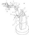
图1是表示本发明的实施方式1涉及的多关节型臂机器人的简要的构成的立体图;1 is a perspective view showing a schematic configuration of an articulated arm robot according to
图2是表示本发明的实施方式1涉及的多关节型臂机器人的简要的臂构成的框图;2 is a block diagram showing a schematic arm configuration of an articulated arm robot according to
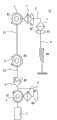
图3是表示本发明的实施方式1涉及的多关节型臂机器人的简要的系统构成的框图;3 is a block diagram showing a schematic system configuration of an articulated arm robot according to
图4是表示SCARA模式下的多关节型臂机器人的状态的一个例子的侧面图;4 is a side view showing an example of the state of the articulated arm robot in SCARA mode;
图5是表示SCARA模式下的多关节型臂机器人的状态的一个例子的立体图;5 is a perspective view showing an example of the state of the articulated arm robot in SCARA mode;
图6是表示垂直模式下的多关节型臂机器人的状态的一个例子的侧面图;6 is a side view showing an example of the state of the articulated arm robot in the vertical mode;
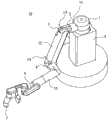
图7是表示垂直模式下的多关节型臂机器人的状态的一个例子的立体图;7 is a perspective view showing an example of the state of the articulated arm robot in the vertical mode;
图8是表示SCARA模式下的臂的可动范围的一个例子的图;FIG. 8 is a diagram showing an example of the movable range of the arm in the SCARA mode;
图9是表示垂直模式的低处的臂的可动范围的一个例子的图;9 is a diagram showing an example of the movable range of the lower arm in the vertical mode;
图10是表示垂直模式的高处的臂的可动范围的一个例子的图;FIG. 10 is a diagram showing an example of the movable range of the upper arm in the vertical mode;
图11是表示SCARA模式以及垂直模式下的臂的可动范围的一个例子的图;FIG. 11 is a diagram showing an example of the movable range of the arm in the SCARA mode and the vertical mode;
图12的(a)是表示在垂直模式下臂被收存的状态的一个例子的立体图;图12的(b)是表示在垂直模式下臂被收存的状态的一个例子的侧面图;(a) of FIG. 12 is a perspective view showing an example of a state in which the arm is stored in the vertical mode; FIG. 12 (b) is a side view showing an example of the state in which the arm is stored in the vertical mode;
图13是用于说明在SCARA模式下使第二关节部的侧倾轴的转矩最小化的方法的图;FIG. 13 is a diagram for explaining a method of minimizing the moment of the roll axis of the second joint part in the SCARA mode;
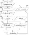
图14是表示使SCARA模式下的施加给第二关节部的侧倾轴的转矩最小的方法的一个例子的流程图;14 is a flowchart showing an example of a method of minimizing the torque applied to the roll axis of the second joint part in the SCARA mode;
图15是表示使SCARA模式下的施加给第二关节部的侧倾轴的转矩最小的方法的一个例子的流程图;15 is a flowchart showing an example of a method of minimizing the torque applied to the roll axis of the second joint part in the SCARA mode;
图16是表示在垂直模式的低处第三关节部的俯仰轴的转矩为最小的状态的一个例子的图;FIG. 16 is a diagram showing an example of a state in which the torque of the pitch axis of the lower third joint portion is the minimum in the vertical mode;
图17是表示在垂直模式的高处第三关节部的俯仰轴的转矩为最小的状态的一个例子的图;17 is a diagram showing an example of a state where the torque of the pitch axis of the third joint portion at a height in the vertical mode is the minimum;
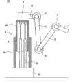
图18是表示本发明的实施方式4涉及的支承部的重力补偿机构的一个例子的图;18 is a diagram illustrating an example of a gravity compensation mechanism of a support portion according to
图19是表示本发明的实施方式4涉及的支承部的重力补偿机构的一个例子的图;19 is a diagram illustrating an example of a gravity compensation mechanism of a support portion according to
图20是表示本发明的实施方式5涉及的第二关节部的不可逆的动力传递机构的简要图;20 is a schematic diagram illustrating an irreversible power transmission mechanism of a second joint part according to
图21是表示与本发明的实施方式6涉及的支承部连结的移动体的一个例子的侧面图。FIG. 21 is a side view showing an example of a moving body connected to a support unit according to
具体实施方式Detailed ways
实施方式1.
以下,参照附图来说明本发明的实施方式。图1是表示本发明的实施方式1涉及的多关节型臂机器人的简要构成的立体图。另外,图2是表示本实施方式1涉及的多关节型臂机器人的简要臂构成的框图。并且,图3是表示本实施方式1涉及的多关节型臂机器人的简要的系统构成的框图。Hereinafter, embodiments of the present invention will be described with reference to the drawings. FIG. 1 is a perspective view showing a schematic configuration of an articulated arm robot according to
本实施方式1涉及的多关节型臂机器人10包括:支承部6,被固定在预定位置;第一臂部11,其一端经由第一关节部1与支承部6的上端连结;第二臂部12,其一端经由第三关节部3与第一臂部11的另一端连结;第三臂部13,其一端经由第四关节部4与第二臂部12的另一端连结;末端操纵部7,经由第五关节部5与第三臂部13的另一端连结;第一至第六驱动部21、22、23、24、25、26,分别使第一至第五关节部1、2、3、4、5旋转以及使支承部1伸缩;以及控制部8,控制第一至第六驱动部21、22、23、24、25、26的驱动。The articulated
支承部(铅垂升降轴)6具有能够向上下方向伸缩的伸缩机构,能够使与支承部6的上端连结的第一关节部1向上下方向移动,从而能够使臂全体向上下方向移动。第一臂部11的一端经由第一关节部1以能够绕横摆轴(肩轴1、水平转动轴)L1旋转的方式与支承部6连结。另外,在第一臂部11的两端间设置有能够绕侧倾轴(肩轴2)L2旋转的第二关节部2。The support part (vertical lift shaft) 6 has a telescopic mechanism capable of extending and contracting in the vertical direction, and can move the first
第二臂部12的一端经由第三关节部3以能够绕横摆轴或俯仰轴(肩轴3)L3旋转的方式与第一臂部11的另一端连结。第三臂部13的一端经由第四关节部4以能够绕横摆轴或俯仰轴(肘轴)L4旋转的方式与第二臂部12的另一端连结。末端操纵部7经由第五关节部5以能够绕侧倾轴(手腕轴1)L5、俯仰轴(手腕轴2)L6以及横摆轴(手腕轴3)L7旋转的方式与第三臂部13的另一端连结。One end of the
另外,第五关节部5的侧倾轴L5、俯仰轴L6以及横摆轴L7分别被配置成正交的三轴。由此,能够得到臂的反向运动学的解析解,因此可容易进行控制。末端操纵部7例如具有多个指部,构成为能够把持物体的把持部,但是不限于此,能够应用任意的构成。In addition, the roll axis L5, the pitch axis L6, and the yaw axis L7 of the fifth
第一至第五驱动部21、22、23、24、25例如是内置于第一至第五关节部1、2、3、4、5中的伺服马达等执行器,分别经由减速机构等旋转驱动第一至第五关节部1、2、3、4、5。第六驱动部26例如是内置于支承部6中的油压或电动执行器,使用伸缩机构使支承部6向上下方向伸缩。第一至第六驱动部21、22、23、24、25、26经由驱动电路等与控制部8连接,根据从控制部8发送的控制信号来旋转驱动第一至第五关节部1、2、3、4、5或者使支承部6伸缩。The first to
在第一至第五关节部1、2、3、4、5上分别设置有能够检测第一至第五关节部1、2、3、4、5的旋转角度的第一至第五旋转角传感器31、32、33、34、35。第一至第五旋转角传感器31、32、33、34、35例如是电位计,分别与控制部8连接,并向控制部8输出检测出的第一至第五关节部1、2、3、4、5的旋转角度。First to fifth rotation angles capable of detecting the rotation angles of the first to fifth
另外,第一旋转角传感器31能够检测第一关节部1绕横摆轴L1(#1)的旋转角度,第二旋转角传感器32能够检测第二关节部2绕侧倾轴L2(#2)的旋转角度,第三旋转角传感器33能够检测第三关节部3绕横摆轴或俯仰轴L3(#3)的旋转角度,第四旋转角传感器34能够检测第四关节部4绕横摆轴或俯仰轴L4(#4)的旋转角度,第五旋转传感器35能够分别检测第五关节部5绕侧倾轴L5(#5)、俯仰轴L6(#6)以及横摆轴L7(#7)的旋转角度。In addition, the first rotation angle sensor 31 can detect the rotation angle of the first
另外,在支承部6上设置有检测支承部6的高度位置(#O)的位置传感器36。位置传感器36与控制部8连接,向控制部8输出检测出的支承部6的高度位置。In addition, a position sensor 36 for detecting the height position (#0) of the
控制部8例如基于来自第一至第五旋转角传感器31、32、33、34、35的旋转角度进行反馈控制,以使第一至第五关节部1、2、3、4、5成为目标的旋转角度,或者基于来自位置传感器36的高度位置进行反馈控制,以使支承部6成为目标的高度位置。The control unit 8 performs feedback control based on the rotation angles from the first to fifth rotation angle sensors 31 , 32 , 33 , 34 , and 35 so that the first to fifth
另外,控制部8以微型计算机为中心通过硬件构成,所述微型计算机例如包括:进行控制处理、运算处理等的CPU(Central Processing Unit,中央处理器)8a,存储有由CPU 8a执行的控制程序、运算程序等的ROM(Read Only Memory,只读存储器)8b,以及存储处理数据等的RAM(Random Access Memory,随机存取存储器)8c等。In addition, the control unit 8 is constituted by hardware centering on a microcomputer, and the microcomputer includes, for example, a CPU (Central Processing Unit, central processing unit) 8a for performing control processing, calculation processing, etc., and stores a control program executed by the CPU 8a. ROM (Read Only Memory) 8b for computing programs, etc., and RAM (Random Access Memory) 8c for storing and processing data, etc.
控制部8将臂切换为使第一、第三以及第四关节部1、3、4仅在水平方向上旋转的SCARA模式(图4以及图5)以及使第三及第四关节部3、4仅在垂直方向上旋转的垂直模式(图6以及图7)来进行第一至第五关节部1、2、3、4、5的第一至第五驱动部21、22、23、24、25的驱动控制。The control unit 8 switches the arm to the SCARA mode ( FIG. 4 and FIG. 5 ) in which the first, third and fourth
第二关节部2的侧倾轴L2具有作为用于切换为SCARA模式和垂直模式的模式切换轴的功能。控制部8通过控制第二驱动部22使第二关节部2绕侧倾轴L2旋转,由此如上所述进行切换控制,以切换到第一、第三以及第四关节部1、3、4的旋转轴L1、L3、L4成为铅垂方向的SCARA模式和第三及第四关节部3、4的旋转轴L3、L4成为水平方向的垂直模式。以下,详细说明SCARA模式以及垂直模式。The roll axis L2 of the second
(SCARA模式)(SCARA mode)
控制部8当使第二关节部2绕侧倾轴L2旋转而将臂切换为SCARA模式(图4以及图5)时,经由第一、第三以及第四驱动部21、23、24来控制第一、第三以及第四关节部1、3、4的水平方向的旋转,并控制臂姿势。由此,例如,能够在重量物的把持、运送作业时等,有效地减轻施加给根部的关节轴(尤其是,第二关节部2的侧倾轴L2)的负荷。When the control unit 8 rotates the second
这里,在SCARA模式中,由臂和工件的重力产生的负荷作用于支承部6、第二关节部2、以及第五关节部5。另一方面,第五关节部5的力矩长度短、其力矩力小,驱动第五关节部5的第五驱动部25的驱动力能够较低地抑制。另外,第二关节部2如后面所述能够较低地抑制驱动力,另一方面支承部6的伸缩需要大的驱动力,然而对于支承部6的驱动力,也如后面所述,通过使用重力补偿机构61,即使是低驱动力也能够产生大的伸缩力。这样,控制部8通过将臂切换为SCARA模式,能够以低驱动力且低消耗电力来驱动臂。Here, in the SCARA mode, loads due to gravity of the arm and the workpiece act on the
另外,在SCARA模式中,第五关节部5的上下方向的位置仅根据支承部6的高度位置来确定,因此根据支承部6的上下方向的伸缩范围来确定第五关节部5的上下可动区域(图8)。因此,例如优选主要以在桌上作业这样的中间左右的高度进行作业。In addition, in the SCARA mode, the vertical position of the fifth
(垂直模式)(vertical mode)
控制部8当使第二关节部2绕侧倾轴L2旋转来将臂切换为垂直模式时(图6以及图7),经由第三以及第四驱动部23、24来控制第三以及第四关节部3、4的垂直方向的旋转,并控制臂姿势。由此,例如,能够进行位于低处或高处的物体的把持、运送作业等的大可动区域的臂动作。When the control unit 8 rotates the second
例如,在诸如地板上的低处,控制部8在经由第六驱动部26使支承部6收缩而降低了第一关节部1的状态下,将臂切换为垂直模式,使末端操纵部7移动到第一至第三关节部(肩轴1至3)1、2、3的下侧来进行作业(图9)。For example, at a low place such as on the floor, the control unit 8 switches the arm to the vertical mode in a state where the
另一方面,在诸如支架上的高处,控制部8在经由第六驱动部26使支承部6伸长而提高了第一关节部1的状态下,将臂切换为垂直模式,使末端操纵部7移动到第一至第三关节部(肩轴1至3)1、2、3的上侧来进行作业(图10)。这样,控制部8将臂从SCARA模式切换为垂直模式,由此能够将末端操纵部7的可动区域从低处到高处在大范围内运动(图11)。On the other hand, at a high place such as on a stand, the control unit 8 switches the arm to the vertical mode in a state where the
另外,在垂直模式下,第三及第四关节部3、4绕俯仰轴L3、L4旋转,因此容易作用由重力产生的负荷,与SCARA模式相比可运重量变小。因此,低处或高处(图11的区域X)的作业以不把持超过最大驱动转矩的重量物为前提。这样,控制部8能够通过切换为垂直模式使臂在从低处至高处的大范围移动而进行作业。In addition, in the vertical mode, since the third and fourth
另外,控制部8通过将臂切换为垂直模式来控制第三及第四关节部3、4的旋转,以收存第二臂部12、第三臂部13以及末端操纵部7(图12的(a)以及(b))。例如,控制部8将臂切换为垂直模式,使第三关节部3旋转,以使第二臂部12成为铅垂向下方向,使第四关节部4旋转,以使第三臂部13成为铅垂向上方向。In addition, the control part 8 controls the rotation of the third and fourth
这里,第二臂部12和第三臂部13如图12(a)及(b)所示,通过以在臂收存时使第四关节部4旋转时不相互干涉的方式构成各臂,从而能够更紧凑地收存。Here, the
在通常的SCARA型臂中,第二臂部在臂收存时从第三关节部的位置水平突出大于等于第二臂部的长度,因此臂机器人全体的占地面积(地面投影面积)变大。另一方面,根据本实施方式1涉及的多关节型臂机器人10,通过将臂切换为垂直模式,并折叠各臂,从而能够减小在收存了各臂的状态下的占地面积。这样,能够在具有SCARA型臂的优点的同时改善作为其缺点的收存性。In a normal SCARA-type arm, the second arm protrudes horizontally from the position of the third joint when the arm is stored. The length of the second arm is greater than or equal to the length of the second arm. Therefore, the footprint (ground projected area) of the arm robot as a whole becomes large. . On the other hand, according to the articulated
以上,在本实施方式1涉及的多关节型臂机器人10中,控制部8通过将臂切换为使第一、第三以及第四关节部1、3、4仅在水平方向上旋转的SCARA模式和使第三以及第四关节部3、4仅在垂直方向上旋转的垂直模式,来进行第一至第四关节部1、2、3、4的第一至第四驱动部21、22、23、24的驱动控制。由此,能够在SCARA模式下以低驱动力驱动臂,能够在垂直模式下使臂在大范围内移动。As described above, in the articulated
另外,在第一臂部11上在两端间设置第二关节部2,使该第二关节部2绕侧倾轴L2旋转,从而能够容易实现SCARA模式和垂直模式的切换。即,能够通过简单的构成来提供以低驱动力驱动臂并且使臂在大范围内移动的多关节型臂机器人10。In addition, the second
实施方式2.
在本发明的实施方式2涉及的多关节型臂机器人10中,控制部8在SCARA模式下控制第一、第三以及第四驱动部21、23、24,来控制第一、第三以及第四关节部1、3、4的旋转,以使施加给第二关节部2的侧倾轴L2的转矩最小。在SCARA模式下,容易对第二关节部2的侧倾轴L2作用大的转矩,但是通过使该第二关节部2的转矩最小化,能够采用低驱动力的第二驱动部22,从而能够提高臂的安全性以及实现低消耗电力化。In the articulated
例如,控制部8控制第一、第三以及第四驱动部21、23、24,来控制第一、第三以及第四关节部1、3、4的旋转,以使基于从第二关节部2至末端操纵部7的重心位置G的力矩力(力矩长度X1)最小(图13)。For example, the control part 8 controls the first, third and fourth drive parts 21, 23, 24 to control the rotation of the first, third and fourth
接着,对如上所述在SCARA模式下使施加给第二关节部2的侧倾轴L2的转矩为最小的方法的一个例子进行详细说明。图14是表示使本实施方式2涉及的SCARA模式下的施加给第二关节部的侧倾轴的转矩为最小的方法的一个例子的流程图。Next, an example of a method for minimizing the torque applied to the roll axis L2 of the second
首先,控制部8设定末端操纵部7的目标位置姿势、即目标手尖位置姿势(步骤S101)。接着,控制部8使用冗余自由度参数进行公知的反向运动学运算,以使臂成为设定的目标手尖位置姿势(步骤S102),并计算出第一至第五关节部1、2、3、4、5的目标旋转角度(步骤S103)。First, the control unit 8 sets the target position and posture of the
这里,在上述反向运动学运算中,例如,将第一关节部1的旋转角度设定为冗余自由度参数并作为常数处理,第二关节部2在SCARA模式的状态下被固定,因此本实施方式2涉及的臂构成包含升降轴在内是8轴,但是可以视为6轴臂,如果将第五关节部5设为正交三轴,则能够得到反向运动学的解析解。Here, in the above-mentioned inverse kinematics calculation, for example, the rotation angle of the first
之后,控制部8基于预先设定的第一至第三臂部11、12、13以及末端操纵部7的重量参数以及计算出的第一至第五关节部1、2、3、4、5的目标旋转角度来进行公知的正向运动学运算(步骤S104),并计算出从第二关节部2到末端操纵部7的重心位置G(步骤S105)。Afterwards, the control unit 8 based on the preset weight parameters of the first to
另外,控制部8计算出包括第二关节部2的侧倾轴L2的铅垂平面S1(步骤S106)。另外,重量参数例如被预先设定在控制部8的ROM 8b或RAM 8c中。In addition, the control unit 8 calculates a vertical plane S1 including the roll axis L2 of the second joint unit 2 (step S106 ). In addition, the weight parameter is preset in, for example, the ROM 8b or RAM 8c of the control unit 8.
另外,控制部8计算出从计算出的第二关节部2到末端操纵部7的重心位置G与包括第二关节部2的侧倾轴L2的铅垂平面S1的距离(力矩长度)X1〔图13)(步骤S107)。In addition, the control unit 8 calculates the distance (moment length) X1 from the calculated second
控制部8通过牛顿法等收敛运算法改变冗余自由度的参数,并进行设定,以使从第二关节部2到末端操纵部7的重心位置G与包括第二关节部2的侧倾轴L2的铅垂平面S1的距离X1为最小(步骤S108),并返回到上述(步骤S102)。The control unit 8 changes the parameters of the redundant degrees of freedom by a convergent algorithm such as Newton's method, and sets them so that the center of gravity position G from the second
另外,控制部8例如通过对工件重量预先模型化,或者在工件把持后使用载荷传感器等进行检测,来修正上述重量参数,从而能够更高精度地计算出重心位置G。In addition, the control unit 8 can calculate the center-of-gravity position G more accurately by correcting the above-mentioned weight parameters by, for example, modeling the workpiece weight in advance or detecting it with a load sensor after gripping the workpiece.
另外,控制部8也可以基于由转矩传感器等测量出的第二关节部2的侧倾轴L2的转矩来使SCARA模式下施加给第二关节部2的侧倾轴L2的负荷转矩最小。由此,即使是在难以通过力传感器等直接测量工件重量或与环境的接触力等作用于臂的外力的情况下,也能够容易降低施加给第二关节部2的侧倾轴L2的负荷转矩。In addition, the control unit 8 may set the load torque applied to the roll axis L2 of the second
在此情况下,如图15所示,首先,控制部8设定末端操纵部7的目标位置,设定目标手尖位置姿势(步骤S201)。接着,控制部8使用冗余自由度参数进行公知的反向运动学运算,以使臂姿势成为设定的目标手尖位置姿势(步骤S202),并计算出第一至第五关节部1、2、3、4、5的旋转角度指令值(步骤S203)。In this case, as shown in FIG. 15 , first, the control unit 8 sets the target position of the
控制部8对第一至第五驱动部21、22、23、24、25输出计算出的第一至第五关节部1、2、3、4、5的旋转角度指令值,第一至第五驱动部21、22、23、24、25根据来自控制部8的第一至第五关节部1、2、3、4、5的旋转角度指令值分别使第一至第五关节部1、2、3、4、5旋转(步骤S204)。The control unit 8 outputs the calculated rotation angle command values of the first to fifth
第二关节部2的转矩传感器检测出施加给第二关节部2的侧倾轴L2的转矩(步骤S205),并对控制部8输出检测出的转矩。The torque sensor of the second
控制部8设定冗余自由度参数,以使施加给第二关节部2的侧倾轴L2的转矩变小(步骤S206),并返回到上述(步骤S202)。另外,对在SCARA模式下使施加给第二关节部2的侧倾轴L2的转矩最小化的方法进行了说明,但是上述方法是一个例子,不限于此,可以使用任意的方法来求出。The control part 8 sets the redundant degree of freedom parameter so that the torque applied to the roll axis L2 of the second
以上,根据本实施方式2涉及的多关节型臂机器人10,在SCARA模式下,成为对作为臂基部的第二关节部2容易作用大的转矩的状态,但是控制部8如上所述控制第一、第三以及第四关节部1、3、4的旋转,以使施加给第二关节部2的侧倾轴L2的转矩最小。由此,能够采用低驱动力的第二驱动部22,因此能够实现安全且低消耗电力的臂构成。As described above, according to the articulated
实施方式3.
在本发明的实施方式3涉及的多关节型臂机器人10中,控制部8在垂直模式下控制第三以及第四驱动部23、24,来控制第三以及第四关节部3、4的旋转,以使得施加给第三关节部3的俯仰轴L3的转矩最小。在垂直模式下,容易对第三关节部3作用大的转矩,但是通过使该第三关节部3的转矩最小化,能够采用低驱动力的第三驱动部23,从而能够提高臂的安全性以及实现低消耗电力化。In the articulated
例如,控制部8选择以第三关节部3的俯仰轴L3为中心的、基于从第三关节部3到末端操纵部7的重心位置G的力矩力(力矩长度X2)更小的反向运动学的解,来控制第三以及第四驱动部23、24,从而控制第三以及第四关节部3、4的旋转。For example, the control unit 8 selects a reverse movement centered on the pitch axis L3 of the third
更简单地说,控制部8在第三关节部3为比第四以及第五关节部4、5高的低处姿势的情况下,控制第三以及第四关节部3、4的旋转,以使第四关节部4相对于第三关节部3与第五关节部5的连线位于下侧(图16)。More simply, the control unit 8 controls the rotation of the third and fourth
另一方面,控制部8在第三关节部3为比第四以及第五关节部4、5低的高处姿势的情况下,控制第三以及第四关节部3、4的旋转,以使第四关节部4相对于第三关节部3与第五关节部5的连线位于上侧(图17)。On the other hand, the control unit 8 controls the rotation of the third and fourth
以上,根据本实施方式3涉及的多关节型臂机器人10,在垂直模式下,成为容易对作为臂基部的第三关节部3作用大的转矩的状态,但是控制部8如上所述控制第三以及第四关节部3、4的旋转,以使施加给第三关节部3的俯仰轴L3的转矩最小,由此能够采用低驱动力的第三驱动部23,因此能够实现安全且低消耗电力的臂构成。As described above, according to the articulated
实施方式4.
在本发明的实施方式4涉及的多关节型臂机器人10中,支承部6可以具有支承从第一关节部1到末端操纵部7的重力的重力补偿机构41。在臂基部的支承部6的伸缩上需要大的驱动力,但是通过在支承部6上设置重力补偿机构41,由此从第一关节部1到末端操纵部7的重力始终由重力补偿机构41支承,使支承部6以应对近似有效作业力的必要最小限度的驱动力进行伸缩即可。即,能够对支承部6的伸缩采用低驱动力的第六驱动部26,从而能够提高臂的安全性以及实现低消耗电力化。In the articulated
例如,支承部6具有固定于预定位置的基座42、与基座42连结固定的下侧部件43、以及以能够在上下方向上移动的方式与下侧部件43卡合的上侧部件44(图18)。在下侧以及上侧部件43、44内,使上侧部件44相对于下侧部件43在上下方向上相对移动的直动执行器(第六驱动部)26沿其长度方向设置。另外,在下侧以及上侧部件43、44内,通过与从第一关节部2到末端操纵部7的重力同等的力始终对上侧部件44向上方施力的气簧(重力补偿机构)41相对于直动执行器26并列设置。For example, the
另外,作为重力补偿机构41例如可以使用气簧,但是不限于此,例如可以是使用了配重的构成,只要能够支承从第一关节部1到末端操纵部7作用的重力,则可以使用任意的机构。In addition, as the
实施方式5.
在本发明的实施方式5涉及的多关节型臂机器人10中,可以在第二关节部21上设置不可逆的动力传递机构51,所述动力传递机构51将来自第二驱动部22侧的输出转矩向第二关节部2的侧倾轴L2侧传递,并且不将来自第二关节部2的侧倾轴L2侧的转矩向第二驱动部22侧传递(图20)。作为不可逆的动力传递机构51,例如可以使用转矩二极管(torquediode)(注册商标)或蜗轮等来防止逆驱动。In the articulated
尤其是,在SCARA模式下,容易对作为臂基部的第二关节部2作用大的转矩,但是仅在SCARA模式和垂直模式的模式切换动作时驱动作为驱动模式切换轴的第二关节部2的侧倾轴L2。并且,在模式切换后,通过不可逆的动力传递机构51来保持来自第二关节部2的侧倾轴L2的臂重力和由工件作业产生的外力,从而即使是在没有第二驱动部22的驱动力的状态下,也能够维持模式切换后的臂姿势。由此,第二驱动部22可仅输出模式切换动作所需的驱动力即可。因此,能够采用低驱动力的第二驱动部22,能够实现安全且低消耗电力的臂构成。In particular, in the SCARA mode, a large torque tends to act on the second
例如,在第二关节部2中,减速器52的输入轴与作为第二驱动部22的伺服马达的输出轴连结,不可逆的动力传递机构51的输入轴与减速器52的输出轴连结,第二关节部2的侧倾轴L2与不可逆的动力传递机构51的输出轴连结。For example, in the second
根据该构成,即使在第二驱动部22的输出轴不旋转的状态下产生了来自第二关节部2的侧倾轴L2的臂重力和由工件作业产生的外力,第二关节部2的侧倾轴L2也可由不可逆的动力传递机构51锁定。因此,即使第二驱动部22的驱动力是零,也能够保持第二关节部2的侧倾轴L2的旋转角度。另外,也可以在不可逆的动力传递机构51的允许输入转速大于减速器52的输入轴的最高转速的情况下,颠倒减速器52和不可逆的动力传递机构51的组装顺序。另外,不可逆的动力传递机构51是设置在第二关节部2的侧倾轴L2上的构成,另外也可以是设置在第三关节部3的横摆轴或俯仰轴L3和/或第四关节部4的横摆轴或俯仰轴L4的构成。According to this configuration, even if the arm weight force from the roll axis L2 of the second
实施方式6.
本发明的实施方式6涉及的多关节型臂机器人10也可以具有与支承部6连结并可移动的移动体61(图21)。作为移动体61,例如构成为具有多个车轮62的底盘部61,但是不限于此,可以使用任意的构成。The articulated
由此,即使是在把持、操作对象物不存在于地面、桌上、支架上等臂的到达范围的情况下,也能够将移动体61移动到可作业的场所,能够进行把持等并运送,因此能够进行大范围内的物品的把持、搬送。即,能够通过简单的构成以低驱动力驱动臂并且使臂在大范围内移动。Thus, even when the object to be grasped or operated does not exist within the reach of the arm, such as on the ground, on a table, or on a stand, the
另外,本发明不限于上述实施方式,可以在不脱离主旨的范围内酌情改变。In addition, this invention is not limited to the said embodiment, It can change suitably in the range which does not deviate from the main point.
在上述的实施方式中,将本发明作为硬件的构成进行了说明,但是本发明不限于此。本发明也可以通过使CPU 8a执行计算机程序来实现控制部8执行的处理。In the above-mentioned embodiments, the present invention has been described as a hardware configuration, but the present invention is not limited thereto. In the present invention, the processing performed by the control unit 8 can also be realized by causing the CPU 8a to execute a computer program.
程序可使用各种类型的非临时性的计算机可读介质(non-transitorycomputer readable medium)存储而提供给计算机。非临时性的计算机可读介质包括各种类型的实体记录介质(tangible storage medium)。非临时的计算机可读介质的例子包括磁记录介质(例如,软盘、磁带、硬盘驱动器)、光磁记录介质(例如,光磁盘)、CD-ROM(Read Only Memory,只读存储器)、CD-R、CD-R/W、半导体存储器(例如,掩模ROM、PROM(Programmable ROM,可编程只读存储器)、EPROM(ErasablePROM,可擦可编程序只读存储器)、闪存(flash ROM)、RAM(random access memory,随机存取存储器)。The program can be stored and provided to the computer using various types of non-transitory computer readable medium (non-transitory computer readable medium). Non-transitory computer readable media include various types of tangible storage media. Examples of non-transitory computer-readable media include magnetic recording media (e.g., floppy disks, tapes, hard drives), optical-magnetic recording media (e.g., optical disks), CD-ROMs (Read Only Memory), CD- R, CD-R/W, semiconductor memory (for example, mask ROM, PROM (Programmable ROM, programmable read-only memory), EPROM (Erasable PROM, erasable programmable read-only memory), flash memory (flash ROM), RAM (random access memory, random access memory).
另外,程序可以通过各种类型的临时性的计算机可读介质(transitorycomputer readable medium)提供给计算机。临时性的计算机可读介质的例子包括电信号、光信号、以及电磁波。临时性的计算机可读介质经由电线以及光纤等有线通信路或无线通信路将程序提供给计算机。In addition, the program can be provided to the computer through various types of transitory computer readable medium (transitory computer readable medium). Examples of transitory computer readable media include electrical signals, optical signals, and electromagnetic waves. The transitory computer-readable medium provides the program to the computer via wired communication channels such as electric wires and optical fibers, or wireless communication channels.
产业上的利用可能性Industrial Utilization Possibility
本发明例如可以应用于与人共处并进行使人或物等移动的作业的机器人臂。The present invention can be applied to, for example, a robot arm that lives with a human being and performs work for moving a human being or an object.
符号说明Symbol Description
1 第一关节部1 first joint
2 第二关节部2 second joint
3 第三关节部3 third joint
4 第四关节部4 fourth joint
5 第五关节部5 fifth joint
6 支承部6 Supporting part
7 末端操纵部77
8 控制部8 Control Department
10 多关节型臂机器人10 articulated arm robot
11 第一臂部11 first arm
12 第二臂部12 second arm
13 第三臂部13 Third arm
21 第一驱动部21 First drive unit
22 第二驱动部22 Second drive unit
23 第三驱动部23 The third driving unit
24 第四驱动部24 Fourth drive unit
25 第五驱动部25 fifth driving unit
26 第六驱动部26 Sixth drive unit
Claims (16)
Applications Claiming Priority (1)
| Application Number | Priority Date | Filing Date | Title |
|---|---|---|---|
| PCT/JP2011/000523WO2012104895A1 (en) | 2011-01-31 | 2011-01-31 | Multi-joint arm robot, control method, and control program |
Publications (2)
| Publication Number | Publication Date |
|---|---|
| CN103328161Atrue CN103328161A (en) | 2013-09-25 |
| CN103328161B CN103328161B (en) | 2015-08-19 |
Family
ID=46602151
Family Applications (1)
| Application Number | Title | Priority Date | Filing Date |
|---|---|---|---|
| CN201180004631.5AExpired - Fee RelatedCN103328161B (en) | 2011-01-31 | 2011-01-31 | Multi-joint arm robot and control method thereof |
Country Status (5)
| Country | Link |
|---|---|
| US (1) | US8442686B2 (en) |
| EP (1) | EP2671689B1 (en) |
| JP (1) | JP5146621B2 (en) |
| CN (1) | CN103328161B (en) |
| WO (1) | WO2012104895A1 (en) |
Cited By (23)
| Publication number | Priority date | Publication date | Assignee | Title |
|---|---|---|---|---|
| CN104290098A (en)* | 2014-08-15 | 2015-01-21 | 东莞市均利自动化科技有限公司 | An automatic control method and multi-axis control device based on multi-axis linkage |
| CN104624517A (en)* | 2013-11-13 | 2015-05-20 | 航天信息股份有限公司 | Manipulator-type automatic grain sorting device |
| CN104786216A (en)* | 2014-01-17 | 2015-07-22 | 斗山重工业株式会社 | Multi-articulated manipulator |
| CN106217369A (en)* | 2016-08-10 | 2016-12-14 | 蚌埠市多宝塑模科技有限公司 | A kind of robot device |
| CN104090492B (en)* | 2014-07-14 | 2017-02-01 | 江南大学 | SCARA robot PTP trajectory planning method based on exponential function |
| CN107435720A (en)* | 2017-09-07 | 2017-12-05 | 吴烈 | Driving joint, power arm and Versatile Construction Machinery |
| CN107443355A (en)* | 2017-08-04 | 2017-12-08 | 国网山东省电力公司电力科学研究院 | A kind of mechanical arm and control method for partial discharge of switchgear detection |
| CN107520841A (en)* | 2017-09-29 | 2017-12-29 | 英华达(上海)科技有限公司 | The robot and its control method of the variable number of axle |
| TWI616290B (en)* | 2016-07-06 | 2018-03-01 | 英華達股份有限公司 | Multiaxial robot of multitasking and operating method thereof |
| CN109483582A (en)* | 2018-11-30 | 2019-03-19 | 商丘师范学院 | A kind of forearm is equipped with the robot of mechanical arm assembly |
| CN109531535A (en)* | 2018-12-26 | 2019-03-29 | 襄阳国铁机电股份有限公司 | A kind of high-sided wagon vehicle door disassembling device |
| CN109571422A (en)* | 2017-09-28 | 2019-04-05 | 发那科株式会社 | Robot |
| CN109571425A (en)* | 2017-09-28 | 2019-04-05 | 发那科株式会社 | Industrial machinery and its shifting set mechanism |
| CN110167719A (en)* | 2016-11-14 | 2019-08-23 | 库卡德国有限公司 | Robots arm, mobile robot and logistics system |
| CN110282049A (en)* | 2018-03-19 | 2019-09-27 | 戴弗根特技术有限公司 | Vehicles manufacture system and method based on manufacturing cell |
| TWI689389B (en)* | 2016-08-09 | 2020-04-01 | 英華達股份有限公司 | Multiaxial robot |
| TWI691152B (en)* | 2018-09-27 | 2020-04-11 | 台達電子工業股份有限公司 | Robot system |
| CN111185893A (en)* | 2020-03-09 | 2020-05-22 | 辽宁科技大学 | A master-slave manipulator that can act synchronously |
| US10814502B2 (en) | 2018-09-27 | 2020-10-27 | Delta Electronics, Inc. | Robotic system |
| CN111941403A (en)* | 2019-05-17 | 2020-11-17 | 本田技研工业株式会社 | Chain link mechanism, its control device and control method |
| US11065760B2 (en) | 2016-08-09 | 2021-07-20 | Inventec Appliances (Pudong) Corporation | Multiaxial robot with cover |
| CN115741680A (en)* | 2022-11-03 | 2023-03-07 | 三峡大学 | Multi-degree-of-freedom mechanical arm system based on laser guidance and visual assistance and hole accurate positioning method |
| CN116175529A (en)* | 2022-07-12 | 2023-05-30 | 上海奔曜科技有限公司 | Seven-axis robot |
Families Citing this family (74)
| Publication number | Priority date | Publication date | Assignee | Title |
|---|---|---|---|---|
| US10383765B2 (en) | 2012-04-24 | 2019-08-20 | Auris Health, Inc. | Apparatus and method for a global coordinate system for use in robotic surgery |
| CN102914284B (en)* | 2012-10-19 | 2015-07-08 | 中铁隧道集团有限公司 | Real-time measurement system for work position of operation arm and measurement method thereof |
| CN103009383B (en)* | 2012-12-11 | 2015-04-22 | 江苏大学 | Telescopic PRRRPR type manipulator for picking robots |
| JP6086440B2 (en)* | 2013-01-31 | 2017-03-01 | 国立大学法人佐賀大学 | Operation support device |
| JP2014151369A (en)* | 2013-02-05 | 2014-08-25 | Seiko Epson Corp | robot |
| US9842757B2 (en)* | 2013-06-05 | 2017-12-12 | Persimmon Technologies Corporation | Robot and adaptive placement system and method |
| KR101445107B1 (en) | 2013-06-07 | 2014-10-02 | 첨단기공 주식회사 | Robot capable of mounting and disassembling the nozzle dam of steam generator without interference in the nuclear reactor |
| US9745081B2 (en)* | 2013-07-12 | 2017-08-29 | The Boeing Company | Apparatus and method for moving a structure in a manufacturing environment |
| FR3008576B1 (en)* | 2013-07-17 | 2016-02-05 | Kuhn Sa | PERFECTED FODDER HARVESTING MACHINE |
| GB2523831B (en)* | 2014-03-07 | 2020-09-30 | Cmr Surgical Ltd | Surgical arm |
| EP3186069B1 (en)* | 2014-08-28 | 2023-06-07 | Skogsrud, Simen Svale | 3d printer |
| CN107073707B (en) | 2014-09-30 | 2021-06-04 | 精工爱普生株式会社 | robot |
| US10499999B2 (en) | 2014-10-09 | 2019-12-10 | Auris Health, Inc. | Systems and methods for aligning an elongate member with an access site |
| CN107107336B (en)* | 2014-11-18 | 2021-04-02 | 柿子技术公司 | Robot adaptive placement system with end effector position estimation |
| JP6398833B2 (en)* | 2015-03-27 | 2018-10-03 | 株式会社デンソー | Body support follower |
| JP6582491B2 (en)* | 2015-03-31 | 2019-10-02 | セイコーエプソン株式会社 | robot |
| DE202015101621U1 (en) | 2015-03-31 | 2016-07-04 | Kuka Systems Gmbh | working device |
| GB2538497B (en) | 2015-05-14 | 2020-10-28 | Cmr Surgical Ltd | Torque sensing in a surgical robotic wrist |
| DE102015009048B3 (en)* | 2015-07-13 | 2016-08-18 | Kuka Roboter Gmbh | Controlling a compliant controlled robot |
| CN108025445A (en)* | 2015-07-23 | 2018-05-11 | 斯里国际 | Robots arm and robotic surgical system |
| DE102015113467A1 (en)* | 2015-08-14 | 2017-02-16 | Sami Haddadin | Robotic arm and robot wrist |
| CN105058377A (en)* | 2015-08-18 | 2015-11-18 | 重庆华数机器人有限公司 | Five-shaft swing arm joint robot |
| JP6546484B2 (en)* | 2015-09-01 | 2019-07-17 | 株式会社河合楽器製作所 | Grand piano large roof support device |
| US20190125480A1 (en)* | 2015-10-07 | 2019-05-02 | Intuitive Surgical Operations, Inc. | Roll control based on pitch and yaw inputs for a device in a computer-assisted medical system |
| WO2017062370A1 (en)* | 2015-10-07 | 2017-04-13 | Intuitive Surgical Operations, Inc. | Controlling roll for a device in a computer-assisted medical system |
| CN105328702B (en)* | 2015-10-13 | 2017-12-12 | 深圳市桑谷医疗机器人有限公司 | Multiple shaft lifting extracts and injection of medicine manipulator |
| KR101734241B1 (en)* | 2015-12-10 | 2017-05-11 | 현대자동차 주식회사 | Trunk lid hinge intellectual loader unit |
| CA3005265A1 (en)* | 2015-12-31 | 2017-07-06 | Counsyl, Inc. | Robotic system for sorting sample tubes |
| JP6686644B2 (en)* | 2016-04-06 | 2020-04-22 | セイコーエプソン株式会社 | Robots and robot systems |
| US20180258683A1 (en)* | 2016-05-27 | 2018-09-13 | John Wellman | Truck Hopper Gate Opener |
| US10580681B2 (en)* | 2016-07-10 | 2020-03-03 | Yaskawa America Inc. | Robotic apparatus and method for transport of a workpiece |
| JP6457441B2 (en)* | 2016-07-12 | 2019-01-23 | ファナック株式会社 | Robot center-of-gravity display device, robot control device, and robot simulation device |
| CN106217345B (en)* | 2016-08-31 | 2018-04-24 | 北京术锐技术有限公司 | The flexible Continuum Structure of gesture feedback can be achieved |
| DE102016216902A1 (en)* | 2016-09-06 | 2018-03-08 | Deckel Maho Pfronten Gmbh | Machine tool for machining a workpiece and spindle carrier assembly for use on such a machine tool |
| US10737817B2 (en) | 2016-09-26 | 2020-08-11 | Yaskawa America, Inc. | Method, apparatus, and system for robotic article handling |
| US11173003B2 (en) | 2017-01-10 | 2021-11-16 | Intuitive Surgical Operations, Inc. | Systems and methods for using a robotic medical system |
| KR102219543B1 (en)* | 2017-04-26 | 2021-02-24 | 니혼 덴산 가부시키가이샤 | Articulated robot and articulated robot system |
| WO2019005696A1 (en) | 2017-06-28 | 2019-01-03 | Auris Health, Inc. | Electromagnetic distortion detection |
| CN116725667A (en) | 2017-06-28 | 2023-09-12 | 奥瑞斯健康公司 | System for providing positioning information and method for positioning an instrument within an anatomical structure |
| JP2017185625A (en)* | 2017-07-13 | 2017-10-12 | セイコーエプソン株式会社 | robot |
| CN107320179B (en)* | 2017-08-18 | 2023-07-14 | 深圳先进技术研究院 | A Posture Adjustment Mechanism and a Master Manipulator for Series Minimally Invasive Surgery |
| US10464209B2 (en) | 2017-10-05 | 2019-11-05 | Auris Health, Inc. | Robotic system with indication of boundary for robotic arm |
| AU2018346790B2 (en) | 2017-10-05 | 2024-09-26 | Mobius Imaging, Llc | Methods and systems for performing computer assisted surgery |
| US10016900B1 (en) | 2017-10-10 | 2018-07-10 | Auris Health, Inc. | Surgical robotic arm admittance control |
| CN109693233B (en)* | 2017-10-20 | 2020-11-24 | 深圳市优必选科技有限公司 | Robot posture detection method and device, terminal equipment and computer storage medium |
| CN107803842A (en)* | 2017-10-23 | 2018-03-16 | 深圳智英电子有限公司 | A kind of top box of digital machine board aging charging manipulator |
| CN107825396B (en)* | 2017-11-10 | 2023-10-20 | 广东电网有限责任公司东莞供电局 | Robot for carrying high-voltage porcelain insulator in electric power operation |
| JP7151072B2 (en)* | 2017-11-15 | 2022-10-12 | セイコーエプソン株式会社 | robot |
| CN108420533B (en)* | 2018-03-09 | 2024-08-20 | 山东大学齐鲁医院 | Single-hole surgical robot integral layout structure with movable and autorotation positioning joints |
| JP7087575B2 (en)* | 2018-03-30 | 2022-06-21 | 日本電産株式会社 | Posture adjustment method for 6-axis robot |
| JP2019177436A (en)* | 2018-03-30 | 2019-10-17 | 日本電産株式会社 | Robot control device, method for determining angle of joint of robot, and program |
| CN108673484A (en)* | 2018-07-09 | 2018-10-19 | 原敏虎 | A kind of universal mechanical arm |
| CN109238470A (en)* | 2018-10-30 | 2019-01-18 | 合肥京东方视讯科技有限公司 | Temperature testing device, Research on Automatic Measuring System of Temperature and temperature testing method |
| JP7516403B2 (en)* | 2019-02-08 | 2024-07-16 | ヤスカワ アメリカ インコーポレイティッド | Through beam automatic teaching |
| CN109822558A (en)* | 2019-03-12 | 2019-05-31 | 哈尔滨理工大学 | A practical engineering manipulator |
| JP2020163548A (en)* | 2019-03-29 | 2020-10-08 | セイコーエプソン株式会社 | Horizontal articulated robots and robot systems |
| JP7207094B2 (en)* | 2019-03-29 | 2023-01-18 | セイコーエプソン株式会社 | Horizontal articulated robot |
| CN109946307B (en)* | 2019-03-29 | 2023-10-20 | 北京城建五建设集团有限公司 | Telescopic electric steering inspection mirror and application method thereof |
| US11607804B2 (en)* | 2019-05-28 | 2023-03-21 | X Development Llc | Robot configuration with three-dimensional lidar |
| US11235459B2 (en)* | 2019-08-15 | 2022-02-01 | Intrinsic Innovation Llc | Inverse kinematic solver for wrist offset robots |
| EP4025921A4 (en) | 2019-09-03 | 2023-09-06 | Auris Health, Inc. | DETECTION AND COMPENSATION OF ELECTROMAGNETIC DISTORTION |
| US11254015B2 (en) | 2019-09-24 | 2022-02-22 | Thermo Crs Ltd. | Multi-axis gripper for lab automation robot |
| JP2021062443A (en)* | 2019-10-11 | 2021-04-22 | セイコーエプソン株式会社 | Teaching method |
| CN110979059B (en)* | 2019-11-27 | 2022-08-02 | 长安大学 | Electric truck arm and device that charges |
| CN110956748A (en)* | 2019-12-13 | 2020-04-03 | 广州翌日动漫设计有限公司 | Mechanical arm for gift machine and using method thereof |
| CN113288427B (en)* | 2020-02-21 | 2022-07-05 | 中国科学院沈阳自动化研究所 | A suspension positioning manipulator and its control method |
| JP6886060B2 (en)* | 2020-04-03 | 2021-06-16 | ファナック株式会社 | robot |
| US11685043B2 (en)* | 2020-05-09 | 2023-06-27 | Ubtech Robotics Corp Ltd | Mechanical arm |
| CN114623355A (en)* | 2020-12-10 | 2022-06-14 | 中国科学院沈阳自动化研究所 | Lifting system with rotation pitching function |
| CN112755463A (en)* | 2021-01-22 | 2021-05-07 | 景枢(上海)科技有限公司 | Body-building apparatus |
| EP4329987A4 (en)* | 2021-04-28 | 2024-10-09 | Apptronik, Inc. | Deployable robotic arm |
| WO2023074140A1 (en)* | 2021-10-28 | 2023-05-04 | ソニーグループ株式会社 | Distal-end wrist device and robot arm device |
| CN114469356B (en)* | 2022-01-24 | 2023-09-15 | 重庆金山医疗机器人有限公司 | Driving method of master hand and surgical robot doctor control console |
| US20240269828A1 (en)* | 2023-02-11 | 2024-08-15 | Ghost Robotics Corporation | Decoupled Wrist-Agnostic Control for Modular Robotic Arm |
Citations (5)
| Publication number | Priority date | Publication date | Assignee | Title |
|---|---|---|---|---|
| JPS61252084A (en)* | 1985-05-01 | 1986-11-10 | 株式会社 アマダ | Master/slave type robot |
| WO2001030544A1 (en)* | 1999-10-28 | 2001-05-03 | Kabushiki Kaisha Yaskawa Denki | Robot and method of controlling the robot |
| JP2008073790A (en)* | 2006-09-20 | 2008-04-03 | Toyota Motor Corp | Robot and robot control apparatus and control method |
| JP2008272874A (en)* | 2007-04-27 | 2008-11-13 | Yaskawa Electric Corp | Double-arm robot manipulator |
| CN101327587A (en)* | 2007-03-01 | 2008-12-24 | 本田技研工业株式会社 | articulated robot |
Family Cites Families (22)
| Publication number | Priority date | Publication date | Assignee | Title |
|---|---|---|---|---|
| JPH02212085A (en) | 1989-02-09 | 1990-08-23 | Toshiba Corp | How to determine the posture of the manipulator |
| US5737500A (en)* | 1992-03-11 | 1998-04-07 | California Institute Of Technology | Mobile dexterous siren degree of freedom robot arm with real-time control system |
| US5876325A (en)* | 1993-11-02 | 1999-03-02 | Olympus Optical Co., Ltd. | Surgical manipulation system |
| JPH07148680A (en) | 1993-11-25 | 1995-06-13 | Yaskawa Electric Corp | Industrial robot |
| JPH0890463A (en) | 1994-09-19 | 1996-04-09 | Kansai Electric Power Co Inc:The | Horizontal articulated robot |
| US5784542A (en)* | 1995-09-07 | 1998-07-21 | California Institute Of Technology | Decoupled six degree-of-freedom teleoperated robot system |
| JPH0985658A (en) | 1995-09-22 | 1997-03-31 | Komatsu Ltd | Robot control system |
| JP4060393B2 (en) | 1996-01-24 | 2008-03-12 | 三菱電機株式会社 | Robot speed calculation device and robot speed calculation method |
| US5811951A (en)* | 1996-10-14 | 1998-09-22 | Regents Of The University Of California | High precision redundant robotic manipulator |
| JP3142791B2 (en)* | 1997-02-12 | 2001-03-07 | 株式会社不二越 | Balancer mechanism for industrial robot and method of mounting and adjusting the balancer mechanism |
| JPH10225881A (en) | 1997-02-14 | 1998-08-25 | Natl Aerospace Lab | Offset rotation joint, and articulated robot having same offset rotary joint |
| JP2000193063A (en) | 1998-12-28 | 2000-07-14 | Shibaura Densan Kk | Motor-driven actuator |
| US6788018B1 (en)* | 1999-08-03 | 2004-09-07 | Intuitive Surgical, Inc. | Ceiling and floor mounted surgical robot set-up arms |
| ES2304430T3 (en)* | 2001-01-29 | 2008-10-16 | The Acrobot Company Limited | ROBOTS WITH ACTIVE LIMITATION. |
| SE524747C2 (en)* | 2002-02-06 | 2004-09-28 | Abb Ab | Industrial robot containing a parallel kinematic manipulator for moving an object in space |
| JP4274558B2 (en) | 2004-09-15 | 2009-06-10 | 富士フイルム株式会社 | Calibration method |
| JP3988768B2 (en)* | 2004-12-16 | 2007-10-10 | セイコーエプソン株式会社 | Link drive mechanism and industrial robot using the same |
| US7331750B2 (en)* | 2005-03-21 | 2008-02-19 | Michael Merz | Parallel robot |
| JP4148280B2 (en)* | 2005-10-18 | 2008-09-10 | セイコーエプソン株式会社 | Parallel link mechanism and industrial robot |
| US8655429B2 (en)* | 2007-06-29 | 2014-02-18 | Accuray Incorporated | Robotic arm for a radiation treatment system |
| JP2009078312A (en) | 2007-09-25 | 2009-04-16 | Seiko Epson Corp | Articulated robot hand and articulated robot using the hand |
| JP5272588B2 (en)* | 2008-09-01 | 2013-08-28 | セイコーエプソン株式会社 | Horizontal articulated robot |
- 2011
- 2011-01-31JPJP2012506273Apatent/JP5146621B2/ennot_activeExpired - Fee Related
- 2011-01-31WOPCT/JP2011/000523patent/WO2012104895A1/ennot_activeCeased
- 2011-01-31USUS13/643,278patent/US8442686B2/ennot_activeExpired - Fee Related
- 2011-01-31CNCN201180004631.5Apatent/CN103328161B/ennot_activeExpired - Fee Related
- 2011-01-31EPEP11826193.2Apatent/EP2671689B1/ennot_activeNot-in-force
Patent Citations (5)
| Publication number | Priority date | Publication date | Assignee | Title |
|---|---|---|---|---|
| JPS61252084A (en)* | 1985-05-01 | 1986-11-10 | 株式会社 アマダ | Master/slave type robot |
| WO2001030544A1 (en)* | 1999-10-28 | 2001-05-03 | Kabushiki Kaisha Yaskawa Denki | Robot and method of controlling the robot |
| JP2008073790A (en)* | 2006-09-20 | 2008-04-03 | Toyota Motor Corp | Robot and robot control apparatus and control method |
| CN101327587A (en)* | 2007-03-01 | 2008-12-24 | 本田技研工业株式会社 | articulated robot |
| JP2008272874A (en)* | 2007-04-27 | 2008-11-13 | Yaskawa Electric Corp | Double-arm robot manipulator |
Cited By (26)
| Publication number | Priority date | Publication date | Assignee | Title |
|---|---|---|---|---|
| CN104624517A (en)* | 2013-11-13 | 2015-05-20 | 航天信息股份有限公司 | Manipulator-type automatic grain sorting device |
| CN104786216A (en)* | 2014-01-17 | 2015-07-22 | 斗山重工业株式会社 | Multi-articulated manipulator |
| CN104786216B (en)* | 2014-01-17 | 2017-06-16 | 斗山重工业株式会社 | articulated manipulator |
| CN104090492B (en)* | 2014-07-14 | 2017-02-01 | 江南大学 | SCARA robot PTP trajectory planning method based on exponential function |
| CN104290098A (en)* | 2014-08-15 | 2015-01-21 | 东莞市均利自动化科技有限公司 | An automatic control method and multi-axis control device based on multi-axis linkage |
| TWI616290B (en)* | 2016-07-06 | 2018-03-01 | 英華達股份有限公司 | Multiaxial robot of multitasking and operating method thereof |
| US11065760B2 (en) | 2016-08-09 | 2021-07-20 | Inventec Appliances (Pudong) Corporation | Multiaxial robot with cover |
| TWI689389B (en)* | 2016-08-09 | 2020-04-01 | 英華達股份有限公司 | Multiaxial robot |
| CN106217369A (en)* | 2016-08-10 | 2016-12-14 | 蚌埠市多宝塑模科技有限公司 | A kind of robot device |
| CN110167719A (en)* | 2016-11-14 | 2019-08-23 | 库卡德国有限公司 | Robots arm, mobile robot and logistics system |
| CN107443355A (en)* | 2017-08-04 | 2017-12-08 | 国网山东省电力公司电力科学研究院 | A kind of mechanical arm and control method for partial discharge of switchgear detection |
| CN107443355B (en)* | 2017-08-04 | 2020-02-14 | 国网山东省电力公司电力科学研究院 | Mechanical arm for detecting partial discharge of switch cabinet and control method |
| CN107435720A (en)* | 2017-09-07 | 2017-12-05 | 吴烈 | Driving joint, power arm and Versatile Construction Machinery |
| CN109571422A (en)* | 2017-09-28 | 2019-04-05 | 发那科株式会社 | Robot |
| CN109571425A (en)* | 2017-09-28 | 2019-04-05 | 发那科株式会社 | Industrial machinery and its shifting set mechanism |
| CN107520841A (en)* | 2017-09-29 | 2017-12-29 | 英华达(上海)科技有限公司 | The robot and its control method of the variable number of axle |
| CN110282049A (en)* | 2018-03-19 | 2019-09-27 | 戴弗根特技术有限公司 | Vehicles manufacture system and method based on manufacturing cell |
| TWI691152B (en)* | 2018-09-27 | 2020-04-11 | 台達電子工業股份有限公司 | Robot system |
| US10814502B2 (en) | 2018-09-27 | 2020-10-27 | Delta Electronics, Inc. | Robotic system |
| CN109483582A (en)* | 2018-11-30 | 2019-03-19 | 商丘师范学院 | A kind of forearm is equipped with the robot of mechanical arm assembly |
| CN109531535A (en)* | 2018-12-26 | 2019-03-29 | 襄阳国铁机电股份有限公司 | A kind of high-sided wagon vehicle door disassembling device |
| CN111941403A (en)* | 2019-05-17 | 2020-11-17 | 本田技研工业株式会社 | Chain link mechanism, its control device and control method |
| CN111185893A (en)* | 2020-03-09 | 2020-05-22 | 辽宁科技大学 | A master-slave manipulator that can act synchronously |
| CN116175529A (en)* | 2022-07-12 | 2023-05-30 | 上海奔曜科技有限公司 | Seven-axis robot |
| CN115741680A (en)* | 2022-11-03 | 2023-03-07 | 三峡大学 | Multi-degree-of-freedom mechanical arm system based on laser guidance and visual assistance and hole accurate positioning method |
| CN115741680B (en)* | 2022-11-03 | 2024-08-06 | 三峡大学 | A multi-degree-of-freedom robotic arm system based on laser guidance and vision assistance and a method for precise hole positioning |
Also Published As
| Publication number | Publication date |
|---|---|
| JP5146621B2 (en) | 2013-02-20 |
| WO2012104895A1 (en) | 2012-08-09 |
| JPWO2012104895A1 (en) | 2014-07-03 |
| CN103328161B (en) | 2015-08-19 |
| EP2671689B1 (en) | 2015-02-25 |
| EP2671689A4 (en) | 2014-01-01 |
| US20130041509A1 (en) | 2013-02-14 |
| US8442686B2 (en) | 2013-05-14 |
| EP2671689A1 (en) | 2013-12-11 |
Similar Documents
| Publication | Publication Date | Title |
|---|---|---|
| CN103328161B (en) | Multi-joint arm robot and control method thereof | |
| US7445260B2 (en) | Gripping type hand | |
| US8024071B2 (en) | Robot, controlling device and controlling method for robot, and controlling program for robot-controlling device | |
| JP6255724B2 (en) | Robot and robot operation method | |
| US8498741B2 (en) | Dexterous humanoid robotic wrist | |
| JP4625110B2 (en) | Grasp type hand | |
| KR101421351B1 (en) | Parallel robot | |
| EP3839464B1 (en) | Multiple degree of freedom force sensor | |
| JPWO2016189565A1 (en) | Horizontal articulated robot | |
| US20160236356A1 (en) | Robot | |
| KR20120060659A (en) | Articulated welding robot | |
| JP4970492B2 (en) | Articulated robot | |
| JP7135823B2 (en) | ROBOT SYSTEM AND ROBOT CONTROL METHOD | |
| JP4647919B2 (en) | Control method and control apparatus | |
| US20250214792A1 (en) | Mobile manipulation robotic system | |
| US20240286284A1 (en) | Robot with articulated or variable length upper arm | |
| JP2025028566A (en) | ROBOT CONTROL DEVICE, ROBOT CONTROL METHOD, ROBOT CONTROL PROGRAM | |
| WO2025098602A1 (en) | Controlling stability of mobile manipulators by adjusting the center of mass | |
| JP2023173622A (en) | Articulated robot, control method of articulated robot, robot system, and method of manufacturing goods | |
| JP2023111483A (en) | Robots with grippers and grippers | |
| JP2023111488A (en) | gripper and robot | |
| JP2014124761A (en) | Articulated robot, conveyance system, and control method of articulated robot | |
| Belzile et al. | An articulated assistive robot for intuitive hands-on-payload manipulation | |
| Choi et al. | Development of a humanoid robot capable of handling heavy objects |
Legal Events
| Date | Code | Title | Description |
|---|---|---|---|
| C06 | Publication | ||
| PB01 | Publication | ||
| C10 | Entry into substantive examination | ||
| SE01 | Entry into force of request for substantive examination | ||
| C14 | Grant of patent or utility model | ||
| GR01 | Patent grant | ||
| CF01 | Termination of patent right due to non-payment of annual fee | Granted publication date:20150819 | |
| CF01 | Termination of patent right due to non-payment of annual fee |