CN103327913A - Safe cutting heads and systems for fast removal of a target tissue - Google Patents
Safe cutting heads and systems for fast removal of a target tissueDownload PDFInfo
- Publication number
- CN103327913A CN103327913ACN2012800050264ACN201280005026ACN103327913ACN 103327913 ACN103327913 ACN 103327913ACN 2012800050264 ACN2012800050264 ACN 2012800050264ACN 201280005026 ACN201280005026 ACN 201280005026ACN 103327913 ACN103327913 ACN 103327913A
- Authority
- CN
- China
- Prior art keywords
- tissue
- cutting
- cutting head
- target tissue
- lumen
- Prior art date
- Legal status (The legal status is an assumption and is not a legal conclusion. Google has not performed a legal analysis and makes no representation as to the accuracy of the status listed.)
- Granted
Links
- 210000001519tissueAnatomy0.000claimsabstractdescription299
- 238000000034methodMethods0.000claimsabstractdescription42
- 238000013459approachMethods0.000claimsabstractdescription18
- 230000002262irrigationEffects0.000claimsdescription33
- 238000003973irrigationMethods0.000claimsdescription33
- 230000002093peripheral effectEffects0.000claimsdescription27
- 238000004891communicationMethods0.000claimsdescription26
- 239000012530fluidSubstances0.000claimsdescription22
- 230000001681protective effectEffects0.000claimsdescription17
- 210000000845cartilageAnatomy0.000claimsdescription16
- 210000000988bone and boneAnatomy0.000claimsdescription13
- 210000004204blood vesselAnatomy0.000claimsdescription9
- 210000000981epitheliumAnatomy0.000claimsdescription9
- 210000003205muscleAnatomy0.000claimsdescription9
- 210000002808connective tissueAnatomy0.000claimsdescription6
- 230000001537neural effectEffects0.000claimsdescription6
- 230000009977dual effectEffects0.000claims1
- 230000004927fusionEffects0.000abstractdescription12
- 238000001356surgical procedureMethods0.000abstractdescription11
- 230000005499meniscusEffects0.000abstractdescription5
- 210000005067joint tissueAnatomy0.000abstractdescription3
- 230000000399orthopedic effectEffects0.000abstractdescription3
- 238000013461designMethods0.000description28
- 230000001154acute effectEffects0.000description8
- 239000000463materialSubstances0.000description8
- 229910001220stainless steelInorganic materials0.000description6
- 239000010935stainless steelSubstances0.000description6
- 230000009471actionEffects0.000description5
- 238000011010flushing procedureMethods0.000description4
- 239000007789gasSubstances0.000description4
- 239000003621irrigation waterSubstances0.000description4
- 241000283984RodentiaSpecies0.000description3
- 230000008859changeEffects0.000description3
- 230000006378damageEffects0.000description3
- 239000007788liquidSubstances0.000description3
- 230000008569processEffects0.000description3
- 238000012360testing methodMethods0.000description3
- XLYOFNOQVPJJNP-UHFFFAOYSA-NwaterSubstancesOXLYOFNOQVPJJNP-UHFFFAOYSA-N0.000description3
- IJGRMHOSHXDMSA-UHFFFAOYSA-NAtomic nitrogenChemical compoundN#NIJGRMHOSHXDMSA-UHFFFAOYSA-N0.000description2
- 208000008035Back PainDiseases0.000description2
- CURLTUGMZLYLDI-UHFFFAOYSA-NCarbon dioxideChemical compoundO=C=OCURLTUGMZLYLDI-UHFFFAOYSA-N0.000description2
- PEDCQBHIVMGVHV-UHFFFAOYSA-NGlycerineChemical compoundOCC(O)COPEDCQBHIVMGVHV-UHFFFAOYSA-N0.000description2
- 241001465754MetazoaSpecies0.000description2
- 239000004696Poly ether ether ketoneSubstances0.000description2
- 241000288906PrimatesSpecies0.000description2
- FAPWRFPIFSIZLT-UHFFFAOYSA-MSodium chlorideChemical compound[Na+].[Cl-]FAPWRFPIFSIZLT-UHFFFAOYSA-M0.000description2
- 210000000080chela (arthropods)Anatomy0.000description2
- 210000000078clawAnatomy0.000description2
- 239000011248coating agentSubstances0.000description2
- 238000000576coating methodMethods0.000description2
- 230000032798delaminationEffects0.000description2
- 238000002474experimental methodMethods0.000description2
- 238000002594fluoroscopyMethods0.000description2
- 238000003384imaging methodMethods0.000description2
- 238000005259measurementMethods0.000description2
- 230000010534mechanism of actionEffects0.000description2
- 229920002530polyetherether ketonePolymers0.000description2
- 230000009467reductionEffects0.000description2
- 239000011780sodium chlorideSubstances0.000description2
- 239000004094surface-active agentSubstances0.000description2
- 210000002435tendonAnatomy0.000description2
- 230000009466transformationEffects0.000description2
- UONOETXJSWQNOL-UHFFFAOYSA-Ntungsten carbideChemical compound[W+]#[C-]UONOETXJSWQNOL-UHFFFAOYSA-N0.000description2
- 239000010963304 stainless steelSubstances0.000description1
- 229910000619316 stainless steelInorganic materials0.000description1
- 241000283690Bos taurusSpecies0.000description1
- 229920000049Carbon (fiber)Polymers0.000description1
- 241000282693CercopithecidaeSpecies0.000description1
- 229910000684Cobalt-chromeInorganic materials0.000description1
- 102000008186CollagenHuman genes0.000description1
- 108010035532CollagenProteins0.000description1
- 241000283073Equus caballusSpecies0.000description1
- 241000282326Felis catusSpecies0.000description1
- 206010016654FibrosisDiseases0.000description1
- 229910000677High-carbon steelInorganic materials0.000description1
- 206010061246Intervertebral disc degenerationDiseases0.000description1
- 208000018650Intervertebral disc diseaseDiseases0.000description1
- 208000008930Low Back PainDiseases0.000description1
- 241000124008MammaliaSpecies0.000description1
- 241001529936MurinaeSpecies0.000description1
- 206010029174Nerve compressionDiseases0.000description1
- 241000009328PerroSpecies0.000description1
- 239000002202Polyethylene glycolSubstances0.000description1
- 239000004642PolyimideSubstances0.000description1
- 239000004372Polyvinyl alcoholSubstances0.000description1
- 229910000589SAE 304 stainless steelInorganic materials0.000description1
- 229910000831SteelInorganic materials0.000description1
- 241000282898Sus scrofaSpecies0.000description1
- 229910001069Ti alloyInorganic materials0.000description1
- RTAQQCXQSZGOHL-UHFFFAOYSA-NTitaniumChemical compound[Ti]RTAQQCXQSZGOHL-UHFFFAOYSA-N0.000description1
- WAIPAZQMEIHHTJ-UHFFFAOYSA-N[Cr].[Co]Chemical compound[Cr].[Co]WAIPAZQMEIHHTJ-UHFFFAOYSA-N0.000description1
- 238000002679ablationMethods0.000description1
- 238000009825accumulationMethods0.000description1
- 230000003213activating effectEffects0.000description1
- 239000003570airSubstances0.000description1
- WYTGDNHDOZPMIW-RCBQFDQVSA-NalstonineNatural productsC1=CC2=C3C=CC=CC3=NC2=C2N1C[C@H]1[C@H](C)OC=C(C(=O)OC)[C@H]1C2WYTGDNHDOZPMIW-RCBQFDQVSA-N0.000description1
- 238000009412basement excavationMethods0.000description1
- 238000005452bendingMethods0.000description1
- 229910002092carbon dioxideInorganic materials0.000description1
- 239000001569carbon dioxideSubstances0.000description1
- 239000004917carbon fiberSubstances0.000description1
- 239000000919ceramicSubstances0.000description1
- 229910010293ceramic materialInorganic materials0.000description1
- NXFVVSIQVKXUDM-UHFFFAOYSA-Ncobalt(2+) oxido(oxo)chromiumChemical compound[Co++].[O-][Cr]=O.[O-][Cr]=ONXFVVSIQVKXUDM-UHFFFAOYSA-N0.000description1
- 239000010952cobalt-chromeSubstances0.000description1
- 229920001436collagenPolymers0.000description1
- 230000003247decreasing effectEffects0.000description1
- 230000007850degenerationEffects0.000description1
- 239000010432diamondSubstances0.000description1
- 229910003460diamondInorganic materials0.000description1
- 230000003292diminished effectEffects0.000description1
- 201000010099diseaseDiseases0.000description1
- 208000037265diseases, disorders, signs and symptomsDiseases0.000description1
- 238000002224dissectionMethods0.000description1
- 210000004177elastic tissueAnatomy0.000description1
- 239000000839emulsionSubstances0.000description1
- 238000000605extractionMethods0.000description1
- 230000004761fibrosisEffects0.000description1
- 238000007499fusion processingMethods0.000description1
- 230000005182global healthEffects0.000description1
- 235000011187glycerolNutrition0.000description1
- 238000000227grindingMethods0.000description1
- 230000002209hydrophobic effectEffects0.000description1
- 230000006872improvementEffects0.000description1
- 208000014674injuryDiseases0.000description1
- 238000003780insertionMethods0.000description1
- 230000037431insertionEffects0.000description1
- 208000021600intervertebral disc degenerative diseaseDiseases0.000description1
- 244000144972livestockSpecies0.000description1
- 239000000314lubricantSubstances0.000description1
- 229910052751metalInorganic materials0.000description1
- 239000002184metalSubstances0.000description1
- VNWKTOKETHGBQD-UHFFFAOYSA-NmethaneChemical compoundCVNWKTOKETHGBQD-UHFFFAOYSA-N0.000description1
- 239000000203mixtureSubstances0.000description1
- 230000004048modificationEffects0.000description1
- 238000012986modificationMethods0.000description1
- 210000005036nerveAnatomy0.000description1
- 229910052757nitrogenInorganic materials0.000description1
- 239000005332obsidianSubstances0.000description1
- 230000000704physical effectEffects0.000description1
- 239000004033plasticSubstances0.000description1
- 229920003023plasticPolymers0.000description1
- 229920000052poly(p-xylylene)Polymers0.000description1
- 229920001223polyethylene glycolPolymers0.000description1
- 229920001721polyimidePolymers0.000description1
- 229920000642polymerPolymers0.000description1
- 229920001343polytetrafluoroethylenePolymers0.000description1
- 229920002451polyvinyl alcoholPolymers0.000description1
- 238000005086pumpingMethods0.000description1
- 238000002271resectionMethods0.000description1
- 239000011347resinSubstances0.000description1
- 229920005989resinPolymers0.000description1
- 238000007790scrapingMethods0.000description1
- 229920002545silicone oilPolymers0.000description1
- 210000004872soft tissueAnatomy0.000description1
- 239000010959steelSubstances0.000description1
- 239000000758substrateSubstances0.000description1
- 229910000811surgical stainless steelInorganic materials0.000description1
- 208000024891symptomDiseases0.000description1
- 229910052719titaniumInorganic materials0.000description1
- 239000010936titaniumSubstances0.000description1
- 230000036346tooth eruptionEffects0.000description1
- 230000007704transitionEffects0.000description1
- 230000032258transportEffects0.000description1
- 230000008733traumaEffects0.000description1
Images


Classifications
- A—HUMAN NECESSITIES
- A61—MEDICAL OR VETERINARY SCIENCE; HYGIENE
- A61B—DIAGNOSIS; SURGERY; IDENTIFICATION
- A61B17/00—Surgical instruments, devices or methods
- A61B17/32—Surgical cutting instruments
- A61B17/3205—Excision instruments
- A—HUMAN NECESSITIES
- A61—MEDICAL OR VETERINARY SCIENCE; HYGIENE
- A61B—DIAGNOSIS; SURGERY; IDENTIFICATION
- A61B17/00—Surgical instruments, devices or methods
- A61B17/32—Surgical cutting instruments
- A61B17/320016—Endoscopic cutting instruments, e.g. arthroscopes, resectoscopes
- A—HUMAN NECESSITIES
- A61—MEDICAL OR VETERINARY SCIENCE; HYGIENE
- A61B—DIAGNOSIS; SURGERY; IDENTIFICATION
- A61B17/00—Surgical instruments, devices or methods
- A61B17/32—Surgical cutting instruments
- A61B17/320016—Endoscopic cutting instruments, e.g. arthroscopes, resectoscopes
- A61B17/32002—Endoscopic cutting instruments, e.g. arthroscopes, resectoscopes with continuously rotating, oscillating or reciprocating cutting instruments
- A—HUMAN NECESSITIES
- A61—MEDICAL OR VETERINARY SCIENCE; HYGIENE
- A61F—FILTERS IMPLANTABLE INTO BLOOD VESSELS; PROSTHESES; DEVICES PROVIDING PATENCY TO, OR PREVENTING COLLAPSING OF, TUBULAR STRUCTURES OF THE BODY, e.g. STENTS; ORTHOPAEDIC, NURSING OR CONTRACEPTIVE DEVICES; FOMENTATION; TREATMENT OR PROTECTION OF EYES OR EARS; BANDAGES, DRESSINGS OR ABSORBENT PADS; FIRST-AID KITS
- A61F2/00—Filters implantable into blood vessels; Prostheses, i.e. artificial substitutes or replacements for parts of the body; Appliances for connecting them with the body; Devices providing patency to, or preventing collapsing of, tubular structures of the body, e.g. stents
- A61F2/02—Prostheses implantable into the body
- A61F2/30—Joints
- A61F2/44—Joints for the spine, e.g. vertebrae, spinal discs
- A—HUMAN NECESSITIES
- A61—MEDICAL OR VETERINARY SCIENCE; HYGIENE
- A61B—DIAGNOSIS; SURGERY; IDENTIFICATION
- A61B17/00—Surgical instruments, devices or methods
- A61B17/00234—Surgical instruments, devices or methods for minimally invasive surgery
- A61B2017/00238—Type of minimally invasive operation
- A61B2017/00261—Discectomy
- A—HUMAN NECESSITIES
- A61—MEDICAL OR VETERINARY SCIENCE; HYGIENE
- A61B—DIAGNOSIS; SURGERY; IDENTIFICATION
- A61B17/00—Surgical instruments, devices or methods
- A61B2017/00681—Aspects not otherwise provided for
- A61B2017/00738—Aspects not otherwise provided for part of the tool being offset with respect to a main axis, e.g. for better view for the surgeon
- A—HUMAN NECESSITIES
- A61—MEDICAL OR VETERINARY SCIENCE; HYGIENE
- A61B—DIAGNOSIS; SURGERY; IDENTIFICATION
- A61B17/00—Surgical instruments, devices or methods
- A61B17/32—Surgical cutting instruments
- A61B2017/320064—Surgical cutting instruments with tissue or sample retaining means
- A—HUMAN NECESSITIES
- A61—MEDICAL OR VETERINARY SCIENCE; HYGIENE
- A61B—DIAGNOSIS; SURGERY; IDENTIFICATION
- A61B90/00—Instruments, implements or accessories specially adapted for surgery or diagnosis and not covered by any of the groups A61B1/00 - A61B50/00, e.g. for luxation treatment or for protecting wound edges
- A61B90/08—Accessories or related features not otherwise provided for
- A61B2090/0801—Prevention of accidental cutting or pricking
- A61B2090/08021—Prevention of accidental cutting or pricking of the patient or his organs
- A—HUMAN NECESSITIES
- A61—MEDICAL OR VETERINARY SCIENCE; HYGIENE
- A61B—DIAGNOSIS; SURGERY; IDENTIFICATION
- A61B2217/00—General characteristics of surgical instruments
- A61B2217/002—Auxiliary appliance
- A—HUMAN NECESSITIES
- A61—MEDICAL OR VETERINARY SCIENCE; HYGIENE
- A61F—FILTERS IMPLANTABLE INTO BLOOD VESSELS; PROSTHESES; DEVICES PROVIDING PATENCY TO, OR PREVENTING COLLAPSING OF, TUBULAR STRUCTURES OF THE BODY, e.g. STENTS; ORTHOPAEDIC, NURSING OR CONTRACEPTIVE DEVICES; FOMENTATION; TREATMENT OR PROTECTION OF EYES OR EARS; BANDAGES, DRESSINGS OR ABSORBENT PADS; FIRST-AID KITS
- A61F2/00—Filters implantable into blood vessels; Prostheses, i.e. artificial substitutes or replacements for parts of the body; Appliances for connecting them with the body; Devices providing patency to, or preventing collapsing of, tubular structures of the body, e.g. stents
- A61F2/02—Prostheses implantable into the body
- A61F2/30—Joints
- A61F2/44—Joints for the spine, e.g. vertebrae, spinal discs
- A61F2/442—Intervertebral or spinal discs, e.g. resilient
- A61F2002/444—Intervertebral or spinal discs, e.g. resilient for replacing the nucleus pulposus
Landscapes
- Health & Medical Sciences (AREA)
- Life Sciences & Earth Sciences (AREA)
- Surgery (AREA)
- Engineering & Computer Science (AREA)
- Biomedical Technology (AREA)
- Animal Behavior & Ethology (AREA)
- General Health & Medical Sciences (AREA)
- Heart & Thoracic Surgery (AREA)
- Veterinary Medicine (AREA)
- Public Health (AREA)
- Orthopedic Medicine & Surgery (AREA)
- Molecular Biology (AREA)
- Nuclear Medicine, Radiotherapy & Molecular Imaging (AREA)
- Medical Informatics (AREA)
- Neurology (AREA)
- Cardiology (AREA)
- Oral & Maxillofacial Surgery (AREA)
- Transplantation (AREA)
- Vascular Medicine (AREA)
- Surgical Instruments (AREA)
- Prostheses (AREA)
Abstract
Description
Cross Reference to Related Applications
This application claims priority from U.S. provisional application No.61/566,629, filed 2011, 12, month 3, and U.S. provisional application No.61/596,865, filed 2012, 2, month 9, the entire disclosures of both of which are hereby incorporated by reference in their entirety.
Technical Field
Technical Field
The teachings herein are generally directed to a safe and effective cutting head for use in resecting target tissue on a subject during a surgical procedure.
Background
Intervertebral disc disease is a major global health problem. Nearly 700,000 spinal surgeries are performed annually in the united states alone, and the total cost of treating back pain has exceeded 300 billion dollars. Age-related changes in the disc include loss of water from the nucleus and an increase in collagen content every 4 decades of life (the 4.sup. th decade). The reduction in water locked-up by the nucleus results in more compressive load on the annulus (annuus). This results in the ring being more prone to delamination (delaminations) and damage. Damage to the annulus results in accelerated disc degeneration as well as degeneration of surrounding tissue (e.g., intervertebral joints).
The two most common spinal surgeries performed are discectomy and spinal fusion. These procedures address only the symptoms of lower back pain, nerve compression, instability (instability) and deformity. The purpose of the fusion process of the intervertebral disc is to restore, maintain and stabilize the height of the intervertebral disc and/or reduce back pain. The process is typically implemented as: to stabilize the height, the intermediate disc material (e.g., cartilage on the inner annulus, nucleus, and end plates) is removed prior to replacing the bone graft and scaffold to effectively fuse the vertebral bodies within the treated disc. This removal process is known as discectomy (discectomy) and is both tedious and frequently inadequate, which can lead to poor fusion (compounded fusion), trauma, and time consumption due to the large incision and dissection required to expose the disc for discectomy.
In a typical discectomy procedure, a nuclectomy (nucleotomy) is first performed in which the nucleus is dissociated using a curette or a manual scraper (manual cutter) to shear the dissociated nucleus (nucleus iose), and the dissociated nucleus is then removed using a hard grasper called a rongeur. The surgeon must insert the rongeur through an opening in the disc called an incision (anulotomy), grasp the nucleus, and move it out of the disc and the operative corridor, clear the jaws (jaw) and reinsert repeatedly to grasp more of the disc. This process may pose safety issues for tissue (e.g., nerves) between tool channels. In addition, residual disc debris can prevent effective subsequent removal of tissue and insertion of a discectomy tool into the disc. The second step is decortication, in which the cartilage attached to the bone is removed using a rigid spatula (e.g., a curette or rasp) to help promote a secure intervertebral fusion. The stripped cartilage is scooped out by using a spatula and removed from the vertebral body by using rongeurs. Residual tissue debris may also reduce the efficiency and effectiveness of the decortication procedure, resulting in a weaker fusion. Furthermore, prior art tools are often difficult to reach corners in the disc and often leave areas of the disc insufficiently removed.
Furthermore, existing systems that utilize a combination of aspiration and cutting suffer from clogging problems due to the accumulation of excised tissue within the system. Those skilled in the art will appreciate that the above-described occlusion problem during surgical procedures is open and a solution to the above-described occlusion is highly desirable.
While a variety of advanced tools have been developed, none have addressed these tissues adequately at all. It would of course be desirable to have a discectomy system that is (i) less tedious and time consuming to use; (ii) less prone to occlusion by excised tissue; (iii) the object of operation is safer; and (iv) more effectively promote firm disc fusion.
Disclosure of Invention
The teachings provided herein are generally directed to a safe and effective cutting head for use in resecting target tissue on a subject during a surgical procedure. The target tissue may include any tissue that can be accessed through a small surgical opening, such as joint tissue (e.g., meniscus) in some embodiments, or disc tissue (e.g., nucleus pulposus) in other embodiments.
The cutting head may be tubular with a cutting surface forming at least a first face on a distal periphery of the cutting head, the cutting head being in operable communication with a suction device to resect target tissue in a manner to facilitate removal of the tissue by suction. The cutting surface may be, for example, flat, sinusoidal or serrated, and the first face of the cutting surface may form an angle θFPThe angle thetaFPUp to 75 from a position orthogonal to a central axis of the tool bit. In some embodiments, the cutting surface may have a second face, which may form an angle θSPThe angle thetaSPDeviated from a position orthogonal to the central axis of the tool bitUp to 75 deg.. In some embodiments, the cutting head has a cutting edge and a cutting edge guard for preventing the cutting edge from cutting the surrounding tissue.
Accordingly, the present teachings include a tubular cutting head for removing a target tissue of interest. In these embodiments, the cutter head may have an outer periphery defining an internal cavity therethrough, the internal cavity having a central axis. The distal edge of the outer periphery of the cutting head may have a forward-facing cutting edge configured to (i) cut target tissue in an advancing stroke of the cutting head and (ii) direct the cut target tissue into the lumen. And, the cutting head may have a blade guard distal to the forward cutting blade and configured to prevent the forward cutting blade from cutting peripheral tissue during the forward stroke, the blade guard having a width less than a width of the cross-section of the inner lumen to facilitate entry of the target tissue into the inner lumen during the forward stroke.
In some embodiments, the cutting head may have a rearward cutting edge for cutting the target tissue during the return stroke of the cutting head, a lateral cutting edge for cutting the target tissue during the lateral stroke of the cutting head, or a combination of both. In some embodiments, a transverse cutting blade may be located on the blade guard to cut the target tissue during a transverse stroke of the cutting head.
In some embodiments, the rearward-facing cutting edge may be located on a distal edge of the outer periphery to cut the target tissue during the return stroke of the cutting head. In some embodiments, the rearward facing cutting blade may be located on the blade guard to cut the target tissue during the return stroke of the cutting head, the blade guard having a double blade tip at an angle θ greater than 90 °2Is directed backwards into the interior space to grip and/or to hold in the interior space during the return stroke of the cutter headOr to cut tissue.
The present teachings are also directed to a system of cutting heads that operably connect the cutting head to a cutting head of a suction assembly, as the cutting head can be designed to remove tissue by suction. Accordingly, the present teachings include a tissue removal system (a surgical) that includes a tubular cutting head for removing a target tissue of interest. The system may include a cutter head having: an outer periphery defining a suction flow through the cutter head; a lumen defined by the outer periphery, the lumen directing the suction flow and having a central axis; a forward cutting edge on a distal edge of the outer periphery, the forward cutting edge configured to (i) cut the target tissue in an advancing stroke of the cutting head and (ii) direct the cut target tissue into the lumen; and a blade guard distal to the forward cutting blade, and configured to prevent the forward cutting blade from cutting peripheral tissue (perimeter tissue) during the forward stroke of the cutting head. In some embodiments, the cutting blade guard has a width less than a width of a cross-section of the lumen to facilitate entry of the target tissue into the lumen during the forward stroke.
The cutting head may be configured to communicate operatively between the lumen and the suction source, and thus, the system includes a suction assembly in operative communication with the cutting head to create a suction flow for passing the target tissue through the lumen and out of the target, the suction assembly including a rigid suction tube having a central axis. In some embodiments, operatively communicating includes using one or more suction ports disposed at a proximal-most point near a distal edge of the outer periphery of the cutting head. In some embodiments, one or more ports may be located about 3mm to about 20mm from the closest point of the distal edge.
In some embodiments, the aspiration assembly includes an at least substantially rigid aspiration tube having a proximal end and a distal end, the distal end in operable communication with the cutting head, and the distal end configured to communicate with an aspiration source of the aspiration assembly. In some embodiments, the at least substantially rigid suction tube may be formed integrally with the cutting head.
In certain embodiments, the central axis of the lumen forms an angle θ with the central axis of the rigid suction tube1The angle theta1In the range of 5 ° to 90 ° and the forward cutting edge is located at a distance θ from the angle1From about 3mm to about 25 mm.
The system of claim 10, said central axis of said lumen having an exit point on said forward cutting blade and said exit point being located at a transverse distance orthogonal to the central axis of said rigid suction tube of about 3mm to 25 mm.
In some embodiments, the central axis of the lumen is at an angle θ from the central axis of the aspiration flow at the distal end of the aspiration assembly1The angle theta1In the range of about 5 ° to about 90 ° and the forward cutting edge is positioned at an angle θ from the angle1Are spaced apart by a distance of about 3mm to about 25 mm. In certain embodiments, the operative communication between the cutting head and the suction assembly may be an articulation, and the angle may be adjustable. In certain embodiments, the operative communication between the cutting head and the suction assembly may be rigid, the angle being fixed.
In certain embodiments, a central axis of the lumen forms an angle θ with a central axis of the aspiration flow at the distal end of the aspiration assembly1The angle theta1In the range of 1 ° to 180 ° and the forward cutting edge is located at a distance θ from the angle1From 3mm to 25 mm. In these embodiments, the approach angle θ1At about 5mm to 25mm is foreheadOuter angle theta3And angle theta1And angle theta3Are independently selected from the range of about 0 DEG to about 180 DEG, and the angle theta1And angle theta3Is (i) the central axis of the internal cavity of the cutting head and the approach angle theta3The net angle theta between the central axes of the rigid suction pipes4In the range of 0 ° to 90 °; and (ii) the distance between the central axis of the lumen of the cutting head and the central axis of the rigid suction tube is in the range of 2mm to 30 mm.
It should be appreciated that the cutting heads and systems taught herein have a variety of uses known to those skilled in the art. For example, in some embodiments, the target tissue may be the nucleus pulposus, and the peripheral tissue may be the annulus fibrosus.
Accordingly, the present teachings are also directed to a surgical tissue removal system for a discectomy, and may include a tubular cutting head for removing a nucleus pulposus from a target. In these embodiments, the system may include a cutter head having: an outer periphery defining a suction flow through the cutter head; an inner lumen defined by the outer periphery, the inner lumen directing the suction flow; a forward cutting edge on a distal edge of the outer periphery, the forward cutting edge configured to (i) cut the nucleus pulposus during an advancing stroke of the cutting head and (ii) direct the cut nucleus pulposus into the lumen; a backward cutting blade for cutting the nucleus pulposus in a backward stroke of the cutter head; a transverse cutting edge for cutting the nucleus pulposus in a transverse stroke of the cutter head; and a blade guard distal to the forward cutting blade and configured to prevent the forward cutting blade from cutting the annulus fibrosis during the forward stroke. Also, the blade guard may have a width, for example, less than a width of a cross-section of the lumen, to facilitate entry of the target tissue into the lumen during the forward stroke.
The teachings also include a method of removing a target tissue from a subject. In these embodiments, the method can include creating an opening in the subject for accessing the target tissue; inserting a cutting head taught herein through the opening to access the target tissue in the subject; and advancing the cutting head in a forward direction over a surface including the target tissue to remove the target tissue. The forward direction may include a force vector that moves (i) at least generally on a plane that includes a central axis of the lumen of the cutting head, (ii) at least generally on the surface that includes the target tissue, and (iii) toward the peripheral tissue that is protected by the cutting blade guard. Also, the method can include grasping the target tissue within the lumen of the cutting head and moving the target tissue through the lumen and out of the target.
In certain embodiments, the method comprises advancing a cutting head taught herein in a rearward direction over a surface comprising the target tissue to remove the target tissue. The rearward direction includes a force vector that moves (i) at least generally on a plane that includes a central axis of the lumen of the cutting head, (ii) at least generally on the surface that includes the target tissue, and (iii) away from peripheral tissue protected by the cutting blade guard.
In certain embodiments, the method comprises advancing a cutting head as taught herein in a lateral direction over a surface comprising the target tissue to remove the target tissue. The transverse direction may include a force vector that moves (i) at an angle in a range of about 15 ° to about 150 ° from a plane including a central axis of the lumen of the cutting head, (ii) at least substantially over a surface including the target tissue, and (iii) into contact with the peripheral tissue protected by the blade guard.
The present teachings are also directed to an obturator guard cannula (obturator) that protects a target when an elongated surgical cutting device having non-linearity enters and exits. In these embodiments, the protective cannula may include an inlet hub having an inner periphery, an outer periphery, and a flush port communicating between the inner periphery and the outer periphery; and a linear, elongated split-tube (split-tube) having a proximal end, a distal end, and an inner lumen. In these embodiments, the proximal end of the split-tube can (i) define at least a portion of the inner periphery of the inlet hub, and (ii) be in operable communication with the irrigation port. In these embodiments, the communication is operable to receive the irrigation fluid from the irrigation port, and delivering the irrigation fluid to the target tissue includes, for example, moving the irrigation fluid from the irrigation port to the distal end of the split-tube over the inner lumen surface of the split-tube.
The distal ends of the split-tubes can also have any configuration desired by one skilled in the art. For example, the distal end may be at least substantially pointed and/or sharp. In some embodiments, the distal end may be at least substantially blunt to avoid damaging the entry tissue when the distal end is in contact with the entry tissue. The length of the split-tube can be in the range of about 10cm to about 60cm, and the width of the split-tube can be in the range of about 5mm to about 16 mm. Further, the split (split) of the split-tube may constitute a gap having a width in the range of about 4mm to about 14mm, the split having a non-linearity in the surgical device.
As noted above, the systems taught herein may be used in a variety of surgical procedures for removing target tissue from a subject, including, for example, removal of a meniscus or discectomy. In some embodiments, the surgical cutting device utilizing the protective cannula may be a discectomy device. Also, in some embodiments, the inlet tissue comprises epithelial tissue, muscle tissue, neural tissue, connective tissue, blood vessels, bone, cartilage, or a combination thereof, of the target to the nucleus pulposus. Thus, in some embodiments, the target tissue may comprise the nucleus pulposus.
The teachings are also directed to a surgical tissue removal tool having a surgical tissue removal system and a protective cannula utilizing any combination of the system and protective cannula embodiments taught herein. In some embodiments, the surgical tissue removal tool may be a discectomy tool. Thus, in certain embodiments, the inlet tissue comprises epithelial tissue, muscle tissue, neural tissue, connective tissue, blood vessels, bone, cartilage, or a combination thereof, of the target to the nucleus pulposus. Thus, the target tissue may include the nucleus pulposus in some embodiments.
The teachings also refer to a method of removing a target tissue using the tool. In some embodiments, the method includes creating an opening in the subject for access to the target tissue; inserting a cutting head of the tool through an inlet hub and an elongated split-tube of a protective cannula of the tool; inserting the tool through the opening to access the target tissue in the subject while protecting the entry tissue with the blunt distal end of the split-tube. In other aspects, methods of using the tissue removal system are the same as or similar to those taught herein. It will be appreciated by those skilled in the art that such a tool may be used in a discectomy, for example, where the target tissue may be the nucleus pulposus and the peripheral tissue may be the annulus fibrosus. It will also be appreciated by those skilled in the art that the tool is provided with a protective cannula that helps protect the target epithelial tissue, muscle tissue, nerve tissue, connective tissue, blood vessels, bone, cartilage, or combinations thereof, leading to the nucleus pulposus in such procedures.
Those skilled in the art will appreciate that the embodiments taught herein are provided for the purpose of generally teaching concepts and that those skilled in the art will also appreciate that the teachings provided herein include a variety of other embodiments and can be derived from the teachings provided herein.
Drawings
FIGS. 1A-1D illustrate various tubular bit structures that may be fabricated from tubing (stock tube), according to some embodiments;
fig. 2A-2E illustrate cutting edge configurations according to some embodiments;
3A-3C illustrate cross-sections of individual cutting edge profiles according to certain embodiments;
FIGS. 4A-4C illustrate a cutter head according to certain embodiments;
FIGS. 5A and 5B illustrate an angle (alignment) of atool tip 500 according to some embodiments;
FIG. 6 illustrates an obturator protective cannula according to certain embodiments;
FIG. 7 illustrates a surgical tissue removal tool according to certain embodiments;
figures 8A-8C illustrate a surgical tissue removal system or tool that can be irrigated while suction is being used and does not require an obturator protective cannula to be installed in place, according to some embodiments;
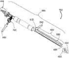
FIGS. 9A-9G illustrate tested tool tip designs according to certain embodiments;
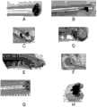
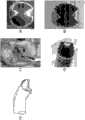
fig. 10A to 10E illustrate a modification (advance) of the cutter head according to some embodiments;
fig. 11A-11C illustrate bayonet-type communication between a cutting head and a suction assembly according to certain embodiments.
Detailed Description
The teachings provided herein are generally directed to a safe and effective cutting head for use in surgical procedures to remove target tissue from a subject. The target tissue may include any tissue that may be accessed through a small surgical opening, such as joint tissue (e.g., meniscus) or intervertebral disc tissue (e.g., nucleus pulposus). In certain embodiments, the device taught herein may be referred to as an orthopedic tissue removal device (orthopedics tissue removal device). In certain embodiments, the devices taught herein are useful in an X-LIF (lateral approach to intervertebral fusion) procedure, a T-LIF (transforaminal to intervertebral fusion) procedure, a P-LIF (posterior approach to intervertebral fusion) procedure, or a percutaneous intervertebral access (a percutaneous, transforaminal approach).
In certain embodiments, the terms "target" and "patient" are used interchangeably, and "target" and "patient" refer to an animal, e.g., a mammal, including, but not limited to, a non-primate (such as a cow, pig, horse, cat, dog, murine) and a primate (such as a monkey or human). Thus, the terms "target" and "patient" may also apply to non-human biological contexts, including but not limited to disease animals, pets, commercial livestock, and the like.
The cutting head may be tubular with a cutting surface forming at least a first face on a distal periphery of the cutting head, the cutting head being in operable communication with a suction device to resect target tissue in a manner to facilitate removal of the tissue by suction.
The cutting surface may be, for example, flat, sinusoidal, or serrated, and the first face of the cutting surface may form an angle θFPThe angle thetaFPUp to 75 from a position orthogonal to a central axis of the tool bit. In some embodiments of the present invention, the substrate is,the cutting surface may have a second face, which may form an angle θSPThe angle thetaSPUp to 75 from a position orthogonal to a central axis of the tool bit. In some embodiments, the cutting head has a cutting edge and a cutting edge guard for preventing peripheral tissue from being cut by the cutting edge. In certain embodiments, the angle θFPAnd angle thetaSPMay be independently selected from the range of 0 ° to about 75 °, about 5 ° to about 75 °, about 10 ° to about 70 °, about 15 ° to about 65 °, about 10 ° to about 60 °, about 5 ° to about 55 °, about 15 ° to about 50 °, about 20 ° to about 45 °, about 15 ° to about 40 °, about 25 ° to about 35 °, or may be independently selected from any angle or any angular range herein increased by 1 °.
Fig. 1A-1D illustrate various tubular bit configurations that may be made from tubing (stock tube), according to some embodiments. FIG. 1A shows abit tube 100 having afirst face 105, thefirst face 105 forming an angle θFPThefirst face 105 is orthogonal to thecentral axis 110 of the lumen of thetubing 100. FIG. 1B shows abit tube 100 having afirst face 105, thefirst face 105 forming an acute angle θ with acentral axis 110 of the lumen of thetube 100FPThe acute angle thetaFPIn the range of 1 deg. to about 75 deg.. FIG. 1C illustrates atool bit tube 100 having afirst face 105, thefirst face 105 forming an acute angle θ with acentral axis 110 of the lumen of thetube 100FPThe acute angle thetaFPIn the range of 1 ° to about 75 °; and the bit tube has asecond face 105, thesecond face 105 forming an angle thetaSPThesecond face 105 is orthogonal to the central axis of theinner cavity 110 of thetubing 100. FIG. 1D illustrates abit tube 100, thebit tube 100 having afirst face 105, thefirst face 105 forming an acute angle θ with a central axis of theinner cavity 110 of thetube 100FPThe acute angle thetaFPIn the range of 1 ° to about 75 °; and the cutting head tube has asecond face 105, thesecond face 105 forming an acute angle θ with acentral axis 110 of the lumen of thetube 100SPThe acute angle thetaSPIn the range of 1 to about 75And (4) the following steps.
The cutting head may be fabricated from any material known to those skilled in the art to be suitable for the surgical environment in which the teachings herein are used. For example, hard materials having a hardness greater than Rockwell C30 or a hardness greater than Rockwell C45 may be suitable in certain embodiments. In some embodiments, the cutting head may comprise a composition selected from the group consisting of: tempered steel, stainless steel, high carbon steel, titanium or titanium alloys, ceramics, diamond and obsidian. In certain embodiments, the stainless steel may comprise 304 stainless steel, 316 stainless steel, 17-4PH stainless steel, 400 series stainless steel, or any stainless steel material known to those skilled in the art suitable for the cutting function taught herein. In some embodiments, the cutting tip may be made of cobalt chromite (cobalt chromium), tungsten carbide (tungsten carbide), or a ceramic material.
The wall thickness of the tube forming the tool tip may be, for example, between 0.003 "and 0.020", more specifically between 0.005 "and 0.012". The cross-sectional area of the tool tip may be in the range of 0.120 square inches to 1.5 square inches, or, in some embodiments, the cross-sectional area of the tool tip may be in the range of 0.180 square inches to 0.400 square inches. The width in any direction may range from 0.080 "to 0.400" or greater, and in certain embodiments, may range from 0.160 "to 0.250". In some embodiments, the maximum cross-sectional dimension of the tool tip is between 3.0mm and about 20.0mm, between 4.0mm and about 15mm, between about 4.0mm and about 12.0mm, between about 5.0mm and about 10.0mm, between about 5.0mm and about 8.0mm, or any range therein increased by 0.1 mm. In some embodiments, the diameter of the cutting head is about 4.8mm, about 5.0mm, about 5.2mm, about 5.4mm, about 5.8mm, about 6.0mm, about 6.2mm, about 6.4mm, about 6.6mm, about 6.8mm, about 7.0mm, about 7.2mm, about 7.4mm, about 7.6mm, about 7.8mm, about 8.0mm, about 8.2mm, and any diameter 0.1mm added thereto.
The distal perimeter of the cutting tip may be on the first face or the second face, or a combination thereof, and the cutting surface may be any cutting surface known to those skilled in the art, for example, in some embodiments, the cutting surface may be a razor surface, a serrated surface, or a sinusoidal surface. There are many cutting edge designs known to those skilled in the art, and any of these configurations may be utilized. For example, the cutting surface may have teeth and gullets between the teeth. The spacing between the plurality of teeth may be equal or may vary, and the depth of the gullets may be equal or may vary, and any combination of teeth and gullets may be utilized. In some embodiments, the direction of the projection of the tooth may be offset from the direction of the remainder of the wall (remainder) of the cutter head. In some embodiments, the teeth are in the same direction as the remainder of the wall of the cutter head, such that the teeth are simply extensions of the wall of the cutter head and do not change direction toward or away from the internal cavity of the cutter head. In some embodiments, there is a pattern of alternating directions of the teeth away from or toward the interior cavity of the cutter head. For example, the pattern may be in the order of facing, away, no offset, and this order repeats around the distal edge of the outer periphery of the cutting head. In some embodiments, all of the teeth are directed toward the lumen, and in some embodiments, all of the teeth are directed away from the lumen. In some embodiments, each tooth of the plurality of teeth is alternately directed toward and away from the lumen. Also, in certain embodiments, each of the plurality of teeth tapers toward and away from the lumen at progressively increasing and decreasing angles to create a wavy appearance as the teeth encircle the distal edge of the outer periphery. The order may also be completely random.
Fig. 2A-2E illustrate cutting edge configurations according to some embodiments. Fig. 2A shows a 5-tooth shift pattern with repeated facing, away, and no change. Fig. 2B shows a random transformation pattern. Fig. 2C shows a wave-shaped transformation pattern. Fig. 3D shows a 3-tooth shift pattern that repeats away, toward, and no change. Also, FIG. 3E shows a simple repeated far and far, direction transition pattern.
In some embodiments, the configuration of the cutting edge may be selected in conjunction with selecting the profile of the cutting edge. Those skilled in the art of designing cutting edges will appreciate that the tool tips taught herein may have a variety of cutting actions, such as, for example, a chisel action, a sawing action, a slicing action, and a cleaving action. Thus, the profile of the cutting edge selected may be modified to use any cutting edge profile known to those skilled in the art. In certain embodiments, the teeth are beveled. In some embodiments, the cutting head may have a rearward facing tooth and a forward facing tooth to include a forward facing cutting surface in addition to a rearward facing cutting "spur".
Thus, the teachings include a tubular cutting head for removing a target tissue on a subject. Also, the tube may be an elongated, tubular structure having any shape (e.g., round, square, rectangular, elliptical, pentagonal, hexagonal, heptagonal, octagonal, etc.), such that in some embodiments, any number of sides, curves, or a combination thereof of tubes may be utilized. In certain embodiments, a round tube is utilized.
The cutting head may have a combination of various types of cutting edges (e.g., forward, rearward, and lateral cutting edges, as well as projections, hooks, etc.) to grasp, cleave, or otherwise remove tissue. In some embodiments, the cutting head has: a rearward cutting edge for cutting the target tissue in a backward stroke of the cutter head; a transverse cutting edge for cutting the target tissue in a transverse stroke of the cutting head; or a combination of a backward cutting edge and a transverse cutting edge. In some embodiments, a transverse cutting blade may be located on the blade guard for cutting the target tissue during a transverse stroke of the cutting head.
Fig. 3A-3C illustrate cross-sections of individual cutting edge profiles according to some embodiments. Figure 3A shows a planar-concave cutting edge profile. Figure 3B shows a wedge-shaped cutting edge profile. Also, fig. 3C illustrates a chisel cutting edge profile. Likewise, it should be understood that the cutting edge may be designed with any configuration (including single sided, double sided, single barb, double barb, straight tip, barbed tip, etc.) to aid in any form of tissue removal (including cutting, slicing, chiseling, scraping, planing, sawing, grinding, and cleaving of tissue) to effectively remove the tissue, for example, during a surgical procedure.
Fig. 4A-4C illustrate a tool tip according to some embodiments. Fig. 4A shows an oblique view of the cutter head, and fig. 4B shows a side view of the cutter head. Thetool bit 400 may have anouter periphery 405, theouter periphery 405 defining aninternal cavity 410 through thetool bit 400, theinternal cavity 410 having acentral axis 415. The cuttinghead 400 may also have aforward cutting edge 420, theforward cutting edge 420 being located on adistal edge 425 of theouter periphery 405, theforward cutting edge 420 being configured to (i) cut a target tissue (not shown) during the forward stroke of the cuttinghead 400 and (ii) direct the cut target tissue into thelumen 410. Also, the cuttinghead 400 may have acutting blade guard 430 located distal of theforward cutting blade 420 and configured to prevent peripheral tissue (not shown) from being cut by thecutting blade 420 during the forward stroke, thecutting blade guard 430 having awidth 433 less than awidth 422 of the cross-section of theinner lumen 410 to facilitate entry of the target tissue into theinner lumen 410 during the forward stroke. Also, as shown in fig. 4A-4C, the side surfaces 409 of the blade guard may be serrated, or otherwise shaped sharp cutting surfaces for transverse cutting.
Since the cutting-head can be designed to remove tissue by usingsuction 444, the teachings also refer to a system of cutting-heads that operatively connects the cutting-head to a suction assembly 484 (only the distal end is shown). Thus, fig. 4C also illustrates a surgical tissue removal system that includes a tubular cutting-head 400, the cutting-head 400 being used to remove a target tissue of interest (not shown). The surgical tissue removal system can include a cuttinghead 400, the cuttinghead 400 having: an outer periphery defining asuction flow 444 through thecutter head 400; alumen 410, thelumen 410 being defined by theouter periphery 405, thelumen 410 directing asuction flow 444 and having acentral axis 415; aforward cutting edge 420, theforward cutting edge 420 being on adistal edge 425 of theouter periphery 405, theforward cutting edge 420 being configured to (i) cut the target tissue during the forward stroke of the cuttinghead 400 and (ii) direct the cut target tissue into thelumen 410; and ablade guard 430, theblade guard 430 being located distally relative to theforward cutting blade 420 and configured to prevent peripheral tissue (not shown) from being cut by theforward cutting blade 420 during the forward stroke.
The cutting head can be configured to operably communicate between thelumen 410 and thesuction source 444, and thus, thesystem 400 includes asuction assembly 484, thesuction assembly 484 operably communicating with the cuttinghead 400 to generate a flow ofsuction 444 to remove the target tissue out of the target through thelumen 410, thesuction assembly 484 including arigid suction tube 488, thesuction tube 488 having a central axis. In some embodiments, the operative communication includes the use of one ormore suction ports 466, thesuction port 466 being located at a proximal-most point proximate a distal-most edge of the bit periphery. In some embodiments, the one ormore suction ports 466 can be located approximately 3mm to 20mm proximal to the closest point of thedistal edge 425. Without being bound by any theory or mechanism of action, those skilled in the art will appreciate that an additional source of air may be useful when suctioning within an area where a vacuum may be created that may otherwise impede or terminate the suction flow that transports excised tissue away from the surgical field during removal of tissue. Thesuction port 466 may be used to provide additional air to avoid creating a vacuum in the surgical field.
Any pumping assembly configuration known to those skilled in the art may be utilized in many embodiments. In certain embodiments,suction assembly 484 includes an at least substantiallyrigid suction tube 488,suction tube 488 having a proximal end (not shown) and adistal end 499,distal end 499 being operably in communication with cutting-head 400, anddistal end 499 being configured to communicate withsuction source 444 forsuction assembly 484. In some embodiments, an at least substantiallyrigid suction tube 488 can be formed integrally with cutting-head 400. The phrase "at least substantially rigid" may refer to an element that is rigid, or sufficiently rigid, such that a desired function is achieved under the forces generated by normal use. For example, the desired function may be to prevent or prevent the rigid element from creating a bending moment at one or more points along the length of the rigid suction tube when the cutting head is used on the target.
The following table describes the dimensional ratios of the cuttinghead 400 that have been found to achieve rapid and effective tissue removal in a discectomy. "labels" are used to show the elements and measures that form the dimensional ratios described on small and large devices.

The rigid suction tube may comprise any material known to those skilled in the art to be suitable for use in the teachings herein. For example, the rigid suction tube may comprise any surgical steel, plastic or resin deemed necessary by those skilled in the art for the devices taught herein. In some embodiments, the rigid suction tube may comprise the same or similar material as the cutting head. In certain embodiments, the rigid suction tube may comprise stainless steel, Polyetheretherketone (PEEK), polyimide, or carbon fiber. The wall thickness of the shaft can be any thickness where the selected material will have the desired physical properties. In certain embodiments, the wall thickness may be, for example, in the range of 0.003 "to 0.020", and, in certain embodiments, may be in the range of 0.005 "to 0.010". The inner lumen surface of the aspiration tube may be coated with polytetrafluoroethylene (TEFLON), a hydrophobic coating (e.g., parylene), or a hydrophilic coating (e.g., polyvinyl alcohol or polyethylene glycol).
In some embodiments, the rigid suction tube may comprise a metal braided wire reinforced polymer tube, coiled tube, or tube with transverse grooves to facilitate articulation in some embodiments where articulation is desired. In these embodiments, the cutting head can be angled relative to the axis of the rigid suction tube by, for example, pulling a tendon (tendon) attached to one side of the cutting head that extends along a guide (guide) on one side of the rigid suction tube.
Fig. 5A and 5B illustrate angles of atool tip 500 according to some embodiments. FIG. 5A illustrates that thecentral axis 515 of thelumen 510 may form an angle θ with thecentral axis 555 of thesuction flow 544 at the distal end 599 of the suction assembly (partially shown) 5841The angle theta1In the range of about 5 to about 90, and theforward cutting edge 520 may be at a distance angle θ1From about 2mm to about 25 mm. In some embodiments, θ1May be in the range of about 2mm to about 30mm, about 2.5mm to about 25mm, about 3mm to about 25mm, about 4mm to about 20mm, about 5mm to about 15mm, about 3mm to about 25mm, about 7mm to about 12mm, about 8mm to about 10mm, or any range there between increased by 0.5 mm.
In certain embodiments, the angle θ between the central axis of the lumen and the central axis of the rigid suction tube1In the range of about 5 ° to about 90 °, and the forward cutting edge distance angle θ1From about 3mm to about 25 mm. Also, in certain embodiments, the central axis of the lumen has an exit point on the forward cutting blade, and the exit point is located at a transverse distance of about 3mm to about 25mm, the transverse distance being orthogonal to the central axis of the rigid suction tube.
In some embodiments, the central axis of the lumen is aligned with the suction portAn angle theta between central axes of the suction flow of the distal end of the suction assembly1In the range of 1 DEG to 180 DEG, and a forward cutting edge distance angle theta13mm to 25 mm. In these embodiments, the additional angle θ3At approach angle theta1At a position of 5mm to 25mm, and an angle theta1And angle theta3Are independently selected from the range of about 0 DEG to about 180 DEG and are limited to (i) the central axis of the cutting head and the approach angle theta3The net angle theta between the central axes of the rigid suction pipes4Between 0 ° and 90 °; and (ii) the distance between the central axis of the lumen of the cutting head and the central axis of the rigid suction tube is between 2mm and 30 mm. Thus, at the angle θ1And angle theta3The distance of the suction flow therebetween may be between about 5mm to about 30mm, between about 5mm to about 25mm, between about 5mm to about 20mm, between about 6mm to about 18mm, between about 7mm to about 15mm, or any range therein increased by 1 mm.
In some embodiments, the operative communication between the cuttinghead 500 and thesuction assembly 584 may be articulated through an angle θ1May be adjustable. In some embodiments, the operative communication between the cuttinghead 500 and thesuction assembly 584 can be rigid, with an angle θ1May be fixed. In certain embodiments, the angle θ1May be in the range of 0 ° to about 45 °, in the range of about 1 ° to about 40 °, in the range of about 5 ° to about 35 °, in the range of 10 ° to about 35 °, in the range of 15 ° to about 40 °, in the range of 20 ° to about 30 °, or any range increased by 1 ° herein. In certain embodiments, the angle θ1May be about 3 °, about 5 °, about 10 °, about 15 °, about 20 °, about 25 °, about 30 °, about 35 °, about 40 °, about 45 °, or any angle herein increased by 1 °.
In some embodiments, the rearward-facing cutting edge can be located on thedistal edge 525 of theouter perimeter 505 to cut the target tissue during the return stroke of the cuttinghead 500. In thatIn some embodiments, a rearward facingcutting blade 531 can be positioned on theblade guard 530 to cut the target tissue during the return stroke of the cuttinghead 500. Fig. 5B illustrates aguard 530 having a dual-edged tip as a rearward-facingcutting edge 531 at an angle θ of greater than 90 ° from thecentral axis 515 of thelumen 5002Is directed rearwardly toward theinternal cavity 515 to grasp and/or cut tissue in theinternal cavity 510 during the return stroke of the cuttinghead 500. Since the function of the rearward-facing cutting edge may be to grasp, shear, and hook tissue to be removed, in certain embodiments, the rearward-facingcutting edge 531 may be referred to as a "claw (talon)" or a "pincer (pincer)".
It should be understood that the cutting heads and systems taught herein have numerous applications known to those skilled in the art. In certain embodiments, for example, the target tissue may be the nucleus pulposus, and the peripheral tissue may be, for example, the annulus fibrosus.
A surgical tissue removal system for a discectomy is provided and may include a tubular cutting head for removing a nucleus pulposus from a target. In these embodiments, the surgical tissue removal system may comprise: a tool bit having: an outer periphery defining a suction flow through the cutter head; a lumen defined by the outer periphery and directing the suction flow; a forward cutting edge on a distal edge of the outer periphery, the forward cutting edge configured to (i) cut the nucleus pulposus during an advancing stroke of the cutting head and (ii) direct the cut nucleus pulposus into the lumen; a backward cutting blade for cutting the nucleus pulposus in a backward stroke of the cutter head; a transverse cutting edge for cutting the nucleus pulposus in a transverse stroke of the cutter head; and a blade guard distal to the forward cutting blade and configured to prevent the forward cutting blade from cutting the annulus fibrosus during the forward stroke.
Another valuable feature is that the device of the teachings described herein can be operated without substantial obstruction to the flow of tissue being resected by the cutting head and by design to achieve this. Without being bound by any theory or mechanism of action, it will be found that the cross-sectional area of the distal end of the cutting head will be at least approximately equal to or less than the cross-sectional area of any point near the distal end of the cutting head that causes (leading to) the flow of tissue that the cutting head resects to converge. These points will include, for example, any point along the cross-section of the rigid suction tube, or any other element of the suction assembly that causes a collection point for the excised tissue, e.g., in some embodiments, a pressure differential that dumps the excised tissue to the nearest orifice in a collection canister (collecting vessel). In certain embodiments, the term "at least approximately equal" means that there may be a smaller cross-sectional area, as long as it is limited to a smaller range. In some embodiments, the cross-sectional area can be at least approximately equal to the cross-sectional area of the cutting head if the cross-sectional area is less than the cross-sectional area of the cross-section at the proximal end by no more than 20%. In some embodiments, the cross-sectional area can be at least approximately equal to the cross-sectional area of the cutting head if the cross-sectional area is less than the cross-sectional area at the proximal end by no more than about 3%, about 5%, about 7%, about 9%, about 11%, about 13%, about 15%, about 17%, about 19%, or about 21%. The amount of smaller cross-sectional area than the proximal cross-section may here be any percentage increase of 1%.
The teachings also include a method of removing a target tissue from a subject. In these embodiments, the method can include fabricating an opening in the subject for access to the target tissue; inserting a cutting head as taught herein through the opening to access a target tissue in the subject; imaging the depth of the tip of the tool tip using a suitable imaging technique (e.g., fluoroscopy); and advancing the cutting head in a forward direction over a surface including the target tissue to remove the target tissue while activating a vacuum to aspirate adjacent excised tissue. The forward direction may include a force vector that moves (i) at least generally on a plane that includes a central axis of the lumen of the cutting head, (ii) at least generally on a surface that includes the target tissue, and (iii) toward the peripheral tissue that is protected by the cutting blade guard. Also, the method can include grasping target tissue within a lumen of the cutting head and passing the target tissue through the lumen and out of the target.
The term "at least approximately at … …" may refer to a position or movement that is sufficiently close to an exact desired position that the desired function may be achieved under the forces and conditions that would normally be generated using the system taught herein. For example, "at least substantially on a plane including the central axis of the lumen of the cutting head" or "at least substantially on a surface including the target tissue" may refer to a position or movement parallel or substantially parallel to the plane or surface, but the position may deviate from the actual plane or surface by about 1um to about 15mm, or the direction of movement may deviate from about 0.1 ° to about 20 °. An "at least approximately" measurement is used in an approximation context where an exact measurement or an exact position cannot be obtained, but one of ordinary skill in the art can obtain the desired functionality. For example, a diminished result, when compared to the best possible result, can be used to determine what is the "at least approximate" desired result. In certain embodiments, the desired result is at least approximately achieved where the best possible result is reduced by less than 10%, less than 15%, less than 20%, less than 30%, less than 40%, or less than 50%. In certain embodiments, the desired result is at least approximately achieved at a location within any range of about 5% to about 30%, about 7% to about 35%, about 10% to about 25%, or an increase of 1% therein, of the reduction in the best possible result.
In a discectomy, the opening in the target may be altered according to the disc height of the target, which is typically in the range of about 5mm to 7 mm. In certain embodiments, the size of the opening in the target may be in the range of about 4mm x 4mm to about 14mm x 14 mm. In some embodiments, the opening may be about 10mm by 7 mm.
In certain embodiments, the method comprises advancing a cutting head taught herein in a rearward direction over a surface comprising the target tissue to remove the target tissue. The rearward direction may include a force vector that moves (i) in a plane that is at least generally in a plane that includes a central axis of the lumen of the cutting head, (ii) in a plane that includes at least generally the target tissue, and (iii) away from the peripheral tissue protected by the cutting blade guard.
In certain embodiments, the method comprises advancing a cutting head as taught herein in a lateral direction over a surface comprising the target tissue to remove the target tissue. For example, the transverse direction may include a force vector that moves (i) at an angle in a range of about 15 ° to about 165 ° from a plane including a central axis of the lumen of the cutting head, (ii) at least substantially over a surface including the target tissue, and (iii) into contact with peripheral tissue protected by the blade guard.
The blades taught herein are sharp and may be harmful to tissue as the blade enters or exits through the surgical opening. In some embodiments, an obturator canula (guard canula) is provided to protect the target when the non-linear elongated surgical cutting device is advanced or withdrawn.
Figure 6 illustrates an obturator protective cannula according to certain embodiments. Theobturator guard cannula 600 may include: aninlet hub 605, theinlet hub 605 having aninner periphery 615, anouter periphery 625, and aflush port 635, theflush port 635 communicating between theinner periphery 615 and theouter periphery 625; and a linear, elongated split-tube 650, the split-tube 650 having aproximal end 655, adistal end 665, and a lumen 675. In these embodiments, theproximal end 655 of the split-tube 650 can (i) define at least a portion of theinner circumference 615 of theinlet hub 605 and (ii) be in operable communication with theirrigation port 635. In these embodiments, the communication is operable to receive theirrigation fluid 690 from theirrigation port 635, and the delivery of theirrigation fluid 690 to the target tissue (not shown) includes, for example, theirrigation fluid 690 moving on theinner lumen surface 680 of the split-tube 650 from theirrigation port 635 to thedistal end 665 of the split-tube 650.
One skilled in the art will appreciate that the "flushing fluid" may be any fluid desired by one skilled in the art, including liquids and gases. In certain embodiments, the flushing fluid may be aqueous (aqueous). In certain embodiments, the flush fluid may be non-aqueous (non-aqueous). Also, in certain embodiments, the irrigation fluid may be an emulsion. In certain embodiments, the flushing fluid may comprise a gas. Examples of aqueous rinse fluids may include water, saline (saline), or aqueous surfactants including liquids (aqueous surfactants). Examples of non-aqueous fluids may include any oil-based liquid that may be helpful in achieving tissue extraction during surgery. Examples of gases may include carbon dioxide, nitrogen, air, and any inert or at least substantially non-reactive gas. In certain embodiments, the flushing fluid may include a lubricant, such as glycerin, silicone oil, and the like. The irrigation fluid may serve as a carrier to aid in the removal of the resected tissue or to prevent the creation of a vacuum at the surgical site that may interfere with the removal of the resected tissue. An example of such a vacuum is that generated when suction is applied within a closed cavity (e.g., an intervertebral space within the annulus) during a discectomy.
Thedistal end 665 of the split-tube 650 can also have any configuration desired by one skilled in the art. For example, thedistal end 665 can be at least generally pointed and/or non-blunt. In some embodiments,distal end 665 can be at least substantially blunt to avoid injuring the entry tissue whendistal end 665 is in contact with the entry tissue. The length of the split-tube 650 can also be in the range of about 10cm to about 60cm, and the width of the split-tube 650 can be in the range of about 5mm to about 16 mm. Further, the slit (split) in the split-tube 650 constitutes agap 667, thegap 667 having a width in the range of about 4mm to about 14mm, the slit having a non-linearity in the surgical device. In some embodiments, the diameter of the cutting head taught herein may be smaller than the diameter of the portion of the suction assembly that passes through the lumen of the obturator guard cannula, such that the obturator guard cannula retains thesuction assembly 484 but allows the cuttinghead 400 to pass through thegap 667. Thus, the width of thegap 667 can exceed the diameter of the cuttinghead 400, but be less than the diameter of therigid suction tube 488, and the diameter of the lumen of the obturatorprotective cannula 600 is greater than the diameter of therigid suction tube 488.
As noted above, the systems taught herein may be used in a variety of surgical procedures for removing target tissue from a subject, including, for example, removal of a meniscus or discectomy. In some embodiments, the surgical resection device used with the protective cannula may be a discectomy device. Also, in some embodiments, the inlet tissue comprises epithelial tissue, muscle tissue, neural tissue, connective tissue, blood vessels, bone, cartilage, or a combination thereof on the target leading to the nucleus pulposus. Thus, in some embodiments, the target tissue may comprise the nucleus pulposus.
A surgical tissue removal tool having a surgical tissue removal system and a closed-cell protection cannula is provided that utilizes any combination of the embodiments of the system and the protection cannula taught herein. In some embodiments, the tool may be a discectomy tool. Thus, in certain embodiments, the inlet tissue comprises epithelial tissue, muscle tissue, neural tissue, connective tissue, blood vessels, bone, cartilage, or a combination thereof on the target leading to the nucleus pulposus. Thus, in some embodiments, the target tissue may comprise the nucleus pulposus.
Fig. 7 illustrates a surgical tissue removal tool according to some embodiments. Thetool 700 includes a cuttinghead 400, asuction assembly 484, and aobturator guard cannula 600.Suction flow 444 from thesuction assembly 484 enters the cuttinghead 400 to remove the target tissue excised by the cutting head.Irrigation water 690 may enter theirrigation valve 795 and/or theirrigation port 635, with theirrigation water 690 from theirrigation valve 795 being utilized when thesuction 444 is closed, and with theirrigation water 690 from theirrigation port 635 being utilized when thesuction 444 is open, during which thesuction 444 directs theirrigation water 690 between the luminal surface of theobturator guard cannula 600 and thesuction assembly 484 into the surgical field (not shown). Theprotective cannula 600 serves to protect the portal tissue (not shown) as the cutting-head 400 andsuction assembly 484 are moved relative thereto during a procedure, such as when the cutting-head 400 is moved forward, backward, and/or laterally to resect and remove a target tissue.
A method of removing a target tissue using the surgical tissue removal tool is provided. In certain embodiments, the method comprises: making an opening in the target for accessing the target tissue; inserting a cutting head of the surgical tissue removal tool through an entry hub and an elongated split-tube of a protective cannula of the surgical tissue removal tool; inserting the cutting tip of the surgical tissue removal tool through the opening to access target tissue in the target while protecting the entry tissue with the blunt distal end of the split-tube. In other aspects, methods of using the tissue removal system are the same as or similar to those taught herein. It will be appreciated by those skilled in the art that the surgical tissue removal tool described above is used, for example, in a discectomy in which the target tissue may be the nucleus pulposus and the surrounding tissue may be the annulus fibrosus. It will also be appreciated by those skilled in the art that the surgical tissue removal tool is provided with a protective cannula that helps protect the target epithelial tissue, muscle tissue, neural tissue, connective tissue, blood vessels, bone, cartilage or combinations thereof that are passed to the nucleus pulposus during such procedures.
Figures 8A-8C illustrate a surgical tissue removal system or tool that can apply suction while irrigating and that does not require an obturator protective cannula to be installed in place, according to some embodiments. Fig. 8A illustrates acomplete discectomy system 800, thediscectomy system 800 including a cuttinghead 400, a tool for providing aspiration flow through anaspiration assembly 884, acontrol handle 886 andvacuum attachment 892, anirrigation tube 804, irrigation controls 802, and optional vacuum controls 888.
In embodiments where the angle of the cutting head is adjustable, handle 886 may have a knob (not shown) that is turned to tension a pull cord (pull cable) to retract or straighten the cutting head relative to the rigid suction tube, or handle 886 may have a slide that tensions the pull cord to retract or straighten the cutting head relative to the rigid suction tube. The pull cords for retraction or straightening may be located on opposite sides of a shaft constrained by small side cavities attached to the outer surface of the shaft to retract and straighten the cutter head.
Fig. 8B illustrates a cross-sectional view of theirrigation tube 804 relative to arigid suction tube 894. Also, fig. 8C shows a cross-sectional view of the control handle 886 and the inner tube.
Those skilled in the art will appreciate that the teachings and examples provided herein refer to a basic concept that may be extended beyond any specific embodiment or embodiments, or one or more of the accompanying drawings. It should be understood that any of the examples are for illustrative purposes and are not to be construed as limiting other aspects of the teachings.
Example 1 test tool tip design
Multiple heads were tested on 28 discs from 3 cadaver experiments (cadover laboratories). The results are compared to determine the most efficient bit design. The ideal cutting head is designed to cut all of the targeted tissue including the nucleus pulposus, vertebral end plates (verterbral endplates) and the inner annulus tissue well. However, the cutting head should also cut the target tissue in a desired manner without providing damage to the surrounding tissue, including the surrounding annulus fibrosus, which should be preserved as a desired surrounding structure. Furthermore, the blade design should remove tissue quickly under suction, and therefore the blade configuration enables the tissue removal under suction.
Fig. 9A-9G illustrate tested tool tip designs according to some embodiments. The bit design in fig. 9A cuts well, but is less safe for the annulus than other bit designs. The bit design in fig. 9B is safe for the annulus, but does not cut tough tissue well and exhibits too much resistance. The design in fig. 9C also did not penetrate tough tissue well. The design in fig. 9D does cut and exfoliate well, but the design is clogged on soft/elastic tissue. The design in fig. 9E cuts tough tissue very well without clogging, and the design peels very well. The design is also safe for the ring. However, the device is not shaped to reach the distal side of the nucleus pulposus. The design in fig. 9F shows the bend (a bend) of the introduced device that enables the blade of fig. 9E to reach the distal side of the nucleus pulposus. However, the design in fig. 9G and 9H demonstrates the most effective insert performance verified in the test, with the design in fig. 9G and 9H removing 23cc of material in 5 minutes.
Example 2
This embodiment further expands the design of the cutter head. The designs in fig. 8G and 8H were further studied in 7 cadaver experiments and 28 discs.
Fig. 10A-10E illustrate improvements in the cutter head according to certain embodiments. The design in fig. 10A shows a head with a bevel angle on the outer surface of the cutting tooth and a device that cuts poorly and requires cutting (gouge) cartilage. The design in fig. 10B shows an oval shaped cutting head with no bevel angle on the outer surface of the cutting teeth and a device that produces inconsistent cuts and requires cutting of cartilage. The design in fig. 10C shows the comparison results with the use of a ring curette and the device used to cut cartilage. The design in fig. 10D shows a short bit with one "claw" or clamp and a device that shows the most attractive results and achieves the best cut without the need for excavation. Fig. 10E is another preferred design configured to function as the design of fig. 10D, with the design of fig. 10E also having a second jaw that curves away from the internal cavity of the bit to act as an additional jaw and cutting edge guard.
The method used in this example is as follows:
1. cutting guide holes with the height and width dimensions of 5mm to 8 mm;
2. a 15 deg. tip parallel to the vertebral endplates is pointed to cut and expand the cavity centrally and laterally.
3. Gradually shaving the vertebral endplates to hard tissue (cartilage or bone); confirming the depth of the tip by fluoroscopy; shaving along the curve of the vertebral endplate with the tip; stopping shaving when bone (hard, rough, sticky and red aspirate identified as the end point) is exposed; and the handle of the device is tilted (i) centrally to strip the side edges and (ii) laterally to strip the medial side.
4. Pushing the blade medially-laterally against the anterior annulus as needed to remove the nucleus attached to the annulus and inner annulus;
5. directing the 40 ° tip to the opposite side and starting to shave from the posterior annulus while tilting the handle laterally to remove most of the nucleus pulposus; and
6. the handle is rotated toward the vertebral endplate for further ablation.
Example 3
This example describes an alternative embodiment for testing, referred to as a bent or bayonet structure (serpentine or)bayonet configuration), wherein therigid suction tube 488 may have at least two angles: angle theta1And angle theta3。
Fig. 11A-11C illustrate bayonet-type communication between a cutting head and a suction assembly according to some embodiments. It has been found that the distal end of therigid suction tube 488 can be redirected in a bayonet or curved manner to bring the cutting head closer to the target tissue in, for example, a discectomy. As shown in fig. 11A to 11C, the angle θ1And angle theta3May each be independently selected from the range of about 0 to about 180 and limited to (i) the central axis of thelumen 410 of the cuttinghead 400 and (ii) thecentral axis 497 of the rigid suction tube 488 (extending toward the approach angle θ)1) Net angle θ realized therebetween4The net angle theta4In the range of 0 ° to 90 °; and (ii) thedistance 498 between thecentral axis 415 of thelumen 410 of the cuttinghead 400 and thecentral axis 497 of therigid suction tube 488 can be in the range of about 2mm to about 30 mm. Also, in these embodiments, the central axis of the lumen may have an exit point at the forward cutting edge and the exit point is located at a lateral distance of about 3mm to about 25 mm.
In certain embodiments, thedistance 498 is between about 2.5mm to about 25mm, between about 3mm to about 25mm, between about 4mm to about 20mm, between about 5mm to about 15mm, between about 3mm to about 25mm, between about 7mm to about 12mm, between about 8mm to about 10mm, or any range there between increased by 0.5 mm. Accordingly, thedistance 498 may be approximately 2mm, approximately 3mm, approximately 4mm, approximately 5mm, approximately 6mm, approximately 7mm, approximately 8mm, approximately 9mm, approximately 10mm, approximately 12mm, approximately 14mm, approximately 16mm, approximately 18mm, approximately 20mm, approximately 22mm, approximately 24mm, approximately 26mm, approximately 28mm, approximately 30mm, and any distance or range there between that is increased by 0.5 mm. In certain embodiments, the angle θ3May be between about 5mm and about 25mm, between about 6mm and about 20mm, between about 7mm and about 15mm, or any range therein increased by 1 mm.
Claims (44)
1. A tubular cutting head for removing a target tissue of a subject, the cutting head having:
an outer periphery defining an inner cavity through the cutter head, the inner cavity having a central axis;
a forward cutting edge at a distal edge of the outer periphery, the forward cutting edge configured to (i) cut a target tissue during an advancing stroke of the cutting head and (ii) direct the cut tissue to the lumen; and
a blade guard distal to the forward cutting blade and configured to prevent the forward cutting blade from cutting peripheral tissue during the forward stroke, the blade guard having a width less than a width of a cross-section of the internal cavity to facilitate entry of the target tissue into the internal cavity during the forward stroke.
2. The cutting head of claim 1, further comprising a rearward cutting edge for cutting the target tissue during a return stroke of the cutting head.
3. The cutting head of claim 1, further comprising a transverse cutting edge for cutting the target tissue during a transverse stroke of the cutting head.
4. The cutting head of claim 1, further comprising a transverse cutting blade on the blade guard for cutting the target tissue during a transverse stroke of the cutting head.
5. A surgical tissue removal system, comprising:
a tubular cutting head for removing a target tissue of interest, the cutting head having:
an outer periphery defining a suction flow through the cutter head;
a lumen defined by the outer periphery, the lumen directing the suction flow and having a central axis;
a forward cutting edge at a distal edge of the outer periphery, the forward cutting edge configured to (i) cut the target tissue during an advancing stroke of the cutting head and (ii) direct the cut target tissue to the lumen; and
a blade guard distal to the forward cutting blade and configured to prevent the forward cutting blade from cutting peripheral tissue during the forward stroke, the blade guard having a width less than a width of a cross-section of the internal cavity to facilitate entry of the target tissue into the internal cavity during the forward stroke;
wherein the cutting head is configured to operably communicate between the lumen and a suction source;
and,
a suction assembly in operable communication with the cutting head, the suction assembly including an at least substantially rigid suction tube having a central axis, and the suction assembly creating a suction flow for passing the target tissue through the lumen and out of the target.
6. The surgical tissue removal system of claim 6, wherein the at least substantially rigid suction tube is formed as one piece with the cutting head.
7. The system of claim 5, wherein the cutting head further has a rearward-facing cutting edge for cutting the target tissue in a return stroke of the cutting head.
8. The system of claim 5, wherein the cutting head further has a transverse cutting edge for cutting the target tissue in a transverse stroke of the cutting head.
9. The surgical tissue removal system of claim 5, wherein a central axis of the lumen forms an angle θ with a central axis of the rigid suction tube1The angle theta1In the range of about 5 ° to about 90 ° and the forward cutting edge is located at a distance θ from the angle1From about 3mm to about 25 mm.
10. The surgical tissue removal system of claim 9, wherein the operative communication between the cutting head and the suction assembly is articulated and the angle θ1Is adjustable.
11. The surgical tissue removal system of claim 9, wherein the operative communication between the cutting head and the suction assembly is rigid, and the angle θ1Is stationary.
12. The surgical tissue removal system of claim 9, wherein the central axis of the lumen has an exit point at the forward cutting blade and the exit point is located at a transverse distance of about 3mm to about 25mm that is orthogonal to the central axis of the rigid suction tube.
13. The surgical tissue removal system of claim 5, wherein a central axis of the lumen forms an angle θ with a central axis of the rigid suction tube1The angle theta1In the range of 1 ° to 180 ° and the forward cutting edge is located at a distance θ from the angle13mm to 25mm of apex; wherein,
additional angle theta3The additional angle theta3At approach angle theta15mm to 25 mm;
angle theta1And angle theta3Independently of each other, selected from the range of about 0 DEG to about 180 DEG, angle theta1And angle theta3The limitation is:
(i) the central axis and the approach angle theta of the inner cavity of the cutter head3Has a net angle theta between the central axes of said rigid suction pipes4The net angle theta4In the range of 0 ° to 90 °; and
(ii) the central axis of the lumen has an exit point at the forward cutting blade and the exit point is at a transverse distance of about 3mm to about 25mm, the transverse distance being orthogonal to the central axis of the rigid suction tube.
14. The surgical tissue removal system of claim 5, wherein the target tissue is a nucleus pulposus and the peripheral tissue is an annulus fibrosus.
15. A surgical tissue removal system for a discectomy, the surgical tissue removal system comprising:
a tubular cutting head for removing a nucleus from a subject, the cutting head having:
an outer periphery defining a suction flow through the cutter head;
an inner lumen defined by the outer periphery, the inner lumen directing the suction flow;
a forward cutting edge located at a distal edge of the outer periphery, the forward cutting edge configured to (i) cut the nucleus pulposus during an advancing stroke of the cutting head and (ii) direct the cut nucleus pulposus into the lumen;
a backward cutting blade for cutting the nucleus pulposus in a backward stroke of the cutter head;
a transverse cutting edge for cutting the nucleus pulposus in a transverse stroke of the cutter head; and
a blade guard distal to the forward cutting blade and configured to prevent the forward cutting blade from cutting the annulus fibrosus during the forward stroke, the blade guard having a width less than a width of a cross-section of the inner lumen to facilitate entry of the target tissue into the inner lumen during the forward stroke;
wherein the cutting head is configured to operably communicate between the lumen and a suction source;
and,
a suction assembly in operable communication with the cutting head, the suction assembly including an at least substantially rigid suction tube having a central axis, and the suction assembly creating a suction flow for passing the nucleus pulposus through the lumen and out of the target.
16. The surgical tissue removal system of claim 15, wherein the at least substantially rigid suction tube is formed as one piece with the cutting head.
17. The surgical tissue removal system of claim 15, wherein a central axis of the lumen forms an angle θ with a central axis of the rigid suction tube1The angle theta1In the range of about 5 ° to about 90 ° and the forward cutting edge is located at a distance θ from the angle1From about 3mm to about 25 mm.
18. The surgical tissue removal system of claim 15, wherein the central axis of the lumen has an exit point at the forward cutting blade and the exit point is located at a transverse distance of about 3mm to about 25mm that is orthogonal to the central axis of the rigid suction tube.
19. The surgical tissue removal system of claim 17, wherein the operative communication between the cutting head and the suction assembly is articulated and the angle θ1Is adjustable.
20. The surgical tissue removal system of claim 17, wherein the operative communication between the cutting head and the suction assembly is rigid, and the angle θ1Is stationary.
21. The surgical tissue removal system of claim 15, wherein a central axis of the lumen forms an angle θ with a central axis of the rigid suction tube1The angle theta1In the range of 1 ° to 180 ° and the forward cutting edge is located at a distance θ from the angle13mm to 25mm of apex; wherein,
additional angle theta3The additional angle theta3At approach angle theta15mm to 25 mm;
angle theta1And angle theta3Independently of each other, selected from the range of about 0 DEG to about 180 DEG, angle theta1And angle theta3Is limited to
(i) The central axis and the approach angle theta of the inner cavity of the cutter head3Has a net angle theta between the central axes of said rigid suction pipes4The net angle theta4In the range of 0 ° to 90 °; and
(ii) the central axis of the lumen has an exit point at the forward cutting blade and the exit point is at a transverse distance of about 3mm to about 25mm, the transverse distance being orthogonal to the central axis of the rigid suction tube.
22. The system of claim 15, wherein the backward cutting edge is located on a distal edge of the outer periphery for cutting the target tissue in a return stroke of the cutting head.
23. The system of claim 15, wherein the rearward facing cutting blade is located on the blade guard for cutting the target tissue in the return stroke of the cutting head, the blade guard having a dual blade tip at an angle θ greater than 90 °2Is directed rearwardly into the lumen to grasp and/or cut tissue in the lumen during the return stroke of the cutting head.
24. The system of claim 15, wherein the transverse cutting blade is located on the blade guard for cutting the target tissue in a transverse stroke of the cutting head.
25. A method of removing a target tissue from a subject, the method comprising:
creating an opening in the target for access to the target tissue;
inserting the cutting head of claim 5 through the opening to access the target tissue in the subject;
advancing the cutting head in a forward direction on a surface comprising the target tissue to remove the target tissue, the forward direction may comprise a force vector that moves (i) at least substantially on a plane comprising a central axis of the lumen of the cutting head, (ii) at least substantially on the surface comprising the target tissue, and (iii) toward peripheral tissue protected by the cutting blade guard;
grasping the target tissue within the lumen of the cutting head; and
moving the target tissue through the lumen and out of the target.
26. The method of claim 25, further comprising advancing the cutting head in a rearward direction over a surface comprising the target tissue to remove the target tissue, the rearward direction comprising a force vector that moves (i) at least substantially over a plane comprising a central axis of the lumen of the cutting head, (ii) at least substantially over the surface comprising the target tissue, and (iii) away from the peripheral tissue protected by the cutting blade guard.
27. The method of claim 25, further comprising advancing the cutting head in a transverse direction on a surface comprising the target tissue to remove the target tissue, the transverse direction comprising a force vector that (i) moves at an angle in a range of about 15 ° to about 150 ° from a plane comprising a central axis of the lumen of the cutting head, (ii) moves at least substantially on a surface comprising the target tissue, and (iii) moves into contact with the peripheral tissue protected by the cutting blade guard.
28. The method of claim 25, wherein the target tissue is a nucleus pulposus and the peripheral tissue is an annulus fibrosus.
29. An obturator guard cannula for protecting a target during entry and exit of an elongated surgical cutting device, the elongated surgical cutting device having a degree of non-linearity, the guard cannula comprising:
an inlet hub having an inner periphery, an outer periphery, and a flush port communicating between the inner and outer peripheries; and,
a linear, elongated, split-tube having a proximal end, a distal end, and an inner lumen,
wherein,
the proximal end of the split-tube (i) defines at least a portion of the inner periphery of the inlet hub, and (ii) is in operable communication with the irrigation port to operably receive irrigation fluid from the irrigation port, the delivering the irrigation fluid to a target tissue comprising: moving the irrigation fluid from the irrigation port to the distal end of the split-tube over a luminal surface of the split-tube;
the distal ends of the split-tubes are at least substantially blunt to avoid damaging the entry tissue when the distal ends are in contact with the entry tissue;
the split-tube has a length in the range of about 10cm to about 60cm and a width in the range of about 5mm to about 16 mm; and is
The split-tube slit constitutes a gap having a width in the range of about 4mm to about 14mm, the slit having a non-linearity in the surgical device.
30. The obturator protective cannula according to claim 29, wherein,
the surgical cutting device is a discectomy device;
the inlet tissue comprises epithelial tissue, muscle tissue, neural tissue, connective tissue, blood vessels, bone, cartilage, or a combination thereof, to the target of the nucleus pulposus; and
the target tissue includes the nucleus pulposus.
31. A surgical tissue removal tool, comprising:
a surgical tissue removal system, the surgical tissue removal system having:
a tubular cutting head for removing a target tissue of interest, the cutting head having:
an outer periphery defining a suction flow through the cutter head;
a lumen defined by the outer periphery, the lumen directing the suction flow and having a central axis;
a forward cutting edge at a distal edge of the outer periphery, the forward cutting edge configured to (i) cut the target tissue during an advancing stroke of the cutting head and (ii) direct the cut target tissue to the lumen; and
a blade guard distal to the forward cutting blade and configured to prevent the forward cutting blade from cutting peripheral tissue during the forward stroke, the blade guard having a width less than a width of a cross-section of the internal cavity to facilitate entry of the target tissue into the internal cavity during the forward stroke;
wherein,
the cutting head is configured to operably communicate between the lumen and a suction source; and,
a suction assembly in operable communication with the cutting head, the suction assembly including an at least substantially rigid suction tube having a central axis, and the suction assembly creating a suction flow for moving the target tissue through the lumen and out of the target;
and
an obturator guard cannula to protect a target as the surgical tissue removal system enters and exits, the guard cannula comprising:
an inlet hub having an inner periphery, an outer periphery, and a flush port communicating between the inner and outer peripheries; and,
a linear, elongated, split-tube having a proximal end, a distal end, and an inner lumen,
wherein,
the proximal ends of the split-tube
Defining at least a portion of the inner perimeter of the inlet hub; and is
Operably communicating with the irrigation port to operably receive irrigation fluid from the irrigation port, the delivering the irrigation fluid to a target tissue comprising: moving the irrigation fluid from the irrigation port to the distal end of the split-tube over a luminal surface of the split-tube;
the distal ends of the split-tubes are at least substantially blunt to avoid damaging the entry tissue when the distal ends are in contact with the entry tissue;
the split-tube has a length in the range of about 10cm to about 60cm and a width in the range of about 5mm to about 16 mm; and,
the split-tube slit constitutes a gap having a width in the range of about 4mm to about 14mm, the slit having a non-linearity in the surgical device.
32. The surgical tissue removal tool of claim 31, wherein the at least substantially rigid suction tube is formed integrally with the cutting head.
33. The surgical tissue removal tool of claim 31, wherein a central axis of the lumen forms an angle θ with a central axis of the rigid suction tube1The angle theta1In the range of about 5 ° to about 90 °, and said forward facingThe cutting edge being located at a distance theta from said angle1From about 3mm to about 25 mm.
34. The surgical tissue removal tool of claim 31, wherein the central axis of the lumen has an exit point at the forward cutting blade and the exit point is located at a transverse distance of about 3mm to about 25mm that is orthogonal to the central axis of the rigid suction tube.
35. The surgical tissue removal tool of claim 33, wherein the operative communication between the cutting head and the suction assembly is articulated, the angle θ1Is adjustable.
36. The surgical tissue removal tool of claim 33, wherein the operative communication between the cutting head and the suction assembly is rigid, the angle θ1Is stationary.
37. The surgical tissue removal tool of claim 31, wherein a central axis of the lumen and a central axis of the rigid suction tube form an angle Θ therebetween1The angle theta1In the range of 1 ° to 180 ° and the forward cutting edge is located at a distance θ from the angle13mm to 25mm of apex; wherein,
additional angle theta3The additional angle theta3At approach angle theta15mm to 25 mm;
angle theta1And angle theta3Independently of each other, selected from the range of about 0 DEG to about 180 DEG, angle theta1And angle theta3Is limited to
(i) The central axis and the approach angle theta of the inner cavity of the cutter head3Has a net angle theta between the central axes of said rigid suction pipes4The net angle theta4In the range of 0 ° to 90 °; and
(ii) the central axis of the lumen has an exit point at the forward cutting blade and the exit point is at a transverse distance of about 3mm to about 25mm, the transverse distance being orthogonal to the central axis of the rigid suction tube.
38. The surgical tissue removal tool of claim 31, wherein the cutting head further has a rearward-facing cutting edge for cutting the target tissue in a return stroke of the cutting head.
39. The surgical tissue removal tool of claim 31, wherein the cutting head further has a transverse cutting edge for cutting the target tissue in a transverse stroke of the cutting head.
40. The tool of claim 31, wherein,
the target tissue is nucleus pulposus;
the peripheral tissue is an annulus fibrosus; and is
The inlet tissue comprises epithelial tissue, muscle tissue, nerve tissue, connective tissue, blood vessels, bone, cartilage, or a combination thereof, to the target of the nucleus pulposus.
41. A method of removing a target tissue from a subject, the method comprising:
creating an opening in the target for access to the target tissue;
inserting the cutting head of claim 31 through the inlet hub and the elongated split-tube of the protective cannula of claim 31;
inserting the cutting head through the opening to access the target tissue in the subject while protecting the entry tissue with the blunt distal end of the split-tube;
advancing the cutting head in a forward direction on a surface comprising the target tissue to remove the target tissue, the forward direction comprising a force vector that (i) moves at least substantially on a plane comprising a central axis of the lumen of the cutting head, (ii) moves at least substantially on the surface comprising the target tissue, and (iii) moves toward peripheral tissue protected by the cutting blade guard;
grasping the target tissue in the lumen of the cutting head; and,
moving the target tissue through the lumen and out of the target.
42. The method of claim 41, further comprising: advancing the cutting head in a rearward direction on a surface comprising the target tissue to remove the target tissue, the rearward direction comprising a force vector that (i) moves at least substantially on a plane comprising a central axis of the lumen of the cutting head, (ii) moves at least substantially on the surface comprising the target tissue, and (iii) moves away from peripheral tissue protected by the cutting blade guard.
43. The method of claim 41, further comprising advancing the cutting head in a transverse direction on a surface comprising the target tissue to remove the target tissue, the transverse direction comprising a force vector that (i) moves at an angle in a range of about 15 ° to about 150 ° from a plane comprising a central axis of the lumen of the cutting head, (ii) moves at least substantially on a surface comprising the target tissue, and (iii) moves into contact with the peripheral tissue protected by the cutting blade guard.
44. The method of claim 41, wherein
The target tissue is nucleus pulposus;
the peripheral tissue is an annulus fibrosus; and,
the inlet tissue comprises epithelial tissue, muscle tissue, nerve tissue, connective tissue, blood vessels, bone, cartilage, or a combination thereof, to the target of the nucleus pulposus.
Applications Claiming Priority (5)
| Application Number | Priority Date | Filing Date | Title |
|---|---|---|---|
| US201161566629P | 2011-12-03 | 2011-12-03 | |
| US61/566,629 | 2011-12-03 | ||
| US201261596865P | 2012-02-09 | 2012-02-09 | |
| US61/596,865 | 2012-02-09 | ||
| PCT/US2012/051952WO2013081691A1 (en) | 2011-12-03 | 2012-08-22 | Safe cutting heads and systems for fast removal of a target tissue |
Publications (2)
| Publication Number | Publication Date |
|---|---|
| CN103327913Atrue CN103327913A (en) | 2013-09-25 |
| CN103327913B CN103327913B (en) | 2015-09-09 |
Family
ID=48524529
Family Applications (1)
| Application Number | Title | Priority Date | Filing Date |
|---|---|---|---|
| CN201280005026.4AActiveCN103327913B (en) | 2011-12-03 | 2012-08-22 | For removing Safety cutter head and the system of target tissue fast |
Country Status (8)
| Country | Link |
|---|---|
| US (5) | US9220528B2 (en) |
| EP (2) | EP2785264B1 (en) |
| JP (2) | JP5723035B2 (en) |
| KR (1) | KR20140109924A (en) |
| CN (1) | CN103327913B (en) |
| ES (1) | ES2564513T3 (en) |
| HK (1) | HK1197964A2 (en) |
| WO (1) | WO2013081691A1 (en) |
Cited By (5)
| Publication number | Priority date | Publication date | Assignee | Title |
|---|---|---|---|---|
| CN104224250A (en)* | 2014-09-28 | 2014-12-24 | 丁轶人 | Special spleen lifter for laparoscope |
| CN104688300A (en)* | 2013-12-09 | 2015-06-10 | 苏州点合医疗科技有限公司 | Nucleus pulposus cleaning knife for digital spinal surgeries |
| CN108135636A (en)* | 2015-08-24 | 2018-06-08 | 卡赛克斯有限责任公司 | Catheter extraction |
| CN108478257A (en)* | 2018-03-19 | 2018-09-04 | 广东工业大学 | A kind of soft tissue punching knife group |
| CN113811250A (en)* | 2019-05-10 | 2021-12-17 | 华沙整形外科股份有限公司 | Surgical instruments and methods |
Families Citing this family (26)
| Publication number | Priority date | Publication date | Assignee | Title |
|---|---|---|---|---|
| EP2214571B1 (en)* | 2007-09-13 | 2016-01-06 | Zsigmond Szanto | Spherical osteotomy device |
| KR100962166B1 (en)* | 2009-05-04 | 2010-06-10 | 주식회사 이노바이오써지 | Alveolar-ridge cut and expansion tool for dental implant |
| HK1197964A2 (en) | 2011-12-03 | 2015-02-27 | DePuy Synthes Products, Inc. | Safe cutting heads and systems for fast removal of a target tissue |
| EP3021768B1 (en)* | 2013-07-19 | 2020-08-19 | DePuy Synthes Products, Inc. | An anti-clogging device for a vacuum-assisted, tissue removal system |
| US10646234B2 (en)* | 2013-08-07 | 2020-05-12 | Arthrex, Inc. | Meniscal probe cutter |
| US20170042528A1 (en) | 2014-04-24 | 2017-02-16 | Dilantha B. ELLEGALA | Modified ultrasound aspirator for use in and around vital structures of a body |
| US10076315B2 (en) | 2014-09-18 | 2018-09-18 | Transmed7, Llc | Soft tissue biopsy or excisional devices and methods |
| US20160158501A1 (en)* | 2014-12-04 | 2016-06-09 | David Farris | Percutaneous scalpel and tissue dilator |
| JP2016155488A (en)* | 2015-02-25 | 2016-09-01 | トキワケミカル工業株式会社 | Production method of synthetic resin core material |
| WO2016149076A1 (en)* | 2015-03-13 | 2016-09-22 | The Regents Of The University Of Michigan | Tool for neuroma treatment and nerve regeneration procedures |
| KR101863996B1 (en)* | 2015-09-23 | 2018-06-01 | 황적희 | Cutter Assembly for Artificial Joint Having Cutter Made from Ceramic Material |
| US9855675B1 (en) | 2016-09-20 | 2018-01-02 | RELIGN Corporation | Arthroscopic devices and methods |
| US10773031B2 (en)* | 2017-08-09 | 2020-09-15 | WLB Interventional, LLC | Needle for subcision procedures |
| KR101979106B1 (en)* | 2017-09-19 | 2019-05-15 | 황적희 | A Minimum Invasion Type of a Medical Cutter Tool for Cutting a Part of Articulation Used in an Orthopedic Operation |
| KR102157064B1 (en)* | 2018-06-08 | 2020-09-18 | 조선대학교산학협력단 | Costal cartilage harvester |
| KR102245306B1 (en)* | 2019-05-23 | 2021-04-29 | 고려대학교 산학협력단 | Apparautus for removing malacia prolapsus |
| CN110269676B (en)* | 2019-06-13 | 2021-07-06 | 河南科技大学第一附属医院 | A multifunctional hemostatic device for clinical use in hepatobiliary and pancreatic surgery |
| US11464653B2 (en)* | 2019-06-30 | 2022-10-11 | Innovasis, Inc. | Minimally invasive surgery (MIS) methods and devices |
| US11253371B2 (en) | 2019-12-27 | 2022-02-22 | Henry F. Fabian, JR. | Vertebral body shaver assembly |
| CN112450997B (en)* | 2020-11-14 | 2022-02-01 | 李振宙 | Instrument for transforaminal endoscopic fusion operation and use method thereof |
| US20220218963A1 (en)* | 2021-01-12 | 2022-07-14 | Rhode Island Hospital | Surgical drain removal device and methods for using same |
| US11523834B1 (en) | 2022-06-20 | 2022-12-13 | University Of Utah Research Foundation | Cartilage and bone harvest and delivery system and methods |
| US11660194B1 (en) | 2022-06-20 | 2023-05-30 | University Of Utah Research Foundation | Cartilage and bone harvest and delivery system and methods |
| US12023047B1 (en) | 2023-07-14 | 2024-07-02 | University Of Utah Research Foundation | Cannulated trephine |
| WO2025035131A1 (en)* | 2023-08-09 | 2025-02-13 | E8, Inc. | Method and apparatus for suction during surgical procedures |
| US12414785B1 (en)* | 2025-03-17 | 2025-09-16 | Avantec Vascular Corporation | Cutters with pulsating vacuum control |
Citations (3)
| Publication number | Priority date | Publication date | Assignee | Title |
|---|---|---|---|---|
| US3404677A (en)* | 1965-07-08 | 1968-10-08 | Henry A. Springer | Biopsy and tissue removing device |
| US5593416A (en)* | 1993-01-26 | 1997-01-14 | Donahue; John R. | Method of using flexible surgical instrument |
| US20060030785A1 (en)* | 2004-05-11 | 2006-02-09 | Inrad, Inc. | Core biopsy device |
Family Cites Families (329)
| Publication number | Priority date | Publication date | Assignee | Title |
|---|---|---|---|---|
| US177490A (en) | 1876-05-16 | Civilioh fqnbs and william j | ||
| US207932A (en) | 1878-09-10 | Improvement in surgical dilators | ||
| US1749919A (en) | 1928-08-27 | 1930-03-11 | Ida B Mierley | Operating curette |
| FR84847E (en) | 1962-12-04 | 1965-07-26 | ||
| US3774613A (en) | 1971-12-30 | 1973-11-27 | Scitron Corp | Suction curettage |
| US3955579A (en) | 1973-07-23 | 1976-05-11 | Henry Bridgman | Vacuum curet |
| US4061146A (en) | 1976-04-15 | 1977-12-06 | The United States Of America As Represented By The Administrator Of The National Aeronautics And Space Administration | Tissue macerating instrument |
| US4069824A (en)* | 1976-07-12 | 1978-01-24 | Weinstock Robert E | Method of and apparatus for forming a crescentic joint in a bone |
| DE2914455A1 (en) | 1979-04-10 | 1980-10-23 | Maschf Augsburg Nuernberg Ag | DEVICE FOR PRODUCING A COLLECTION IN A BONE |
| US4309777A (en) | 1980-11-13 | 1982-01-12 | Patil Arun A | Artificial intervertebral disc |
| US4545374A (en) | 1982-09-03 | 1985-10-08 | Jacobson Robert E | Method and instruments for performing a percutaneous lumbar diskectomy |
| US4603694A (en) | 1983-03-08 | 1986-08-05 | Richards Medical Company | Arthroscopic shaver |
| US4573448A (en) | 1983-10-05 | 1986-03-04 | Pilling Co. | Method for decompressing herniated intervertebral discs |
| EP0176728B1 (en) | 1984-09-04 | 1989-07-26 | Humboldt-Universität zu Berlin | Intervertebral-disc prosthesis |
| US4711238A (en) | 1985-03-14 | 1987-12-08 | Cunningham Frank W | Meniscal cutting device |
| DE3532653C2 (en) | 1985-09-13 | 1993-10-21 | Martin Kaltenbach | Dilatation catheter |
| US4733665C2 (en) | 1985-11-07 | 2002-01-29 | Expandable Grafts Partnership | Expandable intraluminal graft and method and apparatus for implanting an expandable intraluminal graft |
| US4646738A (en) | 1985-12-05 | 1987-03-03 | Concept, Inc. | Rotary surgical tool |
| DE3637314A1 (en) | 1986-11-03 | 1988-05-11 | Lutz Biedermann | SPACE HOLDER IMPLANT |
| DE8714069U1 (en) | 1987-10-21 | 1987-12-03 | Richard Wolf Gmbh, 7134 Knittlingen | Endoscopic instrument set |
| US5529580A (en) | 1987-10-30 | 1996-06-25 | Olympus Optical Co., Ltd. | Surgical resecting tool |
| US4796642A (en) | 1987-12-28 | 1989-01-10 | Cordis Leads, Inc. | Pacing lead stylet |
| DE3809793A1 (en) | 1988-03-23 | 1989-10-05 | Link Waldemar Gmbh Co | SURGICAL INSTRUMENT SET |
| JPH065770Y2 (en)* | 1988-04-28 | 1994-02-16 | オリンパス光学工業株式会社 | Surgical cutting instrument |
| DE3906301A1 (en) | 1988-04-28 | 1989-12-14 | Olympus Optical Co | Surgical resection instrument |
| US5609635A (en) | 1988-06-28 | 1997-03-11 | Michelson; Gary K. | Lordotic interbody spinal fusion implants |
| US6120437A (en) | 1988-07-22 | 2000-09-19 | Inbae Yoon | Methods for creating spaces at obstructed sites endoscopically and methods therefor |
| US5556376A (en) | 1988-07-22 | 1996-09-17 | Yoon; Inbae | Multifunctional devices having loop configured portions and collection systems for endoscopic surgical procedures and methods thereof |
| DE8814573U1 (en) | 1988-11-18 | 1990-01-11 | BIOMET Deutschland GmbH, 14167 Berlin | endoscope |
| US4969888A (en) | 1989-02-09 | 1990-11-13 | Arie Scholten | Surgical protocol for fixation of osteoporotic bone using inflatable device |
| US5078723A (en) | 1989-05-08 | 1992-01-07 | Medtronic, Inc. | Atherectomy device |
| US5030201A (en) | 1989-11-24 | 1991-07-09 | Aubrey Palestrant | Expandable atherectomy catheter device |
| US5074871A (en) | 1989-12-07 | 1991-12-24 | Evi Corporation | Catheter atherotome |
| US5221261A (en) | 1990-04-12 | 1993-06-22 | Schneider (Usa) Inc. | Radially expandable fixation member |
| US5100423A (en) | 1990-08-21 | 1992-03-31 | Medical Engineering & Development Institute, Inc. | Ablation catheter |
| DE4133073A1 (en) | 1990-10-11 | 1992-04-16 | Effner Gmbh | Trocar for producing access for surgery under endoscopic control - has pointed tip at one end of shaft and optical system with objective in vicinity to tip |
| DE4035146A1 (en) | 1990-11-06 | 1992-05-07 | Riek Siegfried | INSTRUMENT FOR PENETRATING BODY TISSUE |
| US5685820A (en) | 1990-11-06 | 1997-11-11 | Partomed Medizintechnik Gmbh | Instrument for the penetration of body tissue |
| US5350393A (en) | 1992-01-06 | 1994-09-27 | Inbae Yoon | Safety trocar penetrating instrument |
| US5192327A (en) | 1991-03-22 | 1993-03-09 | Brantigan John W | Surgical prosthetic implant for vertebrae |
| US5217474A (en) | 1991-07-15 | 1993-06-08 | Zacca Nadim M | Expandable tip atherectomy method and apparatus |
| EP0526115B1 (en) | 1991-07-29 | 1997-04-02 | Smith & Nephew Richards Inc | Forceps |
| US5285795A (en) | 1991-09-12 | 1994-02-15 | Surgical Dynamics, Inc. | Percutaneous discectomy system having a bendable discectomy probe and a steerable cannula |
| US5313962A (en) | 1991-10-18 | 1994-05-24 | Obenchain Theodore G | Method of performing laparoscopic lumbar discectomy |
| US5762629A (en) | 1991-10-30 | 1998-06-09 | Smith & Nephew, Inc. | Oval cannula assembly and method of use |
| US5395317A (en) | 1991-10-30 | 1995-03-07 | Smith & Nephew Dyonics, Inc. | Unilateral biportal percutaneous surgical procedure |
| EP0644271A1 (en) | 1991-11-29 | 1995-03-22 | Oleg Vyacheslavovich Kozjuk | Method and device for producing a free dispersion system |
| DE4204051C2 (en)* | 1992-02-12 | 1994-12-08 | Karl Von Rauch | Anvil scissors for surgical purposes |
| US5269798A (en)* | 1992-02-19 | 1993-12-14 | Linvatec Corporation | Surgical cutting instrument with movable, inner and outer tubular members |
| JP2580816Y2 (en) | 1992-02-26 | 1998-09-17 | 晴夫 高瀬 | Suction tube for sucking tissue such as fat |
| WO1993019679A1 (en) | 1992-04-07 | 1993-10-14 | The Johns Hopkins University | A percutaneous mechanical fragmentation catheter system |
| US5396880A (en) | 1992-04-08 | 1995-03-14 | Danek Medical, Inc. | Endoscope for direct visualization of the spine and epidural space |
| US5354266A (en) | 1992-07-06 | 1994-10-11 | Catheter Imaging Systems | Method of epidural surgery |
| US5411514A (en) | 1992-09-30 | 1995-05-02 | Linvatec Corporation | Bendable variable angle rotating shaver |
| US5286253A (en) | 1992-10-09 | 1994-02-15 | Linvatec Corporation | Angled rotating surgical instrument |
| US5383884A (en) | 1992-12-04 | 1995-01-24 | American Biomed, Inc. | Spinal disc surgical instrument |
| US5669926A (en) | 1993-01-25 | 1997-09-23 | Aust & Taylor Medical Corporation | Surgical instrument |
| US5833692A (en)* | 1993-01-29 | 1998-11-10 | Smith & Nephew, Inc. | Surgical instrument |
| US5620447A (en) | 1993-01-29 | 1997-04-15 | Smith & Nephew Dyonics Inc. | Surgical instrument |
| US5403276A (en) | 1993-02-16 | 1995-04-04 | Danek Medical, Inc. | Apparatus for minimally invasive tissue removal |
| US5439464A (en) | 1993-03-09 | 1995-08-08 | Shapiro Partners Limited | Method and instruments for performing arthroscopic spinal surgery |
| US5885301A (en) | 1993-03-26 | 1999-03-23 | Orthosonics, Ltd. | Tool bit for use in ultrasonic removal of plastics embedment of an osteal prostheses |
| US5397333A (en) | 1993-09-24 | 1995-03-14 | Nusurg Medical, Inc. | Surgical hook knife |
| US5456689A (en) | 1993-10-13 | 1995-10-10 | Arnold J. Kresch | Method and device for tissue resection |
| US5437630A (en) | 1993-10-27 | 1995-08-01 | Stryker Corporation | Arthroscopic cutter having curved rotatable drive |
| US5449373A (en) | 1994-03-17 | 1995-09-12 | Medinol Ltd. | Articulated stent |
| EP0677276B1 (en) | 1994-04-15 | 2000-06-14 | Smith & Nephew, Inc. | Curved surgical instrument with segmented inner member |
| US5980522A (en) | 1994-07-22 | 1999-11-09 | Koros; Tibor | Expandable spinal implants |
| ATE203885T1 (en) | 1994-09-08 | 2001-08-15 | Stryker Technologies Corp | HYDROGEL DISC CORE |
| US5556399A (en) | 1995-02-14 | 1996-09-17 | Huebner; Randall J. | Bone-harvesting drill apparatus and method for its use |
| US5782835A (en) | 1995-03-07 | 1998-07-21 | Innovasive Devices, Inc. | Apparatus and methods for articular cartilage defect repair |
| US5571106A (en) | 1995-05-17 | 1996-11-05 | International Business Machines Corporation | Surgical cutting instrument |
| US5871462A (en) | 1995-06-07 | 1999-02-16 | Hydrocision, Inc. | Method for using a fluid jet cutting system |
| US5944686A (en) | 1995-06-07 | 1999-08-31 | Hydrocision, Inc. | Instrument for creating a fluid jet |
| US6216573B1 (en) | 1995-06-07 | 2001-04-17 | Hydrocision, Inc. | Fluid jet cutting system |
| US5591187A (en) | 1995-07-14 | 1997-01-07 | Dekel; Moshe | Laparoscopic tissue retrieval device and method |
| US5683406A (en) | 1995-09-29 | 1997-11-04 | Maxilon Laboratories, Llc | Apparatus and method for harvesting bone |
| US5569178A (en) | 1995-10-20 | 1996-10-29 | Henley; Julian L. | Power assisted suction lipectomy device |
| US6071284A (en) | 1995-10-30 | 2000-06-06 | Biomedical Enterprises, Inc. | Materials collection system and uses thereof |
| US5885258A (en) | 1996-02-23 | 1999-03-23 | Memory Medical Systems, Inc. | Medical instrument with slotted memory metal tube |
| US5695513A (en) | 1996-03-01 | 1997-12-09 | Metagen, Llc | Flexible cutting tool and methods for its use |
| US5792044A (en) | 1996-03-22 | 1998-08-11 | Danek Medical, Inc. | Devices and methods for percutaneous surgery |
| AU722939B2 (en) | 1996-04-10 | 2000-08-17 | Linvatec Corporation | Process for shaping and sharpening a rotatable surgical shaver blade |
| US5693063A (en)* | 1996-04-10 | 1997-12-02 | Bristol-Myers Squibb Company | Process for shaping and sharpening a rotatable surgical shaver blade |
| US5766199A (en)* | 1996-04-10 | 1998-06-16 | Linvatec Corporation | Endoscopic shaver blade with resilient cutting edges |
| WO1997038635A1 (en) | 1996-04-12 | 1997-10-23 | Surgical Dynamics, Inc. | Surgical cutting device removably connected to a rotary drive element |
| US5833628A (en) | 1996-04-24 | 1998-11-10 | Yuan; Hansen | Graduated bone graft harvester |
| DE69735146T2 (en) | 1996-05-09 | 2006-09-28 | Olympus Corporation | Surgical tool for holding a cavity |
| US5741261A (en) | 1996-06-25 | 1998-04-21 | Sdgi Holdings, Inc. | Minimally invasive spinal surgical methods and instruments |
| US6726685B2 (en) | 2001-06-06 | 2004-04-27 | Oratec Interventions, Inc. | Intervertebral disc device employing looped probe |
| US5899915A (en)* | 1996-12-02 | 1999-05-04 | Angiotrax, Inc. | Apparatus and method for intraoperatively performing surgery |
| US5830188A (en) | 1996-12-11 | 1998-11-03 | Board Of Regents, The University Of Texas System | Curved cannula for continuous spinal anesthesia |
| US5882329A (en) | 1997-02-12 | 1999-03-16 | Prolifix Medical, Inc. | Apparatus and method for removing stenotic material from stents |
| JP2001512334A (en) | 1997-02-12 | 2001-08-21 | プロリフィックス メディカル,インコーポレイテッド | Equipment for removing material from stents |
| US5814064A (en) | 1997-03-06 | 1998-09-29 | Scimed Life Systems, Inc. | Distal protection device |
| EP1905392B1 (en) | 1997-03-07 | 2011-05-18 | Kyphon SÀRL | System for percutaneous bone and spinal stabilization, fixation and repair |
| US6554803B1 (en) | 1997-04-02 | 2003-04-29 | Arthur Ashman | Combination syringe and aspirator for bone regeneration material and method for using the syringe |
| US6352539B1 (en) | 1997-05-02 | 2002-03-05 | Scilogy Corp. | Surgical instrument with rotatable shaft |
| WO1998049953A1 (en) | 1997-05-09 | 1998-11-12 | Xomed Surgical Products, Inc. | Angled rotary tissue cutting instrument |
| US6846314B2 (en) | 1997-07-01 | 2005-01-25 | Ira L. Shapira | Method and apparatus for extracting bone marrow |
| US5976146A (en) | 1997-07-11 | 1999-11-02 | Olympus Optical Co., Ltd. | Surgical operation system and method of securing working space for surgical operation in body |
| US5961532A (en) | 1997-08-29 | 1999-10-05 | Stryker Corporation | Surgical tool having flexible tubular inner member movable for tissue working |
| NL1006944C2 (en) | 1997-09-04 | 1999-03-11 | Mark Hans Emanuel | Surgical endoscopic cutting device. |
| US5891153A (en) | 1997-12-23 | 1999-04-06 | Peterson; Randy | Auger nucleus extracted for cataracts |
| US6511492B1 (en) | 1998-05-01 | 2003-01-28 | Microvention, Inc. | Embolectomy catheters and methods for treating stroke and other small vessel thromboembolic disorders |
| US5964716A (en) | 1998-05-14 | 1999-10-12 | Ethicon Endo-Surgery, Inc. | Method of use for a multi-port biopsy instrument |
| US6053907A (en) | 1998-08-13 | 2000-04-25 | Endius Incorporated | Surgical instruments with flexible drive shaft |
| US6530926B1 (en) | 2000-08-01 | 2003-03-11 | Endius Incorporated | Method of securing vertebrae |
| US6187000B1 (en) | 1998-08-20 | 2001-02-13 | Endius Incorporated | Cannula for receiving surgical instruments |
| US6620180B1 (en)* | 1998-09-09 | 2003-09-16 | Medtronic Xomed, Inc. | Powered laryngeal cutting blade |
| US6030400A (en) | 1998-10-16 | 2000-02-29 | Johnson; Lanny L. | Articular cartilage harvesting knife |
| US6178346B1 (en) | 1998-10-23 | 2001-01-23 | David C. Amundson | Infrared endoscopic imaging in a liquid with suspended particles: method and apparatus |
| US6022354A (en) | 1998-12-04 | 2000-02-08 | Mercuri; Gregory M. | Bone harvesting collection and delivery system |
| ES2228165T3 (en) | 1998-12-09 | 2005-04-01 | Cook Incorporated | HOLLOW NEEDLE, CURVED, SUPERELASTIC, FOR MEDICAL USE. |
| US7621950B1 (en) | 1999-01-27 | 2009-11-24 | Kyphon Sarl | Expandable intervertebral spacer |
| DE29901723U1 (en) | 1999-02-02 | 2000-06-29 | Synthes AG Chur, Chur, Graubünden | Device for extracting bone chips |
| US6464711B1 (en) | 1999-03-19 | 2002-10-15 | Medtronic Xomed, Inc. | Articulating mechanism for steerable surgical cutting instruments |
| GB9906668D0 (en) | 1999-03-24 | 1999-05-19 | Royal Wolverhampton Hospitals | Dilators |
| US6375635B1 (en) | 1999-05-18 | 2002-04-23 | Hydrocision, Inc. | Fluid jet surgical instruments |
| EP1196213B1 (en) | 1999-07-06 | 2005-11-02 | Medtronic, Inc. | Catheter introducer system |
| US6200322B1 (en) | 1999-08-13 | 2001-03-13 | Sdgi Holdings, Inc. | Minimal exposure posterior spinal interbody instrumentation and technique |
| US6821276B2 (en) | 1999-08-18 | 2004-11-23 | Intrinsic Therapeutics, Inc. | Intervertebral diagnostic and manipulation device |
| US6533749B1 (en) | 1999-09-24 | 2003-03-18 | Medtronic Xomed, Inc. | Angled rotary tissue cutting instrument with flexible inner member |
| US6575899B1 (en) | 1999-10-20 | 2003-06-10 | Sdgi Holdings, Inc. | Methods and instruments for endoscopic interbody surgical techniques |
| US6511493B1 (en) | 2000-01-10 | 2003-01-28 | Hydrocision, Inc. | Liquid jet-powered surgical instruments |
| US6451017B1 (en) | 2000-01-10 | 2002-09-17 | Hydrocision, Inc. | Surgical instruments with integrated electrocautery |
| US20030191474A1 (en) | 2000-02-16 | 2003-10-09 | Cragg Andrew H. | Apparatus for performing a discectomy through a trans-sacral axial bore within the vertebrae of the spine |
| AU5317301A (en) | 2000-04-05 | 2001-10-23 | Stx Medical Inc | Intralumenal material removal systems and methods |
| US20040015133A1 (en) | 2000-05-31 | 2004-01-22 | Hussain Karim | Epidural apparatus |
| US6857943B2 (en) | 2000-06-28 | 2005-02-22 | Michael Kapgan | Burr removal apparatus |
| US7727242B2 (en) | 2000-06-29 | 2010-06-01 | Concentric Medical, Inc. | Systems, methods and devices for removing obstructions from a blood vessel |
| US6663650B2 (en) | 2000-06-29 | 2003-12-16 | Concentric Medical, Inc. | Systems, methods and devices for removing obstructions from a blood vessel |
| US7766921B2 (en) | 2000-06-29 | 2010-08-03 | Concentric Medical, Inc. | Systems, methods and devices for removing obstructions from a blood vessel |
| US6824545B2 (en) | 2000-06-29 | 2004-11-30 | Concentric Medical, Inc. | Systems, methods and devices for removing obstructions from a blood vessel |
| US6656195B2 (en)* | 2000-09-22 | 2003-12-02 | Medtronic Xomed, Inc. | Flexible inner tubular members and rotary tissue cutting instruments having flexible inner tubular members |
| US6666891B2 (en) | 2000-11-13 | 2003-12-23 | Frank H. Boehm, Jr. | Device and method for lumbar interbody fusion |
| US6419641B1 (en) | 2000-11-28 | 2002-07-16 | Promex, Llc | Flexible tip medical instrument |
| US7232445B2 (en)* | 2000-12-06 | 2007-06-19 | Id, Llc | Apparatus for the endoluminal treatment of gastroesophageal reflux disease (GERD) |
| US6648894B2 (en) | 2000-12-21 | 2003-11-18 | Stryker Spine | Bone graft forming guide and method of forming bone grafts |
| WO2002055146A1 (en) | 2001-01-09 | 2002-07-18 | Microvention, Inc. | Embolectomy catheters and method for treatment |
| RU2223056C2 (en) | 2001-02-27 | 2004-02-10 | Центральный научно-исследовательский институт стоматологии | Device for sampling spongious substance |
| US6595998B2 (en) | 2001-03-08 | 2003-07-22 | Spinewave, Inc. | Tissue distraction device |
| US20020138091A1 (en) | 2001-03-23 | 2002-09-26 | Devonrex, Inc. | Micro-invasive nucleotomy device and method |
| ITRE20010028A1 (en) | 2001-03-26 | 2002-09-26 | Cgm Spa | IMPROVED DEVICE FOR TAKING FLAKES OR SHAVINGS THROUGH SCRAPS FROM A DONOR BONE |
| US6368351B1 (en) | 2001-03-27 | 2002-04-09 | Bradley J. Glenn | Intervertebral space implant for use in spinal fusion procedures |
| US6575978B2 (en) | 2001-04-05 | 2003-06-10 | Spineology, Inc. | Circumferential resecting reamer tool |
| ES2290293T3 (en) | 2001-04-27 | 2008-02-16 | Hydrocision, Inc. | HIGH PRESSURE PUMPING CARTRIDGES FOR MEDICAL AND SURGICAL PUMPING AND INFUSION APPLICATIONS. |
| US6524320B2 (en) | 2001-05-15 | 2003-02-25 | Endius Incorporated | Cannula for receiving surgical instruments |
| US7144393B2 (en) | 2001-05-15 | 2006-12-05 | Dipoto Gene P | Structure for receiving surgical instruments |
| US6746451B2 (en)* | 2001-06-01 | 2004-06-08 | Lance M. Middleton | Tissue cavitation device and method |
| DE60232664D1 (en) | 2001-08-08 | 2009-07-30 | Hydrocision Inc | MEDICAL DEVICE WITH A HANDPIECE WITH A HIGH PRESSURE QUICK COUPLING |
| US20040024463A1 (en) | 2001-08-27 | 2004-02-05 | Thomas James C. | Expandable implant for partial disc replacement and reinforcement of a disc partially removed in a discectomy and for reduction and maintenance of alignment of cancellous bone fractures and methods and apparatuses for same |
| EP1437989A2 (en) | 2001-08-27 | 2004-07-21 | James C. Thomas, Jr. | Expandable implant for partial disc replacement and reinforcement of a disc partially removed in a discectomy and for reduction and maintenance of alignment of cancellous bone fractures and methods and apparatuses for same. |
| EP1437977B1 (en) | 2001-10-02 | 2014-05-21 | ArthroCare Corporation | Apparatus for electrosurgical removal and digestion of tissue |
| US6916330B2 (en) | 2001-10-30 | 2005-07-12 | Depuy Spine, Inc. | Non cannulated dilators |
| DE60221294T2 (en) | 2001-11-21 | 2008-04-03 | HydroCision, Inc., Billerica | SURGICAL LIQUID LIGHT INSTRUMENTS WITH CHANNEL OPENINGS ALONG THE BEAM |
| US7485125B2 (en) | 2001-12-17 | 2009-02-03 | Smith & Nephew, Inc. | Cutting instrument |
| US20040153005A1 (en) | 2002-01-03 | 2004-08-05 | Krueger John A. | Bone marrow aspiration device with curved tip |
| US6893464B2 (en) | 2002-03-05 | 2005-05-17 | The Regents Of The University Of California | Method and apparatus for providing an expandable spinal fusion cage |
| AU2003208202A1 (en) | 2002-03-07 | 2003-09-16 | Robert P. Carmichael | Bone chip harvesting trap |
| US7244263B2 (en)* | 2002-04-09 | 2007-07-17 | Stryker Corporation | Surgical instrument |
| US7951089B2 (en) | 2002-05-31 | 2011-05-31 | Vidacare Corporation | Apparatus and methods to harvest bone and bone marrow |
| US20070276352A1 (en) | 2002-06-04 | 2007-11-29 | Stemcor Systems, Inc. | Removable device and method for tissue disruption |
| WO2003101308A1 (en) | 2002-06-04 | 2003-12-11 | Office Of Technology Licensing Stanford University | Device and method for rapid aspiration and collection of body tissue from within an enclosed body space |
| JP4405390B2 (en) | 2002-08-29 | 2010-01-27 | メデイカル コンポーネンツ,インコーポレーテツド | Dilator and sheath assembly for releasable fixation |
| US6755837B2 (en) | 2002-09-23 | 2004-06-29 | Maxilon Laboratories, Inc. | Apparatus and method for harvesting bone |
| US6827716B2 (en) | 2002-09-30 | 2004-12-07 | Depuy Spine, Inc. | Method of identifying and treating a pathologic region of an intervertebral disc |
| US20040093000A1 (en) | 2002-10-23 | 2004-05-13 | Stephen Kerr | Direct vision port site dissector |
| US8162966B2 (en) | 2002-10-25 | 2012-04-24 | Hydrocision, Inc. | Surgical devices incorporating liquid jet assisted tissue manipulation and methods for their use |
| WO2004043271A1 (en) | 2002-11-08 | 2004-05-27 | Sdgi Holdings, Inc. | Transpedicular intervertebral disk access methods and devices |
| US6875219B2 (en) | 2003-02-14 | 2005-04-05 | Yves P. Arramon | Bone access system |
| US20070055282A1 (en) | 2003-03-31 | 2007-03-08 | The Cleveland Clinic Foundation | Apparatus and method for harvesting bone marrow |
| US7637872B1 (en) | 2003-04-07 | 2009-12-29 | William Casey Fox | Bone marrow aspiration and biomaterial mixing system |
| US6986771B2 (en) | 2003-05-23 | 2006-01-17 | Globus Medical, Inc. | Spine stabilization system |
| CA2526507A1 (en) | 2003-05-30 | 2004-12-16 | George P. Teitelbaum | Methods and devices for transpedicular discectomy |
| WO2005000096A2 (en) | 2003-06-05 | 2005-01-06 | Hydrocision, Inc. | Disposable endoscope and method of making a disposable endoscope |
| US20060241580A1 (en) | 2003-06-10 | 2006-10-26 | Neomedix Corporation | Device and methods useable for treatment of glaucoma and other surgical procedures |
| US8415407B2 (en) | 2004-03-21 | 2013-04-09 | Depuy Spine, Inc. | Methods, materials, and apparatus for treating bone and other tissue |
| DE602004018342D1 (en) | 2003-08-26 | 2009-01-22 | Zimmer Spine Inc | ACCESS SYSTEMS FOR MINIMALLY INVASIVE SURGERY |
| US8034003B2 (en) | 2003-09-11 | 2011-10-11 | Depuy Mitek, Inc. | Tissue extraction and collection device |
| US20050065538A1 (en)* | 2003-09-22 | 2005-03-24 | Van Wyk Robert Allen | Asymmetric shaver and methods for making same |
| US7955355B2 (en) | 2003-09-24 | 2011-06-07 | Stryker Spine | Methods and devices for improving percutaneous access in minimally invasive surgeries |
| JP2005118295A (en) | 2003-10-16 | 2005-05-12 | Olympus Corp | Surgical excision instrument and surgical treatment system |
| US7338495B2 (en) | 2003-10-22 | 2008-03-04 | Medtronic Xomed, Inc. | Angled tissue cutting instruments having flexible inner tubular members of tube and sleeve construction |
| AU2004283727A1 (en) | 2003-10-23 | 2005-05-06 | Trans1 Inc. | Tools and tool kits for performing minimally invasive procedures on the spine |
| US20050090829A1 (en)* | 2003-10-23 | 2005-04-28 | Osteotech, Inc. | Spinal bone chisels |
| DE60315680T2 (en) | 2003-12-16 | 2008-06-05 | Stryker Spine | Apparatus and method for separating vertebral implants. |
| US20050267502A1 (en) | 2003-12-18 | 2005-12-01 | Hochman Mark N | Disposable safety cutting tool |
| CN101984920B (en) | 2004-04-05 | 2012-09-26 | Hi-Lex株式会社 | Medical devices for bone marrow harvesting |
| WO2005102433A2 (en)* | 2004-04-23 | 2005-11-03 | Leonard Edward Forrest | Device for treatment or evacuation of intervertebral disc |
| DE102004021713A1 (en)* | 2004-04-30 | 2005-11-17 | Karl Storz Gmbh & Co. Kg | Arrangement of medical instruments for surgical purposes |
| US8277474B2 (en) | 2004-05-26 | 2012-10-02 | Medtronic, Inc. | Surgical cutting instrument |
| FR2873282B1 (en) | 2004-07-23 | 2007-04-13 | Hacene Zerazhi | TROCART FOR OSTEO-MEDIUM BIOPSY |
| US20060184175A1 (en)* | 2004-07-29 | 2006-08-17 | X-Sten, Inc. | Spinal ligament modification devices |
| US7503920B2 (en) | 2004-08-11 | 2009-03-17 | Tzony Siegal | Spinal surgery system and method |
| US20060056270A1 (en) | 2004-09-13 | 2006-03-16 | George Lee | Suction set structure for bone surgery |
| US7578819B2 (en) | 2005-05-16 | 2009-08-25 | Baxano, Inc. | Spinal access and neural localization |
| US20110190772A1 (en) | 2004-10-15 | 2011-08-04 | Vahid Saadat | Powered tissue modification devices and methods |
| US20090018507A1 (en) | 2007-07-09 | 2009-01-15 | Baxano, Inc. | Spinal access system and method |
| US7938830B2 (en) | 2004-10-15 | 2011-05-10 | Baxano, Inc. | Powered tissue modification devices and methods |
| US8430881B2 (en) | 2004-10-15 | 2013-04-30 | Baxano, Inc. | Mechanical tissue modification devices and methods |
| WO2006066160A1 (en) | 2004-12-14 | 2006-06-22 | Hydrocision, Inc. | Liquid jet surgical instrument |
| US7731719B2 (en) | 2004-12-22 | 2010-06-08 | John Nordt | Safety knife for resection of annulus |
| EP1833375B1 (en) | 2005-01-05 | 2013-07-17 | NLT Spine Ltd. | Straight introduction device that assumes curved configuration |
| EP1861133B1 (en) | 2005-02-28 | 2012-11-21 | Spirus Medical Inc. | Rotate-to-advance catheterization system |
| US20060196038A1 (en)* | 2005-03-02 | 2006-09-07 | Van Wyk Robert A | Arthroscopic shaver with two pass inner blade and method of manufacturing same |
| ATE413844T1 (en)* | 2005-03-02 | 2008-11-15 | Arthrex Inc | ENDOSCOPIC ROTATING MILLING INSTRUMENT |
| US20060206178A1 (en) | 2005-03-11 | 2006-09-14 | Kim Daniel H | Percutaneous endoscopic access tools for the spinal epidural space and related methods of treatment |
| WO2006098293A1 (en) | 2005-03-15 | 2006-09-21 | Atsushi Takahashi | Autologous bone collection device having enhanced suction efficiency |
| US8454644B2 (en) | 2005-04-06 | 2013-06-04 | Stryker Spine | Switching stick dilation method and apparatus |
| CN103190942A (en) | 2005-05-12 | 2013-07-10 | 阿尔斯塔西斯公司 | Access and closure device and method |
| US8282661B2 (en) | 2005-06-06 | 2012-10-09 | Concept Matrix, Llc | Multi-blade curette tool |
| US7686806B2 (en) | 2005-06-15 | 2010-03-30 | Stryker Spine | Anterior cervical plate |
| US7547319B2 (en) | 2005-06-15 | 2009-06-16 | Ouroboros Medical | Mechanical apparatus and method for artificial disc replacement |
| US20070060935A1 (en) | 2005-07-11 | 2007-03-15 | Schwardt Jeffrey D | Apparatus and methods of tissue removal within a spine |
| WO2007008710A2 (en) | 2005-07-11 | 2007-01-18 | Kyphon Inc. | Apparatus and methods of tissue removal within a spine |
| US20070149990A1 (en) | 2005-07-11 | 2007-06-28 | Palmer Erika I | Apparatus and methods of tissue removal within a spine |
| WO2007016684A2 (en)* | 2005-07-29 | 2007-02-08 | X-Sten, Corp. | Tools for percutaneous spinal ligament decompression and device for supporting same |
| WO2007021772A2 (en) | 2005-08-09 | 2007-02-22 | Trans1, Inc. | Exchange system for axial spinal procedures |
| WO2007022055A1 (en) | 2005-08-12 | 2007-02-22 | Massicotte J Mathieu | Method and device for extracting objects from the body |
| US20070055259A1 (en) | 2005-08-17 | 2007-03-08 | Norton Britt K | Apparatus and methods for removal of intervertebral disc tissues |
| US8123750B2 (en)* | 2005-08-17 | 2012-02-28 | Corespine Technologies, Llc | Apparatus and methods for removal of intervertebral disc tissues |
| WO2007031264A1 (en) | 2005-09-16 | 2007-03-22 | Siegfried Riek | Medical instrument |
| US8236058B2 (en) | 2005-09-27 | 2012-08-07 | Fabian Henry F | Spine surgery method and implant |
| US20080033465A1 (en) | 2006-08-01 | 2008-02-07 | Baxano, Inc. | Multi-Wire Tissue Cutter |
| US20080051812A1 (en) | 2006-08-01 | 2008-02-28 | Baxano, Inc. | Multi-Wire Tissue Cutter |
| US8252017B2 (en) | 2005-10-18 | 2012-08-28 | Cook Medical Technologies Llc | Invertible filter for embolic protection |
| DE202005016762U1 (en) | 2005-10-26 | 2006-11-30 | Joimax Gmbh | Surgical milling cutter in particular for removal of tissue from facet joint at spine, comprises slightly widened front area |
| US7717932B2 (en) | 2005-10-27 | 2010-05-18 | Medtronic Xomed, Inc. | Instrument and system for surgical cutting and evoked potential monitoring |
| WO2007057928A1 (en) | 2005-11-16 | 2007-05-24 | Physioline S.R.L. | Osseous scraper for drawing osseous flakes and/or shreds froma donor bone |
| EP1951159B1 (en) | 2005-11-23 | 2015-08-19 | Trinity Orthopedics | Percutaneous transpedicular access, fusion, discectomy, and stabilization system |
| US7927361B2 (en) | 2005-11-29 | 2011-04-19 | Medtronic Xomed, Inc. | Method and apparatus for removing material from an intervertebral disc space, such as in performing a nucleotomy |
| US20070162062A1 (en) | 2005-12-08 | 2007-07-12 | Norton Britt K | Reciprocating apparatus and methods for removal of intervertebral disc tissues |
| WO2007078692A2 (en) | 2005-12-23 | 2007-07-12 | The Board Of Trustees Of The Leland Stanford Junior University | Systems and methods for fixation of bone with an expandable device |
| EP1976580A2 (en) | 2006-01-24 | 2008-10-08 | HydroCision, Inc. | Liquid jet surgical instrument having a distal end with a selectively controllable shape |
| EP1981422B1 (en) | 2006-02-06 | 2018-10-24 | Stryker European Holdings I, LLC | Rod contouring apparatus for percutaneous pedicle screw extension |
| US7993269B2 (en) | 2006-02-17 | 2011-08-09 | Medtronic, Inc. | Sensor and method for spinal monitoring |
| US8016859B2 (en) | 2006-02-17 | 2011-09-13 | Medtronic, Inc. | Dynamic treatment system and method of use |
| WO2007103161A2 (en) | 2006-03-08 | 2007-09-13 | Wilson-Cook Medical Inc. | Rotary dilator with internal threading |
| US7758556B2 (en) | 2006-03-23 | 2010-07-20 | Perez-Cruet Miguelangelo J | Device for collecting bone material during a surgical procedure |
| KR20090015073A (en) | 2006-04-21 | 2009-02-11 | 인터벤셔널 스파인, 인코포레이티드 | Methods and instruments for spinal fixation |
| US20070270771A1 (en) | 2006-04-24 | 2007-11-22 | Ralph James D | Autologous bone harvest during osteotomy and bone drilling procedures |
| CN101460101A (en) | 2006-04-25 | 2009-06-17 | 海德鲁西昂公司 | Electroformed liquid jet surgical instrument |
| US20070255270A1 (en) | 2006-04-27 | 2007-11-01 | Medtronic Vascular, Inc. | Intraluminal guidance system using bioelectric impedance |
| US20070265633A1 (en) | 2006-05-11 | 2007-11-15 | Moon Jon K | Implement and method to extract nucleus from spine intervertebral disc |
| US20070293788A1 (en) | 2006-06-19 | 2007-12-20 | Vita Special Purpose Corporation | Bone harvest system |
| US8361094B2 (en) | 2006-06-30 | 2013-01-29 | Atheromed, Inc. | Atherectomy devices and methods |
| US8628549B2 (en) | 2006-06-30 | 2014-01-14 | Atheromed, Inc. | Atherectomy devices, systems, and methods |
| US7993360B2 (en)* | 2006-07-11 | 2011-08-09 | Arthrex, Inc. | Rotary shaver with improved connection between flexible and rigid rotatable tubes |
| EP2073728B1 (en) | 2006-09-12 | 2018-11-07 | Teleflex Medical Devices S.à.r.l. | Biopsy device |
| DE102006045508B3 (en)* | 2006-09-27 | 2007-12-27 | Joimax Gmbh | Bone cutter manufacturing method, involves determining tube periphery of cutter-shaft, determining middle desired tooth height of cutter-toothing, and determining desired tooth period length of cutter-toothing from desired tooth height |
| US20080119846A1 (en) | 2006-10-11 | 2008-05-22 | Rioux Robert F | Methods and apparatus for percutaneous patient access and subcutaneous tissue tunneling |
| EP2088938A2 (en) | 2006-11-15 | 2009-08-19 | Aoi Medical, Inc. | Tissue cavitation device and method |
| US20080114364A1 (en)* | 2006-11-15 | 2008-05-15 | Aoi Medical, Inc. | Tissue cavitation device and method |
| US20080119759A1 (en) | 2006-11-21 | 2008-05-22 | The Cleveland Clinic Foundation | Method and apparatus for aspirating bone marrow |
| US7803159B2 (en) | 2006-11-29 | 2010-09-28 | Mi4Spine, Llc | Disc space preparation device for spinal surgery |
| US8414587B2 (en) | 2007-01-26 | 2013-04-09 | Laurimed, Llc | Styli used to position device for carrying out selective discetomy |
| US20080208194A1 (en)* | 2007-02-13 | 2008-08-28 | Christine Bickenbach | Double cut shaver |
| US7803170B2 (en)* | 2007-02-16 | 2010-09-28 | B&M Precision, Inc. | Rotary surgical instruments having curved cutting teeth |
| CN101687067A (en) | 2007-02-22 | 2010-03-31 | 脊柱诊察公司 | Expandable rotating device and method for tissue aspiration |
| US20080215151A1 (en) | 2007-03-02 | 2008-09-04 | Andrew Kohm | Bone barrier device, system, and method |
| US8066717B2 (en) | 2007-03-19 | 2011-11-29 | Restoration Robotics, Inc. | Device and method for harvesting and implanting follicular units |
| RU2336030C1 (en) | 2007-03-19 | 2008-10-20 | Государственное образовательное учреждение дополнительного профессионального образования Санкт-Петербургская медицинская академия последипломного образования Федерального агентства по здравоохранению и социальному развитию | Method of intracerebral hematoma removal |
| RU65382U1 (en) | 2007-03-19 | 2007-08-10 | Государственное образовательное учреждение дополнительного профессионального образования Санкт-Петербургская медицинская академия последипломного образования Федерального агентства по здравоохранению и социальному развитию | CANULA FOR REMOVAL OF INNER-BRAIN HEMATOMAS |
| DE102007014634B3 (en) | 2007-03-23 | 2008-12-11 | Karl-Heinz Bachmann | Instrument for the medical examination of narrow body canals |
| US8795194B2 (en) | 2007-03-30 | 2014-08-05 | Smith & Nephew, Inc. | Tissue harvesting |
| US8070754B2 (en) | 2007-05-31 | 2011-12-06 | Fabian Henry F | Spine surgery method and instrumentation |
| WO2009029639A1 (en) | 2007-08-27 | 2009-03-05 | Spine View, Inc. | Balloon cannula system for accessing and visualizing spine and related methods |
| WO2009031991A1 (en) | 2007-09-04 | 2009-03-12 | Strathmore Industries Inc. | Method and apparatus for aspiration |
| CN101401755B (en) | 2007-09-28 | 2013-01-23 | 株式会社尼德克 | Head for ultrasonic operation and knife head for ultrasonic operation |
| US8000918B2 (en) | 2007-10-23 | 2011-08-16 | Edwards Lifesciences Corporation | Monitoring and compensating for temperature-related error in an electrochemical sensor |
| US8545526B2 (en) | 2007-12-26 | 2013-10-01 | Lazarus Effect, Inc. | Retrieval systems and methods for use thereof |
| US8267939B2 (en) | 2008-02-28 | 2012-09-18 | Stryker Spine | Tool for implanting expandable intervertebral implant |
| US8216317B2 (en) | 2008-03-31 | 2012-07-10 | Stryker Spine | Spinal implant apparatus and methods |
| US20090270862A1 (en)* | 2008-04-25 | 2009-10-29 | Greg Arcenio | Medical device with one-way rotary drive mechanism |
| US8221425B2 (en) | 2008-04-30 | 2012-07-17 | Warsaw Orthopedic, Inc. | Percutaneous discectomy and endplate preparation tool |
| WO2009151926A2 (en) | 2008-05-23 | 2009-12-17 | Spine View, Inc. | Method and devices for treating spinal stenosis |
| WO2009143534A1 (en)* | 2008-05-23 | 2009-11-26 | Pakter Robert L | Biopsy device with rotating needle |
| CA2984749C (en) | 2008-06-04 | 2020-06-23 | Kci Licensing, Inc. | Reduced-pressure, liquid-collection canister with multi-orientation filter |
| US8361152B2 (en)* | 2008-06-06 | 2013-01-29 | Providence Medical Technology, Inc. | Facet joint implants and delivery tools |
| US20100004651A1 (en) | 2008-06-13 | 2010-01-07 | The University Of Toledo | Transpedicular access to the intervertebral disc space for discectomy, end plate preparation, and interbody fusion |
| US20100076476A1 (en) | 2008-07-25 | 2010-03-25 | To John T | Systems and methods for cable-based tissue removal |
| US20100030216A1 (en) | 2008-07-30 | 2010-02-04 | Arcenio Gregory B | Discectomy tool having counter-rotating nucleus disruptors |
| JP5582687B2 (en) | 2008-08-26 | 2014-09-03 | 株式会社東芝 | Magnetic resonance imaging system |
| US9610095B2 (en) | 2008-08-27 | 2017-04-04 | Spine View, Inc. | Retractor cannula system for accessing and visualizing spine and related methods |
| US8114119B2 (en)* | 2008-09-09 | 2012-02-14 | Ethicon Endo-Surgery, Inc. | Surgical grasping device |
| CA2737374C (en) | 2008-09-26 | 2017-03-28 | Relievant Medsystems, Inc. | Systems and methods for navigating an instrument through bone |
| US8430825B2 (en) | 2008-12-16 | 2013-04-30 | Nico Corporation | Tissue removal device for neurosurgical and spinal surgery applications |
| US8657841B2 (en) | 2008-12-16 | 2014-02-25 | Nico Corporation | Tissue removal device for neurosurgical and spinal surgery applications |
| US8936598B2 (en) | 2009-01-14 | 2015-01-20 | DePuy Synthes Products, LLC | Spinal disc preparation tool |
| WO2010091368A1 (en) | 2009-02-09 | 2010-08-12 | Spine View, Inc. | Helical groove dilating device and related methods |
| US20100217268A1 (en) | 2009-02-20 | 2010-08-26 | University Of Utah | Intervertebral milling instrument |
| US8394101B2 (en) | 2009-02-23 | 2013-03-12 | Globus Medical, Inc. | Discectomy instrument |
| US9168047B2 (en) | 2009-04-02 | 2015-10-27 | John T. To | Minimally invasive discectomy |
| WO2010121206A1 (en) | 2009-04-17 | 2010-10-21 | Spine View, Inc. | Blade debrider |
| US8801739B2 (en)* | 2009-04-17 | 2014-08-12 | Spine View, Inc. | Devices and methods for arched roof cutters |
| US8343035B2 (en) | 2009-04-20 | 2013-01-01 | Spine View, Inc. | Dilator with direct visualization |
| DE202009006792U1 (en) | 2009-05-12 | 2010-09-23 | Joimax Gmbh | Spinal cutter |
| US20110213336A1 (en) | 2009-08-05 | 2011-09-01 | Cucin Robert L | Method of and apparatus for sampling, processing and collecting tissue and reinjecting the same into human patients |
| US8409235B2 (en)* | 2010-04-30 | 2013-04-02 | Medtronic Xomed, Inc. | Rotary cutting tool with improved cutting and reduced clogging on soft tissue and thin bone |
| CN103068327B (en) | 2010-06-30 | 2015-08-05 | 劳瑞弥徳有限责任公司 | For excising and withdraw from the apparatus and method of tissue |
| AU2011302221A1 (en) | 2010-09-14 | 2013-03-07 | Imds Llc | Reciprocating surgical instrument |
| EP2615974A4 (en) | 2010-09-17 | 2017-10-04 | Histogenics Corporation | Method and apparatus for restoring articular cartilage |
| WO2012040239A1 (en) | 2010-09-20 | 2012-03-29 | Spine View, Inc. | Cannulotome |
| JP5885270B2 (en) | 2010-10-05 | 2016-03-15 | ロリオ,モーガン,ピー. | Intervertebral device and method of use |
| US8414606B2 (en) | 2010-10-22 | 2013-04-09 | Medtronic Xomed, Inc. | Method and apparatus for removing material from an intervertebral disc space and preparing end plates |
| US9320535B2 (en) | 2010-11-15 | 2016-04-26 | Spine View, Inc. | Tissue removal system with retention mechanism |
| CN103501713A (en) | 2010-12-20 | 2014-01-08 | 脊柱诊察公司 | Articulating tissue removal systems and methods |
| US8425546B2 (en) | 2011-01-27 | 2013-04-23 | Mi4Spine, Llc | Up cutting knife with suction |
| EP2693989B1 (en) | 2011-02-14 | 2017-09-20 | Imds Llc | Expandable intervertebral implants |
| EP2675373A1 (en) | 2011-02-15 | 2013-12-25 | Spine View, Inc. | Discectomy devices and related methods |
| US8475482B2 (en) | 2011-02-17 | 2013-07-02 | Gyrus Ent L.L.C. | Surgical instrument with distal suction capability |
| ES2683178T3 (en) | 2011-05-23 | 2018-09-25 | Covidien Lp | Extraction systems |
| US9204896B2 (en) | 2011-07-14 | 2015-12-08 | Alphatec Spine, Inc. | Instrument for removal of material from within a body |
| WO2013009986A1 (en) | 2011-07-14 | 2013-01-17 | Dgimed Ortho, Inc. | Flexible guide tube and methods of use thereof |
| WO2013016698A1 (en) | 2011-07-28 | 2013-01-31 | Spine View, Inc. | Discectomy devices and related methods |
| HK1197964A2 (en) | 2011-12-03 | 2015-02-27 | DePuy Synthes Products, Inc. | Safe cutting heads and systems for fast removal of a target tissue |
| US9827004B2 (en) | 2012-01-31 | 2017-11-28 | Globus Medical, Inc. | Surgical disc removal tool |
| IN2014KN02620A (en) | 2012-04-30 | 2015-05-08 | Univ Johns Hopkins | |
| US8790361B2 (en) | 2012-05-23 | 2014-07-29 | Depuy Mitek, Llc | Methods and devices for cutting and removing tissue from a body |
| CN202654771U (en) | 2012-06-14 | 2013-01-09 | 江苏中威重工机械有限公司 | PVC (Polyvinyl Chloride) filter plate |
| US11419613B2 (en) | 2012-09-11 | 2022-08-23 | Carevature Medical Ltd. | Tissue removal device |
| WO2014100761A2 (en) | 2012-12-20 | 2014-06-26 | Spine View, Inc. | Discectomy devices and methods |
| US9259211B2 (en) | 2012-12-24 | 2016-02-16 | Transmed7, Llc | Automated, selectable, soft tissue excision biopsy devices and methods |
| US20140276403A1 (en) | 2013-03-13 | 2014-09-18 | DePuy Synthes Products, LLC | Ischemic stroke device |
| US9282988B2 (en) | 2013-03-14 | 2016-03-15 | Kyphon SÀRL | Formed deployable superelastic blade and method of use |
| WO2014151123A1 (en) | 2013-03-15 | 2014-09-25 | Microvention, Inc. | Multi-component obstruction removal system and method |
| EP3021768B1 (en) | 2013-07-19 | 2020-08-19 | DePuy Synthes Products, Inc. | An anti-clogging device for a vacuum-assisted, tissue removal system |
| US8815099B1 (en) | 2014-01-21 | 2014-08-26 | Laurimed, Llc | Devices and methods for filtering and/or collecting tissue |
- 2012
- 2012-08-22HKHK14100237.7Apatent/HK1197964A2/ennot_activeIP Right Cessation
- 2012-08-22EPEP12853751.1Apatent/EP2785264B1/enactiveActive
- 2012-08-22USUS13/592,312patent/US9220528B2/enactiveActive
- 2012-08-22ESES12853751.1Tpatent/ES2564513T3/enactiveActive
- 2012-08-22CNCN201280005026.4Apatent/CN103327913B/enactiveActive
- 2012-08-22WOPCT/US2012/051952patent/WO2013081691A1/enactiveApplication Filing
- 2012-08-22KRKR1020147018542Apatent/KR20140109924A/ennot_activeWithdrawn
- 2012-08-22JPJP2013554696Apatent/JP5723035B2/enactiveActive
- 2012-08-22EPEP15189482.1Apatent/EP3011918B1/enactiveActive
- 2012-08-22USUS13/592,307patent/US9119659B2/enactiveActive
- 2012-11-08USUS13/672,454patent/US8663227B2/enactiveActive
- 2014
- 2014-08-19USUS14/463,631patent/US9265521B2/enactiveActive
- 2014-11-17JPJP2014232791Apatent/JP6116066B2/enactiveActive
- 2015
- 2015-11-06USUS14/934,615patent/US10448967B2/enactiveActive
Patent Citations (3)
| Publication number | Priority date | Publication date | Assignee | Title |
|---|---|---|---|---|
| US3404677A (en)* | 1965-07-08 | 1968-10-08 | Henry A. Springer | Biopsy and tissue removing device |
| US5593416A (en)* | 1993-01-26 | 1997-01-14 | Donahue; John R. | Method of using flexible surgical instrument |
| US20060030785A1 (en)* | 2004-05-11 | 2006-02-09 | Inrad, Inc. | Core biopsy device |
Cited By (8)
| Publication number | Priority date | Publication date | Assignee | Title |
|---|---|---|---|---|
| CN104688300A (en)* | 2013-12-09 | 2015-06-10 | 苏州点合医疗科技有限公司 | Nucleus pulposus cleaning knife for digital spinal surgeries |
| CN104224250A (en)* | 2014-09-28 | 2014-12-24 | 丁轶人 | Special spleen lifter for laparoscope |
| CN108135636A (en)* | 2015-08-24 | 2018-06-08 | 卡赛克斯有限责任公司 | Catheter extraction |
| US11058456B2 (en) | 2015-08-24 | 2021-07-13 | Qathex, LLC | Catheter extraction |
| US11744614B2 (en) | 2015-08-24 | 2023-09-05 | Qathex Llc | Catheter extraction |
| CN108478257A (en)* | 2018-03-19 | 2018-09-04 | 广东工业大学 | A kind of soft tissue punching knife group |
| CN113811250A (en)* | 2019-05-10 | 2021-12-17 | 华沙整形外科股份有限公司 | Surgical instruments and methods |
| US12156658B2 (en) | 2019-05-10 | 2024-12-03 | Warsaw Orthopedic, Inc. | Surgical instrument and method |
Also Published As
| Publication number | Publication date |
|---|---|
| JP6116066B2 (en) | 2017-04-19 |
| EP2785264A4 (en) | 2014-11-12 |
| CN103327913B (en) | 2015-09-09 |
| JP2015083137A (en) | 2015-04-30 |
| JP2014513571A (en) | 2014-06-05 |
| US9119659B2 (en) | 2015-09-01 |
| EP2785264A1 (en) | 2014-10-08 |
| ES2564513T3 (en) | 2016-03-23 |
| US20130144292A1 (en) | 2013-06-06 |
| EP2785264B1 (en) | 2015-12-09 |
| KR20140109924A (en) | 2014-09-16 |
| US10448967B2 (en) | 2019-10-22 |
| JP5723035B2 (en) | 2015-05-27 |
| WO2013081691A1 (en) | 2013-06-06 |
| US9220528B2 (en) | 2015-12-29 |
| US20130144320A1 (en) | 2013-06-06 |
| US8663227B2 (en) | 2014-03-04 |
| HK1197964A2 (en) | 2015-02-27 |
| US20140358170A1 (en) | 2014-12-04 |
| US20130144295A1 (en) | 2013-06-06 |
| US9265521B2 (en) | 2016-02-23 |
| EP3011918B1 (en) | 2018-07-25 |
| US20160066946A1 (en) | 2016-03-10 |
| EP3011918A1 (en) | 2016-04-27 |
| HK1188105A1 (en) | 2014-04-25 |
Similar Documents
| Publication | Publication Date | Title |
|---|---|---|
| CN103327913B (en) | For removing Safety cutter head and the system of target tissue fast | |
| EP3021768B1 (en) | An anti-clogging device for a vacuum-assisted, tissue removal system | |
| US8123750B2 (en) | Apparatus and methods for removal of intervertebral disc tissues | |
| US20080051812A1 (en) | Multi-Wire Tissue Cutter | |
| US9226764B2 (en) | Conformable soft tissue removal instruments | |
| US20080033465A1 (en) | Multi-Wire Tissue Cutter | |
| KR20120120251A (en) | An undercutting system for preparing sacroiliac fusion | |
| US20100228273A1 (en) | Liquid jet surgical instrument | |
| EP1959845A1 (en) | Method and apparatus for removing material from an intervertebral disc space, such as in performing a nucleotomy | |
| JP7598868B2 (en) | Device for punching bones | |
| AU2023202173A1 (en) | Surgical instrument for excising tissue | |
| HK1188105B (en) | Safe cutting heads and systems for fast removal of a target tissue |
Legal Events
| Date | Code | Title | Description |
|---|---|---|---|
| C06 | Publication | ||
| PB01 | Publication | ||
| C10 | Entry into substantive examination | ||
| SE01 | Entry into force of request for substantive examination | ||
| REG | Reference to a national code | Ref country code:HK Ref legal event code:DE Ref document number:1188105 Country of ref document:HK | |
| C14 | Grant of patent or utility model | ||
| GR01 | Patent grant | ||
| REG | Reference to a national code | Ref country code:HK Ref legal event code:GR Ref document number:1188105 Country of ref document:HK | |
| C41 | Transfer of patent application or patent right or utility model | ||
| TR01 | Transfer of patent right | Effective date of registration:20160727 Address after:Massachusetts, USA Patentee after:DEPUY SYNTHES PRODUCTS LLC Address before:American California Patentee before:Ouroboros Medical Inc. |