CN103313682A - Deployment device for placement of multiple intraluminal surgical staples - Google Patents
Deployment device for placement of multiple intraluminal surgical staplesDownload PDFInfo
- Publication number
- CN103313682A CN103313682ACN2011800435169ACN201180043516ACN103313682ACN 103313682 ACN103313682 ACN 103313682ACN 2011800435169 ACN2011800435169 ACN 2011800435169ACN 201180043516 ACN201180043516 ACN 201180043516ACN 103313682 ACN103313682 ACN 103313682A
- Authority
- CN
- China
- Prior art keywords
- sheath
- staples
- staple
- distal
- disposed
- Prior art date
- Legal status (The legal status is an assumption and is not a legal conclusion. Google has not performed a legal analysis and makes no representation as to the accuracy of the status listed.)
- Granted
Links
Images


Classifications
- A—HUMAN NECESSITIES
- A61—MEDICAL OR VETERINARY SCIENCE; HYGIENE
- A61F—FILTERS IMPLANTABLE INTO BLOOD VESSELS; PROSTHESES; DEVICES PROVIDING PATENCY TO, OR PREVENTING COLLAPSING OF, TUBULAR STRUCTURES OF THE BODY, e.g. STENTS; ORTHOPAEDIC, NURSING OR CONTRACEPTIVE DEVICES; FOMENTATION; TREATMENT OR PROTECTION OF EYES OR EARS; BANDAGES, DRESSINGS OR ABSORBENT PADS; FIRST-AID KITS
- A61F2/00—Filters implantable into blood vessels; Prostheses, i.e. artificial substitutes or replacements for parts of the body; Appliances for connecting them with the body; Devices providing patency to, or preventing collapsing of, tubular structures of the body, e.g. stents
- A61F2/95—Instruments specially adapted for placement or removal of stents or stent-grafts
- A61F2/962—Instruments specially adapted for placement or removal of stents or stent-grafts having an outer sleeve
- A61F2/966—Instruments specially adapted for placement or removal of stents or stent-grafts having an outer sleeve with relative longitudinal movement between outer sleeve and prosthesis, e.g. using a push rod
- A—HUMAN NECESSITIES
- A61—MEDICAL OR VETERINARY SCIENCE; HYGIENE
- A61B—DIAGNOSIS; SURGERY; IDENTIFICATION
- A61B17/00—Surgical instruments, devices or methods
- A61B17/064—Surgical staples, i.e. penetrating the tissue
- A—HUMAN NECESSITIES
- A61—MEDICAL OR VETERINARY SCIENCE; HYGIENE
- A61B—DIAGNOSIS; SURGERY; IDENTIFICATION
- A61B17/00—Surgical instruments, devices or methods
- A61B17/068—Surgical staplers, e.g. containing multiple staples or clamps
- A—HUMAN NECESSITIES
- A61—MEDICAL OR VETERINARY SCIENCE; HYGIENE
- A61B—DIAGNOSIS; SURGERY; IDENTIFICATION
- A61B17/00—Surgical instruments, devices or methods
- A61B17/064—Surgical staples, i.e. penetrating the tissue
- A61B2017/0641—Surgical staples, i.e. penetrating the tissue having at least three legs as part of one single body
- A—HUMAN NECESSITIES
- A61—MEDICAL OR VETERINARY SCIENCE; HYGIENE
- A61B—DIAGNOSIS; SURGERY; IDENTIFICATION
- A61B17/00—Surgical instruments, devices or methods
- A61B17/064—Surgical staples, i.e. penetrating the tissue
- A61B2017/0645—Surgical staples, i.e. penetrating the tissue being elastically deformed for insertion
- A—HUMAN NECESSITIES
- A61—MEDICAL OR VETERINARY SCIENCE; HYGIENE
- A61F—FILTERS IMPLANTABLE INTO BLOOD VESSELS; PROSTHESES; DEVICES PROVIDING PATENCY TO, OR PREVENTING COLLAPSING OF, TUBULAR STRUCTURES OF THE BODY, e.g. STENTS; ORTHOPAEDIC, NURSING OR CONTRACEPTIVE DEVICES; FOMENTATION; TREATMENT OR PROTECTION OF EYES OR EARS; BANDAGES, DRESSINGS OR ABSORBENT PADS; FIRST-AID KITS
- A61F2/00—Filters implantable into blood vessels; Prostheses, i.e. artificial substitutes or replacements for parts of the body; Appliances for connecting them with the body; Devices providing patency to, or preventing collapsing of, tubular structures of the body, e.g. stents
- A61F2/82—Devices providing patency to, or preventing collapsing of, tubular structures of the body, e.g. stents
- A61F2002/826—Devices providing patency to, or preventing collapsing of, tubular structures of the body, e.g. stents more than one stent being applied sequentially
- A—HUMAN NECESSITIES
- A61—MEDICAL OR VETERINARY SCIENCE; HYGIENE
- A61F—FILTERS IMPLANTABLE INTO BLOOD VESSELS; PROSTHESES; DEVICES PROVIDING PATENCY TO, OR PREVENTING COLLAPSING OF, TUBULAR STRUCTURES OF THE BODY, e.g. STENTS; ORTHOPAEDIC, NURSING OR CONTRACEPTIVE DEVICES; FOMENTATION; TREATMENT OR PROTECTION OF EYES OR EARS; BANDAGES, DRESSINGS OR ABSORBENT PADS; FIRST-AID KITS
- A61F2/00—Filters implantable into blood vessels; Prostheses, i.e. artificial substitutes or replacements for parts of the body; Appliances for connecting them with the body; Devices providing patency to, or preventing collapsing of, tubular structures of the body, e.g. stents
- A61F2/82—Devices providing patency to, or preventing collapsing of, tubular structures of the body, e.g. stents
- A61F2/848—Devices providing patency to, or preventing collapsing of, tubular structures of the body, e.g. stents having means for fixation to the vessel wall, e.g. barbs
- A61F2002/8483—Barbs
- A—HUMAN NECESSITIES
- A61—MEDICAL OR VETERINARY SCIENCE; HYGIENE
- A61F—FILTERS IMPLANTABLE INTO BLOOD VESSELS; PROSTHESES; DEVICES PROVIDING PATENCY TO, OR PREVENTING COLLAPSING OF, TUBULAR STRUCTURES OF THE BODY, e.g. STENTS; ORTHOPAEDIC, NURSING OR CONTRACEPTIVE DEVICES; FOMENTATION; TREATMENT OR PROTECTION OF EYES OR EARS; BANDAGES, DRESSINGS OR ABSORBENT PADS; FIRST-AID KITS
- A61F2/00—Filters implantable into blood vessels; Prostheses, i.e. artificial substitutes or replacements for parts of the body; Appliances for connecting them with the body; Devices providing patency to, or preventing collapsing of, tubular structures of the body, e.g. stents
- A61F2/95—Instruments specially adapted for placement or removal of stents or stent-grafts
- A61F2002/9505—Instruments specially adapted for placement or removal of stents or stent-grafts having retaining means other than an outer sleeve, e.g. male-female connector between stent and instrument
- A—HUMAN NECESSITIES
- A61—MEDICAL OR VETERINARY SCIENCE; HYGIENE
- A61F—FILTERS IMPLANTABLE INTO BLOOD VESSELS; PROSTHESES; DEVICES PROVIDING PATENCY TO, OR PREVENTING COLLAPSING OF, TUBULAR STRUCTURES OF THE BODY, e.g. STENTS; ORTHOPAEDIC, NURSING OR CONTRACEPTIVE DEVICES; FOMENTATION; TREATMENT OR PROTECTION OF EYES OR EARS; BANDAGES, DRESSINGS OR ABSORBENT PADS; FIRST-AID KITS
- A61F2/00—Filters implantable into blood vessels; Prostheses, i.e. artificial substitutes or replacements for parts of the body; Appliances for connecting them with the body; Devices providing patency to, or preventing collapsing of, tubular structures of the body, e.g. stents
- A61F2/95—Instruments specially adapted for placement or removal of stents or stent-grafts
- A61F2/962—Instruments specially adapted for placement or removal of stents or stent-grafts having an outer sleeve
- A61F2/966—Instruments specially adapted for placement or removal of stents or stent-grafts having an outer sleeve with relative longitudinal movement between outer sleeve and prosthesis, e.g. using a push rod
- A61F2002/9665—Instruments specially adapted for placement or removal of stents or stent-grafts having an outer sleeve with relative longitudinal movement between outer sleeve and prosthesis, e.g. using a push rod with additional retaining means
Landscapes
- Health & Medical Sciences (AREA)
- Engineering & Computer Science (AREA)
- Biomedical Technology (AREA)
- Life Sciences & Earth Sciences (AREA)
- General Health & Medical Sciences (AREA)
- Public Health (AREA)
- Heart & Thoracic Surgery (AREA)
- Veterinary Medicine (AREA)
- Surgery (AREA)
- Animal Behavior & Ethology (AREA)
- Molecular Biology (AREA)
- Nuclear Medicine, Radiotherapy & Molecular Imaging (AREA)
- Medical Informatics (AREA)
- Cardiology (AREA)
- Oral & Maxillofacial Surgery (AREA)
- Transplantation (AREA)
- Vascular Medicine (AREA)
- Prostheses (AREA)
- Surgical Instruments (AREA)
- Media Introduction/Drainage Providing Device (AREA)
Abstract
Description
Translated fromChinese相关申请的交叉引用Cross References to Related Applications
本申请是2011年6月3日递交的美国专利申请序列No.13/153257的部分继续申请,并且是2011年5月28日递交的美国专利申请序列No.13/118388的部分继续申请,以上两个申请都是2010年5月29日递交的美国专利申请序列No.12/790,819的部分继续申请,美国专利申请序列No.12/790,819是2009年6月11日递交的美国专利申请序列No.12/483,193的部分继续申请,美国专利申请序列No.12/483,193是2007年12月12日递交的美国专利申请序列No.11/955,331(现在为美国专利No.7,896,911)的部分继续申请。本申请还要求2010年7月8日递交的美国临时申请No.61/362,650的优先权。美国专利申请序列No.13/118,388要求2010年5月28日递交的美国临时申请No.61/349,836的权益。所有以上申请通过参引合并到本文中并且构成本说明书的一部分。This application is a continuation-in-part of U.S. Patent Application Serial No. 13/153257 filed June 3, 2011, and a continuation-in-part of U.S. Patent Application Serial No. 13/118388 filed May 28, 2011, above Both applications are continuations-in-part of U.S. Patent Application Serial No. 12/790,819 filed on May 29, 2010, which is U.S. Patent Application Serial No. 12/790,819 filed on June 11, 2009. .12/483,193, a continuation-in-part of US Patent Application Serial No. 12/483,193, which is a continuation-in-part of US Patent Application Serial No. 11/955,331 (now US Patent No. 7,896,911), filed December 12, 2007. This application also claims priority to US Provisional Application No. 61/362,650, filed July 8, 2010. US Patent Application Serial No. 13/118,388 claims the benefit of US Provisional Application No. 61/349,836, filed May 28, 2010. All of the above applications are incorporated herein by reference and form part of this specification.
技术领域technical field
本发明涉及通过管腔内手术治疗动脉粥样硬化闭塞性疾病,所述管腔内手术用于推动及保持血管壁上累积的斑块使其不阻碍通道以重新打开血液流动。The present invention relates to the treatment of atherosclerotic occlusive disease by intraluminal procedures used to push and hold accumulated plaque on the walls of blood vessels so that they do not obstruct the passage to reopen blood flow.
现有技术current technology
动脉粥样硬化闭塞性疾病是美国以及工业化世界中的中风、心脏病发作、肢体缺损以及死亡的主要原因。动脉粥样硬化斑块沿着动脉壁形成硬层并且包括钙、胆固醇、质密血栓及细胞碎片。随着动脉粥样硬化性疾病的发展,意图通过特定血管的血液供给减少或甚至被闭塞过程所阻止。临床治疗显著的动脉粥样硬化斑块最广泛使用的方法之一是球囊血管成形术。Atherosclerotic occlusive disease is the leading cause of stroke, heart attack, limb loss, and death in the United States and the industrialized world. Atherosclerotic plaque forms a hard layer along the artery wall and includes calcium, cholesterol, dense thrombus, and cellular debris. As the atherosclerotic disease progresses, the intended blood supply through specific vessels is reduced or even prevented by an occlusive process. One of the most widely used methods of treating clinically significant atherosclerotic plaques is balloon angioplasty.
球囊血管成形术是在体内的每个血管床中打开阻塞或狭窄的血管的公认方法。球囊血管成形术通过血管成形球囊来实施。球囊血管成形术导管包括附接至导管的雪茄形状的圆柱球囊。球囊血管成形术导管从通过经皮的方式或通过打开暴露动脉产生的远程进入部位放置到动脉内。导管在导引导管的路径的丝线上沿着血管内部传递。导管的附接有球囊的部分放置在动脉粥样硬化斑块需要治疗的位置处。将球囊膨胀到与动脉在发展成闭塞性疾病之前的原始直径大小一致的尺寸。当球囊膨胀时,斑块破裂。在斑块内形成破裂面,从而允许斑块直径随球囊膨胀而扩张。通常,一段斑块比该斑块的其余部分更耐扩张。当这种情况发生时,泵送到球囊中的更大的压力导致球囊完全扩张到其预期的大小。将球囊放气并移除,然后重新检查动脉部分。球囊血管成形术的过程是不受控制的斑块破裂的过程。治疗部位处的血管腔通常是略微大些的,但并不是总是这样的并且是不可靠的。Balloon angioplasty is a well-established procedure for opening blocked or narrowed blood vessels in every vascular bed in the body. Balloon angioplasty is performed with an angioplasty balloon. Balloon angioplasty catheters include a cigar-shaped cylindrical balloon attached to the catheter. A balloon angioplasty catheter is placed into the artery from a remote access site created either by percutaneous means or by opening the exposed artery. The catheter is passed along the inside of the blood vessel on a wire that guides the path of the catheter. The balloon-attached portion of the catheter is placed at the site of the atherosclerotic plaque requiring treatment. The balloon is inflated to a size consistent with the original diameter of the artery before developing occlusive disease. When the balloon is inflated, the plaque ruptures. A rupture surface is created within the plaque, allowing the diameter of the plaque to expand with balloon inflation. Usually, a segment of plaque is more resistant to expansion than the rest of the plaque. When this happens, the greater pressure pumped into the balloon causes the balloon to fully expand to its intended size. The balloon is deflated and removed, and the arterial section re-examined. The procedure of balloon angioplasty is the process of uncontrolled plaque rupture. The vessel lumen at the treatment site is usually slightly larger, but this is not always the case and is not reliable.
通过随球囊血管成形术而破裂的斑块所产生的一些裂开面可以形成夹层(dissection)。当一部分斑块被提起离开动脉并且不完全附着于动脉并且可移动或松动时,发生夹层。已被夹层分裂的斑块突出到流动流中。如果斑块沿着血液流动方向完全升起,则可能阻碍血液流动或引起急性血管闭塞。有证据表明,球囊血管成形术之后的夹层必须被处理以防止闭塞和解决残余狭窄。还有证据表明,在某些情况下,最好是在血管成形术之后放置例如支架的金属保持结构,以保持动脉打开并且迫使夹层材料紧靠血管壁以产生用于血液流动的充分管腔。Dissections can be formed by some of the cleft planes created by the plaque ruptured with balloon angioplasty. A dissection occurs when a portion of the plaque is lifted away from the artery and is not fully attached to the artery and can move or become loose. Plaques that have been split by the dissection protrude into the flowing stream. If the plaque rises completely in the direction of blood flow, it may impede blood flow or cause acute vascular occlusion. There is evidence that dissections following balloon angioplasty must be managed to prevent occlusion and resolve residual stenosis. There is also evidence that in some cases it is best to place a metal retaining structure such as a stent after angioplasty to keep the artery open and force the dissection material against the vessel wall to create an adequate lumen for blood flow.
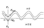
目前,主要使用支架来实现球囊血管成形术后的夹层的临床处理。如图1所示,支架3是定尺寸为动脉7的直径的管。支架在夹层位置处放置在动脉中,以迫使夹层片抵住血管内壁。支架通常由金属合金制成。他们有不同程度的柔性、可视性以及不同的放置技术。支架放置在身体中的各血管床里。支架的发展显著改变了血管疾病的微创治疗方法,使其更安全并且在许多情况下更耐用。使用支架显著降低了球囊血管成形术之后的急性闭塞的发生率。Currently, stents are mainly used to achieve clinical management of dissections after balloon angioplasty. As shown in FIG. 1 , the
然而,支架有显著的缺点,并且正在进行许多研究和发展以解决这些问题。支架诱发经治疗的血管重复狭窄(复发性狭窄)。复发性狭窄是支架的“阿克琉斯之踵(Achilles heel)”。取决于动脉的位置及大小,可能发生内膜增生组织从支柱之间的血管壁或穿过支架中的开口向内生长,并且由于支架狭窄及闭塞导致血管重建失败。这可能在支架置入后的任何时间发生。在许多情况下,支架自身似乎刺激了引起狭窄的局部血管壁反应,甚至是在最初的支架手术期间并不特别狭窄或患病的动脉部分上放置的部分支架中亦是如此。血管对支架的存在的这种反应可能是因为支架的脚手架效应(scaffolding effect)。复发性狭窄或血管内的组织的生长的这种反应是对支架的反应。这种活动表明如同使用支架所发生的那样,在动脉中广泛使用金属和血管覆盖有助于变狭窄。复发性狭窄是个问题,因为它导致支架失效及治疗无效。用于解决这一问题的现有的治疗方法包括:重复血管成形术、切割球囊成形术、低温血管成形术、粥样斑块切除术以及甚至重复支架术。这些方法都不具有高度的长期成功率。However, stents have significant disadvantages, and much research and development is underway to address these issues. Stents induce repeated narrowing of treated blood vessels (recurrent stenosis). Recurrent stenosis is the "Achilles heel" of stents. Depending on the location and size of the artery, in-growth of hyperplastic tissue from the vessel wall between struts or through openings in the stent may occur and vessel reconstruction fails due to stenosis and occlusion of the stent. This can happen any time after the stent is placed. In many cases, the stent itself appears to stimulate the local vessel wall response that causes the stenosis, even in partial stents placed on portions of the artery that were not particularly narrow or diseased during the initial stent procedure. This response of the vessel to the presence of the stent may be due to the scaffolding effect of the stent. This response to recurrent stenosis or growth of tissue within the vessel is a response to the stent. This activity suggests that extensive use of metal and blood vessel coverage in the artery contributes to narrowing, as occurs with stents. Recurrent stenosis is a problem because it leads to stent failure and ineffective treatment. Existing treatments to address this problem include: repeat angioplasty, cutting balloon angioplasty, cryogenic angioplasty, atherectomy, and even repeat stenting. None of these approaches have a high long-term success rate.
支架也可能由于材料应力而断裂。支架断裂可伴随慢性材料应力发生并且与支架断裂的部位处的复发性狭窄的发展相关联。这是相对较新的发现并且可能对于每个血管床中的每种应用需要专门的支架设计。支架的结构完整性对其使用来说仍然是个当前问题。特别是活动的动脉例如下肢动脉和颈动脉特别受到关注。整个支架的完整性在血管弯曲或被压缩的任意时间、沿着支架部分的任意位置进行测试。可能发生支架断裂的一个原因是对比需要治疗的动脉长的一段动脉进行治疗。支架的脚手架效应影响动脉的整体力学行为,使得动脉的柔性下降。可获得的支架材料具有有限的弯曲循环并且容易在反复高频弯曲部位处失效。Stents may also fracture due to material stress. Stent fracture can occur with chronic material stress and is associated with the development of recurrent stenosis at the site of stent fracture. This is a relatively new discovery and may require a specialized stent design for each application in each vascular bed. The structural integrity of stents remains an ongoing issue for their use. In particular, active arteries such as arteries of the lower extremities and carotid arteries are of particular interest. The integrity of the entire stent is tested at any point along the stent section at any time the vessel is bent or compressed. One reason stent fracture may occur is when a segment of an artery is treated that is longer than the artery that requires treatment. The scaffolding effect of the stent affects the overall mechanical behavior of the artery, reducing the flexibility of the artery. Available stent materials have limited bending cycles and are prone to failure at sites of repeated high frequency bending.
许多动脉部分甚至在不需要支架的情况下仍然用支架支承,从而加剧了支架的缺点。这有若干原因。许多情况下需要植入多于一个的支架并且经常需要若干个。支架长度的大部分通常放置在不需要支架并且仅仅与夹层或发病区相邻的动脉部分上。对病变区的精确长度进行调节的支架无法得到。当人们试图放置多个支架并且放置在最需要植入的部段中时,由于每个支架都需要安装和材料而导致成本高昂。为此所花费的时间同时也增加了手术成本和风险。动脉的接收不需要的支架的长度越长,赋予动脉的刚性就越大,并且会产生更多的脚手架效应。这可能有助于刺激动脉对支架的反应,导致复发性狭窄。Many arterial sections are still stented even when they are not needed, exacerbating the disadvantages of stents. There are several reasons for this. Many situations require more than one stent to be implanted and often several are required. The majority of the stent length is usually placed on the portion of the artery that does not require a stent and is only adjacent to the dissection or diseased area. A stent that adjusts to the exact length of the lesion is not available. When one attempts to place multiple stents and place them in the segment where implantation is most needed, it is costly due to the installation and materials required for each stent. The time spent doing so also increases the cost and risk of the procedure. The greater the length of the stent that is not required for the reception of the artery, the more rigidity is imparted to the artery and the more scaffolding effect is created. This may help stimulate the artery's response to the stent, leading to recurrent narrowing.
发明内容Contents of the invention
存在有对发展新的并且改进了的装置以协助治疗包括动脉粥样硬化的血管疾病等其他情况以及例如上文所述的目的的持续需要。There is a continuing need to develop new and improved devices to assist in the treatment of other conditions, including atherosclerosis, and for purposes such as those described above.
在一实施方式中,提供了输送血管假体的系统,该系统包括长形本体、鞘以及多个血管内钉。长形本体具有近端部、远端部及靠近远端部布置的多个输送平台。每个输送平台包括在环形标记带的远端延伸的凹槽。鞘具有近端部、远端部和在近端部与远端部之间延伸的长形本体。鞘能够相对于长形本体从第一位置移动到第二位置。在第一位置,鞘的远端部布置在最远端输送平台的远端。在第二位置,鞘的远端部布置在至少一个输送平台的近端。血管内钉中的每个绕相对应的输送平台布置。In one embodiment, a system for delivering a vascular prosthesis is provided that includes an elongate body, a sheath, and a plurality of intravascular staples. The elongated body has a proximal end, a distal end, and a plurality of delivery platforms disposed proximate to the distal end. Each delivery platform includes a groove extending at the distal end of the annular marker band. The sheath has a proximal end, a distal end, and an elongated body extending between the proximal end and the distal end. The sheath is movable relative to the elongate body from a first position to a second position. In the first position, the distal portion of the sheath is disposed distal to the most distal delivery platform. In the second position, the distal portion of the sheath is disposed proximally of the at least one delivery platform. Each of the intravascular staples is disposed about a corresponding delivery platform.
在某些实施方式中,该系统构造为在间隔开的位置处在治疗区域放置至少两个钉。当这样放置时,在治疗区域中在近端钉的远端部与远端钉的近端部之间可以提供最小间隙。有利地,可以在不需要移动长形本体或输送平台的情况下提供最小间隙。In certain embodiments, the system is configured to place at least two staples in the treatment area at spaced apart locations. When so placed, a minimal gap may be provided in the treatment area between the distal end of the proximal staple and the proximal end of the distal staple. Advantageously, minimal clearance may be provided without the need to move the elongated body or delivery platform.
该间隙有利地使两个钉将引起血管内的扭结或由于过于靠近而产生的其它疾病的机会最小化。This gap advantageously minimizes the chance that the two staples will cause a kink in the blood vessel or other maladies from being too close together.
在每个环形标记带的相邻远端面之间提供了的最小间距,以最小化长形本体的运动,从而确保所部署的钉的最小间隙。例如,在某些实施方式中,与输送平台上的钉的间距相比较,被部署的钉的轴向间距基本没有变化。因此,远端面的最小间距能够有助于防止相邻的钉的过近的部署情况。A minimum spacing is provided between adjacent distal faces of each annular marker band to minimize movement of the elongate body to ensure minimal clearance of the deployed staples. For example, in certain embodiments, the axial spacing of the deployed staples is substantially unchanged compared to the spacing of the staples on the delivery platform. Thus, the minimum spacing of the distal faces can help prevent too close deployment of adjacent staples.
一种维持最小间距的方法——例如使未部署的钉与已部署的钉之间的间距的变化最小化——是提供固定输送系统的近端部的固定装置,使得系统的运动可以集中在鞘中并且使得如果允许长形本体的任何运动,该运动是小的。One approach to maintaining a minimum spacing—for example, minimizing the variation in spacing between undeployed staples and deployed staples—is to provide a fixation that secures the proximal end of the delivery system so that movement of the system can be focused on the in the sheath and such that any movement of the elongated body is small, if allowed.
另外的方法涉及提供布置在输送系统外表面上的稳定装置,以使输送平台中的至少一个输送平台的轴向移位或径向移位中的至少一个移位最小化。A further method involves providing a stabilizing device arranged on an outer surface of the conveying system to minimize at least one of axial or radial displacement of at least one of the conveying platforms.
在另一实施方式中,提供了一种用于放置血管内钉的方法。提供了一种导管系统,该导管系统具有长形本体,该长形本体具有靠近长形本体的远端部分布置的多个间隔开的输送平台。所述的输送平台中的至少一个输送平台的位置通过标记带进行标示。每个平台具有布置在其上的斑块钉。长形本体的远端部分被推进通过患者的脉管系统,直到标示带位于包括夹层斑块的治疗区域的远端或近端为止。标示带是可视化的,以确认所述输送平台中的至少一个输送平台相对于夹层斑块的位置。在保持长形本体的位置的同时,外部鞘缩回,并且之后至少两个钉在预先确定的位置和间距处布置到钉的位置。In another embodiment, a method for placing an intravascular staple is provided. A catheter system is provided having an elongate body with a plurality of spaced apart delivery platforms disposed proximate to a distal portion of the elongate body. The position of at least one of the delivery platforms is marked by a marking tape. Each platform has plaque spikes disposed thereon. The distal portion of the elongate body is advanced through the patient's vasculature until the marker band is distal or proximal to the treatment area including the dissection plaque. A marker band is visualized to confirm a position of at least one of the delivery platforms relative to the dissection plaque. While maintaining the position of the elongated body, the outer sheath is retracted, and at least two staples are thereafter deployed to the staple positions at a predetermined position and spacing.
在各种方法中,可以在钉部署之前部署稳定装置。可以通过对布置在导管系统的远端部处的稳定装置进行致动或通过在近端部将长形本体联接到固定装置而固定长形本体,以使在输送平台附近在长形本体的远端部处夫人血管内的不必要的移位最小化。In various approaches, the stabilizing device may be deployed prior to nail deployment. The elongated body may be secured by actuating a stabilizing device disposed at the distal end of the catheter system or by coupling the elongated body to a fixation device at the proximal end such that the elongated body is near the delivery platform distal to the elongated body. Unwanted displacement within the vessel at the end is minimized.
在另一实施方式中,提供了用于输送血管假体的系统,该系统包括长形本体、长形袋和鞘。长形本体包括远端部、近端部及靠近远端部布置的柱塞。长形袋具有与其联接的多个血管内钉。钉沿着长形袋的长度布置。鞘具有近端部及远端部并且能够相对于长形本体从第一位置移动到第二位置,其中,在第一位置,鞘的远端部布置在长形袋的至少一部分的远端,在第二位置,鞘的远端部布置在长形袋的近端。长形袋构造成在部署期间保持相邻钉之间的最小间距,并且允许扩张以及从长形本体分离。长形袋构造成在部署后释放钉,以朝向血管壁扩张。In another embodiment, a system for delivering a vascular prosthesis is provided that includes an elongated body, an elongated bag, and a sheath. The elongated body includes a distal portion, a proximal portion, and a plunger disposed proximate to the distal portion. The elongated bag has a plurality of intravascular staples coupled thereto. The pegs are arranged along the length of the elongated bag. the sheath has a proximal end and a distal end and is movable relative to the elongated body from a first position to a second position, wherein in the first position the distal end of the sheath is disposed distal to at least a portion of the elongated bag, In the second position, the distal portion of the sheath is disposed proximally of the elongated bag. The elongate pocket is configured to maintain a minimum spacing between adjacent staples during deployment and to allow expansion and separation from the elongate body. The elongated bag is configured to release the staples to expand toward the vessel wall after deployment.
管腔内卡钉可以包括近端周向构件及远端周向构件。近端部周向构件可以部署在管腔内卡钉的近端部处。远端周向构件可以布置在管腔内卡钉的远端部处。在一些实施方式中,远端周向构件是管腔内卡钉的最远端方面,而近端周向构件是管腔内卡钉的最近端方面。近端周向构件和远端周向构件可以通过桥接构件连接。桥接构件可以包括一个或更多个锚定件,该锚定件构造成接合斑块和/或血管壁。该锚定件可以是与钉的其余部分不同的增加的材料厚度,这增加了锚定件的射线不透性并消除了对分离的可视性标记的需求。The intraluminal staple may include a proximal circumferential member and a distal circumferential member. The proximal circumferential member can be deployed at the proximal end of the intraluminal staple. The distal circumferential member may be disposed at the distal end of the intraluminal staple. In some embodiments, the distal circumferential member is the most distal aspect of the endoluminal staple and the proximal circumferential member is the most proximal aspect of the endoluminal staple. The proximal and distal circumferential members may be connected by a bridging member. The bridging member may include one or more anchors configured to engage plaque and/or vessel walls. The anchor can be of increased material thickness different from the rest of the staple, which increases the radiopacity of the anchor and eliminates the need for a separate visibility marker.
附图说明Description of drawings
下面参照优选实施方式的附图来描述这些及其它特征、方面及优点,这旨在说明而并非限制本发明。These and other features, aspects and advantages are described below with reference to the accompanying drawings of preferred embodiments, which are intended to illustrate rather than limit the invention.
图1示出了如在现有技术中通常实施的在血管成形术之后安装的支架的使用。Figure 1 illustrates the use of a stent installed after angioplasty as commonly practiced in the prior art.
图2示出了在腔内处理之后安装的、展现了优于现有技术的优点的斑块钉的使用。Figure 2 illustrates the use of plaque tacks installed after endoluminal treatment exhibiting advantages over the prior art.
图3A以端视图示出了斑块钉的实施方式,图3B以侧视图示出了该斑块钉,图3C以立体图示出了斑块钉,及图3D以平面或展开视图示出了斑块钉的一部分。3A shows an embodiment of a plaque tack in end view, FIG. 3B shows the plaque tack in side view, FIG. 3C shows the plaque tack in perspective view, and FIG. 3D shows it in plan or unfolded view. Figure shows a portion of a plaque tack.
图4是输送装置的已经推进到治疗部位且在血管中扩张的远端部分的示意性图示。4 is a schematic illustration of a distal portion of a delivery device that has been advanced to a treatment site and expanded in a blood vessel.
图4A示出了输送装置的一个实施方式的近端部。Figure 4A shows the proximal end of one embodiment of a delivery device.
图4B是图4中所示的输送装置的远端部分的平面图。4B is a plan view of the distal portion of the delivery device shown in FIG. 4 .
图4C是图4B中的远端部分的截面视图,其示出了准备好植入的多个钉装置。4C is a cross-sectional view of the distal portion of FIG. 4B showing the plurality of staple devices ready for implantation.
图4D示出了在鞘缩回时部署两个钉装置。Figure 4D shows the deployment of the two staple devices when the sheath is retracted.
图5A和图5B分别示出了处于塌陷状态和扩张状态的斑块钉的另一实施方式。5A and 5B illustrate another embodiment of a plaque tack in a collapsed and expanded state, respectively.
图5C示出了图5A至图5B中的斑块钉的一部分的细节图。Figure 5C shows a detail view of a portion of the plaque tack of Figures 5A-5B.
图5C1示出了图5A到图5C的实施方式的变型,其中,该变型具有加大的锚定件。Figure 5C1 shows a variation of the embodiment of Figures 5A to 5C with an enlarged anchor.
图5D示出了图5A到图5C的实施方式的变型、其中,该变型具有布置在钉的中线上的锚定件。Figure 5D shows a variation of the embodiment of Figures 5A-5C with the anchor disposed on the midline of the staple.
图5E示出了具有支柱的变型,其中,该支柱从钉的侧边缘处的较宽部向支架的中间部分处的较窄部渐缩和/或从支架的中间部分处的较窄部向钉的中间位置附近的较宽部渐缩。Figure 5E shows a variation with struts that taper from a wider portion at the side edges of the nail to a narrower portion at the middle portion of the stent and/or from a narrower portion at the middle portion of the stent to a narrower portion at the middle portion of the stent. The wider portion near the middle of the nail tapers.
图6A是对斑块钉与支架的扩张力进行比较的图表。Figure 6A is a graph comparing expansion forces of plaque staples and stents.
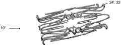
图6B示出了与典型的支架相比在治疗部位的长度上间隔开的多个斑块钉的使用。Figure 6B illustrates the use of multiple plaque staples spaced apart the length of the treatment site compared to a typical stent.
图7A示出了处于完全压缩状态下的斑块钉的另一实施方式。图7D示出了处于完全扩张状态下的斑块钉,以及图7B及图7C示出了处于完全压缩状态与完全扩张状态之间的扩张状态下的斑块钉。Figure 7A shows another embodiment of a plaque tack in a fully compressed state. Figure 7D shows the plaque tack in a fully expanded state, and Figures 7B and 7C show the plaque tack in an expanded state between the fully compressed state and the fully expanded state.
图8是图7A至图7D中的斑块钉的病灶提升元件的示意图。Fig. 8 is a schematic diagram of the lesion-lifting element of the plaque tack in Figs. 7A-7D.
图9是示出了用于计算由于在斑块钉装置中使用了病灶提升元件而产生的被提升的钉的表面的变量的示意图。Figure 9 is a schematic diagram showing variables used to calculate the surface of the lifted staple resulting from the use of a lesion lifting element in a plaque tacking device.
图10示出了具有用于保持斑块抵住血管壁的病灶提升元件的斑块钉的使用。Figure 10 illustrates the use of a plaque tack with a lesion lifting element for holding plaque against the vessel wall.
图11和图12示出了斑块钉上的病灶提升元件的变化使用。Figures 11 and 12 show variations of the use of a lesion lifting element on a plaque tack.
图13和图14示出了斑块钉上的病灶提升元件的另一变型。Figures 13 and 14 show another variation of a lesion lifting element on a plaque tack.
图15示出了用于将动脉壁重新塑造为所需的截面形状的病灶提升元件的使用。Figure 15 illustrates the use of a lesion-lifting element to reshape the arterial wall into a desired cross-sectional shape.
图16至图22示出了在斑块钉的支柱上形成和定位病灶提升元件的变型。Figures 16-22 show variations of forming and positioning a lesion-lifting element on the strut of a plaque tack.
图23至图29示出了将斑块钉输送到血管中的方法。23-29 illustrate methods of delivering plaque staples into blood vessels.
图30A至图30B示出了接合斑块的病灶提升元件。Figures 30A-30B illustrate a lesion-lifting element engaging a plaque.
图31A至图31B示出了接合斑块的锚定件。31A-31B show anchors engaging plaques.
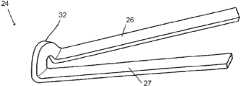
图32A至图32B分别示出了用于输送血管假体的系统的近端视图和远端视图,其中,该系统的鞘的远端部布置在一个或更多个斑块钉的远端。32A-32B show proximal and distal views, respectively, of a system for delivering a vascular prosthesis with a distal portion of a sheath disposed distal to one or more plaque tacks.
图33A至图33B示出了图32A至图32B中的系统的近端视图和远端视图,其中,该系统的鞘的远端部布置在一个或更多个斑块钉的近端。33A-33B show proximal and distal views of the system of FIGS. 32A-32B with the distal portion of the system's sheath disposed proximally of one or more plaque staples.
图34示出了用于输送血管假体的系统。Figure 34 shows a system for delivering a vascular prosthesis.
图35示出了可以用于保持及部署一个或更多个钉的鞘。Figure 35 shows a sheath that can be used to hold and deploy one or more staples.
图36至图36A示出了可以具有环绕布置在图35中所示的鞘内的一个或更多个斑块钉的长形体的一个实施方式。FIGS. 36-36A illustrate one embodiment that may have an elongated body surrounding one or more plaque staples disposed within the sheath shown in FIG. 35 .
图37A至图37B示出了输送系统的变型,其中,设置有主动致动构件,以将该系统锚定在治疗区附近。Figures 37A-37B illustrate a variation of the delivery system in which active actuation members are provided to anchor the system near the treatment area.
图38示出了输送系统的变型,其中,设置有联动装置,以主动致动定位在治疗区附近的构件。Figure 38 shows a variation of the delivery system in which a linkage is provided to actively actuate components positioned near the treatment volume.
图39至图40示出了具有用于稳定远端输送区域的被动扩张构件的输送系统。39-40 illustrate a delivery system with a passive expansion member for stabilizing the distal delivery region.
图41示出了具有用于稳定远端部输送区域的摩擦隔离鞘的输送系统。Figure 41 shows a delivery system with a friction isolation sheath for stabilizing the distal delivery region.
图42示出了包括用于维持相邻的假体之间的间距的可部署的袋的输送系统。Figure 42 shows a delivery system including a deployable bag for maintaining spacing between adjacent prostheses.
图43示出了适于维持相邻的血管假体之间的间距的部署包的一个实施方式。Figure 43 illustrates one embodiment of a deployment package adapted to maintain spacing between adjacent vascular prostheses.
图44示出了包括用于维持邻近的假体之间的间距的可部署的包袋的、具有布置在钉的内部的约束部件的输送系统。FIG. 44 illustrates a delivery system with constraining members disposed inside staples including a deployable bag for maintaining spacing between adjacent prostheses.
图45示出了被优化用于部署斑块钉以刺激斑块与斑块锚定件固件旋转结合的球囊。Figure 45 shows a balloon optimized for deployment of plaque tacks to stimulate rotational engagement of plaque with a plaque anchor fixture.
图45A示出了用于部署多个钉的球囊。Figure 45A shows a balloon used to deploy multiple staples.
图46至图48D示出可以与在本文中公开的任何输送系统一起使用的部署系统的一部分。46-48D illustrate a portion of a deployment system that may be used with any of the delivery systems disclosed herein.
图49示出了梭形部署装置。Figure 49 shows a shuttle deployment device.
具体实施方式Detailed ways
本申请的主题涉及对斑块钉或卡钉装置的改进。该斑块钉或卡钉装置可以用来治疗动脉粥样硬化闭塞性疾症。斑块钉可以用来保持松动的斑块抵住血管壁。斑块钉可以包括构造成对松动的斑块施加扩张力的环形构件。The subject matter of this application relates to improvements in plaque staple or staple devices. The plaque tack or staple device can be used to treat atherosclerotic occlusive disease. Plaque tacks can be used to hold loose plaque against the vessel wall. A plaque tack may include an annular member configured to apply a dilating force to loosened plaque.
I.腔内钉治疗的概述I. Overview of Endovascular Nailing Treatment
图2示出了斑块钉或卡钉装置设备5的一种实施方式,该斑块钉或卡钉装置设备5包括由耐用柔性材料制成的薄的环形带或圆环。该钉装置能够以压缩状态插入血管中并且通过利用导管输送机构在一个或更多个特定的斑块疏松位置处以扩张状态抵住血管壁安装。斑块钉5可以在血管成形术之后部署或作为血管成形术的一部分来部署。斑块钉5适于对血管壁7中的斑块施加扩张力,以抵着血管壁按压和保持斑块。钉装置在弹簧力或其它扩张力的作用下可以是径向向外可扩张的。优选地,钉5的完全扩张直径比要被治疗的血管的横向尺寸大。如下所述,钉5可以可以有利地部署在非常大范围的血管尺寸中。Figure 2 shows one embodiment of a plaque staple or
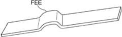
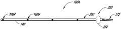
斑块钉5可以包括位于其外环周边上的多个斑块锚定件9。斑块锚定件9可以通过扩张抵住斑块而嵌入斑块或至少放置成与斑块物理接触。在某些实施方式中,斑块锚定件9适于相对于血管壁提升钉5的相邻部分。至少在这种意义上,锚定件9可以具有下面在部分III中讨论的病灶提升元件(focal elevating elements)的一些优点。锚定件9在使与斑块或血管壁的接触的材料表面积的量最小化的同时对斑块施加保持力。作为另一特性,斑块钉5可以仅延伸过血管壁的轴向方向上的小区域,从而使放置在血管中的外来(foreign)结构的数量最小化。例如,每个斑块钉5可以具有轴向长度L,该轴向长度L仅仅是典型支架的轴向长度的一小部分。
如图2所示,本申请的斑块钉装置按照微创手术方法设计以将松动的或夹层(dissected)的动脉粥样硬化斑块钉至动脉壁。斑块钉可以用来治疗原发性动脉粥样硬化病变或球囊血管成形术后的不佳结果。斑块钉设计成在被治疗的动脉中保持足够的腔,而没有血管支架的固有缺点。该装置也可以用于将药、流体或其它治疗(“洗脱(eluting)”)剂施用到动脉粥样硬化斑块或血管壁中或施用到血液中。As shown in FIG. 2 , the plaque tacking device of the present application is designed to staple loose or dissected atherosclerotic plaque to the artery wall according to a minimally invasive surgical approach. Plaque tacks can be used to treat primary atherosclerotic lesions or poor outcomes after balloon angioplasty. Plaque tacks are designed to maintain adequate lumen in the treated artery without the inherent disadvantages of vascular stents. The device may also be used to administer drugs, fluids or other therapeutic ("eluting") agents into atherosclerotic plaque or vessel walls or into the blood.
一个或更多斑块钉5可以精确地沿着斑块堆积部位的长度部署到位,该部位需要特定保持力来稳定该部位和/或保持多片斑块使其不阻挡血液流动的路径。One or
图2示出了在各种斑块钉治疗中,可以将多个斑块钉5部署到沿血管7轴向间隔开的治疗位置。通过这种方式,可以提供靶向治疗以抵住血管壁保持松动的斑块而没有如下文讨论的搭过多支架。斑块钉5和安装过程可以以共用下述通用方法的多种方式设计:该通用方法利用弹簧状环形带的外向力来使得钉能够被压缩、折叠或堆叠为占用小直径体积,从而其可以在鞘或导管上移动到血管中的位置,然后在血管里被释放、展开或解折叠到扩张状态。FIG. 2 illustrates that in various plaque tacking treatments, multiple plaque tacks 5 may be deployed at axially spaced treatment sites along a
斑块钉装置可以从血管内插入点被输送到血管中。部分IV在下面讨论了可以用于布置斑块钉的多种输送方法以及装置。用于不同实施方式的输送方法可以是相同的,或可以由于具有专门设计的以输送专用钉的特征而不同。斑块钉和植入过程可以以共用下述通用方法的多种方式设计:该通用方法利用输送机构(例如球囊扩张)的扩张力和/或可压缩环形带的扩张力以使得钉能够被移动到血管中的位置,然后在血管内被释放、展开或解折叠到扩张状态。A plaque tack device may be delivered into a blood vessel from an intravascular insertion point. Section IV below discusses various delivery methods and devices that can be used to deploy plaque tacks. The method of delivery for different embodiments may be the same, or may differ by having features specifically designed to deliver specific staples. Plaque tacks and implantation procedures can be designed in a variety of ways that share a general approach that utilizes the expansion force of a delivery mechanism (e.g., balloon inflation) and/or the expansion force of a compressible annular band to enable the tack to be Move into position in the blood vessel and then be released, unfolded, or unfolded to an expanded state within the blood vessel.
Π.腔内卡钉的其他实施方式Π. Other embodiments of endoluminal staples
各种斑块钉5可以具有网状构型并且可以设置有一个或更多个周向构件等其他设计,所述周向构件形成有分离的支柱,例如为打开和闭合的细胞构型。Various plaque tacks 5 may have a mesh configuration and may be provided with other designs such as one or more circumferential members formed with discrete struts, eg in an open and closed cellular configuration.
A.具有金属网结构的斑块钉A. Plaque Nails with Metal Mesh Structure
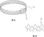
图3A至3D示出了形式为金属网结构的斑块钉10的实施方式。斑块钉10示出为具有闭合单元结构,该闭合单元结构具有由交错网格形成的环形带10a,以及径向向外延伸的突出部10b。斑块钉10可以通过对金属管进行激光切割或蚀刻而制成或由成圈的并且交叉成网的细金属线制成,其中,该细金属线被焊接、钎焊、绕成圈和/或连接到一起成为所需的网状,如在图3C至3D中可以看到的。突出部10b能够从环形带10a突出。突出部10b能够位于钉的外表面上并且能够接触和/或嵌入到血管壁中。Figures 3A to 3D illustrate an embodiment of a
斑块钉10的环形带在血管壁的轴向方向上的尺寸(在本文中,有时被称为长度)能够近似等于或小于其扩张后的直径,以使外来搭架结构在血管中的安放位置最小化。扩张后的直径是指不受约束的扩张后的最终直径。可以将一个或更多个钉仅应用在沿着斑块堆积部位的长度的、需要特定的保持力来稳定部位和/或保持多件斑块以使其不阻挡血液流动路径的位置。The size of the annular band of the
网状式样可以被设计成使得斑块钉10能够被径向向内压缩成较小的体积尺寸。这可以允许斑块钉10被加载到要被插入血管中的导管输送装置上或该导管输送装置内。例如,斑块钉10可以呈具有弯曲部分的整体圆形形状,例如内V形弯曲部分,其中,该弯曲部分使得钉10能够以之字形(zig-zag)折叠成压缩的较小体积形式以装载到例如部署管的输送导管中。The mesh pattern can be designed to enable plaque tacks 10 to be compressed radially inward to a smaller volumetric size. This may allow the
在血管中所需的位置处,压缩的斑块钉10从输送导管释放。呈现环形圈状形状的网格可以允许斑块钉10弹回到其扩张的形状。可替代地,钉10可以通过另一装置例如球囊来扩张。图3C示出了停留在其完全扩张状态下的斑块钉10,以及图3D示出了金属网的一部分的细节。At the desired location in the blood vessel, the
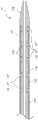
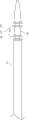
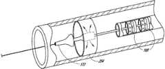
图4到图4D示出了:一个或更多个斑块钉10可以通过带有外部鞘13的输送装置11在治疗部位处定位在患者脉管系统中,并且之后扩张。下面,在第IV部分中讨论输送装置11的改进。钉10可以以任意合适的方式扩张,例如通过被构造成自扩张或通过球囊扩张。在示出的实施方式中,多个自扩张钉10(或变体,例如钉10’或钉10”)布置在鞘13内侧。输送装置11包括至少部分布置在鞘13内的长形本体11A。输送装置11还包括无伤害地移置组织且引导输送装置11通过脉管系统的扩大结构11B。本体11A可以构造有腔11C,腔11C延伸通过本体11A以将引导线40接收在其中并在其中可滑动地推进引导线40。在示出的实施方式中,鞘13与扩大结构11B相接以为输送装置11提供平形的外表面,例如,在其相接处具有相同的外径。本体11A可以构造有多个环形凹槽11D,在该多个环形凹槽11D中布置钉10、10’、10”。环形凹槽11D可以限定在防止钉沿着长形本体11A向近端或远端滑动的肩部11E之间。可以通过设置用于沿着长形本体10A轴向地固定钉10、10’、10’’的其他结构来消除凹槽11D。4 to 4D illustrate that one or more plaque tacks 10 can be positioned in the patient's vasculature at the treatment site by
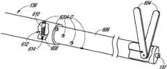
图4A及图4D示出了装置11的近端部和对钉10、10’、10”进行部署的方式。具体地,装置11的近端部包括手柄11F及致动器11G。致动器11G与鞘13的近端部联接,使得致动器11G的向近端和向远端的移动引起鞘13向近端和向远端的移动。图4A示出了致动器11G的远端定位,致动器11G的远端定位对应于鞘13的相对于长形本体11A及凹槽11D的前进位置。在此位置中,凹槽11D及钉10、10’、10”被鞘覆盖。致动器11G相对于手柄11F向近端的移动引起鞘13向近端移动,例如移动到图4D的位置。在此位置,最远端处的两个钉10、10’、10”没有被覆盖并且允许以在本文中讨论的方式自扩张。4A and 4D illustrate the proximal portion of the
现在回到图3A至图3B,钉10的表面上的突出部10b能够用作锚定件或提升元件以嵌入斑块中或压靠斑块。一排锚定件或提升元件可以用于使钉的环形带与斑块群或血管壁联接。突出部10b可以由具有充分刚性的材料制成以维持与血管组织的锁定或接合关系和/或以刺破或接合斑块并且保持与其的锁定或接合关系。突出部10b可以以与环形带的切线成90度的角度突出,或也可以使用锐角。Returning now to Figures 3A-3B, the protrusions 10b on the surface of the staple 10 can be used as anchors or lifting elements to embed in or press against the plaque. An array of anchors or lifting elements can be used to couple the annular band of staples to the plaque mass or vessel wall. The protrusions 10b may be made of a material of sufficient rigidity to maintain a locked or engaged relationship with the vascular tissue and/or to pierce or engage the plaque and maintain a locked or engaged relationship therewith. The protrusion 10b may protrude at an angle of 90 degrees to the tangent of the endless belt, or an acute angle may be used.
斑块钉可以由例如耐腐蚀的金属、聚合物、复合物或其它耐用柔性材料之类的材料制成。优选的材料是具有形状记忆(例如镍钛合金)的金属。在一些实施方式中,钉可以具有约0.1到6mm的长度,大约为1到10mm的扩张后直径,并且从0.01到5mm的锚定件高度。通常,斑块钉的环形带在血管壁的轴向方向上的长度大约等于或小于其直径,以使要安置在血管中的外来结构的数量最小化。环形带可以具有低到1/100的轴向长度与直径之比。Plaque tacks may be made of materials such as corrosion-resistant metals, polymers, composites, or other durable flexible materials. Preferred materials are metals with shape memory such as Nitinol. In some embodiments, the staple may have a length of about 0.1 to 6 mm, a post-dilation diameter of about 1 to 10 mm, and an anchor height of from 0.01 to 5 mm. Typically, the length of the annular band of the plaque tack in the axial direction of the vessel wall is approximately equal to or less than its diameter in order to minimize the amount of foreign structure to be placed in the vessel. The annular band may have an axial length to diameter ratio as low as 1/100.
B.具有开放式单元结构的斑块钉B. Plaque Nails with Open Cell Structure
图5A至图5C示出了在某些实施方式中,斑块钉10’可以构造成具有开放式单元结构。斑块钉10’可以包括呈波浪状——例如正弦曲线——构型并轴向方向上间隔开的一个或更多个周向构件。该周向构件可以通过轴向延伸构件——在本文中有时被称为桥接构件——在沿周向方向间隔开的位置处联接在一起。这些实施方式在大范围的直径上是可扩张的,并且如下面讨论的,可以部署在各种不同的血管中。Figures 5A-5C illustrate that in some embodiments, a plaque tack 10' can be configured with an open cell structure. The plaque tack 10' may include one or more circumferential members having an undulating, e.g., sinusoidal, configuration and spaced apart in an axial direction. The circumferential members may be coupled together at locations spaced apart in the circumferential direction by axially extending members, sometimes referred to herein as bridging members. These embodiments are expandable over a wide range of diameters and, as discussed below, can be deployed in a variety of different blood vessels.
斑块钉10’可以具有类似于上述斑块钉10的特点。例如,斑块钉10’也可以通过对金属管形式进行激光切割或蚀刻而制成。同样地,斑块钉10’可以由例如耐腐蚀金属(例如,特殊涂层或未图层的不锈钢或钴铬合金)、聚合物、复合物的或其它耐用柔性材料之类的材料制成。优选的材料是具有“形状记忆”的金属(例如镍钛合金)。The plaque tack 10' may have features similar to the
图5A至图5B示出了具有开放式单元布置的斑块钉10’的整体结构。斑块钉10’示出为具有两个周向构件12,该两个周向构件可以是由通过在环12之间延伸的桥接件14连接的多个之字形支柱形成的环。该环和该桥接件沿着钉的外表面限定了有界单元柱16。外表面围绕外周边例如钉10’的外周延伸。单元16中的每个单元的边界由多个构件或支柱构成。如图所示,第二环是第一环的镜像,但第一环和第二环可以是具有不同构型的周向构件。同样,桥接件14可以横跨延伸通过其轴向中点的横向平面而对称,然而其他构型也是可能的。环12可以认为是同轴的,其中该术语被广义地限定为包括具有沿共同的轴线——例如钉10’的中央纵向轴线——布置的旋转中心或质心的两个间隔开的环或结构。Figures 5A-5B illustrate the overall structure of a plaque tack 10' having an open cell arrangement. Plaque tack 10' The ring and the bridge define bounding
图5C是钉10’的一部分的示意性平面图示,其示出了单元16的一部分及其边界的一部分。在一个实施方式中,所示的位于中心线C的右侧的部分是单元16的一半。另一半可以是镜像,如图5A至图5B中所示,倒置的镜像或其他构型。环12的作为单独的单元16的一部分的部分可以限定沿着环的式样重复的部分。在一些实施方式中,环12可以具有以延伸越过单元——例如越过1.5个单元、2个单元、3个单元等——的式样重复的部分。与钉10’的其他特征结合的环12的式样能够使其是沿周向方向可压缩的。通过比较图5A中所示的压缩视图与图5B中所示的扩张视图可以看出压缩状态与扩张状态之间的不同。Figure 5C is a schematic plan illustration of a portion of staple 10' showing a portion of
钉10’的单元16可以通过可以互为镜像的两个环12的一部分来划界。因此,一些实施方式可以通过仅参照钉10’的及单元16的一侧来完全地描述。图5C中所示的环12的一部分具有波状的正弦式样。波状式样可以具有一个或更多个幅值,例如所示出的双幅值构型。The
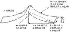
环12可以具有多个支柱或结构构件26、27、28、29。多个支柱可以绕环12的周向重复。支柱可以具有许多不同的形状及尺寸。支柱可以以各种不同的构型延伸。在一些实施方式中,多个支柱26、27、28、29在内顶点18、19与外顶点24、25之间延伸。
在一些实施方式中,外顶点24、25轴向地延伸了当从钉10’的中央区域或中线C测量时的不同距离。具体地,在这方面,顶点24可以认为是高顶点,而顶点25可以认为是低顶点。内顶点18、19可以是轴向对齐的,例如,定位在距中线C的相同轴向距离处。因此,外顶点24与外顶点25相比更远离于桥接件及内顶点布置。在一些实施方式中,钉10’的轴向长度是从在单元16一侧上的外顶点24的顶部到在单元的另一侧上的外顶点24的对应顶部来测量的。换句话说,第一外顶点24从钉10’的中线C延伸了第一轴向距离,而第二外顶点25从钉10’的中心区域C延伸了第二轴向距离,第一距离大于第二距离。如图所示的单元16的各侧具有一个高外顶点24及一个低外顶点25。In some embodiments, the
桥接件14可以连接到内顶点18、19中的一个或更多个。桥接件14可以将两个环12连接起来。桥接件14可以具有许多不同的形状和构型。钉10’的一些实施方式具有近端环及远端环,桥接件布置在近端环与远端环之间并将二者连接。如上面提到的,桥接件14可以位于钉10’的中心区域或中线C处。在图5C中,用词“近端”指的是钉10’上的比被称为“远端”的位置更接近血管接入点部位的位置。然而,钉10’也可以被认为是具有对应于中线C的中间部分以及从其沿两个方向延伸的侧向部分。同样地,被称为“远端”的位置也是中间位置,而被称为“近端”的位置也是侧向位置。可以在本文中使用所有的这些术语。The
如图所示,桥接件14在内顶点18处连接到每个环。在一些实施方式中,桥接件连接到每个内顶点,从而形成闭合式单元结构。在其它实施方式中,桥接件14每隔一个内顶点进行连接、每隔两个内顶点进行连接、或根据需要间隔开更远进行连接,从而形成多个开放式单元结构。桥接件14的数量可以根据应用来选择。例如,当需要限制内膜增生时,可以在两个环12之间使用六个或更少的桥接件14。As shown, a
一种用于增强桥接件14的斑块保持能力的技术是使斑块保持结构(例如下文要讨论的倒钩9、突出部10b、或锚定件)与环121的力施加位置或方向对齐。在一些实施方式中,桥接件14的至少一部分可以与环12的支柱中的一个支柱对齐。例如,当桥接件14连接到环12时,无论在内顶点处或在支柱处,桥接件的该连接部分可以从桥接件以与支柱对齐的、部分对齐的或大致对齐的方式延伸。图5C示出了桥接件14连接到内部顶点18并且桥接件的连接部分与支柱26大致对齐。在一种技术中,桥接件14的斑块保持结构布置在支柱26的纵向轴线LA的突出部上。如下文论述的,钉10’具有多个锚定件20。轴线LA与锚定件20的一部分交叉以使从扩张的支柱26到锚定件20的扭矩作用最大化。在图5C的布置中,位于中心线C的相对侧上的锚定件布置在轴线LA的突出部分上,并且镜像支柱26的纵向轴线LA的突出部分与中心线C的、和如图5C中所示的支柱26的相同侧上的支柱的锚定件20交叉。在另一技术中,支柱26的突出部分及其镜像支柱可以与中心线C对齐,其中支柱26与锚定件20刚性地联接。桥接件14也与钉10’的高幅值正弦曲线部分对齐。One technique for enhancing the plaque retention capabilities of
一系列独特的设计特征可以处出于各种目的而结合到钉10’中,如以下部分中将要详细论述的。例如,钉10’可以包括一个或更多个锚定件、标记及病灶提升元件等其他特征。如上论述的,图5C示出了斑块钉10’可以包括多个(例如,两个)锚定件20。钉10’也可以包括位于每个桥接件14上的位置标记22。位置标记22可以是荧光不透明的并且在一种布置中是大致平形的。如本文中所使用的,平形的标记设置成具有平面外部面,该平面外部面与延伸通过钉10’的外表面的柱面相切或与外表面是同心的但是径向地布置在外表面内。锚定件20同样可以配置成与延伸通过钉10’的外表面的柱面相切。A series of unique design features can be incorporated into the staple 10' for various purposes, as will be discussed in detail in the following sections. For example, the staple 10' may include one or more anchors, markers, and lesion-elevating elements, among other features. As discussed above, Figure 5C shows that the plaque tack 10' can include multiple (e.g., two) anchors 20. Nail 10' may also include
作为另一示例,一系列独特的设计特征可以结合到钉10’中用于动态分布钉10’中的应力。这些设计特征使得能够在压缩、扩张、输送、及导管释放期间对钉10’进行统一控制。设计特征可以还单独地和/或共同地沿着支柱以及在钉与血管内腔的接触面处控制遍布钉的大部分的应力。对应力在钉内的分布的较好控制具有通过限制支柱疲劳以及在钉-血管接触面处的相关联微摩擦来减少细胞反应和钉破裂的好处。微摩擦包括在植入物与患者组织之间的各种小规模的不利交互作用,例如,发生在钉与血管内腔之间的细胞或细胞之间级上的磨损或摩擦。As another example, a series of unique design features can be incorporated into the staple 10' for dynamically distributing stress in the staple 10'. These design features enable unified control of the staple 10' during compression, expansion, delivery, and catheter release. Design features may also individually and/or collectively control stress throughout a substantial portion of the staple along the struts and at the interface of the staple with the lumen of the vessel. Better control of the distribution of stress within the staple has the benefit of reducing cellular responses and staple rupture by limiting strut fatigue and associated microfriction at the staple-vessel interface. Microfriction includes various small-scale adverse interactions between the implant and patient tissue, for example, abrasion or friction that occurs at the cellular or intercellular level between the staple and the lumen of the vessel.
细胞反应的减少被认为是部分地通过减少钉与血管内腔之间的接触表面积以及部分地通过使接触点或结构与血管细胞的自然取向的对准最大化来实现的。因此,钉能够与血管移动,同时减小微摩擦。其它装置——例如支架——以下述方式接触血管细胞:例如,横向地延伸过多个细胞,以增大在支架-血管接触面处的微摩擦。The reduction in cellular response is believed to be achieved in part by reducing the contact surface area between the staples and the lumen of the vessel and in part by maximizing the alignment of the contact point or structure with the natural orientation of the vascular cells. Thus, the staples are able to move with the blood vessel while reducing micro-friction. Other devices, such as stents, contact vascular cells in a manner that, for example, extends laterally across multiple cells to increase microfriction at the stent-vessel interface.
1.单个柱状单元设计1. Single columnar unit design
图5A至5C中所示的钉10’的实施方式的一个特性在于其包括包含在两个之字形环之间的单列开放式单元设计。这种设置提供了血管的最小的(如果有的话)脚手架。在某种意义上,血管接触面积与斑块钉10’的总治疗区域面积之比是小的。关于此点,血管接触面积是钉10’的外部部分可以与血管壁接触的面积的总和。更具体地,血管接触面积可以计算为所有的支柱中的每个支柱的长度乘以每个支柱的径向外表面的平均横向尺寸(宽度)之和。如果支柱的之字形环是激光切割而成的,则支柱的径向外表面的宽度可以小于径向内表面的宽度。血管接触面积还可以包括桥接件14的径向外表面。斑块钉10’的总治疗区域能够相对于完全扩张的构型以最适合的圆筒形限定。最适合的圆筒形是具有与斑块钉10’的无约束周长(unconstrained circumference)相等的内周长的圆筒形。总治疗区域具有限定在斑块钉10’近端部与远端部(或侧部边缘)之间的面积。总治疗区域可以计算为最适合的圆筒形中的近端部与远端部(侧棱)之间的长度与最适合圆筒形的内周长的乘积。在示出的实施方式中,出于确定总的覆盖区域的目的,上述长度可以是环12的高外顶点之间的同一周向位置上的距离。One feature of the embodiment of the staple 10' shown in Figures 5A to 5C is that it comprises a single row open cell design contained between two zigzag rings. This setup provides minimal (if any) scaffolding of the vessels. In a sense, the ratio of the vessel contact area to the total treatment area of the plaque tack 10' is small. In this regard, the vessel contact area is the sum of the areas over which the outer portion of the staple 10' can be in contact with the vessel wall. More specifically, the vessel contact area can be calculated as the sum of the length of each of all struts multiplied by the average transverse dimension (width) of the radially outer surface of each strut. If the zigzag rings of the struts are laser cut, the width of the radially outer surface of the struts may be smaller than the width of the radially inner surface. The vessel contact area may also include the radially outer surface of the
在各种实施方式中,血管接触面积与总治疗区域的比值小于50%。在一些实施方式中,血管接触面积与总治疗区域的比值甚至小于例如40%或更小。血管接触面积与总治疗区域的比值可以小到20%或更小。在特定的示例中,血管接触面积与总治疗区域的比值为5%或甚至2%或更小。如下文所讨论的,病灶提升元件可以增加这种有利特性,甚至通过在周向构件12的至少一部分与血管壁之间提供间隔来更进一步降低血管接触面积与总治疗区域的比值。In various embodiments, the ratio of vessel contact area to total treatment area is less than 50%. In some embodiments, the ratio of vessel contact area to total treatment area is even less than, eg, 40% or less. The ratio of vessel contact area to total treated area can be as small as 20% or less. In certain examples, the ratio of vessel contact area to total treatment area is 5% or even 2% or less. As discussed below, a lesion-elevating element can add to this advantageous property, even further reducing the ratio of vessel contact area to total treatment area by providing spacing between at least a portion of
在某些方法中,可以通过植入多个结构例如斑块钉10’来治疗血管。该结构具有与血管壁的总接触面积。总接触面积可以是各个的结构的血管接触面积之和。在该方法中,总治疗区域面积可以定义为最近端结构的近端部与最远端结构的远端部之间的表面积。在一种方法中,总接触面积不会超过总治疗区域面积的大约55%。更典型地,总接触面积在总治疗区域面积的大约10%与大约30%之间。在特定示例中,总接触面积不超过总治疗区域面积的5%至10%。In some methods, blood vessels may be treated by implanting multiple structures, such as plaque tacks 10'. The structure has a total contact area with the vessel wall. The total contact area may be the sum of the vessel contact areas of the individual structures. In this method, the total treatment area can be defined as the surface area between the proximal portion of the most proximal structure and the distal portion of the most distal structure. In one approach, the total contact area does not exceed about 55% of the total treatment area. More typically, the total contact area is between about 10% and about 30% of the total treatment area. In certain examples, the total contact area is no more than 5% to 10% of the total treatment area.
钉10’也可以理解成在其侧边缘内提供了与支架相比较而相对较高的开放面积。不同于传统的支架,钉10’不需要包括足够的金属来提供脚手架功能以保持血管畅通。为了完成许多预期的治疗,钉10’可以被构造成限制其仅接触单个点或多个分离的点,例如在一个或更多个轴向位置处。分离的点可以通过下述方式大大地间隔开:例如通过在周向上间隔分开或在应用时被血管组织分开的点间隔开。Nail 10' can also be understood as providing a relatively high open area within its side edges compared to the bracket. Unlike conventional stents, the staples 10' need not include sufficient metal to provide a scaffolding function to keep the vessel open. In order to accomplish many contemplated treatments, the tack 10' can be configured to limit its contact to only a single point or a plurality of discrete points, such as at one or more axial locations. The discrete points may be substantially spaced apart, for example by points spaced apart circumferentially or, where applicable, separated by vascular tissue.
在一些实施方式中,如上文限定的,由钉10’的侧部边缘界定的开放面积占总覆盖面积的主要部分。如上文限定的,钉10’的开放面积可以限定为在钉10’处于完全扩张的构型时单元16的面积的总和。开放面积应该在钉10’的外周处进行计算,例如在每个支柱的内侧边缘之间延伸的面积。就此而论,内部侧边缘是形成了单元16的边界的至少一部分的那些边缘。在各种实施方式中,钉10’的支柱的径向向外的表面之和可以不超过钉10’的开放面积的25%。更典型地,钉10’的支柱的径向向外的表面之和介于钉10’的开放面积的约10%到约20%之间。在其它示例中,钉10’的支柱的径向向外的表面之和少于钉10’的开放面积的约2%。In some embodiments, the open area bounded by the side edges of the staples 10' constitutes a major portion of the total coverage area, as defined above. As defined above, the open area of the staple 10' can be defined as the sum of the areas of the
单个柱状设计包括绕钉10’的中心轴线周向地定向的多个钉单元的设置。钉单元可以有多种配置,但是一般包括通过支柱封闭的空间并且布置在钉的壁表面中。开放式单元设计包括下述设置:在这些设置中,近端周向构件和远端周向构件的多个在内部布置的支柱没有通过桥接件或轴连接件连接。图5C示出了内顶点19没有连接到镜像环12的相应的内顶点。因此,单元16的布置在图5C中的内顶点19上方的部分通向单元16的布置在内顶点19下方的部分。开放式单元设计与闭合式单元设计相比能够增强柔性及扩张能力,其中,在闭合式单元中,近端周向构件的每个内置支柱连接到邻近的周向构件的对应的内置支柱。单元16将通过将内顶点19连接到镜像环12的相应内顶点而被分成两个闭合式单元。如上所述,闭合式单元斑块钉可以适合特定症状并且可以包括在本文中描述的其它特征。如图所示,单个柱状开放式单元设计沿着桥接件的中线C(并且,在该实施方式中,还沿着钉10’的圆周)延伸。A single column design includes an arrangement of multiple staple units oriented circumferentially about the central axis of the staple 10'. The tack unit can have a variety of configurations, but generally comprises a space enclosed by a strut and is arranged in the wall surface of the tack. Open cell designs include arrangements in which the multiple internally arranged struts of the proximal and distal circumferential members are not connected by bridges or shaft connections. FIG. 5C shows that
在一个实施方式中,单元16与将绕钉10’的中心轴线的周向布置的多个另外的单元16相同。单元的数量可以根据下述因素而改变:这些因素例如为钉10’被构造所用于的血管的尺寸、环12的优选设置、将要设置的桥接件14的数量及其它因素。In one embodiment, the
如上所述,钉10’可以包括通过桥接件14连接的近端环12及远端环12。近端环12可以布置在钉10’的近端部处。远端环12可以布置在钉10’的远端部处。在一些实施方式中,远端环是钉10’最远的方位,而近端周向构件是钉10’最近的方位。桥接件14可以将钉10’的外表面划分成由桥接件14定界的单元16以及近端环和远端环12中的每个的一部分。在图5A至图5C所示的实施方式中,通过在仅一个轴向位置处提供桥接件和仅一对周向构件或环12来提供单个柱状设计。图5C出于参照目的包括与该示例以及其他示例相关的术语“远端”及“近端”,因此,示出的环12是远端环。在另一实施方式中,示出的环12可以是近端环。As mentioned above, the staple 10' can include a
如上所讨论的,单元16可以具有许多不同形状及构型中的一种。图5B示出了,单元16被对准为沿着钉10’的圆周形成单个柱状开放式单元设计的重复式样。As discussed above,
传统的支架设计从其远端到近端一般是较长的(例如4cm并且当用在外围血管时甚至为20cm)。当设置有周向布置的单元时,传统的支架具有单元形成的大量的柱。这些设计承担着重复的薄弱点并且可以产生变得难以控制的应力。随着装置处于应力及张力之下,这些常规的支架必须在支柱矩阵中获得更大的柔性范围。这些支柱区域吸收整个系统的载荷并在重复外力的周期下开始失效,例如通过冶金摩擦载荷。Traditional stent designs are generally long (eg 4 cm and even 20 cm when used in peripheral vessels) from their distal to proximal ends. When provided with circumferentially arranged cells, conventional stents have a large number of columns formed by the cells. These designs bear repeated points of weakness and can create stresses that become unmanageable. These conventional stents must achieve a greater range of flexibility in the strut matrix as the device is placed under stress and tension. These strut areas absorb the load of the entire system and begin to fail under repeated cycles of external forces, such as through metallurgical friction loading.
钉10’的单个柱状构型没有受到由于远程支架部分的移动而产生的重复薄弱点载荷的影响,这是因为钉不需要轴向地伸长来提供有效的钉式治疗。来自这种短小的其它益处包括降低了其在与血管壁的接触面处以及在输送期间与导管鞘在接触面处的摩擦。如上所述,血管壁接触面处的应力由于缺乏单元对单元的推或拉而被降低,而该单元对单元的推或拉又降低了钉将推或拉相邻的细胞从而沿着腔壁增加细胞炎症或产生组织反应的潜在可能。单个柱状构型或其它轴向短构型也减小了沿着每个支柱的应力,因为单个柱状结构或构型或其它轴向短结构或构型的总长受解剖学组织运动(例如,弯曲,扭转及旋转)的影响较小。这至少部分是由于解剖学组织围绕短结构移动,而较长结构不允许解剖学组织移动并且因此较长结构吸收更多由于解剖学组织运动产生的力。The single column configuration of the staple 10' is not subject to repeated point of weakness loading due to movement of the distal stent portion because the staple does not need to be axially elongated to provide effective staple treatment. Other benefits from this shortness include reduced friction at its interface with the vessel wall and with the introducer sheath during delivery. As mentioned above, the stress at the vessel wall interface is reduced by the lack of cell-to-cell push or pull, which in turn reduces the spikes that will push or pull adjacent cells along the lumen wall. Potential for increased cellular inflammation or tissue response. A single columnar configuration or other axially short configuration also reduces the stress along each strut because the overall length of a single columnar structure or configuration or other axially short structure or configuration is subject to anatomical tissue movement (e.g., bending , torsion and rotation) are less affected. This is at least in part due to the anatomical tissue moving around the short structures, while the longer structures do not allow the anatomical tissue to move and thus absorb more of the forces due to the anatomical tissue movement.
在钉的表面与血管表面之间的任何运动可以引起磨擦和摩擦。如上所述,如果运动很小,则其可以描述为微摩擦。微摩擦会对钉10’及血管的生物细胞产生负面作用。例如,当植入物体的一部分移动而另一部分静止或移动了较小的量时,产生摩擦。长时间的不同量的移动通过例如加工硬化的过程而削弱材料导致断裂。生物细胞由于摩擦而变得受刺激而不适并且通过产生炎症反应来做出反应。炎症会推进包括血管内膜增生和再狭窄的各种不期望的组织学反应。Any movement between the surface of the staple and the vessel surface can cause rubbing and friction. As mentioned above, if the motion is small, it can be described as microfriction. Micro-friction can have a negative effect on the biological cells of the staple 10' and the blood vessel. For example, friction occurs when one part of an implant moves while another part stands still or moves by a small amount. Movement of varying amounts over a long period of time weakens the material through processes such as work hardening leading to fracture. Biological cells become irritated and uncomfortable due to friction and respond by producing an inflammatory response. Inflammation promotes a variety of undesirable histological responses including intimal hyperplasia and restenosis.
2.支柱的控制角度2. The control angle of the pillar
图5C示出了钉10’具有两个周向构件或环12,该两个周向构件或环12各自具有包括α及σ的多个内角。第一角度α限定在支柱26与支柱27之间的第一外顶点24处,而第二角度σ限定在支柱28与支柱29之间的第一外顶点25处。在一些实施方式中,第一角度α可以大于第二角度σ。例如,第一角度α可以介于43°与53°之间或45°与51°之间。第二角度σ可以介于31°与41°之间或33°与39°之间。在一些实施方式中,第一角度α可以是约48°,而第二角度σ可以是约36°。Figure 5C shows that the staple 10' has two circumferential members or rings 12 each having a plurality of interior angles comprising α and σ. A first angle α is defined at a first
在优选实施方式中,钉10’具有7.5mm的扩张后外径,并且第一角度α可以为47.65°而第二角度σ可以为35.56°。在这样的实施方式中,斑块钉10’可以由初始内径为4mm的管材形成。管材可以扩大到7.5mm并且之后在这种形状下进行热处理。在一些实施方式中,斑块钉10’可以由形状记忆材料制成并且热处理步骤可以巩固特殊形状使材料记忆深刻。斑块钉10’随后可以卷曲或压缩并在压缩状态下快速冷冻之后加载到输送装置。In a preferred embodiment, the staple 10' has an expanded outer diameter of 7.5 mm, and the first angle α may be 47.65° and the second angle σ may be 35.56°. In such an embodiment, the plaque tack 10' may be formed from tubing having an initial inner diameter of 4 mm. The tubing can be enlarged to 7.5 mm and then heat treated in this shape. In some embodiments, plaque tacks 10' can be made of a shape memory material and a heat treatment step can consolidate the specific shape to make the material memorable. The plaque tacks 10' can then be crimped or compressed and loaded onto the delivery device after flash freezing in the compressed state.
钉10’的有益特征在于支柱在每个顶点处相交时的角度可以被控制在扩张状态和收缩状态中的至少一个下。例如,外顶点24的内角α、外顶点25的内角σ可以控制成在选定的名义值的±5%之内。这种控制在例如制造斑块钉10’期间的热处理过程中的扩张状态下实现。An advantageous feature of the staple 10' is that the angle at which the struts meet at each apex can be controlled in at least one of an expanded state and a contracted state. For example, the inner angle α of the
已经发现,角度的控制可以有利地缓解制造过程中出现的缺陷。在某些情况下,如果这些角度被充分好地控制,则可以放松对其他尺寸的控制。通过控制这些角度,生产运行质量可以提高。已经发现这样的控制使得能够实现钉10’在制造的弯曲加工周期期间的可重复性、一致性及平衡的可压缩性。这些因素增强生产运行可重复性并且为批量生产提供方便,这使得能够降低该部分的总体成本。It has been found that control of the angle can advantageously mitigate defects that occur during the manufacturing process. In some cases, if these angles are sufficiently well controlled, the other dimensions can be relaxed. By controlling these angles, the quality of production runs can be improved. Such control has been found to enable repeatable, consistent and balanced compressibility of the staple 10' during the bending process cycle of manufacture. These factors enhance the repeatability of production runs and facilitate mass production, which enables the overall cost of the part to be reduced.
另外,对顶点角度的控制使得斑块钉10’能够更好地沿着周向构件或环12分布应力。对顶点角度的控制可以用于以下述方式在环12内控制或分布应力:例如,均匀地沿着支柱的长度或非均匀地控制或分布到可以更有力地应对应力载荷的区域。通过沿着支柱分布应力,钉10’上的有问题的局部应力——例如在易受损坏处——可以在制造的卷边加工过程及扩张期间避免。In addition, control over the apex angle allows the plaque tack 10' to better distribute stress along the circumferential member or
3.倒锥形支柱3. Inverted tapered pillars
在一些实施方式中,例如图5A至图5C中所示,钉10’的一个或更多个支柱26、27、28、29的宽度在不同位置处可以是不同的,例如,可以沿着支柱变化。例如,支柱可以是沿着它们的长度渐缩的。沿着每个装置或沿着每种类型的装置的锥度可以是相同的或不同的。例如,每个周向构件或环12可以由重复支柱的式样组成,其中,每种类型的支柱具有特定的锥度。In some embodiments, such as shown in FIGS. 5A-5C , the width of one or
图5C示出了环12具有与桥接件14联接的第一支柱,其中,该第一支柱渐缩为使得支柱的靠近中线C的部分(在本文中有时称为中间部分或中间位置)比距支柱的中线C间隔更远的部分(在本文中有时称为侧部)狭窄。第二支柱在第一支柱和第二支柱的侧端部处连接到第一支柱。第二支柱可以具有相同的或不同的锥度。例如,第二支柱也可以具有比第二支柱的侧部狭窄的中间部分。另外,第二支柱可以整体上比第一支柱狭窄。第三支柱可以在第二支柱和第三支柱的中间端处连接到第二支柱。第三支柱可以具有比其侧部宽的中间部分。第四支柱可以在第三支柱和第四支柱的侧端部处连接到第三支柱。第四支柱可以具有比其侧部宽的中间部分。第四支柱可以具有与第三支柱相同的或不同的锥度。例如,第四支柱可以整体上比第三支柱宽。5C shows that
图5C示意性示出了一种实施方式中的支柱的宽度的不同。在一些实施方式中,长支柱26和长支柱27在相同的轴向位置处具有相同的宽度,并且短支柱28和短支柱29在相同的轴向位置处具有相同的宽度。支柱26及支柱27可以具有相同的形状。支柱28及支柱29在一些实施方式中具有相同的形状。支柱26、支柱27的形状可以与支柱28、支柱29的形状不同。在一些实施方式中,长支柱26和长支柱27在相同的轴向位置处具有不同的宽度,并且短支柱28及短支柱29在相同的轴向位置处也具有不同的宽度。Figure 5C schematically illustrates differences in the width of struts in one embodiment. In some embodiments, long struts 26 and 27 have the same width at the same axial location, and short struts 28 and 29 have the same width at the same axial location. The
在优选的实施方式中,长支柱26、长支柱27布置在钉10’的与标记22中的一个标记相邻的第一周向位置处。具体地,支柱26具有连接到或形成内顶点18中的一个内顶点的一部分的中间端部,以及远离内顶点18布置的侧端部。该侧端部在外顶点24处或邻近外顶点24联接到支柱27。支柱26邻近中间端部的宽度为W4,而邻近侧端部的宽度为W2。在本实施方式中,支柱26的宽度沿着其长度从宽度W4增大到宽度W2。沿着支柱26的宽度增加优选地沿着其长度是连续的。In a preferred embodiment, the long struts 26, 27 are arranged at a first circumferential position of the staple 10' adjacent to one of the
同样,支柱26的侧部可以相对于支柱26的纵向轴线LA倾斜。例如,布置在支柱26的纵向轴线与支柱27的纵向轴线之间的第一侧部48可以相对于支柱26的纵向轴线以一定角度(例如,不平行地)布置。在另一实施方式中,支柱26的第二侧部46可以相对于支柱26的纵向轴线以一定角度(例如,不平行地)布置。在一实施方式中,支柱的第一侧部48和第二侧部46可以相对于支柱26的纵向轴线以一定角度布置。Likewise, the sides of the
支柱27优选地在沿其长度的不同点处也具有不同的宽度。具体地,支柱27可以沿大致的侧向方向在邻近外顶点24处比在其邻近内顶点19处宽。如上所讨论的,在与支柱26连接时,支柱27可以具有相对于支柱27的纵向轴线成一定角度的侧表面。支柱27在其端部之间可以是渐缩的,例如,具有沿着其长度从靠近外顶点24的较宽部到靠近内顶点19的较窄部而连续递减的宽度。The
支柱28从支柱27或内顶点19延伸。支柱28可以具有比支柱28的侧端部宽的中间端部,并且在沿其长度的不同点处可以具有不同的宽度。侧表面相对于支柱28的纵向轴线也可以是成一定角度的。Strut 28 extends from
最后,支柱29可以在其侧端部处连接到支柱28或外顶点25。支柱29可以具有比其侧端部宽的中间端部。支柱29可以具有与支柱28相同的或不同的锥度。例如,支柱29可以整体上比第三支柱宽。Finally, strut 29 may be connected at its lateral ends to strut 28 or to
在一实施方式中,支柱26可以在靠近外顶点24的侧端部处具有大约0.12mm的宽度W2并在靠近内顶点18的中间端部处具有大约0.095mm的宽度W4,并且支柱28可以在靠近外顶点25的位置处具有大约0.082mm的宽度W6并在靠近内顶点19的位置处具有大约0.092mm的宽度W8。一般而言,W4与W2之间的作为百分比表示的厚度变化可以介于约70%与约90%之间,更典型地介于约75%与约85%之间,并且在特定的实施方式中为约80%。锥形也可以倒置,例如,支架从端部(例如侧边缘)朝向中间部分渐缩。In one embodiment, the
图5E示出了另一变型,其中,钉的一个或更多个支柱的宽度在不同位置处可以是不同的,例如,可以沿着支柱变化。例如,支柱27’可以设置成使得与支柱27相似,除了支柱27’在中间部分N中是最狭窄的。支柱27’可以具有邻近外顶点28的侧宽部分L以及邻近内顶点18的中间宽部分M。支柱27’的宽度沿其长度从侧宽部分L朝向中间部分M减小。在一实施方式中,支柱27’沿着长度从支柱27’的侧端部朝向支柱的中线连续变窄。支柱27’可以变窄为使得支柱27’的中线处的宽度与侧端部处的宽度之比用百分比表示介于约20%与约85%之间。在一些实施方式中,该百分比介于约35%与约75%之间。锥度可以使得该百分比介于约55%与约70%之间。支柱27’可以从中间宽部分沿着其长度变窄。在一实施方式中,支柱27’沿着其长度从其中间端部朝向支柱的中线连续变窄。支柱27’可以变窄为使得支柱27’的中线处的宽度与中间端部处的宽度之比用百分比表示介于约20%与约85%之间。在一些实施方式中,该百分比介于约35%与约75%之间。锥度可以使得该百分比介于约55%与约70%之间。图5E所示的实施方式提供了在较小直径构型中的较大范围的压缩及扩张。较小直径构型可以在较小的体腔例如血管中使用。例如,具有该构型的钉可以由2.3mm直径的管材形成,然而图5C的实施方式可选地由4.5mm直径的管材形成。图5E的构型可以用于制造适用于4弗伦奇(French)输送装置的钉。如图5E中构造的钉可以具有介于约4.5mm与约6.5mm之间的无约束扩张尺寸。在一些实施方式中,包括图5E中的构型的装置可以具有介于约5mm与约6mm之间的无约束扩张尺寸,例如,介于约5.5mm与约6.0mm之间。一实施方式中在无约束的情况下扩张到5.7mm。Figure 5E shows another variation in which the width of one or more legs of the staple can be different at different locations, for example, can vary along the legs. For example, the struts 27' may be arranged so as to be similar to the
独特的倒锥形或沿着支柱的宽度变化通过颠倒锥形在短支柱28、29与长支柱26、27之间的定向来实现。长支柱26、27从靠近内顶点18、19的窄的宽度前进到靠近外顶点24的较宽的宽度。相反地,短支柱28、29是相反的,其中,从靠近内顶点18、19的较宽的宽度到靠近下外顶点25的较窄的宽度。The unique inverted taper or width variation along the struts is achieved by reversing the orientation of the taper between the short struts 28 , 29 and the long struts 26 , 27 . The long struts 26 , 27 progress from a narrow width near the
如上所讨论的,通过对支架宽度的策略性选择,斑块钉也可以分布在压缩过程中和植入后所观察到的应力。这种特征也可以有助于通过沿着支柱的长度更均匀地分布应力区域来控制应力。在一些实施方式中,理想的是将应力非均匀的地分布到能够更好地控制应力的区域。As discussed above, through strategic choice of scaffold width, plaque tacks can also distribute the stresses observed during compression and after implantation. This feature can also help manage stress by more evenly distributing the stress zone along the length of the strut. In some embodiments, it may be desirable to distribute the stress non-uniformly to areas where the stress can be better controlled.
4.双幅值支柱4. Dual Amplitude Pillars
如上所述,图5A至图5C中示出的环12具有波状的正弦式样。环12的轴向延伸可以绕环12的周向变化,例如提供了如从内顶点到邻近的外顶点的距离所测量的多个振幅。波状式样可以具有一个或更多个幅值,例如示出的双幅值构型。在双幅值构型中,多个支柱26、27、28、29在内顶点18、19与外顶点24、25之间延伸。As mentioned above, the
在一些实施方式中,外顶点24、25在高的外顶点24与低的外顶点25之间交替改变。在上下文中,“高”对应于从钉10’的中心区域或中线C所测量的较长的距离H1,而“低”对应于从中线C(图5C)所测量的较短的距离H2。In some embodiments, the
上述的长的和短的正弦支柱的变化的幅值可以提供对斑块钉的功能的额外控制。具体地,当在制造过程中的卷曲加工时,它可以增强钉10’的压缩以提供从完全扩张构型到压缩构型的更大的周向变化。更大的压缩性能促进在小的血管中输送以及更大的可治疗病症区域,这是因为其使得能够实现较小横截面输送系统。The varying amplitudes of the long and short sinusoidal struts described above may provide additional control over the function of the plaque tack. In particular, it can enhance the compression of the staple 10' to provide a greater circumferential change from the fully expanded configuration to the compressed configuration when crimped during manufacture. Greater compressibility facilitates delivery in small blood vessels as well as larger areas of treatable conditions as it enables smaller cross-sectional delivery systems.
顶点的高度H1、H2是从中线C到相应的外顶点24、25的顶部进行测量的。双幅值正弦曲线式样斑块钉10’——例如在图5A至图5C所示的——使得能够实现可以很容易推广到不同外径设计中的广范围的适合尺寸。开放式单元的单个柱状设计允许大范围的压缩及扩张。这部分地是因为适合有效扩张的支柱长度。压缩的容易性与布置在距钉的中心为H1和H2的顶点的位置有关,该位置允许这些顶点在不同位置处而不是在相同的侧部位置处压缩。如果顶点的H1和H2是对齐的(例如,在相同的轴向位置处),它们会在压缩期间压靠彼此,限制了压缩范围。The heights H1 , H2 of the vertices are measured from the center line C to the top of the respective
已经测量出斑块钉10’的压缩范围是0.25倍的公称管尺寸结合扩张范围多达2倍公称管尺寸,尽管这些不是装置的预期范围。结合这些范围,已经测量出压缩的整个压缩范围是热处理外径的0.125倍。如第II部分B.2中所讨论的,在一些实施方式中,公称管尺寸是4.5mm并且管在制造过程中扩张到7.5mm。根据一些实施方式,从装置的中线C到较长的支柱的顶点的距离H1大约是3.0mm,而到较短支柱的顶点的距离H2大约是2.6mm。Plaque tacks 10' have been measured to have a compression range of 0.25 times the nominal tube size combined with an expansion range up to 2 times the nominal tube size, although these are not intended ranges for the device. Combining these ranges, the entire compression range for compression has been measured to be 0.125 times the heat-treated outer diameter. As discussed in Section II B.2, in some embodiments, the nominal tube size is 4.5mm and the tube expands to 7.5mm during manufacture. According to some embodiments, the distance Hi fromthe centerline C of the device to the apex of the longer strut is about 3.0 mm, and the distanceH2 to the apex of the shorter strut is about 2.6 mm.
除了增大压缩率范围,储存在较短幅值支柱中的能量在血管内的输送释放阶段期间提供了对斑块钉10’的额外控制。随着导管鞘缩回,较长支柱首先被移开覆盖物,跟着较短支柱被移开覆盖物(图5C)。这种不匹配提供了较大的保持力以维持斑块钉10’处于输送导管中,并因此在输送期间提供了对斑块钉的更好控制。In addition to increasing the range of compressibility, the energy stored in the shorter amplitude struts provides additional control over the plaque tack 10' during the release phase of intravascular delivery. As the introducer sheath is retracted, the longer struts are unshielded first, followed by the shorter struts (Fig. 5C). This mismatch provides greater retention to maintain the plaque tack 10' in the delivery catheter and thus provides better control of the plaque tack during delivery.
5.居中布置的锚定及提升结构5. Centrally arranged anchoring and lifting structures
图5A至图5C示出了斑块钉10’可以包括居中布置的锚定件20。如上所述,锚定件20主要用于固定松动的斑块,一旦钉10’被置于血管内时,锚定件20的位置和构型就提高了对钉10’的部署和性能的控制。Figures 5A-5C illustrate that the plaque tack 10' can include a centrally disposed
如上所述,斑块钉10’可以是自扩张型周向结构,并且锚定件20可以布置在钉的外侧部分上。锚定件20可以与钉10’的任何部分联接,但优选地靠近桥接件14的中线C布置,如上所述。在一实施方式中,钉10’包括布置在中线C的任一侧上的两个锚定件,如图5C所示。在另一实施方式中,在中线C上可以设置有单个锚定件。在又一实施方式中,可以设置有至少三个锚定件20,例如一个锚定件在中线上而两个锚定件在其任一侧上,如图5C所示。如图5D所示,桥接件14可以在一侧上具有两个锚定件并在另一侧具有连接到另外两个锚定件的一个锚定件。在图5D中,锚定件20’在钉10’的沿其轴向方向的中央处。该实施方式设置有位于中线C的两侧的至少一个锚定件20’。同样的,锚定件20’可以位于标记22的与锚定件20相对的一侧上。这样,斑块可以从多个方向例如多个圆周方向被锚定。在又一实施方式中,不存在锚定件20并且设置有位于中线C上的单个锚定件20’。图5A至图5C所示的实施方式也可以修改为包括在标记22的任一侧上的一个或更多个锚定件,其中,锚定件目前只在一侧上示出。As noted above, the plaque tack 10' can be a self-expanding peripheral structure, and the
在一方面,钉10’的斑块相互作用主要通过锚定件20来提供并且在较小程度上由桥接件14来提供。在一些实施方式中,锚定件可以具有0.01mm到5mm的进入斑块的优选刺入长度。在某些变型中,刺入长度在约0.03mm到约1mm的范围内。在另一变型中,刺入长度在约0.05mm到约0.5mm的范围内。如上所述,可以布置在交替的内顶点处的桥接件14可以构造成在钉10’完全扩张时存在于圆筒形的切面上并且没有因为外部结构而变形。切向构型导致锚定件20从钉10’的圆筒表面向外突出。在该向外突出位置中,锚定件适于接合斑块或其它的血管沉积物,使得血管从其无阻碍的固定状态变化,例如,变化为到不圆。In one aspect, the plaque interaction of staple 10' is provided primarily by
锚定件的切向突出部和桥接件也有利地增强了在部署时对钉10’的控制。用于部署钉10’的技术涉及将钉定位到中空导管体中。如上所述,当定位到导管体中时,钉10’被压缩到压缩状态。环12由于其结构的原因而是高度共形的,如上所述。因此,环完全置于中空导管体的内腔表面对面。相反,桥接件14及锚定件20更具刚性并因此较少共形,并且因此咬入导管体的内腔表面中。这在导管中产生保持力并且限制一些或整个钉10’朝向导管部署区域的非计划中的运动。The tangential projections and bridges of the anchors also advantageously enhance the control of the staple 10' upon deployment. The technique for deploying the staples 10' involves positioning the staples into the hollow catheter body. As mentioned above, when positioned in the catheter body, the staple 10' is compressed into a compressed state.
在一些实施方式中,倒钩20的保持力在部分地部署钉10’后维持不变或增加。具体地,可以在桥接件14与环12的接合点处设置具有相对高柔性的区域。尽管支架的高柔性部段可以是关键区域,由于下述原因这并非斑块钉10’中的情况。至少相较于桥接件14的柔性,柔性区域可以具有加强柔性区域的柔性的任何材料特性或结构,使得当环12在部署的前沿边缘上运动时,不会减弱切向构型及锚定件20要咬入中空长形导管体中的趋势。即使前沿环12可以扩张到其完全扩张后尺寸的至少一半,仍是这种情况。In some embodiments, the retention force of the
如图所示,桥接件14在内顶点18处连接到每个环,其中,在内顶点18处,桥接件14的至少一部分地可以与组成环12的支柱中的一个支柱对齐、部分地对齐或基本上对齐,如上所述。例如,如图所示,桥接件14与式样的高幅值正弦部分对齐。柔性较高的区域可以布置在内顶点18与桥接件14之间。As shown, a
在某些实施方式中,环12的扩张甚至会引起锚定件20向外旋转以增加导管体内的保持力。例如,支柱26的扩张可以引起内顶点18向内偏转。当环12扩张时,会发生锚定件20的轻微旋转,这可以引起前部锚定件的向外扭转以及尾部锚定件的相应向外扭转。参照图5C,如果所描述的环12在移出中空导管体时首先扩张,则中线C的右边的锚定件20可以朝向导管体的中心轴线向内偏转,但是左边的锚定件20将向外偏转,以增加其保持力。因此,斑块钉10’可以在该局部扩张期间保持在导管内。由于该特征,斑块钉10’可以一致地放置,如下面在第II部分.B.8中进一步讨论的。In some embodiments, expansion of the
桥接件14及锚定件20的失圆筒本性(out-of-cylinder nature)也为部署状态提供了益处。具体地,在一些实施方式中,在已扩张状态下,斑块锚定件20径向地布置在由环12形成的圆筒形表面的外部。失圆筒程度可以取决于应用,但是对于在部署时使圆筒形表面的至少一部分与脉管系统的内壁间隔开一般是充分的。这样,锚定件20或与环12结合的锚定件可以构造成病灶提升元件,这将在下面的第III部分进行讨论。The out-of-cylinder nature of
随着斑块钉10’在血管内扩张,支柱将接合血管壁和/或斑块。应该预想到的是在大多数情况下,支柱中的至少一些将随着血管内的不规则形状而变形。同时,桥接件14不易变形并且因此将抵制这种变形而将其保持为圆形构型。由支柱构件施加的向外的力被传递到与血管壁接触的这些区域中。在一些情况下,当钉10’与具有不规则形状的血管内腔符合时,刚性中央锚定件变成为用于血管接触的区域。支柱在环12内累积的外向力通过桥接件14施加到锚定件。邻近的支柱与接触区域分担它们的载荷,使得将血管挤压成扩大构型,例如一致的圆。As the plaque tack 10' expands within the vessel, the struts will engage the vessel wall and/or plaque. It should be expected that in most cases at least some of the struts will deform with irregular shapes within the vessel. At the same time, the
这样的配置可以提供下述益处:例如,有助于使斑块钉10’在输送后保持到位以及允许斑块钉10’动态地响应血管自身的运动和脉搏动。另外,该构型可以具有通过限制支柱疲劳以及加载在钉-血管接触面处的相关联的微摩擦来减少细胞反应以及装置断裂的益处。Such a configuration may provide benefits such as helping to keep the plaque tack 10' in place after delivery and allowing the plaque tack 10' to dynamically respond to the movement and pulse of the vessel itself. Additionally, this configuration may have the benefit of reducing cellular responses and device fracture by limiting strut fatigue and associated microfriction loading at the staple-vessel interface.
在一些实施方式中,桥接件14可以包括一个或更多个锚定件。在一些实施方式中,桥接件可以由完全由锚定件形成。In some embodiments,
在部署斑块钉10’之后,外科医生有下述选择:在钉的位置处放置血管成形球囊并且使球囊扩张以将锚定件20按压到斑块和/或血管壁中。After the plaque tack 10' is deployed, the surgeon has the option of placing an angioplasty balloon at the location of the tack and expanding the balloon to press the
6.平的中线标记6. Flat midline marker
如上所讨论的,斑块钉10’具有一个或更多个标记22。在一实施方式中,一系列不透射线的标记22可以位于钉10’上。在一些实施方式中,不透射线的标记22在装置的中线C处。不透射线的标记22可以布置在两个周向定向的正弦曲线构件或环12之间。Plaque tack 10' has one or
在一些实施方式中,不透射线的标记22(例如,铂或钽)可以邻近斑块锚定件20布置。不透射线的标记22可以具有许多不同形状或构型中的一种。在一些实施方式中,不透射线的标记22具有平面的或平形的构型。如图5C中所示,每个标记22通过例如压配合或铆接而与圆形眼孔联接,形成了具有眼孔的平直表面。标记22在导管输送系统中提供了钉10’的清晰可见性并且在处理期间为临床医生进行准确放置提供导引。In some embodiments, a radiopaque marker 22 (eg, platinum or tantalum) may be placed adjacent to the
根据某些输送方法,由于锚定件20以及标记22在正弦曲线环12之间桥接件14处的共同放置,当将要释放装置时,标记22可以为临床医生提供该点处的可视的线索。例如,当标记22与位于输送导管鞘的顶部处的标记带相遇时,可以部署整个装置。Due to the co-location of the
现在参照图5C1,示出了钉10’的示意性图示。如图所示,锚定件20具有与钉的其它部分不同的增加了的材料厚度。这也使得锚定件20与钉的其它部分相比具有增强了的射线不透性,有效地将锚定件转变成为标记。Referring now to Figure 5C1 , a schematic illustration of a staple 10' is shown. As shown, the
7.装置同时放置在血管中7. Simultaneous placement of the device in the blood vessel
可以将斑块钉10’构造成同时放置在血管内。斑块钉10’的同时放置可以限定为在斑块钉10’的远顶点中的任一个远顶点与其将要放置的血管腔接触之前从输送导管释放整个斑块钉10’。这种情况可以在锚定件20完全没有被导管鞘遮蔽时发生,使得整个斑块钉10’能够抵着血管的腔壁扩张。支柱26、27、28、29可以以下述方式自由浮动:例如,与血管壁间隔开或对壁施加微小的力,使得它们在同时放置之前不接触腔壁。例如,锚定件20可以具有使支柱26、27、28、29与血管壁的一部分或基本上全部间隔开的作用。下面将讨论可以用于将斑块钉10’与腔壁间隔开的病灶提升元件的其他形式。Plaque tack 10' can be configured for simultaneous placement within a blood vessel. Simultaneous placement of the plaque tack 10' may be defined as releasing the entire plaque tack 10' from the delivery catheter before any of the distal apexes of the plaque tack 10' come into contact with the lumen of the vessel in which it will be placed. This can occur when the
同时放置为临床医生提供了对放置进行控制的能力,直到标记22和/或锚定件20不被覆盖为止,这可以产生完整的扩张活动(邻近于或接触腔壁的支柱)。在一些实施方式中,主要由于钉10’的内力促使锚定件20与上述的输送鞘接合,完全扩张活动不会发生,直到锚定件20不被覆盖为止。Simultaneous placement provides the clinician with the ability to control placement until the
同时放置的另一益处在于减少了在放置斑块钉10’期间抵着或沿着腔表面无意拖动或推动支柱。由于疾病的复杂性及变化性、放置的位置及夹层形态,斑块钉10’的外表面同时接触腔壁的能力取决于部署环境。然而,已观察到斑块钉10’在从导管鞘完全释放时在几分之一秒内接触到腔壁的能力。Another benefit of simultaneous placement is the reduction of inadvertent dragging or pushing of the strut against or along the luminal surface during placement of the plaque tack 10'. Due to the complexity and variability of the disease, the location of placement and the morphology of the dissection, the ability of the outer surface of the plaque tack 10' to simultaneously contact the cavity wall depends on the deployment environment. However, the ability of the plaque tack 10' to contact the lumen wall within a fraction of a second when fully released from the introducer sheath has been observed.
8.低斜率力曲线8. Low slope force curve
斑块钉10’的另一独特方面在于可以配置成具有力曲线,该力曲线带有具有低斜率的延伸区域。例如图6A所示,力曲线示出了通过自扩张斑块钉10’或支架在从压缩状态运动到扩张状态时施加的扩张力的量。装置的扩张力可以为对要放置在特定血管中的正确装置进行选择的因素。Another unique aspect of the plaque tack 10' is that it can be configured to have a force curve with an extended region of low slope. For example, as shown in FIG. 6A, the force curve shows the amount of expansion force applied by a self-expanding plaque tack 10' or stent as it moves from a compressed state to an expanded state. The expansion force of the device can be a factor in selecting the correct device for placement in a particular vessel.
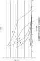
仍然参照图6A,SMART支架(即,Cordis公司的
图6A示出了第一黑线A1,该第一黑线A1示出了7.5mm的斑块钉10’从约7.5mm到约2mm的压缩后直径的压缩。在约7.5mm与约6mm之间的逐渐倾斜区域之后,用于直径的每个进一步减小的力的倾斜大大降低,提供了将钉10’从约6mm完全压缩到约2mm所需的窄的力范围。力曲线的这部分是很平的,这意味着随着钉10’接近其完全压缩状态,所施加的压缩力没有较大的增加。斑块钉10’在从2mm的压缩直径延伸到约7.5mm的扩张直径的扩张期间的力曲线由黑线B1来示出。曲线的这部分可以看作是工作部分,其中,Y轴上的力是斑块钉10’在扩张时将施加到血管壁上的力。例如,如果斑块钉10’在具有约5.0mm孔径的血管内腔中部署时,钉10’在壁上的向外力将很好地在1.0牛顿(N)以下。超过约2mm的范围,向外力的范围少于0.05牛顿(N)±约30%。Figure 6A shows a first black line Al showing compression of a 7.5 mm plaque tack 10' from a post-compression diameter of about 7.5 mm to about 2 mm. After a region of gradual inclination between about 7.5mm and about 6mm, the inclination for each further reduction in diameter is greatly reduced, providing the narrow gap required to fully compress the staple 10' from about 6mm to about 2mm. force range. This portion of the force curve is quite flat, meaning that there is no major increase in the applied compressive force as the staple 10' approaches its fully compressed state. The force curve of the plaque tack 10' during expansion from a compressed diameter of 2 mm to an expanded diameter of about 7.5 mm is shown by the black line Bl. This part of the curve can be considered the working part, where the force on the Y-axis is the force that the plaque tack 10' will exert on the vessel wall as it expands. For example, if a plaque tack 10' is deployed in the lumen of a vessel having a pore size of about 5.0 mm, the outward force of the tack 10' on the wall will be well below 1.0 Newtons (N). Over a range of about 2 mm, the outward force ranges less than 0.05 Newton (N) ± about 30%.
图6A以较暗的线A2示出了在相似的测试中SMART支架的卷曲性能。如以上关于现有技术的支架所讨论的,SMART支架是比斑块钉10’长的结构。具体地,经测试的支架长40mm并具有8mm的无约束外径,而经测试的钉为6mm长并具有7.5mm的无约束外径。然而,应当认为,斑块钉10’与SMART支架之间的对比示出了将仍然证实了SMART支架的可比较的长度形式的差异。如图表所示,线B2具有在从8mm以上到约6.5mm的范围内的较高卷曲力。在大约6.5mm处,卷曲力的斜度减小并且卷曲力以很小的比率增加。处于完全卷曲状态的向外力很高。尽管SMART支架的完全卷曲状态对应于较小的直径,对于可比较的直径的卷曲力在SMART支架上较高。线B2示出了测试的SMART支架的工作区域。线B2示出了超出从约2mm延伸到约6mm范围的向外力。如可以看到的,线B2的斜度在沿着其在2mm和6mm之间的范围内的所有点处是较大的。这种高斜度的实际作用在于SMART支架对其中部署扩张的斑块钉10’的血管的孔径大小的变化是较敏感的。Figure 6A shows the crimping performance of the SMART stent in a similar test as darker line A2. As discussed above with respect to prior art stents, the SMART stent is a longer structure than the plaque tack 10'. Specifically, the tested The stent was 40mm long and had an unconstrained outer diameter of 8mm, while the tested pins were 6mm long and had an unconstrained outer diameter of 7.5mm. However, it is believed that the comparison between the plaque tack 10' and the SMART stent shows differences that would still demonstrate a comparable length form of the SMART stent. As shown in the graph, wire B2 has a higher crimp force ranging from above 8 mm to about 6.5 mm. At about 6.5 mm, the slope of the crimp force decreases and the crimp force increases at a small rate. The outward force in the fully curled state is high. Although the fully crimped state of the SMART stent corresponds to a smaller diameter, the crimp force is higher on the SMART stent for comparable diameters. Line B2 shows the working area of the tested SMART stent. Line B2 shows outward force over a range extending from about 2 mm to about 6 mm. As can be seen, the slope of line B2 is greater at all points along it in the range between 2mm and 6mm. A practical effect of this high slope is that the SMART stent is more sensitive to changes in the pore size of the vessel in which the expanded plaque tack 10' is deployed.
如图可以在6A中所看到的,在一些实施方式中,力曲线的低斜度在超过大约3mm的外径的扩张范围内可以是基本上平的。在其它实施方式中,力曲线的低斜度可以超出2.5mm的外径扩张范围且力的变化的改变小于1N。钉具有较宽范围——径向力变化少于1N——的能力的因素包括中线锚定件、双幅值支柱以及变化的支柱厚度,如上所述。As can be seen in FIG. 6A , in some embodiments, the low slope of the force curve may be substantially flat over a range of expansion beyond an outer diameter of about 3 mm. In other embodiments, the low slope of the force curve may exceed a 2.5 mm outer diameter expansion range with a change in force change of less than 1N. Contributors to the tack's ability to have a wide range of radial force variations of less than 1 N include midline anchors, dual amplitude struts, and varying strut thicknesses, as described above.
图6A示出了具有压缩曲线A3及扩张曲线B3的另一常规支架。该SMART支架具有广泛使用的支架式样。曲线A3、B3表示另一常规支架设计。尽管曲线A3、B3在曲线的左手边处具有较低峰值压缩力,但在使用范围方面,其斜度仍明显地比由曲线A1、B1示出的钉的斜度大。FIG. 6A shows another conventional stent with a compression curve A3 and an expansion curve B3. This SMART stand has a widely used stand pattern. Curves A3, B3 represent another conventional stent design. Although the curve A3, B3 has a lower peak compression force at the left hand side of the curve, its slope is still significantly steeper than that of the nail shown by the curve A1, B1 in terms of the range of use.
当在整个范围内的任意点呈现不超过约5N的径向扩张力时,钉径向地自扩张了至少约2mm的范围,一般至少可自扩张大约3mm并且典型地从扩张了至少约4mm或5mm的范围。在一些实施方式中,整个扩张范围内的最大径向扩张力不超过约4N并且优选地不超过约3N。在一实施方式中,钉在至少约3mm的范围(例如,从约3mm到至少约6mm)上是可扩张的,并且径向扩张力在整个范围内小于约3N。通常扩张力在整个扩张范围内的变化将不会超过约3N,并且优选不超过约2N。在一实施方式中,扩张力从在3mm直径处不超过约2N下降到在6mm直径处不超过约1N。典型地,在整个扩张范围内在任意给定的直径下,压缩径向力与扩张径向力之间的差值不超过约4N,一般不超过约3N,优选地不超过约2N,并且在一实施方式中不超过约1N。在一实施方式中,钉在整个包括3mm到约6.5mm的范围内是可扩张的,并且压缩力与扩张力之间在沿着压缩/扩张范围的每一点处的差值相差不超过约2N并优选不超过约1N。The staples radially self-expand to a range of at least about 2 mm, generally at least about 3 mm and typically at least about 4 mm or 5mm range. In some embodiments, the maximum radial expansion force throughout the expansion range does not exceed about 4N and preferably does not exceed about 3N. In one embodiment, the staple is expandable over a range of at least about 3 mm (eg, from about 3 mm to at least about 6 mm) with a radial expansion force of less than about 3 N throughout the range. Typically the expansion force will vary by no more than about 3N, and preferably no more than about 2N, across the range of expansion. In one embodiment, the expansion force drops from no more than about 2N at a 3mm diameter to no more than about 1N at a 6mm diameter. Typically, the difference between the compressive radial force and the expansive radial force does not exceed about 4N, generally does not exceed about 3N, and preferably does not exceed about 2N at any given diameter throughout the expansion range, and at a In embodiments no more than about 1N. In one embodiment, the staple is expandable throughout a range including 3mm to about 6.5mm, and the difference between the compressive force and the expanding force at each point along the range of compression/expansion does not differ by more than about 2N And preferably no more than about 1N.
通常,斑块钉10’的向外力优选尽可能低,同时提供足够的力以在整个较宽的腔的直径范围内抵靠腔壁保持斑块。当力提高,例如提高到足够的保持力的2到3倍时,会产生不良副作用。这些不良副作用可以包括刺激血管壁的与装置接触的细胞,这可能导致再次变窄。尽管极低力的装置对于典型治疗是优选的,但较高力的装置对于在钙化病变处发现松动斑块的情况下是有用的。In general, the outward force of the plaque tack 10' is preferably as low as possible while providing sufficient force to hold plaque against the lumen wall throughout the diameter of the wider lumen. When the force is increased, for example to 2 to 3 times the adequate holding force, adverse side effects can occur. These adverse side effects can include irritation of cells of the vessel wall that come into contact with the device, which can lead to re-narrowing. Although very low force devices are preferred for typical treatments, higher force devices are useful in cases where loose plaque is found at calcified lesions.
在装置扩张时力缓慢改变的优点是能够预测血管独立于腔直径经历的能量。另一价值是将会减少医院必要的库存。例如,已经发现,在图5A至图5C中示出的钉10’的两部分尺寸可以用于在从臀部到脚踝的整个腿部的血管中的斑块钉治疗。这被认为在很大程度上是因为钉10’具有小于-0.3N/mm的斜度。The advantage of a slow change in force as the device expands is the ability to predict the energy experienced by the vessel independent of lumen diameter. Another value is that it will reduce the necessary inventory in hospitals. For example, it has been found that the two-part size of the staple 10' shown in Figures 5A to 5C can be used for plaque tacking in blood vessels throughout the leg from the hip to the ankle. This is believed to be largely due to the fact that the staple 10' has a slope of less than -0.3 N/mm.
C.斑块钉设计参数C. Plaque Nail Design Parameters
不同于传统的支架植入,本文描述的斑块钉的目的是为了将植入的外来材料的量减到最小减少,同时仍然执行对血管环境的病灶治疗,使得能够引起最小的血管壁反应和不利的术后再狭窄。斑块钉设计成具有大大减少的金属覆盖和/或与血管表面的接触。从而引发更少的急性及慢性炎症(参见图6B)。植入材料抵靠血管壁的减少的接触面积与较低的内膜增生发生率及良好的长期畅通相关。沿血管的轴向距离的明显减少的长度允许有更多的靶向治疗并与血管表面的外来体覆盖有关,并且避免了覆盖不需要覆盖的表面部分并与对血管重建的畅通进行早期和晚期改进有关。Unlike traditional stent implantation, the purpose of the plaque tacks described herein is to minimize the amount of foreign material implanted while still performing focal treatment of the vascular environment, enabling minimal vessel wall reaction and Unfavorable postoperative restenosis. Plaque tacks are designed to have greatly reduced metal coverage and/or contact with vessel surfaces. This results in less acute and chronic inflammation (see Figure 6B). A reduced contact area of the implanted material against the vessel wall is associated with a lower incidence of intimal hyperplasia and good long-term patency. The significantly reduced length of the axial distance along the vessel allows more targeted therapy and is associated with exosome coverage of the vessel surface and avoids covering parts of the surface that do not need to be covered and is associated with early and late patency of vessel remodeling related to improvement.
斑块钉仅在需要钉住已经通过球囊血管成形术或其他机构瓦解的斑块的情况下部署。斑块钉不是覆盖整个治疗区域,而是可以局部地及选择性地放置,例如,不延伸到正常的或少病患的动脉区段(见图6B)。这允许血管保持其天然的柔性,因为当局部使用小轮廓的钉或甚至当多个钉在治疗区域上间隔开时小到没有脚手架。可以通过使用“多点接触”而在病灶点处达到更高的压力以及提升邻近支架部分离开血管壁而减少钉支架结构上的其他处外压力的整体载荷,从而实现压力分布的进一步减少。Plaque staples are only deployed when needed to staple plaque that has been collapsed by balloon angioplasty or other mechanisms. Instead of covering the entire treatment area, plaque tacks can be placed locally and selectively, eg, not extending into normal or less diseased arterial segments (see Figure 6B). This allows the blood vessel to retain its natural flexibility as it is so small that there is no scaffolding when small profile staples are used topically or even when multiple staples are spaced apart over the treatment area. Further reduction in pressure distribution can be achieved by using "multi-point contact" to achieve higher pressures at the lesion point and elevating adjacent stent portions off the vessel wall reducing the overall load of external pressure elsewhere on the nail-stent structure.
用于斑块钉设计的一个参数是不超过约2.0的钉的轴向长度与扩张后直径的(L/D)比,经常不超过约1.5,并且在一些实施中不超过大约1.0。在一实施方式中,钉具有大约0.8的L/D的比率。也就是说,钉沿着血管轴线的长度大约等于或小于钉的扩张后直径。因此,优选的斑块钉定形状为像环形圈或带,然而,典型的支架定形状为像长形的管。因此,小轮廓的钉可以局部用于以最小的外来材料覆盖或接触来对血管表面的中断区域进行靶向治疗。测试显示具有轴向长度/直径≤1的斑块钉与轴向长度大于直径并且通常大许多的传统支架相比,几乎不会引起生物反应及后续血管变窄。测试表明L/D≤1的装置引起了比典型的支架引起的脚手架减少还要少很多,并且引起较小的动脉壁反应。对于球囊血管成形术后在小型夹层部位处的应用,可以使用具有最小占用面积的斑块钉,例如单个的、具有在1/10至1/100范围内L/D比率的薄环型钉。One parameter for plaque staple design is a staple axial length to expanded diameter (L/D) ratio of no more than about 2.0, often no more than about 1.5, and in some implementations no more than about 1.0. In one embodiment, the staples have a L/D ratio of about 0.8. That is, the length of the staple along the vessel axis is approximately equal to or less than the expanded diameter of the staple. Thus, preferred plaque staples are shaped like annular rings or bands, however, typical scaffolds are shaped like elongated tubes. Thus, the low profile staples can be used locally to target treatment of disrupted areas of the vessel surface with minimal foreign material coverage or contact. Tests have shown that plaque staples with axial length/diameter ≤ 1 cause little biological response and subsequent narrowing of the vessel compared to traditional stents whose axial length is greater than diameter and are generally much larger. Tests have shown that devices with L/D ≤ 1 cause much less scaffolding reduction than typical stents and cause less arterial wall response. For application at small dissection sites after balloon angioplasty, plaque staples with minimal footprint can be used, such as single, thin ring staples with L/D ratios in the
对支架的研究已经显示支架的轴向长度与在多个血管区域中的闭塞趋势有关。布置越多的支架轴向长度,重建失败的可能性就越高。当放置在股浅动脉中时,支架的轴向长度也直接关系到支架破损的频率及趋势。医学文献表明股浅动脉类似于橡胶带运行,并且对股浅动脉的自然伸长和收缩进行改变很可能在股浅动脉支架的失效模式中起到重要作用。相反,小轮廓的斑块钉可以仅植入需要使用它们的局部区域中,从而使血管壁能够保持其天然的柔性以甚至在表面经过钉固后进行移动及弯曲。多个钉可以通过没有金属支承的区域分开地植入,从而使动脉更自然地自由弯曲。Studies on stents have shown that the axial length of the stent correlates with the tendency to occlude in multiple vessel regions. The greater the axial length of the stent deployed, the higher the likelihood of reconstruction failure. The axial length of the stent is also directly related to the frequency and tendency of stent breakage when placed in the superficial femoral artery. The medical literature suggests that the superficial femoral artery runs like a rubber band, and that alterations to the natural elongation and contraction of the superficial femoral artery are likely to play an important role in the failure modes of superficial femoral artery stents. In contrast, low profile plaque tacks can be implanted only in the localized areas where they are needed, allowing the vessel wall to retain its natural flexibility to move and bend even after the surface has been stapled. Multiple staples can be implanted separately through areas without metal support, allowing the artery to bend more naturally.
也可以通过小轮廓钉设计大大减小施加在血管壁上的向外的径向压力,甚至当以间隔开的构型使用多个钉时亦是如此。为了最小化这种向外的力同时仍然提供夹层抵住动脉壁的保持力,可以使用一系列的锚定倒钩或病灶提升元件。将病灶压力施加到动脉壁的特征的存在允许其余的钉向动脉壁施加最小的向外的力。施加压力的点可以极其局灶性,并且这是大部分力施加的点。通过钉施加的焦点压力的应用的局灶本性也使装置的结构作用最小化。均匀分布的锚定件或病灶提升元件可以提供径向的能量分布,使得形成环形腔的趋势最大化。The outward radial pressure exerted on the vessel wall can also be greatly reduced by the low profile staple design, even when multiple staples are used in a spaced apart configuration. To minimize this outward force while still providing retention of the dissection against the arterial wall, a series of anchoring barbs or lesion-elevating elements may be used. The presence of features that apply focal pressure to the arterial wall allow the remaining staples to apply minimal outward force to the arterial wall. The point where the pressure is applied can be extremely focal, and this is where most of the force is applied. The focal nature of the application of the focal pressure applied by the staples also minimizes the structural effects of the device. Evenly distributed anchors or lesion-elevating elements can provide radial energy distribution that maximizes the tendency to form an annular lumen.
用于设计斑块钉的另一重要的参数是血管覆盖面积(C)与总的血管表面积(TVS)的比率。在一个定义中,值C是假体(例如,支架或钉)的长度乘以其中放置假体的血管的平均周长,并且值TVS可以是病变区域或需要治疗的区域长度乘以同一公称周长。这也可以简化为假体在扩张到公称周长时的总长度除以血管中的病变的长度的这样的比率。这些概念可以应用到一个钉装置或当横过血管治疗区域的长度布置的若干间隔开的钉装置时应用。当使用多个支架或多个钉时,简化的比率可以是总的未覆盖长度除以病变长度或可以是假体的长度之和除以病变长度的之和。对斑块钉来说,C/TVS比率在大约60%或更少的范围内,然而,对支架来说,其可以是100%或更多(如果应用在覆盖治疗部位)。Another important parameter for designing a plaque tack is the ratio of vessel coverage area (C) to total vessel surface area (TVS). In one definition, the value C is the length of the prosthesis (e.g., a stent or staple) multiplied by the mean circumference of the vessel in which the prosthesis is placed, and the value TVS may be the length of the diseased area or area in need of treatment multiplied by the same nominal circumference long. This can also be simplified as the ratio of the total length of the prosthesis when expanded to nominal circumference divided by the length of the lesion in the vessel. These concepts can be applied to one staple device or when several spaced apart staple devices are arranged across the length of the vascular treatment area. When multiple stents or multiple staples are used, the simplified ratio may be the total uncovered length divided by the lesion length or may be the sum of the prosthetic lengths divided by the sum of the lesion lengths. For plaque staples, the C/TVS ratio is in the range of about 60% or less, however, for stents it can be 100% or more (if applied over the treatment site).
对于一个病灶病变,常规的治疗血管长度是X+10mm到20mm,其中,X是病变长度,并且增加的长度是邻近在病变的近端或远端的正常或病变较少的动脉。在传统的支架植入中,整个治疗血管长度都要被支架覆盖。例如,在2cm病变的情况下,治疗血管的长度将是3至4cm(通常会选择具有这样长度的单个支架),所以C/TVS是150%至200%。相反,由于钉放置将覆盖X的约1/2,邻近正常的或病变少的动脉不会被治疗。例如,在2cm病变中,近1cm将被覆盖,使得C/TVS比率大约是60%或更少。这种改进措施的有利方面是仅在需要钉固血管的夹层区域放置带。For a focal lesion, the usual treatment vessel length is X + 10 mm to 20 mm, where X is the lesion length and the added length is the adjacent normal or less diseased artery proximal or distal to the lesion. In conventional stent implantation, the entire length of the treated vessel is covered by the stent. For example, in the case of a 2 cm lesion, the length of the treated vessel would be 3 to 4 cm (a single stent of this length would normally be chosen), so the C/TVS would be 150% to 200%. Conversely, adjacent normal or less diseased arteries will not be treated since staple placement will cover about 1/2 of the X. For example, in a 2 cm lesion, nearly 1 cm will be covered such that the C/TVS ratio is approximately 60% or less. An advantageous aspect of this modification is that the band is placed only in the dissection area where the vessel needs to be stapled.
如前所述,在一些实施方式中,钉装置10’由通过纵向桥接构件14(图5A)连接的环或网状带12形成。在图中,钉10’示出为被压缩以在血管中输送。当扩张时,钉装置的直径可以大约等于钉装置的轴向长度。As previously mentioned, in some embodiments, the staple device 10' is formed of loops or mesh strips 12 connected by longitudinal bridging members 14 (FIG. 5A). In the figures, the staple 10' is shown compressed for delivery in a blood vessel. When expanded, the diameter of the staple device may be approximately equal to the axial length of the staple device.
图6B示出了与常规支架相比在治疗部位处在血管长度上间隔开的多个钉装置的使用。优选地,钉装置之间的间隔至少是钉装置的轴向长度。应当指出,相邻钉装置之间的间隔留出未被处理的血管区域。与在图的下部部分处的六个间隔开的钉装置的使用相比较,在图的上部部分示出了典型的支架。在该非限制性示例中,治疗区域的总长度是6.6cm(与支架长度相同),同时,每个带示出为由6mm间隔开的6mm长。因此,支架的血管覆盖区域与总的血管表面积相同(=6.6cm×0.6π,或12.44cm2),这得出C/TVS比率为100%。对于该系列的间隔开的钉装置,C等于6×0.6cm×0.6π,或6.78cm2,当TVS为12.44cm2时,因此C/TVS比率等于54.5%。Figure 6B illustrates the use of multiple staple devices spaced along the length of the vessel at the treatment site as compared to conventional stents. Preferably, the spacing between the staple devices is at least the axial length of the staple devices. It should be noted that the spacing between adjacent staple devices leaves areas of the vessel untreated. A typical stent is shown in the upper part of the figure in comparison to the use of six spaced apart staple devices at the lower part of the figure. In this non-limiting example, the total length of the treatment area is 6.6 cm (same as the stent length), while each band is shown as 6 mm long spaced by 6 mm. Therefore, the vessel coverage area of the stent is the same as the total vessel surface area (=6.6cm×0.6π, or 12.44cm2 ), which gives a C/TVS ratio of 100%. For this series of spaced apart staple devices, C equals 6 x 0.6 cm x 0.6 π, or 6.78 cm2 for a TVS of 12.44 cm2 , thus the C/TVS ratio equals 54.5%.
当需要在治疗部位的延伸长度上采用两个或更多个支架时,常规的做法是交叠相邻的支架以防止支架之间的扭结。由于增加的金属格,交叠范围变成是高刚性并且不柔软的。这种不柔软的双重刚性区域进一步限制了自然动脉的柔性并且增加了再狭窄趋势。支架断裂更经常地发生在高频发生这种弯曲的股浅动脉中并且在部署并交叠多个支架时是很常见。支架断裂与高风险的支架再狭窄及再阻塞有关。相反,斑块钉设计成应用在局部区域中并且不交叠。隔开钉的最适合间距最小是一个钉的轴向长度。这允许动脉维持其柔性,并且动脉治疗长度的仅一半或更少长度将被金属覆盖。应该指出,在钉放置后发生再狭窄的情况下,整个治疗长度与支架的交叠仍允许支架保留其开放性。这是由于没有放置钉的区域的重复式样提供了释放区域及动脉弯曲区域。When it is desired to employ two or more stents over an extended length of the treatment site, it is conventional practice to overlap adjacent stents to prevent kinks between the stents. Due to the added metal lattice, the overlapping area becomes highly rigid and not flexible. This inflexible, dual rigid region further limits the flexibility of the native artery and increases the restenosis tendency. Stent fracture occurs more frequently in the superficial femoral artery where this curvature occurs at high frequency and is common when multiple stents are deployed and overlapped. Stent fracture is associated with a high risk of stent restenosis and reocclusion. In contrast, plaque tacks are designed to be applied in localized areas and not overlap. The most suitable pitch for spacing apart the nails is at least one nail's axial length. This allows the artery to maintain its flexibility and only half or less of the treated length of the artery will be covered with metal. It should be noted that the overlap of the entire treatment length with the stent still allows the stent to retain its patency in the event of restenosis after staple placement. This is due to the repeated pattern of areas where no staples are placed providing areas of release and areas of arterial curvature.
业界文献已经指出,支架设计中的重要因素可以是相对金属表面积(RMS)与装置结构中的纵向段的数量比率,例如,1998年MosseriM,Rozenman Y,Mereuta A,Hasin Y,Gotsman M在“导管插入术及心血管疾病的诊断”第445期第188至192页(Cathererization andCardiovascular diagnosis,1988,v.445,pp.188-192)发表的“用于支架覆盖面积新指标”(“New Indicator for Stent Covering Area”)。更具体地,对于给定的金属表面积,较高数量的纵向段(每个都很薄)可以减小相邻段之间的间隙的尺寸,降低脱垂(prolapse)趋势。根据RMS度量,用于有效金属界面(EMI)的方程式可以用于比较具有纵向桥接构件的钉装置的实施方式与典型支架,如下:Industry literature has pointed out that an important factor in stent design can be the ratio of relative metal surface area (RMS) to the number of longitudinal segments in the device structure, e.g. Mosseri M, Rozenman Y, Mereuta A, Hasin Y, Gotsman M 1998 in "Catheter "New Indicator for Stent Coverage Area" published in Issue 445, pages 188 to 192 (Cathererization and Cardiovascular diagnosis, 1988, v.445, pp.188-192). Stent Covering Area"). More specifically, for a given metal surface area, a higher number of longitudinal segments, each thin, can reduce the size of the gaps between adjacent segments, reducing the tendency to prolapse. According to the RMS metric, the equation for effective metallic interface (EMI) can be used to compare embodiments of staple devices with longitudinal bridging members to typical stents as follows:
其中,x是金属段的数量,l是单个金属段的长度,w是单个金属段的宽度,C是装置下方的血管覆盖面积(腔面),以及n是纵向连接在周向定向的段之间的桥接构件的数量。分母上求出的总和认为是总的金属表面积。具有纵向桥接构件的钉装置的实施方式的EMI≤10,然而典型支架的EMI将会大几倍。这种低EMI是由于具有小覆盖范围和极小纵向桥接件的钉设计的本性,同时支架通常具有大的覆盖并且将是其的数倍。where x is the number of metal segments, l is the length of a single metal segment, w is the width of a single metal segment, C is the vascular coverage area beneath the device (luminal surface), and n is the longitudinal connection between circumferentially oriented segments. The number of bridging components between. The sum found over the denominator is considered the total metal surface area. Embodiments of the staple device with longitudinal bridging members have an EMI < 10, whereas the EMI of a typical stent will be several times larger. This low EMI is due to the nature of the nail design with small footprint and very small longitudinal bridges, while stents typically have large coverage and will be many times that.
为了通过加入提升块(lift-off-bump)特征(例如锚定件、倒钩或病灶提升元件)而进一步减小EMI,可以获得对于钉有效金属界面的改进EMIF(见图9),如利用浮动元件所提供的。EMIF可以定义为:To further reduce EMI by incorporating lift-off-bump features such as anchors, barbs or focal lifting elements, an improved EMIF for the nail's effective metal interface can be obtained (see Figure 9), as Take advantage of the float element provided. EMIF can be defined as:
其中,所有变量与EMI方程式中的变量相同,其中,增加的lF是不与动脉(浮离动脉)接触的单个金属段长度,以及WF是同一段的宽度。如果不存在浮动段,则nF=0及lFWF=0从而EMIF=EMI。where all the variables are the same as in the EMI equation, where the addedlF is the length of a single metal segment not in contact with the artery (floating artery), andWF is the width of the same segment. If there is no floating segment, then nF =0 and lF WF =0 so that EMIF =EMI.
加入浮动(浮动长度1F、浮动宽度WF及浮动桥接件数量nF)的金属段进一步减小了EMI,EMI在数学上计算为EMIF方程式中的负变量之和。Adding metal sections of float (float
提升块特征(例如锚定件、倒钩或病灶提升元件)在斑块钉上的存在通过将区域性向外力传递到病灶压力点从而在病灶上施加较高压力来使血管壁上的整个结构的压力最小化。将病灶压力施加到动脉壁的提升块特征的存在允许其余的钉将最小的向外力施加到动脉壁。无论在何处放置提升块特征,该区域处的向外径向能量都被最大化,从而产生动脉壁轻微地向外弓曲。向外弓曲可以用于动脉成形或模制,例如,5个或更多个均匀分布的病灶点可以用于形成环形腔。环形腔提供来自血管壁相互作用的定点的额外益处,而与血管损伤无关。The presence of lifting block features (such as anchors, barbs, or focal lifting elements) on the plaque staples enables overall structural stability on the vessel wall by imparting a regional outward force to the focal pressure point, thereby exerting higher pressure on the lesion. Stress is minimized. The presence of the lifter feature that applies focal pressure to the arterial wall allows the remaining tacks to apply minimal outward force to the arterial wall. Wherever the lifting block feature is placed, the outward radial energy at that region is maximized, producing a slight outward bowing of the arterial wall. Bowing out can be used for arterioplasty or molding, for example, 5 or more evenly spaced lesions can be used to form an annular lumen. The annular lumen provides additional benefits from a fixed point of vessel wall interaction, independent of vessel damage.
在此处描述的任意实施方式中,斑块钉装置可以由下述材料制成:镍钛合金、硅复合材料(具有或不具有惰性涂层)、聚乙醇酸或其他一些超弹性材料,以及不锈钢、钽、钴铬合金、生物可吸收或生物不可吸收材料(包括生物可吸收/生物不可吸收金属)或聚合物。材料条可以通过光刻加工、激光切割或水切割、化学蚀刻或最终形状的机械移除或使用例如化学气相沉积工艺的自下而上制造或使用注射成型、热压成型或使用电镀或化学镀加工的带状、圆形或矩形线材或片材制成。它可以由金属、塑料、陶瓷或复合材料制成。In any of the embodiments described herein, the plaque tack device can be made of Nitinol, silicon composite (with or without an inert coating), polyglycolic acid, or some other superelastic material, and Stainless steel, tantalum, cobalt chrome, bioabsorbable or nonbioabsorbable materials (including bioabsorbable/bioabsorbable metals), or polymers. Strips of material can be fabricated by photolithographic processing, laser cutting or water cutting, chemical etching or mechanical removal of the final shape or bottom-up using processes such as chemical vapor deposition or using injection molding, thermocompression molding or using electroplating or electroless plating Processed ribbon, round or rectangular wire or sheet. It can be made of metal, plastic, ceramic or composite materials.
斑块钉装置设计成能够内在自对准,即,其机械安装可以适应小的未对准。通过减小支柱构件中的应力同时将动脉壁夹在设计中心处,钉自身与动脉纵向轴线对准。提供应力释放和提供未折叠支柱的均匀分布的设计特征包括锚定件的狭窄间隔、厚度不均的支柱以及定角度为在输送过程中减少装置向前弹的锚定件头部。如上所述,位于每个桥接构件上的周向定向的锚定件在靠在动脉壁上时为导管尖端提供夹持力及嵌入特性。这些设计特征有助于将钉放置在病变的血管内的特定位置中。Plaque tack devices are designed to be inherently self-aligning, ie, their mechanical mounting can accommodate small misalignments. The staple aligns itself with the arterial longitudinal axis by reducing stress in the strut members while clamping the arterial wall at the center of design. Design features that provide stress relief and provide uniform distribution of unfolded struts include narrow spacing of the anchors, struts of uneven thickness, and anchor heads angled to reduce forward bounce of the device during delivery. As noted above, the circumferentially oriented anchors on each bridging member provide gripping force and insertion characteristics for the catheter tip when resting against the arterial wall. These design features facilitate placement of the staple in a specific location within the diseased vessel.
Ш.病灶提升元件的改进Ш.Improvement of lesion lifting element
图7A至图7D示出了除了以下讨论的方面之外与图5A至图5C中所示斑块钉相似的斑块钉10’’。具体地,斑块钉10’’包括通过在部署时提升斑块钉10’’的一部分离开血管壁来减小斑块钉10’’与脉管系统之间的相互作用的数量或性质的特征。Figures 7A-7D illustrate a plaque tack 10'' that is similar to the plaque tack shown in Figures 5A-5C except as discussed below. In particular, the
具体地,通过支柱26和27形成的高的外顶点24’向上或径向向外弯曲或弯转以形成病灶提升元件(FEE)32。图8示出了FEE32的示意图。在本实施方式中,高的外顶点24’弯曲以与支柱26及27形成角度。通过这样的方式,FEE32可以有助于使与斑块和/或血管壁接触钉10’’的数量最小化,同时也使力局部化在一些点处,以更安全地放置斑块钉10’’。这些益处以及另外的益处将在下面更详细地描述。Specifically, tall outer apex 24' formed by
斑块钉装置可以在该装置的环形外周边上设置有病灶提升元件。病灶提升元件与锚定件和倒钩的区别在于通常使更大的斑块或动脉壁刺入以锚定或稳定血管中的钉。The plaque tacking device may be provided with a lesion elevating element on the annular outer periphery of the device. The lesion elevating elements are distinguished from anchors and barbs in that they generally allow larger plaque or arterial wall penetration to anchor or stabilize staples in the vessel.
病灶提升元件可以刺入或不刺入但是仍然提供局部的支柱提升并且优选放置在支柱顶点处或周期性地(例如,垂直)沿着(例如,垂直)支柱长度放置。对于锚定件及病灶提升元件,钉与动脉壁之间的界面尺寸优选等于或短于至少一个方向上的支柱宽度。病灶提升元件可以类似于锚定件,但是不刺入组织或仅略微刺入组织,从而使与斑块接触的材料表面积的量最小化,并且为靠近病灶提升元件的钉装置的向外压力提供一组释放段,从而使在血管壁处产生的摩擦最小化。The lesion elevating elements may or may not be piercing but still provide localized strut lifting and are preferably placed at the strut apices or periodically (eg vertically) along the (eg vertical) strut length. For anchors and focal elevating elements, the size of the interface between the staple and the artery wall is preferably equal to or shorter than the strut width in at least one direction. The lesion-elevating element can be similar to the anchor, but does not penetrate the tissue or only slightly penetrates the tissue, thereby minimizing the amount of material surface area in contact with the plaque and providing for outward pressure of the staple device adjacent the lesion-elevating element. A set of release segments to minimize friction at the vessel wall.
病灶提升元件可以以与针对先前的钉装置的实施方式所描述的相似形式形成及构造在钉装置的环形外周边上,并且可以包括除了锚定件或尖点之外的提高的接触段。接触段可以提供下述改进钉固特征:接触段通过在接触区域压缩斑块而在接触部分处增大接触力以及在与病灶提升元件相邻的部分处减小向外力。这在某些区段提供了局部压力释放,并且在凸点或尖点处增加接触压力,从而共同地提供了血管壁的创伤及细胞反应的减少。The lesion elevating element may be formed and configured on the annular outer periphery of the tack device in a manner similar to that described for previous tack device embodiments, and may include raised contact segments other than anchors or sharp points. The contact segment may provide improved tacking characteristics by increasing the contact force at the contact portion and reducing the outward force at the portion adjacent the lesion-elevating element by compressing the plaque at the contact region. This provides localized pressure relief at certain segments and increased contact pressure at bumps or cusps, collectively providing a reduction in trauma to the vessel wall and cellular responses.
因为钉装置通过施加到血管壁表面上的自身压力被保持到位,它容易受到摩擦,包括装置与血管表面之间的轻微运动。每次器官(例如,移动时的腿)运动,动脉就运动。可以推断,当动脉运动时,安置在动脉中的装置也运动,但不一定每个接触点都彼此同步运动。每当动脉与装置之间出现甚至微小的失配运动,动脉和装置就会相互摩擦,使得促进了细胞反应和装置失效。已经从实验中推导出这种摩擦会刺激内皮细胞,引起炎症反应。在一些实施方式中,实施策略性地放置病灶提升元件(FEE)以减小保持开放的区域的整体上的局部摩擦载荷(认为是炎症、细胞增生及导致再狭窄的源头)。Because the tack device is held in place by its own pressure applied to the surface of the vessel wall, it is susceptible to friction, including slight movement between the device and the surface of the vessel. Every time an organ (eg, a leg when moving) moves, an artery moves. It can be inferred that when the artery moves, so does the device placed in the artery, but not necessarily every contact point moves in sync with each other. Whenever there is even a slight mismatch between the artery and the device, the artery and device rub against each other, promoting cellular responses and device failure. It has been deduced experimentally that this friction stimulates endothelial cells, causing an inflammatory response. In some embodiments, strategically placed focus elevating elements (FEEs) are implemented to reduce the overall localized frictional load (thought to be a source of inflammation, cellular proliferation, and resulting restenosis) in the area that remains open.
举个例子,周期性地缩短和伸长血管例如腿弯部(popliteal)被认为具有在与血管轴线平行的方向上伸长及压缩的细胞或组织结构。这种细胞或组织结构的自然属性涉及到沿着该轴向方向的大量局部运动。如果要放置在这样的血管中的植入物被设计成在横向于该轴向方向的方向上接触血管壁,这些组织或细胞的自然属性将被极大的破坏。例如,组织将被约束并且自然运动将极大地减少。同样的,沿着横向接触结构的边缘会发生摩擦,导致组织的摩擦和/或磨损及相应的炎症。相反,FEE减小了对组织或细胞的自然属性的破坏。如果FEE结合到钉装置或其它假体中,FEE可以把接触集中在沿着横向于主运动方向(例如,在腿弯部或类似血管的情况下的轴向方向)的方向间隔开的区域处。在对应于FEE的集中接触区域之间,压缩和伸长的组织或细胞与植入物的结构的相互作用被极大的减少。在这种中间地带,压缩或伸长的组织或细胞之间的运动可以接近组织或细胞在假体植入之前的运动。通过FEE产生的提升的部分限制了组织的组织学结构反应并且也通过限制装置与组织之间的接触来限制装置的疲劳。For example, periodically shortening and elongating blood vessels such as the popliteal are thought to have cellular or tissue structures that elongate and compress in a direction parallel to the vessel axis. A natural property of this cellular or tissue structure involves a large amount of local motion along this axial direction. If an implant to be placed in such a vessel is designed to contact the vessel wall in a direction transverse to the axial direction, the natural properties of these tissues or cells will be greatly disrupted. For example, tissue will be constrained and natural motion will be greatly reduced. Likewise, rubbing occurs along the edges of laterally contacting structures, resulting in rubbing and/or abrasion of tissue and corresponding inflammation. In contrast, FEE reduces damage to the natural properties of the tissue or cell. If the FEE is incorporated into a staple device or other prosthesis, the FEE can focus contact at areas spaced along a direction transverse to the main direction of motion (e.g., the axial direction in the case of a crotch or similar vessels) . Between the concentrated contact areas corresponding to the FEE, the interaction of compressed and elongated tissue or cells with the structure of the implant is greatly reduced. In this middle ground, the movement between compressed or elongated tissues or cells can approximate the movement of the tissues or cells before the prosthesis is implanted. The portion of lift created by the FEE limits the histological structural response of the tissue and also limits fatigue of the device by limiting contact between the device and the tissue.
与总的接触量及FEE的数量无关,钉装置使腔壁变光滑,并且允许更多的自然血管运动。FEE提供最大值的情况是以其最大能力来减小移动、伸长或压缩的组织或细胞之间的相互作用的量,这可以对这种组织或细胞产生磨损或摩擦。其正是增加了血管壁表面对外来装置的细胞反应的这种高度局部运动或“微运动”。Regardless of the total exposure and amount of FEE, the staple device smoothed the lumen wall and allowed for more natural vascular movement. Where FEE provides the greatest value is in its greatest ability to reduce the amount of interaction between tissues or cells that move, elongate or compress, which can produce wear or friction on such tissues or cells. It is this highly localized motion or "micro-motion" of the vessel wall surface that increases the cellular response to the foreign device.
病灶提升元件设计成通过使整个材料与血管壁表面的接触最小化来减小有效金属界面(EMI)。病灶提升元件(FEE)优选构造为具有足够窄且抬升的特征,其具有足以以提升钉装置的邻近支柱部分脱离与动脉壁接触的高度,以减小外来材料及与血管壁接触的表面面积。当支柱构件连接周向环或周向定向的支柱带时,减少接触负荷特别有价值。与血管壁接触的抵住细胞方向的自然纹理定向的支架部分在它们抵着血管壁运动或摩擦时,可以产生微摩擦。通过减少外来材料抵着血管壁的接触面积,减小了产生微摩擦接触的趋势。The lesion-lifting element is designed to reduce the effective metal interface (EMI) by minimizing the contact of the entire material with the surface of the vessel wall. The focus elevating element (FEE) is preferably configured with sufficiently narrow and elevated features of sufficient height to elevate adjacent strut portions of the staple device out of contact with the arterial wall to reduce foreign material and surface area in contact with the vessel wall. Reducing contact loads is particularly valuable when strut members are connected to circumferential rings or circumferentially oriented strut bands. The portions of the scaffold that are oriented against the natural texture of the cell direction in contact with the vessel wall can create micro-friction as they move or rub against the vessel wall. By reducing the contact area of the foreign material against the vessel wall, the tendency to produce micro-frictional contact is reduced.
参照图9,示意图示出在斑块钉装置上使用病灶提升元件的一些设计假设。在图中,h是指延伸出血管的病灶提升元件的高度(注意:病灶提升元件的锚定到动脉或斑块体中的刺入深度不包括在该计算中),w是指病灶提升元件的宽度(在其基部处),以及lF是指被提升离开动脉壁的相邻支柱表面(数学上简化为直线)。紧邻病灶提升元件的支柱可以由形状记忆材料制造或设计成对腔内直径变化提供补偿的压缩波。邻近病灶提升元件的支柱力通过意图扩张直到其与血管壁接触为止的支柱的力而产生支柱的向外弓曲。lA是指通过病灶提升元件来保持不与任何邻近支柱结构接触的动脉壁的长度。Referring to Figure 9, a schematic diagram illustrates some of the design assumptions for using a lesion-lifting element on a plaque tacking device. In the figure, h refers to the height of the focal-elevating element extending out of the vessel (note: the penetration depth of the focal-elevating element anchored into the artery or plaque body is not included in this calculation), and w refers to the focal-elevating element The width of (at its base), and lF refers to the adjacent strut surface (mathematically simplified to a straight line) that is lifted away from the arterial wall. The struts immediately adjacent to the focal elevating element can be fabricated from shape memory materials or designed to provide compression waves that compensate for intraluminal diameter changes. The strut force adjacent to the focal elevating element creates outward bowing of the strut by the force of the strut intended to expand until it contacts the vessel wall. lA is the length of the arterial wall that is kept out of contact with any adjacent strut structures by the focal lifting element.
图9中标出的一个或更多个特征可以被改变以提供有利的FEE性能。例如,h可以根据输送导管的尺寸变化,例如4Fr提供低于150um的h。在某些实施方式中,构造用于在4Fr的导管中进行输送的具有FEE的钉可以具有大约100um或更小的h。可以以4Fr输送系统进行部署的实施方式具有一个或更多个h为约75um的FEE。具有FEE的较大的钉——例如构造为用于在6Fr导管(6Fr catheter)中输送——可以具有低于大约300um的并且在一些情况下是225um或更少的h。可以以6Fr输送系统进行部署的示例性实施方式具有h为约200um的一个或更多个FEE。具有FEEs的更大的钉——例如构造为用于通过8Fr导管进行输送——可以具有低于950um的h,而在某些实施方式中,可以设置低于500um的FEEs。可以以8Fr的输送系统进行部署的示例性实施方式具有一个或更多个h为约400um的FEEs。One or more of the features identified in Figure 9 may be altered to provide advantageous FEE performance. For example, h can vary depending on the size of the delivery catheter, eg 4Fr provides h below 150um. In certain embodiments, a staple with FEE configured for delivery in a 4Fr catheter may have an h of about 100 um or less. Embodiments that can be deployed in a 4Fr delivery system have one or more FEEs with h of about 75um. Larger staples with FEE—eg, configured for delivery in a 6Fr catheter—may have h below about 300um and in some cases 225um or less. An exemplary embodiment that can be deployed in a 6Fr delivery system has one or more FEEs with h of about 200um. Larger staples with FEEs—eg, configured for delivery through 8Fr catheters—may have h below 950um, and in certain embodiments, FEEs below 500um may be provided. An exemplary embodiment that may be deployed in an 8Fr delivery system has one or more FEEs with h of about 400um.
h的任何前述尺寸可以与FEE的W的各种尺寸结合。W尺寸通常可以是支柱的宽度但也可以是只有支柱宽度的50%,并且可以是FEE位置处的支柱的宽度的约50%与约100%之间。If及Ia是W、系统的径向力、腔的分布状况和输送装置的函数,例如,如果使用球囊将装置压入动脉,则If及Ia变化。如果我们只注意W(非弹性系统)那么Ia可以大约等于支柱的长度。当向外的力(来自金属自然弹性及球囊辅助)增加那么Ia可以减小,接近0。然而,在各种实施方式中,Ia至少为约20um。Any of the aforementioned dimensions of h may be combined with various dimensions of W of FEE. The W dimension can generally be but can be only 50% of the width of the strut, and can be between about 50% and about 100% of the width of the strut at the FEE location. Ifand Ia are functions of W, the radial force of the system, the profile of the lumen and the delivery device, eg if a balloon is used to press the device into the artery, Ifand Ia vary. If we only pay attention to W (inelastic system) then Ia can be approximately equal to the length of the strut. As the outward force (from the metal's natural elasticity and balloon assistance) increases then Ia can decrease, approaching zero. However, in various embodiments, Ia is at least about 20 um.
病灶提升元件可以形成为在钉装置的环周边上的圆柱形、矩形、线形、球形、圆锥形、泪滴形、锥体形或倾斜的元件。它们可以通过下述方法来形成:弯曲或冲压钉结构的一部分、附加工艺(例如通过在周边表面上进行焊接或退火)、消减工艺(例如研磨或蚀刻掉周围材料使得块元件比周围表面高)或在片材或管材切割之前或之后将周边表面的一小部分修改为高于周围表面。例如,一种修改网状钉结构的一小部分的方法是通过打结、扭曲、弯曲或织造线网的一小部分来产生从钉装置的与动脉壁连接的网面上凸起的元件。The lesion elevating element may be formed as a cylindrical, rectangular, linear, spherical, conical, teardrop, cone, or angled element on the ring perimeter of the staple device. They can be formed by: bending or stamping part of the nail structure, additive processes (such as by welding or annealing on the surrounding surface), subtractive processes (such as grinding or etching away surrounding material so that the block element is higher than the surrounding surface) Or modifying a small portion of the perimeter surface higher than the surrounding surface before or after cutting the sheet or tube. For example, one method of modifying a small portion of the meshed staple structure is by knotting, twisting, bending, or weaving a small portion of the wire mesh to create elements that protrude from the mesh surface of the staple device attached to the arterial wall.
正确地定向以及对称地定位病灶提升元件可以为病灶提供扩张力。随着钉装置施加向外的力并且动脉施加向内的力,病灶提升元件可以定位在减小与病灶提升元件相邻的支柱部分的向外压力的策略性定位位置。Properly oriented and symmetrically positioned lesion elevating elements can provide expansion force to the lesion. As the staple device applies an outward force and the artery applies an inward force, the focal elevating element may be positioned in a strategically positioned position that reduces the outward pressure on the strut portion adjacent to the focal elevating element.
锚定件及病灶提升元件都可以提供策略性优势,包括:通过减小接触面积以及将向外的力传递到锚定件和病灶提升元件来减小在钉支柱上的压力负担、使提供了将动脉壁与钉支柱之间的微运动驱动的摩擦载荷的趋势减少的表面接触最小化、以及在锚定件或病灶提升元件刺入血管壁中部分特征高度的位置处锚定所述钉的稳定性。Both the anchor and the focal lifting element can provide strategic advantages, including: reducing the pressure burden on the nail strut by reducing the contact area and transmitting the outward force to the anchor and focal lifting element, so as to provide Minimizing surface contact between the arterial wall and the tack struts with a reduced tendency for micromotion-driven frictional loading, and anchoring the tack at a location where the anchor or lesion-lifting element penetrates into the vessel wall at a partial feature height stability.
因为钉装置通过施加在斑块及血管表面上的其自身的向外力的压力而被保持到位,所以很容易产生摩擦,即,装置与血管表面之间的轻微运动。图10示出了作用在钉的病灶提升元件与动脉壁之间的力。FT是钉装置抵着动脉壁的力FA所施加的周向力。FFEE是通过设计及材料选择产生的在病灶提升元件处的附加周向力,并且FF是在动脉由于身体力而改变其方向或形状时产生的动脉摩擦力。每次主体部分运动,血管也轻微地运动。病灶提升元件可以策略性地定位以减可以引起炎症、细胞增生或导致再狭窄的身体反应的局部摩擦载荷。Because the staple device is held in place by the pressure of its own outward force exerted on the plaque and vessel surface, friction, ie, slight movement between the device and vessel surface, is readily generated. Figure 10 shows the forces acting between the focal elevating element of the tack and the artery wall.FT is the circumferential force exerted by the forceFA of the tack device against the artery wall.FFEE is the additional circumferential force at the focal elevating element created by design and material selection, andFF is the arterial friction force created when the artery changes its direction or shape due to physical force. Every time the body part moves, the blood vessels also move slightly. The lesion-elevating elements can be strategically positioned to reduce localized frictional loads that can cause inflammation, cell proliferation, or bodily responses leading to restenosis.
病灶提升元件的数量及位置可以影响前述的总体相对金属表面积(RMS)。病灶提升元件可以沿着钉装置表面的长度定位,使得最小量的金属表面积与动脉壁接触。放置在周向支柱环之间的桥接件处或在钉装置的支柱部分的顶点处的病灶提升元件可以提供大量的动脉损伤缓解。当病灶提升元件只放置在顶点及桥接件处时,由于狭窄的长度,构成同心环的支柱构件的RMS略微改变,同时桥接件的RMS显著地减少,从而提供周向定向的支柱环的相对运动的缓解。The number and location of lesion-elevating elements can affect the aforementioned overall relative metal surface area (RMS). The lesion-elevating element may be positioned along the length of the tack device surface such that a minimal amount of metal surface area contacts the arterial wall. A focal elevating element placed at the bridge between the circumferential strut rings or at the apex of the strut portion of the tack device can provide substantial arterial injury relief. When focal elevating elements are placed only at the vertices and bridges, the RMS of the strut members making up the concentric rings is slightly altered due to the narrow length, while the RMS of the bridges is significantly reduced, thereby providing a circumferentially oriented relative movement of the strut rings relief.
图11及图12示出了使用根据图5A至图5C描述的前述类型的位于钉装置上的病灶提升元件,钉装置具有其间通过桥接件连接的两个或更多个同心环部分。图11示出了具有支柱部分290c并且在中间通过桥接件290d连接两个邻近的环部分290a和290b的单元。图12示出了在扩张力作用下扩张的环部分以及在两个邻近环部分290a和290b的相对端部上部署相反设置的病灶提升元件290e。该图的插图示出了具有从支柱表面凸起的高度的圆形提升元件。Figures 11 and 12 illustrate the use of a lesion-elevating element of the type described above with respect to Figures 5A-5C on a staple device having two or more concentric ring portions connected by a bridge therebetween. Figure 11 shows a unit having a
图13及图14示出了形成在具有在其间通过两个或更多个桥接件300d连接的同心环部分300a、300b的钉装置上的病灶提升元件的单元的另一变型。在这种单元变型中,病灶提升元件300e通过将支柱(示出为支柱顶点)的一部分弯曲出周向平面达到不同程度的倾斜例如位置“a”或位置“b”,直到“c”位置示出的90度垂直方向以形成提升元件。Figures 13 and 14 show another variation of a unit of a lesion-elevating element formed on a staple device having concentric ring portions 300a, 300b connected therebetween by two or more bridges 30Od. In this unit variation, the lesion-elevating
将形状记忆合金用于钉装置的固有特性是顺应血管壁形状的能力。因为病灶提升元件可以以最小的损伤风险在血管壁上施加扩张压力,因此它们可以设计为将血管壁重塑为所需的形状。图15示出了病灶提升元件(FEE),该病灶提升元件(FEE)定位在直径方向上的相对位置中并且形成有延伸高度以将动脉壁重塑为椭圆横断面形状,该椭圆横断面形状可以更好地匹配动脉截面(例如动脉分支)或在无斑块区域使腔扩张得更畅通。An inherent property of using shape memory alloys for staple devices is the ability to conform to the shape of the vessel wall. Because lesion-lifting elements can exert distending pressure on the vessel wall with minimal risk of damage, they can be designed to reshape the vessel wall into a desired shape. Figure 15 shows a focus elevating element (FEE) positioned in diametrically opposed positions and formed with an extended height to reshape the arterial wall into an elliptical cross-sectional shape that This can better match arterial cross-sections (e.g. arterial branches) or allow for more patency of lumen dilation in plaque-free areas.
图16示出了沿着支柱长度间隔开的FEE的侧视图,该支柱长度具有由于FEE的高度将相邻的支架长度提升了较短的距离而从动脉分解的小区域。通过所使用的设计或材料产生的向外的力只允许在FEE的任一侧上的一小部分被从血管壁提升。Figure 16 shows a side view of FEEs spaced along a strut length with small regions disintegrated from the artery as the height of the FEE lifts adjacent stent lengths a shorter distance. The outward force created by the design or materials used allows only a small portion on either side of the FEE to be lifted from the vessel wall.
图17示出了沿着钉装置的支柱部分的长度间隔开的一系列的FEE的立体图。图18示出了放置在钉装置的支柱部分的顶点处的圆柱形FEE的详图。图19示出了形成为在支柱部分的顶点处的棱锥形元件的FEE的立体图。图20示出了形成为在支柱部分的顶点处的圆顶形元件的FEE的立体图。图21示出了通过向上弯曲支柱部分的顶点而形成的FEE的立体图。图22示出了通过扭曲支柱部分(由丝线制成)而形成的FEE的立体图。Figure 17 shows a perspective view of a series of FEEs spaced along the length of the strut portion of the staple device. Figure 18 shows a detailed view of a cylindrical FEE placed at the apex of the strut portion of the staple device. Figure 19 shows a perspective view of a FEE formed as a pyramidal element at the apex of the strut portion. Figure 20 shows a perspective view of the FEE formed as a dome-shaped element at the apex of the strut portion. Figure 21 shows a perspective view of the FEE formed by bending the apexes of the strut sections upward. Figure 22 shows a perspective view of a FEE formed by twisting a strut portion (made of wire).
Ⅳ.用于输送斑块钉并且在原位形成血管内结构的方法及装置IV. Methods and devices for delivering plaque staples and forming intravascular structures in situ
下面将描述可以用来部署斑块钉的各种各样的输送方法及装置中的一些。例如,斑块钉可以通过血管内插入而被输送进血管中。用于斑块钉的不同实施方式的输送装置可以是不同的或相同的,并且可以具有为输送斑块钉而专门设计的特征。斑块钉及安装过程可以以多种方式设计使得共享下述技术:利用输送机构的扩张力和/或可压缩环状带的扩张力使得移动进入血管中的位置,然后在血管中释放、打开或舒展成扩张状态。Some of the various delivery methods and devices that can be used to deploy plaque tacks are described below. For example, plaque tacks may be delivered into blood vessels by endovascular insertion. The delivery devices for different embodiments of plaque tacks may be different or the same, and may have features specifically designed for delivery of plaque tacks. Plaque tacks and the installation process can be designed in a variety of ways to share the following techniques: using the expansion force of the delivery mechanism and/or the expansion force of the compressible annular band to move into position in the blood vessel, then release in the blood vessel, open Or stretch into an expanded state.
再回到参照图4至4D,以预输送状态示出了具有外鞘13的输送装置或导管11。多个斑块钉10可以被压缩以加载在输送装置11的表面上。之后,外鞘13可以被推进以覆盖准备进行输送的斑块钉10。在一些实施方式中,斑块钉10在其压缩状态下被快速冷冻以便于加载到输送装置上。钉可以在输送装置的给定长度上以阵列10x延伸。Referring back again to Figures 4 to 4D, the delivery device or
可以看出,斑块钉10可以通过输送装置11在治疗部位处定位在患者的脉管系统中。外鞘13可以撤回或缩回以暴露并释放斑块钉10。之后,斑块钉10可以以任何适当的方式扩张,例如,通过构造成能够自扩张或被球囊扩张,如在本文中所讨论的。It can be seen that the
现在转到图23至图31B,将描述输送一个或更多个钉10’’的方法。如已经提到的,血管成形术手术或其他类型手术可以在血管7中执行。血管成型术可以在血管7的病患或阻塞部分上执行。如图23所示,跟随携带球囊42的血管成形球囊导管的引导线40被推进到血管7中的包含由斑块形成的障碍物的位置中。球囊42在预期位置处膨胀以压迫斑块并且拓宽血管7(图24)。之后,可以将球囊42排气并移除。Turning now to FIGS. 23-31B, a method of delivering one or more staples 10'' will be described. As already mentioned, an angioplasty procedure or other type of procedure may be performed in the
在拓宽血管7的同时,可以通过血管成形术形成斑块夹层44(图25)。之后斑块钉或卡钉10’’可以用于将斑块夹层44固定到腔壁7。
预加载有一个或更多个钉10’’的输送导管11’可以沿着引导线40被推进到治疗部位(图26)。外鞘13’可以撤回,从而暴露斑块钉10’’的一部分。如已经讨论的,外鞘13’可以直到到达设定点才被撤回并且之后如果需要,可以调整导管在血管中的位置,以确保斑块钉10’’的精确放置(图27)。设定点可以例如正好在没有覆盖任何钉、没有覆盖的环的一部分或全部、没有覆盖环及锚定件之前等等。A delivery catheter 11' preloaded with one or
钉10’’可以在腔内的期望位置释放。如之前叙述的,当释放斑块钉10’’的一些实施方式时会引起同时放置。之后,额外的斑块钉10’’可以根据需要进行放置(图28)。当放置第二斑块钉10”时,血管内的建造在原位11形成。原位放置可以在任何适合的血管中,例如任意周边动脉中。建造无需限制为仅两个钉10’’。事实上,在形成在原位的血管内建造中可以设置至少三个血管内钉10’’中的多个(或此处任何的其他钉)。在一实施方式中,多个钉中的每个钉在未压缩状态中具有不大于约8mm的长度,例如大约6mm。在一种构型中,钉中的至少一个例如每个与相邻的钉间隔开至少约4mm。尽管某些实施方式具有约8mm或更小的的长度,其它实施方式可以是较长的,例如,低于约15mm长。同样地,定位近至2mm间隔的相邻的钉10’,特别在不易于弯曲或其它运动的血管中。在一实施方式中,钉中的每个钉具有相对低的径向力,例如,具有不大于约4N的径向扩张力,以及在一些情况下具有大约1N或更少的径向扩张力。在一些实施方式中,钉可以构造成具有小到0.25N的径向力。在本文中描述的各种输送装置中,所植入的钉之间的间隔可以控制成在每个钉之间设定的或最小的距离。如可以看到的,输送装置和/或钉可以包括有助于在钉之间保持期望距离的特征。保持适当的内部钉间距可以有助于确保钉分布在期望长度上而不相互接触或在被治疗的血管的特定区域聚成一团。这可以有助于防止布置有钉的血管的扭结。The staples 10'' can be released at the desired location within the lumen. As previously stated, when releasing some embodiments of plaque tacks 10'', simultaneous placement can result. Afterwards, additional plaque staples 10'' can be placed as needed (Fig. 28). When the
尽管在原位形成的三钉构造可以适用于特定症状,具有至少5个血管内钉的血管内构造可以有利于治疗松动斑块、血管皮瓣、夹层或其它呈显著较长(非病灶)的疾病处。例如,当大多数夹层为病灶(例如,轴向方向是短的)时,一系列的夹层可以作为一个呈较为细长的疾病处来考虑及治疗。Although a three-staple configuration formed in situ may be appropriate for certain conditions, an endovascular configuration with at least five intravascular staples may be beneficial in the treatment of loose plaques, vascular flaps, dissections, or other significantly longer (non-lesional) disease department. For example, when most dissections are focal (eg, short in the axial direction), a series of dissections can be considered and treated as one elongated disease.
在一些情况下,轴向长度较短的钉可以用于治疗间隔更开的位置。例如,各自具有不大于7mm的长度的多个钉可以放置在血管中以治疗能够用钉的疾病(tackable)。钉中的至少在一些例如每个可以与相邻的钉间隔至少5mm。在一些情况下,优选可以在相邻的钉之间提供在大约6mm至大约10mm范围之间的间隙。In some cases, shorter axial length staples may be used to treat more spaced apart locations. For example, a plurality of tacks, each having a length no greater than 7 mm, may be placed in a blood vessel to treat a tackable disease (tackable). At least some of the staples, for example each, may be spaced from adjacent staples by at least 5 mm. In some cases, it may be preferable to provide a gap between adjacent staples in the range of about 6 mm to about 10 mm.
可选择地,一旦斑块钉10’’到位,血管成形球囊可以回到治疗部位并膨胀以使斑块钉10’’扩张到期望的扩张状态。图29示出了处于其最终植入状态下的斑块钉10’’。Alternatively, once the plaque tack 10'' is in place, the angioplasty balloon can be returned to the treatment site and inflated to expand the plaque tack 10'' to the desired expanded state. Figure 29 shows the plaque tack 10'' in its final implanted state.
参照图29、图30A及图30B,可以看到病灶提升元件如何能够刺入血管壁中的斑块并也使斑块钉10’’与血管壁的接触面积最小化。同样地,图29、图31A、及图31B示出了锚定件20的刺入。还可以看到,锚定件20在桥接件14上的位置允许锚定件从由斑块钉10’’形成的圆形切向地突出。这有益地允许锚定件20与斑块或血管壁接合同时使整个斑块钉10’’的接触量最小化,类似于病灶提升元件32。Referring to Fig. 29, Fig. 30A and Fig. 30B, it can be seen how the lesion lifting element can penetrate the plaque in the vessel wall and also minimize the contact area of the plaque tack 10'' with the vessel wall. Likewise, FIGS. 29 , 31A, and 31B illustrate the penetration of the
A.用于输送斑块钉的另外的系统及方法A. Additional systems and methods for delivering plaque tacks
图32A至图48D示出了输送血管假体,例如,上述的任意的血管内钉或斑块钉。图32A示出了用于对自扩张钉的输送进行控制的系统100。下面讨论的另外的系统可以用于进一步增强钉的部署位置以及通过向外的径向力至少部分地扩张的钉的部署。Figures 32A-48D illustrate the delivery of a vascular prosthesis, eg, any of the intravascular or plaque staples described above. Figure 32A shows a
系统100包括导管组件104以及可以联接导管组件104的固定装置108。固定装置108可以具有较小的构型以进行手持,但是在一些实施方式中被固定到较大的物体或另外被构造成是固定不动。导管组件14可以被接收在固定装置108中并且在其中被保持到位,以限制或排除导管组件104的至少一个部件与固定装置之间的不希望的相对运动。例如,固定装置108可以包括一个或更多个可以构造成对导管组件104的一部分进行保持的盖112。图32A示出了在一实施方式中,固定装置108包括近端及盖112A、远端盖112B,这在下面更详细地进行描述。盖112A、盖112B可以是可移除的,以允许导管组件104通过临床医生而进入固定装置108或可以预连接到导管组件。固定装置108的特征可以与图46至图48D的特征结合或通过图46至图48D的特征来扩大。图46至图48D描述了可以布置在近端处的部署系统的更多细节。
导管组件104包括长形本体132,鞘136及多个血管内钉140。尽管在图32B及33B中示出了一个钉140,但多个额外的钉可以布置在导管组件104中,如下面结合图36A所讨论的。
图36至图36A示出了长形本体132具有近端部152、远端部156以及邻近远端部布置的多个输送平台160。输送平台160中的每个包括远离环形标记带168延伸的凹槽164(图33B)。与凹槽164比较,环形标记带168具有较大的外径。在一些实施方式中,凹槽164可以限定为与一个或两个环形标记带168相邻或位于一个或两个环形标记带168之间的直径较小的区域和/或长形本体132上的额外特征。平台160在图32A至图33B示意性示出并且图36A中更详细地示出。在具有多个钉140的实施方式中,提供了多个相应的输送平台160。可以提供任意数量的钉和平台,例如,四个钉及平台、两个或更多个钉及平台,介于3与20个之间的钉及平台,或其它构型。每个输送平台160可以包括至少一个标记带168。例如,可以提供近端标记带168A和远端标记带168B以通过使用标准的可视化技术使平台160的端部可见。在示出的实施方式中,第一平台160的近端标记带168A也是紧接着定位的远端的平台的远端标记带。36-36A illustrate
环形标记带168可以采用任何适合的形式,例如包括钽、铱及铂材料中的一个或多个。在一个特定的设置中(见图36A),最近端标记带168A包括钽,同时远端标记带168b包括铂和铱中的一个或更多个。可以基于成本或对高可视性和/或更薄结构的偏好来使用不同的不透射线材料。铂/铱提供了比钽更好的不透射线性能,从而允许远端标记带比钽带更薄或可视性更好。The
增加不透射线性的能力以提供使医师可以在荧光下对以各种方式在输送装置及钉上地可见性。一个示例是包含更厚的材料区域(周向更宽或径向更厚)。The ability to increase radiopacity to provide the physician with visibility under fluoroscopy on delivery devices and staples in various ways. An example would be to include regions of thicker material (wider circumferentially or thicker radially).
同样,环形标记带168具有径向高度,该径向高度为从凹槽164的基部到带的顶部的径向距离。该径向距离可以变化但是优选地仅为正好高到足以防止钉140被卡在环形标记带168处的长形本体132与鞘136之间。在某些实施方式中,径向距离大约等于布置在导管组件104中的钉140的至少厚度。Likewise, the
在另一实施方式中,输送平台160布置在近端标记带168A的远端,在近端标记带168A的远端,标记带呈截头圆锥形,使得每个标记带的近端具有几乎等于长形本体132的半径的半径,同时远端处的标记带的半径是减小的半径。在一些实施方式中,减小的半径可以是上述的原始半径。换言之,标记带极近地朝向下一个极近钉向上倾斜。这在标记带168A的近端处产生壁。钉的远端在其输送过后抵住壁坐置,并且以这种方式,标记带可以协助适当地放置钉。另外,倾斜的表面对于促进鞘在钉输送之前从长形构件平稳地收回可以是有用的。例如,倾斜的表面可以限制钉的能力,在部署完成后鞘退回时挂在标记带上。在一些情况下,钉可以具有不完全与壁相对的支柱构件,倾斜的标记带可以限制标记带在鞘退回时卡住该上升支柱构件的能力。在这种设置中,钉的远端将在仅靠近输送系统100中的近端标记带的倾斜边缘而停靠在输送平台中,而与正好抵住未倾斜标记带的壁相反。In another embodiment, the
在不同的实施方式中,标记带在相反方向上可以是截头圆锥体,其中,远端附近半径是最大的,并且在近端向下倾斜。在本实施方式中,标记带具有位于远端处的壁。倾斜的表面对于在钉输送后促进长形构件的收回可以是有用的。例如,倾斜的表面可以限制钉的能力,在部署完成后在长形构件从血管缩回时挂在标记带上。在一种变形中,输送平台可以在一个或更多个方向上呈截头圆锥体形。In a different embodiment, the marker band may be frusto-conical in the opposite direction, wherein the radius is largest near the distal end and slopes downward at the proximal end. In this embodiment, the marker band has a wall at the distal end. A sloped surface may be useful to facilitate retrieval of the elongate member after staple delivery. For example, the sloped surface can limit the ability of the staples to hang onto the marking tape when the elongate member is retracted from the vessel after deployment is complete. In one variation, the delivery platform may be frusto-conical in one or more directions.
标记带可以在一个或更多个方向上呈截头圆锥体形。标记带的截头圆锥体部段可以通过能够确保标记带固定到长形构件上的胶形成。胶可以在标记带与长形构件之间形成的嵌带。该嵌带可以具有凹入的、大致平面的或突出的外表面。例如,标记带可以具有在远端部上的凹入的嵌带以及在近端部上的嵌带,近端部上的嵌带具有大致呈平面的外表面或比远端嵌带凹入较少的外表面。The marker band may be frusto-conical in one or more directions. The frusto-conical section of the marker band may be formed by glue capable of securing the marker band to the elongate member. The glue may form an inset between the marking tape and the elongate member. The strap may have a concave, generally planar or convex outer surface. For example, the marker band may have a concave strap on the distal portion and a strap on the proximal portion, the strap on the proximal portion having a generally planar outer surface or being more concave than the distal strap. less outer surface.
在一些变型中,钉140完全是自扩张的。在其它变型中,至少一个输送平台160包括可扩张构件以将布置在其上的钉扩张。如图45中,可扩张构件可以包括标准的结构,例如球囊血管成形或特殊设计。钉140也可以通过涂覆有药物的特殊球囊来部署以使再狭窄、炎症或其它使用斑块钉治疗的副作用最小化。In some variations,
长形本体132包括锥形的以提供容易的插入的远端尖端172以及从远端尖端向近端延伸至近端部152的腔176。如上连同图4至图4D及图23至图31一起讨论的,腔176可以用于将腔组件104的远端部导引到治疗区域。近端部152可以采用任何适合的形式,但是优选地构造为与固定装置108锁定地接合。例如,图36示出了近端部152可以包括带有凸缘的鲁尔接头套筒(luer hub)178,该凸缘能够容置在形成在固定装置108内的相似形状的凹槽中。例如,至少部分地与套筒178的形状匹配的凹槽可以形成在固定装置104的基部110与盖112A之间。当长形本体容置在固定装置104中时,套筒178在该凹槽中定位在帽112A与基部110之间并且通过帽112与基部110的牢固连接而被锁定到位,从而防止长形本体132相对于鞘136的不必要移动并且减小或防止相对于固定参照框架——例如固定装置104的参照框架——的移动。
鞘136具有近端部192、远端部198及在其间延伸的长形本体200。鞘136能够相对于长形本体132从第一位置移动到第二位置。鞘可以由海波管(hypotube)例如金属或塑性海波管形成。鞘的柔度及刚度可以通过许多特征例如沿着海波管的长度螺旋切割的斜度及频率来控制。The
图32A至图32B示出了第一位置,在该第一位置,鞘136的远端部198布置在最远端的远端输送平台160的远端。在图32B中,最远端平台被钉140占据。为了清楚起见,紧邻被占用的平台的近端布置的另一平台在没有钉的情况下示出,但是其可以被另一钉占用。另外的平台和钉可以部署得更近。图33A至图33B示出了第二位置,在该第二位置,鞘136的远端部198布置至少一个输送平台160的一部分的近端。FIGS. 32A-32B illustrate a first position in which the
鞘136也可以包括分叉鲁尔接头204,分叉鲁尔接头204具有用于接收长形本体132的主臂和部署在长形本体200的近端处的侧臂206。侧臂206包括用于排出空气及增强鞘与长形本体132之间润滑的冲洗口。可以靠近分叉鲁尔接头204的近端设置Tuoy borst适配器208(或其它密封装置)以在应用到患者(例如,在制造过程中)之前接收长形本体132的远端部。在一些实施方式中,在分叉的鲁尔接头204与长形本体200之间设置有应力释放套201以使连接更加坚固。应力释放套201可以采取任何形式,例如由聚烯烃或其它类似材料制成。The
在一种使用的技术中,导管组件104的远端部插入患者体内并且近端部至于固定装置108中。鞘136在远端位置中,例如分叉的鲁尔接头204在固定装置108的前方。在手术过程期间,鞘136逐步朝向近端位置移动,例如tuoy borst适配器208的近端部分与固定装置108的盖112A的远端部分接触。随着鞘136向近端移动,每次部署一个的钉移动时,钉在每次部署或一组部署后由临床医生复位长形本体132的情况下被一次一个地部署或被同时部署而无需复位长形本体132。In one technique used, the distal end of
如图29所示,固定装置108有利地协助在间隔开的位置处将多个钉104放置到治疗区域。例如,固定装置108减少了鞘136与长形本体132之间的非计划中的相对运动。如果使固定装置108固定,固定装置协助限制由于当分叉的鲁尔接头204移向近端时粘着在鞘136上的内部摩擦引起的长形本体132的运动。因此,可以导致比临床医生直接对鞘136及长形本体132的近端进行保持的控制性更强的部署。这有助于确保在治疗区域中在近端钉的远端部与远端钉的近端部之间提供最小间隙。该间隙可以图29在中看到,图29示出了两个钉10”的部署。间隙有利地使两个钉在血管中引起扭结或由于靠得太近而引发的疾病的机会最小化。在特定实施方式中,钉之间的间隙或间隔可以控制在约4mm与约20mm之间。在其它实施方式中,钉之间的间隔可以控制在约5mm与约14mm之间。在其它实施方式中,钉之间的间隔可以控制在约6mm与约12mm之间。As shown in FIG. 29, the
同样,这种设置使得能够在不要求输送平台在钉140的部署之间移动的情况下实现两个或更多个钉的放置。相反,输送平台160可以在第一钉140的部署之前定位并保持到位。在第一钉140部署之后,输送平台160可以保持到位并且鞘136可以缩回以暴露并部署第二钉140、第三钉140或更多个钉。Also, this arrangement enables the placement of two or more staples without requiring the delivery platform to move between deployments of the
一旦导管组件104被放置在患者体内,系统100便提供了多个血管假体被精确放置的优势。特别地,在放置后,导管组件104不需要收回及与其他导管或导管系统交换来进行进一步治疗。就这一点而言,系统100可以用于在患者体内的不同区域中间隔开的血管内钉或钉以及支架和其他血管装置。Once the
1.通过远端锚定件使运动最小化1. Minimize movement by distal anchors
对于特定的血管内假体,在治疗部位或区域进行精确放置是重要的,例如,当假体相对较短,例如具有为1或更少的轴向长度与横向宽度(例如,直径)之比,或如果在弯曲的路径(例如,在动脉弯曲处)中放置。如与固定装置108一样,在近端处稳定可以提供可靠的放置,但是接近假体稳定能够提供关于轴向位置的更好的精度,并且使装置在血管内的倾斜最小化。在上下文中,倾斜包括任何装置的横向方面与在其内部署装置的腔的不垂直度。对于钉10’,横向方面可以由与高外顶点24相交的平面来限定。相对较短的假体的倾斜可以减少其稳定性。例如,钉10’的倾斜可以使锚定件20旋转出接合斑块的最佳定向,从而降低它们的功效。Precise placement at the treatment site or region is important for a particular endovascular prosthesis, e.g. when the prosthesis is relatively short, e.g., has a ratio of axial length to transverse width (e.g., diameter) of 1 or less , or if placed in a tortuous path (for example, in an arterial bend). As with the
a.通过主动可扩张的远端锚定件使运动最小化a. Movement is minimized by actively expandable distal anchors
图37A及图37B示出了输送系统100A,该输送系统100A是输送系统100的变型,但该输送系统100A具有构造成用于使系统在血管中稳定的远端部分,以实现两个或更多个钉的更精确放置。具体地,系统100A包括布置在系统的外表面上——例如,在长形本体132A的外表面上——的稳定装置250。稳定装置250可以适用于直接接合体腔。在一些实施方式中,稳定装置250适于在围绕腔布置的多个位置处——例如在分离的点处或在连续周向线处或在接触区域处——接合腔。当在鞘136与长形本体132A提供相对运动时,这种接合可以有利地使长形本体132A相对于体腔的运动最小化。例如,在鞘136运动期间,稳定装置250可以使径向对中(redial centering)最大化,这能够有利地控制通过系统100部署的邻近钉之间的间隙。37A and 37B show a
在鞘136运动过程中,稳定装置250可以使径向对中最大化,以使长形本体132的最远端输送平台160处的中心位于其中停留有平台的血管的半径的约50%之内,这可以有利地控制通过系统100A部署的每个钉的倾斜。在某些实施方式中,稳定装置250将长形本体132的最远端输送平台160处的中心保持在其中停留有输送平台的血管的半径的约40%以内。在其它实施方式中,稳定装置250将长形本体132的最远端输送平台160处的中心保持在其中停留有输送平台的血管的半径的大约30%、大约20%或大约15%以内。径向移位可以包括在体腔内的横向移置或在血管段内的回转。例如,由于血管的扭转或弯曲,系统100A的远端部分可以具有沿其远端长度从血管壁变化的距离。当从侧部观察时,鞘136的长形本体200与血管的纵向中心轴线形成角度。因此,长形本体132A的一侧比其他部分更靠近血管壁并且距离在钉140的长度上变化。这会使得钉140的近端部或远端部中的一个接合血管,导致钉刺入血管中。稳定装置250会使系统100A的远端部段与血管的纵向轴线近似同轴。例如,稳定装置可以构造成将长形本体132A的纵向轴线保持在用于至少4个输送平台的血管的纵向轴线的20度范围内。在一些实施方式中,稳定装置250可以构造成将长形本体132A的纵向轴线保持在用于至少10mm的血管的纵向轴线的10度内。在一些实施方式中,稳定装置250可以构造成将钉140的横轴投影保持在垂直于血管的纵向轴线的10度以内。During movement of the
稳定装置250可以构造成使轴向移位减小或最小化。例如,稳定装置250可以使输送平台160中的一个或更多个沿着放置有平台的血管腔的运动减少或最小化以增强对部署的控制。稳定装置250可以将环形标记带168的远端表面的轴向位置保持在输送平台长度的约15%、20%、30%、40%或50%以内。输送平台长度可以平行于长形本体132的纵向轴线在布置在输送平台的近端部处的近端标记带168A的远端表面与布置在同一输送平台的远端部处的远端标记带168B的近端表面之间测量。在一些应用中,至少对于所部署的第二钉或后续的钉,轴向移位被减小或最小化,例如以有助于像文中的其他地方所讨论的那样保持内部钉之间的间隔。稳定装置250也可以构造用于使第一钉或后续钉部署成在与计划的植入位置相比时在位置上的任何偏移减小或最小化。计划的植入位置是临床医生要放置钉的血管中的绝对位置,这可以是基于可视化技术进行,例如荧光检查或其它手术规划方法。
稳定装置250可以包括具有任意适合形状的可膨胀球囊254。例如,球囊254可以如图37A至37中所示的圆柱形或圆锥形。圆锥形球囊的一个优点在于由锥形尖端172提供的膨胀功能可以由圆锥形球囊的前沿边缘执行,并且因此这些结构可以结合在一些实施方式。或者,如果解剖组织是非圆柱形的,则任何适当形状的球囊例如锥形球囊可以匹配解剖组织的形状以提供更好地并置(apposition)。The
在示出的实施方式中,圆柱形球囊254布置在远端顶点172的近端。稳定装置250可以布置在输送平台160中的至少一个与长形本体132A的远端部之间。球囊254构造成使输送平台160中的至少一个沿着或离开其中要部署有钉或其它血管假体的血管的纵向轴线的轴向移位或径向移位中的至少一个移位最小化。In the illustrated embodiment,
球囊254可以通过任何适合的方法膨胀,例如通过使膨胀介质经由长形本体132中的腔从其近端部流到达球囊254的膨胀端口。系统100A的长形本体132可以形成为双腔挤压件,其中一个腔用于引导线,而另一腔用于膨胀球囊254。膨胀腔在长形本体132的近端部可以是可连接到注射器或其它主动压力源以输送膨胀介质。球囊254在膨胀之前具有低轮廓构型,该低轮廓构型使得球囊能够在不阻止系统100A的远端部分的输送的情况下停留在长形本体132上。例如,球囊254可以在膨胀前布置在鞘136(例如,在鞘254的内表面与腔176之间)内。在另一实施方式中,球囊纵向地布置在鞘136与尖端172之间。在该实施方式中,有利的是,球囊可以用作远端渐缩的末端,以允许对血管的导向,同时球囊的近端部与鞘136的宽度相同以在这两者之间提供平稳的传送以防止球囊与鞘136的远端之间的界面处的任何台阶。
球囊254的使用为临床医生提供最初放置及在病变位置的远端处使球囊膨胀。之后,在球囊被锚定至血管壁之后,鞘136收回,以暴露一个或更多个钉140,使得钉能够在预限定的分开的位置处被释放。分开的位置是被预限定的,因为它们与钉在输送系统100A上的预建立的分开是对应的。The use of
球囊254的一个优点是在放置之后使用球囊过度膨胀钉的附加功能。在这种情况下,在钉放置在血管中后,球囊254可以被重新定位在已部署的钉140内并且被再次膨胀,以通过来自膨胀的球囊的向外的力接合钉,从而增强钉在血管壁处的放置。One advantage of the
图38示出了若干实施方式中的一个,在该实施方式中,提供了近端控制以致动联动装置来移动输送系统中的一个或更多个远端部件,从而引起用于与血管壁的锚定接合的径向扩张。具体地,系统100B包括稳定装置250A,稳定装置250A构造为主动地从低轮廓构型扩大到扩张后构型。低轮廓构型是适于推进通过血管的构型。低轮廓构型也使能够使鞘136在稳定装置250A上前进而不使鞘136径向扩张。FIG. 38 illustrates one of several embodiments in which proximal control is provided to actuate a linkage to move one or more distal components in the delivery system, thereby causing contact for the vessel wall. Radial expansion of the anchor joint. Specifically,
稳定装置250A包括靠近长形本体132A的远端布置的稳定元件270。长形本体132B具有在稳定元件270的近端的多个输送平台160并且除了下面阐述的之外与长形本体132相同。在示出的实施方式中,稳定元件270包括被狭槽278分开的多个长形的轴向定向的带条274。带条足够柔韧,使得它们能够在压缩力施加到其近端部及远端部时径向扩张。带条274的径向扩张使得其外表面在周向间隔开的位置处接合腔壁。The stabilizing
稳定装置250A还包括联动装置282及构造成向稳定元件270施加压缩力的致动机构(由图38中的箭头标示)。联动装置282可以是丝线,其具有与尖端172接合的远端部以及与致动机构接合的近端部。致动机构可以结合到下面将更详细描述的图46中的部署系统500、或本文中描述的任何其它的部署系统或装置中。The
可以通过在稳定装置270内提供球囊或其它主动可扩张的构件而省去联动装置282,使得使用者可以致动球囊以使长形轴向定向带条274与血管壁接合。带条274有利地在其间限定了间隙,其中,至少一些血液可以通过该间隙流向稳定元件270的下游。与其他存在较为闭塞的锚定件装置相比较,这在手术期间可以使局部缺血最小化。
影像装置286例如不透射线的带可以定位在稳定装置270的近端,例如在稳定元件270与最远端的输送平台160之间,以向临床医生指示稳定元件270远离病变或治疗区域。An
b.通过被动可扩张的远端锚定件使运动最小化b. Movement is minimized by passively expandable distal anchors
被动锚定元件可以附加地使用或用作对主动致动锚定件的替代,以提供输送系统的稳定性。被动锚定元件可以布置在输送系统的外表面上以使输送平台中的至少一个输送平台的轴向移位或径向移位中的至少一个移位最小化。Passive anchoring elements may be used in addition to or as a replacement for actively actuated anchors to provide stability to the delivery system. Passive anchoring elements may be arranged on an outer surface of the delivery system to minimize at least one of axial or radial displacement of at least one of the delivery platforms.
图38中的结构也可以用在被动部署远端锚定件设置中。例如,稳定装置270可以包括形状记忆材料。在一实施方式中,长形的轴向定向带条274由形状记忆材料形成并且构造成在没有周向约束的情况下处于径向扩大状态。这种变形在约束的条件下传递到靠近或远离病变或治疗区域的位置,约束条件例如为鞘136在长形轴向定位的带条274上。鞘136与长形构件132B之间的相对运动暴露了长形的轴向定向带条274并且允许带条回到其径向扩张构型。该实施方式有利地消除了对联动装置282的需要。The structure in Figure 38 can also be used in a passively deployed distal anchor setting. For example,
图39至图40示出了可以用在输送系统100C中的两个被动部署锚定件。输送系统100C除了对长形本体132的某些修改之外与输送系统100相同。具体地,设置有长形本体132C,长形本体132C具有布置在其上的自扩张构件300。在图39中,自扩张构件300包括编织结构304,编织结构304具有连接到长形本体132C的位于最远端的输送平台160与远端尖端172之间的一部分的近端部308A及远端部308B。编织结构304可以在鞘136中输送并且通过在鞘136与长形本体132C之间提供相对运动来部署。编织结构304在不存在任何周向约束情况下的扩张宽度比其中要部署系统100C的血管的尺寸大。结果,编织结构304的被动(或自身)扩张引起其与血管壁的接合。此后,一个后更多个钉140可以以精确且可控的方式进行部署。39-40 illustrate two passive deployment anchors that may be used in the delivery system 100C. Delivery system 100C is identical to
编织结构304提供了允许一些血液流过编织结构304以保持锚定部位下游组织的至少一些灌注的进一步优点。至于此处其他的较为闭塞或完全闭塞的锚定件,腔可以提供对灌注保持的替代方式。例如,如果球囊用于锚定输送系统,腔通过球囊可以提供对下游组织的灌注。对于快速程序可以不需要灌注。The braided structure 304 provides the further advantage of allowing some blood to flow through the braided structure 304 to maintain at least some perfusion of the tissue downstream of the anchor site. As with other more occlusive or fully occlusive anchors here, the lumen may provide an alternative means of maintaining perfusion. For example, if a balloon is used to anchor the delivery system, the lumen can provide perfusion of downstream tissue through the balloon. Priming may not be required for rapid procedures.
图40示出了自扩张构件300,自扩张构件300包括多个径向延伸的臂320。每个臂320具有与长形本体132D接合的近端部324及远端部328。长形本体132D示出为没有尖端172,但是可以像上述的任何实施方式一样设置尖端。臂320中的每个臂构造成由鞘136保持为处于低轮廓构型并且构造成当鞘136布置在臂320的近端时离开长形本体132D径向延伸,在低轮廓构型中,臂320的远端部328靠近长形本体132D。在扩张位置或构型中,如图40所示,臂的远端部定位成与体腔相对。可以设置任何数量的臂。臂320与三脚架的作用相同,用于在输送平台160的远端稳定及定位(例如对中)长形本体132D。FIG. 40 shows a self-expanding
图41示出了另一形式的被动锚定,该被动锚定涉及增强输送系统100与由于系统与脉管系统的接合而产生的摩擦的隔离。这种摩擦在导管组件104横过血管内的任何弯曲时增加。一种用于将系统与摩擦隔离的技术是提供在鞘136与血管系统之间布置的摩擦隔离鞘340。摩擦隔离鞘340可以采取任何适合的形状,但是优选地构造成在钉140的放置过程中防止摩擦力沿着鞘136的外表面引起长形本体132的不希望的运动。Figure 41 illustrates another form of passive anchoring that involves enhancing the isolation of the
一种用于将鞘136与由于弯曲引起的摩擦进行隔离的技术是将摩擦隔离鞘340构造成具有足以从血管入口部位A比如股动脉延伸到治疗区域的长度。图41示出了治疗区域Z可以横穿过髂分叉B并位于腿的髂动脉中或髂动脉的远端,其中,没有通过腿的髂动脉来提供血管入口。换言之,摩擦隔离鞘340的远端344布置在髂分叉B或其它弯曲T之外。可以使用摩擦隔离鞘340到达其它治疗区域。长度可以是足以延伸到有入口或没入口的腿的股动脉之下的任何额外弯曲的远端。换言之,摩擦隔离鞘340的远端344部署在拱起或弯曲之外。在一些技术中,摩擦隔离鞘可以构造成具有在其内表面上的增强的润滑性。增强的润滑性可以将摩擦力降低到阀值以下以消除由这些摩擦力引起的长形本体132的不利运动。One technique for isolating the
2.用于保持间隔的结构及方法2. Structure and method for keeping distance
如上所述,受益于保持预定最小间距的钉及其它血管装置可以通过系统100部署。例如,一旦通过比如本文中描述的任意技术而被稳定之后,可以通过各种结构来提供最小间距。例如,输送平台160可以根据需要来协助控制装置间距。在一些实施方式中,近端标记带168各自径向地离开输送平台160突出了下述量:该量足以呈现面向远端的肩部,该肩部能够抵接输送平台160上布置的钉140。该肩部的功能可以像斑块一样提供抵着钉140的近端方面的保持力或推力。当鞘136相对于长形本体132向近端移动时,保持力或推力可以防止钉140的近端迁移。As noted above, staples and other vascular devices that would benefit from maintaining a predetermined minimum spacing may be deployed by the
图42示出了其它实施方式,其中,设置了适于输送血管假体的输送系统400,输送系统400包括多个分立装置。系统400包括长形本体404、长形袋408及鞘412。长形本体404包括远端部414,近端部(未示出)及靠近远端部414部署的柱塞416。长形袋408具有与其联接的多个血管内钉140。钉140沿着长形袋408的长度布置。Figure 42 shows a further embodiment wherein a delivery system 400 adapted to deliver a vascular prosthesis is provided, the delivery system 400 comprising a plurality of discrete devices. System 400 includes
鞘412具有近端部(未示出)及远端部420并且可以定位在第一位置中,在该第一位置中,鞘412的远端部420布置在长形袋408的至少一部分的远端。第一位置可以是下述位置:在该位置中,袋408的全部布置在鞘412内。例如,袋408的远端部424可以布置在鞘412内侧或者布置在鞘412的远端部处或布置在鞘412的远端部的近端。鞘412可以定位在第二位置中,在该第二位置中,鞘412的远端部420布置在长形袋408的近端。可以通过鞘412相对于柱塞416的向近端运动、或通过柱塞416相对于鞘412的向远端运动、或通过同时的鞘420向近端运动和柱塞416向远端运动而从第一位置实现第二位置。通过向长形本体404的近端部施加力而使柱塞移动或保持静止。The sheath 412 has a proximal end (not shown) and a distal end 420 and can be positioned in a first position in which the distal end 420 of the sheath 412 is disposed distal to at least a portion of the
长形袋408构造成在部署过程中——例如在系统400的部件的任何形式运动期间,如在上文中所讨论的那些——保持相邻的钉之间的最小间距。长形袋408也可以构造成允许从压缩构型扩张,在压缩构型中,长形袋408接收在鞘412中。在扩张状态下,长形袋408可以与血管壁接合。The
在各种实施方式中,长形袋408可以构造成在部署之后释放钉以朝向血管壁扩张。袋408可以构造成具有长形套筒428及撕裂索432。撕裂索432优选与套筒428联接,使得撕裂索432与套筒428的分离允许钉140朝向血管壁扩张。图43示出了套筒428另一实施方式,该套筒428包括可以具有高织造角度的织造结构436。例如,可以使用为至少约110度的织造角度。在本实施方式中,撕裂索432可以构造成一个或多个拆开的线。撕裂索432可以被致动以释放套筒428的约束力。例如,在织造的实施方式中,撕裂索432使得套筒拆开,从而使钉140释放。In various embodiments, the
撕裂索432优选地会具有与位于对应的输送装置的近端部处的致动器接合的近端部分。撕裂索432可以穿过输送系统内的腔(例如,专用腔)并且如果提供的话可以是可主动与鞘或柱塞分离的。临床医生可以使用这样的致动器施加力到撕裂索432,以使得编织结构解开钉140或用其它方式部署钉140。The
可以提供另一实施方式,在该实施方式中,撕裂索被消除。例如,套筒428可以包括下述结构:该结构一旦进入血液中便被削弱,使得在部署后不久该结构被动地释放钉140。套筒428可以包括留在钉140与脉管系统之间的生物吸收材料或非反应性(non-reactive)聚合物。在某些应用中,包括钉140和套筒482的整个部署结构可以配置成吸收到脉管系统中并且最终消失在患者体内。在另外的实施方式中,长形袋408可以通过药物洗脱而被涂覆,例如,使撕裂索432能够吸收并且套筒428与洗脱的钉余留。由于撕裂索432被吸收,余下的袋408通过扩张钉及余下部分而压靠血管壁。在该替代方案中,撕裂索432可以仅仅是(一股或多股)编织结构436的区域并且不是与结构436截然不同的结构。Another embodiment can be provided in which the rip cord is eliminated. For example, the
在图44中的实施方式中,长形袋408包括多个钉140及轴向延伸穿过每个钉的中心区域的构件440。构件440与每个钉140联接以约束钉使其处于低轮廓构型,在该低轮廓构型中,钉可以布置在鞘136内。图44示出了与长形构件440分离之后并且扩张为与血管壁V接合之后的多个钉140。长形构件440可以以任何适合的方式连接到钉140,例如通过使用一个或多个径向延伸的构件448。构件448构造成在钉布置在鞘136内时约束钉140的扩张,但是在部署在那之后破裂。径向构件448的破裂可以通过任何主动机构——例如通过切割、解开或致动撕裂索——或通过被动机构——例如通过侵蚀脉管系统——来完成。在径向构件448与钉140分离后,钉可以离开构件448移动到径向扩张构型,从而在部件448与钉140之间提供间隙。In the embodiment of FIG. 44, the
之后可以通过提供构件404与鞘136之间的相对运动来使部件440移出鞘136。在示出的实施方式中,长形构件404的远端部连接到构件440的近端部并且用作柱塞以将袋408推出鞘136。在另外的实施方式中,当钉处于低轮廓构型时,长形构件404具有小到插入穿过钉140的远端部。长形构件404可以与长形袋408的构件440的远端部联接。在这种设置中,长形构件404作用在袋408的远端部上而不是近端部上,如在图42至图43所示的实施方式中。The
在图42至图44中所示的每个实施方式中,相邻的钉之间保持有预限定的并基本固定的轴向间距。因此,长形袋提供了能够在放置期间在钉之间提供精确分离的装置间隔构件。这提供了下述优点:例如使血管扭结最小化,使与定位钉140以及其他血管假体相关联的过多金属及其它组织靠得太近最小化。In each of the embodiments shown in Figures 42-44, a predefined and substantially constant axial spacing is maintained between adjacent staples. Thus, the elongated pocket provides a device spacing member capable of providing precise separation between the staples during placement. This provides advantages such as minimizing vessel kinking, minimizing excess metal and other tissue coming too close together with the positioning pins 140 and other vascular prostheses.
3.球囊扩张3. Balloon dilation
球囊也可以用于以可以控制的方式部署多个钉以使钉之间具有恰当的间距。图45示出了部署系统球囊490,该部署系统球囊490具有在其上卷曲的钉140。钉140示出的部分是如上所述的具有镜像配对部的多个重复部段中的一个,为了清晰起见省略了其它部段。球囊490用于输送及扩张钉140并且可以称为运载球囊。球囊490可以定形状为或可以包括多于一个的塑性以提供受控的扩张。钉140及球囊490在鞘(未示出,但是类似上述的那些)内被运载到修复部位。在部署过程中,球囊490在离开鞘的远端部时或离开鞘的远端部之后被扩张。球囊490的扩张使钉140扩张。在该系统的一种变型中,球囊用于部署可以是非自扩张的或部分自扩张的钉140。例如,球囊490可以扩张到能够使布置在钉140与鞘之间的约束结构破坏的阀值。约束结构的破坏允许钉140扩张。球囊490可以整个地扩张钉140(及使用球囊494中的凸起——往下将讨论——可以升高钉的区域以更有效地锚定)、释放钉140以自扩张、或提供球囊与自扩张的一些组合。Balloons can also be used to deploy multiple staples in a controlled manner to have the proper spacing between the staples. Figure 45 shows a
另一种用于控制钉14的放置的技术是通过例如扩张球囊在径向向外定向的压力下扩张钉。图45示出了处于扩张状态下的球囊490具有布置在其上的斑块钉140。尽管示出了单个球囊,在一种实施方式中,球囊结合到输送系统100的输送平台160的每个中。球囊490可以采用任何适合的构型,但是优选构造成使钉140的锚定件旋转到斑块或其它血管畸形以被抵住血管壁保持。例如,球囊490可以包括布置在其可扩张部分中的径向突出区域494。该径向突出区域494优选地构造成使钉140的锚定件20(参见图5C中的锚定件20)向包括钉的近端部分及远端部分的圆柱平面的外部旋转。Another technique for controlling the placement of the
突出区域494可以具有任何适合的构型,例如周向地围绕球囊490布置的多个分离的突出部。该突出部可以定位至钉140的锚定件20的下方,但是没有完全延伸在标记22之下。突出部可以构造成使得在球囊490膨胀时,突出部膨胀了较大的量,使得钉140可以从大致的圆筒形输送形状变形为桥接件14绕着连接桥接件的端点的轴线旋转的布置。该旋转使得锚定件20离开血管中心倾斜并且进入要被钉固的斑块。
在另外的实施方式中,突出区域494可以是大致连续的圆周结构,例如在绕球囊的全部路径上延伸的脊部。优选在这种布置中,处于扩张状态的球囊在径向布置在锚定件20与球囊的纵向轴线之间的位置处还有更大的径向突出部。In other embodiments, the
突出区域494优选具有至少0.05mm的高度。换言之,当球囊扩张到其中要放置有钉的血管的直径时,突出区域494具有离开球囊494的平均表面至少大约0.05mm的径向最外尖端或部分。或者,如果设置了多个突出部,与所有突出部的顶点交叉的圆筒形优选在径向上比球囊的平均半径大了约0.05mm。在另外的实施方式中,突出区域494的高度介于大约0.05mm与大约0.4mm之间。而在其它实施方式中,突出区域494的高度介于大约0.07mm与大约0.4mm之间。另一实施方式仍提供了高度介于大约0.1mm与0.2mm之间的突出区域494。球囊490可以有利地与不自扩张的钉配对。可以使用标准的可变形的支架材料,例如不锈钢。在一些情况下,将球囊扩张台阶与自扩张装置结合是有利的。因此,球囊490也可以与自扩张钉结合使用。突出区域494的附加高度可以有利地与钉140的特征(例如锚定件20或桥接件14)结合,以防止钉沿着球囊的轴线滑动。在典型的球囊中,没有被假体围绕的长度将比被假体围绕的长度扩张的更大,导致在扩张时形成“狗骨”形。狗骨形球囊可以减小安装在其上的钉的不利运动。如上所述,突出区域494可以通过接合钉来防止这种运动。球囊490可以构造成洗脱有益于治疗的药物,例如有助于使再狭窄或炎症反应最小化。The
球囊490也可以包括一些约束件,例如将球囊扩张限制到如图45A中所示的球囊特定区域中的约束带492。例如,球囊490可以与一系列沿着球囊490的长度间隔开的非自扩张钉140一起使用。图45A示出了这种球囊的一部分。由于球囊可以具有从一个端部扩张的趋势,约束带可以限制这种类型的扩张并且在包括钉140的每个区域处集中扩张。球囊的不包括钉或约束带的部段494可以用于确保钉之间有适当的间隔并且可以在球囊扩张到其完全扩张位置时在相继的钉之间形成屏障。The
4.部署系统4. Deploy the system
如以上结合图4A、32A及33A所述的,可以为输送系统100的近端部提供各种工具及组件。图46至48D示出了用于输送系统100的部署系统500的这些及其它实施方式的另外的细节。部署系统500优选地包括壳体504,壳体504能够由使用者保持并包括触发装置580。壳体504连接到导管组件104的近端部,例如,连接到长形本体132和鞘136(见图34)以传递这两个部件之间的相对运动。在某些实施方式中,优选的是长形本体132是固定的并且鞘136是缩回的,以提供相对运动。但是在其它情况下,这可以相反的,使得引起长形本体132运动,而鞘136是静止的。As described above in connection with FIGS. 4A , 32A, and 33A, various tools and components may be provided for the proximal portion of the
在一种布置中,壳体504及触发器508包括手动产生动力的单个部署棘轮手柄设置。在这种布置中,触发器508每次被致动,鞘136的相对近端的运动将露出一个假体(例如,钉140)。触发器508优选是被加载的弹簧使得在压下后可以弹回原始位置。In one arrangement, the
a.动力辅助的部署装置a. Power Assisted Deployment Devices
如上所述,多种症状有利地通过多个假体的假体治疗。对于一些治疗,治疗位置远离输送系统进入脉管系统或体腔系统的位置。这些情况都可以增加驱动触发器508所需要的力的大小。对于这些情况并且也为了使部署更容易些,部署系统可以包括机械能量源516以产生提供鞘136相对于长形本体132的相对运动所需要的力。能量源516可以构造成在系统100的远端部处产生大约同样的力,用于部署一个钉140或用于部署多个钉140。能量源516可以构造成产生在超过布置在系统100中的钉的轴向长度两倍的行程长度上为恒定的力。在一些实施方式中,能量源516构造用于在远端定位的钉及近端定位的钉的位置处保持大约相同比率的相对运动(例如,鞘的缩回)。As noted above, a variety of conditions are advantageously treated by prosthetics of multiple prostheses. For some treatments, the treatment site is remote from where the delivery system enters the vasculature or body cavity. Both of these conditions can increase the amount of force required to actuate
能量源516可以结合多种部件并且向系统传递能源或能量。例如在一实施方式中,能量源516包括气缸,气缸提供了鞘的所需距离的受控缩回。如图47所示,能量源516可以在壳体504外部,例如,包括连接到外部气体箱的流体通道。在一种变型中,气体包含在提供所需能量的小容器中的壳体504内。在这些实施方式中,系统不受到任何应力直到气体源注入为止。
为了减小鞘136相对于长形本体132及标记168的缩回,近端柱塞520与鞘136联接。柱塞520也布置在壳体504内以形成与能量源516的气体流体连通的封闭空间的一部分。部署系统500被构造成使得大剂量的气体被输送到该封闭空间中,柱塞520壳体内向近端运动。近端运动产生鞘136的相对应的近端运动。To reduce retraction of
能量源516不需要限制为气缸。在另一实施方式中,提供了适于产生基本恒定的力的压缩弹簧。优选地,该弹簧设置成在纵向长度上提供充足的力,该充足的力足以露出用于治疗所需的尽可能多的假体例如钉140。这个距离或行程长度可以介于大约10mm与大约200mm之间(例如用于系统运载或操作以部署少于20个钉)。在某些实施方式中,行程长度在大约8mm与大约80mm之间(例如,用于系统运载或操作为部署少于10个钉)。在其他实施方式中,行程长度介于大约7mm与大约10mm之间(例如,用于系统运载或操作为部署1个钉)。在一种布置中,弹簧在鞘136缩回之前被张紧。在另一实施方式中,弹簧在由临床医生使用之前(例如,在工厂)被张紧。
如下面进一步讨论的,期望能够选择要部署的装置的数量。在这种情况下,部署系统500可以构造成使得只有弹簧的行程的一部分被接合。当选择了要部署的钉的数量时,手柄会自动接合弹簧的正确长度并且因此将提供足够的力。如下在第IV部分的(A)(4)(b)中所述的,可以包括选择器,以使得临床医生能够选择一系列要部署的钉140,例如,选择输送系统上的全部数量钉的要以给定的部署事件进行部署的一个子集。As discussed further below, it is desirable to be able to select the number of devices to deploy. In such a case,
通过压缩气体同样可以产生类似弹簧的力。例如,与柱塞520类似的结构可以在手柄内向远端被推动并被保持并且仅在部署发生时释放一次。压缩气体将引起柱塞和鞘一起向近端移动。这种作用视为弹簧反冲的形式。A spring-like force can also be generated by compressing gas. For example, a structure similar to
可以使用的另一弹簧布置可以包括波纹管弹簧,这在需要较长的的运动以缩回鞘的设计中是有利的。在这种布置中,能量源516适于横跨波纹管弹簧的两个点作用。能量源可以包括受到作用在波纹管的一端上的压力而致动波纹管的运动的气体或流体。由于允许能量弹簧反冲,因而波纹管缩回的距离是由能量源弹簧移动的距离的数倍。这个系统提供了高力弹簧与受控的长距离低力缩回之间的转换。Another spring arrangement that may be used may include a bellows spring, which is advantageous in designs requiring a longer movement to retract the sheath. In this arrangement, the
另一种选择是采用驱动导螺杆的旋转弹簧。弹簧可以是预张紧的并连接到导螺杆。之后鞘136将连接到随导螺杆旋转而运动的从动件。这将允许由弹簧提供的旋转运动被以充分的强度经由导螺杆而转化为鞘向近端的(线性的)运动。Another option is to use a rotary spring that drives the lead screw. The spring can be pre-tensioned and attached to the lead screw. The
b.用于多个假体部署的选择器b. Selector for multiple prosthesis deployment
可以包括例如斑块或长形的血管皮瓣的长形治疗区域可以用多个钉140来治疗。在某些手术中,可以通过可视化性或其它外科手术用的规划工具来得知提供充分治疗所需要的钉或假体的数量。对于这样的手术,部署系统500可以包括选择器532以确定要部署的假体或钉的数量。在一种形式中,选择器532可以包括位于一个或更多个长形本体132及鞘136上的标记534。这些标记可以为保持手柄11F、固定装置108或壳体504的临床医生提供一些已经部署了多少钉的视觉线索。图32A示出了布置在长形本体132的近端部分上的标记534。鞘136的近端运动引起适配器208经过多个标记带534中的每个标记带。适配器208每次经过标记带534,钉140便被暴露并被部署。因此,使用者通过观察适配器208在标记534上的运动可以得知部署了多少钉140。An elongated treatment area, which may include, for example, a plaque or an elongated vascular flap, may be treated with a plurality of
图4A示出了标记带也可以位于手柄11F上。具体地,手柄11F设置具有指示鞘13已运动多远的一系列标记534。致动器11G每次移动动经过标记带534,另一钉140移动出鞘13并可以被部署。Figure 4A shows that a marker strip can also be located on the
在某些实施方式中,优选的是选择器532构造成防止将允许部署比选定数量多的钉140的情况出现。在这些实施方式中,选择器532还包括防止部署比预选择数量多的钉的限制器536。图48A示出了在一实施方式中,限制器536包括可以绕着长形构件132的近端部分布置的可滑动止档件538。设置有锁定装置比如蝶形螺钉,用于将限制器536固定在长形构件132上。限制器536中的可视窗口540显示如果鞘136向近端移动到与止档件538接触将有多少个钉被部署、有多少钉将留在系统中或部署状态的一些其他有用的指示器。在这种情况下,如果限制器536布置在长形本体132的标示为“1”的近端部分上,那么这向临床医生表明当鞘136接触止档件538时,将部署一个钉。In certain embodiments, it is preferred that the
图48B示出了另一变形,其中,套筒136的近端部分与布置在壳体504内的选择器560之间的相对运动使得使用者能够选择要部署的假体(例如,钉140)的数量。在一种变型中,选择器560包括延伸到形成于鞘136中的腔中的杆564。该杆包括向外延伸到布置在鞘136的内表面上的多个凹口572中的一个凹口中的销或其他径向突出部568。凹口包括面向近端的表面576。每个凹口572在如附图中所看到的逆时针方向上逐渐远离桥接件136的近端。每个逐渐远离的凹口572允许鞘136相对于销568的额外增加的轴向运动。轴向运动的每个增量与在远端部处露出输送平台160及对应的钉140所需的运动量对应。通过使鞘136相对于销从根据箭头A所示的位置旋转,可以以单个行程部署多个钉。可以通过将杆564与布置在壳体504的外部的拨盘及指示器联接来提供相对旋转。Figure 48B shows another variation in which relative movement between the proximal portion of the
在图48B所示的实施方式的一个变型中,选择器560可以构造成围绕鞘136部署的套筒。鞘136可以修改成包括与销568相同的向外突出的销并且套筒可以修改成具有凹口。在这种布置下,图48中标示为“564”的结构是鞘,而标示为“136”的结构是围绕鞘布置的套筒。In a variation of the embodiment shown in FIG. 48B , the selector 560 may be configured as a sleeve deployed around the
图48C示出了可以布置有如图46中所示的壳体相同的壳体的部署系统600。该系统包括机械能量源及用于选择要部署的钉的数量的选择器。该系统包括通过线缆608联接到储能装置612的致动器604。致动器604安装在也与长形本体132联接的刚性体610上。储能装置612可以包括驱动导螺杆的旋转弹簧。更具体地,线缆608围绕可以绕基部螺丝614的轴线旋转的筒610进行缠绕。弹簧与筒610联接,使得当筒旋转而退绕线缆608时,弹簧被加载并且在张力从线缆移除之后,弹簧引起筒沿反方向旋转,将线缆缠回到筒上。线缆608缠绕在筒上的长度等于或大于从最远端的输送平台160的远端部到最近端的输送平台160的近端部之间的线性距离。选择器包括布置在鞘136的近端的多个止档件620。该止档件可以被启动或停用。第一止档件620A位于最靠近鞘136的远端部并且允许鞘运动仅足以部署一个钉140的量。在第一钉部署后,第一止档件620A可以通过被压入到刚性体606中而被停用并且可以启动第二止档件620B。第二止档件允许鞘136行进足够露出第二最远端输送平台160及钉140的距离。在第二钉部署之后,第二止档件620B可以通过被压入到刚性体606中而被停用并且可以启动第三止档件620C。第三止档件允许鞘行进足够露出第三最远端输送平台160及钉140的距离。在第三钉部署后,第三止档件620C可以通过压入到刚性体606中而被停用并且可以启动第四止档件620D。第四止档件允许鞘行进足够露出第四最远端输送平台160及钉140的距离。如果提供了多于四个的钉及平台,则可以设置附加的止档件620。储存在能量储存装置612中的能量引起致动器604自动回到起始位置以进行进一步触发。FIG. 48C shows a deployment system 600 that may be arranged with the same housing as shown in FIG. 46 . The system includes a source of mechanical energy and a selector for selecting the number of staples to deploy. The system includes an
图48D示出了下述另一构思:该构思可以用于每次只部署一个钉的部署顺序。这种布置与螺栓作动机构类似。部署系统包括选择器装置660,选择器装置660具有沿着刚性体666轴向地间隔开的多个尖头664。尖头664提供了刚性的止挡结构。与鞘136的近段部分联接的可移动构件668可以布置在相邻的尖头664之间,例如,布置在“2”号尖头664的远端,布置在“2”号尖头与“3”号尖头之间,等等。可移动构件668可以在钉140的部署之前布置在“2”号尖头的近端但靠近“2”号尖头。可以触发由致动器驱动的能量源,之后鞘136和联接于鞘136的可移动构件668将向近端滑动。可移动构件668将滑动到与“3”号尖头接触。这提供了硬性止挡并且如果使用相对高的能量源这可以是有用的。为了部署额外的钉,可移动构件668将顺序地移动至“4”号尖头、“5”号尖头及“6”号尖头。Fig. 48D shows another concept that can be used for deployment sequences where only one staple is deployed at a time. This arrangement is similar to a bolt actuator. The deployment system includes a
5.梭形部署装置5. Shuttle deployment device
如图49中所示的梭形部署装置700可以具有一个或更多个输送平台160。如上所述,输送平台160在其一端或两端处都可以包括标记带168。一组导轨、指状件、或尖头702可以从每个标记带168的一端延伸。在示出的实施方式中,设置有4个导轨702,然而,可以使用具有更多或更少的导轨。导轨702从近端标记带168A向远端延伸。在另一实施方式中,导轨702从远端标记带168B向近端延伸。近端标记带168A及远端标记带168B在图36A中示出并且可以是单个带或轴向间隔开的分离带的近端部分及远端部分。同样,只示出了一组导轨702。然而,应该理解的是在其它实施方式中,可以为每个输送平台160设置一组导轨702。导轨702可以例如在它们在鞘136内时具有压缩位置和它们没有被约束时的扩张位置。在扩张位置中,导轨可以具有弯曲的、喇叭状的、成角度的或其它构型,使得梭形装置700沿着其长度在近端具有横向于长形构件132的纵向轴线的减小的尺寸。A
当鞘136缩回时,导轨径向向外朝向血管壁运动到如图所示的扩张位置。这可以使导管对中并且建立一种斜坡或逐渐增加的直径以导引钉140的定位及扩张。随着钉140扩张,其可以滑下导轨进入血管壁中的位置中。由于支柱通过径向导轨被限制到扩张的量,钉140的径向扩张因此被控制。钉140可以绕着导轨702卷曲或可以与钉140内侧的一些导轨卷曲或绕着导轨的一些导轨卷曲。When the
梭形装置700可以布置在长形本体132的远端部处。如所示出的,梭形装置700具有在多个导轨702之间的多个间隙。这些间隙可以用于协助钉140的适当定位。例如,锚定件、标记和/或钉140的其它特征可以径向突出穿过间隙,使得使得钉的一部分径向地位于导轨与长形构件的纵向轴线之间并且另一部分突出到周向地位于相邻导轨之间(或之外)的径向位置。在这个位置中,导轨的至少一部分可以被认为是径向地布置在钉的一部分与长形构件132的纵向轴线之间。The
这种构型可以提供许多益处,例如防止旋转以及为钉140在脉管系统中的放置提供额外的控制。间隙也可以允许钉的锚定件20的锚定部分在梭形装置700或导轨702的远端部处连接到脉管系统。This configuration can provide a number of benefits, such as preventing rotation and providing additional control for the placement of
在一些实施方式中,梭形装置的导轨702向关闭位置偏置。同时,钉140可以是偏置到向其扩张构型运动的自扩张钉。当自扩张钉被加载到梭形装置中时,这两个相反的偏置在鞘到位并且两者被限定到位时在梭形装置中产生储存的能量。钉的偏置可以比导轨的偏置大,使得塌陷的趋势比钉扩张的能量稍小。因此,一旦鞘已经从输送平台160缩回,当钉离开输送导管的远端部时,反作用力可以提供受控制的扩张。这可以有利地减小或消除钉140太迅速的扩张,其中,太迅速的扩张会导致不可预知的放置。In some embodiments, the
药物洗脱球囊血管成形术后使用斑块钉Plaque staples after drug-eluting balloon angioplasty
斑块钉装置的使用可以结合药物洗脱球囊(DEB)血管成形术的使用以控制血管成形术后的夹层并且避免对支架的需求。在DEB血管成形术中,药物洗脱球囊或药物涂覆的球囊以常规的方式准备。药物可以是用于下述多种功能的具有生物活性制剂中的一种或组合:所述多种功能例如为抗血栓的、抗有丝分裂的、抗增生的、抗发炎的、促进治愈的或其它方面的功能。DEB在穿过血管系统中的有障碍或狭窄区域的引导线上输送。当DEB符合药物涂覆和预想成果时,DEB膨胀到特定压力并在一段时间内与用于治疗目的的制造引导线相一致,之后DEB被放气并且移除。在这个阶段,来自DEB的药物已经转移到了血管壁上。然后,使用血管内超声成像来评估在球囊膨胀的部位处的动脉完整性及血管表面的光滑性。沿着表面存在的损伤可以显示为夹层、斑块的提升、组织的分裂、表面的不规则。斑块钉用于钉固损坏的、分裂的、夹层的或不规则的血管表面。这允许“无支架”环境的连续,即使由于球囊成形术而发生对血管的损伤的情况下亦是如此。The use of plaque tack devices can be combined with the use of drug-eluting balloon (DEB) angioplasty to control post-angioplasty dissections and avoid the need for stents. In DEB angioplasty, drug-eluting or drug-coated balloons are prepared in a conventional manner. The drug may be one or a combination of biologically active agents for various functions such as antithrombotic, antimitotic, antiproliferative, antiinflammatory, healing promoting or other aspects of the function. DEB is delivered over a guidewire that passes through obstructed or narrowed areas in the vasculature. When the DEB conforms to the drug application and desired outcome, the DEB expands to a specific pressure and conforms to the manufacturing guideline for therapeutic purposes for a period of time, after which the DEB is deflated and removed. At this stage, the drug from the DEB has migrated to the vessel wall. Intravascular ultrasound imaging was then used to assess arterial integrity and smoothness of the vessel surface at the site of balloon inflation. Lesions present along the surface can appear as dissections, elevation of plaques, division of tissue, surface irregularities. Plaque staples are used to staple damaged, split, dissected, or irregular vessel surfaces. This allows for the continuation of a "stent-free" environment, even in the event of damage to the vessel due to balloon angioplasty.
在这个阶段,来自DEB的药物已经转移到血管壁。在荧光屏导向或另一方法下对血管进行对比,例如血管内超声用于在球囊扩张部位处评估动脉完整性及血管表面光滑性。在一些情况下,这些完成的研究中一个或更多个将证实沿着球囊扩张部位处的表面的损伤的存在。该损伤可能包括夹层、斑块的提升、组织的分裂、表面不规则。At this stage, the drug from DEB has been transferred to the vessel wall. Vessels were contrasted under fluoroscopic guidance or another method, such as intravascular ultrasonography, was used to assess arterial integrity and vessel surface smoothness at the site of balloon inflation. In some cases, one or more of these completed studies will demonstrate the presence of damage along the surface at the balloon inflation site. The injury may include dissection, elevation of plaque, division of tissue, surface irregularities.
斑块钉输送导管装载有可以放置在凭操作者处理的位置处的多个钉,并且在血管中在引导线上被推进到已经发生夹层、分裂或不规则的位置处。这个位置是通过使用血管造影术而被具体并且谨慎地识别的。斑块钉部署在损伤的位置处。可以放置多于一个的钉以钉固主要的夹层。如果放置了多于一个的钉,其可以只根据适当地间隔钉的规则来放置。也就是说,钉应当应该以至少一个钉的长度间隔开。在钉放置后,可以通过使用标准的血管成形球囊或药物洗脱或药物涂覆的球囊(单独(分开的)装置或与输送系统一体)来进一步扩张到血管壁中。钉的目的一般不是保持血管壁腔敞开而是钉固血管的不光滑表面或夹层表面。这种“修补策略”允许由药物洗脱或药物涂覆的球囊消退损伤,而不需要求助于支架放置,并因此保持“无支架”环境。Plaque staple delivery catheters are loaded with multiple staples that can be placed at the operator's disposal and advanced over a guide wire in the vessel to the location where a dissection, split, or irregularity has occurred. This location is specifically and carefully identified using angiography. Plaque staples are deployed at the site of the lesion. More than one staple can be placed to anchor the main dissection. If more than one staple is placed, it can only be placed according to the rules for properly spacing the staples. That is, the staples should be spaced apart by at least one staple length. Following staple placement, further dilation into the vessel wall can be achieved by use of standard angioplasty balloons or drug-eluting or drug-coated balloons (either separate (separate) devices or integrated with a delivery system). The purpose of the staple is generally not to keep the lumen of the vessel wall open but to fix the rough or dissected surface of the vessel. This "repair strategy" allows for regression of damage by drug-eluting or drug-coated balloons without resorting to stent placement, and thus maintains a "stent-free" environment.
作为进一步的措施,如上所述,斑块钉装置自身可以用于将药物递送到血管。除了从锚定件输送药物之外,钉可以在放置之前涂覆有药物。这种行动的目的是为了允许钉洗脱对血管具有积极作用的一种或多种生物活性剂。As a further measure, the plaque tack device itself may be used to deliver drugs to the blood vessel, as described above. In addition to delivering the drug from the anchor, the staple can be coated with a drug prior to placement. The purpose of this action is to allow the spike to elute one or more bioactive agents that have a positive effect on the blood vessel.
根据本发明部署钉中的一个或更多个可以涂覆有药物或另外携带药物以随时间在部署部位洗脱。可以使用下述各种在治疗方面有用的制剂中的任一种,该制剂包括但是不限制于:例如,用于抑制再狭窄、抑制血小板聚集或促进血管内皮化的制剂。这些适合的制剂中的一些可以包括平滑肌细胞增殖抑制剂,例如能够阻止平滑肌细胞增殖的雷帕霉素、血管肽素及单克隆抗体;消发炎剂,例如地塞米松、氢化泼尼松、肾上腺酮、布地奈德、雌激素、柳氮磺胺吡啶、乙酰基水杨酸和马沙拉嗪、脂氧合酶抑制剂;钙拮抗剂,例如维拉帕米、地尔硫卓及硝苯吡啶;抗肿瘤药的/抗恶性细胞增生的/抗有丝分裂的制剂,例如紫杉醇、5-氟尿嘧啶、甲氨喋呤、阿霉素、柔毛霉素、环孢霉素、顺氯氨铂、长春碱、长春新碱、秋水仙碱、埃博霉素、内皮抑素、血管抑素、角鲨胺和胸苷激酶抑制剂;L-精氨酸;抗菌素,例如三氯生(astriclosan)、头孢菌素、氨基糖甙类及呋喃咀啶(nitorfuirantoin);麻醉剂,例如利多卡因、丁呱卡因和罗哌卡因(ropivacaine);一氧化氮(NO)供体,例如林西多明、吗多明、NO-蛋白质复合物、NO-多糖加合物,聚合的或低聚物的NO加合物或化学络合物;抗凝剂,例如D-Phe-Pro-Arg氯甲基酮,含RGD肽化合物、肝素、抗凝血酶化合物、血小板受体拮抗剂、抗凝血酶抗体、抗血小板受体抗体、依诺肝素、水蛭素、warafin钠(warafin sodium)、双香豆素、阿司匹林、前列腺素抑制剂、血小板抑制剂和蜱虫抗血小板因素;白介素、干扰素和自由基清除剂;血管细胞生长促进剂,例如生长因子、生长因子受体拮抗剂、激活子以及转化催化剂;血管细胞生长抑制剂,例如生长因子抑制剂(如PDGF抑制剂-曲匹地尔)、生长因子受体拮抗剂、转录阻抑蛋白、转译抑制因子、复制抑制剂、针对生长因子的抗体、包括增长因子和细胞霉素的双功能分子、包括抗体和细胞霉素的双功能分子;酪氨酸基酶抑制剂,糜酶抑制剂,例如曲尼司特、血管紧张素转换剂,例如依那普利、MMP抑制剂(例如,伊洛马司他、Metastat)、GP IIb/IIIa抑制剂(例如,Intergrilin、阿昔单抗、)血清素拮抗剂、5-羟色胺摄取抑制剂;降胆固醇剂;血管舒张剂;及内源性血管活性机制干扰剂。多核苷酸序列可以用作抗狭窄剂,例如p15、p16、p18、p19、p21、p27、p53、p57、Rb、nFkB及E2F诱饵,胸苷激酶(“TK”)及其组合和对于细胞增殖有用的其它制剂。活性剂的选择可以考虑所需的临床结果和特定患者的病情及禁忌症的本性。文中公开的包含或不包含药物的任何钉可以由生物材料制成。各种聚合物载体、束缚系统或其它涂层允许从钉或其涂层受控地释放活性剂在冠状动脉支架现有技术中是已知的并且不在本文中进行重复。One or more of the deployment pegs according to the present invention may be coated with or otherwise carry a drug to elute at the deployment site over time. Any of a variety of therapeutically useful agents may be used including, but not limited to, for example, agents for inhibiting restenosis, inhibiting platelet aggregation, or promoting vascular endothelialization. Some of these suitable agents may include inhibitors of smooth muscle cell proliferation, such as rapamycin, angiopep, and monoclonal antibodies that prevent smooth muscle cell proliferation; anti-inflammatory agents, such as dexamethasone, prednisolone, adrenaline Ketones, budesonide, estrogens, sulfasalazine, acetylsalicylic acid, and mesalazine, lipoxygenase inhibitors; calcium antagonists, such as verapamil, diltiazem, and nifedipine; antineoplastic agents Anti-malignant/anti-mitotic agents such as paclitaxel, 5-fluorouracil, methotrexate, doxorubicin, daunorubicin, cyclosporine, cisplatin, vinblastine, vincristine , colchicine, epothilone, endostatin, angiostatin, squalamine, and thymidine kinase inhibitors; L-arginine; antibiotics such as triclosan, cephalosporins, amino sugars Glycosides and nitorfuirantoin; anesthetics such as lidocaine, bupivacaine, and ropivacaine; nitric oxide (NO) donors such as lincidomine, morphine, NO - Protein complexes, NO-polysaccharide adducts, polymeric or oligomeric NO adducts or chemical complexes; anticoagulants such as D-Phe-Pro-Arg chloromethyl ketone, RGD-containing peptide compounds , heparin, antithrombin compounds, platelet receptor antagonists, antithrombin antibodies, antiplatelet receptor antibodies, enoxaparin, hirudin, warafin sodium, dicoumarin, aspirin, prostaglandins Inhibitors, platelet inhibitors, and tick antiplatelet factors; interleukins, interferons, and free radical scavengers; vascular cell growth promoters, such as growth factors, growth factor receptor antagonists, activators, and transformation catalysts; vascular cell growth inhibition agents, such as growth factor inhibitors (such as PDGF inhibitor - tripidil), growth factor receptor antagonists, transcriptional repressors, translational inhibitors, replication inhibitors, antibodies against growth factors, including growth factors and cellular Bifunctional molecules of mycins, bifunctional molecules including antibodies and cytomycins; tyrosine-based enzyme inhibitors, chymase inhibitors such as tranilast, angiotensin converting agents such as enalapril, MMPs Inhibitors (eg, ilomastat, Metastat), GP IIb/IIIa inhibitors (eg, Intergrilin, Abciximab,) serotonin antagonists, serotonin uptake inhibitors; cholesterol-lowering agents; vasodilators and endogenous vasoactive mechanism disruptors. Polynucleotide sequences can be used as anti-stenotic agents, such as p15, p16, p18, p19, p21, p27, p53, p57, Rb, nFkB and E2F decoys, thymidine kinase ("TK") and combinations thereof and for cell proliferation Useful other formulations. The choice of active agent can take into account the desired clinical outcome and the nature of the particular patient's condition and contraindications. Any of the drug-containing or non-drug-containing staples disclosed herein may be made from biological materials. Various polymeric carriers, tethering systems or other coatings that allow controlled release of active agents from the staple or its coating are known in the art of coronary stents and will not be repeated here.
总之,斑块钉可以用于在动脉硬化闭塞性疾病的球囊血管成形术治疗之后的斑块保持,同时避免由于在体内安装可能造成损伤、炎症、和/或使部位再狭窄的问题的大量外来质材料而产生的关于使用支架的问题。与支架相比,斑块钉使材料结构最小化同时被安装在需要保持力的一个或更多个斑块夹层部位处。钉周边上的病灶提升元件最小化了斑块钉与血管壁的接触面积并且减小了导致斑块夹层或损伤血管壁的风险。该方法为临床医生提供了微创血管成形术治疗以及在不使用支架的情况下产生了类似使用支架的效果的能力。In conclusion, plaque tacks can be used for plaque retention after balloon angioplasty treatment of atherosclerotic occlusive disease while avoiding a large number of problems due to in vivo installation that may cause injury, inflammation, and/or restenosis of the site Questions about the use of stents arising from foreign material. In contrast to stents, plaque staples minimize material structure while being installed at one or more plaque dissection sites requiring retention. The lesion elevating element on the perimeter of the staple minimizes the contact area of the plaque staple with the vessel wall and reduces the risk of causing plaque dissection or damaging the vessel wall. The method provides clinicians with minimally invasive angioplasty treatments and the ability to produce stent-like results without the use of stents.
尽管已经在特定实施方式和示例的上下文中公开了本发明,但本领域的技术人员应当理解的是本发明超出了具体公开的实施方式延伸到其它可替代的实施方式和/或本发明的使用和明显的修改及其等同形式。此外,预想到的是所描述的本发明的各种方面及特征可以以单独的、结合起来的或相互替代的方式实践,并且特征和方面的各种组合及子组合仍落入本发明的范围内。因此,本文中公开的本发明的范围旨在不应该被上述特别公开的实施方式所限制,而应该只通过对权利要求的公平解读来确定。Although the invention has been disclosed in the context of specific embodiments and examples, it will be understood by those skilled in the art that the invention extends beyond the specific disclosed embodiment to other alternative embodiments and/or uses of the invention. and obvious modifications and their equivalents. Furthermore, it is contemplated that the various aspects and features of the invention described can be practiced alone, in combination or in place of each other, and that various combinations and subcombinations of features and aspects still fall within the scope of the invention Inside. Accordingly, it is intended that the scope of the present invention herein disclosed should not be limited by the particular disclosed embodiments described above, but should be determined only by a fair reading of the claims.
Claims (46)
Translated fromChinesePriority Applications (5)
| Application Number | Priority Date | Filing Date | Title |
|---|---|---|---|
| CN202211293965.5ACN115553990A (en) | 2010-07-08 | 2011-07-08 | Systems for delivering vascular prostheses |
| CN201911251355.7ACN110934675B (en) | 2010-07-08 | 2011-07-08 | Systems for delivering vascular prostheses |
| CN201610546800.2ACN106466205B (en) | 2010-07-08 | 2011-07-08 | System for delivering vascular prostheses |
| CN201610546643.5ACN106473849B (en) | 2010-07-08 | 2011-07-08 | System for delivering a vascular prosthesis |
| CN201610546629.5ACN106473786A (en) | 2010-07-08 | 2011-07-08 | System for delivery of vascular prosthese |
Applications Claiming Priority (7)
| Application Number | Priority Date | Filing Date | Title |
|---|---|---|---|
| US36265010P | 2010-07-08 | 2010-07-08 | |
| US61/362,650 | 2010-07-08 | ||
| US13/118,388 | 2011-05-28 | ||
| US13/118,388US20110230954A1 (en) | 2009-06-11 | 2011-05-28 | Stent device having focal elevating elements for minimal surface area contact with lumen walls |
| US13/153,257US9375327B2 (en) | 2007-12-12 | 2011-06-03 | Endovascular implant |
| US13/153,257 | 2011-06-03 | ||
| PCT/US2011/043471WO2012006602A2 (en) | 2010-07-08 | 2011-07-08 | Deployment device for placement of multiple intraluminal surgical staples |
Related Child Applications (5)
| Application Number | Title | Priority Date | Filing Date |
|---|---|---|---|
| CN201911251355.7ADivisionCN110934675B (en) | 2010-07-08 | 2011-07-08 | Systems for delivering vascular prostheses |
| CN202211293965.5ADivisionCN115553990A (en) | 2010-07-08 | 2011-07-08 | Systems for delivering vascular prostheses |
| CN201610546800.2ADivisionCN106466205B (en) | 2010-07-08 | 2011-07-08 | System for delivering vascular prostheses |
| CN201610546629.5ADivisionCN106473786A (en) | 2010-07-08 | 2011-07-08 | System for delivery of vascular prosthese |
| CN201610546643.5ADivisionCN106473849B (en) | 2010-07-08 | 2011-07-08 | System for delivering a vascular prosthesis |
Publications (2)
| Publication Number | Publication Date |
|---|---|
| CN103313682Atrue CN103313682A (en) | 2013-09-18 |
| CN103313682B CN103313682B (en) | 2016-08-31 |
Family
ID=45441856
Family Applications (6)
| Application Number | Title | Priority Date | Filing Date |
|---|---|---|---|
| CN201610546800.2AActiveCN106466205B (en) | 2010-07-08 | 2011-07-08 | System for delivering vascular prostheses |
| CN202211293965.5APendingCN115553990A (en) | 2010-07-08 | 2011-07-08 | Systems for delivering vascular prostheses |
| CN201911251355.7AActiveCN110934675B (en) | 2010-07-08 | 2011-07-08 | Systems for delivering vascular prostheses |
| CN201180043516.9AActiveCN103313682B (en) | 2010-07-08 | 2011-07-08 | Systems for delivering vascular prostheses |
| CN201610546629.5APendingCN106473786A (en) | 2010-07-08 | 2011-07-08 | System for delivery of vascular prosthese |
| CN201610546643.5AActiveCN106473849B (en) | 2010-07-08 | 2011-07-08 | System for delivering a vascular prosthesis |
Family Applications Before (3)
| Application Number | Title | Priority Date | Filing Date |
|---|---|---|---|
| CN201610546800.2AActiveCN106466205B (en) | 2010-07-08 | 2011-07-08 | System for delivering vascular prostheses |
| CN202211293965.5APendingCN115553990A (en) | 2010-07-08 | 2011-07-08 | Systems for delivering vascular prostheses |
| CN201911251355.7AActiveCN110934675B (en) | 2010-07-08 | 2011-07-08 | Systems for delivering vascular prostheses |
Family Applications After (2)
| Application Number | Title | Priority Date | Filing Date |
|---|---|---|---|
| CN201610546629.5APendingCN106473786A (en) | 2010-07-08 | 2011-07-08 | System for delivery of vascular prosthese |
| CN201610546643.5AActiveCN106473849B (en) | 2010-07-08 | 2011-07-08 | System for delivering a vascular prosthesis |
Country Status (9)
| Country | Link |
|---|---|
| EP (5) | EP3871638B1 (en) |
| CN (6) | CN106466205B (en) |
| AT (1) | AT16877U1 (en) |
| AU (1) | AU2011274392B2 (en) |
| CA (3) | CA3069319C (en) |
| DE (2) | DE202011110818U1 (en) |
| DK (1) | DK3058900T3 (en) |
| ES (3) | ES2707987T3 (en) |
| WO (1) | WO2012006602A2 (en) |
Cited By (19)
| Publication number | Priority date | Publication date | Assignee | Title |
|---|---|---|---|---|
| CN106446360A (en)* | 2016-09-08 | 2017-02-22 | 天津大学 | Parametric design method of defective skull tissue engineering vascular stent on the basis of microscope CT (Computed Tomography) measurement |
| US9603730B2 (en) | 2007-12-12 | 2017-03-28 | Intact Vascular, Inc. | Endoluminal device and method |
| CN106618819A (en)* | 2017-01-11 | 2017-05-10 | 南华大学 | Intravascular stent, stent implanting method and stent assembly |
| US9730818B2 (en) | 2007-12-12 | 2017-08-15 | Intact Vascular, Inc. | Endoluminal device and method |
| WO2018059219A1 (en)* | 2016-09-30 | 2018-04-05 | 苏州茵络医疗器械有限公司 | Stent for implantation into blood vessel |
| CN108763818A (en)* | 2018-06-12 | 2018-11-06 | 大连大学 | A kind of bone structure prediction technique suitable for period dynamic loading |
| US10188533B2 (en) | 2007-12-12 | 2019-01-29 | Intact Vascular, Inc. | Minimal surface area contact device for holding plaque to blood vessel wall |
| US10245167B2 (en) | 2015-01-29 | 2019-04-02 | Intact Vascular, Inc. | Delivery device and method of delivery |
| US10278839B2 (en) | 2007-12-12 | 2019-05-07 | Intact Vascular, Inc. | Endovascular impant |
| CN110169852A (en)* | 2019-07-01 | 2019-08-27 | 江苏暖阳医疗器械有限公司 | A kind of double seal wire transportation systems of self-expandable stent |
| US10390977B2 (en) | 2011-06-03 | 2019-08-27 | Intact Vascular, Inc. | Endovascular implant |
| US10660771B2 (en) | 2007-12-12 | 2020-05-26 | Intact Vacsular, Inc. | Deployment device for placement of multiple intraluminal surgical staples |
| US10779968B2 (en) | 2010-05-29 | 2020-09-22 | Intact Vascular, Inc. | Endoluminal device and method |
| US10799374B2 (en) | 2007-12-12 | 2020-10-13 | Intact Vascular, Inc. | Device and method for tacking plaque to blood vessel wall |
| US10898356B2 (en) | 2015-01-29 | 2021-01-26 | Intact Vascular, Inc. | Delivery device and method of delivery |
| CN112603497A (en)* | 2020-12-23 | 2021-04-06 | 蚌埠冠硕医疗科技有限公司 | Be used for arteria femoralis antegrade to intervene puncture utensil |
| US10993824B2 (en) | 2016-01-01 | 2021-05-04 | Intact Vascular, Inc. | Delivery device and method of delivery |
| US11660218B2 (en) | 2017-07-26 | 2023-05-30 | Intact Vascular, Inc. | Delivery device and method of delivery |
| CN118924514A (en)* | 2024-08-15 | 2024-11-12 | 北京先瑞达医疗科技有限公司 | Peripheral punctiform stent catheter and preparation method thereof |
Families Citing this family (5)
| Publication number | Priority date | Publication date | Assignee | Title |
|---|---|---|---|---|
| CN109215023B (en)* | 2018-09-17 | 2021-11-05 | 青岛海信医疗设备股份有限公司 | Method and device for determining contact area between organ and tumor |
| FI3941392T3 (en) | 2019-03-20 | 2025-07-28 | Inqb8 Medical Tech Llc | Aortic dissection implant |
| CN110464519A (en)* | 2019-08-30 | 2019-11-19 | 乐普(北京)医疗器械股份有限公司 | A kind of balloon-stent |
| DE102021133207A1 (en) | 2021-12-14 | 2023-06-15 | Olympus Winter & Ibe Gmbh | implant |
| CN116271502B (en)* | 2023-04-26 | 2024-04-23 | 心擎医疗(苏州)股份有限公司 | Catheter pump |
Citations (5)
| Publication number | Priority date | Publication date | Assignee | Title |
|---|---|---|---|---|
| US20050102020A1 (en)* | 2000-07-24 | 2005-05-12 | Jeffrey Grayzel | Stiffened balloon catheter for dilatation and stenting |
| US20060206190A1 (en)* | 2001-03-29 | 2006-09-14 | Xtent, Inc. | Balloon catheter for multiple adjustable-length stent deployment |
| EP1803423A2 (en)* | 2005-12-30 | 2007-07-04 | Cordis Corporation | Stent delivery system with improved delivery force distribution |
| JP2008504078A (en)* | 2004-06-28 | 2008-02-14 | エクステント・インコーポレーテッド | Device and method for controlling an expandable prosthesis during deployment |
| CN101754727A (en)* | 2007-05-23 | 2010-06-23 | Xtent公司 | Devices and methods for controlling an expandable prosthesis during deployment |
Family Cites Families (29)
| Publication number | Priority date | Publication date | Assignee | Title |
|---|---|---|---|---|
| AU739203B2 (en)* | 1991-10-25 | 2001-10-04 | Cook Medical Technologies Llc | A device for grafting a prosthesis |
| US5702419A (en)* | 1994-09-21 | 1997-12-30 | Wake Forest University | Expandable, intraluminal stents |
| CA2163823A1 (en)* | 1994-11-28 | 1996-05-29 | Richard S. Stack | System and method for delivering multiple stents |
| DE69633263T2 (en)* | 1995-05-25 | 2005-09-08 | Medtronic, Inc., Minneapolis | STENT ARRANGEMENT |
| US6193745B1 (en)* | 1995-10-03 | 2001-02-27 | Medtronic, Inc. | Modular intraluminal prosteheses construction and methods |
| US5824037A (en)* | 1995-10-03 | 1998-10-20 | Medtronic, Inc. | Modular intraluminal prostheses construction and methods |
| US6129754A (en)* | 1997-12-11 | 2000-10-10 | Uni-Cath Inc. | Stent for vessel with branch |
| US7491232B2 (en)* | 1998-09-18 | 2009-02-17 | Aptus Endosystems, Inc. | Catheter-based fastener implantation apparatus and methods with implantation force resolution |
| US6245101B1 (en)* | 1999-05-03 | 2001-06-12 | William J. Drasler | Intravascular hinge stent |
| US6517573B1 (en)* | 2000-04-11 | 2003-02-11 | Endovascular Technologies, Inc. | Hook for attaching to a corporeal lumen and method of manufacturing |
| US7309350B2 (en)* | 2001-12-03 | 2007-12-18 | Xtent, Inc. | Apparatus and methods for deployment of vascular prostheses |
| US20030135266A1 (en)* | 2001-12-03 | 2003-07-17 | Xtent, Inc. | Apparatus and methods for delivery of multiple distributed stents |
| US8211166B2 (en)* | 2002-02-26 | 2012-07-03 | Endovascular Technologies, Inc. | Endovascular grafting device |
| US20080264102A1 (en)* | 2004-02-23 | 2008-10-30 | Bolton Medical, Inc. | Sheath Capture Device for Stent Graft Delivery System and Method for Operating Same |
| US20070156225A1 (en)* | 2003-12-23 | 2007-07-05 | Xtent, Inc. | Automated control mechanisms and methods for custom length stent apparatus |
| US20050246008A1 (en)* | 2004-04-30 | 2005-11-03 | Novostent Corporation | Delivery system for vascular prostheses and methods of use |
| JP2008511401A (en)* | 2004-08-27 | 2008-04-17 | クック インコーポレイテッド | Apparatus for arranging a plurality of intraluminal medical devices in a body cavity |
| US20060111769A1 (en)* | 2004-11-23 | 2006-05-25 | Medtronic Vascular, Inc. | Bi-axial oriented sheath |
| CN101102728B (en)* | 2005-01-10 | 2011-06-22 | 曲利姆医疗股份有限公司 | Stand with self-deployable portion |
| US20060184227A1 (en)* | 2005-02-11 | 2006-08-17 | Medtronic Vascular, Inc. | Increased friction inner member for stent-graft deployment |
| WO2007109621A2 (en)* | 2006-03-20 | 2007-09-27 | Xtent, Inc. | Apparatus and methods for deployment of linked prosthetic segments |
| WO2007112064A2 (en)* | 2006-03-24 | 2007-10-04 | Prescient Medical Inc | Conformable vascular prosthesis delivery system |
| CN101495069A (en)* | 2006-07-07 | 2009-07-29 | 波士顿科学有限公司 | Endoprosthesis delivery system with stent holder |
| US8460364B2 (en)* | 2006-07-20 | 2013-06-11 | Orbusneich Medical, Inc. | Bioabsorbable polymeric medical device |
| US20080051867A1 (en)* | 2006-08-28 | 2008-02-28 | Davila Luis A | Multiple in vivo implant delivery device |
| US20080255653A1 (en)* | 2007-04-13 | 2008-10-16 | Medtronic Vascular, Inc. | Multiple Stent Delivery System and Method |
| US8540760B2 (en)* | 2007-07-11 | 2013-09-24 | Cook Medical Technologies Llc | Tubular devices having reversible components for deployment of endoluminal occluders and related methods and systems |
| US7896911B2 (en) | 2007-12-12 | 2011-03-01 | Innovasc Llc | Device and method for tacking plaque to blood vessel wall |
| US20100137966A1 (en)* | 2008-12-01 | 2010-06-03 | Cook Incorporated | System and method for sequentially deploying two or more implantable medical devices |
- 2011
- 2011-07-08ESES15195420Tpatent/ES2707987T3/enactiveActive
- 2011-07-08CNCN201610546800.2Apatent/CN106466205B/enactiveActive
- 2011-07-08WOPCT/US2011/043471patent/WO2012006602A2/enactiveApplication Filing
- 2011-07-08CACA3069319Apatent/CA3069319C/enactiveActive
- 2011-07-08EPEP20214509.0Apatent/EP3871638B1/enactiveActive
- 2011-07-08DEDE202011110818.3Upatent/DE202011110818U1/ennot_activeExpired - Lifetime
- 2011-07-08CNCN202211293965.5Apatent/CN115553990A/enactivePending
- 2011-07-08AUAU2011274392Apatent/AU2011274392B2/enactiveActive
- 2011-07-08CNCN201911251355.7Apatent/CN110934675B/enactiveActive
- 2011-07-08EPEP18210103.0Apatent/EP3508177B1/enactiveActive
- 2011-07-08ESES16164486Tpatent/ES2715531T3/enactiveActive
- 2011-07-08CNCN201180043516.9Apatent/CN103313682B/enactiveActive
- 2011-07-08DEDE202011110714.4Upatent/DE202011110714U1/ennot_activeExpired - Lifetime
- 2011-07-08CACA2804621Apatent/CA2804621C/enactiveActive
- 2011-07-08EPEP15195420.3Apatent/EP3015078B1/enactiveActive
- 2011-07-08DKDK16164486.9Tpatent/DK3058900T3/enactive
- 2011-07-08ESES11804455.1Tpatent/ES2564938T3/enactiveActive
- 2011-07-08ATATGM50068/2018Upatent/AT16877U1/ennot_activeIP Right Cessation
- 2011-07-08CNCN201610546629.5Apatent/CN106473786A/enactivePending
- 2011-07-08CACA3108227Apatent/CA3108227A1/ennot_activeAbandoned
- 2011-07-08EPEP11804455.1Apatent/EP2590602B1/enactiveActive
- 2011-07-08CNCN201610546643.5Apatent/CN106473849B/enactiveActive
- 2011-07-08EPEP16164486.9Apatent/EP3058900B1/enactiveActive
Patent Citations (5)
| Publication number | Priority date | Publication date | Assignee | Title |
|---|---|---|---|---|
| US20050102020A1 (en)* | 2000-07-24 | 2005-05-12 | Jeffrey Grayzel | Stiffened balloon catheter for dilatation and stenting |
| US20060206190A1 (en)* | 2001-03-29 | 2006-09-14 | Xtent, Inc. | Balloon catheter for multiple adjustable-length stent deployment |
| JP2008504078A (en)* | 2004-06-28 | 2008-02-14 | エクステント・インコーポレーテッド | Device and method for controlling an expandable prosthesis during deployment |
| EP1803423A2 (en)* | 2005-12-30 | 2007-07-04 | Cordis Corporation | Stent delivery system with improved delivery force distribution |
| CN101754727A (en)* | 2007-05-23 | 2010-06-23 | Xtent公司 | Devices and methods for controlling an expandable prosthesis during deployment |
Cited By (30)
| Publication number | Priority date | Publication date | Assignee | Title |
|---|---|---|---|---|
| US10660771B2 (en) | 2007-12-12 | 2020-05-26 | Intact Vacsular, Inc. | Deployment device for placement of multiple intraluminal surgical staples |
| US9603730B2 (en) | 2007-12-12 | 2017-03-28 | Intact Vascular, Inc. | Endoluminal device and method |
| US9730818B2 (en) | 2007-12-12 | 2017-08-15 | Intact Vascular, Inc. | Endoluminal device and method |
| US10835395B2 (en) | 2007-12-12 | 2020-11-17 | Intact Vascular, Inc. | Method of treating atherosclerotic occlusive disease |
| US10799374B2 (en) | 2007-12-12 | 2020-10-13 | Intact Vascular, Inc. | Device and method for tacking plaque to blood vessel wall |
| US10188533B2 (en) | 2007-12-12 | 2019-01-29 | Intact Vascular, Inc. | Minimal surface area contact device for holding plaque to blood vessel wall |
| US10278839B2 (en) | 2007-12-12 | 2019-05-07 | Intact Vascular, Inc. | Endovascular impant |
| US10888443B2 (en) | 2009-06-11 | 2021-01-12 | Intact Vascular, Inc. | Device for holding plaque to blood vessel wall |
| US10779971B2 (en) | 2009-06-11 | 2020-09-22 | Intact Vascular, Inc. | Endovascular implant |
| US10779968B2 (en) | 2010-05-29 | 2020-09-22 | Intact Vascular, Inc. | Endoluminal device and method |
| US10779969B2 (en) | 2011-06-03 | 2020-09-22 | Intact Vascular, Inc. | Endovascular implant and deployment devices |
| US10390977B2 (en) | 2011-06-03 | 2019-08-27 | Intact Vascular, Inc. | Endovascular implant |
| CN107157632A (en)* | 2012-01-25 | 2017-09-15 | 因特脉管有限公司 | Intracavitary unit and method |
| CN107157632B (en)* | 2012-01-25 | 2021-05-25 | 因特脉管有限公司 | Endoluminal device and method |
| US10245167B2 (en) | 2015-01-29 | 2019-04-02 | Intact Vascular, Inc. | Delivery device and method of delivery |
| US11304836B2 (en) | 2015-01-29 | 2022-04-19 | Intact Vascular, Inc. | Delivery device and method of delivery |
| US10898356B2 (en) | 2015-01-29 | 2021-01-26 | Intact Vascular, Inc. | Delivery device and method of delivery |
| US10993824B2 (en) | 2016-01-01 | 2021-05-04 | Intact Vascular, Inc. | Delivery device and method of delivery |
| CN106446360A (en)* | 2016-09-08 | 2017-02-22 | 天津大学 | Parametric design method of defective skull tissue engineering vascular stent on the basis of microscope CT (Computed Tomography) measurement |
| CN106446360B (en)* | 2016-09-08 | 2019-07-09 | 天津大学 | Defects with skull scaffold for vascular tissue engineering parameterization design method based on Micro-CT scanning measurement |
| WO2018059219A1 (en)* | 2016-09-30 | 2018-04-05 | 苏州茵络医疗器械有限公司 | Stent for implantation into blood vessel |
| CN106618819B (en)* | 2017-01-11 | 2021-07-30 | 南华大学 | Vascular stents and stent components |
| CN106618819A (en)* | 2017-01-11 | 2017-05-10 | 南华大学 | Intravascular stent, stent implanting method and stent assembly |
| US11660218B2 (en) | 2017-07-26 | 2023-05-30 | Intact Vascular, Inc. | Delivery device and method of delivery |
| CN108763818A (en)* | 2018-06-12 | 2018-11-06 | 大连大学 | A kind of bone structure prediction technique suitable for period dynamic loading |
| CN110169852A (en)* | 2019-07-01 | 2019-08-27 | 江苏暖阳医疗器械有限公司 | A kind of double seal wire transportation systems of self-expandable stent |
| CN110169852B (en)* | 2019-07-01 | 2024-03-19 | 江苏暖阳医疗器械有限公司 | Double-guide-wire conveying system of self-expanding bracket |
| CN112603497A (en)* | 2020-12-23 | 2021-04-06 | 蚌埠冠硕医疗科技有限公司 | Be used for arteria femoralis antegrade to intervene puncture utensil |
| CN112603497B (en)* | 2020-12-23 | 2022-06-21 | 南京汉尔斯生物科技有限公司 | An anterograde interventional puncture device for femoral artery |
| CN118924514A (en)* | 2024-08-15 | 2024-11-12 | 北京先瑞达医疗科技有限公司 | Peripheral punctiform stent catheter and preparation method thereof |
Also Published As
Similar Documents
| Publication | Publication Date | Title |
|---|---|---|
| CN103313682B (en) | Systems for delivering vascular prostheses | |
| JP6966378B2 (en) | Intracavitary device | |
| AU2019204664B2 (en) | Deployment device for placement of multiple intraluminal surgical staples | |
| AU2014201067A1 (en) | Deployment device for placement of multiple intraluminal surgical staples | |
| HK40026927A (en) | System for delivering a vascular prosthesis | |
| HK1235262B (en) | System for delivering a vascular prosthesis | |
| HK40011427A (en) | Deployment device for placement of multiple intraluminal surgical staples | |
| HK1242555A1 (en) | Intracavitary appliance and method | |
| HK1240063A1 (en) | Endoluminal device and method | |
| HK1240063B (en) | Endoluminal device and method |
Legal Events
| Date | Code | Title | Description |
|---|---|---|---|
| C06 | Publication | ||
| PB01 | Publication | ||
| C10 | Entry into substantive examination | ||
| SE01 | Entry into force of request for substantive examination | ||
| C14 | Grant of patent or utility model | ||
| GR01 | Patent grant |