CN103313664A - Improved medical devices for use in body cavities such as the atrium - Google Patents
Improved medical devices for use in body cavities such as the atriumDownload PDFInfo
- Publication number
- CN103313664A CN103313664ACN2012800044009ACN201280004400ACN103313664ACN 103313664 ACN103313664 ACN 103313664ACN 2012800044009 ACN2012800044009 ACN 2012800044009ACN 201280004400 ACN201280004400 ACN 201280004400ACN 103313664 ACN103313664 ACN 103313664A
- Authority
- CN
- China
- Prior art keywords
- elongated member
- configuration
- elongated
- members
- medical system
- Prior art date
- Legal status (The legal status is an assumption and is not a legal conclusion. Google has not performed a legal analysis and makes no representation as to the accuracy of the status listed.)
- Granted
Links
Images


Classifications
- A—HUMAN NECESSITIES
- A61—MEDICAL OR VETERINARY SCIENCE; HYGIENE
- A61B—DIAGNOSIS; SURGERY; IDENTIFICATION
- A61B18/00—Surgical instruments, devices or methods for transferring non-mechanical forms of energy to or from the body
- A—HUMAN NECESSITIES
- A61—MEDICAL OR VETERINARY SCIENCE; HYGIENE
- A61B—DIAGNOSIS; SURGERY; IDENTIFICATION
- A61B18/00—Surgical instruments, devices or methods for transferring non-mechanical forms of energy to or from the body
- A61B18/04—Surgical instruments, devices or methods for transferring non-mechanical forms of energy to or from the body by heating
- A61B18/12—Surgical instruments, devices or methods for transferring non-mechanical forms of energy to or from the body by heating by passing a current through the tissue to be heated, e.g. high-frequency current
- A61B18/14—Probes or electrodes therefor
- A61B18/1492—Probes or electrodes therefor having a flexible, catheter-like structure, e.g. for heart ablation
- A—HUMAN NECESSITIES
- A61—MEDICAL OR VETERINARY SCIENCE; HYGIENE
- A61B—DIAGNOSIS; SURGERY; IDENTIFICATION
- A61B5/00—Measuring for diagnostic purposes; Identification of persons
- A61B5/06—Devices, other than using radiation, for detecting or locating foreign bodies ; Determining position of diagnostic devices within or on the body of the patient
- A61B5/065—Determining position of the probe employing exclusively positioning means located on or in the probe, e.g. using position sensors arranged on the probe
- A—HUMAN NECESSITIES
- A61—MEDICAL OR VETERINARY SCIENCE; HYGIENE
- A61B—DIAGNOSIS; SURGERY; IDENTIFICATION
- A61B5/00—Measuring for diagnostic purposes; Identification of persons
- A61B5/24—Detecting, measuring or recording bioelectric or biomagnetic signals of the body or parts thereof
- A61B5/25—Bioelectric electrodes therefor
- A61B5/279—Bioelectric electrodes therefor specially adapted for particular uses
- A61B5/28—Bioelectric electrodes therefor specially adapted for particular uses for electrocardiography [ECG]
- A61B5/283—Invasive
- A61B5/287—Holders for multiple electrodes, e.g. electrode catheters for electrophysiological study [EPS]
- A—HUMAN NECESSITIES
- A61—MEDICAL OR VETERINARY SCIENCE; HYGIENE
- A61B—DIAGNOSIS; SURGERY; IDENTIFICATION
- A61B5/00—Measuring for diagnostic purposes; Identification of persons
- A61B5/68—Arrangements of detecting, measuring or recording means, e.g. sensors, in relation to patient
- A61B5/6846—Arrangements of detecting, measuring or recording means, e.g. sensors, in relation to patient specially adapted to be brought in contact with an internal body part, i.e. invasive
- A61B5/6847—Arrangements of detecting, measuring or recording means, e.g. sensors, in relation to patient specially adapted to be brought in contact with an internal body part, i.e. invasive mounted on an invasive device
- A61B5/6852—Catheters
- A61B5/6858—Catheters with a distal basket, e.g. expandable basket
- A—HUMAN NECESSITIES
- A61—MEDICAL OR VETERINARY SCIENCE; HYGIENE
- A61M—DEVICES FOR INTRODUCING MEDIA INTO, OR ONTO, THE BODY; DEVICES FOR TRANSDUCING BODY MEDIA OR FOR TAKING MEDIA FROM THE BODY; DEVICES FOR PRODUCING OR ENDING SLEEP OR STUPOR
- A61M25/00—Catheters; Hollow probes
- A61M25/0067—Catheters; Hollow probes characterised by the distal end, e.g. tips
- A61M25/0074—Dynamic characteristics of the catheter tip, e.g. openable, closable, expandable or deformable
- A—HUMAN NECESSITIES
- A61—MEDICAL OR VETERINARY SCIENCE; HYGIENE
- A61B—DIAGNOSIS; SURGERY; IDENTIFICATION
- A61B18/00—Surgical instruments, devices or methods for transferring non-mechanical forms of energy to or from the body
- A61B2018/00053—Mechanical features of the instrument of device
- A61B2018/0016—Energy applicators arranged in a two- or three dimensional array
- A—HUMAN NECESSITIES
- A61—MEDICAL OR VETERINARY SCIENCE; HYGIENE
- A61B—DIAGNOSIS; SURGERY; IDENTIFICATION
- A61B18/00—Surgical instruments, devices or methods for transferring non-mechanical forms of energy to or from the body
- A61B2018/00053—Mechanical features of the instrument of device
- A61B2018/00214—Expandable means emitting energy, e.g. by elements carried thereon
- A61B2018/00267—Expandable means emitting energy, e.g. by elements carried thereon having a basket shaped structure
- A—HUMAN NECESSITIES
- A61—MEDICAL OR VETERINARY SCIENCE; HYGIENE
- A61B—DIAGNOSIS; SURGERY; IDENTIFICATION
- A61B18/00—Surgical instruments, devices or methods for transferring non-mechanical forms of energy to or from the body
- A61B2018/00315—Surgical instruments, devices or methods for transferring non-mechanical forms of energy to or from the body for treatment of particular body parts
- A61B2018/00345—Vascular system
- A61B2018/00351—Heart
- A61B2018/00357—Endocardium
- A—HUMAN NECESSITIES
- A61—MEDICAL OR VETERINARY SCIENCE; HYGIENE
- A61B—DIAGNOSIS; SURGERY; IDENTIFICATION
- A61B18/00—Surgical instruments, devices or methods for transferring non-mechanical forms of energy to or from the body
- A61B2018/00571—Surgical instruments, devices or methods for transferring non-mechanical forms of energy to or from the body for achieving a particular surgical effect
- A61B2018/00577—Ablation
- A—HUMAN NECESSITIES
- A61—MEDICAL OR VETERINARY SCIENCE; HYGIENE
- A61B—DIAGNOSIS; SURGERY; IDENTIFICATION
- A61B18/00—Surgical instruments, devices or methods for transferring non-mechanical forms of energy to or from the body
- A61B2018/00636—Sensing and controlling the application of energy
- A61B2018/00773—Sensed parameters
- A61B2018/00791—Temperature
- A—HUMAN NECESSITIES
- A61—MEDICAL OR VETERINARY SCIENCE; HYGIENE
- A61B—DIAGNOSIS; SURGERY; IDENTIFICATION
- A61B18/00—Surgical instruments, devices or methods for transferring non-mechanical forms of energy to or from the body
- A61B2018/00636—Sensing and controlling the application of energy
- A61B2018/00773—Sensed parameters
- A61B2018/00839—Bioelectrical parameters, e.g. ECG, EEG
- A—HUMAN NECESSITIES
- A61—MEDICAL OR VETERINARY SCIENCE; HYGIENE
- A61B—DIAGNOSIS; SURGERY; IDENTIFICATION
- A61B18/00—Surgical instruments, devices or methods for transferring non-mechanical forms of energy to or from the body
- A61B2018/00636—Sensing and controlling the application of energy
- A61B2018/00773—Sensed parameters
- A61B2018/00863—Fluid flow
- A—HUMAN NECESSITIES
- A61—MEDICAL OR VETERINARY SCIENCE; HYGIENE
- A61B—DIAGNOSIS; SURGERY; IDENTIFICATION
- A61B18/00—Surgical instruments, devices or methods for transferring non-mechanical forms of energy to or from the body
- A61B2018/00636—Sensing and controlling the application of energy
- A61B2018/00773—Sensed parameters
- A61B2018/00875—Resistance or impedance
- A—HUMAN NECESSITIES
- A61—MEDICAL OR VETERINARY SCIENCE; HYGIENE
- A61B—DIAGNOSIS; SURGERY; IDENTIFICATION
- A61B90/00—Instruments, implements or accessories specially adapted for surgery or diagnosis and not covered by any of the groups A61B1/00 - A61B50/00, e.g. for luxation treatment or for protecting wound edges
- A61B90/06—Measuring instruments not otherwise provided for
- A61B2090/064—Measuring instruments not otherwise provided for for measuring force, pressure or mechanical tension
- A61B2090/065—Measuring instruments not otherwise provided for for measuring force, pressure or mechanical tension for measuring contact or contact pressure
- A—HUMAN NECESSITIES
- A61—MEDICAL OR VETERINARY SCIENCE; HYGIENE
- A61B—DIAGNOSIS; SURGERY; IDENTIFICATION
- A61B5/00—Measuring for diagnostic purposes; Identification of persons
- A61B5/02—Detecting, measuring or recording for evaluating the cardiovascular system, e.g. pulse, heart rate, blood pressure or blood flow
- A61B5/026—Measuring blood flow
- A—HUMAN NECESSITIES
- A61—MEDICAL OR VETERINARY SCIENCE; HYGIENE
- A61B—DIAGNOSIS; SURGERY; IDENTIFICATION
- A61B5/00—Measuring for diagnostic purposes; Identification of persons
- A61B5/05—Detecting, measuring or recording for diagnosis by means of electric currents or magnetic fields; Measuring using microwaves or radio waves
- A61B5/053—Measuring electrical impedance or conductance of a portion of the body
- A61B5/0538—Measuring electrical impedance or conductance of a portion of the body invasively, e.g. using a catheter
- A—HUMAN NECESSITIES
- A61—MEDICAL OR VETERINARY SCIENCE; HYGIENE
- A61B—DIAGNOSIS; SURGERY; IDENTIFICATION
- A61B5/00—Measuring for diagnostic purposes; Identification of persons
- A61B5/06—Devices, other than using radiation, for detecting or locating foreign bodies ; Determining position of diagnostic devices within or on the body of the patient
- A—HUMAN NECESSITIES
- A61—MEDICAL OR VETERINARY SCIENCE; HYGIENE
- A61B—DIAGNOSIS; SURGERY; IDENTIFICATION
- A61B5/00—Measuring for diagnostic purposes; Identification of persons
- A61B5/68—Arrangements of detecting, measuring or recording means, e.g. sensors, in relation to patient
- A61B5/6801—Arrangements of detecting, measuring or recording means, e.g. sensors, in relation to patient specially adapted to be attached to or worn on the body surface
- A61B5/6843—Monitoring or controlling sensor contact pressure
- A—HUMAN NECESSITIES
- A61—MEDICAL OR VETERINARY SCIENCE; HYGIENE
- A61M—DEVICES FOR INTRODUCING MEDIA INTO, OR ONTO, THE BODY; DEVICES FOR TRANSDUCING BODY MEDIA OR FOR TAKING MEDIA FROM THE BODY; DEVICES FOR PRODUCING OR ENDING SLEEP OR STUPOR
- A61M25/00—Catheters; Hollow probes
- A61M25/0067—Catheters; Hollow probes characterised by the distal end, e.g. tips
- A61M25/0082—Catheter tip comprising a tool
Landscapes
- Health & Medical Sciences (AREA)
- Life Sciences & Earth Sciences (AREA)
- Engineering & Computer Science (AREA)
- Surgery (AREA)
- Veterinary Medicine (AREA)
- General Health & Medical Sciences (AREA)
- Biomedical Technology (AREA)
- Heart & Thoracic Surgery (AREA)
- Public Health (AREA)
- Animal Behavior & Ethology (AREA)
- Medical Informatics (AREA)
- Molecular Biology (AREA)
- Physics & Mathematics (AREA)
- Biophysics (AREA)
- Pathology (AREA)
- Cardiology (AREA)
- Nuclear Medicine, Radiotherapy & Molecular Imaging (AREA)
- Otolaryngology (AREA)
- Plasma & Fusion (AREA)
- Anesthesiology (AREA)
- Hematology (AREA)
- Pulmonology (AREA)
- Human Computer Interaction (AREA)
- Physiology (AREA)
- Surgical Instruments (AREA)
- Media Introduction/Drainage Providing Device (AREA)
Abstract
Description
Translated fromChinese相关申请的交叉引用Cross References to Related Applications
本申请根据35U.S.C.119(e)要求2011年1月21日提交的第61/435,213号美国临时专利申请、2011年5月13日提交的第61/485,987号的美国临时专利申请、2011年5月20日提交的第61/488,639号美国临时申请、以及2011年8月4日提交的第61/515,141号美国临时申请的优先权,这些临时申请的全部内容通过引用并入本文。This application is based on 35 U.S.C. 119(e) requirements of U.S. Provisional Patent Application No. 61/435,213, filed January 21, 2011, U.S. Provisional Patent Application No. 61/485,987, filed May 13, 2011, 2011 Priority to US Provisional Application No. 61/488,639, filed May 20, and US Provisional Application No. 61/515,141, filed August 4, 2011, the entire contents of which are incorporated herein by reference.
背景background
技术领域technical field
本公开主要涉及外科手术,尤其涉及在血管内或经皮地展开医疗设备,该医疗设备适于确定心脏特征的位置或心脏组织的烧蚀区域或二者。The present disclosure relates generally to surgical procedures, and more particularly to the intravascular or percutaneous deployment of medical devices adapted to determine the location of cardiac features or ablated regions of cardiac tissue, or both.
相关技术的描述Description of related technologies
心脏外科手术最初使用高度侵入性打开手术进行。作为一种在胸腔中间进行的将胸骨(胸腔骨头)分离的切开术,胸骨切开术通常被用于允许进入心脏。在过去的几十年中,使用血管内或经皮的技术来进行许多心脏手术,在这种情况下,对内部器官或其他组织的进入经由导管获得。Cardiac surgery was initially performed using highly invasive open procedures. A sternotomy, an incision made in the middle of the ribcage to separate the sternum (breast cavity bone), is often used to allow access to the heart. Over the past few decades, many cardiac procedures have been performed using endovascular or percutaneous techniques, in which case access to internal organs or other tissues is obtained via a catheter.
血管内或经皮的外科手术通过减小外科手术风险、并发症和恢复时间来帮助病人。然而,血管内或经皮的技术的使用还带来某些特殊挑战。血管内或经皮的外科手术中使用的医疗设备需要经由导管系统来展开,但导管系统显著地增加该设备结构的复杂性。同样地,一旦医疗设备被定位在身体内,医生便不与该设备直接视觉接触。正确地定位这些设备并成功操作这些设备常常是非常具有挑战性的。Endovascular or percutaneous surgery helps patients by reducing surgical risks, complications and recovery time. However, the use of endovascular or percutaneous techniques poses certain special challenges. Medical devices used in endovascular or percutaneous surgical procedures need to be deployed via a catheter system which adds significantly to the complexity of the device structure. Likewise, once a medical device is positioned within the body, the physician does not have direct visual contact with the device. Correctly locating these devices and operating them successfully is often very challenging.
已经采用血管内或经皮的医疗技术的一个示例是心律失常(又称为心房颤动)的治疗。心房颤动是一种失常,其中假电信号导致不规律的心跳。心房颤动通过打开心脏的方法治疗,该方法使用被称为“Cox-Maze手术”的技术。在该手术中,内科医生在左心房和右心房中以特殊图案创造阻挡假电信号所采用的各路径的损伤。这种损伤最初使用切口创造,但现在通常利用各种技术烧蚀组织来创造,这些技术包括射频(RF)能量、微波能量、激光能量和冷冻技术。该手术在由开口手术提供的直接视觉下具有高成功率,但在在血管内或经皮地进行时较为复杂,因为在正确的位置创造损伤是困难的。如果错误地定位损伤,则可能出现各种问题,这些问题潜在地导致严重的不利后果。One example of an endovascular or percutaneous medical technique that has been employed is the treatment of cardiac arrhythmias, also known as atrial fibrillation. Atrial fibrillation is an abnormality in which false electrical signals cause irregular heartbeats. Atrial fibrillation is treated by opening the heart using a technique known as the "Cox-Maze procedure." In this procedure, physicians create lesions in special patterns in the left and right atria that block the paths taken by false electrical signals. This lesion was originally created using an incision, but is now commonly created by ablating tissue using a variety of techniques, including radiofrequency (RF) energy, microwave energy, laser energy, and cryotechniques. The procedure has a high success rate with direct vision provided by open surgery, but is complicated when performed endovascularly or percutaneously because creating the lesion in the correct location is difficult. If the lesion is incorrectly localized, various problems can arise, potentially leading to serious adverse consequences.
大大改善心房颤动的血管内或经皮的治疗所需的关键因素是用于展开、定位和操作治疗设备的改进型方法。知晓将相对于心脏特征诸如肺静脉和二尖瓣正在创造损伤的元件的位置是特别重要的。被形成的损伤图案的连续性和透壁性特点可影响阻挡假电信号在心脏内所采用的路径的能力。A key element needed to greatly improve the endovascular or percutaneous treatment of atrial fibrillation is an improved method for deploying, positioning and operating the treatment device. Knowing the location of elements that will be creating damage relative to cardiac features such as the pulmonary veins and mitral valve is particularly important. The continuity and transmural nature of the resulting lesion pattern can affect the ability to block the path taken by spurious electrical signals within the heart.
在之前已经开发出了多种方法以将经皮肤展开的医疗设备定位在心脏内。例如,共同转让的第2009/0131930号美国专利申请公开描述了被经皮地引导至身体器官(例如心脏)的腔内的设备。该设备可辨别腔内的流体(例如血液)与形成腔的内部或内表面组织(例如表面组织)以提供说明位置或定向的信息或绘图。辨别可基于流或某些其他特性,例如介电常数或力。该设备基于信息或绘图可选择性地烧蚀表面组织的部位。在某些情况下,该设备可检测说明烧蚀是否成功的特性(电势)。该设备包括多个传感器元件,这些传感器元件以未扩展配置经皮地引导并以扩展配置定位在至少表面组织附近。包括螺旋形构件或可充气构件的各种扩展机构被描述。Various methods have previously been developed to position percutaneously deployed medical devices within the heart. For example, commonly-assigned US Patent Application Publication No. 2009/0131930 describes a device that is guided percutaneously into a lumen of a body organ, such as the heart. The device can discriminate between fluid within a lumen (eg, blood) and internal or inner surface tissue (eg, surface tissue) forming the lumen to provide information or a map illustrating location or orientation. Discrimination may be based on flow or some other property, such as permittivity or force. The device can selectively ablate sites of surface tissue based on information or mapping. In some cases, the device detects a characteristic (potential) that indicates whether ablation was successful. The device includes a plurality of sensor elements guided percutaneously in an unexpanded configuration and positioned near at least superficial tissue in an expanded configuration. Various expansion mechanisms including helical members or inflatable members are described.
需要采用血管内或经皮的技术,这些技术采用能够适合穿过具有更小尺寸的导管鞘的设备。There is a need for intravascular or percutaneous techniques that employ devices that can fit through introducer sheaths of smaller size.
需要允许可配置设备的一部分承担递送或未扩展配置和被展开或扩展配置的改进型方法和装置,其中递送或未扩展配置适于穿过通向体腔的较小身体开口,被展开或扩展配置适于将多个传感器元件定位于在该腔内部组织表面的主要部分上延伸的区域之上。具体地,需要改进型方法和装置来将多个传感器元件布置在能够在不需要机械扫描的情况下绘图、烧蚀或刺激(或它们的组合)体腔或管腔的内表面的二维或三维网格或阵列中。There is a need for improved methods and devices that allow a portion of a configurable device to assume a delivery or non-expanded configuration adapted to pass through a smaller body opening to a body cavity, and a deployed or expanded configuration A plurality of sensor elements is adapted to be positioned over an area extending over a substantial portion of a tissue surface within the lumen. Specifically, there is a need for improved methods and devices to place multiple sensor elements in two or three dimensions capable of mapping, ablating, or stimulating (or a combination thereof) the interior surface of a body cavity or lumen without the need for mechanical scanning. grid or array.
发明内容Contents of the invention
公开了具有在诸如心脏内腔的体腔内展开、定位和烧蚀的增强能力的医疗设备的当前设计。具体地,该设备可从递送配置向展开配置配置,在递送配置中,设备的尺寸被设置为经由导管鞘递送至体腔,在展开配置中,设备的部分被扩展以将各个传感器元件定位为至少接近体腔内的组织表面,在展开配置中该设备的部分的尺寸太大以至于不能被递送至体腔。设备可采用区分组织与血液且可用于传送设备相对于心房中的孔口(诸如,体静脉和二尖瓣)的位置信息的方法。该设备可采用诸如血流检测、阻抗变化检测或偏转力检测的特征以区别血液和组织。该设备还可通过使用用于区分血液和组织的相同元件改善烧蚀定位和烧蚀性能。对本领域技术人员来说,根据本文的教导,其它优点将变得显而易见。Current designs of medical devices with enhanced capabilities for deployment, positioning and ablation within body lumens, such as the lumen of the heart, are disclosed. Specifically, the device is configurable from a delivery configuration, in which the device is sized for delivery to a body lumen via an introducer sheath, to a deployed configuration, in which portions of the device are expanded to position the various sensor elements at least Proximate to tissue surfaces within a body cavity, the portion of the device in the deployed configuration is too large to be delivered to the body cavity. The device may employ methods that differentiate tissue from blood and may be used to communicate location information of the device relative to orifices in the atrium, such as the systemic veins and the mitral valve. The device may employ features such as blood flow detection, impedance change detection, or deflection force detection to distinguish blood from tissue. The device also improves ablation localization and ablation performance by using the same elements used to differentiate blood and tissue. Other advantages will become apparent to those skilled in the art from the teachings herein.
一种医疗系统可被概括为包括结构,结构包括近端和远端。所述结构能够选择性地在递送配置与展开配置之间移动,在所述递送配置中,所述结构的尺寸被设置为穿过通向体腔的身体开口的递送,所述结构被布置为使远端部分首先进入所述体腔,在所述展开配置中,所述结构的尺寸被设置为太大以至于不能穿过通向所述体腔的身体开口递送。当所述结构处于所述展开配置时,所述结构的近端部分形成第一圆顶形状并且所述结构的远端部分形成第二圆顶形状。当所述结构处于所述展开配置时,所述结构的近端部分和远端部分被布置成蛤壳配置。A medical system can be generalized to include a structure including a proximal end and a distal end. The structure is selectively movable between a delivery configuration in which the structure is sized for delivery through a body opening leading to a body cavity, and a deployed configuration in which the structure is arranged such that The distal portion enters the body lumen first, and in the deployed configuration, the structure is sized too large for delivery through a body opening leading into the body lumen. When the structure is in the deployed configuration, a proximal portion of the structure forms a first dome shape and a distal portion of the structure forms a second dome shape. When the structure is in the deployed configuration, the proximal and distal portions of the structure are arranged in a clamshell configuration.
所述第一圆顶形状和所述第二圆顶形状中的至少一个可具有第一空间平面中的第一曲率半径和与所述第一空间平面相交的第二空间平面中的第二曲率半径,所述第二曲率半径的大小不同于所述第一曲率半径的大小。当所述结构处于所述展开配置时,所述结构的近端部分和远端部分可物理地联接在一起以相对于彼此枢转。当所述结构处于所述展开配置时,所述结构的近端部分和远端部分可通过所述结构的柔性部分枢转地联接在一起。所述第一圆顶形状和所述第二圆顶形状中的每一个在其中具有对应容积,所述医疗系统还可包括至少一个致动器,当所述结构处于所述展开配置时,所述至少一个致动器能够选择性地操作以作用在所述结构上以改变所述第一圆顶形状和所述第二圆顶形状中的至少一个的所述对应容积。At least one of the first dome shape and the second dome shape may have a first radius of curvature in a first spatial plane and a second curvature in a second spatial plane intersecting the first spatial plane Radius, the size of the second radius of curvature is different from the size of the first radius of curvature. The proximal and distal portions of the structure may be physically coupled together to pivot relative to each other when the structure is in the deployed configuration. When the structure is in the deployed configuration, the proximal and distal portions of the structure are pivotally coupled together by a flexible portion of the structure. Each of the first dome shape and the second dome shape has a corresponding volume therein, the medical system may further comprise at least one actuator, when the structure is in the deployed configuration, the The at least one actuator is selectively operable to act on the structure to vary the corresponding volume of at least one of the first dome shape and the second dome shape.
所述结构可包括多个长型构件,所述结构的近端部分和远端部分中的每一个包括所述多个长型构件中的每个长型构件的对应部分。当所述结构处于所述展开配置时,所述多个长型构件中的至少一些中的每个长型构件可在所述结构的近端部分和远端部分之间的至少一个位置处与所述多个长型构件中的至少一个其它长型构件交叉。所述多个长型构件中的每个长型构件可包括第一端、第二端和位于所述第一端与所述第二端之间的对应长度,当所述结构处于所述展开配置时,所述多个长型构件中的至少一些中的每个长型构件在沿所述多个长型构件中的至少一个其它长型构件的对应长度的多个间隔开的位置中的每个处与所述多个长型构件中的至少一个其它长型构件交叉。沿所述多个长型构件中的至少一个其它长型构件的对应长度的所述多个间隔开的位置可包括位于由所述结构的近端部分包括的所述多个长型构件中的一个其它长型构件的对应部分与由所述结构的远端部分包括的所述多个长型构件中的一个其它长型构件的对应部分之间的至少一个位置。所述多个长型构件中的每个长型构件可包括第一端、第二端、位于所述第一端与所述第二端之间的中部、以及厚度,每个长型构件的对应中部包括正面和跨越所述厚度与所述正面相反的背面。当所述结构处于所述递送配置时,所述多个长型构件的对应中部可以以正面朝向背面的方式布置在堆叠阵列中。The structure may comprise a plurality of elongate members, each of the proximal and distal portions of the structure comprising a corresponding portion of each elongate member of the plurality of elongate members. When the structure is in the deployed configuration, each elongate member of at least some of the plurality of elongate members may be at least one location between a proximal end portion and a distal end portion of the structure in contact with At least one other elongate member of the plurality of elongate members intersects. Each elongate member of the plurality of elongate members may include a first end, a second end and a corresponding length between the first end and the second end, when the structure is in the deployed When configured, the positions of each elongate member of at least some of the plurality of elongate members in a plurality of spaced apart positions along a corresponding length of at least one other elongate member of the plurality of elongate members Each intersects at least one other elongate member of the plurality of elongate members. The plurality of spaced apart locations along a corresponding length of at least one other elongate member of the plurality of elongate members may include a location in the plurality of elongate members comprised by the proximal portion of the structure. At least one location between a corresponding portion of one other elongate member and a corresponding portion of one other elongate member of the plurality of elongate members comprised by the distal end portion of the structure. Each elongate member of the plurality of elongate members may include a first end, a second end, a middle portion between the first end and the second end, and a thickness, each elongate member The corresponding central portion includes a front face and a back face opposite the front face across the thickness. Corresponding central portions of the plurality of elongate members may be arranged in a stacked array face-to-rear when the structure is in the delivery configuration.
各种系统可包括上面这些概括的组合和子集。Various systems may include combinations and subsets of these generalizations above.
医疗系统可被概括为包括结构,该结构包括多个长型构件。每个长型构件包括第一端、第二端和位于所述第一端与所述第二端之间的中部。每个中部包括厚度、正面和跨越所述厚度与所述正面相反的背面。所述结构还包括近端部分和远端部分。所述结构的近端部分和远端部分中的每一个包括所述多个长型构件中的至少一些中的每一个的对应部分。所述结构能够选择性在递送配置与展开配置之间移动。在所述递送配置中,所述结构的尺寸被设置为穿过通向体腔的身体开口进行递送,当所述结构处于所述递送配置时,所述多个长型构件中的所述长型构件的至少对应中部以正面朝向背面的方式布置在堆叠阵列中。在所述展开配置中,所述结构的尺寸被设置为过大以至于不能穿过通向所述体腔的身体开口进行递送,当所述结构处于所述展开配置时,所述结构的近端部分形成第一圆顶形状并且所述结构的远端部分形成第二圆顶形状。A medical system can be generalized to include a structure comprising a plurality of elongate members. Each elongate member includes a first end, a second end, and a central portion between the first end and the second end. Each intermediate portion includes a thickness, a front surface, and a back surface opposite the front surface across the thickness. The structure also includes a proximal portion and a distal portion. Each of the proximal and distal portions of the structure includes a corresponding portion of each of at least some of the plurality of elongate members. The structure is selectively movable between a delivery configuration and a deployed configuration. In the delivery configuration, the structure is sized for delivery through a body opening leading to a body cavity, and when the structure is in the delivery configuration, the elongate members of the plurality At least corresponding middle portions of the members are arranged in a stacked array front-to-back. In the expanded configuration, the structure is oversized for delivery through a body opening leading to the body cavity, and when the structure is in the expanded configuration, the proximal end of the structure A portion forms a first dome shape and a distal portion of the structure forms a second dome shape.
所述第一圆顶形状和所述第二圆顶形状中的至少一个可在第一空间平面中具有第一曲率半径并且可在与所述第一空间平面相交的第二空间平面中具有第二曲率半径,所述第二曲率半径的大小不同于所述第一曲率半径的大小。At least one of the first dome shape and the second dome shape may have a first radius of curvature in a first spatial plane and may have a first radius of curvature in a second spatial plane intersecting the first spatial plane. Two radii of curvature, the size of the second radius of curvature is different from the size of the first radius of curvature.
当所述结构处于所述展开配置时,所述多个长型构件中的每个长型构件可在所述结构的近端部分和远端部分之间的至少一个位置处与所述多个长型构件中的至少一个其它长型构件交叉。Each elongate member of the plurality of elongate members is connectable to the plurality of elongate members at at least one location between a proximal end portion and a distal end portion of the structure when the structure is in the deployed configuration. At least one other of the elongate members intersects.
所述多个长型构件中的每个长型构件可包括位于所述长型构件的第一端与第二端之间的对应长度,当所述结构处于所述展开配置时,所述多个长型构件中的至少一些中的每个长型构件在沿所述多个长型构件中的至少一个其它长型构件的对应长度的多个间隔开的位置中的每个处与所述多个长型构件中的至少一个其它长型构件交叉。Each elongate member of the plurality of elongate members may comprise a corresponding length between a first end and a second end of the elongate member, the plurality of elongate members being located when the structure is in the deployed configuration. Each elongate member of at least some of the elongate members is at each of a plurality of spaced apart locations along a corresponding length of at least one other elongate member of the plurality of elongate members with the At least one other elongate member of the plurality of elongate members intersects.
当所述结构处于所述展开配置时,所述多个长型构件中的至少一些可相对于所述多个长型构件中的至少一个绕通过位于所述结构的近端部分与远端部分之间的位置的轴线散开。When the structure is in the deployed configuration, at least some of the plurality of elongate members are traversable relative to at least one of the plurality of elongate members through proximal and distal portions of the structure. The axes between the locations spread out.
各种系统可包括上面这些概括的组合和子集。Various systems may include combinations and subsets of these generalizations above.
医疗系统可被概括为包括结构,该结构包括多个长型构件。所述多个长型构件中的每个长型构件包括近端、远端和位于所述近端与所述远端之间的对应中部。所述结构能够选择性地在递送配置与展开配置之间移动。在所述递送配置中,所述结构的尺寸被设置为在血管内或经皮递送至体腔。在所述展开配置中,所述结构被扩展以具有过大尺寸以至于不能在血管内或经皮递送至所述体腔,当所述结构处于所述展开配置时,所述多个长型构件中的至少一些的对应中部绕第一轴线有角度地彼此间隔开,类似于经线。医疗系统还包括握柄部分以及轴构件,所述轴构件的一部分的被设置尺寸且布置为将所述结构在血管内或经皮递送至所述体腔。所述轴构件包括至少靠近所述握柄部分的第一端和物理联接至所述结构的第二端,在所述展开配置中,所述结构和所述轴构件的投影轮廓具有希腊字母ρ的形状。A medical system can be generalized to include a structure comprising a plurality of elongate members. Each elongate member of the plurality of elongate members includes a proximal end, a distal end, and a corresponding central portion between the proximal end and the distal end. The structure is selectively movable between a delivery configuration and a deployed configuration. In the delivery configuration, the structure is sized for intravascular or percutaneous delivery to a body lumen. In the expanded configuration, the structure is expanded to have too large a size to be delivered intravascularly or percutaneously to the body lumen, when the structure is in the expanded configuration, the plurality of elongate members Corresponding midportions of at least some of them are angularly spaced from each other about the first axis, similar to a meridian. The medical system also includes a handle portion and a shaft member, a portion of which is sized and arranged to deliver the structure intravascularly or percutaneously to the body cavity. The shaft member includes at least a first end proximate the handle portion and a second end physically coupled to the structure, the projected profile of the structure and the shaft member having the Greek letter p in the deployed configuration shape.
所述多个长型构件中的至少一些中的每一个可包括弯曲部分,所述弯曲部分沿对应的弯曲路径的至少一部分延伸,当所述结构处于所述展开配置时,所述弯曲路径在沿所述第一轴线的对应的至少两个间隔开的位置中的每个处与所述第一轴线相交。所述多个长型构件中的每个长型构件的对应中部可包括正面和跨越所述长型构件的厚度与所述正面相反的背面,当所述结构处于所述递送配置时,所述多个长型构件中的长型构件的至少所述对应中部可相对于彼此以正面朝向背面的方式布置在堆叠阵列中。Each of at least some of the plurality of elongate members may include a curved portion extending along at least a portion of a corresponding curved path that, when the structure is in the deployed configuration, is at The first axis is intersected at each of corresponding at least two spaced apart locations along the first axis. A corresponding central portion of each elongate member of the plurality of elongate members may include a front face and a back face opposite the front face across a thickness of the elongate member, when the structure is in the delivery configuration, the At least said corresponding middle portions of elongate members of the plurality of elongate members may be arranged in a stacked array front-to-back relative to each other.
所述多个长型构件中的每个长型构件可包括位于所述长型构件的对应近端与对应远端之间的对应长度。当所述结构处于所述展开配置时,所述第一轴线可在两个或更多个位置处穿过所述多个长型构件中的至少一个长型构件中的每个,所述两个或更多个位置中的每个位置沿所述多个长型构件中的至少一个长型构件的对应长度与所述两个或更多个位置中的另一个位置间隔开。所述两个或更多个位置可包括沿所述多个长型构件中的至少一个长型构件的对应长度间隔的至少三个位置。当所述结构处于所述展开配置时,所述多个长型构件中的至少第一长型构件可与所述多个长型构件中的第二长型构件在沿与所述第二长型构件的对应近端和对应远端中的每一个间隔开的所述多个长型构件中的第二长型构件的对应长度的一个或多个位置中的每个处以X配置交叉。医疗系统还可包括多个联接器,所述多个联接器各自将所述多个长型构件中的至少所述第二长型构件和所述多个长型构件的至少一个其它长型构件物理联接在一起,所述多个联接器中的每个联接器沿所述多个长型构件中的第二长型构件的对应长度与所述多个联接器中的另一个联接器间隔开。当所述结构处于所述展开配置时,所述一个或多个位置中的至少一个位置可沿所述多个长型构件中的所述第二长型构件的对应长度位于所述多个联接器中的至少两个的对应位置之间。当所述结构处于所述递送配置时,所述多个长型构件中的每个长型构件可被布置为使远端首先进入所述体腔内,当所述结构处于所述展开配置时,所述两个或更多个位置中的至少一个位置可沿所述多个长型构件中的所述第二长型构件的对应长度比所述多个联接器中的至少两个中的每一个的对应位置更接近所述多个长型构件中的所述第二长型构件的对应远端。Each elongate member of the plurality of elongate members may include a corresponding length between a corresponding proximal end and a corresponding distal end of the elongate member. When the structure is in the deployed configuration, the first axis may pass through each of at least one elongate member of the plurality of elongate members at two or more locations, the two Each of the one or more locations is spaced apart from another of the two or more locations along a corresponding length of at least one elongate member of the plurality of elongate members. The two or more locations may include at least three locations spaced along a corresponding length of at least one elongate member of the plurality of elongate members. At least a first elongate member of the plurality of elongate members may be aligned with a second elongate member of the plurality of elongate members when the structure is in the deployed configuration. Each of one or more locations of a corresponding length of a second elongate member of the plurality of elongate members that are spaced apart from each of the corresponding proximal end and the corresponding distal end of the elongate member intersects in an X configuration. The medical system may also include a plurality of couplers each coupling at least the second elongate member of the plurality of elongate members to at least one other elongate member of the plurality of elongate members physically coupled together, each coupler of the plurality of couplers being spaced apart from another coupler of the plurality of couplers along a corresponding length of a second elongate member of the plurality of elongate members . At least one of said one or more locations may be located along a corresponding length of said second elongate member of said plurality of elongate members at said plurality of linkages when said structure is in said deployed configuration. between the corresponding positions of at least two of the devices. Each elongate member of the plurality of elongate members may be arranged such that the distal end enters the body lumen first when the structure is in the delivery configuration, and when the structure is in the deployed configuration, At least one of the two or more locations may be longer than each of at least two of the plurality of couplers along a corresponding length of the second elongate member of the plurality of elongate members. A corresponding location of one is closer to a corresponding distal end of the second elongate member of the plurality of elongate members.
各种系统可包括上面这些概括的组合和子集。Various systems may include combinations and subsets of these generalizations above.
医疗系统可被概括为包括设备,该设备包括多个长型构件。所述多个长型构件中的每个长型构件包括近端、远端、位于所述近端与所述远端之间的中部、以及厚度。每个中部包括正面和跨越所述长型构件的所述厚度与所述正面相反的背面,所述设备的一部分能够选择性地在递送配置与展开配置之间移动。在所述递送配置中,所述多个长型构件中的长型构件的至少对应中部相对于彼此以正面朝向背面的方式布置在堆叠阵列中,所述堆叠阵列的尺寸被设置为穿过通向体腔的主体开口进行递送。在所述展开配置中,所述多个长型构件中的至少一些的每个长型构件的对应中部具有涡形轮廓。A medical system can be generalized to include a device comprising a plurality of elongate members. Each elongate member of the plurality of elongate members includes a proximal end, a distal end, a central portion between the proximal end and the distal end, and a thickness. Each intermediate portion includes a front surface and a back surface opposite the front surface across the thickness of the elongate member, a portion of the device being selectively movable between a delivery configuration and an expanded configuration. In the delivery configuration, at least corresponding middle portions of elongate members of the plurality of elongate members are arranged face-to-face with respect to each other in a stacked array sized to pass through the Delivery is made to the body opening of a body cavity. In the deployed configuration, a corresponding central portion of each elongate member of at least some of the plurality of elongate members has a scroll profile.
当所述设备的一部分处于所述展开配置时,所述多个长型构件中的至少一些的长型构件的对应中部可绕至少一个轴线相对于所述多个长型构件中的至少一个长型构件散开。所述多个长型构件中的每个长型构件包括位于所述长型构件的对应近端与对应远端之间的对应长度,当所述设备的部分处于所述展开配置时,所述至少一个轴线可在两个或更多个位置处穿过所述多个长型构件中的至少一个长型构件,所述两个或更多个位置中的每个位置沿所述多个长型构件中的至少一个长型构件的对应长度与所述两个或更多个位置中的另一个位置间隔开。所述两个或更多个位置可包括沿所述多个长型构件中的至少一个长型构件的对应长度的至少三个间隔开的位置。当所述设备的一部分处于所述展开配置时,所述多个长型构件中的第一长型构件与所述多个长型构件中的第二长型构件在沿与所述第二长型构件的对应近端与对应远端中的每个间隔开的所述第二长型构件的对应长度的一个或多个位置中的每个处以X配置交叉。所述设备还可包括多个联接器,所述多个联接器各自将所述多个长型构件中的至少所述第二长型构件与所述多个长型构件中的至少一个其它长型构件物理联接在一起,所述多个联接器中的每个联接器沿所述多个长型构件中的第二长型构件的对应长度与所述多个联接器中的另一个间隔开。当所述设备的一部分处于所述展开配置时,所述一个或多个位置中的至少一个位置可沿所述多个长型构件中的第二长型构件的对应长度位于所述多个联接器中的至少两个的对应位置之间。当所述设备的一部分处于所述递送配置时,所述堆叠阵列中的所述多个长型构件中的每个长型构件可被布置为使远端首先进入所述体腔内,当所述设备的一部分处于所述展开配置时,所述一个或多个位置中的至少一个位置沿所述多个长型构件中的第二长型构件的对应长度比所述多个联接器中的至少两个中的每一个的对应位置更接近所述第二长型构件的对应远端。Corresponding central portions of elongate members of at least some of the plurality of elongate members may be elongated about at least one axis relative to at least one of the plurality of elongate members when the portion of the apparatus is in the deployed configuration. The shape components are scattered. Each elongate member of the plurality of elongate members includes a corresponding length between a corresponding proximal end and a corresponding distal end of the elongate member, when the portion of the device is in the deployed configuration, the At least one axis may pass through at least one of the plurality of elongate members at two or more locations, each of the two or more locations along the plurality of elongate members. A corresponding length of at least one of the elongate members is spaced apart from another of the two or more locations. The two or more locations may include at least three spaced apart locations along a corresponding length of at least one elongate member of the plurality of elongate members. When the portion of the apparatus is in the deployed configuration, a first elongate member of the plurality of elongate members is aligned with a second elongate member of the plurality of elongate members along the second elongate member. Each of the one or more locations of the corresponding length of the second elongate member where the corresponding proximal end of the profile member is spaced apart from each of the corresponding distal ends intersects in an X configuration. The apparatus may also include a plurality of couplers each coupling at least the second elongate member of the plurality of elongate members to at least one other elongate member of the plurality of elongate members. shaped members are physically coupled together, each of the plurality of couplers being spaced apart from another of the plurality of couplers along a corresponding length of a second elongated member of the plurality of elongated members . At least one of the one or more locations may be located along a corresponding length of a second elongate member of the plurality of elongate members at the plurality of linkages when the portion of the apparatus is in the deployed configuration. between the corresponding positions of at least two of the devices. When the portion of the device is in the delivery configuration, each elongate member of the plurality of elongate members in the stacked array may be arranged such that the distal end enters the body lumen first, when the At least one of the one or more locations is longer than at least one of the plurality of couplers along a corresponding length of a second elongate member of the plurality of elongate members when the portion of the device is in the deployed configuration. The corresponding location of each of the two is closer to the corresponding distal end of the second elongate member.
各种系统可包括上面这些概括的组合和子集。Various systems may include combinations and subsets of these generalizations above.
在上述系统中的任何一个中,所述长型构件中的至少一些包括一个或多个传感器中的对应传感器。In any of the above systems, at least some of the elongate members include corresponding ones of the one or more sensors.
附图说明Description of drawings
在附图中,相同的参考标号指代相同的元件或动作。元件的尺寸和相对位置在图中不必按比例绘制。例如,各种元件的形状和角度未按比例绘制,并且这些元件中的一部分被任意地放大或定位仪改善附图的易读性。此外,如图所示的元件的具体形状不打算传达与具体元件的形状有关的任何信息,并且已经被单独选择以便与图中的识别。In the drawings, the same reference numerals refer to the same elements or actions. The size and relative positions of elements in the drawings are not necessarily drawn to scale. For example, the shapes and angles of various elements are not drawn to scale, and some of these elements are arbitrarily enlarged or positioned to improve drawing legibility. Furthermore, the specific shapes of elements as shown in the figures are not intended to convey any information regarding the shape of the specific elements, and have been individually selected for identification with the figures.
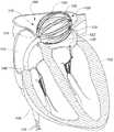
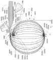
图1是示出根据一个示意性实施方式的经皮地放置在心脏的左心房中的医疗设备的心脏的剖面图。FIG. 1 is a cross-sectional view of a heart showing a medical device placed percutaneously in the left atrium of the heart according to an exemplary embodiment.
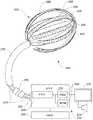
图2是根据一个示意性实施方式的医疗系统的部分示意图,包括控制单元、显示器和医疗设备,该医疗设备具有可扩展框架和与元件的组件。2 is a partial schematic view of a medical system including a control unit, a display, and a medical device with an expandable frame and assembly of elements, according to an illustrative embodiment.
图3A是根据另一个示例性实施方式的包括处于初始配置的多个长型构件的设备的一部分的侧视图。3A is a side view of a portion of an apparatus including a plurality of elongate members in an initial configuration according to another exemplary embodiment.
图3B是图3A的设备的长型构件中的具有代表性的一个的等距视图。Figure 3B is an isometric view of a representative one of the elongate members of the apparatus of Figure 3A.
图3C、3D、3E和3F是根据示例性实施方式的图3A中的设备的一部分在4个连续时间间隔下被定位在体腔内的各种侧视图。3C, 3D, 3E, and 3F are various side views of a portion of the device in FIG. 3A positioned within a body cavity at 4 consecutive time intervals, according to an exemplary embodiment.
图3G和3H是图3A的设备的长型构件的各种侧视图,其中长型构件被布置在第一散开阵列中。3G and 3H are various side views of elongate members of the apparatus of FIG. 3A , wherein the elongate members are arranged in a first spread out array.
图3I是图3A的设备的长型构件的截取的侧视图,其中长型构件被布置在第一散开阵列中。Fig. 31 is a cut-away side view of the elongate members of the apparatus of Fig. 3A, wherein the elongate members are arranged in a first spread out array.
图3J是图3A的设备的长型构件的部分截取的端视图,其中长型构件被布置在第一散开阵列中。Figure 3J is a partially cutaway end view of the elongate members of the apparatus of Figure 3A, wherein the elongate members are arranged in a first spread out array.
图3K和3L是图3A的设备的长型构件的各种侧视图,其中长型构件被布置在第二散开阵列中。3K and 3L are various side views of elongate members of the apparatus of FIG. 3A , wherein the elongate members are arranged in a second spread out array.
图3M是图3A的设备的长型构件的截取的侧视图,其中长型构件被布置在第二散开阵列中。Figure 3M is a cut-away side view of the elongate members of the apparatus of Figure 3A, wherein the elongate members are arranged in a second spread out array.
图3N是与处于第一散开阵列中的另一个长型构件的各种部分交叉的图3A的设备的长型构件的示意性代表图。3N is a schematic representation of an elongate member of the apparatus of FIG. 3A intersecting various portions of another elongate member in a first spread out array.
图3O是与处于第二散开阵列中的另一个长型构件的各种部分交叉的图3A的设备的长型构件的示意性代表图。3O is a schematic representation of an elongate member of the device of FIG. 3A intersecting various portions of another elongate member in a second spread out array.
具体实施方式Detailed ways
在下面的说明书中,阐明一些特定的细节一提供对本发明的各个实施方式的全面理解。然而,本领域技术人员将理解,本发明可在没有这些细节的情况下实现。在其他示例中,与射频(RF)烧蚀和电子控制(诸如,多路复用器)相关联的已知结构未被详细地示出或描述以避免不必要地混淆本发明的实施方式的描述。In the following description, specific details are set forth to provide a thorough understanding of various embodiments of the invention. However, it will be understood by those skilled in the art that the present invention may be practiced without these details. In other instances, known structures associated with radio frequency (RF) ablation and electronic controls, such as multiplexers, have not been shown or described in detail to avoid unnecessarily obscuring embodiments of the invention. describe.
词语“烧蚀(ablation)”应该被理解为表示对组织的某些属性的任何破坏。更常见地,破坏是电导率并且通过通过加热(可通过例如电阻或射频(RF)技术产生)实现。当使用术语“烧蚀”时,应包括其它属性(例如,机械或化学和其它破坏手段(诸如,光学))。The word "ablation" should be understood to mean any destruction of some property of tissue. More commonly, the destruction is conductive and is achieved by heating (which can be produced, for example, by resistive or radio frequency (RF) techniques). When the term "ablation" is used, other attributes (eg, mechanical or chemical and other means of destruction (such as optical)) shall be included.
词语“流体”应该被理解为表示可包含在体腔内或者可经由被定位为与体腔流体连通的一个或多个身体开口流入或流出或同时流入和流出体腔的任何流体。在心脏应用的情况中,诸如血液的流体将流入和流出心脏内的各种腔(例如,左心房和右心房)。The word "fluid" should be understood to mean any fluid that may be contained within a body cavity or that may flow into or out of, or both into and out of, a body cavity via one or more body openings positioned in fluid communication with the body cavity. In the case of cardiac applications, fluid such as blood will flow into and out of various chambers within the heart (eg, left and right atria).
词语“身体开口”应该被理解为自然出现的身体开口或通道或管腔;通过使用诸如包括但不限于机械、热、电、化学和曝光或照明技术实现器械或工具形成的身体开口或通道或管腔;通过对身体的创伤形成的身体开口或通道或管腔;或者一个或多个上面的各种组合。各个实施方式中可存在具有对应的开口、管腔或通道且被定位在身体开口内的各个元件(例如,导管鞘)。这些元件可提供供各个实施方式中采用的各种设备通过身体开口的通路。The term "body opening" shall be understood as a naturally occurring opening or passage or lumen of the body; a body opening or passage or passage or Lumen; a bodily opening or passage or lumen formed by trauma to the body; or various combinations of one or more of the above. In various embodiments there may be various elements (eg, introducer sheaths) having corresponding openings, lumens or channels and positioned within body openings. These elements may provide access through the body opening for various devices employed in various embodiments.
词语“组织”应该被理解为表示用于形成体腔内的表面、体腔内特征的表面或与定位为与体腔流体连通的身体开口相关联的特征的表面的任何组织。组织科包括包括限定体腔表面的表面的组织壁或薄膜的一部分或全部。就这一点而言,组织可形成腔的包围腔内流体的内表面。在心脏应用的情况中,组织可包括用于形成心脏内腔(诸如,左心房或右心房)的内部表面的组织。The word "tissue" should be understood to mean any tissue used to form a surface within a body cavity, a surface of a feature within a body cavity, or a surface of a feature associated with a body opening positioned in fluid communication with a body cavity. Histology includes a portion or all of a tissue wall or membrane including surfaces defining surfaces of body cavities. In this regard, the tissue may form the inner surface of the lumen surrounding fluid within the lumen. In the case of cardiac applications, the tissue may include tissue used to form the inner surface of a lumen of the heart, such as the left or right atrium.
本公开中的术语“传感器元件”应该被宽泛地解释成能够区别立体和组织、感测温度、产生热、烧蚀组织和测量组织表面的电活动、或它们的任何组合的任何设备。传感器元件可将一种形式的输入能量转换成另一种形式的输出能量。在没有限制的情况下,传感器元件可包括电极或感测设备。传感器元件可有若干部件构成,这些部件可以是分离的部件或可以是一体形成的。The term "sensor element" in this disclosure should be interpreted broadly as any device capable of distinguishing volume from tissue, sensing temperature, generating heat, ablating tissue, and measuring electrical activity at tissue surfaces, or any combination thereof. A sensor element converts one form of input energy into another form of output energy. Without limitation, sensor elements may include electrodes or sensing devices. The sensor element may be constructed of several components which may be separate components or which may be integrally formed.
贯穿本说明书的对“一个实施方式”或“实施方式”或“示例性实施方式”或“示出的实施方式”的提及表示关于实施方式描述的具体的特征、结构或特征包括在本发明的至少一个实施方式中。因此,短语“在一个实施方式中”或“在实施方式中”或“在示例性实施方式中”或“在这个示出的实施方式中”在整个说明书的各个位置的出现不一定全部指相同的实施方式。而且,具体的特征、机构或特征可在一个或多个实施方式中以任何合适的方式组合。Reference throughout this specification to "one embodiment" or "an embodiment" or "exemplary embodiment" or "the illustrated embodiment" means that a particular feature, structure, or characteristic described with respect to the embodiment is included in the present invention. In at least one embodiment of . Thus, appearances of the phrase "in one embodiment" or "in an embodiment" or "in the exemplary embodiment" or "in this illustrated embodiment" in various places throughout the specification are not necessarily all referring to the same implementation. Furthermore, the particular features, mechanisms or characteristics may be combined in any suitable manner in one or more embodiments.
在本文中描述了在血管内或经皮展开的医疗设备的各个实施方式。许多描述的设备可在递送或未扩展配置与展开或扩展或散开配置之间移动,在递送或未扩展配置中,设备的一部分的尺寸被设计为穿过通向体腔的身体开口,在展开或扩展或散开配置中,设备的一部分具有过大而不能穿过通向体腔的身体开口的尺寸。在一些示例性实施方式中,设备感测在流体(例如,血液)与形成体腔的内部表面的组织之间进行区别的特征(例如,对流冷却、介电常数、力)。这些感测的特征允许医疗系统对腔进行绘图(例如,通过使用进出腔的开口或空口的位置确定设备的该部分在体腔内的位置或定向(例如,姿势)或两者)。在一些示例性实施方式中,设备能够在体腔内以期望的图案烧蚀组织。在一些示例性实施方式中,设备能够感测表示烧蚀是否成功的特征(例如,电活动)。在一些示例性实施方式中,设备能够提供体腔内的组织的仿真(例如,电仿真)。电仿真可包括起搏。Various embodiments of medical devices deployed intravascularly or percutaneously are described herein. Many of the devices described are movable between a delivered or unexpanded configuration in which a portion of the device is In either the expanded or diffused configuration, a portion of the device is of a size that is too large to pass through the body opening to the body cavity. In some exemplary embodiments, the device senses a characteristic (eg, convective cooling, dielectric constant, force) that distinguishes between a fluid (eg, blood) and tissue forming an interior surface of a body cavity. These sensed features allow the medical system to map the cavity (eg, by using the location of the opening or cavity into and out of the cavity to determine the position or orientation (eg, posture) or both of that portion of the device within the body cavity). In some exemplary embodiments, a device is capable of ablating tissue in a desired pattern within a body lumen. In some exemplary embodiments, the device is capable of sensing a characteristic (eg, electrical activity) indicative of whether ablation was successful. In some exemplary embodiments, the device is capable of providing a simulation (eg, electrical simulation) of tissue within a body lumen. Electrical simulation may include pacing.
由根据各个实施方式的设备执行的绘图的实施例将是对通向肺静脉以及左心房的内部表面上的二尖瓣的各个身体开口的位置进行定位。在一些示例性实施方式中,绘图是至少基于通过区分流体和组织来定位这些身体开口。存在许多方式来区分组织与流体(诸如,血液)或区分组织与身体开口(在不存在流体的情况下)。通过实施例,三种方法可包括:Examples of mapping performed by a device according to various embodiments would be to locate the positions of the various body openings leading to the pulmonary veins and the mitral valve on the inner surface of the left atrium. In some exemplary embodiments, mapping is based at least on locating the body openings by distinguishing between fluid and tissue. There are many ways to distinguish tissue from fluid (such as blood) or tissue from a body opening (in the absence of fluid). By way of example, three methods may include:
1.使用由血液对加热的传感器元件的对流冷却。被定位为与形成心房的内部表面的组织相邻且跨越心房的孔口的传感器元件的稍微加热的布置将在横跨承载血液流的孔口的区域处更冷却。1. Using convective cooling of the heated sensor element by blood. A slightly heated arrangement of sensor elements positioned adjacent to the tissue forming the inner surface of the atrium and across the orifice of the atrium will be cooler at the region across the orifice carrying the blood flow.
2.使用介电常数的不同变化作为血液与组织之间的频率的函数。被定位在形成心房的内部表面的组织附近且跨越心房孔口的传感器元件组监控从1KHz至100KHz的介电常数的比率。这可用于确定这些传感器元件中的哪些不接近表示孔口位置的组织。2. Using the differential change in dielectric constant as a function of frequency between blood and tissue. A set of sensor elements positioned near the tissue forming the interior surface of the atrium and across the atrial orifice monitors the ratio of the dielectric constant from 1 KHz to 100 KHz. This can be used to determine which of these sensor elements are not in proximity to tissue representing the location of the orifice.
3.使用感测力的传感器元件(即,力传感器)。被定位在形成心房的内部表面的组织周围且跨越身体开口或心房孔口的一组力检测传感器元件可用于确定传感器元件中的哪些不与表示孔口位置的组织接触。3. Using sensor elements that sense force (ie force sensors). A set of force-detecting sensor elements positioned around the tissue forming the interior surface of the atrium and spanning the body opening or atrial orifice can be used to determine which of the sensor elements are not in contact with tissue indicative of the location of the orifice.
图1示出根据一个实施方式的用于调查或治疗身体器官例如心脏102的设备100。FIG. 1 shows a
设备100能够在血管内或经皮地插入心脏102的一部分,诸如心脏内的腔如左心房104。在该示例中,设备100是导管106的一部分,导管106经由下腔静脉108插入并从右心房112穿过右心房隔膜(transatrial septum)110中的身体开口。在其它实施方式中,也可以采用其它路径。
导管106包括长型柔性杆或轴构件,该构件的尺寸被适当地设置为经皮地或在血管内输送。导管106的各部分可以是易驾驭的。导管106可包括一个或多个管腔(未示出)。这些管腔可运载一个或多个通信装置或电源路径、或二者。例如,管腔可运载一个或多个电导体116。电导体116提供与设备100的电连接,这些电连接可从插入有设备100的患者外部进入。
如文中更加详细地描述,设备100包括结构或框架118,结构或框架118呈现出用于输送至左心房104的未扩展配置。框架118在输送至左心房104时被扩展(例如,在图1中被示出位于扩展或散开配置)以将多个传感器元件120(在图1中仅标出了三个)定位在由左心房104的组织122形成的内表面附近。在该示例性实施方式中,传感器元件120中的至少一部分被用于感测流体(例如,血液)或组织122或二者的物理特性,该物理特征可用于确定设备100的一部分在左心房104内或相对于左心房104的位置或定向或二者。例如,传感器元件120可用于确定肺静脉口(未示出)或二尖瓣126的位置。在该示例性实施方式中,传感器120的至少一部分可用于选择性地烧蚀组织122的部分。例如,这些元件中的一部分可用于在身体开口、孔口或肺静脉口周围烧蚀图案,例如以减小或消除心房颤动的发生。As described in greater detail herein,
图2示意性地示出根据一个示意性实施方式的包括设备200的系统。设备200包括多个柔性带204(图2中标出了三个)和多个传感器元件206(图2中标出了三个),这些传感器元件206被布置为形成能够在不需要机械扫描的情况下绘图、烧蚀或刺激体腔或管腔的内表面的二维或三维网格和阵列。这些柔性带204被布置在框架化结构208中,框架化结构208能够在未扩展配置和扩展或散开配置之间选择性地移动,扩展或散开配置可用于迫使柔性带204抵靠体腔内的组织表面或将柔性带定位在组织表面附近。柔性带204可形成柔性电路结构(即,又称为柔性印刷电路板(PCB)电路)的一部分。柔性带204可包括多个不同材料层。可扩展框架208可包括一个或多个弹性构件。可扩展框架208可包括一个或多个长型构件。该一个或多个长型构件中的每一个均可包括多个不同材料层。可扩展框架208可包括形状记忆材料,例如镍钛合金(Nitinol)。可扩展框架208可包括金属材料(例如不锈钢)或非金属材料(例如聚酰亚胺)或通过非限制性示例同时包括金属材料和非金属材料。根据各种因素,可产生将特殊材料结合至可扩展框架208的动机,这些因素包括未扩展配置和扩展或散开配置中的每一种的特殊需求、可扩展框架208在体腔中的所需的位置或定向(即,姿势)或二者、或对期望图案的成功烧蚀的要求。Fig. 2 schematically shows a system comprising a
可扩展框架208以及柔性带204可经由导管构件例如导管鞘引导器210输送和取回,在某些实施方式中,导管构件可具有约24Fr(French)或更小的直径,而在其它实施方式中,导管构件可具有约16Fr或更小的直径,虽然可采用能够经由具有更大或更小尺寸的导管片输送的设备。柔性带204可包括一个或多个材料层。柔性带204可包括一个或多个
设备200可与控制系统222通信、从控制系统222接收功率或受控制系统222控制。控制系统222可包括控制器224,控制器224具有一个或多个处理器226和储存指令的一个或多个储存媒介228,这些指令由处理器226执行以处理从设备200接收的信息或控制设备200的操作,例如激活所选的传感器元件206以烧蚀组织。控制器224可包括一个或多个控制器。控制系统222可包括烧蚀源230。烧蚀源230可例如向所选传感器元件206提供电流或功率、光或低温流体以引发烧蚀。烧蚀源可包括电流源或电功率源。控制系统222还可包括一个或多个用户接口或输入/输出(I/O)设备,例如一个或多个显示器232、扬声器234、键盘、鼠标、操纵杆、轨迹板、触摸屏或其它传感器以向用户(例如护理提供者诸如外科医生或技术人员)传输信息并从用户接受信息。例如,来自绘图处理的输出可显示在显示器232上。
在某些实施方式中,框架为医疗设备的用于辨别血液与组织的部分(例如,传感器元件的布置或阵列)提供扩展和收缩能力。用于感测参数或特性以区别流体(诸如血液)与组织的传感器元件可安装在框架上或以其它方式承载在框架上、或可以形成框架本身的整体部件。框架可以足够柔韧以在导管鞘内滑动以经皮地或在血管内展开。之前讨论的图2示出了这种框架的一个实施方式。In certain embodiments, the frame provides the ability to expand and contract the portion of the medical device that discriminates between blood and tissue (eg, the arrangement or array of sensor elements). Sensor elements for sensing parameters or properties to distinguish fluid (such as blood) from tissue may be mounted or otherwise carried on the frame, or may form an integral part of the frame itself. The frame can be flexible enough to slide within the introducer sheath for percutaneous or intravascular deployment. Figure 2, discussed previously, illustrates one embodiment of such a framework.
图3A是根据一个示例性实施方式的系统中采用的设备2500的一部分的侧视图。设备2500包括结构或框架2502,结构或框架2502包括长型构件2504a、2504b、2504c、2504d、2504e、2504f、2504g、2504h、以及2504i(统称为2504)的布置。其它实施方式还可采用不同数量的长型构件2504。多个长型构件2504物理地联接至轴构件2510,轴构件2510的尺寸被设置为穿过导管鞘2506运送长型构件2504。轴构件2510包括物理地联接至握柄部分2503的第一端部2510a和物理地联接至框架2502的第二端部2510b。在该示例性实施方式中,轴构件2510的第二端部2510b在靠近多个长型构件2504中的对应近端2507(仅标出一个)的一个或多个位置处联接至框架2502。在该示例性实施方式中,轴构件2510的第二端部2510b在靠近长型构件2504a的对应近端2507的位置处联接至框架2502。Figure 3A is a side view of a portion of a
图3B是长型构件2504中具有代表性的一个的等距视图。长型构件2504中的每一个均包括对应远端2505、对应近端2507和位于近端2507与远端2505之间的中部2509。各长型构件2504包括位于长型构件的对应近端2507和对应远端2509之间的对应长度2511。在该示例性实施方式中,多个长型构件2504中的每一个的对应长度2511均与长型构件2504中的另一个的对应长度2511不同。在某些实施方式中,长型构件2504中的两个或更多个可以具有基本相等的长度2511。在该实施方式中,长型构件2504中的每一个的对应长度2511(在图3A、3C、3D、3E、3F、3G、3H、3I、3J、3K、3L以及3M中未标出)均至少近似地等于或大于当设备2500的一部分处于展开配置时长型构件2504至少被定位于的体腔的内部组织表面的一部分的周长(未示出)。通过与其它所述实施方式相似的方法,传感器元件(未示出)可沿着多个长型构件2504的对应长度2511分布。由长型构件2504中的一个给定构件承载的传感器元件能够以展开配置分布在长型构件2504中的一个给定构件被定位在至少近端的体腔(同样未示出)的内部组织表面的基本圆周区域周围。FIG. 3B is an isometric view of a representative one of
再次参照图3B,长型构件2504中的每一个的中间部分2509包括一组两个相对的主面或表面2518,主面或表面2518由正面2518a和背面2518b构成。在该示例性实施方式中,两个相对的表面2518按照长型构件2504的厚度2517彼此间隔开。在该示意性示例中,各长型构件2504的中间部分2509还包括正面2518a和背面2518b中的至少一个(即,在该实施方式中为正面2518a)的一对侧边缘2520a、2520b(统称为2520),每对侧边缘2520的彼此相对的侧边缘横跨对应的长型构件2504的长度2511的至少一部分。在该示例性实施方式中,一对侧边缘2520限定长型构件2504的正面2518a的外周的一部分。对于长型构件2504,最短线2514(即,被示出为虚线)是可限定的。各最短线2514沿着长型构件2504的位于至少靠近长型构件2504的近端2507的第一位置与至少靠近长型构件2504的远端2505的第二位置之间的部分延伸。在这个实施方式中,每个最短线2514横跨长型构件2504的对应正面2518a延伸。为了清楚起见,最短线2514的一部分仅在图3B中显示在长型构件2504b的背面2518b上。如本文中所使用的,术语“最短线(geodesic)”应该被理解为表示在各种实施方式中所采用的长型构件的给定表面(例如,平坦表面、弯曲表面)上的两点之间延伸的最短线。在一些示例性实施方式中,最短线可跨越或桥接长型构件的表面的局部化开口或其它局部破裂,因为该最短线沿两个点之间的表面延伸。在一些示例性实施方式中,每个最短线2514与长型构件2504的对应主面2518的中线、中心线、纵轴线等等平行。Referring again to FIG. 3B, the
每个长型构件2504包括多个开口,多个开口包括第一开口2519a、第二开口2519b和第三开口2519c。在这个实施方式中,第一开口2519a、第二开口2519b和第三开口2519c中的每个提供穿过对应长型构件2504的中部2509的通道。第一开口2519a、第二开口2519b和第三开口2519c中的每个沿对应长型构件2504的长度2511彼此间隔开。Each
在这个实施方式中,每个长型构件2504遵从至少一个轴线。各个实施方式可包括长型构件2504,该长型构件2504是柔软的、柔性的或弹性的长型构件。各个实施方式可包括长型构件2504,该长型构件2504在绕多个不同地定向的轴线中的每个轴线弯曲时具有不同的弯曲刚度。In this embodiment, each
在这个示例性实施方式中,多个长型构件2504中的至少对应中部2509(在图3A中标出了一个)被预成型以在初始状态(即,低能状态)具有基本弯曲的轮廓。如图3A中最佳示出的,多个长型构件2504中的每个在初始/低能状态具有螺旋轮廓(例如,其自身向后弯曲的轮廓)。在一些示例性实施方式中,多个长型构件2504在初始/低能状态盘绕。在这个具体实施方式中,每个长型构件2504包括初始配置中的涡旋或涡卷轮廓。如图3A所示,在初始配置中,在初始堆叠阵列2516中,长型构件2504的对应中部2509中的每个相对于彼此以正面2518a朝背面2518b的方式布置。在这个示出的实施方式中,初始堆叠阵列2516是弓形的堆叠阵列。在这个所示的实施方式中,初始堆叠阵列2516是螺旋的堆叠阵列。在这个所示的实施方式中,在初始堆叠阵列2516中,长型构件2504中的每个沿其对应长度2511具有不同曲率。在这个示例性实施方式中,在初始堆叠阵列2516中,长型构件2504中的每个形成至少一个整圈。In this exemplary embodiment, at least corresponding middle portions 2509 (one labeled in FIG. 3A ) of plurality of
在各个示例性实施方式中,多个长型构件2504中的每个通过至少一个联接器与至少一个其它长型构件2504物理联接在一起。在这个所示的实施方式中,设备2500包括多个联接器2522,多个联接器2522包括近端联接器2522a、远端联接器2522c和至少一个中间联接器2522b。在各个示例性实施方式中,近端联接器2522a、远端联接器2522c和至少一个中间联接器2522b中的每个被布置为联接长型构件2504的至少第一个与长型构件2504的至少另一个。在这个所示的实施方式中,近端联接器2522a形成可枢转关节的一部分并且包括枢轴构件2523。在这个实施方式中,枢轴构件2523为销形式,销的尺寸被设计为接纳在各自的第一开口2519a中(即,在图3B中最佳可见),第一开口2519a设置在每个长型构件2504内。多个长型构件2504中的每个被配置为绕与枢轴构件2523相关联的枢轴线转动、绕转、枢转或旋转。在其它实施方式中,可采用其它形式的枢转关节。例如,可采用挠曲关节。挠曲关节可至少部分地通过在长型构件2504中的至少一个中提供扭曲部来提供。In various exemplary embodiments, each of plurality of
在这个示例性实施方式中,远端联接器2522c包括柔性线2540c的第一部分2541a,第一部分2541a的大小被设计为且被布置为接纳在每个长型构件2504的对应第三开口2519c(即,在图3B中最佳可见)内,由此将每个长型构件2504物理联接在一起。在这个示例性实施方式中,柔性线2540c的至少第二部分2541b形成长型构件操纵器2550的控制构件的一部分,第二部分2541b的一部分可沿穿过导管鞘2506的路径延伸。长型构件操纵器2550可包括各种致动器(未示出),致动器操作地联接至各个控制构件以经由这些控制构件传递力。合适的致动器可包括有源或无源的致动器。合适的致动器可包括由护理提供者操纵以使力经由控制构件传递的握柄、旋钮、杠杆、等等(未示出)。在一些实施方式中,分离的控制构件联接至柔性线2540c的第一部分2541a。在这个示例性实施方式中,中间联接器2522b包括柔性线2540b,柔性线2540b的大小被设计且被布置为接纳在每个长型构件2504的对应第二开口2519b内(即,在图3B中最佳可见),由此将每个长型构件物理联接在一起。各种结、套圈、套管等等可被采用以阻止被定位在第二和第三开口2519b、2519c的至少一个中的柔性线从开口脱离。注意,在一些实施方式中可采用替代或附加的联接器2522。注意联接器2522的数量不限于3个并且可包括小于或大于3的数量。在一些示例性实施方式中,仅采用近端联接器2522a和远端联接器2522c。在各个示例性实施方式中,多个联接器2522均可联接长型构件2504的一些或全部。In this exemplary embodiment,
在这个示例性实施方式中,图3C、3D、3E和3F是根据示例性实施方式的设备2500的在4个连续的时间间隔处被定位在体腔内的部分的各个侧视图。在这个所示的实施方式中,体腔是心脏2560的左心房2562,为了清楚起见,左心房2562以截面示出。如图3C所示,长型构件2504(仅标出一个)被布置为在堆叠阵列2515中以一个正面2518a朝向另一个的背面2518b(在图3C中未标出),其中堆叠阵列2515的大小被设计为当设备2500的一部分处于被称为第一或未扩展配置的递送配置中时通过身体开口2564(即,经由图3C中以截面示出的导管鞘2506的管腔2506c)被递送。在这个示例性实施方式中,身体开口2564通向左心房2562,左心房2564包括被开口2564的孔口2564a中断的内部组织表面2562a。在这个示例性实施方式中,长型构件2504的对应中部2509(仅标出一个)被布置在堆叠阵列2515中,使得每个长型构件2504以递送配置前进并使远端2505首先进入左心房2504。为了清楚起见,与中间联接器2522b和远端联接器2522c的对应联接器相关联的柔性线2540b和2540c在图3C、3D、3E、3F、3G、3H、3I、3K、3L、3N和3O未示出。In this exemplary embodiment, Figures 3C, 3D, 3E and 3F are respective side views of portions of
如图3C所示,每个长型构件2504以第一/未扩展配置相对于彼此连续地被布置在堆叠阵列2515中。在这个实施方式中,堆叠阵列2515中的长型构件2504的布置是按顺序的,其中每个长型构件2504沿由箭头2529所表示的第一方向(即,堆叠方向)相对于彼此连续地被布置。可理解,第一方向2529不需要是竖直或“上下”方向,还可包括其他定向。例如在一些实施方式中,沿第一方向2529彼此连续相邻的长型构件2504可在一个或多个其它方向相对于彼此成阶梯式。因此,该组成型构件2504可以适于长方体的非阶梯式堆叠布置被布置,或者可以例如适于非长方体的阶梯式堆叠布置被布置。As shown in FIG. 3C, each
在这个所示的实施方式中,表面2518相对于彼此连续地被布置在堆叠阵列2515中。在这个实施方式中,长型构件2504被连续布置在阵列式布置中,该阵列式布置的尺寸被设计为通过导管鞘2506的管腔2506c被递送,每个长型构件2504被定位在阵列式布置中,使得长型构件2504的正面2518a朝向阵列式布置中的另一个长型构件2504的背面2518b,或者长型构件2504的背面2518b朝向阵列式布置中的另一个长型构件2504的正面2518a,或者两者。在这个示例性实施方式中,长型构件2504的正面2518a和背面2518b在堆叠阵列2515中交错。In this illustrated embodiment, the surfaces 2518 are arranged in a
在各个实施方式中,每个长型构件2504具有至少一个表面,该至少一个表面与其它长型构件2504的至少一个表面具有共同的特征,或对应于其它长型构件2504的至少一个表面,并且长型构件2504被布置在阵列式布置中或堆叠阵列中使得长型构件2504的至少一个表面沿堆叠阵列2515第一方向被连续地布置。在这个方面,注意,堆叠布置不要求单独的长型构件2504实际上彼此抵靠。在堆叠布置的许多示例中,长型构件或其一部分可例如在交错布置的实施方式中例如通过空间与连续相邻的长型构件分离。在这些实施中,当设备2500的一部分处于示例性展开配置(也称为体腔内的第三或扩展或散开配置(例如,如图3E和图3F所示)、在此应用中可替换地称为散开配置、扩展配置或扩展散开配置)时,每个至少一个表面为可被定位成与体腔内的组织表面相邻的第一表面。在这些各种示例性实施方式的一些中,当设备2500的一部分移动到体腔内的第三/扩展或散开配置(例如如图3E和3F所示)时,每个至少一个表面是可被定位成面向或接触体腔内的组织表面的第一表面。在这些各种示例性实施方式的一些中,每个至少一个表面是包括或支撑(即,直接或间接)一个或多个传感器元件的第一表面。在这些各种实施方式中的一些中,当设备2500的一部分在体腔内处于第三/扩展或散开配置(例如,如图3E和3F所示)时,每个至少一个表面是包括或支撑(即,直接或间接)可被定位成与组织表面相邻的一个或多个传感器元件(例如,电极)的第一表面。在这些各种实施方式的一些中,每个至少一个表面是包括或支撑(即,直接或间接)柔性电路结构的第一表面。在这些各种实施方式中的一些中,当设备2500的一部分处于体腔内的第三/扩展或展开配置(例如,如图3E和3F所示)时,每个至少一个表面是可被定位成背对体腔内的组织表面的第二表面。在这些各种实施方式的一些中,当设备2500的一部分处于第三/扩展或散开配置(例如,如图3E和3F所示)时,每个至少一个表面被布置为背对长型构件2504在有角度间隔时所围绕的轴线。In various embodiments, each
在一些实施方式中,长型构件2504被布置为彼此连续相邻。在一些实施方式中,堆叠阵列2515中的多个连续长型构件2504对中的两个长型构件2504之间可存在部分或完整的间隔或间隙。在堆叠阵列2515中,每个连续长型构件2504对中的两个长型构件2504之间可存的基本一致的间隔或尺寸变化的间隔。在一些示例性实施方式中,在堆叠阵列2515中,可在多个连续的长型构件2504对中的两个长型构件2504之间设置有各种其它元件。例如,各个传感器元件可被定位在堆叠布置2515中的多个连续长型构件2504对中的两个长型构件2504之间。在一些实施方式中,至少三个长型构件2504沿第一方向2529线性地布置在阵列式布置中。在一些实施方式中,至少三个长型构件2504沿第一方向2529相对于彼此连续布置在堆叠阵列2515中。In some embodiments,
长型构件2504可以是基本平坦的构件或者可在递送配置中具有某个初始曲率。表面2518a和2518b中的至少一个不需要是平坦的表面。在这个示例性实施方式中,长型构件2504具有允许它们连续堆叠在堆叠阵列2515中的形状。
有利地,尤其当长型构件被允许在弯曲期间相对于彼此滑动时,这个实施方式中的带状长型构件2504进一步允许绕与堆叠阵列2515中的长型构件2504的第一或堆叠方向2529垂直布置的弯曲轴线具有减少的弯曲刚度。尤其当导管鞘2506沿曲折路径延伸至体腔时,减少的弯曲刚度可方便堆叠阵列2515通过导管鞘2506递送。许多传统的篮式导管系统中的构件以典型不利地限制构件之间的滑动的方式被联接一起,限制构件之间的滑动可不利地影响通过导管鞘的递送。Advantageously, the strip-like
长型构件2504可由各种材料构造,这些材料包括但不限于各种金属和非金属复合物、复合材料诸如碳纤维、或具有纤维玻璃或镍钛合金背衬的柔性PCB衬底。长型构件2504可包括一个或多个材料层。长型构件2504可形成各种感测和烧蚀传感器元件的整体部件。当传感器元件形成框架2502的整体部件时,在框架中使用的各种材料组分可能需要各种机械和电气属性。
在这个示例性实施方式中,初始堆叠阵列2516中的多个长型构件2504的对应中部2509已经从图3A所示的它们的初始或低能状态被加压至较高的能量状态。在这个示例性实施方式中,初始堆叠阵列2516中的长型构件2504已经被加压至较高能量状态,该较高能量状态适于使长型构件2504充分变直以便在图3C所示的递送配置期间通过导管鞘2506递送。在这个示例性实施方式中,通过在将导管鞘2506插入体内之前使初始堆叠阵列2516收缩至导管鞘2506内,初始堆叠阵列2516被加压至较高能量状态。在一些示例性实施方式中,通过将初始堆叠阵列2516展开并且将初始堆叠阵列插入导管鞘2506,初始堆叠阵列2516被加压至较高能量状态。在一些示例性实施方式中,在使用点处,长型构件2504的布置从图3A的初始配置被重新配置成图3C所示的递送配置。在一些示例性实施方式中,在制造、组装或分配地点,长型构件2504的布置从图3A的初始配置被重新配置成图3C的递送配置。在各个实施方式中,可采用包括各个引导件或操纵器的各个设备以将长型构件2504的布置从图3A的初始配置重新配置成图3C所示的递送配置。在这些各种实施方式的一些中,这些设备形成设备2500的一部分。在这些各种实施方式的一些中,这些设备位于设备2500的外部。优选地,较高能量状态被控制以在递送期间不对设备2500或导管鞘2506造成损坏。In this exemplary embodiment, corresponding
在这个示例性实施方式中,潜在的能量通过较高能量状态被传送到堆叠阵列2515中的多个长型构件2504中,当从导管鞘2506的约束中释放时,潜在的能量足以使长型构件2504的布置大致返回到它们的初始能量状态。In this exemplary embodiment, latent energy is delivered to the plurality of
在这个示例性实施方式中,管腔2506c被定位在导管鞘2506的第一端2506a与导管鞘2506的第二端2506b之间。在一些实施方式中,导管鞘2506可包括多个管腔。在这个实施方式中,每个长型构件2504被布置在一种布置中,该布置的尺寸被设计为在递送配置中从第一端2506a朝向第二端2506b通过导管鞘的管腔2506c递送。在这个示例性实施方式中,每个长型构件2504被布置为在递送配置中促使远端2505首先从导管鞘2506的管腔2506c出来。在一些实施方式中,导管鞘2506的至少一部分是易驾驭的。In this exemplary embodiment,
图3D示出了设备2500的包括多个长型构件2504的部分,多个长型构件2504在左心房2562内处于展开配置,也称为第二或弯曲配置。在这个示例性实施方式中,每个长型构件2504(仅标出了一个)绕对应的弯曲轴线2531(仅示出了一个)弯曲成弓形的堆叠阵列2532。在一些实施方式中,多个长型构件2504的每个的一部分绕对应的弯曲轴线2531弯曲以具有变化的曲率。每个弯曲轴线2531沿一个方向延伸,该方向具有被横向地定向成长型构件2504的对应长度2511(图3D中未标出)的方向分量。在这个示例性实施方式中,弓形的堆叠阵列2532中的每个长型构件2504绕对应的弯曲轴线2531卷绕成卷绕的堆叠阵列。在这个示例性实施方式中,每个长型构件2504被弯曲以在左心房2562内具有涡形轮廓。在这个示例性实施方式中,每个长型构件被弯曲以在左心房内具有曲率,该曲率沿长型构件2504的对应长度2511改变至少一次。当被定位在第二/弯曲配置中时,每个长型构件2504的对应中部2509(仅标出了一个)的正面2518a的第一部分2521a被定位为与涡形框架2502中的正面2518a的第二部分2512b在直径上相对。当被定位在第二/弯曲配置中时,长型构件2504的卷绕布置的尺寸被设计为太大以不能通过导管鞘2506的管腔2506c递送。FIG. 3D shows a portion of
在这个示出的实施方式中,当中部2509被推进体腔诸如左心房内时,多个长型构件2504的对应中部2509已经被预成型为自动弯曲。当对应的中部2509被推进左心房2562内时,它们摆脱了导管鞘2506的约束并且返回到它们的低能状态(即,它们的初始卷绕配置)。在这个示例性实施方式中,当设备2500的的一部分在第一/扩展配置与第二/弯曲配置之间移动时,多个长型构件2504的对应远端2505在左心房2562内沿卷绕路径(例如,自身向后弯的路径)移动。在该示例性实施方式中,卷绕路径在左心房2562内至少形成一整圈。在这个示例性实施方式中,卷绕距离的至少一部分可沿涡形路径延伸。在这个示例性实施方式中,第二/弯曲配置中的长型构件2504被布置在弓形的堆叠阵列2532中,弓形的堆叠阵列2532类似于长型构件2504被布置在它们的初始状态(即,如图3A所示)的初始堆叠阵列2516。在这个示例性实施方式中,轴构件2510和框架2502在第二/弯曲配置中具有大体涡形或希腊字母rho(ρ)形的投影轮廓,该字母在字母的环将与字母的尾部相交的点处开放。In this illustrated embodiment, the corresponding
在这个示例性实施方式中,多个长型构件2504被预成型以使堆叠阵列2515在被推进到左心房2562内时自动卷绕,从而可有利地减少左心房2562内堆叠布置2515与内部组织表面2562a之间的物理互作用,因为当长型构件2504被推进左心房2562内时长型构件2504的对应远端2505(仅标出了一个)自动弯曲或卷曲远离内部组织表面2562a。与内部组织表面2562a的接触和其它物理互作用的减少可减少在此定位期间左心房2562内的各个组织结构所遭受的损伤的发生或严重性。在这个所示的实施方式中,弓形的堆叠阵列2532的尺寸被优选地设计为可定位在左心房2562内以与左心房2562的内部组织表面2562a具有最大、最小量的接触。这个所示的实施方式可通过采用使长型构件在被推进体腔内时弯曲的弯曲设备,进一步减少对左心房2562内的各个组织结构的潜在损伤。许多弯曲设备可在长型构件的各个部分在体腔内弯曲期间将能量传送到长型构件内。弯曲设备或长型构件自身的故障可释放至少一部分潜在能量并且可能损伤体腔内的各个组织结构。不同于这些实施方式,弓形的堆叠阵列2532中的长型构件2504具有小的潜在能量,因为它们基本已经处于它们的低能状态。In this exemplary embodiment, plurality of
图3E示出了设备2500的在左心房2562中处于展开配置也称为第三或扩展或散开配置的部分。在这个所示的实施方式中,长型构件2504(仅标出了一个)从图3D所示的第二/弯曲配置移动至图3E所示的第三/扩展或散开配置。在这个所示的实施方式中,图3E所示的弓形的堆叠阵列2515中的长型构件2504的至少一些在左心房2562中被重新定位。在这个示例性实施方式中,多个长型构件2504被移动以在左心房2562内将至少一些长型构件2504的各个部分彼此间隔开。在这个所示的实施方式中,多个长型构件2504绕一个或多个散开轴线(在图3E中未示出)相对于彼此散开成第一散开阵列2570。FIG. 3E shows a portion of
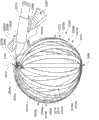
如图3G、3H、3I和3J所示,至少一个长型构件2504在靠近第一轴线2535的位置处以X配置与另一个长型构件2504交叉。如本文和权利要求所使用的,第一长型构件在一个或多个位置的每个处以X配置与第二长型构件交叉表示,第一长型构件的对应部分在一个或多个位置的每个位置处以类似于字母“X”(在交叉部分、位置或点处从一个长型构件垂直观看或投影)的交叉配置与第二长型构件的对应部分交叉。可理解,交叉的第一和第二长型构件的各个对之间的交叉角可在给定的实施方式中或在不同的实施方式之间改变。如图3G、3H、3I和3J所示,多个长型构件2504绕第一轴线2535散开。在这个示例性实施方式中,当设备的一部分处于第三/扩展或散开配置时,第一轴线2535沿至少一些长型构件2504的每个的对应长度2511穿过的多个间隔的位置。在这个示例性实施方式中,至少一些长型构件2504的每个的对应中部2509相对于彼此绕第一轴线2535有角度地间隔开。在这个示出的实施方式中,多个长型构件2504的至少一些的每个包括弯曲部分2509a(即,在图3G、3H和3I中示出),弯曲部分2509a被布置为沿弯曲路径的至少一部分延伸,该弯曲路径在第三/扩展或散开配置中沿第一轴线2535的对应至少两个间隔开的位置中的每个处与第一轴线2535相交。在各个实施方式中,长型构件2504的弯曲部分2509a可完全沿或至少部分地沿对应的弯曲路径延伸,该弯曲路径在第三/扩展或散开配置中在沿第一轴线2535的至少两个间隔开的位置中的每个处与第一轴线2535相交。在各个实施方式中,弯曲路径是弓形路径。在各个实施方式中,弯曲路径的至少沿弯曲部分2509a延伸的部分是弓形的。在这个实施方式中,至少第一长型构件2504在沿第一轴线2535的对应至少两个间隔开的位置中的至少一个中的每个处以X配置与第二长型构件2504交叉,第一轴线2535在第三/扩展或散开配置中与沿第二长型构件2504的弯曲部分2509a延伸的对应弯曲路径的至少一部分相交。在这个示例性实施方式中,第一轴线2535被显示为单个轴线。可理解,第一轴线2535在各个实施方式中可包括一个或多个轴线。如图3I所示,在这个示例性实施方式中,在第三/扩展或散开配置中,框架2505的一部分与第一轴线2535径向间隔第一尺寸2580a。在各个示例性实施方式中,框架2502的与第一轴线2535径向间隔第一尺寸2580a的部分可包括至少一个长型构件2504的对应弯曲部分2509a。As shown in FIGS. 3G , 3H, 3I, and 3J, at least one
在这个示出的实施方式中,轴构件2510的第二端部2510b在框架2502的各个位置处未物理联接或连接至框架,在第三/扩展或散开配置中,沿第一轴线2535观看,框架2502的这些位置绕第一轴线2535对称地定位。然而在这个示例性实施方式中,轴构件2510的第二端部2510b在框架2502上的一个或多个位置处物理地联接或连接至框架2502,第二端部所联接的结构上的一个或多个位置的每个被定位在与第一轴线2535重合的至少一个空间平面(未示出)的一侧。在这个示例性实施方式中,轴构件2510的第二端部2510b物理地联接或连接至少接近框架2502中的多个长型构件2504的近端2507。在这个示出的实施方式中,框架2502与轴构件2510的第二端部2510b之间的定位至少部分地通过多个长型构件2504在左心房2562内的卷绕形成。在这个示例性实施方式中,轴构件2510被定位为避免在第三/扩展或散开配置中与第一轴线2535相交。在这个示例性实施方式中,轴构件2510被定位为避免在第三/扩展或散开配置中第二端部2510b与第一轴线2535相交。在一些示例性实施方式中,多个长型构件2504的至少一些的每个可在第三/扩展或散开配置中从轴构件2510的第二端部2510b大体切向地延伸。在这个示例性实施方式中,轴构件2510和框架2502在第三/扩展或散开配置中具有希腊字母rho(ρ)的形状的投影轮廓,并且没有或有由所表示的字母的环部分限定的开口。如上所提到的,希腊字母ρ可表达成在字母的环将与字母尾部相交(如果闭合或未开放)的点处开放。In this illustrated embodiment, the
当设备2500的部分移动到第三/扩展或展开配置中时,多个长型构件2504可以各种方式移动。在这个示例性实施方式中,与弓形的堆叠布置2532中的顺序布置的长型构件2504中的第二组“奇”长型构件2504(即,长型构件2504c、2504e、2504g和2504i)散开所沿的方向相比,弓形的堆叠布置2532中的顺序布置的长型构件2504中的第一组“偶”长型构件2504(即,长型构件2504b、2504d、2504f和2504h)绕轴线2535沿相反的角度方向散开。在这个上下文中,词语“偶”和“奇”指弓形的堆叠阵列2532中的对应长型构件2504的位置。在这个示例性实施方式中,弓形的堆叠阵列中“偶”组中的长型构件2504与“奇”组中的长型构件2504交错。在这个示例性实施方式中,各种散开机构(未示出)可被采用以将多个长型构件2504移动至第四/扩展或散开配置中。在一些示例性实施方式中,各个散开机构(未示出)可被采用以在至少一些长型构件2504处部分或全部地散开。例如,各种元件(例如,柔性线)可被部分地联接至至少一些长型构件2504以施加适于使多个长型构件2504相对于彼此散开的力。在一些示例性实施方式中,至少一些长型构件2504的每个的至少一部分被预成型以使至少一些长型构件2504相对于彼此(即,至少部分地)自动散开。当长型构件从导管鞘2506被推动充足的量时,自动散开可发生。至少一些长型构件2504的每个的预成型的至少一部分可包括弯曲部分或扭曲部分、或者两者。When portions of
图3G和图3H是在第三/扩展或散开配置期间布置在第一散开阵列2570中的长型构件2504的立体等距视图,每个视图示出了第一散开阵列2570的两个相反侧之一。长型构件2504a和该组“奇”长型构件2504c、2504e、2504g和2504i在图3G中被标出而长型构件2504a和该组“偶”长型构件2504b、2504d、2504f和2504h在图3H中被标出。在这个示例性实施方式中,在设备2500的一部分处于第三/扩展或散开配置时,每个长型构件2504的正面2518a的第一部分2521a(仅标出了一个)的每个被定位为与正面2518a(即,如在图3G与图3H之间的比较)的第二部分2512b(仅标出了一个)在直径上相反。在这个示例性实施方式中,当设备2500的一部分移动到第三/扩展或散开配置中时,与弓形的堆叠阵列2532中的另一长型构件2504的背面2518b(在图3E中未标出)面对的弓形的堆叠阵列2532中的至少一些长型构件2504的每个的正面2518a(在图3E中未标出)的一部分在左心房中被重新定位,从而在左心房2562内第一散开阵列2570中的至少一些长型构件2504的每个的正面的一部分直接面向内部组织表面2562a的一部分。3G and 3H are perspective isometric views of
在这个实施方式中,框架2502是包括近端部分2502a和远端部分2502b的结构,近端部分2502a和远端部分2502b中的每个由多个长型构件2504中的每个长型构件2504的对应部分组成。如在图3C中最佳示出的,当设备2500的该部分处于第一/未扩展配置时,框架2502被布置为将远端部分2502b首先推进左心房2562内。如图3G和图3H的每个最佳可见,当设备的该部分处于第三/扩展或散开配置时,框架2502的近端部分2502a形成第一圆顶形状2508a并且框架2502的远端部分2502b形成第二圆顶部分2508b。在这个示例性实施方式中,第一圆顶形状2508a具有对应的顶点2512a(即,在图3H中示出)并且第二圆顶形状2508b具有对应的顶点2512b(即,在图3G中示出)。在这个示例性实施方式中,当设备2500的该部分处于第三/扩展或散开配置时,与框架2502的远端部分2502b相关联的顶点2512b被定位为比与框架2502的近端部分2502a相关联的顶点2512a更接近开口2564的孔口2564a。在一些示例性实施方式中,当设备2500的该部分处于第三/扩展或散开配置时,与框架2502的远端部分2502b相关联的顶点2512b被定位在孔口2564a和与框架2502的近端部分2502a相关联的顶点2512a之间。在一些示例性实施方式中,当设备2500的该部分处于第三/扩展或散开配置时,与框架2502的远端部分2502b相关联的顶点2512b被定位在导管鞘2506的第二端2506b和于框架2502的近端部分2502a相关联的顶点2512a之间。在一些示例性实施方式中,当设备2500的该部分处于第三/扩展或散开配置时,与框架2502的远端部分2512a相关联的顶点2512b被定位在轴构件2510的一部分和与框架2502的近端部分2502a相关联的顶点2512a之间。In this embodiment, the
在各个示例性实施方式中,第一和第二圆顶形状2508a、2508b中的任何一个不需要为大体半球形。例如,第一圆顶形状2508a和第二圆顶形状2508b中的至少一个可在第一空间平面中具有第一曲率半径并在与第一空间平面相交的第二空间平面中具有第二曲率半径,第二曲率半径的大小不同于第一曲率半径的大小。在这个示例性实施方式中,当设备2500的该部分处于第三/扩展或展开配置时,多个长型构件2504的至少一些的每个长型构件2504在框架2502的远端部分2502a、2502b之间的位置处与多个长型构件2504的至少一个其它长型构件2504交叉。在这个示例性实施方式中,在第三/扩展或展开配置中,框架2502的近端和远端部分2502a、2502b被布置成蛤壳配置。In various exemplary embodiments, either of the first and
图3I是图3G中示出的第一散开阵列2570的详细等距视图的截面侧视图。图3G、3H、3I和3J的每个进一步示出了轴构件2510的对应部分和导管鞘2506以及孔口2564a中断左心房2563的内部组织表面2562a(在图3H中未标出)的部分。在这个示出的实施方式中,在如图3I中的长型构件2504a最佳示例的第三/扩展或散开配置中,每个长型构件2504包括涡卷形状轮廓。在这个示出的实施方式中,长型构件2504的各个部分散开,从而多个长型构件2504中的每个的第二开口2519b(在图3G、3H、3I和3J的每个中仅标出了一个)和第三开口2519c(在图3G、3H、3I和3J的每个中仅标出了一个)不与另一个长型构件2504中的第二开口2519b和第三开口2519c中的对应的一个开口对齐。为了清楚起见,在图3G、3H和3I的每个中未示出柔性线2540b中的每个和柔性线2540c的第一部分2541a,其中第一部分2541a形成中间联接器2522b和远端联接器2522c的对应联接器的一部分且被布置为穿过每个长型构件2504中的第二开口2519b和第三开口2519c的对应开口。Figure 31 is a cross-sectional side view of the detailed isometric view of the first fan-out
图3J是第一散开阵列2570的部分剖面端视图,其示出了长型构件2504的对应远端2505(标出了两个)。多个长型构件2504在图3J中被部分地剖视以最佳地示出长型构件2504的对应远端2505(标出了两个)。图3J示出了柔性线2540c的第一部分2541a,柔性线2540c追随通过“偶”长型构件2504b、2504d、2504f和2504h和“奇”长型构件2504c、2504e、2504g和2504i中的交替长型构件的第三开口2519c(仅标出了一个)的弯曲、曲折或蜿蜒的路径。柔性线2540b(未示出)可追随通过第二开口2519b(即,仅标出了一个)的类似路径。柔性线2540c的第二部2541b也在图3J中示出。FIG. 3J is a partial cross-sectional end view of first spread out
如在图3G和3H中最佳示出,长型构件2504g的对应最短线2514与至少一个其它长型构件2504(即,这个示例性情况中为长型构件2504i)在沿该至少一个其它长型构件2504的对应长度2511(未标出)的各个位置处交叉(如法向于上面在第三/扩展或散开配置中定位有各个对应位置的至少一个其它长型构件2504的正面2518a的对应部分看过去)。为了清楚的说明,多个长型构件2504的对应最短线2514未在图3G和3H中示出。As best shown in FIGS. 3G and 3H , the corresponding
图3N示意性地示出了第一散开阵列2570包括第二长型构件(即,长型构件2504i)的部分,第一长型构件(即,长型构件2504g)的各个部分在第三/扩展或散开配置中的各个位置处以X配置与第二长型构件2504i交叉。为了清楚起见,长型构件2504i和2504g中的每个以“平坦的”状态被显示,并且可理解,这些长型构件包括如图3G和3H中作为示例的对应弓形轮廓。第一长型构件2504g的对应最短线2514在多个间隔开的位置(即,由图3N中“X”所表示的每个位置)处与第二长型构件2504i的对应最短线2514交叉,所述多个间隔开的位置包括第一位置2544c,第一位置2544c在第三/扩展或散开配置中沿第二长型构件2504i的相对最短线2514比两个其它位置2544a和2544b更接近第二长型构件2504的对应远端2505。可理解,在图3N中,交叉位置2544a、2544b和2544c中的每个位于第二长型构件2504i的正面2518上并且与第一长型构件2504g重叠。在这个示出的实施方式中,第一位置2544c位于近端联接器2522a的位置与第二长型构件2504i的对应远端2505之间。在这个示出的实施方式中,第一位置2544c沿第二长型构件2504i的对应长度2511被定位在远端联接器2522c(即,在图3N中其位置由第三开口2519c表示的柔性线2540c的第一部分2541a)和中间联接器2522b(即,在图3N中其位置由第二开口2519b表示的柔性线2540b)的对应位置之间。在这个示例性实施方式中,第一位置2544c沿第二长型构件2504i的对应长度2511被定位为相对于中间联接器2522b和近端联接器2522a中的每个的对应位置更接近第二长型构件2504i的对应远端2505。在这个示例性的实施方式中,第一位置2544c与第二长型构件2504i的对应远端2505间隔开。在这个示例性实施方式中,第一长型构件2504g在位置2544b和2544c的每个处以X配置与第二长型构件交叉。FIG. 3N schematically illustrates that first spread out
在这个示例性实施方式中,当设备2500的包括长型构件2504的部分移动到第三/扩展或散开配置中时,设备2500的该部分在体腔诸如左心房2562内的附加操纵被启动。典型地,当布置在弓形的堆叠阵列2532中的长型构件2504被重新定位成散开阵列(即,第一示例性实施方式中的第一散开阵列2570)时,长型构件2504优选地被布置为一般远离左心房2562内的各个组织表面以避免可能阻碍重新定位的障碍并且避免使组织表面遭受损伤。参考图3E,当设备2500的该部分处于第三/扩展或散开配置时,一些长型构件2504中的每个的各个部分被定位为远离左心房2562内的内部组织表面2562a。如在图3G与图3H之间的比较,当设备2500的该设备处于第三/扩展或散开配置时,第一散开阵列2570中的至少一些长型构件2504中的每个的第一部分2521a(仅标出了一个)和第二部分2521b(仅标出了一个)绕第一轴线2535有角度地被布置。在这个示出的实施方式中,至少一些长型构件2504还在第三/扩展或散开配置中被进一步操纵以改变第一轴线2535与多个长型构件2504的正面2518a的第一部分2512a和第二部分2512b的至少一个之间的径向间隔。如图3F所示,至少一些长型构件2504(仅标出了一个)在第三/扩展或散开配置中被进一步操纵以形成第二散开阵列2572。在这个示例性实施方式中,至少一些长型构件2504被进一步操纵以增加第一轴线2535与多个长型构件2504的正面2518a的第一部分2521a(图3F中未标出)和第二部分2521b(图3F中未标出)的至少一个之间的径向距离。在这个示例性实施方式,至少一些长型构件2504被进一步操纵以增加第一尺寸2580a(在图3F中未标出)。In this exemplary embodiment, when the portion of
至少一些长型构件2504的进一步操纵可由于各种原因被激发。例如,至少一些长型构件2504可被进一步操纵以调整由长型构件2504承载的各个传感器元件与体腔内的组织表面之间的定位。当设备2500的该部分被移动至第三/扩展或散开配置时,至少一些长型构件2504可被进一步操纵以建立与体腔诸如左心房2562的组织表面的相符性。在一些示例性实施方式中,当设备2500的该部分移动至第三/扩展或散开配置时,体腔诸如左心房2562的组织表面被进一步操纵以符合多个长型构件2504的形状。在一些示例性实施方式中,当长型构件2500的一部分移动至第三/扩展或散开配置时,长型构件2504的该部分和体腔诸如左心房2562内的组织表面均被进一步操纵以建立多个长型构件2504与组织表面的一部分之间的相符性。在这个示例性实施方式中,当长型构件2504被进一步操纵成第二散开阵列2572时,轴构件2510和框架2502具有希腊字母ρ形状或涡形的投影轮廓。Further manipulation of at least some
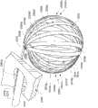
图3K和3L是布置在图3F所示的第二散开阵列2572中的长型构件2504的立体详细等距视图,每个视图示出了第二散开阵列2572的两个相反侧的一个。在一些示例性实施方式中,当设备的该部分移动至第三/扩展或散开配置时,框架2502的近端和远端部分2502a、2502b被进一步操纵。在一些示例性实施方式中,当框架2502的近端和远端部分2502a、2502b的对应圆顶形状结构(即,第一和第二圆顶形状2508a、2508b)处于第三/扩展或散开配置时,该结构被物理联接在一起以相对于彼此枢转。在这个示例性实施方式中,框架2502的近端和远端部分2502a、2502b的对应圆顶形状结构(即,第一和第二圆顶形状2508a、2508b)可相对于彼此绕框架2502中减少的弯曲刚度的区域枢转。在一些示例性实施方式中,多个长型构件2504的一部分提供位于近端和远端部分2502a、2502b之间的框架2502的柔性部分,框架2502的柔性部分将近端和远端部分2502a、2502b枢转地联接在一起。在一些示例性实施方式中,近端和远端部分2502a、2502b相对于彼此枢转以改变它们之间的距离。例如,近端和远端部分2502a、2502b可枢转开以建立框架2502与体腔内的组织表面的一部分之间的相符性。在一些示例性实施方式中,近端和远端部分2502a、2502b相对于彼此枢转以改变顶点2512a与顶点2512b之间的距离。3K and 3L are perspective detailed isometric views of the
在这个示例性实施方式中,框架2502的近端和远端部分2502a、2502b的至少一个被进一步操纵以使第一圆顶形状2508a和第二圆顶形状2508b中的对应一个变形以在第一散开阵列2570与第二散开阵列2572之间移动。第一圆顶形状2508a和第二圆顶形状2508b中的每个具有对应的容积。在一些示例性实施方式中,框架2502的近端和远端部分2502a、2502b中的至少一个被致动以减少第一和第二圆顶形状2508a、2508b的对应容积之间的差别。在一些示例性实施方式中,框架2502被致动以改变第一和第二圆顶形状2508a、2508b中的至少一个的对应容积。在这个示例性实施方式中,与至少第二圆顶形状2508b相关联的对应容积被增加以在第一散开阵列2570与第二散开阵列2572之间移动。在一些示例性实施方式中,框架2502的近端和远端部分2502a、2502b中的每个在枢转位置(例如,接近长型构件的交叉位置)可相对于彼此枢转,并且第一和第二圆顶形状2508a、2508b中的每个的特征至少部分地在于从对应空间平面(未示出)法向地延伸至圆顶形状的对应顶点(即,顶点2512a或顶点2512b)的对应长度(未示出)。框架2502可被致动以改变第一圆顶形状2508a的对应高度的大小和第二圆顶形状2508b的对应高度的大小中的至少一个以在第一散开阵列2570与第二散开阵列2572之间移动。In this exemplary embodiment, at least one of the proximal and
图3M示出了图3K的详细的等距视图的剖面侧视图。图3K、3L和3M中的每个进一步包括轴构件2510的对应部分和导管钱2506以及中断左心房2562内的内部组织表面2562a(在图3L中未标出)的孔口2564a。如图3K和3L所示,对应的中部2509(仅标出了一个)在这个示例性实施方式中仍然绕第一轴线2535散开或有角度地被布置,虽然第一轴线2535经过通过多个长型构件2504的至少一些位置,这些位置不同于图3G和3H中所示的第一散开阵列2570中由第一轴线2535经过的对应位置。在这个方面,有角度的布置类似于绕旋转体的经线布置,该旋转体可以或可以不是球形旋转体。在这个示出的实施方式中,多个长型构件2504中的至少一些中的每个继续包括弯曲部分2509a,弯曲部分2509a被布置为沿至少对应的弯曲路径的一部分延伸,该弯曲路径在附加操纵之后在沿第一轴线2535的对应至少两个间隔开的位置中的每个处与第一轴线2535相交。如图3K和3L所示,长型构件2504的正面2518a的第一部分2521a(仅标出了一个)和第二部分2512b(仅标出了一个)绕第一轴线2535被周向布置,类似于绕旋转体的旋转轴线的经线,该旋转体可以是或可以不是球形。在应用中词语周向及其派生词诸如圆周的、周围、迂回和以及其他派生词的使用,指形状、体积或对象的边界线(可以是或可以不是圆形或球形)。在这个示例性实施方式中,每个长型构件2504的正面2518a的第一部分2521a被定位为面向左心房2562内的内部组织表面的第一部分,并且长型构件2504的正面2518a的第二部分2521b被定位为面向左心房2562内的内部组织表面2562a(未示出)的第二部分,内部组织表面2562a的第二部分在第三/扩展或散开配置中被定位为与内部组织表面2562a的第一部分在直径上相对。Figure 3M shows a cross-sectional side view of the detailed isometric view of Figure 3K. Each of FIGS. 3K , 3L and 3M further includes a corresponding portion of
如图3M的剖视图所示,当设备2500的该部分处于第三/扩展或散开配置时,远端联接器2522c在比左心房2562内的中间联接器2522b的对应位置更接近孔口2564a定位的对应位置处位于左心房2562内。在这个示例性实施方式中,当近端联接器2522a和远端联接器2522c中的每个在第一/未扩展配置(例如,如图3C所示)中位于导管2506的管腔2506c内时,远端联接器2522c在被定位为在第三/扩展或散开配置中更接近近端联接器2522a的对应位置处位于左心房2562内。As shown in the cross-sectional view of FIG. 3M , when the portion of the
如图3M所示,在这个示出的实施方式中,近端联接器2522a在被定位为比中间联接器2522b的对应位置更接近孔口2564a的对应位置处位于左心房2562内。在一些示例性实施方式中,当设备2500的该部分处于图3F所示的第三/扩展或散开配置时,近端联接器2522a的相对位置被设置为在左心房2562内比远端联接器2522c的对应位置更接近孔口2564a。在一些示例性实施方式中,当设备2500的该部分处于图3F所示的第三/扩展或散开配置时,远端联接器2522c的对应位置被设置为在左心房2562内比近端联接器2522a的对应位置更接近孔口2564a的位置。在这个示出的实施方式中,当设备2500的该部分处于图3F所示的第三/扩展或散开配置时,近端联接器2522a被定位身体开口2564内。在一些示例性实施方式中,当设备2500的该部分处于图3F所示的第三/扩展或散开配置时,近端联接器2522a在左心房2562之外的对应位置处被定位在身体内。As shown in Figure 3M, in this illustrated embodiment, the
在这个示出的实施方式中,当设备的该部分处于如图3F、3K、3L和3M所示的第三/扩展或散开配置时,多个长型构件2504在左心房2562的各个交叉位置与其它长型构件2504交叉。例如,如图3K和3L中最佳示出的,至少第一长型构件(即,长型构件2504g)被定位成在左心房2562内的多个交叉位置2546中的每个处与第二长型构件(即,长型构件2504i)交叉。在这个示例性实施方式中,至少第一长型构件2504g被定位成在一些交叉位置2546处以X配置与第二长型构件2504i交叉。在这个实施方式中,每个交叉位置2546在沿第二长型构件2504i的对应最短线2514的多个位置中的对应一个处位于第二长型构件2504i的正面2518a,其中法向于沿第二长型构件2504i的对应最短线2514的多个位置中的对应位置中的每一个所在的第二长型构件2504i的正面2518a的多个部分中的对应的一个观察,第二长型构件2504i的对应最短线2514与第一长型构件2504g的对应最短线2514交叉。In this illustrated embodiment, when the portion of the device is in the third/expanded or spread out configuration as shown in FIGS. The location intersects with other
交叉位置2546在图3O中最佳示出,图3O是第二散开阵列2572的包括第二长型构件2504i的部分的示意性表示,第一长型构件2504g的各个部分在第三/扩展或散开配置中与第二长型构件2504i交叉。为了清楚起见,长型构件2504g和2504i的每个以“平坦的”状态示出,并且可理解这些长型构件包括在图3K和3L中作为示例的对应弓形轮廓。每个交叉位置由图3O中的“X”表示。在这个示出的实施方式中,多个交叉位置2546包括近端交叉位置2546a、中间交叉位置2546b和远端交叉位置2546c。可理解,交叉位置2546a、2546b和2546c中的每个位于第二长型构件2504i的正面2518a并且在图3O与第一长型构件2504g重叠。
在这个示出的实施方式中,近端交叉位置2546a位于第二长型构件2504i的正面2518a上且至少接近近端联接器2522a,中间交叉位置2546b位于第二长型构件2504i的正面2518且至少接近中间联接器2522b(即,其位置由图3O中的第二开口2519b表示),并且远端交叉位置2546c位于第二长型构件2504i的正面2518a且至少接近远端联接器2522c(即,其位置由图3O的第三开口2519c表示)。在这个示例性实施方式中,当设备2500的该部分处于图3F、3K、3L和3M中的每个所示的第三/扩展或散开配置时,中间交叉位置2546b沿第二长型构件2504i的对应最短线2514的位置沿第二长型构件2504i的对应长度2511被定位为位于近端联接器2522a的对应位置与远端联接器2522c的对应位置之间。在这个实施方式中,当设备2500的该部分处于如图3F、3K、3L和3M中的每个所示的第三/扩展或散开配置时,远端交叉位置2546c沿第二长型构件2504i的对应最短线2514的位置沿第二长型构件2504i的对应长度2511被定位为比近端联接器2522a和中间联接器2522b中的每个的对应位置更接近第二长型构件2504i的对应远端2505。In this illustrated embodiment, the
在这个示例性实施方式中,当设备2500的该部分处于如图3F、3K、3L和3M中的每个所示的第三/扩展或散开配置时,第一长型构件2504g的对应中部2509的背面2518b在沿第二长型构件2504i的对应最短线2514的交叉位置2546中的每个处与第二长型构件2504i的对应中部2509的正面2518a分离。在一些示例性实施方式中,当设备2500的该部分处于如图3F、3K、3L和3M中的每个所示的第三/扩展或散开配置时,第一长型构件2504的对应中部2509的背面2518b在第二长型构件2504的对应最短线2514的交叉位置2546的至少一个中的每个处接触第二长型构件2504的对应中部2509的正面2518a。如在图3M中最佳可见,当设备2500的该部分处于如图3F、3K、3L和3M中的每个所示的第三/扩展或散开配置时,每个长型构件2504的对应远端2505(仅标出了一个)在左心房2562内被定位在比至少一个交叉位置2546(例如,在这个示例性实施方式中的中间交叉位置2546b)更接近孔口2564a的对应位置处。在这个示例性实施方式中,当设备2500的该部分处于如图3F、3K、3L和3M中的每个所示的第三/扩展或散开配置时,其它交叉位置2546中的至少一个或更多个(即,这个实施方式的近端交叉位置2546a和远端交叉位置2546c中的每个)在左心房2562内被定位为比中间交叉位置2546b更接近孔口2564a。在这个示例性实施方式中,当设备2500的该部分处于如图3F、3K、3L和3M中的每个所示的第三/扩展或散开配置时,多个长型构件2504的对应近端2507(仅标出了一个)在左心房2562内被定位在比至少中间交叉位置2546b更接近孔口2564a的对应位置处。In this exemplary embodiment, when the portion of
在这个实施方式中,与长型构件操纵器2550相关联的致动器(未示出)在第三/扩展或散开配置中被采用以进一步操纵多个长型构件2504以将图3E所示的第一散开阵列2570重新配置成图3F所示的第二散开阵列2572。在这个示例性实施方式中,在第三/扩展或散开配置中向柔性线2540c的第二部分2541b施加合适的张力以将图3E所示的第一散开阵列2570进一步操纵成图3F所示的散开阵列2572。如图3M所示,向柔性线2540c的第二部分2541b施加的张力足以将第一散开阵列2570中的至少一些长型构件2504中的每个的涡形轮廓改变成图3M的第二散开阵列2572所示的大体更均匀的环形或环状轮廓。如在图3I与图3M之间比较的,施加至柔性线2540c的第二部分2541b的张力足以减少至少一些长型构件2504中的每个的弯曲部分2509a沿它们对应长度2511的曲率以将第一散开阵列2570操纵成第二散开阵列2572。在这个示例性实施方式中,当向柔性线2540c的第二部分2541b施加合适的张力时,长型构件2504的位于对应的远端2505与由第一轴线2535通过的对应位置之间的至少一部分的曲率减小。在这个示例性实施方式中,至少一些长型构件2504中的每个的弯曲部分2509a的曲率的减小有利地增加与图3I所示的第一散开阵列2570相关联的第一尺寸2580a以具有如图3M所示的第二散开阵列2572相关联的第一尺寸2580b表示的更大大小。如本文中和权利要求中所使用的,词语“曲率”应该被理解为表示弯曲度的测量值或大小。在一些示例性实施方式中,词语“曲率”与曲线的切线在沿该曲线移动时转过的角度的变化率相关联。In this embodiment, an actuator (not shown) associated with
在一些示例性实施方式中,第一散开阵列2570包括在第三/扩展或散开配置中沿第一轴线2535(未示出)的第二尺寸,并且长型构件操纵器2550被采用以减少至少一些长型构件2504的每个的弯曲部分2509a的曲率以增加第三/扩展或散开配置中的第二尺寸。例如,第二尺寸可以是框架2502沿第一轴线2535的整体尺寸2581,当各个弯曲部分2509a的曲率减小时整体尺寸2581增加。在一些实施方式中,第二尺寸是位于第一轴线2535通过至少一个长型构件2504的第一位置与第一轴线2535通过至少一个长型构件2504的第一轴线的第二位置之间的尺寸。在一些示例性实施方式中,至少一些弯曲部分2509a中的每个的曲率被减小以同时增加第一尺寸2580a和第二尺寸。In some exemplary embodiments, first spread out
如在图3I与图3M之间所比较的,当第一散开阵列2570被进一步操纵成第二散开阵列2572时,至少一些弯曲部分2609中的每个的曲率的减小导致第一轴线2535在更接近长型构件2504的对应远端2505的隔开的位置处通过长型构件2504。As compared between FIG. 3I and FIG. 3M , when the first spread out
如在图3N与图3O之间所比较的,向柔性线2540c的第二部分2541b施加的张力致使沿与第一散开阵列2570中的第一长型构件2504g的对应最短线2514交叉的第二长型构件2504i的对应最短线的位置2544中的至少一个沿第二长型构件2504i的对应最短线2514被重新定位,以呈现如相应的交叉位置2546所示的第二散开阵列2572中的位置。在各个实施方式中,第一长型构件2504g和第二长型构件2504i中的至少一个被长型构件操纵器2550(在图3N和3O中未示出)重新定位以使沿与第一散开阵列2570中的第一长型构件2504g的对应最短线交叉的第二长型构件2504i的对应最短线的位置2544中的至少一个沿第二长型构件2504i的对应最短线2514被重新定位成第二散开阵列2572。在这个示出的实施方式中,长型构件操纵器2550使如图3N所示的沿第二长型构件2504i的对应最短线2514的第一位置2544c被重新定位成更接近如图3O中的远端交叉位置2546c所示的更接近第二长型构件2504i的对应远端2505。在这个示出的实施方式中,多个长型构件2504的对应远端2505如图3J最佳所示在第一散开阵列2570中彼此间隔第一端到端距离2585(仅标出了一个)。在这个实施方式中,长型构件操纵器2550被采用以改变至少一些远端2505与至少一个交叉位置之间的距离以将第一散开阵列2570操纵成第二散开阵列2572。在这个实施方式中,长型构件操纵器2550被采用以减少至少一些长型构件2504的对应远端2505之间的端到端距离2585以将第一散开阵列2570操纵成第二散开阵列2572。在这个示例性实施方式中,长型构件操纵器2550被采用以减少至少一些长型构件2504的对应远端2505之间的端到端距离2585,同时改变至少一个交叉位置与至少一些长型构件2504的每个远端2505之间的对应距离。在一些实施方式中提到,至少一个交叉位置与至少一些长型构件2504中的每个远端2505之间的对应距离可为至少一些长型构件的每个改变不同的量,同时减少端到端距离2585。例如,至少一个交叉位置与至少一个远端2505之间的对应距离可改变第一量,并且至少一个交叉位置与第二个远端2505之间的对应距离可改变不同于第一量的第二量。在一些实施方式中,第一和第二量改变以将框架2502在不同的方向扩展不同的量。As compared between FIG. 3N and FIG. 3O , tension applied to the
应注意,端部之间的相对移动不需要限于远端2505。在各个示例性实施方式中,可在长型构件2504的第一组近端2507中的至少一些端部之间提供相对移动以减少第一组中的至少一些端部之间的端到端距离,同时扩展框架2502以使大小大至不能通过导管鞘2506的管腔2506c递送。在各个示例性实施方式中,可在长型构件2504的第二组远端2505中的至少一些端部之间提供相对移动以减少第二组中的至少一些端部之间的端对端距离2585,同时扩展框架2502以使大小大至不能通过导管鞘2506的管腔2506c递送。在这些各个实施方式的一些中,提供第一组中的至少一些端部之间或第二组中的至少一些端部之间的相对移动,同时限制在扩展框架2502期间第一组和第二组中的另一个的至少一些端部之间的沿至少一个方向的相对移动。在这些各个实施方式的一些中,提供第一组中的至少一些端部之间或第二组中的至少一些端部之间的相对移动,同时在扩展框架2502期间限制至少一些长型构件2504的对应中部2509之间的相对移动。在这些各个实施方式的一些中,提供第一组中的至少一些端部之间或第二组中的至少一些端部之间的相对移动,同时减少在扩展框架2502期间多个长型构件2504的至少一些中的每个的对应远端2505与对应近端2507之间的距离。例如,如在图3I与图3M之间所比较的,当远端2505的端到端距离2585减少时,多个长型构件2504中的每个的对应远端2505与对应近端2507之间的距离减少。It should be noted that relative movement between the ends need not be limited to
如图3M所示,柔性线2540c的第二部分2541b被操纵以使第二散开阵列2572中的长型构件2504的对应第三开口2519c基本更加对齐。在这个示例性实施方式中,柔性线2540c的第二部分2541b被操纵以使第二散开阵列2572中的长型构件2507的对应第二开口2519b基本更加对齐。可理解,第二散开阵列2572中的对应的第三开口2519c之间的对齐和对应的第二开口2519b之间的对齐不需要是如图3M所示的共线的。在第一散开阵列2570被操纵为使第二散开阵列2572中的多个长型构件2504的正面2518a接触内部组织表面2562a的实施方式中,左心房2562的局部或总体尺寸的变化可使各组开口2519b、2519c之间的对齐度改变。柔性线联接(例如,柔性线2540b和2540c)可被采用以有利地将长型构件2504联接在一起,同时使对对应的第三开口2519c和对应的第二开口2519b之间的不对齐的敏感度降低。其它实施方式可采用其它类型的联接。As shown in FIG. 3M , the
如图3M所示,多个长型构件2504中的每个的对应中部2509具有在第三/扩展或散开配置中通过分离被中断的大体环形或环状轮廓。在其它实施方式中可不存在该分离。设备2500还可包括被布置为在一些实施方式中桥接该分离的至少一个桥接部分。桥接部分通过非限制性的实施例可包括至少另一长型构件2504的一部分、联接器(例如,第一联接器2522a)的一部分、轴构件2510的一部分或导管鞘2506的一部分。As shown in FIG. 3M, the corresponding
在各个示例性实施方式中,一旦框架2502在心房2562内被扩展,则可执行感测、调查或治疗手术。在这个实施方式中,每个正面2518a包括、可承载或支撑传感器元件(即,未示出,例如,传感器元件120、206),当第一散开阵列2570被操纵成第二散开阵列2572时,传感器元件可被定位为与体腔内的组织表面相邻。在这个示例性实施方式中,一旦第二散开阵列2572已经被适当地定位在左心房2562内的给定位置,则设备2500的各个部件(包括传感器或电机的传感器元件,或相关的支撑结构诸如长型元件2504)的位置或左心房2562内的各个解剖的位置的确定可由各种方法确定。在这个示例性实施方式中,在设备2500的该部分已经被适当地定位在左心房2562的给定位置之后,可开始左心房2562内的组织表面的各个区域的烧蚀。第二散开阵列2572可通过将设备2500的该部分重新配置成第二/弯曲配置并且进一步重新配置成第一/未扩展配置而从左心房2652被移除。In various exemplary embodiments, once
尽管上面公开的一些实施方式是通过心脏绘图的实施例描述的,但是相同或相似的实施方式可用于绘图其它身体器官,例如胃绘图、膀胱绘图、动脉绘图和可引入本发明设备的其它管腔或体腔的绘图。Although some of the embodiments disclosed above are described by way of example for mapping the heart, the same or similar embodiments can be used for mapping other body organs such as stomach mapping, bladder mapping, arterial mapping and other lumens into which the device of the present invention may be introduced or a drawing of a body cavity.
尽管上面公开的一些实施方式通过心脏烧蚀的实施例描述的,但是相同或相似的实施方式可用于烧蚀可引入本发明设备的其它身体器官或任何管腔或体腔。Although some of the embodiments disclosed above are described by way of example of cardiac ablation, the same or similar embodiments may be used to ablate other body organs or any lumen or body lumen into which the device of the present invention may be introduced.
上面描述的各个实施方式的组合的子集可提供其它的实施方式。A subset of combinations of the various embodiments described above may provide additional embodiments.
可根据上面的详细描述对本发明进行这些和其它改变。一般,在下面的权利要求中,所使用的术语不应该被解释为将本发明限制于在说明书和权利要求中公开的具体实施方式,而应该被解释为包括根据权利要求的全部医疗设备。由此,本发明不由本公开限制,取而代之,本发明的范围完全由下面的权利要求确定。These and other changes can be made to the invention in light of the above detailed description. In general, in the following claims, the terms used should not be construed as limiting the invention to the specific embodiments disclosed in the specification and claims, but should be construed to include all medical devices according to the claims. Accordingly, the invention is not limited by the present disclosure, but instead the scope of the invention is determined entirely by the following claims.
Claims (31)
Priority Applications (2)
| Application Number | Priority Date | Filing Date | Title |
|---|---|---|---|
| CN201510432392.3ACN105105843B (en) | 2011-01-21 | 2012-01-20 | Modified Medical Devices for body cavity such as atrium |
| CN201810941271.5ACN109259848B (en) | 2011-01-21 | 2012-01-20 | Improved medical device for use in a body cavity, such as an atrium |
Applications Claiming Priority (9)
| Application Number | Priority Date | Filing Date | Title |
|---|---|---|---|
| US201161435213P | 2011-01-21 | 2011-01-21 | |
| US61/435,213 | 2011-01-21 | ||
| US201161485987P | 2011-05-13 | 2011-05-13 | |
| US61/485,987 | 2011-05-13 | ||
| US201161488639P | 2011-05-20 | 2011-05-20 | |
| US61/488,639 | 2011-05-20 | ||
| US201161515141P | 2011-08-04 | 2011-08-04 | |
| US61/515,141 | 2011-08-04 | ||
| PCT/US2012/022062WO2012100185A2 (en) | 2011-01-21 | 2012-01-20 | Enhanced medical device for use in bodily cavities, for example an atrium |
Related Child Applications (2)
| Application Number | Title | Priority Date | Filing Date |
|---|---|---|---|
| CN201510432392.3ADivisionCN105105843B (en) | 2011-01-21 | 2012-01-20 | Modified Medical Devices for body cavity such as atrium |
| CN201810941271.5ADivisionCN109259848B (en) | 2011-01-21 | 2012-01-20 | Improved medical device for use in a body cavity, such as an atrium |
Publications (2)
| Publication Number | Publication Date |
|---|---|
| CN103313664Atrue CN103313664A (en) | 2013-09-18 |
| CN103313664B CN103313664B (en) | 2015-08-19 |
Family
ID=46514952
Family Applications (3)
| Application Number | Title | Priority Date | Filing Date |
|---|---|---|---|
| CN201810941271.5AActiveCN109259848B (en) | 2011-01-21 | 2012-01-20 | Improved medical device for use in a body cavity, such as an atrium |
| CN201510432392.3AActiveCN105105843B (en) | 2011-01-21 | 2012-01-20 | Modified Medical Devices for body cavity such as atrium |
| CN201280004400.9AActiveCN103313664B (en) | 2011-01-21 | 2012-01-20 | Improved medical devices for use in body cavities such as the atrium |
Family Applications Before (2)
| Application Number | Title | Priority Date | Filing Date |
|---|---|---|---|
| CN201810941271.5AActiveCN109259848B (en) | 2011-01-21 | 2012-01-20 | Improved medical device for use in a body cavity, such as an atrium |
| CN201510432392.3AActiveCN105105843B (en) | 2011-01-21 | 2012-01-20 | Modified Medical Devices for body cavity such as atrium |
Country Status (5)
| Country | Link |
|---|---|
| US (12) | US9526573B2 (en) |
| EP (5) | EP4623825A2 (en) |
| CN (3) | CN109259848B (en) |
| CA (1) | CA2764494A1 (en) |
| WO (2) | WO2012100185A2 (en) |
Cited By (1)
| Publication number | Priority date | Publication date | Assignee | Title |
|---|---|---|---|---|
| CN113226425A (en)* | 2018-11-01 | 2021-08-06 | 爱德华兹生命科学公司 | Introducer sheath with expandable introducer |
Families Citing this family (131)
| Publication number | Priority date | Publication date | Assignee | Title |
|---|---|---|---|---|
| US8920411B2 (en) | 2006-06-28 | 2014-12-30 | Kardium Inc. | Apparatus and method for intra-cardiac mapping and ablation |
| US9119633B2 (en) | 2006-06-28 | 2015-09-01 | Kardium Inc. | Apparatus and method for intra-cardiac mapping and ablation |
| US11389232B2 (en) | 2006-06-28 | 2022-07-19 | Kardium Inc. | Apparatus and method for intra-cardiac mapping and ablation |
| US10028783B2 (en) | 2006-06-28 | 2018-07-24 | Kardium Inc. | Apparatus and method for intra-cardiac mapping and ablation |
| WO2008014629A2 (en) | 2006-08-03 | 2008-02-07 | Christoph Scharf | Method and device for determining and presenting surface charge and dipole densities on cardiac walls |
| US8906011B2 (en) | 2007-11-16 | 2014-12-09 | Kardium Inc. | Medical device for use in bodily lumens, for example an atrium |
| EP2737849A3 (en) | 2008-01-17 | 2014-10-29 | Christoph Scharf | A device and method for the geometric determination of electrical dipole densities on the cardiac wall |
| US9795442B2 (en) | 2008-11-11 | 2017-10-24 | Shifamed Holdings, Llc | Ablation catheters |
| US9655677B2 (en) | 2010-05-12 | 2017-05-23 | Shifamed Holdings, Llc | Ablation catheters including a balloon and electrodes |
| AU2011252976A1 (en) | 2010-05-12 | 2012-11-08 | Shifamed Holdings, Llc | Low profile electrode assembly |
| US11259867B2 (en) | 2011-01-21 | 2022-03-01 | Kardium Inc. | High-density electrode-based medical device system |
| CA2764494A1 (en) | 2011-01-21 | 2012-07-21 | Kardium Inc. | Enhanced medical device for use in bodily cavities, for example an atrium |
| US9452016B2 (en) | 2011-01-21 | 2016-09-27 | Kardium Inc. | Catheter system |
| US9480525B2 (en)* | 2011-01-21 | 2016-11-01 | Kardium, Inc. | High-density electrode-based medical device system |
| US9757044B2 (en) | 2011-03-10 | 2017-09-12 | Acutus Medical, Inc. | Device and method for the geometric determination of electrical dipole densities on the cardiac wall |
| EP2699153B1 (en) | 2011-04-22 | 2015-12-16 | Topera, Inc. | Flexible electrode assembly for insertion into body lumen or organ |
| US9277960B2 (en) | 2011-09-08 | 2016-03-08 | Kardium Inc. | Intra-cardiac mapping and ablating |
| USD777926S1 (en) | 2012-01-20 | 2017-01-31 | Kardium Inc. | Intra-cardiac procedure device |
| USD777925S1 (en) | 2012-01-20 | 2017-01-31 | Kardium Inc. | Intra-cardiac procedure device |
| EP3628247B1 (en) | 2012-02-07 | 2022-08-10 | Intervene, Inc. | System for endoluminal valve creation |
| US10827977B2 (en) | 2012-05-21 | 2020-11-10 | Kardium Inc. | Systems and methods for activating transducers |
| US9017321B2 (en) | 2012-05-21 | 2015-04-28 | Kardium, Inc. | Systems and methods for activating transducers |
| US9198592B2 (en) | 2012-05-21 | 2015-12-01 | Kardium Inc. | Systems and methods for activating transducers |
| CA2881462C (en) | 2012-08-09 | 2020-07-14 | University Of Iowa Research Foundation | Catheters, catheter systems, and methods for puncturing through a tissue structure |
| EP2890292B1 (en) | 2012-08-31 | 2021-01-13 | Acutus Medical, Inc. | Catheter system for the heart |
| DE102012109459A1 (en)* | 2012-10-04 | 2014-04-10 | Aesculap Ag | Adjustable blade for transapical aortic valve resection |
| EP2732784A1 (en)* | 2012-11-20 | 2014-05-21 | Biotronik AG | High-frequency application device for vascular use, in particular for application of high-frequency energy to the renal arterial wall |
| WO2014110460A1 (en) | 2013-01-10 | 2014-07-17 | Intervene, Inc. | Systems and methods for endoluminal valve creation |
| CN105358070B (en)* | 2013-02-08 | 2018-03-23 | 阿库图森医疗有限公司 | Expandable catheter assembly with flexible printed circuit board |
| US10098694B2 (en) | 2013-04-08 | 2018-10-16 | Apama Medical, Inc. | Tissue ablation and monitoring thereof |
| KR20150140760A (en) | 2013-04-08 | 2015-12-16 | 아파마 메디칼, 인크. | Cardiac ablation catheters and methods of use thereof |
| US10349824B2 (en) | 2013-04-08 | 2019-07-16 | Apama Medical, Inc. | Tissue mapping and visualization systems |
| CA2922941C (en) | 2013-09-13 | 2021-11-16 | Acutus Medical, Inc. | Devices and methods for determination of electrical dipole densities on a cardiac surface |
| US9204929B2 (en) | 2013-09-16 | 2015-12-08 | Biosense Webster (Israel) Ltd. | Basket catheter with deflectable spine |
| DE102013017470A1 (en)* | 2013-10-22 | 2015-04-23 | Olympus Winter & Ibe Gmbh | Electrode for surgical vaporization |
| EP3539497B1 (en)* | 2013-12-20 | 2025-03-05 | Kardium Inc. | Medical system |
| EP3091921B1 (en) | 2014-01-06 | 2019-06-19 | Farapulse, Inc. | Apparatus for renal denervation ablation |
| US9993160B2 (en) | 2014-01-07 | 2018-06-12 | Kardium Inc. | Medical device including manipulable portion with connected elongate members |
| JP6739346B2 (en) | 2014-03-25 | 2020-08-12 | アクタス メディカル インクAcutus Medical,Inc. | Method of operating system of cardiac analysis user interface |
| EP3495018B1 (en) | 2014-05-07 | 2023-09-06 | Farapulse, Inc. | Apparatus for selective tissue ablation |
| WO2015175944A1 (en) | 2014-05-16 | 2015-11-19 | Gary Long | Methods and apparatus for multi-catheter tissue ablation |
| WO2015192018A1 (en) | 2014-06-12 | 2015-12-17 | Iowa Approach Inc. | Method and apparatus for rapid and selective tissue ablation with cooling |
| EP3154463B1 (en) | 2014-06-12 | 2019-03-27 | Farapulse, Inc. | Apparatus for rapid and selective transurethral tissue ablation |
| EP3206613B1 (en) | 2014-10-14 | 2019-07-03 | Farapulse, Inc. | Apparatus for rapid and safe pulmonary vein cardiac ablation |
| EP3689234B1 (en) | 2014-10-30 | 2025-05-14 | Kardium Inc. | Systems and methods for ablating tissue |
| WO2016065464A1 (en) | 2014-10-30 | 2016-05-06 | Kardium Inc. | Catheter system |
| US10368936B2 (en) | 2014-11-17 | 2019-08-06 | Kardium Inc. | Systems and methods for selecting, activating, or selecting and activating transducers |
| US10722184B2 (en) | 2014-11-17 | 2020-07-28 | Kardium Inc. | Systems and methods for selecting, activating, or selecting and activating transducers |
| EP3791771B1 (en) | 2014-11-18 | 2023-07-19 | Kardium Inc. | Systems for activating transducers |
| CN115299988A (en) | 2015-05-12 | 2022-11-08 | 阿库图森医疗有限公司 | Ultrasonic sequencing systems and methods |
| US10593234B2 (en) | 2015-05-12 | 2020-03-17 | Acutus Medical, Inc. | Cardiac virtualization test tank and testing system and method |
| US10653318B2 (en) | 2015-05-13 | 2020-05-19 | Acutus Medical, Inc. | Localization system and method useful in the acquisition and analysis of cardiac information |
| US11147947B2 (en) | 2015-11-06 | 2021-10-19 | Kardium Inc. | Medical device systems and methods including safety release, lumen fluid-providing mechanisms, or both |
| EP4302713A3 (en) | 2015-11-16 | 2024-03-13 | Boston Scientific Scimed, Inc. | Energy delivery devices |
| US20170189107A1 (en)* | 2016-01-03 | 2017-07-06 | Boston Scientific Scimed Inc. | Modular disc array for minimally invasive medical device |
| US12144541B2 (en) | 2016-01-05 | 2024-11-19 | Boston Scientific Scimed, Inc. | Systems, apparatuses and methods for delivery of ablative energy to tissue |
| US10660702B2 (en) | 2016-01-05 | 2020-05-26 | Farapulse, Inc. | Systems, devices, and methods for focal ablation |
| US10172673B2 (en) | 2016-01-05 | 2019-01-08 | Farapulse, Inc. | Systems devices, and methods for delivery of pulsed electric field ablative energy to endocardial tissue |
| US10130423B1 (en) | 2017-07-06 | 2018-11-20 | Farapulse, Inc. | Systems, devices, and methods for focal ablation |
| US20170189097A1 (en) | 2016-01-05 | 2017-07-06 | Iowa Approach Inc. | Systems, apparatuses and methods for delivery of ablative energy to tissue |
| US10646247B2 (en) | 2016-04-01 | 2020-05-12 | Intervene, Inc. | Intraluminal tissue modifying systems and associated devices and methods |
| WO2017192510A2 (en) | 2016-05-02 | 2017-11-09 | Affera, Inc. | Pulsed radiofrequency ablation |
| CA3022806A1 (en) | 2016-05-03 | 2017-11-09 | Acutus Medical, Inc. | Cardiac mapping system with efficiency algorithm |
| US10905329B2 (en) | 2016-06-09 | 2021-02-02 | Biosense Webster (Israel) Ltd. | Multi-function conducting elements for a catheter |
| EP3471631A4 (en) | 2016-06-16 | 2020-03-04 | Farapulse, Inc. | GUIDE WIRE DISTRIBUTION SYSTEMS, APPARATUSES AND METHODS |
| EP3525665A4 (en) | 2016-10-11 | 2020-05-13 | Acutus Medical, Inc. | ABLATION SYSTEM WITH POWER CONTROL |
| US10201389B2 (en)* | 2016-10-31 | 2019-02-12 | Edda Technology, Inc. | Method and system for interactive grid placement and measurements for lesion removal |
| WO2018187856A1 (en) | 2017-04-12 | 2018-10-18 | Kardium Inc. | Medical device systems and methods including helically configured or twisted, non-helically configured elongate members |
| US9987081B1 (en) | 2017-04-27 | 2018-06-05 | Iowa Approach, Inc. | Systems, devices, and methods for signal generation |
| US10617867B2 (en) | 2017-04-28 | 2020-04-14 | Farapulse, Inc. | Systems, devices, and methods for delivery of pulsed electric field ablative energy to esophageal tissue |
| US12029545B2 (en) | 2017-05-30 | 2024-07-09 | Biosense Webster (Israel) Ltd. | Catheter splines as location sensors |
| WO2018227268A1 (en) | 2017-06-12 | 2018-12-20 | Kardium Inc. | Medical device systems and methods for activating transducers based on delivery shaft member temperature |
| JP7586706B2 (en) | 2017-09-12 | 2024-11-19 | ボストン サイエンティフィック サイムド,インコーポレイテッド | Systems, devices and methods for focal ventricular ablation - Patents.com |
| EP3749238B1 (en) | 2018-02-08 | 2023-08-16 | Farapulse, Inc. | Apparatus for controlled delivery of pulsed electric field ablative energy to tissue |
| US20190314083A1 (en) | 2018-04-11 | 2019-10-17 | Biosense Webster (Israel) Ltd. | Flexible Multi-Arm Catheter with Diametrically Opposed Sensing Electrodes |
| US20190336198A1 (en) | 2018-05-03 | 2019-11-07 | Farapulse, Inc. | Systems, devices, and methods for ablation using surgical clamps |
| CN112087978B (en) | 2018-05-07 | 2023-01-17 | 波士顿科学医学有限公司 | epicardial ablation catheter |
| WO2019217433A1 (en) | 2018-05-07 | 2019-11-14 | Farapulse, Inc. | Systems, apparatuses and methods for delivery of ablative energy to tissue |
| CN119074196A (en) | 2018-05-07 | 2024-12-06 | 波士顿科学医学有限公司 | Systems, devices and methods for filtering high voltage noise induced by pulsed electric field ablation |
| US20210212754A1 (en)* | 2018-05-31 | 2021-07-15 | St. Jude Medical, Cardiology Division, Inc. | Catheter handle with compliant circuit |
| US11642165B2 (en)* | 2018-06-29 | 2023-05-09 | Biosense Webster (Israel) Ltd. | Catheter with mechanically expandable element having flex circuit |
| US10687892B2 (en) | 2018-09-20 | 2020-06-23 | Farapulse, Inc. | Systems, apparatuses, and methods for delivery of pulsed electric field ablative energy to endocardial tissue |
| WO2020087000A1 (en)* | 2018-10-26 | 2020-04-30 | Adventist Health System/Sunbelt, Inc. | Intravascular ultrasound catheter systems |
| US12178582B2 (en) | 2018-11-09 | 2024-12-31 | Acutus Medical, Inc. | Systems and methods for calculating patient information |
| US11045628B2 (en) | 2018-12-11 | 2021-06-29 | Biosense Webster (Israel) Ltd. | Balloon catheter with high articulation |
| US11207016B2 (en) | 2018-12-28 | 2021-12-28 | Biosense Webster (Israel) Ltd. | Mapping ECG signals using a multipole electrode assembly |
| WO2020163940A1 (en) | 2019-02-14 | 2020-08-20 | Kardium Inc. | Catheter navigation systems and methods |
| US11938310B2 (en) | 2019-03-06 | 2024-03-26 | Kardium Inc. | Medical device flushing systems and methods |
| US11850051B2 (en) | 2019-04-30 | 2023-12-26 | Biosense Webster (Israel) Ltd. | Mapping grid with high density electrode array |
| CA3135773A1 (en) | 2019-06-04 | 2020-12-10 | Acutus Medical, Inc. | Systems and methods for performing localization within a body |
| WO2020263534A1 (en)* | 2019-06-27 | 2020-12-30 | Verily Life Sciences Llc | Thin film mapping catheter |
| US11712172B2 (en) | 2019-07-18 | 2023-08-01 | Biosense Webster (Israel) Ltd. | Visual guidance for positioning a distal end of a medical probe |
| EP4027926B1 (en) | 2019-09-13 | 2025-05-21 | Alleviant Medical, Inc. | Systems for forming an anastomosis |
| US10625080B1 (en) | 2019-09-17 | 2020-04-21 | Farapulse, Inc. | Systems, apparatuses, and methods for detecting ectopic electrocardiogram signals during pulsed electric field ablation |
| US12186010B2 (en)* | 2019-09-26 | 2025-01-07 | Biosense Webster (Israel) Ltd. | Wiring for multi-electrode catheter |
| EP4035721B1 (en)* | 2019-09-30 | 2025-08-20 | TERUMO Kabushiki Kaisha | Medical device |
| US11497541B2 (en) | 2019-11-20 | 2022-11-15 | Boston Scientific Scimed, Inc. | Systems, apparatuses, and methods for protecting electronic components from high power noise induced by high voltage pulses |
| US11065047B2 (en) | 2019-11-20 | 2021-07-20 | Farapulse, Inc. | Systems, apparatuses, and methods for protecting electronic components from high power noise induced by high voltage pulses |
| US10842572B1 (en) | 2019-11-25 | 2020-11-24 | Farapulse, Inc. | Methods, systems, and apparatuses for tracking ablation devices and generating lesion lines |
| US11950930B2 (en) | 2019-12-12 | 2024-04-09 | Biosense Webster (Israel) Ltd. | Multi-dimensional acquisition of bipolar signals from a catheter |
| WO2021126980A1 (en) | 2019-12-16 | 2021-06-24 | Affera, Inc. | Pulmonary vein isolation catheters and associated devices, systems, and methods |
| US11517218B2 (en) | 2019-12-20 | 2022-12-06 | Biosense Webster (Israel) Ltd. | Selective graphical presentation of electrophysiological parameters |
| US12232874B2 (en) | 2020-05-29 | 2025-02-25 | Biosense Webster (Israel) Ltd. | Electrode apparatus for diagnosis of arrhythmias |
| US11987017B2 (en) | 2020-06-08 | 2024-05-21 | Biosense Webster (Israel) Ltd. | Features to assist in assembly and testing of devices |
| US11771501B2 (en)* | 2020-06-23 | 2023-10-03 | Intervene, Inc. | Endovascular valve formation system with imaging capability |
| US12310652B2 (en) | 2020-07-24 | 2025-05-27 | Boston Scientific Scimed, Inc. | Hybrid electroporation ablation catheter |
| WO2022020478A1 (en) | 2020-07-24 | 2022-01-27 | Boston Scientific Scimed Inc | Electric field application for single shot cardiac ablation by irreversible electroporation |
| US12076071B2 (en) | 2020-08-14 | 2024-09-03 | Kardium Inc. | Systems and methods for treating tissue with pulsed field ablation |
| US12048479B2 (en) | 2020-09-10 | 2024-07-30 | Biosense Webster (Israel) Ltd. | Surface mounted electrode catheter |
| CN112244949B (en)* | 2020-09-10 | 2022-04-12 | 杭州德柯医疗科技有限公司 | Intervention instrument capable of adjusting bending in multiple directions |
| US11950840B2 (en) | 2020-09-22 | 2024-04-09 | Biosense Webster (Israel) Ltd. | Basket catheter having insulated ablation electrodes |
| US11950841B2 (en) | 2020-09-22 | 2024-04-09 | Biosense Webster (Israel) Ltd. | Basket catheter having insulated ablation electrodes and diagnostic electrodes |
| US12082875B2 (en) | 2020-09-24 | 2024-09-10 | Biosense Webster (Israel) Ltd | Balloon catheter having a coil for sensing tissue temperature and position of the balloon |
| WO2022072385A2 (en) | 2020-09-30 | 2022-04-07 | Boston Scientific Scimed Inc | Pretreatment waveform for irreversible electroporation |
| US11918281B2 (en) | 2020-10-07 | 2024-03-05 | Biosense Webster (Israel) Ltd. | Folding fan catheter with electrodes |
| US11974803B2 (en) | 2020-10-12 | 2024-05-07 | Biosense Webster (Israel) Ltd. | Basket catheter with balloon |
| US11904109B2 (en) | 2020-10-30 | 2024-02-20 | Biosense Webster (Israel) Ltd. | Catheter introducer |
| US12201786B2 (en) | 2020-12-17 | 2025-01-21 | Biosense Webster (Israel) Ltd. | Measurement of distal end dimension of catheters using magnetic fields |
| US11918383B2 (en) | 2020-12-21 | 2024-03-05 | Biosense Webster (Israel) Ltd. | Visualizing performance of catheter electrodes |
| JP2024504184A (en) | 2021-01-27 | 2024-01-30 | ボストン サイエンティフィック サイムド,インコーポレイテッド | Voltage-controlled pulse sequence for irreversible electroporation ablation |
| DE102021104315A1 (en)* | 2021-02-23 | 2022-08-25 | Osypka Ag | catheter |
| AU2022234310A1 (en)* | 2021-03-10 | 2023-09-28 | Cardiofocus, Inc. | Devices for the delivery of pulsed electric fields in the treatment of cardiac tissue |
| US11103377B1 (en) | 2021-03-31 | 2021-08-31 | Lumopol, Llc | Irising drainage device and irising rectal catheter |
| US12064170B2 (en) | 2021-05-13 | 2024-08-20 | Biosense Webster (Israel) Ltd. | Distal assembly for catheter with lumens running along spines |
| USD1014762S1 (en) | 2021-06-16 | 2024-02-13 | Affera, Inc. | Catheter tip with electrode panel(s) |
| GB2609232A (en)* | 2021-07-26 | 2023-02-01 | Gyrus Medical Ltd | Electrosurgical instrument |
| US12364426B2 (en) | 2021-08-12 | 2025-07-22 | Biosense Webster (Israel) Ltd. | Electro-anatomical mapping and annotation presented in electrophysiological procedures |
| US20230057137A1 (en) | 2021-08-18 | 2023-02-23 | Kardium Inc. | Systems and methods for treating tissue based on navigation information |
| US12004804B2 (en) | 2021-09-09 | 2024-06-11 | Biosense Webster (Israel) Ltd. | Basket catheter with mushroom shape distal tip |
| US12011280B2 (en) | 2021-10-04 | 2024-06-18 | Biosense Webster (Israel) Ltd. | Electrophysiological mapping in the presence of injury current |
| US12419683B2 (en) | 2021-12-22 | 2025-09-23 | Biosense Webster (Israel) Ltd. | Irreversible electroporation with shorted electrodes |
Citations (6)
| Publication number | Priority date | Publication date | Assignee | Title |
|---|---|---|---|---|
| WO1997017892A1 (en)* | 1995-11-13 | 1997-05-22 | Cardiac Pathways Corporation | Endocardial mapping and/or ablation catheter probe and method |
| WO2001008575A2 (en)* | 1999-07-30 | 2001-02-08 | Cardiofocus, Inc. | Optical fiber basket device for cardiac photoablation |
| US20010021867A1 (en)* | 1993-03-16 | 2001-09-13 | Kordis Thomas F. | Cardiac mapping and ablation systems |
| US20020099415A1 (en)* | 1994-01-28 | 2002-07-25 | Dorin Panescu | Systems and methods for examining the electrical characteristic of cardiac tissue |
| US20090131930A1 (en)* | 2007-11-16 | 2009-05-21 | Daniel Gelbart | Medical device for use in bodily lumens, for example an atrium |
| CN101797181A (en)* | 2008-12-30 | 2010-08-11 | 韦伯斯特生物官能公司 | Catheter with multiple electrode assemblies for use at or near tubular regions of the heart |
Family Cites Families (480)
| Publication number | Priority date | Publication date | Assignee | Title |
|---|---|---|---|---|
| US4225148A (en) | 1972-02-10 | 1980-09-30 | Aktiebolaget Svenska Kullagerfabriken | Steering systems |
| US4114202A (en) | 1977-01-28 | 1978-09-19 | Roy Henry A | Prosthetic valve assembly for use in cardiovascular surgery |
| US4164046A (en) | 1977-05-16 | 1979-08-14 | Cooley Denton | Valve prosthesis |
| DE2815756C3 (en) | 1978-04-12 | 1982-01-28 | Ernst-Wilhelm 5303 Bornheim Müller | Prosthetic closure element to replace the valves in the human heart |
| US4240441A (en) | 1978-10-10 | 1980-12-23 | The United States Of America As Represented By The Secretary Of The Navy | Carotid thermodilution catheter |
| US4273128A (en) | 1980-01-14 | 1981-06-16 | Lary Banning G | Coronary cutting and dilating instrument |
| US4411266A (en) | 1980-09-24 | 1983-10-25 | Cosman Eric R | Thermocouple radio frequency lesion electrode |
| US4576182A (en) | 1981-04-23 | 1986-03-18 | University Of Utah | Method and apparatus for measuring liquid flow |
| EP0084395B1 (en) | 1982-01-20 | 1986-08-13 | Martin Morris Black | Artificial heart valves |
| US4543090A (en) | 1983-10-31 | 1985-09-24 | Mccoy William C | Steerable and aimable catheter |
| US4699147A (en) | 1985-09-25 | 1987-10-13 | Cordis Corporation | Intraventricular multielectrode cardial mapping probe and method for using same |
| US4940064A (en) | 1986-11-14 | 1990-07-10 | Desai Jawahar M | Catheter for mapping and ablation and method therefor |
| US4890612A (en) | 1987-02-17 | 1990-01-02 | Kensey Nash Corporation | Device for sealing percutaneous puncture in a vessel |
| DE8717643U1 (en) | 1987-05-12 | 1989-09-21 | Domschke, Wolfram, Prof. Dr.med., 8520 Erlangen | Device for endoscopic-transpapillary probing of a bile duct system |
| US5478353A (en) | 1987-05-14 | 1995-12-26 | Yoon; Inbae | Suture tie device system and method for suturing anatomical tissue proximate an opening |
| US4770187A (en) | 1987-06-29 | 1988-09-13 | Md Engineering | Surgical aspirator and monitor |
| US4787369A (en) | 1987-08-14 | 1988-11-29 | Welch Allyn, Inc. | Force relieving, force limiting self-adjusting steering for borescope or endoscope |
| US4794912A (en) | 1987-08-17 | 1989-01-03 | Welch Allyn, Inc. | Borescope or endoscope with fluid dynamic muscle |
| NL8702371A (en) | 1987-10-05 | 1989-05-01 | Erik Leonard Hoffman | ADJUSTABLE PROSTHESIS. |
| US4887613A (en) | 1987-11-23 | 1989-12-19 | Interventional Technologies Inc. | Cutter for atherectomy device |
| US4895166A (en) | 1987-11-23 | 1990-01-23 | Interventional Technologies, Inc. | Rotatable cutter for the lumen of a blood vesel |
| US4942788A (en) | 1987-11-23 | 1990-07-24 | Interventional Technologies, Inc. | Method of manufacturing a cutter for atherectomy device |
| US4890602A (en) | 1987-11-25 | 1990-01-02 | Hake Lawrence W | Endoscope construction with means for controlling rigidity and curvature of flexible endoscope tube |
| US4893613A (en) | 1987-11-25 | 1990-01-16 | Hake Lawrence W | Endoscope construction with means for controlling rigidity and curvature of flexible endoscope tube |
| US4850957A (en) | 1988-01-11 | 1989-07-25 | American Biomed, Inc. | Atherectomy catheter |
| US5178620A (en) | 1988-06-10 | 1993-01-12 | Advanced Angioplasty Products, Inc. | Thermal dilatation catheter and method |
| US4998933A (en) | 1988-06-10 | 1991-03-12 | Advanced Angioplasty Products, Inc. | Thermal angioplasty catheter and method |
| US5047047A (en) | 1988-10-26 | 1991-09-10 | Inbae Yoon | Wound closing device |
| JPH02128753A (en) | 1988-11-09 | 1990-05-17 | Terumo Corp | Apparatus for measuring cardiac output |
| US5026384A (en) | 1989-11-07 | 1991-06-25 | Interventional Technologies, Inc. | Atherectomy systems and methods |
| US5122137A (en) | 1990-04-27 | 1992-06-16 | Boston Scientific Corporation | Temperature controlled rf coagulation |
| US5127902A (en) | 1990-09-05 | 1992-07-07 | Medical Innovative Technologies R&D Limited Partnership | Apparatus and method for precisely controlling the excision of obstructive tissue in a human blood vessel |
| US5496267A (en) | 1990-11-08 | 1996-03-05 | Possis Medical, Inc. | Asymmetric water jet atherectomy |
| US5195505A (en) | 1990-12-27 | 1993-03-23 | United States Surgical Corporation | Surgical retractor |
| US5345936A (en) | 1991-02-15 | 1994-09-13 | Cardiac Pathways Corporation | Apparatus with basket assembly for endocardial mapping |
| US5327889A (en) | 1992-12-01 | 1994-07-12 | Cardiac Pathways Corporation | Mapping and ablation catheter with individually deployable arms and method |
| US5156151A (en) | 1991-02-15 | 1992-10-20 | Cardiac Pathways Corporation | Endocardial mapping and ablation system and catheter probe |
| US5465717A (en)* | 1991-02-15 | 1995-11-14 | Cardiac Pathways Corporation | Apparatus and Method for ventricular mapping and ablation |
| US5456254A (en) | 1991-02-15 | 1995-10-10 | Cardiac Pathways Corp | Flexible strip assembly having insulating layer with conductive pads exposed through insulating layer and device utilizing the same |
| US5228442A (en) | 1991-02-15 | 1993-07-20 | Cardiac Pathways Corporation | Method for mapping, ablation, and stimulation using an endocardial catheter |
| US5201316A (en) | 1991-03-18 | 1993-04-13 | Cardiovascular Imaging Systems, Inc. | Guide wire receptacle for catheters having rigid housings |
| US5153151A (en) | 1991-05-06 | 1992-10-06 | Corning Incorporated | High index fluorine-free phosphate glasses |
| USD484979S1 (en) | 1991-06-28 | 2004-01-06 | Cook Incorporated | Implantable intravascular stent |
| US5620481A (en) | 1991-07-05 | 1997-04-15 | Desai; Jawahar M. | Device for multi-phase radio-frequency ablation |
| US5174299A (en) | 1991-08-12 | 1992-12-29 | Cardiac Pacemakers, Inc. | Thermocouple-based blood flow sensor |
| US5713896A (en) | 1991-11-01 | 1998-02-03 | Medical Scientific, Inc. | Impedance feedback electrosurgical system |
| US5282827A (en) | 1991-11-08 | 1994-02-01 | Kensey Nash Corporation | Hemostatic puncture closure system and method of use |
| US5317952A (en) | 1991-11-22 | 1994-06-07 | Kinetic Sciences Inc. | Tentacle-like manipulators with adjustable tension lines |
| US5390644A (en) | 1991-12-27 | 1995-02-21 | Nippondenso Co., Ltd. | Method for producing fuel/air mixture for combustion engine |
| US5366443A (en) | 1992-01-07 | 1994-11-22 | Thapliyal And Eggers Partners | Method and apparatus for advancing catheters through occluded body lumens |
| US5419767A (en) | 1992-01-07 | 1995-05-30 | Thapliyal And Eggers Partners | Methods and apparatus for advancing catheters through severely occluded body lumens |
| US5192291A (en) | 1992-01-13 | 1993-03-09 | Interventional Technologies, Inc. | Rotationally expandable atherectomy cutter assembly |
| WO1993016641A1 (en) | 1992-02-21 | 1993-09-02 | Diasonics, Inc. | Ultrasound intracavity system for imaging therapy planning and treatment of focal disease |
| US5555883A (en) | 1992-02-24 | 1996-09-17 | Avitall; Boaz | Loop electrode array mapping and ablation catheter for cardiac chambers |
| US5443470A (en) | 1992-05-01 | 1995-08-22 | Vesta Medical, Inc. | Method and apparatus for endometrial ablation |
| US5562720A (en) | 1992-05-01 | 1996-10-08 | Vesta Medical, Inc. | Bipolar/monopolar endometrial ablation device and method |
| US5176693A (en) | 1992-05-11 | 1993-01-05 | Interventional Technologies, Inc. | Balloon expandable atherectomy cutter |
| US5255679A (en) | 1992-06-02 | 1993-10-26 | Cardiac Pathways Corporation | Endocardial catheter for mapping and/or ablation with an expandable basket structure having means for providing selective reinforcement and pressure sensing mechanism for use therewith, and method |
| US5324284A (en)* | 1992-06-05 | 1994-06-28 | Cardiac Pathways, Inc. | Endocardial mapping and ablation system utilizing a separately controlled ablation catheter and method |
| US5782239A (en) | 1992-06-30 | 1998-07-21 | Cordis Webster, Inc. | Unique electrode configurations for cardiovascular electrode catheter with built-in deflection method and central puller wire |
| US5341807A (en) | 1992-06-30 | 1994-08-30 | American Cardiac Ablation Co., Inc. | Ablation catheter positioning system |
| US5245987A (en) | 1992-07-31 | 1993-09-21 | Vir Engineering | Surgical instrument with extendable blades |
| US5351679A (en)* | 1992-08-17 | 1994-10-04 | Ilya Mayzels | Surgical endoscopic retractor instrument |
| US5242386A (en) | 1992-08-27 | 1993-09-07 | Sontech Limited | Echographic suction cannula |
| US5662587A (en) | 1992-09-16 | 1997-09-02 | Cedars Sinai Medical Center | Robotic endoscopy |
| US5311866A (en) | 1992-09-23 | 1994-05-17 | Endocardial Therapeutics, Inc. | Heart mapping catheter |
| US5662108A (en) | 1992-09-23 | 1997-09-02 | Endocardial Solutions, Inc. | Electrophysiology mapping system |
| US5297549A (en) | 1992-09-23 | 1994-03-29 | Endocardial Therapeutics, Inc. | Endocardial mapping system |
| USRE41334E1 (en) | 1992-09-23 | 2010-05-11 | St. Jude Medical, Atrial Fibrillation Division, Inc. | Endocardial mapping system |
| US5549108A (en)* | 1992-09-25 | 1996-08-27 | Ep Technologies, Inc. | Cardiac mapping and ablation systems |
| US5309910A (en) | 1992-09-25 | 1994-05-10 | Ep Technologies, Inc. | Cardiac mapping and ablation systems |
| US5293869A (en) | 1992-09-25 | 1994-03-15 | Ep Technologies, Inc. | Cardiac probe with dynamic support for maintaining constant surface contact during heart systole and diastole |
| US5687737A (en) | 1992-10-09 | 1997-11-18 | Washington University | Computerized three-dimensional cardiac mapping with interactive visual displays |
| US5431696A (en) | 1992-10-13 | 1995-07-11 | Atlee, Iii; John L. | Esophageal probe for transeophageal cardiac stimulation |
| US5487730A (en) | 1992-12-30 | 1996-01-30 | Medtronic, Inc. | Balloon catheter with balloon surface retention means |
| EP0684787B1 (en) | 1993-02-19 | 2004-05-12 | Boston Scientific Corporation | Surgical extractor |
| US5433198A (en) | 1993-03-11 | 1995-07-18 | Desai; Jawahar M. | Apparatus and method for cardiac ablation |
| US5476495A (en) | 1993-03-16 | 1995-12-19 | Ep Technologies, Inc. | Cardiac mapping and ablation systems |
| US5823189A (en)* | 1993-03-16 | 1998-10-20 | Ep Technologies, Inc. | Multiple electrode support structures with spline elements and over-molded hub |
| US5636634A (en) | 1993-03-16 | 1997-06-10 | Ep Technologies, Inc. | Systems using guide sheaths for introducing, deploying, and stabilizing cardiac mapping and ablation probes |
| US5893847A (en) | 1993-03-16 | 1999-04-13 | Ep Technologies, Inc. | Multiple electrode support structures with slotted hub and hoop spline elements |
| US20020115941A1 (en) | 1993-04-15 | 2002-08-22 | Scimed Life Systems, Inc. | Systems and methods using annotated images for controlling the use of diagnostic or therapeutic instruments in interior body regions |
| US6241747B1 (en) | 1993-05-03 | 2001-06-05 | Quill Medical, Inc. | Barbed Bodily tissue connector |
| US5312435A (en) | 1993-05-17 | 1994-05-17 | Kensey Nash Corporation | Fail predictable, reinforced anchor for hemostatic puncture closure |
| US5351551A (en) | 1993-05-27 | 1994-10-04 | The Fredericks Company | Convection thermocouple vacuum gauge |
| US5738096A (en) | 1993-07-20 | 1998-04-14 | Biosense, Inc. | Cardiac electromechanics |
| US5397321A (en) | 1993-07-30 | 1995-03-14 | Ep Technologies, Inc. | Variable curve electrophysiology catheter |
| US5797398A (en) | 1993-08-13 | 1998-08-25 | Thermal Technologies, Inc. | Method and apparatus for measuring continuous blood flow at low power |
| US5450860A (en) | 1993-08-31 | 1995-09-19 | W. L. Gore & Associates, Inc. | Device for tissue repair and method for employing same |
| US5379773A (en) | 1993-09-17 | 1995-01-10 | Hornsby; James J. | Echographic suction cannula and electronics therefor |
| US5582609A (en) | 1993-10-14 | 1996-12-10 | Ep Technologies, Inc. | Systems and methods for forming large lesions in body tissue using curvilinear electrode elements |
| CA2174129C (en) | 1993-10-14 | 2004-03-09 | Sidney D. Fleischman | Electrode elements for forming lesion patterns |
| US5881727A (en) | 1993-10-14 | 1999-03-16 | Ep Technologies, Inc. | Integrated cardiac mapping and ablation probe |
| WO1995010322A1 (en) | 1993-10-15 | 1995-04-20 | Ep Technologies, Inc. | Creating complex lesion patterns in body tissue |
| US5545193A (en) | 1993-10-15 | 1996-08-13 | Ep Technologies, Inc. | Helically wound radio-frequency emitting electrodes for creating lesions in body tissue |
| US5575810A (en) | 1993-10-15 | 1996-11-19 | Ep Technologies, Inc. | Composite structures and methods for ablating tissue to form complex lesion patterns in the treatment of cardiac conditions and the like |
| US6001093A (en) | 1993-10-15 | 1999-12-14 | Ep Technologies, Inc. | Systems and methods for creating long, thin lesions in body tissue |
| WO1995010225A1 (en) | 1993-10-15 | 1995-04-20 | Ep Technologies, Inc. | Multiple electrode element for mapping and ablating |
| WO1995010320A1 (en) | 1993-10-15 | 1995-04-20 | Ep Technologies, Inc. | Device for lengthening cardiac conduction pathways |
| US5599346A (en) | 1993-11-08 | 1997-02-04 | Zomed International, Inc. | RF treatment system |
| US5730127A (en) | 1993-12-03 | 1998-03-24 | Avitall; Boaz | Mapping and ablation catheter system |
| US5487385A (en) | 1993-12-03 | 1996-01-30 | Avitall; Boaz | Atrial mapping and ablation catheter system |
| US5921924A (en) | 1993-12-03 | 1999-07-13 | Avitall; Boaz | Mapping and ablation catheter system utilizing multiple control elements |
| US5577509A (en) | 1994-01-28 | 1996-11-26 | Ep Technologies, Inc. | Systems and methods for examining the electrical characteristics and timing of electrical events in cardiac tissue |
| WO1995020349A1 (en) | 1994-01-28 | 1995-08-03 | Ep Technologies, Inc. | Matching cardiac electrical characteristics and propagation velocities |
| US5485849A (en) | 1994-01-31 | 1996-01-23 | Ep Technologies, Inc. | System and methods for matching electrical characteristics and propagation velocities in cardiac tissue |
| US5462545A (en) | 1994-01-31 | 1995-10-31 | New England Medical Center Hospitals, Inc. | Catheter electrodes |
| US6216043B1 (en) | 1994-03-04 | 2001-04-10 | Ep Technologies, Inc. | Asymmetric multiple electrode support structures |
| US5968040A (en) | 1994-03-04 | 1999-10-19 | Ep Technologies, Inc. | Systems and methods using asymmetric multiple electrode arrays |
| US5598848A (en) | 1994-03-31 | 1997-02-04 | Ep Technologies, Inc. | Systems and methods for positioning multiple electrode structures in electrical contact with the myocardium |
| US6056744A (en) | 1994-06-24 | 2000-05-02 | Conway Stuart Medical, Inc. | Sphincter treatment apparatus |
| US5681308A (en) | 1994-06-24 | 1997-10-28 | Stuart D. Edwards | Ablation apparatus for cardiac chambers |
| US6217610B1 (en) | 1994-07-29 | 2001-04-17 | Edwards Lifesciences Corporation | Expandable annuloplasty ring |
| US6030382A (en)* | 1994-08-08 | 2000-02-29 | Ep Technologies, Inc. | Flexible tissue ablatin elements for making long lesions |
| US5593424A (en) | 1994-08-10 | 1997-01-14 | Segmed, Inc. | Apparatus and method for reducing and stabilizing the circumference of a vascular structure |
| US5549633A (en) | 1994-08-24 | 1996-08-27 | Kensey Nash Corporation | Apparatus and methods of use for preventing blood seepage at a percutaneous puncture site |
| US6572609B1 (en) | 1999-07-14 | 2003-06-03 | Cardiofocus, Inc. | Phototherapeutic waveguide apparatus |
| US5836947A (en)* | 1994-10-07 | 1998-11-17 | Ep Technologies, Inc. | Flexible structures having movable splines for supporting electrode elements |
| US5885278A (en) | 1994-10-07 | 1999-03-23 | E.P. Technologies, Inc. | Structures for deploying movable electrode elements |
| US5941251A (en) | 1994-10-11 | 1999-08-24 | Ep Technologies, Inc. | Systems for locating and guiding operative elements within interior body regions |
| US6678552B2 (en) | 1994-10-24 | 2004-01-13 | Transscan Medical Ltd. | Tissue characterization based on impedance images and on impedance measurements |
| US5630813A (en) | 1994-12-08 | 1997-05-20 | Kieturakis; Maciej J. | Electro-cauterizing dissector and method for facilitating breast implant procedure |
| US5595183A (en) | 1995-02-17 | 1997-01-21 | Ep Technologies, Inc. | Systems and methods for examining heart tissue employing multiple electrode structures and roving electrodes |
| US5557967A (en) | 1995-02-24 | 1996-09-24 | Pacesetter, Inc. | Thermopile flow sensor |
| US5531760A (en) | 1995-04-14 | 1996-07-02 | Alwafaie; Mohammed G. | Skin closure clip |
| US5782879A (en) | 1995-06-02 | 1998-07-21 | Sulzer Intermedics Inc. | Apparatus and method for discriminating flow of blood in a cardiovascular system |
| US5718241A (en) | 1995-06-07 | 1998-02-17 | Biosense, Inc. | Apparatus and method for treating cardiac arrhythmias with no discrete target |
| US6023638A (en) | 1995-07-28 | 2000-02-08 | Scimed Life Systems, Inc. | System and method for conducting electrophysiological testing using high-voltage energy pulses to stun tissue |
| US6330478B1 (en) | 1995-08-15 | 2001-12-11 | Rita Medical Systems, Inc. | Cell necrosis apparatus |
| US5681336A (en) | 1995-09-07 | 1997-10-28 | Boston Scientific Corporation | Therapeutic device for treating vien graft lesions |
| WO1997010748A1 (en) | 1995-09-20 | 1997-03-27 | Texas Heart Institute | Detecting thermal discrepancies in vessel walls |
| DE69630235T2 (en) | 1995-12-01 | 2004-08-05 | Medtronic, Inc., Minneapolis | Annuloplasty prosthesis |
| US5868743A (en) | 1995-12-13 | 1999-02-09 | Children's Medical Center Corporation | Cardiac ablation system with low temperature target site identification |
| US5697285A (en) | 1995-12-21 | 1997-12-16 | Nappi; Bruce | Actuators for simulating muscle activity in robotics |
| US5891136A (en) | 1996-01-19 | 1999-04-06 | Ep Technologies, Inc. | Expandable-collapsible mesh electrode structures |
| US5904711A (en) | 1996-02-08 | 1999-05-18 | Heartport, Inc. | Expandable thoracoscopic defibrillation catheter system and method |
| US5704914A (en) | 1996-02-23 | 1998-01-06 | Stocking; John E. | Catheter placement assembly |
| US5853422A (en) | 1996-03-22 | 1998-12-29 | Scimed Life Systems, Inc. | Apparatus and method for closing a septal defect |
| GB2314274A (en) | 1996-06-20 | 1997-12-24 | Gyrus Medical Ltd | Electrode construction for an electrosurgical instrument |
| US6102885A (en) | 1996-08-08 | 2000-08-15 | Bass; Lawrence S. | Device for suction-assisted lipectomy and method of using same |
| US6840936B2 (en)* | 1996-10-22 | 2005-01-11 | Epicor Medical, Inc. | Methods and devices for ablation |
| US6719755B2 (en) | 1996-10-22 | 2004-04-13 | Epicor Medical, Inc. | Methods and devices for ablation |
| US5904651A (en) | 1996-10-28 | 1999-05-18 | Ep Technologies, Inc. | Systems and methods for visualizing tissue during diagnostic or therapeutic procedures |
| US5716397A (en) | 1996-12-06 | 1998-02-10 | Medtronic, Inc. | Annuloplasty device with removable stiffening element |
| US5782861A (en) | 1996-12-23 | 1998-07-21 | Sub Q Inc. | Percutaneous hemostasis device |
| US5961440A (en) | 1997-01-02 | 1999-10-05 | Myocor, Inc. | Heart wall tension reduction apparatus and method |
| US5868755A (en) | 1997-01-16 | 1999-02-09 | Atrion Medical Products, Inc. | Sheath retractor mechanism and method |
| WO2000032126A1 (en) | 1997-02-27 | 2000-06-08 | Cryocath Technologies Inc. | Cryosurgical catheter |
| US5916163A (en) | 1997-03-07 | 1999-06-29 | Ep Technologies, Inc. | Graphical user interface for use with multiple electrode catheters |
| US5800495A (en) | 1997-03-27 | 1998-09-01 | Sulzer Intermedics Inc. | Endocardial lead assembly |
| AU6943698A (en) | 1997-03-31 | 1998-10-22 | Telecom Medical, Inc. | Patient monitoring apparatus |
| US5879295A (en) | 1997-04-02 | 1999-03-09 | Medtronic, Inc. | Enhanced contact steerable bowing electrode catheter assembly |
| US6001069A (en) | 1997-05-01 | 1999-12-14 | Ekos Corporation | Ultrasound catheter for providing a therapeutic effect to a vessel of a body |
| US6855143B2 (en) | 1997-06-13 | 2005-02-15 | Arthrocare Corporation | Electrosurgical systems and methods for recanalization of occluded body lumens |
| EP2133030A1 (en) | 1997-06-27 | 2009-12-16 | The Trustees of Columbia University of the City of New York | Method and apparatus for circulatory valve repair |
| US6117101A (en) | 1997-07-08 | 2000-09-12 | The Regents Of The University Of California | Circumferential ablation device assembly |
| US6869431B2 (en) | 1997-07-08 | 2005-03-22 | Atrionix, Inc. | Medical device with sensor cooperating with expandable member |
| US6514249B1 (en) | 1997-07-08 | 2003-02-04 | Atrionix, Inc. | Positioning system and method for orienting an ablation element within a pulmonary vein ostium |
| US6015414A (en) | 1997-08-29 | 2000-01-18 | Stereotaxis, Inc. | Method and apparatus for magnetically controlling motion direction of a mechanically pushed catheter |
| US5836990A (en) | 1997-09-19 | 1998-11-17 | Medtronic, Inc. | Method and apparatus for determining electrode/tissue contact |
| US5876343A (en) | 1997-09-23 | 1999-03-02 | Scimed Life Systems, Inc. | Methods and apparatus for blood speckle detection in an intravascular ultrasound imaging system |
| US6078830A (en) | 1997-10-01 | 2000-06-20 | Ep Technologies, Inc. | Molded catheter distal end assembly and process for the manufacture thereof |
| US6304769B1 (en) | 1997-10-16 | 2001-10-16 | The Regents Of The University Of California | Magnetically directable remote guidance systems, and methods of use thereof |
| US6063082A (en) | 1997-11-04 | 2000-05-16 | Scimed Life Systems, Inc. | Percutaneous myocardial revascularization basket delivery system and radiofrequency therapeutic device |
| US6156046A (en) | 1997-11-07 | 2000-12-05 | Prolifix Medical, Inc. | Methods and systems for treating obstructions in a body lumen |
| US6104944A (en) | 1997-11-17 | 2000-08-15 | Martinelli; Michael A. | System and method for navigating a multiple electrode catheter |
| AU1927399A (en) | 1998-01-16 | 1999-08-02 | Lumend, Inc. | Catheter apparatus for treating arterial occlusions |
| US6517534B1 (en) | 1998-02-11 | 2003-02-11 | Cosman Company, Inc. | Peri-urethral ablation |
| US6331166B1 (en)* | 1998-03-03 | 2001-12-18 | Senorx, Inc. | Breast biopsy system and method |
| US6142993A (en) | 1998-02-27 | 2000-11-07 | Ep Technologies, Inc. | Collapsible spline structure using a balloon as an expanding actuator |
| US6471700B1 (en) | 1998-04-08 | 2002-10-29 | Senorx, Inc. | Apparatus and method for accessing biopsy site |
| US6106460A (en) | 1998-03-26 | 2000-08-22 | Scimed Life Systems, Inc. | Interface for controlling the display of images of diagnostic or therapeutic instruments in interior body regions and related data |
| US6115626A (en) | 1998-03-26 | 2000-09-05 | Scimed Life Systems, Inc. | Systems and methods using annotated images for controlling the use of diagnostic or therapeutic instruments in instruments in interior body regions |
| US6014581A (en) | 1998-03-26 | 2000-01-11 | Ep Technologies, Inc. | Interface for performing a diagnostic or therapeutic procedure on heart tissue with an electrode structure |
| DE19817553A1 (en) | 1998-04-15 | 1999-10-21 | Biotronik Mess & Therapieg | Ablation arrangement |
| US6558378B2 (en) | 1998-05-05 | 2003-05-06 | Cardiac Pacemakers, Inc. | RF ablation system and method having automatic temperature control |
| US6428537B1 (en) | 1998-05-22 | 2002-08-06 | Scimed Life Systems, Inc. | Electrophysiological treatment methods and apparatus employing high voltage pulse to render tissue temporarily unresponsive |
| US6763836B2 (en) | 1998-06-02 | 2004-07-20 | Arthrocare Corporation | Methods for electrosurgical tendon vascularization |
| US5919207A (en) | 1998-06-02 | 1999-07-06 | Taheri; Syde A. | Percutaneous arterial closure with staples |
| US7198635B2 (en) | 2000-10-17 | 2007-04-03 | Asthmatx, Inc. | Modification of airways by application of energy |
| US6250308B1 (en) | 1998-06-16 | 2001-06-26 | Cardiac Concepts, Inc. | Mitral valve annuloplasty ring and method of implanting |
| WO1999065561A1 (en) | 1998-06-19 | 1999-12-23 | Cordis Webster, Inc. | Method and apparatus for transvascular treatment of tachycardia and fibrillation |
| US6119030A (en) | 1998-06-22 | 2000-09-12 | Ep Technologies, Inc. | Silicone tip for multiple electrode basket assemblies |
| US6322559B1 (en) | 1998-07-06 | 2001-11-27 | Vnus Medical Technologies, Inc. | Electrode catheter having coil structure |
| US6346105B1 (en) | 1998-07-27 | 2002-02-12 | Quantum Cor Incorporated | Device for treating tissue and methods thereof |
| US6123702A (en) | 1998-09-10 | 2000-09-26 | Scimed Life Systems, Inc. | Systems and methods for controlling power in an electrosurgical probe |
| US6036689A (en) | 1998-09-24 | 2000-03-14 | Tu; Lily Chen | Ablation device for treating atherosclerotic tissues |
| US6258258B1 (en) | 1998-10-06 | 2001-07-10 | Exxon Research And Engineering Company | Process for treatment of petroleum acids with ammonia |
| US6210406B1 (en) | 1998-12-03 | 2001-04-03 | Cordis Webster, Inc. | Split tip electrode catheter and signal processing RF ablation system |
| IL128286A (en) | 1999-01-29 | 2004-01-04 | Sightline Techn Ltd | Propulsion of a probe in the colon using a flexible sleeve |
| US6248124B1 (en) | 1999-02-22 | 2001-06-19 | Tyco Healthcare Group | Arterial hole closure apparatus |
| US7174201B2 (en) | 1999-03-11 | 2007-02-06 | Biosense, Inc. | Position sensing system with integral location pad and position display |
| US6540670B1 (en) | 1999-03-19 | 2003-04-01 | Olympus Optical Co., Ltd. | Endoscope system |
| DE60032751T2 (en) | 1999-04-05 | 2007-11-08 | The Regents Of The University Of California, Oakland | ENDOMYOCARDIAL UNPHASE ACTION POTENTIAL FOR EARLY DETECTION OF MYOCARDIUM PATHOLOGY |
| US6325797B1 (en) | 1999-04-05 | 2001-12-04 | Medtronic, Inc. | Ablation catheter and method for isolating a pulmonary vein |
| US7226467B2 (en) | 1999-04-09 | 2007-06-05 | Evalve, Inc. | Fixation device delivery catheter, systems and methods of use |
| US6391024B1 (en) | 1999-06-17 | 2002-05-21 | Cardiac Pacemakers, Inc. | RF ablation apparatus and method having electrode/tissue contact assessment scheme and electrocardiogram filtering |
| SE514718C2 (en) | 1999-06-29 | 2001-04-09 | Jan Otto Solem | Apparatus for treating defective closure of the mitral valve apparatus |
| US6997951B2 (en) | 1999-06-30 | 2006-02-14 | Edwards Lifesciences Ag | Method and device for treatment of mitral insufficiency |
| US7192442B2 (en) | 1999-06-30 | 2007-03-20 | Edwards Lifesciences Ag | Method and device for treatment of mitral insufficiency |
| US8540704B2 (en) | 1999-07-14 | 2013-09-24 | Cardiofocus, Inc. | Guided cardiac ablation catheters |
| DE60020566T2 (en) | 1999-07-30 | 2006-05-04 | Boston Scientific Ltd., St. Michael | CATHETER WITH DRIVE AND CLUTCH FOR TURNING AND LENGTH SHIFTING |
| US7674222B2 (en) | 1999-08-09 | 2010-03-09 | Cardiokinetix, Inc. | Cardiac device and methods of use thereof |
| US20060229491A1 (en) | 2002-08-01 | 2006-10-12 | Cardiokinetix, Inc. | Method for treating myocardial rupture |
| US7279007B2 (en) | 1999-08-09 | 2007-10-09 | Cardioklnetix, Inc. | Method for improving cardiac function |
| US7582051B2 (en) | 2005-06-10 | 2009-09-01 | Cardiokinetix, Inc. | Peripheral seal for a ventricular partitioning device |
| US20030109770A1 (en) | 1999-08-09 | 2003-06-12 | Sharkey Hugh R. | Device with a porous membrane for improving cardiac function |
| US8257428B2 (en) | 1999-08-09 | 2012-09-04 | Cardiokinetix, Inc. | System for improving cardiac function |
| US6471693B1 (en) | 1999-09-10 | 2002-10-29 | Cryocath Technologies Inc. | Catheter and system for monitoring tissue contact |
| US6358258B1 (en) | 1999-09-14 | 2002-03-19 | Abbott Laboratories | Device and method for performing end-to-side anastomosis |
| US6607520B2 (en) | 1999-09-15 | 2003-08-19 | The General Hospital Corporation | Coiled ablation catheter system |
| US6485489B2 (en) | 1999-10-02 | 2002-11-26 | Quantum Cor, Inc. | Catheter system for repairing a mitral valve annulus |
| US20030069570A1 (en) | 1999-10-02 | 2003-04-10 | Witzel Thomas H. | Methods for repairing mitral valve annulus percutaneously |
| US6626930B1 (en) | 1999-10-21 | 2003-09-30 | Edwards Lifesciences Corporation | Minimally invasive mitral valve repair method and apparatus |
| WO2001035846A1 (en) | 1999-11-16 | 2001-05-25 | Ganz Robert A | System and method of treating abnormal tissue in the human esophagus |
| US20060095032A1 (en) | 1999-11-16 | 2006-05-04 | Jerome Jackson | Methods and systems for determining physiologic characteristics for treatment of the esophagus |
| US6583630B2 (en) | 1999-11-18 | 2003-06-24 | Intellijoint Systems Ltd. | Systems and methods for monitoring wear and/or displacement of artificial joint members, vertebrae, segments of fractured bones and dental implants |
| US6529756B1 (en) | 1999-11-22 | 2003-03-04 | Scimed Life Systems, Inc. | Apparatus for mapping and coagulating soft tissue in or around body orifices |
| US6306135B1 (en) | 1999-11-22 | 2001-10-23 | Alan G. Ellman | Forehead lift suction probe |
| US6466817B1 (en) | 1999-11-24 | 2002-10-15 | Nuvasive, Inc. | Nerve proximity and status detection system and method |
| US6780197B2 (en) | 2000-01-05 | 2004-08-24 | Integrated Vascular Systems, Inc. | Apparatus and methods for delivering a vascular closure device to a body lumen |
| US6197042B1 (en) | 2000-01-05 | 2001-03-06 | Medical Technology Group, Inc. | Vascular sheath with puncture site closure apparatus and methods of use |
| US6391048B1 (en) | 2000-01-05 | 2002-05-21 | Integrated Vascular Systems, Inc. | Integrated vascular device with puncture site closure component and sealant and methods of use |
| US6699179B2 (en) | 2000-01-27 | 2004-03-02 | Scimed Life Systems, Inc. | Catheter introducer system for exploration of body cavities |
| US7296577B2 (en) | 2000-01-31 | 2007-11-20 | Edwards Lifescience Ag | Transluminal mitral annuloplasty with active anchoring |
| US6989028B2 (en) | 2000-01-31 | 2006-01-24 | Edwards Lifesciences Ag | Medical system and method for remodeling an extravascular tissue structure |
| US6402781B1 (en) | 2000-01-31 | 2002-06-11 | Mitralife | Percutaneous mitral annuloplasty and cardiac reinforcement |
| US6808505B2 (en) | 2000-02-01 | 2004-10-26 | Kadan Jeffrey S | Diagnostic needle arthroscopy and lavage system |
| US6892091B1 (en) | 2000-02-18 | 2005-05-10 | Biosense, Inc. | Catheter, method and apparatus for generating an electrical map of a chamber of the heart |
| WO2001067985A1 (en) | 2000-03-10 | 2001-09-20 | Paracor Surgical, Inc. | Expandable cardiac harness for treating congestive heart failure |
| US6537198B1 (en) | 2000-03-21 | 2003-03-25 | Myocor, Inc. | Splint assembly for improving cardiac function in hearts, and method for implanting the splint assembly |
| US6569198B1 (en) | 2000-03-31 | 2003-05-27 | Richard A. Wilson | Mitral or tricuspid valve annuloplasty prosthetic device |
| WO2001082814A2 (en) | 2000-05-03 | 2001-11-08 | C.R. Bard, Inc. | Apparatus and methods for mapping and ablation in electrophysiology procedures |
| EP1289415A4 (en) | 2000-05-18 | 2008-12-03 | Nuvasive Inc | Tissue discrimination and applications in medical procedures |
| US6589208B2 (en) | 2000-06-20 | 2003-07-08 | Applied Medical Resources Corporation | Self-deploying catheter assembly |
| US6569160B1 (en) | 2000-07-07 | 2003-05-27 | Biosense, Inc. | System and method for detecting electrode-tissue contact |
| US20060030881A1 (en) | 2004-08-05 | 2006-02-09 | Cardiokinetix, Inc. | Ventricular partitioning device |
| US7399271B2 (en) | 2004-01-09 | 2008-07-15 | Cardiokinetix, Inc. | Ventricular partitioning device |
| US7862500B2 (en) | 2002-08-01 | 2011-01-04 | Cardiokinetix, Inc. | Multiple partitioning devices for heart treatment |
| US6322580B1 (en) | 2000-09-01 | 2001-11-27 | Angiolink Corporation | Wound site management and wound closure device |
| US8956407B2 (en) | 2000-09-20 | 2015-02-17 | Mvrx, Inc. | Methods for reshaping a heart valve annulus using a tensioning implant |
| US6616684B1 (en) | 2000-10-06 | 2003-09-09 | Myocor, Inc. | Endovascular splinting devices and methods |
| US6723038B1 (en) | 2000-10-06 | 2004-04-20 | Myocor, Inc. | Methods and devices for improving mitral valve function |
| US6926669B1 (en) | 2000-10-10 | 2005-08-09 | Medtronic, Inc. | Heart wall ablation/mapping catheter and method |
| US7273457B2 (en) | 2000-10-16 | 2007-09-25 | Remon Medical Technologies, Ltd. | Barometric pressure correction based on remote sources of information |
| US20030149368A1 (en) | 2000-10-24 | 2003-08-07 | Hennemann Willard W. | Method and apparatus for locating and detecting vascular plaque via impedence and conductivity measurements, and for cryogenically passivating vascular plaque and inhibiting vascular plaque progression and rupture |
| US6662034B2 (en) | 2000-11-15 | 2003-12-09 | Stereotaxis, Inc. | Magnetically guidable electrophysiology catheter |
| GB0029158D0 (en) | 2000-11-29 | 2001-01-17 | Oxford Instr Plc | Catheter steering apparatus and method |
| US7591826B2 (en) | 2000-12-28 | 2009-09-22 | Cardiac Dimensions, Inc. | Device implantable in the coronary sinus to provide mitral valve therapy |
| US6997931B2 (en) | 2001-02-02 | 2006-02-14 | Lsi Solutions, Inc. | System for endoscopic suturing |
| EP1363559A4 (en) | 2001-02-05 | 2008-10-01 | Viacor Inc | Apparatus and method for reducing mitral regurgitation |
| US6994093B2 (en) | 2001-02-28 | 2006-02-07 | Chase Medical, L.P. | Ventricular restoration shaping apparatus and method of use |
| US6551312B2 (en) | 2001-03-09 | 2003-04-22 | Quantum Cor, Inc. | Wireless electrosurgical device and methods thereof |
| WO2002076284A2 (en) | 2001-03-23 | 2002-10-03 | Viacor, Inc. | Method and apparatus for reducing mitral regurgitation |
| US6743225B2 (en) | 2001-03-27 | 2004-06-01 | Uab Research Foundation | Electrophysiologic measure of endpoints for ablation lesions created in fibrillating substrates |
| US7186264B2 (en) | 2001-03-29 | 2007-03-06 | Viacor, Inc. | Method and apparatus for improving mitral valve function |
| US7025776B1 (en) | 2001-04-24 | 2006-04-11 | Advanced Catheter Engineering, Inc. | Arteriotomy closure devices and techniques |
| US6989010B2 (en) | 2001-04-26 | 2006-01-24 | Medtronic, Inc. | Ablation system and method of use |
| US7311731B2 (en) | 2001-04-27 | 2007-12-25 | Richard C. Satterfield | Prevention of myocardial infarction induced ventricular expansion and remodeling |
| US20020188170A1 (en) | 2001-04-27 | 2002-12-12 | Santamore William P. | Prevention of myocardial infarction induced ventricular expansion and remodeling |
| US7255695B2 (en)* | 2001-04-27 | 2007-08-14 | C.R. Bard, Inc. | Systems and methods for three-dimensional mapping of electrical activity |
| DK1389958T3 (en) | 2001-05-06 | 2009-01-12 | Stereotaxis Inc | Catheter delivery system |
| US6800090B2 (en) | 2001-05-14 | 2004-10-05 | Cardiac Dimensions, Inc. | Mitral valve therapy device, system and method |
| IL159816A0 (en) | 2001-07-16 | 2004-06-20 | Corassist Cardiovascular Ltd | In-vivo method and device for improving diastolic function of the left ventricle |
| US6726716B2 (en) | 2001-08-24 | 2004-04-27 | Edwards Lifesciences Corporation | Self-molding annuloplasty ring |
| US20060025800A1 (en) | 2001-09-05 | 2006-02-02 | Mitta Suresh | Method and device for surgical ventricular repair |
| US20040243170A1 (en) | 2001-09-05 | 2004-12-02 | Mitta Suresh | Method and device for percutaneous surgical ventricular repair |
| US7485088B2 (en) | 2001-09-05 | 2009-02-03 | Chase Medical L.P. | Method and device for percutaneous surgical ventricular repair |
| US6761716B2 (en) | 2001-09-18 | 2004-07-13 | Cardiac Pacemakers, Inc. | System and method for assessing electrode-tissue contact and lesion quality during RF ablation by measurement of conduction time |
| US7187964B2 (en) | 2001-09-27 | 2007-03-06 | Dirar S. Khoury | Cardiac catheter imaging system |
| US6907297B2 (en) | 2001-09-28 | 2005-06-14 | Ethicon, Inc. | Expandable intracardiac return electrode and method of use |
| US6635056B2 (en) | 2001-10-09 | 2003-10-21 | Cardiac Pacemakers, Inc. | RF ablation apparatus and method using amplitude control |
| US7144363B2 (en) | 2001-10-16 | 2006-12-05 | Extensia Medical, Inc. | Systems for heart treatment |
| US7052487B2 (en) | 2001-10-26 | 2006-05-30 | Cohn William E | Method and apparatus for reducing mitral regurgitation |
| US6949122B2 (en) | 2001-11-01 | 2005-09-27 | Cardiac Dimensions, Inc. | Focused compression mitral valve device and method |
| US6824562B2 (en) | 2002-05-08 | 2004-11-30 | Cardiac Dimensions, Inc. | Body lumen device anchor, device and assembly |
| US6575971B2 (en) | 2001-11-15 | 2003-06-10 | Quantum Cor, Inc. | Cardiac valve leaflet stapler device and methods thereof |
| US20050177180A1 (en) | 2001-11-28 | 2005-08-11 | Aptus Endosystems, Inc. | Devices, systems, and methods for supporting tissue and/or structures within a hollow body organ |
| US6908478B2 (en) | 2001-12-05 | 2005-06-21 | Cardiac Dimensions, Inc. | Anchor and pull mitral valve device and method |
| DE10161543B4 (en) | 2001-12-11 | 2004-02-19 | REITAN, Öyvind | Implant for the treatment of heart valve insufficiency |
| US6892095B2 (en) | 2001-12-31 | 2005-05-10 | Cardiac Pacemakers, Inc. | Method and apparatus for monitoring left ventricular work or power |
| WO2003105670A2 (en) | 2002-01-10 | 2003-12-24 | Guided Delivery Systems, Inc. | Devices and methods for heart valve repair |
| US6960229B2 (en) | 2002-01-30 | 2005-11-01 | Cardiac Dimensions, Inc. | Device and method for modifying the shape of a body organ |
| US7311705B2 (en) | 2002-02-05 | 2007-12-25 | Medtronic, Inc. | Catheter apparatus for treatment of heart arrhythmia |
| DE10209986B4 (en) | 2002-03-07 | 2004-07-29 | Stm Medizintechnik Starnberg Gmbh | Endoscope shaft with a movable end section |
| US6797001B2 (en) | 2002-03-11 | 2004-09-28 | Cardiac Dimensions, Inc. | Device, assembly and method for mitral valve repair |
| US7846157B2 (en) | 2002-03-15 | 2010-12-07 | C.R. Bard, Inc. | Method and apparatus for control of ablation energy and electrogram acquisition through multiple common electrodes in an electrophysiology catheter |
| US20030176810A1 (en) | 2002-03-15 | 2003-09-18 | Maahs Tracy D. | Thermography catheter |
| US6704590B2 (en) | 2002-04-05 | 2004-03-09 | Cardiac Pacemakers, Inc. | Doppler guiding catheter using sensed blood turbulence levels |
| ES2553983T3 (en) | 2002-08-01 | 2015-12-15 | Cardiokinetix, Inc. | Device to improve cardiac function |
| EP1531762B1 (en) | 2002-08-29 | 2010-04-14 | St. Jude Medical, Cardiology Division, Inc. | Implantable devices for controlling the internal circumference of an anatomic orifice or lumen |
| WO2004034767A2 (en) | 2002-09-20 | 2004-04-29 | Flowmedica, Inc. | Catheter system for renal therapy |
| CH696424A5 (en) | 2002-10-15 | 2007-06-15 | Alexander Von Weymarn Schaerli | Guide device, in particular for positioning catheters in a body passage. |
| US7001383B2 (en) | 2002-10-21 | 2006-02-21 | Biosense, Inc. | Real-time monitoring and mapping of ablation lesion formation in the heart |
| US20040082947A1 (en) | 2002-10-25 | 2004-04-29 | The Regents Of The University Of Michigan | Ablation catheters |
| US7485143B2 (en) | 2002-11-15 | 2009-02-03 | Abbott Cardiovascular Systems Inc. | Apparatuses and methods for heart valve repair |
| US7317950B2 (en) | 2002-11-16 | 2008-01-08 | The Regents Of The University Of California | Cardiac stimulation system with delivery of conductive agent |
| US7068867B2 (en) | 2003-01-02 | 2006-06-27 | Glucon Medical Ltd | Ultrasonic position indicator |
| WO2004069030A2 (en) | 2003-01-31 | 2004-08-19 | Verimetra, Inc. | Medical and surgical devices with an integrated sensor |
| US20040158321A1 (en) | 2003-02-12 | 2004-08-12 | Cardiac Dimensions, Inc. | Method of implanting a mitral valve therapy device |
| US20050107723A1 (en) | 2003-02-15 | 2005-05-19 | Wehman Thomas C. | Methods and apparatus for determining work performed by an individual from measured physiological parameters |
| US7618435B2 (en) | 2003-03-04 | 2009-11-17 | Nmt Medical, Inc. | Magnetic attachment systems |
| JP4691017B2 (en) | 2003-03-18 | 2011-06-01 | セント ジュード メディカル インコーポレイテッド | Body tissue remodeling method and apparatus |
| SE0300854D0 (en) | 2003-03-26 | 2003-03-26 | Oeyvind Reitan | Device for the treatment of a heart valve insufficiency |
| US20040193103A1 (en) | 2003-03-27 | 2004-09-30 | Arvik Enterprises, Llc | Apparatus and method for sclerosing the wall of a blood vessel |
| DE602004011608T2 (en) | 2003-03-28 | 2009-01-29 | C.R. Bard, Inc. | Catheter with braided mesh |
| US20050107871A1 (en) | 2003-03-30 | 2005-05-19 | Fidel Realyvasquez | Apparatus and methods for valve repair |
| US7850654B2 (en) | 2003-04-24 | 2010-12-14 | St. Jude Medical Puerto Rico B.V. | Device and method for positioning a closure device |
| US8052751B2 (en) | 2003-07-02 | 2011-11-08 | Flexcor, Inc. | Annuloplasty rings for repairing cardiac valves |
| US7513867B2 (en) | 2003-07-16 | 2009-04-07 | Kardium, Inc. | Methods and devices for altering blood flow through the left ventricle |
| EP1646332B1 (en) | 2003-07-18 | 2015-06-17 | Edwards Lifesciences AG | Remotely activated mitral annuloplasty system |
| US20050054938A1 (en) | 2003-07-29 | 2005-03-10 | Wehman Thomas C. | Method and apparatus including altimeter and accelerometers for determining work performed by an individual |
| US20060009755A1 (en) | 2003-09-04 | 2006-01-12 | Sra Jasbir S | Method and system for ablation of atrial fibrillation and other cardiac arrhythmias |
| DE202004021953U1 (en) | 2003-09-12 | 2013-06-19 | Vessix Vascular, Inc. | Selectable eccentric remodeling and / or ablation of atherosclerotic material |
| US8147486B2 (en) | 2003-09-22 | 2012-04-03 | St. Jude Medical, Atrial Fibrillation Division, Inc. | Medical device with flexible printed circuit |
| KR100544957B1 (en) | 2003-09-23 | 2006-01-24 | 동부아남반도체 주식회사 | Manufacturing Method of CMOS Image Sensor |
| US20060184242A1 (en) | 2003-10-20 | 2006-08-17 | Samuel Lichtenstein | Method and apparatus for percutaneous reduction of anterior-posterior diameter of mitral valve |
| US20050240249A1 (en) | 2003-10-28 | 2005-10-27 | Hosheng Tu | Methods for treating mitral valve annulus with biodegradable compression element |
| US20050096047A1 (en) | 2003-10-31 | 2005-05-05 | Haberman William E. | Storing and presenting broadcast in mobile device |
| US20050187620A1 (en) | 2003-11-14 | 2005-08-25 | Suresh Pai | Systems for heart treatment |
| US7300435B2 (en) | 2003-11-21 | 2007-11-27 | Sherwood Services Ag | Automatic control system for an electrosurgical generator |
| US7597705B2 (en) | 2003-12-03 | 2009-10-06 | St. Jude Medical Puerto Rico Llc | Vascular puncture seal anchor nest |
| US7326236B2 (en) | 2003-12-23 | 2008-02-05 | Xtent, Inc. | Devices and methods for controlling and indicating the length of an interventional element |
| US7166127B2 (en) | 2003-12-23 | 2007-01-23 | Mitralign, Inc. | Tissue fastening systems and methods utilizing magnetic guidance |
| US20050192626A1 (en) | 2004-01-30 | 2005-09-01 | Nmt Medical, Inc. | Devices, systems, and methods for closure of cardiac openings |
| DE102004008368B4 (en) | 2004-02-20 | 2006-05-24 | Siemens Ag | Catheter for performing and monitoring rotablation |
| US7530980B2 (en) | 2004-04-14 | 2009-05-12 | Atricure, Inc | Bipolar transmural ablation method and apparatus |
| KR101193709B1 (en) | 2004-04-19 | 2012-10-23 | 프로리듬, 인크. | Ablation devices with sensor structures |
| US20050251116A1 (en) | 2004-05-05 | 2005-11-10 | Minnow Medical, Llc | Imaging and eccentric atherosclerotic material laser remodeling and/or ablation catheter |
| JP2007537011A (en) | 2004-05-14 | 2007-12-20 | メドトロニック・インコーポレーテッド | Method and apparatus for treating atrial fibrillation by reducing mass |
| US8249685B2 (en) | 2004-05-17 | 2012-08-21 | C.R. Bard, Inc. | Method and apparatus for mapping and/or ablation of cardiac tissue |
| US7633502B2 (en) | 2004-05-19 | 2009-12-15 | Boston Scientific Scimed, Inc. | System and method for graphically representing anatomical orifices and vessels |
| US7276064B2 (en)* | 2004-05-27 | 2007-10-02 | St. Jude Medical, Atrial Fibrillation Division, Inc. | Side-port sheath for catheter placement and translation |
| US7087053B2 (en) | 2004-05-27 | 2006-08-08 | St. Jude Medical, Atrial Fibrillation Division, Inc. | Catheter with bifurcated, collapsible tip for sensing and ablating |
| US7632265B2 (en) | 2004-05-28 | 2009-12-15 | St. Jude Medical, Atrial Fibrillation Division, Inc. | Radio frequency ablation servo catheter and method |
| US7481808B2 (en) | 2004-06-30 | 2009-01-27 | Ethicon, Inc. | Flexible electrode device and surgical apparatus equipped with same |
| US7285087B2 (en) | 2004-07-15 | 2007-10-23 | Micardia Corporation | Shape memory devices and methods for reshaping heart anatomy |
| US7402134B2 (en) | 2004-07-15 | 2008-07-22 | Micardia Corporation | Magnetic devices and methods for reshaping heart anatomy |
| US9713730B2 (en) | 2004-09-10 | 2017-07-25 | Boston Scientific Scimed, Inc. | Apparatus and method for treatment of in-stent restenosis |
| US20070083168A1 (en) | 2004-09-30 | 2007-04-12 | Whiting James S | Transmembrane access systems and methods |
| US20060089637A1 (en) | 2004-10-14 | 2006-04-27 | Werneth Randell L | Ablation catheter |
| US7865236B2 (en) | 2004-10-20 | 2011-01-04 | Nervonix, Inc. | Active electrode, bio-impedance based, tissue discrimination system and methods of use |
| US9463012B2 (en) | 2004-10-26 | 2016-10-11 | P Tech, Llc | Apparatus for guiding and positioning an implant |
| WO2006052905A2 (en) | 2004-11-08 | 2006-05-18 | Cardima, Inc. | System and method for performing ablation and other medical procedures using an electrode array with flex circuit |
| US20060135966A1 (en) | 2004-11-15 | 2006-06-22 | Laurent Schaller | Catheter-based tissue remodeling devices and methods |
| US7496394B2 (en)* | 2004-11-15 | 2009-02-24 | Biosense Webster, Inc. | Internal reference coronary sinus catheter |
| US7468062B2 (en) | 2004-11-24 | 2008-12-23 | Ablation Frontiers, Inc. | Atrial ablation catheter adapted for treatment of septal wall arrhythmogenic foci and method of use |
| WO2008098255A2 (en) | 2007-02-09 | 2008-08-14 | Taheri Laduca Llc | Apparatus and method for deploying an implantable device within the body |
| US20060199995A1 (en) | 2005-03-02 | 2006-09-07 | Venkataramana Vijay | Percutaneous cardiac ventricular geometry restoration device and treatment for heart failure |
| EP2438877B1 (en) | 2005-03-28 | 2016-02-17 | Vessix Vascular, Inc. | Intraluminal electrical tissue characterization and tuned RF energy for selective treatment of atheroma and other target tissues |
| US20070016069A1 (en) | 2005-05-06 | 2007-01-18 | Sorin Grunwald | Ultrasound sensor |
| EP2759276A1 (en) | 2005-06-20 | 2014-07-30 | Medtronic Ablation Frontiers LLC | Ablation catheter |
| US7618413B2 (en) | 2005-06-22 | 2009-11-17 | Boston Scientific Scimed, Inc. | Medical device control system |
| US20060293725A1 (en) | 2005-06-24 | 2006-12-28 | Boris Rubinsky | Methods and systems for treating fatty tissue sites using electroporation |
| US20060293698A1 (en) | 2005-06-28 | 2006-12-28 | Medtronic Vascular, Inc. | Retainer device for mitral valve leaflets |
| AU2006268238A1 (en) | 2005-07-11 | 2007-01-18 | Medtronic Ablation Frontiers Llc | Low power tissue ablation system |
| US20070027533A1 (en) | 2005-07-28 | 2007-02-01 | Medtronic Vascular, Inc. | Cardiac valve annulus restraining device |
| US7877128B2 (en) | 2005-08-02 | 2011-01-25 | Biosense Webster, Inc. | Simulation of invasive procedures |
| WO2007017861A2 (en) | 2005-08-09 | 2007-02-15 | Gil Zwirn | High resolution radio frequency medical imaging and therapy system |
| US7445620B2 (en) | 2005-08-11 | 2008-11-04 | The Cleveland Clinic Foundation | Apparatus and method for protecting nontarget tissue of a patient during electrocautery surgery |
| US7819862B2 (en) | 2005-08-11 | 2010-10-26 | St. Jude Medical, Atrial Fibrillation Division, Inc. | Method for arrhythmias treatment based on spectral mapping during sinus rhythm |
| US7740584B2 (en) | 2005-08-16 | 2010-06-22 | The General Electric Company | Method and system for mapping physiology information onto ultrasound-based anatomic structure |
| US8657814B2 (en) | 2005-08-22 | 2014-02-25 | Medtronic Ablation Frontiers Llc | User interface for tissue ablation system |
| JP2007136199A (en) | 2005-11-16 | 2007-06-07 | Micardia Corp | Device with magnetically engaged catheter which can be embedded |
| JP2007150473A (en) | 2005-11-24 | 2007-06-14 | Orion Denki Kk | Television broadcast receiver, intercom instrument, and intercom system |
| US7749249B2 (en) | 2006-02-21 | 2010-07-06 | Kardium Inc. | Method and device for closing holes in tissue |
| EP2007466A4 (en) | 2006-03-31 | 2012-01-18 | Automated Medical Instr Inc | System and method for advancing, orienting, and immobilizing on internal body tissue a catheter or other therapeutic device |
| US20070232858A1 (en) | 2006-03-31 | 2007-10-04 | Boston Scientific Scimed, Inc. | Steering system tension control devices |
| US20070270688A1 (en) | 2006-05-19 | 2007-11-22 | Daniel Gelbart | Automatic atherectomy system |
| US8118853B2 (en) | 2006-06-19 | 2012-02-21 | Cook Medical Technologies Llc | Prosthesis delivery and deployment device |
| US8162836B2 (en) | 2006-06-23 | 2012-04-24 | Volcano Corporation | System and method for characterizing tissue based upon split spectrum analysis of backscattered ultrasound |
| US10028783B2 (en) | 2006-06-28 | 2018-07-24 | Kardium Inc. | Apparatus and method for intra-cardiac mapping and ablation |
| US8920411B2 (en) | 2006-06-28 | 2014-12-30 | Kardium Inc. | Apparatus and method for intra-cardiac mapping and ablation |
| US9119633B2 (en) | 2006-06-28 | 2015-09-01 | Kardium Inc. | Apparatus and method for intra-cardiac mapping and ablation |
| US8449605B2 (en) | 2006-06-28 | 2013-05-28 | Kardium Inc. | Method for anchoring a mitral valve |
| US11389232B2 (en) | 2006-06-28 | 2022-07-19 | Kardium Inc. | Apparatus and method for intra-cardiac mapping and ablation |
| US7981128B2 (en) | 2006-06-30 | 2011-07-19 | Atheromed, Inc. | Atherectomy devices and methods |
| US7837610B2 (en) | 2006-08-02 | 2010-11-23 | Kardium Inc. | System for improving diastolic dysfunction |
| WO2008017080A2 (en) | 2006-08-03 | 2008-02-07 | Hansen Medical, Inc. | Systems for performing minimally invasive procedures |
| EP2455036B1 (en) | 2006-10-18 | 2015-07-15 | Vessix Vascular, Inc. | Tuned RF energy and electrical tissue characterization for selective treatment of target tissues |
| US8386057B2 (en) | 2006-11-17 | 2013-02-26 | Biotronik Crm Patent Ag | Electrode catheter for interventional use |
| US20080161799A1 (en) | 2006-12-29 | 2008-07-03 | Todd Stangenes | Position independent catheter |
| US8265745B2 (en) | 2006-12-29 | 2012-09-11 | St. Jude Medical, Atrial Fibillation Division, Inc. | Contact sensor and sheath exit sensor |
| EP2152356A1 (en) | 2007-04-30 | 2010-02-17 | Medtronic, Inc. | Parameter-directed shifting of electrical stimulation electrode combinations |
| JP5275340B2 (en) | 2007-05-08 | 2013-08-28 | シー・アール・バード・インコーポレーテッド | Rapid 3D mapping using multi-electrode position data |
| US8588885B2 (en) | 2007-05-09 | 2013-11-19 | St. Jude Medical, Atrial Fibrillation Division, Inc. | Bendable catheter arms having varied flexibility |
| US8641704B2 (en) | 2007-05-11 | 2014-02-04 | Medtronic Ablation Frontiers Llc | Ablation therapy system and method for treating continuous atrial fibrillation |
| US8160690B2 (en) | 2007-06-14 | 2012-04-17 | Hansen Medical, Inc. | System and method for determining electrode-tissue contact based on amplitude modulation of sensed signal |
| US8784338B2 (en) | 2007-06-22 | 2014-07-22 | Covidien Lp | Electrical means to normalize ablational energy transmission to a luminal tissue surface of varying size |
| US20090024138A1 (en) | 2007-07-18 | 2009-01-22 | Rafic Saleh | Surgical retrieval device radially deployable from collapsed position to a snare or cauterization loop |
| US9108052B2 (en) | 2007-07-24 | 2015-08-18 | Asthmatx, Inc. | System and method for controlling power based on impedance detection, such as controlling power to tissue treatment devices |
| EP2231060B1 (en) | 2007-12-10 | 2015-05-27 | Medtronic Ablation Frontiers LLC | Ablation catheter |
| US20090287120A1 (en) | 2007-12-18 | 2009-11-19 | Searete Llc, A Limited Liability Corporation Of The State Of Delaware | Circulatory monitoring systems and methods |
| US8500731B2 (en) | 2007-12-21 | 2013-08-06 | St. Jude Medical, Atrial Fibrillation Division, Inc. | Adjustable length flexible polymer electrode catheter and method for ablation |
| US8103327B2 (en)* | 2007-12-28 | 2012-01-24 | Rhythmia Medical, Inc. | Cardiac mapping catheter |
| EP2231002A1 (en) | 2008-01-09 | 2010-09-29 | Mayo Foundation for Medical Education and Research | Mapping and ablation catheter system |
| US8489172B2 (en) | 2008-01-25 | 2013-07-16 | Kardium Inc. | Liposuction system |
| US8323203B2 (en) | 2008-02-28 | 2012-12-04 | Boston Scientific Scimed, Inc. | Imaging catheter |
| US20090287304A1 (en) | 2008-05-13 | 2009-11-19 | Kardium Inc. | Medical Device for Constricting Tissue or a Bodily Orifice, for example a mitral valve |
| US8562559B2 (en) | 2008-05-14 | 2013-10-22 | Onset Medical Corporation | Expandable iliac sheath and method of use |
| ES2461353T3 (en) | 2008-05-15 | 2014-05-19 | Intelect Medical Inc. | Clinical programmer system and method to calculate activation volumes |
| US8097926B2 (en) | 2008-10-07 | 2012-01-17 | Mc10, Inc. | Systems, methods, and devices having stretchable integrated circuitry for sensing and delivering therapy |
| US8295902B2 (en) | 2008-11-11 | 2012-10-23 | Shifamed Holdings, Llc | Low profile electrode assembly |
| US8834357B2 (en) | 2008-11-12 | 2014-09-16 | Boston Scientific Scimed, Inc. | Steering mechanism |
| US9339331B2 (en) | 2008-12-29 | 2016-05-17 | St. Jude Medical, Atrial Fibrillation Division, Inc. | Non-contact electrode basket catheters with irrigation |
| US8858610B2 (en) | 2009-01-19 | 2014-10-14 | W. L. Gore & Associates, Inc. | Forced deployment sequence |
| WO2010091701A1 (en) | 2009-02-12 | 2010-08-19 | Umc Utrecht Holding B.V. | Ablation catheter and method for electrically isolating cardiac tissue |
| WO2010117806A1 (en) | 2009-03-31 | 2010-10-14 | Angiodynamics, Inc. | System and method for estimating a treatment region for a medical treatment device and for interactively planning a treatment of a patient |
| US8326419B2 (en) | 2009-04-07 | 2012-12-04 | Pacesetter, Inc. | Therapy optimization via multi-dimensional mapping |
| US9398862B2 (en) | 2009-04-23 | 2016-07-26 | Rhythmia Medical, Inc. | Multi-electrode mapping system |
| US8103338B2 (en) | 2009-05-08 | 2012-01-24 | Rhythmia Medical, Inc. | Impedance based anatomy generation |
| US8617228B2 (en) | 2009-10-23 | 2013-12-31 | Medtronic Cryocath Lp | Method and system for preventing nerve injury during a medical procedure |
| CN102821676B (en) | 2010-01-29 | 2016-09-07 | C·R·巴德股份有限公司 | sacrificial catheter |
| USD654588S1 (en) | 2010-04-22 | 2012-02-21 | Medical Device Technologies, Inc. | Snare |
| EP4257065A3 (en) | 2010-05-05 | 2023-12-27 | ElectroPhysiology Frontiers S.p.A. | Anchored cardiac ablation catheter |
| AU2011252976A1 (en) | 2010-05-12 | 2012-11-08 | Shifamed Holdings, Llc | Low profile electrode assembly |
| US8644988B2 (en) | 2010-05-14 | 2014-02-04 | Intuitive Surgical Operations, Inc. | Drive force control in medical instrument providing position measurements |
| DE102010026210A1 (en) | 2010-07-06 | 2012-01-12 | Wolfgang Seidel | Method and device for coagulating body tissue and / or body vessels |
| US9289606B2 (en) | 2010-09-02 | 2016-03-22 | St. Jude Medical, Atrial Fibrillation Division, Inc. | System for electroporation therapy |
| USD660967S1 (en) | 2010-09-20 | 2012-05-29 | St. Jude Medical, Inc. | Surgical stent |
| JP2013537835A (en) | 2010-09-28 | 2013-10-07 | ザ ボード オブ トラスティーズ オブ ザ リーランド スタンフォード ジュニア ユニバーシティ | Devices and methods for positioning electrodes in tissue |
| WO2012050877A1 (en) | 2010-10-14 | 2012-04-19 | Corindus Inc. | Occlusion traversal robotic catheter system |
| US9452016B2 (en) | 2011-01-21 | 2016-09-27 | Kardium Inc. | Catheter system |
| US9480525B2 (en) | 2011-01-21 | 2016-11-01 | Kardium, Inc. | High-density electrode-based medical device system |
| US11259867B2 (en) | 2011-01-21 | 2022-03-01 | Kardium Inc. | High-density electrode-based medical device system |
| CA2764494A1 (en) | 2011-01-21 | 2012-07-21 | Kardium Inc. | Enhanced medical device for use in bodily cavities, for example an atrium |
| EP2699153B1 (en)* | 2011-04-22 | 2015-12-16 | Topera, Inc. | Flexible electrode assembly for insertion into body lumen or organ |
| AU2012323882A1 (en) | 2011-10-15 | 2014-05-15 | Diros Technology Inc. | Method and apparatus for precisely controlling the size and shape of radiofrequency ablations |
| DE102011085720A1 (en) | 2011-11-03 | 2013-05-08 | Günter Farin | HF surgical resection instrument with a device for controlling the opening width of a sling |
| US9028472B2 (en) | 2011-12-23 | 2015-05-12 | Vessix Vascular, Inc. | Methods and apparatuses for remodeling tissue of or adjacent to a body passage |
| US20130241929A1 (en) | 2012-03-13 | 2013-09-19 | Fady Massarwa | Selectably transparent electrophysiology map |
| US9883908B2 (en) | 2012-05-02 | 2018-02-06 | The Charlotte-Mecklenburg Hospital Authority | Devices, systems, and methods for treating cardiac arrhythmias |
| US9017321B2 (en) | 2012-05-21 | 2015-04-28 | Kardium, Inc. | Systems and methods for activating transducers |
| US20130324910A1 (en) | 2012-05-31 | 2013-12-05 | Covidien Lp | Ablation device with drug delivery component and biopsy tissue-sampling component |
| US9993295B2 (en) | 2012-08-07 | 2018-06-12 | Covidien Lp | Microwave ablation catheter and method of utilizing the same |
| WO2014118734A2 (en) | 2013-01-31 | 2014-08-07 | David Prutchi | Unipolar and/or bipolar ablation catheter |
| US9474486B2 (en) | 2013-03-08 | 2016-10-25 | St. Jude Medical, Atrial Fibrillation Division, Inc. | Basket for a multi-electrode array catheter |
| US9861431B2 (en) | 2013-03-13 | 2018-01-09 | Kyphon SÀRL | Radiofrequency inflatable device |
| US9345540B2 (en) | 2013-03-15 | 2016-05-24 | Medtronic Ablation Frontiers Llc | Contact specific RF therapy balloon |
| US9968783B2 (en) | 2013-04-04 | 2018-05-15 | Drexel University | Treatment for cardiac conductance abnormalities |
| US20150066010A1 (en) | 2013-05-24 | 2015-03-05 | Cook Medical Technologies Llc | Expandable mesh platform for cardiac ablation |
| US20150032103A1 (en) | 2013-07-29 | 2015-01-29 | Cook Medical Technologies Llc | Bipolar Ablation Device |
| CN105682726B (en) | 2013-08-07 | 2020-01-03 | 贝利斯医疗公司 | Method and apparatus for puncturing tissue |
| EP3038522B1 (en) | 2013-08-28 | 2023-05-31 | Boston Scientific Scimed Inc. | Estimating the prevalence of activation patterns in data segments during electrophysiology mapping |
| USD717954S1 (en) | 2013-10-14 | 2014-11-18 | Mardil, Inc. | Heart treatment device |
| US9730600B2 (en) | 2013-10-31 | 2017-08-15 | Boston Scientific Scimed, Inc. | Medical device for high resolution mapping using localized matching |
| US20150173828A1 (en) | 2013-12-23 | 2015-06-25 | Boaz Avitall | Small loop ablation catheter |
| CN106572881B (en) | 2014-02-04 | 2019-07-26 | 波士顿科学国际有限公司 | Alternative placement of thermal sensors on bipolar electrodes |
| EP3495018B1 (en) | 2014-05-07 | 2023-09-06 | Farapulse, Inc. | Apparatus for selective tissue ablation |
| CA2946791C (en) | 2014-05-22 | 2023-09-19 | CARDIONOMIC, Inc. | Catheter and catheter system for electrical neuromodulation |
| WO2016033170A1 (en) | 2014-08-26 | 2016-03-03 | Mayo Foundation For Medical Education And Research | Closure and ablation of body viscera and conduits |
| US20170296084A1 (en) | 2014-09-18 | 2017-10-19 | University Of Utah Research Foundation | Cardiac mapping catheter |
| JP2017529169A (en) | 2014-10-13 | 2017-10-05 | ボストン サイエンティフィック サイムド,インコーポレイテッドBoston Scientific Scimed,Inc. | Tissue diagnosis and treatment using mini-electrodes |
| US20160143686A1 (en) | 2014-11-19 | 2016-05-26 | Stereotaxis, Inc. | Inter-electrode impedance for detecting tissue distance, orientation, contact and contact quality |
| CN107205774B (en) | 2015-01-28 | 2020-05-29 | 圣犹达医疗用品心脏病学部门有限公司 | Thermal mapping catheter |
| US20160242667A1 (en) | 2015-02-20 | 2016-08-25 | Boston Scientific Scimed Inc. | Tissue contact sensing using a medical device |
| US11844615B2 (en) | 2015-03-12 | 2023-12-19 | The Regents Of The University Of Michigan | Catheter and method to localize ectopic and reentrant activity in the heart |
| WO2016168778A1 (en) | 2015-04-17 | 2016-10-20 | Boston Scientific Scimed Inc. | Tissue diagnosis and treatment using electrodes and mini-electrodes |
| US10278616B2 (en) | 2015-05-12 | 2019-05-07 | Navix International Limited | Systems and methods for tracking an intrabody catheter |
| US20170027465A1 (en) | 2015-07-31 | 2017-02-02 | University Of Utah Research Foundation | Systems and methods for characterizing the conductive properties of the heart |
| WO2017041891A1 (en) | 2015-09-07 | 2017-03-16 | Ablacon Inc. | Elongated medical device suitable for intravascular insertion |
| WO2017041889A2 (en) | 2015-09-07 | 2017-03-16 | Ablacon Inc. | Elongated medical device suitable for intravascular insertion and method of making an elongated medical device suitable for intravascular insertion |
| US10201277B2 (en) | 2015-09-07 | 2019-02-12 | Ablacon Inc. | Systems, devices, components and methods for detecting the locations of sources of cardiac rhythm disorders in a patient's heart |
| US10517668B2 (en) | 2015-09-14 | 2019-12-31 | Boisense Webster (Israel) Ltd. | Dual node multiray electrode catheter |
| JP7191694B2 (en) | 2015-09-30 | 2022-12-19 | ジ・エ・エッメ・エッセ・エッレ・エッレ | Device for electromagnetic ablation of tissue |
| US11007007B2 (en) | 2015-10-13 | 2021-05-18 | Biosense Webster (Israel) Ltd. | Self-centering multiray ablation catheter |
| BR112018008121B1 (en) | 2015-10-20 | 2023-02-07 | The University Of Melbourne | MEDICAL DEVICE FOR USE INSIDE A TUBULAR BODY HAVING A LUMEN AND SYSTEM FOR CONTROLLING EQUIPMENT COUPLED TO AN ANIMAL OR HUMAN |
| US20170156791A1 (en) | 2015-12-08 | 2017-06-08 | Biosense Webster (Israel) Ltd. | Ablating and sensing electrodes |
| US10362953B2 (en) | 2015-12-11 | 2019-07-30 | Biosense Webster (Israel) Ltd. | Electrode array catheter with interconnected framework |
| WO2017136261A1 (en) | 2016-02-02 | 2017-08-10 | Innoblative Designs, Inc. | Cavitary tissue ablation system |
| WO2017192510A2 (en) | 2016-05-02 | 2017-11-09 | Affera, Inc. | Pulsed radiofrequency ablation |
| US20180056074A1 (en) | 2016-08-25 | 2018-03-01 | Boston Scientific Scimed, Inc. | Systems and methods for reversible nerve block to relieve disease symptoms |
| US10813590B2 (en) | 2016-10-28 | 2020-10-27 | Ablacon Inc. | Electrophysiological mapping catheter |
| US11559349B2 (en) | 2016-09-12 | 2023-01-24 | Biosense Webster (Israel) Ltd. | Ablation catheter with a flexible printed circuit board |
| EP4066768B1 (en) | 2016-10-04 | 2023-11-22 | St. Jude Medical, Cardiology Division, Inc. | Ablation catheter tip with flexible electronic circuitry |
| EP3525669A4 (en) | 2016-10-17 | 2020-05-13 | Atrium Health | Devices, systems, and methods for treating cardiac arrhythmias |
| CN109922860B (en) | 2016-10-27 | 2023-07-04 | 心脏起搏器股份公司 | Implantable medical device delivery system with integrated sensor |
| WO2018146613A2 (en) | 2017-02-09 | 2018-08-16 | Navix International Limited | Intrabody probe navigation by electrical self-sensing |
| US20180235692A1 (en) | 2017-02-01 | 2018-08-23 | The George Washington University | High resolution multi-function and conformal electronics device for diagnosis and treatment of cardiac arrhythmias |
| EP3375365A3 (en) | 2017-03-17 | 2018-12-19 | Ablacon Inc. | Systems, devices, components and methods for detecting the locations of sources of cardiac rythm disorders in a patient's heart and classifying same |
- 2012
- 2012-01-19CACA2764494Apatent/CA2764494A1/ennot_activeAbandoned
- 2012-01-20EPEP25196433.4Apatent/EP4623825A2/enactivePending
- 2012-01-20EPEP12736677.1Apatent/EP2629677B1/enactiveActive
- 2012-01-20EPEP12736962.7Apatent/EP2629678B1/enactiveActive
- 2012-01-20WOPCT/US2012/022062patent/WO2012100185A2/enactiveApplication Filing
- 2012-01-20CNCN201810941271.5Apatent/CN109259848B/enactiveActive
- 2012-01-20CNCN201510432392.3Apatent/CN105105843B/enactiveActive
- 2012-01-20EPEP19189222.3Apatent/EP3590423B1/enactiveActive
- 2012-01-20CNCN201280004400.9Apatent/CN103313664B/enactiveActive
- 2012-01-20EPEP15188407.9Apatent/EP2995246B1/enactiveActive
- 2012-01-20WOPCT/US2012/022061patent/WO2012100184A2/enactiveApplication Filing
- 2013
- 2013-03-01USUS13/782,889patent/US9526573B2/enactiveActive
- 2013-03-01USUS13/782,903patent/US9492228B2/enactiveActive
- 2013-03-01USUS13/782,867patent/US9492227B2/enactiveActive
- 2013-07-15USUS13/942,354patent/US9675401B2/enactiveActive
- 2016
- 2016-10-21USUS15/299,640patent/US11399881B2/enactiveActive
- 2019
- 2019-07-25USUS16/521,732patent/US11596463B2/enactiveActive
- 2019-07-25USUS16/521,745patent/US11607261B2/enactiveActive
- 2019-07-25USUS16/521,712patent/US11298173B2/enactiveActive
- 2021
- 2021-02-23USUS17/182,732patent/US12178490B2/enactiveActive
- 2024
- 2024-11-19USUS18/951,919patent/US20250072949A1/enactivePending
- 2025
- 2025-01-10USUS19/016,030patent/US12383325B2/enactiveActive
- 2025-01-10USUS19/016,112patent/US12349955B2/enactiveActive
Patent Citations (6)
| Publication number | Priority date | Publication date | Assignee | Title |
|---|---|---|---|---|
| US20010021867A1 (en)* | 1993-03-16 | 2001-09-13 | Kordis Thomas F. | Cardiac mapping and ablation systems |
| US20020099415A1 (en)* | 1994-01-28 | 2002-07-25 | Dorin Panescu | Systems and methods for examining the electrical characteristic of cardiac tissue |
| WO1997017892A1 (en)* | 1995-11-13 | 1997-05-22 | Cardiac Pathways Corporation | Endocardial mapping and/or ablation catheter probe and method |
| WO2001008575A2 (en)* | 1999-07-30 | 2001-02-08 | Cardiofocus, Inc. | Optical fiber basket device for cardiac photoablation |
| US20090131930A1 (en)* | 2007-11-16 | 2009-05-21 | Daniel Gelbart | Medical device for use in bodily lumens, for example an atrium |
| CN101797181A (en)* | 2008-12-30 | 2010-08-11 | 韦伯斯特生物官能公司 | Catheter with multiple electrode assemblies for use at or near tubular regions of the heart |
Cited By (2)
| Publication number | Priority date | Publication date | Assignee | Title |
|---|---|---|---|---|
| CN113226425A (en)* | 2018-11-01 | 2021-08-06 | 爱德华兹生命科学公司 | Introducer sheath with expandable introducer |
| CN113226425B (en)* | 2018-11-01 | 2023-05-02 | 爱德华兹生命科学公司 | Introducer sheath with expandable introducer |
Also Published As
Similar Documents
| Publication | Publication Date | Title |
|---|---|---|
| CN103313664B (en) | Improved medical devices for use in body cavities such as the atrium | |
| US11033191B2 (en) | Medical device including manipulable portion with connected elongate members | |
| US11305096B2 (en) | Catheter system | |
| US20190046265A1 (en) | Catheter system |
Legal Events
| Date | Code | Title | Description |
|---|---|---|---|
| C06 | Publication | ||
| PB01 | Publication | ||
| C10 | Entry into substantive examination | ||
| SE01 | Entry into force of request for substantive examination | ||
| C14 | Grant of patent or utility model | ||
| GR01 | Patent grant |