CN103311736A - Connector pulling-out assisting device - Google Patents
Connector pulling-out assisting deviceDownload PDFInfo
- Publication number
- CN103311736A CN103311736ACN201210058079.4ACN201210058079ACN103311736ACN 103311736 ACN103311736 ACN 103311736ACN 201210058079 ACN201210058079 ACN 201210058079ACN 103311736 ACN103311736 ACN 103311736A
- Authority
- CN
- China
- Prior art keywords
- connector
- pressing piece
- extracted
- servicing unit
- slot
- Prior art date
- Legal status (The legal status is an assumption and is not a legal conclusion. Google has not performed a legal analysis and makes no representation as to the accuracy of the status listed.)
- Pending
Links
Images


Classifications
- H—ELECTRICITY
- H01—ELECTRIC ELEMENTS
- H01R—ELECTRICALLY-CONDUCTIVE CONNECTIONS; STRUCTURAL ASSOCIATIONS OF A PLURALITY OF MUTUALLY-INSULATED ELECTRICAL CONNECTING ELEMENTS; COUPLING DEVICES; CURRENT COLLECTORS
- H01R13/00—Details of coupling devices of the kinds covered by groups H01R12/70 or H01R24/00 - H01R33/00
- H01R13/62—Means for facilitating engagement or disengagement of coupling parts or for holding them in engagement
- H01R13/629—Additional means for facilitating engagement or disengagement of coupling parts, e.g. aligning or guiding means, levers, gas pressure electrical locking indicators, manufacturing tolerances
- H01R13/633—Additional means for facilitating engagement or disengagement of coupling parts, e.g. aligning or guiding means, levers, gas pressure electrical locking indicators, manufacturing tolerances for disengagement only
- H01R13/635—Additional means for facilitating engagement or disengagement of coupling parts, e.g. aligning or guiding means, levers, gas pressure electrical locking indicators, manufacturing tolerances for disengagement only by mechanical pressure, e.g. spring force
- H—ELECTRICITY
- H01—ELECTRIC ELEMENTS
- H01R—ELECTRICALLY-CONDUCTIVE CONNECTIONS; STRUCTURAL ASSOCIATIONS OF A PLURALITY OF MUTUALLY-INSULATED ELECTRICAL CONNECTING ELEMENTS; COUPLING DEVICES; CURRENT COLLECTORS
- H01R13/00—Details of coupling devices of the kinds covered by groups H01R12/70 or H01R24/00 - H01R33/00
- H01R13/62—Means for facilitating engagement or disengagement of coupling parts or for holding them in engagement
- H01R13/629—Additional means for facilitating engagement or disengagement of coupling parts, e.g. aligning or guiding means, levers, gas pressure electrical locking indicators, manufacturing tolerances
- H01R13/633—Additional means for facilitating engagement or disengagement of coupling parts, e.g. aligning or guiding means, levers, gas pressure electrical locking indicators, manufacturing tolerances for disengagement only
- H01R13/6335—Additional means for facilitating engagement or disengagement of coupling parts, e.g. aligning or guiding means, levers, gas pressure electrical locking indicators, manufacturing tolerances for disengagement only comprising a handle
- H—ELECTRICITY
- H01—ELECTRIC ELEMENTS
- H01R—ELECTRICALLY-CONDUCTIVE CONNECTIONS; STRUCTURAL ASSOCIATIONS OF A PLURALITY OF MUTUALLY-INSULATED ELECTRICAL CONNECTING ELEMENTS; COUPLING DEVICES; CURRENT COLLECTORS
- H01R24/00—Two-part coupling devices, or either of their cooperating parts, characterised by their overall structure
- H01R24/60—Contacts spaced along planar side wall transverse to longitudinal axis of engagement
- H01R24/62—Sliding engagements with one side only, e.g. modular jack coupling devices
- H01R24/64—Sliding engagements with one side only, e.g. modular jack coupling devices for high frequency, e.g. RJ 45
- H—ELECTRICITY
- H01—ELECTRIC ELEMENTS
- H01R—ELECTRICALLY-CONDUCTIVE CONNECTIONS; STRUCTURAL ASSOCIATIONS OF A PLURALITY OF MUTUALLY-INSULATED ELECTRICAL CONNECTING ELEMENTS; COUPLING DEVICES; CURRENT COLLECTORS
- H01R24/00—Two-part coupling devices, or either of their cooperating parts, characterised by their overall structure
- H01R24/76—Two-part coupling devices, or either of their cooperating parts, characterised by their overall structure with sockets, clips or analogous contacts and secured to apparatus or structure, e.g. to a wall
Landscapes
- Details Of Connecting Devices For Male And Female Coupling (AREA)
- Connector Housings Or Holding Contact Members (AREA)
Abstract
Description
Translated fromChinese技术领域technical field
本发明涉及一种连接器拔出辅助装置。The invention relates to an auxiliary device for pulling out a connector.
背景技术Background technique
现有技术中,要将一具有弹性卡扣的连接器,如RJ-45连接器从一电子装置的连接器插槽中拔出,首先要按压该连接器的弹性卡扣,解除该弹性卡扣与该连接器插槽的卡扣关系后,再将连接器拔出。然而,由于空间限制,经常会导致使用者不方便按压弹性卡扣来拔出连接器。In the prior art, to pull out a connector with an elastic buckle, such as an RJ-45 connector, from a connector slot of an electronic device, first press the elastic buckle of the connector to release the elastic buckle. Pull out the connector after snapping it into the connector slot. However, due to space constraints, it is often inconvenient for users to press the elastic buckle to pull out the connector.
发明内容Contents of the invention
鉴于以上,有必要提供一种方便拔出连接器的连接器拔出辅助装置。In view of the above, it is necessary to provide a connector pull-out assisting device that facilitates pull-out of the connector.
一种连接器拔出辅助装置,用以辅助一连接器从一对接的电子装置的连接器插槽中拔出,该连接器具有一卡置于该连接器插槽的弹性卡扣,该连接器拔出辅助装置包括邻近该连接器插槽装设于该电子装置的一固定件、一枢转地连接于该固定件的按压件及两端分别抵接于该固定件与该按压件的一扭簧,该按压件的一侧凸设有一按压部,转动该按压件,该按压部按压该连接器的弹性卡扣使该弹性卡扣脱离该连接器插槽的卡置。A connector pull-out auxiliary device is used to assist a connector to be pulled out from a connector slot of a paired electronic device. The connector has an elastic buckle that is stuck in the connector slot. The pull-out assisting device includes a fixing piece installed on the electronic device adjacent to the connector slot, a pressing piece pivotally connected to the fixing piece, and a pressing piece with two ends abutting against the fixing piece and the pressing piece respectively. As for the torsion spring, a pressing part protrudes from one side of the pressing part. When the pressing part is rotated, the pressing part presses the elastic buckle of the connector so that the elastic buckle is disengaged from the locking of the connector slot.
相较现有技术,该连接器拔出辅助装置通过转动按压件即可使连接器的弹性卡扣脱离连接器插槽的卡置,从而可方便连接器的拔出。Compared with the prior art, the connector pull-out auxiliary device can make the elastic buckle of the connector disengage from the locking of the connector slot by rotating the pressing member, thereby facilitating the pull-out of the connector.
附图说明Description of drawings
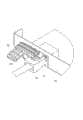
图1是本发明连接器拔出辅助装置的较佳实施方式与一电子装置及一连接器的立体分解图。FIG. 1 is a three-dimensional exploded view of a preferred embodiment of the connector pulling-out assisting device of the present invention, an electronic device and a connector.
图2是图1中的按压件的另一方向视图。Fig. 2 is another direction view of the pressing part in Fig. 1 .
图3是图1中的连接器拔出辅助装置于另一方向的立体组装图。FIG. 3 is a three-dimensional assembled view of the connector pulling-out assisting device in FIG. 1 in another direction.
图4与图5是图1组装后于不同状态下的立体视图。FIG. 4 and FIG. 5 are perspective views of FIG. 1 in different states after being assembled.
主要元件符号说明Description of main component symbols
如下具体实施方式将结合上述附图进一步说明本发明。The following specific embodiments will further illustrate the present invention in conjunction with the above-mentioned drawings.
具体实施方式Detailed ways
请参照图1与图4,本发明连接器拔出辅助装置的较佳实施方式,用以辅助一连接器10从一对接的电子装置20的连接器插槽210中拔出。该连接器拔出辅助装置包括一固定件30、一按压件40与一扭簧50。Please refer to FIG. 1 and FIG. 4 , a preferred embodiment of the connector pulling-out assisting device of the present invention is used to assist a
该连接器10的顶部于前端设有一向后上方倾斜延伸的可卡置于该连接器插槽210的弹性卡扣12。The top of the
该电子装置20具有一侧壁21。该连接器插槽210设于侧壁21。该侧壁21于该连接器插槽210的一侧设有一穿孔213及一卡槽215。The electronic device 20 has a
该固定件30包括一固定板31。该固定板31的中部设有一通孔312。该固定板31的两侧分别向后垂直延伸形成两相对的侧板33。每一侧板33的中部设有一穿孔332。该固定板31的顶部向前延伸一卡固片35。该固定板31的底部后垂直延伸一挡板37。该挡板37邻近其中一侧板33设有一固定孔371(见图3)。The fixing member 30 includes a fixing plate 31 . A through hole 312 is defined in a middle portion of the fixing plate 31 . Both sides of the fixing plate 31 extend vertically backward respectively to form two
请一并参照图2,该按压件40包括一主体部41。该主体部41的两侧的前端分别向下垂直延伸形成两相对的枢接部43。每一枢接部43于邻近前端处设有一枢接孔432。该主体部41的一侧向外延伸出一按压部45。Please refer to FIG. 2 together, the
请参照图3与图4,组装时,首先将该固定件30的卡固片35插入该电子装置20的卡槽215,通过一拉钉70穿过该通孔312及该穿孔213而将该固定板31固定于该电子装置20的侧壁21。然后将该按压件40的两枢接部43分别贴靠于该固定件30的两侧板33的内侧。将一销轴60依次穿过一侧板33的穿孔332、一对应的枢接部43的枢接孔432、该扭簧50的中部、另一枢接部43的枢接孔432及另一侧板33的穿孔332,从而将该按压件40枢转地连连接于该固定件30。将该扭簧50的一端穿插于该固定件30的挡板37的固定孔371,另一端抵接于该主体部41的内侧。该扭簧50处于自然状态时,该按压件40的按压部45水平位于该连接器插槽210的上方。Please refer to FIG. 3 and FIG. 4 , when assembling, first insert the clamping piece 35 of the fixing member 30 into the slot 215 of the electronic device 20, and pass a pull nail 70 through the through hole 312 and the through hole 213 to secure the The fixing plate 31 is fixed on the
请参照图5,要拔出插接于该连接器插槽210的连接器10时,向下按压该主体部41的后端,使该主体部41的后端与该按压部45的后端向下转动,该按压部45的后端向下按压该连接器10的弹性卡扣12,使该弹性卡扣12脱离该连接器插槽210的卡置,即可方便的向后拔出该连接器10。Please refer to FIG. 5 , when the
在其他实施方式中,该按压件40的两枢接部43可分别贴靠于该固定件30的两侧板33的外侧安装。In other embodiments, the two
Claims (5)
Priority Applications (3)
| Application Number | Priority Date | Filing Date | Title |
|---|---|---|---|
| CN201210058079.4ACN103311736A (en) | 2012-03-07 | 2012-03-07 | Connector pulling-out assisting device |
| TW101108972ATW201338296A (en) | 2012-03-07 | 2012-03-15 | Assisting apparatus for unplunging connector |
| US13/488,456US8512062B1 (en) | 2012-03-07 | 2012-06-05 | Electronic device having assisting apparatus for unplugging RJ-45 connector |
Applications Claiming Priority (1)
| Application Number | Priority Date | Filing Date | Title |
|---|---|---|---|
| CN201210058079.4ACN103311736A (en) | 2012-03-07 | 2012-03-07 | Connector pulling-out assisting device |
Publications (1)
| Publication Number | Publication Date |
|---|---|
| CN103311736Atrue CN103311736A (en) | 2013-09-18 |
Family
ID=48952094
Family Applications (1)
| Application Number | Title | Priority Date | Filing Date |
|---|---|---|---|
| CN201210058079.4APendingCN103311736A (en) | 2012-03-07 | 2012-03-07 | Connector pulling-out assisting device |
Country Status (3)
| Country | Link |
|---|---|
| US (1) | US8512062B1 (en) |
| CN (1) | CN103311736A (en) |
| TW (1) | TW201338296A (en) |
Cited By (2)
| Publication number | Priority date | Publication date | Assignee | Title |
|---|---|---|---|---|
| CN108173077A (en)* | 2017-12-28 | 2018-06-15 | 高苑 | A kind of push type USB interface mobile charging lithium battery easy to plug |
| CN109742638A (en)* | 2018-12-25 | 2019-05-10 | 郑州云海信息技术有限公司 | A chassis network cable crystal head extracting device |
Families Citing this family (7)
| Publication number | Priority date | Publication date | Assignee | Title |
|---|---|---|---|---|
| CN103682820A (en)* | 2012-08-30 | 2014-03-26 | 鸿富锦精密工业(深圳)有限公司 | Electronic device and connector pulling auxiliary part |
| CN104577511A (en)* | 2014-12-30 | 2015-04-29 | 孙冬梅 | Plug |
| EP3512049B1 (en) | 2018-01-16 | 2020-12-30 | Tyco Electronics (Shanghai) Co. Ltd. | Connector housing and connector |
| US11542284B2 (en) | 2019-04-02 | 2023-01-03 | Gelest, Inc. | Chalcogenosilacyclopentanes |
| US11646532B1 (en)* | 2021-11-03 | 2023-05-09 | Dell Products L.P. | Connector release system |
| DE102022133926A1 (en)* | 2022-12-19 | 2024-06-20 | Endress+Hauser Conducta Gmbh+Co. Kg | Electronic housing |
| US20240380164A1 (en)* | 2023-05-11 | 2024-11-14 | Dell Products L.P. | Seesaw assembly with a connector retaining latch disengagement mechanism |
Family Cites Families (10)
| Publication number | Priority date | Publication date | Assignee | Title |
|---|---|---|---|---|
| US5308260A (en)* | 1992-09-01 | 1994-05-03 | Hubbell Incorporated | Front releasable modular telecommunication jack adapter |
| US7314384B2 (en)* | 2001-10-04 | 2008-01-01 | Finisar Corporation | Electronic modules having an integrated connector detachment mechanism |
| US7037141B1 (en)* | 2005-02-08 | 2006-05-02 | Huang-Chou Huang | Communication socket having a channel transversely defined in the body and a plug identifying member securely received in the channel |
| US7326075B1 (en)* | 2005-06-17 | 2008-02-05 | Juniper Networks, Inc. | Remote release of a cable connector |
| US20070270016A1 (en)* | 2006-05-22 | 2007-11-22 | Dell Products L.P. | Method and apparatus for coupling a cable to a socket |
| CN200956456Y (en)* | 2006-08-30 | 2007-10-03 | 鸿富锦精密工业(深圳)有限公司 | connector ejector |
| US7800037B2 (en)* | 2007-04-30 | 2010-09-21 | Carl Keith Sawtell | Power supply control circuit with optical feedback |
| US7651361B2 (en)* | 2008-04-30 | 2010-01-26 | Tyco Electronics Corporation | Electrical connector having pull tether for latch release |
| CN102544903A (en)* | 2010-12-28 | 2012-07-04 | 鸿富锦精密工业(深圳)有限公司 | Auxiliary device for pulling out crystal head and crystal head combination |
| CN103036104A (en)* | 2011-09-30 | 2013-04-10 | 鸿富锦精密工业(深圳)有限公司 | Connector plug auxiliary device and connector assembly |
- 2012
- 2012-03-07CNCN201210058079.4Apatent/CN103311736A/enactivePending
- 2012-03-15TWTW101108972Apatent/TW201338296A/enunknown
- 2012-06-05USUS13/488,456patent/US8512062B1/ennot_activeExpired - Fee Related
Cited By (2)
| Publication number | Priority date | Publication date | Assignee | Title |
|---|---|---|---|---|
| CN108173077A (en)* | 2017-12-28 | 2018-06-15 | 高苑 | A kind of push type USB interface mobile charging lithium battery easy to plug |
| CN109742638A (en)* | 2018-12-25 | 2019-05-10 | 郑州云海信息技术有限公司 | A chassis network cable crystal head extracting device |
Also Published As
| Publication number | Publication date |
|---|---|
| US8512062B1 (en) | 2013-08-20 |
| US20130237082A1 (en) | 2013-09-12 |
| TW201338296A (en) | 2013-09-16 |
Similar Documents
| Publication | Publication Date | Title |
|---|---|---|
| CN103311736A (en) | Connector pulling-out assisting device | |
| CN207120985U (en) | The inserted-link type supporting mechanism of the side box plate of folding shopping case two | |
| CN201097288Y (en) | Computer magnetic rack | |
| CN103763986A (en) | Drawer | |
| CN214876350U (en) | Tray box | |
| TWM305950U (en) | Swap device | |
| CN104184022A (en) | Auxiliary device for pull-out of connector | |
| CN102789281A (en) | Universal serial bus (USB) connector interface and USB connector combination | |
| US20130263708A1 (en) | Fixing device for a tool member | |
| CN208822017U (en) | A kind of bindiny mechanism of side plate of the drawer and backboard | |
| WO2018006488A1 (en) | Expanding connection buckle | |
| CN103209562B (en) | The fixture of electronic component | |
| EP2161602A1 (en) | A fiber connector using hooking structure | |
| CN202308607U (en) | Fastening and positioning structure for electronic card | |
| CN202564685U (en) | SATA electric connector | |
| CN206744726U (en) | A female buckle of a safety buckle and the safety buckle | |
| CN103853282A (en) | Adapter assembling module | |
| CN201439665U (en) | Door fastener clip assembly | |
| CN2433708Y (en) | Improvement of HDD extraction frame structure | |
| CN202035561U (en) | Key buckle | |
| CN104602472B (en) | Without screw buckle structure | |
| CN204304157U (en) | The metal decking frame assembly of switch on wall or wall socket | |
| CN103682820A (en) | Electronic device and connector pulling auxiliary part | |
| CN214664257U (en) | Pre-embedded device for ceiling lamps | |
| CN201709766U (en) | A combination structure of a vertical cabinet |
Legal Events
| Date | Code | Title | Description |
|---|---|---|---|
| C06 | Publication | ||
| PB01 | Publication | ||
| C02 | Deemed withdrawal of patent application after publication (patent law 2001) | ||
| WD01 | Invention patent application deemed withdrawn after publication | Application publication date:20130918 |