CN103309830A - Driver of CPCI bus CAN communicating module under VxWorks operating system and driving method - Google Patents
Driver of CPCI bus CAN communicating module under VxWorks operating system and driving methodDownload PDFInfo
- Publication number
- CN103309830A CN103309830ACN201310284602XACN201310284602ACN103309830ACN 103309830 ACN103309830 ACN 103309830ACN 201310284602X ACN201310284602X ACN 201310284602XACN 201310284602 ACN201310284602 ACN 201310284602ACN 103309830 ACN103309830 ACN 103309830A
- Authority
- CN
- China
- Prior art keywords
- communication module
- function
- function interface
- board
- interface
- Prior art date
- Legal status (The legal status is an assumption and is not a legal conclusion. Google has not performed a legal analysis and makes no representation as to the accuracy of the status listed.)
- Pending
Links
- 102100029368Cytochrome P450 2C18Human genes0.000titleclaimsabstractdescription45
- 101000919360Homo sapiens Cytochrome P450 2C18Proteins0.000titleclaimsabstractdescription45
- 238000000034methodMethods0.000titleclaimsabstractdescription40
- 238000004891communicationMethods0.000claimsabstractdescription198
- 238000013468resource allocationMethods0.000claimsabstractdescription15
- 230000006870functionEffects0.000claimsdescription248
- 238000012360testing methodMethods0.000claimsdescription18
- 238000012544monitoring processMethods0.000claimsdescription16
- 238000013507mappingMethods0.000claimsdescription10
- 238000011065in-situ storageMethods0.000claimsdescription3
- 238000009434installationMethods0.000abstractdescription4
- 238000013461designMethods0.000description6
- 238000011161developmentMethods0.000description6
- 238000002955isolationMethods0.000description4
- 238000004806packaging method and processMethods0.000description3
- 238000005538encapsulationMethods0.000description2
- 230000005540biological transmissionEffects0.000description1
- 238000006243chemical reactionMethods0.000description1
- 238000007726management methodMethods0.000description1
Images


Landscapes
- Small-Scale Networks (AREA)
Abstract
Translated fromChinese
Description
Translated fromChinese技术领域technical field
本发明涉及VxWorks操作系统下CPCI总线CAN通信模块的驱动器及驱动方法,属于CPCI总线CAN通信的驱动技术领域。The invention relates to a driver and a driving method of a CPCI bus CAN communication module under a VxWorks operating system, and belongs to the driving technical field of the CPCI bus CAN communication.
背景技术Background technique
VxWorks操作系统下CPCI总线CAN通信功能模块作为自动测试系统中重要的测试模块,已经广泛的应用在各个领域中。传统的VxWorks操作系统下基于CPCI总线的CAN通信模块驱动程序的开发,是根据需要来实现相应的功能函数接口,并封装成标准的I/O接口,即七个标准的I/O接口,例如open(),close(),read()等,注册到系统驱动列表中,挂接在I/O子系统下。在这个过程中,驱动开发人员需要抽象出设备的数据结构,完成设备的创建及设备驱动程序的安装,这个过程比较复杂,给驱动开发人员带来很多不便。As an important test module in the automatic test system, the CPCI bus CAN communication function module under the VxWorks operating system has been widely used in various fields. The development of the CAN communication module driver based on the CPCI bus under the traditional VxWorks operating system is to realize the corresponding function interface according to the needs, and package it into a standard I/O interface, that is, seven standard I/O interfaces, such as open(), close(), read(), etc., are registered in the system driver list and mounted under the I/O subsystem. In this process, the driver developer needs to abstract the data structure of the device to complete the creation of the device and the installation of the device driver. This process is relatively complicated and brings a lot of inconvenience to the driver developer.
发明内容Contents of the invention
本发明是为了解决现有VxWorks操作系统下CPCI总线CAN通信驱动的实现需要首先抽象出设备的数据结构,再完成设备的创建及设备驱动的安装,过程复杂的问题,提供了一种VxWorks操作系统下CPCI总线CAN通信模块的驱动器及驱动方法。The present invention provides a VxWorks operating system in order to solve the problem that the implementation of the CPCI bus CAN communication driver under the existing VxWorks operating system needs to first abstract the data structure of the device, and then complete the creation of the device and the installation of the device driver. The driver and the driving method of the CAN communication module of the lower CPCI bus.
本发明所述VxWorks操作系统下CPCI总线CAN通信模块的驱动器,它包括:The driver of CPCI bus CAN communication module under the VxWorks operating system of the present invention, it comprises:
用于初始化CAN通信模块的系统资源分配装置;A system resource allocation device for initializing the CAN communication module;
用于提供功能函数接口的函数接口装置;Functional interface means for providing a functional functional interface;
用于面向用户应用程序封装,驱动函数接口的驱动装置。A driver device for user-oriented application package, driver function interface.
所述系统资源分配装置包括:The system resource allocation device includes:
用于获得基于CPCI总线的CAN通信模块的各个设备信息的装置;该装置包含:The device for obtaining each device information of the CAN communication module based on the CPCI bus; the device includes:
根据CAN通信模块的各个设备的Vendor ID和Device ID,利用函数pciFindDevice()对CAN通信模块的各个设备进行对应的初始化函数装置,According to the Vendor ID and Device ID of each device of the CAN communication module, use the function pciFindDevice() to perform corresponding initialization function devices on each device of the CAN communication module,
根据CAN通信模块的各个设备Vendor ID、Device ID和顺序号扫描总线,找出CAN通信模块的各个设备所在的总线号BUS No、设备号Device No和功能号Func No,再根据总线号BUS No、设备号Device No和功能号Func No调用pciConfigInLong()函数及pciConfigInByte()函数的装置,Scan the bus according to each device Vendor ID, Device ID and sequence number of the CAN communication module, find out the bus number BUS No, device number Device No and function number Func No of each device of the CAN communication module, and then according to the bus number BUS No, Device No. Device No. and Function No. Func No. call pciConfigInLong() function and pciConfigInByte() function device,
确定各个设备的寄存器基地址以及中断号,再将寄存器基地址与I/O屏蔽位相与,获得最终的CAN通信模块板上内部寄存器基地址的装置;A device that determines the register base address and interrupt number of each device, and then ANDs the register base address with the I/O mask bit to obtain the final internal register base address on the CAN communication module board;
用于对CAN通信模块的各个设备进行内存映射的装置;该装置包含:A device for memory-mapping each device of the CAN communication module; the device includes:
使用MMU来分配PCI设备的内存空间的装置,A device that uses the MMU to allocate memory space for PCI devices,
调用函数sysMmuMapAdd()将内存空间配置到MMU的装置;Call the function sysMmuMapAdd () to configure the memory space to the device of the MMU;
用于对CAN通信模块的各个设备中断链接的装置;该装置包含:A device for disconnecting various devices of the CAN communication module; the device includes:
在VxWorks系统下使用pciIntConnect()函数将各个设备指定的中断向量与指定的C程序函数连接起来,并将pciIntConnect()函数的地址存储在该指定的中断向量中的装置,Use the pciIntConnect () function under the VxWorks system to connect the interrupt vector specified by each device with the specified C program function, and store the address of the pciIntConnect () function in the specified interrupt vector.
当中断发生时,调用指定的C程序函数,中断服务的装置。When an interrupt occurs, call the specified C program function to interrupt the service device.
所述函数接口装置包括:The function interface device includes:
提供打开CAN通信模块板STATUS CANOpen函数接口,并对该函数接口加载驱动程序,打开指定的CAN通信通道的装置;Provide a device to open the STATUS CANOpen function interface of the CAN communication module board, load the driver program on the function interface, and open the specified CAN communication channel;
提供关闭CAN通信模块板STATUS CANClose函数接口,通过该函数接口不能对CAN通信模块板进行除打开以外的操作的装置;Provide a device for closing the CAN communication module board STATUS CANClose function interface, through which the CAN communication module board cannot be operated except for opening;
提供设置通道参数STATUS CANSetting函数接口,通过该函数接口对CAN通信模块板指定通道进行参数设置的装置;Provide a function interface for setting channel parameters STATUS CANSetting, and use this function interface to set the parameters of the specified channel of the CAN communication module board;
提供发送数据STATUS CANSendData函数接口,通过该函数接口对CAN通信模块板指定的一路通道写入待发送的数据的装置;同时在发送多帧数据消息时,循环调用该函数接口的装置;Provide the function interface of sending data STATUS CANSendData, and write the device of the data to be sent to the channel specified by the CAN communication module board through the function interface; at the same time, when sending multi-frame data messages, the device of the function interface is called cyclically;
提供接收等待STATUS CANRecvWait函数接口,通过该函数接口对CAN通信模块板的板号进行指定,并等待指定的一路通道接收缓存内的数据就绪的装置;Provide a function interface for receiving and waiting for STATUS CANRecvWait, through which the board number of the CAN communication module board is specified, and the device that waits for the data in the specified channel to receive the data in the buffer is ready;
提供接收数据int CANRecvData函数接口,通过该函数接口对CAN通信模块板的板号进行指定,并读取指定的一路通道接收缓存内的数据的装置;Provide the receiving data int CANRecvData function interface, specify the board number of the CAN communication module board through the function interface, and read the designated one channel to receive the data in the cache;
提供通信板自检STATUS CANTest函数接口,通过该函数接口对CAN通信模块板进行自检的装置;Provide communication board self-test STATUS CANTest function interface, through this function interface, a device for self-testing CAN communication module board;
提供通信板复位STATUS CANReset函数接口,通过该函数接口对CAN通信模块板进行复位操作的装置;Provide communication board reset STATUS CANReset function interface, and reset the CAN communication module board through this function interface;
提供实时监测STATUS CANRTWatch函数接口,通过该函数接口对CAN通信模块板进行在位实时监测的装置。It provides a real-time monitoring STATUS CANRTWatch function interface, and a device for on-site real-time monitoring of the CAN communication module board through this function interface.
一种VxWorks操作系统下CPCI总线CAN通信模块的驱动方法,它包括:A driving method of a CPCI bus CAN communication module under a VxWorks operating system, comprising:
用于初始化CAN通信模块的系统资源分配步骤;A system resource allocation step for initializing the CAN communication module;
用于提供功能函数接口的步骤;Steps for providing a functional function interface;
用于面向用户应用程序封装,驱动函数接口的驱动步骤。It is used for encapsulating user-oriented application programs and driving steps of the driver function interface.
所述系统资源分配步骤包括:The system resource allocation step includes:
用于获得基于CPCI总线的CAN通信模块的各个设备信息的步骤;该步骤包含:The step for obtaining the information of each device of the CAN communication module based on the CPCI bus; the step includes:
根据CAN通信模块的各个设备的Vendor ID和Device ID,利用函数pciFindDevice()对CAN通信模块的各个设备进行对应的初始化函数步骤,According to the Vendor ID and Device ID of each device of the CAN communication module, use the function pciFindDevice() to perform corresponding initialization function steps on each device of the CAN communication module,
根据CAN通信模块的各个设备Vendor ID、Device ID和顺序号扫描总线,找出CAN通信模块的各个设备所在的总线号BUS No、设备号Device No和功能号Func No,再根据总线号BUS No、设备号Device No和功能号Func No调用pciConfigInLong()函数及pciConfigInByte()函数的步骤,Scan the bus according to each device Vendor ID, Device ID and sequence number of the CAN communication module, find out the bus number BUS No, device number Device No and function number Func No of each device of the CAN communication module, and then according to the bus number BUS No, Steps to call the pciConfigInLong() function and pciConfigInByte() function with the device number Device No and function number Func No,
确定各个设备的寄存器基地址以及中断号,再将寄存器基地址与I/O屏蔽位相与,获得最终的CAN通信模块板上内部寄存器基地址的步骤;Determine the register base address and interrupt number of each device, and then AND the register base address with the I/O mask bit to obtain the final internal register base address on the CAN communication module board;
用于对CAN通信模块的各个设备进行内存映射的步骤;该步骤包含:A step for performing memory mapping on each device of the CAN communication module; the step includes:
使用MMU来分配PCI设备的内存空间的步骤,Steps to use the MMU to allocate memory space for PCI devices,
调用函数sysMmuMapAdd()将内存空间配置到MMU的步骤;The step of calling the function sysMmuMapAdd() to configure the memory space to the MMU;
用于对CAN通信模块的各个设备中断链接的步骤;该步骤包含:A step for disconnecting each device of the CAN communication module; the step includes:
在VxWorks系统下使用pciIntConnect()函数将各个设备指定的中断向量与指定的C程序函数连接起来,并将pciIntConnect()函数的地址存储在该指定的中断向量中的步骤,Use the pciIntConnect() function under the VxWorks system to connect the interrupt vector specified by each device with the specified C program function, and store the address of the pciIntConnect() function in the specified interrupt vector,
当中断发生时,调用指定的C程序函数,中断服务的步骤。When an interrupt occurs, call the specified C program function to interrupt the service steps.
所述用于提供功能函数接口的步骤包括:The steps for providing a functional interface include:
提供打开CAN通信模块板STATUS CANOpen函数接口,并对该函数接口加载驱动程序,打开指定的CAN通信通道的步骤;Provide the steps of opening the STATUS CANOpen function interface of the CAN communication module board, and loading the driver program to the function interface, and opening the specified CAN communication channel;
提供关闭CAN通信模块板STATUS CANClose函数接口,通过该函数接口不能对CAN通信模块板进行除打开以外的操作的步骤;Provide a function interface for closing the CAN communication module board STATUS CANClose, through which the CAN communication module board cannot be operated except for opening;
提供设置通道参数STATUS CANSetting函数接口,通过该函数接口对CAN通信模块板指定通道进行参数设置的步骤;Provide a function interface for setting channel parameters STATUS CANSetting, and use this function interface to perform parameter setting steps for the specified channel of the CAN communication module board;
提供发送数据STATUS CANSendData函数接口,通过该函数接口对CAN通信模块板指定的一路通道写入待发送的数据的步骤;同时在发送多帧数据消息时,循环调用该函数接口的步骤;Provide the function interface of sending data STATUS CANSendData, through the function interface, the step of writing the data to be sent to one channel specified by the CAN communication module board; at the same time, when sending multi-frame data messages, the step of calling the function interface cyclically;
提供接收等待STATUS CANRecvWait函数接口,通过该函数接口对CAN通信模块板的板号进行指定,并等待指定的一路通道接收缓存内的数据就绪的步骤;Provide receiving and waiting STATUS CANRecvWait function interface, specify the board number of the CAN communication module board through this function interface, and wait for the step of receiving the data in the specified channel to receive the buffer;
提供接收数据int CANRecvData函数接口,通过该函数接口对CAN通信模块板的板号进行指定,并读取指定的一路通道接收缓存内的数据的步骤;Provide the receiving data int CANRecvData function interface, specify the board number of the CAN communication module board through the function interface, and read the steps of receiving data in the specified channel receiving buffer;
提供通信板自检STATUS CANTest函数接口,通过该函数接口对CAN通信模块板进行自检的步骤;Provide communication board self-test STATUS CANTest function interface, through the function interface to self-test the CAN communication module board;
提供通信板复位STATUS CANReset函数接口,通过该函数接口对CAN通信模块板进行复位操作的步骤;Provide communication board reset STATUS CANReset function interface, and reset the CAN communication module board through this function interface;
提供实时监测STATUS CANRTWatch函数接口,通过该函数接口对CAN通信模块板进行在位实时监测的步骤。Provide a real-time monitoring STATUS CANRTWatch function interface, through which the in-situ real-time monitoring of the CAN communication module board is performed.
本发明的优点:本发明所述驱动器或驱动方法针对VxWorks操作系统下CPCI总线CAN通信功能模块,提出了新的驱动设计及封装形式,在实现对CAN通信功能模块有效控制的同时,在很大程序上降低了驱动开发人员的开发难度。Advantage of the present invention: driver or driving method described in the present invention is aimed at CPCI bus CAN communication function module under VxWorks operating system, proposes new drive design and packaging form, while realizing effective control to CAN communication function module, greatly Programmatically reduces the development difficulty of driver developers.
本发明根据CAN通信功能模块的特点,提供了一种新的CAN通信功能模块的驱动接口封装形式,它面向应用程序直接定义驱动接口的形式,直接封装功能接口函数。这样在驱动开发的过程中,不涉及到传统CAN通信功能模块的设备数据结构的设计、设备创建及驱动安装,使CAN通信功能模块的驱动过程变得简单易实现。According to the characteristics of the CAN communication function module, the invention provides a new encapsulation form of the drive interface of the CAN communication function module, which directly defines the form of the drive interface and directly encapsulates the function of the function interface facing the application program. In this way, in the process of driver development, the design of device data structure, device creation and driver installation of traditional CAN communication function modules are not involved, so that the driving process of CAN communication function modules becomes simple and easy to implement.
本发明所述驱动器及驱动方法能够实现对CAN通信功能模块的有效控制;它直接面向用户应用程序提供通用的驱动函数接口;具有独立性与通用性,可应用于其它设计。The driver and the driving method of the invention can effectively control the CAN communication function module; it directly provides a general driving function interface for user application programs; it has independence and versatility, and can be applied to other designs.
附图说明Description of drawings
图1是本发明所述VxWorks操作系统下CPCI总线CAN通信模块的架构示意图;Fig. 1 is the structural representation of CPCI bus CAN communication module under the VxWorks operating system of the present invention;
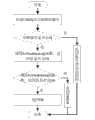
图2是系统资源分配过程中的初始化函数流程图;Fig. 2 is the initialization function flowchart in the system resource allocation process;
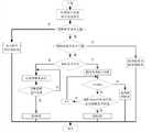
图3是功能函数接口的控制过程流程图;Fig. 3 is the flow chart of the control process of the functional function interface;
图4是打开CAN通信模块板的函数接口的实现过程流程图;Fig. 4 is the flow chart of the realization process of opening the function interface of the CAN communication module board;
图5是关闭CAN通信模块板的函数接口的实现过程流程图;Fig. 5 is the realization process flowchart of closing the function interface of CAN communication module board;
图6是设置通道参数STATUS CANSetting函数接口的实现过程流程图;Fig. 6 is the flow chart of the implementation process of setting the channel parameter STATUS CANSetting function interface;
图7是发送数据函数接口的实现过程流程图;Fig. 7 is the realization process flowchart of sending data function interface;
图8是接收等待函数接口的实现过程流程图;Fig. 8 is the flow chart of the implementation process of receiving the waiting function interface;
图9是接收数据函数接口的实现过程流程图;Fig. 9 is the flow chart of the implementation process of the interface for receiving data functions;
图10是通信板自检函数接口的实现过程流程图;Fig. 10 is the flow chart of the realization process of the communication board self-test function interface;
图11是通信板复位函数接口的实现过程流程图;Fig. 11 is the realization process flowchart of communication board reset function interface;
图12是在位实时监测函数接口的实现过程流程图。Fig. 12 is a flowchart of the realization process of the on-site real-time monitoring function interface.
具体实施方式Detailed ways
具体实施方式一:下面结合图1至图3说明本实施方式,本实施方式所述VxWorks操作系统下CPCI总线CAN通信模块的驱动器,它包括:Specific embodiment one: below in conjunction with Fig. 1 to Fig. 3 illustrate present embodiment, the driver of CPCI bus CAN communication module under VxWorks operating system described in present embodiment, it comprises:
用于初始化CAN通信模块的系统资源分配装置;A system resource allocation device for initializing the CAN communication module;
用于提供功能函数接口的函数接口装置;Functional interface means for providing a functional functional interface;
用于面向用户应用程序封装,驱动函数接口的驱动装置。A driver device for user-oriented application package, driver function interface.
本实施方式中CAN通信模块的整体架构如图1所示,下述解释说明同样适用于具体实施方式四:CAN通信模块运行在CPCI机箱中,控制计算机通过CPCI总线实现对CAN通信功能模块的读写控制。CPCI总线和CAN通信功能电路之间需要实现CPCI总线接口控制器,CPCI总线接口控制器采用PLX公司的PCI9054接口芯片实现,将CPCI总线转换到本地总线。PCI9054接口芯片完全兼容PCI2.2规范,且突发数据传输速率高,同时接口芯片价格低,通用性好,可以有效减小开发难度。PCI9054本地总线侧使用FPGA实现总线接口译码,同时,FPGA内部设计控制寄存器,实现对CAN通信功能电路的控制。CAN通信功能部分由CAN控制器SJA1000T、隔离芯片6N137、CAN接口芯片SN65HVD1050和隔离电源DCP02055P构成。外部输入的CAN通信信号经过CAN接口芯片后,输入到光耦隔离芯片6N137,然后经过CAN控制器后,输入到FPGA可编程逻辑芯片,从而传输到CPCI总线上。而来自CPCI总线的发送信号,经过FPGA处理后,通过CAN控制器、光耦隔离芯片6N137和CAN接口芯片,输出到CAN的输出通道。The overall architecture of the CAN communication module in this embodiment is shown in Figure 1, and the following explanations are also applicable to Embodiment 4: the CAN communication module runs in the CPCI chassis, and the control computer realizes the reading of the CAN communication function module through the CPCI bus. write control. The CPCI bus interface controller needs to be implemented between the CPCI bus and the CAN communication function circuit. The CPCI bus interface controller is realized by the PCI9054 interface chip of PLX Company, and converts the CPCI bus to the local bus. The PCI9054 interface chip is fully compatible with the PCI2.2 specification, and has a high burst data transmission rate. At the same time, the interface chip has low price and good versatility, which can effectively reduce the difficulty of development. The PCI9054 local bus side uses FPGA to realize the bus interface decoding, and at the same time, the control register is designed inside the FPGA to realize the control of the CAN communication function circuit. CAN communication function part is composed of CAN controller SJA1000T, isolation chip 6N137, CAN interface chip SN65HVD1050 and isolation power supply DCP02055P. The CAN communication signal input from the outside passes through the CAN interface chip, then is input to the optocoupler isolation chip 6N137, and then after passing through the CAN controller, it is input to the FPGA programmable logic chip, and then transmitted to the CPCI bus. The signal sent from the CPCI bus is processed by the FPGA, and then output to the CAN output channel through the CAN controller, the optocoupler isolation chip 6N137 and the CAN interface chip.
CAN通信功能模块驱动器的设计:CAN communication function module driver design:
CAN通信功能模块运行在CPCI机箱中,运行在控制计算机上的应用程序,通过CPCI总线实现对CAN通信功能模块的控制,因此需要开发基于CPCI总线CAN通信功能模块的驱动器。CAN通信功能模块的驱动器设计主要包括初始化设备,功能函数接口的实现及封装。The CAN communication function module runs in the CPCI chassis, and the application program running on the control computer realizes the control of the CAN communication function module through the CPCI bus. Therefore, it is necessary to develop a driver for the CAN communication function module based on the CPCI bus. The driver design of the CAN communication function module mainly includes the initialization device, the realization and packaging of the function interface.
具体实施方式二:下面结合图2说明本实施方式,本实施方式对实施方式一作进一步说明,本实施方式所述系统资源分配装置包括:Specific implementation mode two: the following describes this implementation mode in conjunction with FIG. 2 . This implementation mode further explains implementation mode one. The system resource allocation device described in this implementation mode includes:
用于获得基于CPCI总线的CAN通信模块的各个设备信息的装置;该装置包含:The device for obtaining each device information of the CAN communication module based on the CPCI bus; the device includes:
根据CAN通信模块的各个设备的Vendor ID和Device ID,利用函数pciFindDevice()对CAN通信模块的各个设备进行对应的初始化函数装置,According to the Vendor ID and Device ID of each device of the CAN communication module, use the function pciFindDevice() to perform corresponding initialization function devices on each device of the CAN communication module,
根据CAN通信模块的各个设备Vendor ID、Device ID和顺序号扫描总线,找出CAN通信模块的各个设备所在的总线号BUS No、设备号Device No和功能号Func No,再根据总线号BUS No、设备号Device No和功能号Func No调用pciConfigInLong()函数及pciConfigInByte()函数的装置,Scan the bus according to each device Vendor ID, Device ID and sequence number of the CAN communication module, find out the bus number BUS No, device number Device No and function number Func No of each device of the CAN communication module, and then according to the bus number BUS No, Device No. Device No. and Function No. Func No. call pciConfigInLong() function and pciConfigInByte() function device,
确定各个设备的寄存器基地址以及中断号,再将寄存器基地址与I/O屏蔽位相与,获得最终的CAN通信模块板上内部寄存器基地址的装置;A device that determines the register base address and interrupt number of each device, and then ANDs the register base address with the I/O mask bit to obtain the final internal register base address on the CAN communication module board;
用于对CAN通信模块的各个设备进行内存映射的装置;该装置包含:A device for memory-mapping each device of the CAN communication module; the device includes:
使用MMU来分配PCI设备的内存空间的装置,A device that uses the MMU to allocate memory space for PCI devices,
调用函数sysMmuMapAdd()将内存空间配置到MMU的装置;Call the function sysMmuMapAdd () to configure the memory space to the device of the MMU;
用于对CAN通信模块的各个设备中断链接的装置;该装置包含:A device for disconnecting various devices of the CAN communication module; the device includes:
在VxWorks系统下使用pciIntConnect()函数将各个设备指定的中断向量与指定的C程序函数连接起来,并将pciIntConnect()函数的地址存储在该指定的中断向量中的装置,Use the pciIntConnect () function under the VxWorks system to connect the interrupt vector specified by each device with the specified C program function, and store the address of the pciIntConnect () function in the specified interrupt vector.
当中断发生时,调用指定的C程序函数,中断服务的装置。When an interrupt occurs, call the specified C program function to interrupt the service device.
本实施方式中,Vendor ID表示设备的厂商号,Device ID表示设备号,函数pciFindDevice()用于扫描CPCI总线上的设备,pciConfigInLong()函数用于读取CAN通信模块的配置空间,pciConfigInByte()函数用于读取CAN通信模块的配置空间,函数sysMmuMapAdd()用于完成CAN通信模块的设备内存映射,pciIntConnect()函数用于完成CAN通信模块的中断连接。In this embodiment, Vendor ID represents the manufacturer number of the device, Device ID represents the device number, the function pciFindDevice () is used to scan the equipment on the CPCI bus, the pciConfigInLong () function is used to read the configuration space of the CAN communication module, pciConfigInByte () The function is used to read the configuration space of the CAN communication module, the function sysMmuMapAdd() is used to complete the device memory mapping of the CAN communication module, and the pciIntConnect() function is used to complete the interrupt connection of the CAN communication module.
下面对本实施方式的具体实现进行详细说明,下述解释说明同样适用于具体实施方式五:The specific implementation of this embodiment will be described in detail below, and the following explanations are also applicable to the fifth embodiment:
初始化设备作为CPCI设备驱动开发的重要环节,主要是为硬件分配系统资源,这里主要是获取基于CPCI总线的CAN通信功能模块的设备信息、设备内存映射及中断链接,如图2所示。As an important link in the development of CPCI device drivers, the initialization device is mainly to allocate system resources for the hardware. Here, it is mainly to obtain the device information, device memory mapping and interrupt link of the CAN communication function module based on the CPCI bus, as shown in Figure 2.
1)获取基于CPCI总线的CAN通信功能模块的设备信息:1) Obtain the device information of the CAN communication function module based on the CPCI bus:
PCI设备上电后,BIOS会配置PCI设备。目标机的BIOS在启动时会有一个界面列出找到的PCI设备及Vendor ID、Device ID、设备类型、分配的中断号等信息。After the PCI device is powered on, the BIOS configures the PCI device. When the BIOS of the target machine starts, there will be an interface listing the found PCI devices, Vendor ID, Device ID, device type, assigned interrupt number and other information.
初始化函数先根据设备Vendor ID和Device ID利用函数pciFindDevice()找到对应的设备,根据Vendor ID、Device ID和相同设备顺序号来扫描总线,找出设备所在的BUS No、Device No和Func No。然后根据总线号、设备号和功能号调用pciConfigInLong()及pciConfigInByte()函数确定设备的寄存器基地址以及中断号。再把基地址与I/O屏蔽位相与得到真正的板上内部寄存器基地址。初始化函数流程如下图2所示。The initialization function first uses the function pciFindDevice() to find the corresponding device according to the device Vendor ID and Device ID, scans the bus according to the Vendor ID, Device ID and the sequence number of the same device, and finds out the BUS No, Device No and Func No where the device is located. Then call the pciConfigInLong() and pciConfigInByte() functions according to the bus number, device number and function number to determine the register base address and interrupt number of the device. Then compare the base address with the I/O mask phase to obtain the real base address of the internal register on the board. The initialization function flow is shown in Figure 2 below.
2)设备内存映射:2) Device memory map:
VxWorks提供了标准的MMU,即内存管理单元,用户可以使用MMU来分配PCI设备的内存空间。在明确基地址和内存空间大小后,调用函数sysMmuMapAdd()函数即可将内存空间配置到MMU。完成了CAN通信功能模块的设备内存映射后,可以通过对设备内存的访问,实现对设备的控制。VxWorks provides a standard MMU, that is, a memory management unit. Users can use the MMU to allocate memory space for PCI devices. After specifying the base address and the size of the memory space, call the function sysMmuMapAdd() to configure the memory space to the MMU. After completing the device memory mapping of the CAN communication function module, the device can be controlled by accessing the device memory.
3)中断链接:3) Broken link:
VxWorks操作系统中使用intConnect()链接中断服务程序ISR,但对于CPCI设备,一般采用pciIntConncet()挂接中断,它与intConnect()的主要不同在于intConnect()使用的中断向量是独占的,而pciIntConncet()则可使多个外部中断共享一个中断向量。pciIntConncet()定义在pciIntLib.c中,使用时应包含头文件pciIntLib.h。应注意ventor是中断矢量,需要通过INUM_TO_IVEC换算获得。In the VxWorks operating system, intConnect() is used to link the interrupt service routine ISR, but for CPCI devices, pciIntConncet() is generally used to connect interrupts. The main difference between it and intConnect() is that the interrupt vector used by intConnect() is exclusive, while pciIntConncet () allows multiple external interrupts to share one interrupt vector. pciIntConncet() is defined in pciIntLib.c, and the header file pciIntLib.h should be included when used. It should be noted that ventor is an interrupt vector and needs to be obtained through INUM_TO_IVEC conversion.
在VxWorks系统下使用pciIntConnect()函数将中断向量和特定的C程序函数连接起来后,函数的地址将存储在这个中断向量中。当中断发生时,系统将调用这个特定的C程序函数,即中断服务程序。After using the pciIntConnect() function to connect the interrupt vector with a specific C program function under the VxWorks system, the address of the function will be stored in this interrupt vector. When an interrupt occurs, the system will call this specific C program function, the interrupt service routine.
具体实施方式三:下面结合图3至图12说明本实施方式,本实施方式对实施方式二作进一步说明,本实施方式所述函数接口装置包括:Specific implementation mode three: the following describes this implementation mode in conjunction with Fig. 3 to Fig. 12. This implementation mode further explains implementation mode two. The function interface device described in this implementation mode includes:
提供打开CAN通信模块板STATUS CANOpen函数接口,并对该函数接口加载驱动程序,打开指定的CAN通信通道的装置;Provide a device to open the STATUS CANOpen function interface of the CAN communication module board, load the driver program on the function interface, and open the specified CAN communication channel;
提供关闭CAN通信模块板STATUS CANClose函数接口,通过该函数接口不能对CAN通信模块板进行除打开以外的操作的装置;Provide a device for closing the CAN communication module board STATUS CANClose function interface, through which the CAN communication module board cannot be operated except for opening;
提供设置通道参数STATUS CANSetting函数接口,通过该函数接口对CAN通信模块板指定通道进行参数设置的装置;Provide a function interface for setting channel parameters STATUS CANSetting, and use this function interface to set the parameters of the specified channel of the CAN communication module board;
提供发送数据STATUS CANSendData函数接口,通过该函数接口对CAN通信模块板指定的一路通道写入待发送的数据的装置;同时在发送多帧数据消息时,循环调用该函数接口的装置;Provide the function interface of sending data STATUS CANSendData, and write the device of the data to be sent to the channel specified by the CAN communication module board through the function interface; at the same time, when sending multi-frame data messages, the device of the function interface is called cyclically;
提供接收等待STATUS CANRecvWait函数接口,通过该函数接口对CAN通信模块板的板号进行指定,并等待指定的一路通道接收缓存内的数据就绪的装置;Provide a function interface for receiving and waiting for STATUS CANRecvWait, through which the board number of the CAN communication module board is specified, and the device that waits for the data in the specified channel to receive the data in the buffer is ready;
提供接收数据int CANRecvData函数接口,通过该函数接口对CAN通信模块板的板号进行指定,并读取指定的一路通道接收缓存内的数据的装置;Provide the receiving data int CANRecvData function interface, specify the board number of the CAN communication module board through the function interface, and read the designated one channel to receive the data in the cache;
提供通信板自检STATUS CANTest函数接口,通过该函数接口对CAN通信模块板进行自检的装置;Provide communication board self-test STATUS CANTest function interface, through this function interface, a device for self-testing CAN communication module board;
提供通信板复位STATUS CANReset函数接口,通过该函数接口对CAN通信模块板进行复位操作的装置;Provide communication board reset STATUS CANReset function interface, and reset the CAN communication module board through this function interface;
提供实时监测STATUS CANRTWatch函数接口,通过该函数接口对CAN通信模块板进行在位实时监测的装置。It provides a real-time monitoring STATUS CANRTWatch function interface, and a device for on-site real-time monitoring of the CAN communication module board through this function interface.
下面对本实施方式的具体实现进行详细说明,下述解释说明同样适用于具体实施方式六:The specific implementation of this embodiment will be described in detail below, and the following explanations are also applicable to the sixth embodiment:
本实施方式中功能函数接口的实现:The implementation of the functional function interface in this embodiment:
CAN总线功能电路部分主要完成4路CAN总线接口,CAN总线通信的主要控制过程如下图3所示。根据硬件设计人员提供的驱动硬件接口寄存器手册,操作具体的寄存器来实现主要控制过程。The CAN bus function circuit part mainly completes the 4-way CAN bus interface, and the main control process of the CAN bus communication is shown in Figure 3 below. According to the driver hardware interface register manual provided by the hardware designer, operate specific registers to realize the main control process.
对于CAN通信功能模块的操作,常见的主要有打开、关闭、发送数据、接收等待、接收数据、自检、复位及在位实时监测操作。CAN通信模块板各个驱动接口函数的详细设计如下:For the operation of the CAN communication function module, the common operations mainly include opening, closing, sending data, receiving waiting, receiving data, self-test, reset and on-site real-time monitoring operations. The detailed design of each driver interface function of the CAN communication module board is as follows:
1、打开CAN板,见表1:1. Open the CAN board, see Table 1:
表1Table 1

打开CAN板的实现流程如下图4所示。The implementation process of opening the CAN board is shown in Figure 4 below.
2、关闭CAN板,见表2:2. Turn off the CAN board, see Table 2:
表2Table 2

关闭CAN板的实现流程如图5所示。The implementation process of closing the CAN board is shown in Figure 5.
3、设置通道参数,见表3:3. Set channel parameters, see Table 3:
表3table 3

设置通道参数的实现流程如图6所示。The implementation process of setting channel parameters is shown in Figure 6.
4、发送数据,见表4:4. Send data, see Table 4:
表4Table 4


实现发送数据的流程如图7所示。The process of realizing sending data is shown in FIG. 7 .
5、接收等待,见表55. Receive and wait, see Table 5
表5table 5
实现接收等待的流程如图8所示。Figure 8 shows the process of realizing receiving and waiting.
6、接收数据,见表6:6. Receive data, see Table 6:
表6Table 6


实现接收数据的流程如图9所示。The process of realizing receiving data is shown in FIG. 9 .
7、通信板自检,见表7:7. Communication board self-test, see Table 7:
表7Table 7
通信板自检的实现流程如图10所示。The implementation process of communication board self-test is shown in Figure 10.
8、通信板复位,见表8:8. Communication board reset, see Table 8:
表8Table 8

通信板复位的流程如图11所示。The process of communication board reset is shown in Figure 11.
9、实时监测,见表9:9. Real-time monitoring, see Table 9:
表9Table 9
实时监测的实现流程如图12所示。The implementation process of real-time monitoring is shown in Figure 12.
功能函数接口的封装:Encapsulation of functional function interface:
根据对CAN通信功能模块实际控制操作开发的功能函数接口,直接面向用户应用程序封装,提供驱动接口函数。将开发的CAN通信功能模块驱动程序直接编译到VxWorks系统内核,用户在开发应用程序时,只需根据所要完成的具体操作,直接调用功能函数接口,不需要进一步封装,从而降低了驱动程序开发的难度。According to the functional function interface developed for the actual control operation of the CAN communication function module, it is directly packaged for the user application program and provides the driver interface function. The developed CAN communication function module driver is directly compiled into the VxWorks system kernel. When developing an application, the user only needs to directly call the function interface according to the specific operation to be completed without further packaging, thus reducing the driver development cost. difficulty.
具体实施方式四:下面结合图1至图3说明本实施方式,本实施方式所述VxWorks操作系统下CPCI总线CAN通信模块的驱动方法,它包括:Specific embodiment four: below in conjunction with Fig. 1 to Fig. 3 illustrate present embodiment, the driving method of CPCI bus CAN communication module under VxWorks operating system described in present embodiment, it comprises:
用于初始化CAN通信模块的系统资源分配步骤;A system resource allocation step for initializing the CAN communication module;
用于提供功能函数接口的步骤;Steps for providing a functional function interface;
用于面向用户应用程序封装,驱动函数接口的驱动步骤。It is used for encapsulating user-oriented application programs and driving steps of the driver function interface.
具体实施方式五:下面结合图2说明本实施方式,本实施方式对实施方式四作进一步说明,本实施方式所述系统资源分配步骤包括:Specific embodiment five: the present embodiment will be described below in conjunction with FIG. 2 . This embodiment will further describe embodiment four. The system resource allocation steps described in this embodiment include:
用于获得基于CPCI总线的CAN通信模块的各个设备信息的步骤;该步骤包含:The step for obtaining the information of each device of the CAN communication module based on the CPCI bus; the step includes:
根据CAN通信模块的各个设备的Vendor ID和Device ID,利用函数pciFindDevice()对CAN通信模块的各个设备进行对应的初始化函数步骤,According to the Vendor ID and Device ID of each device of the CAN communication module, use the function pciFindDevice() to perform corresponding initialization function steps on each device of the CAN communication module,
根据CAN通信模块的各个设备Vendor ID、Device ID和顺序号扫描总线,找出CAN通信模块的各个设备所在的总线号BUS No、设备号Device No和功能号Func No,再根据总线号BUS No、设备号Device No和功能号Func No调用pciConfigInLong()函数及pciConfigInByte()函数的步骤,Scan the bus according to each device Vendor ID, Device ID and sequence number of the CAN communication module, find out the bus number BUS No, device number Device No and function number Func No of each device of the CAN communication module, and then according to the bus number BUS No, Steps to call the pciConfigInLong() function and pciConfigInByte() function with the device number Device No and function number Func No,
确定各个设备的寄存器基地址以及中断号,再将寄存器基地址与I/O屏蔽位相与,获得最终的CAN通信模块板上内部寄存器基地址的步骤;Determine the register base address and interrupt number of each device, and then AND the register base address with the I/O mask bit to obtain the final internal register base address on the CAN communication module board;
用于对CAN通信模块的各个设备进行内存映射的步骤;该步骤包含:A step for performing memory mapping on each device of the CAN communication module; the step includes:
使用MMU来分配PCI设备的内存空间的步骤,Steps to use the MMU to allocate memory space for PCI devices,
调用函数sysMmuMapAdd()将内存空间配置到MMU的步骤;The step of calling the function sysMmuMapAdd() to configure the memory space to the MMU;
用于对CAN通信模块的各个设备中断链接的步骤;该步骤包含:A step for disconnecting each device of the CAN communication module; the step includes:
在VxWorks系统下使用pciIntConnect()函数将各个设备指定的中断向量与指定的C程序函数连接起来,并将pciIntConnect()函数的地址存储在该指定的中断向量中的步骤,Use the pciIntConnect() function under the VxWorks system to connect the interrupt vector specified by each device with the specified C program function, and store the address of the pciIntConnect() function in the specified interrupt vector,
当中断发生时,调用指定的C程序函数,中断服务的步骤。When an interrupt occurs, call the specified C program function to interrupt the service steps.
本实施方式中,Vendor ID表示设备的厂商号,Device ID表示设备号,函数pciFindDevice()用于扫描CPCI总线上的设备,pciConfigInLong()函数用于读取CAN通信模块的配置空间,pciConfigInByte()函数用于读取CAN通信模块的配置空间,函数sysMmuMapAdd()用于完成CAN通信模块的设备内存映射,pciIntConnect()函数用于完成CAN通信模块的中断连接。In this embodiment, Vendor ID represents the manufacturer number of the device, Device ID represents the device number, the function pciFindDevice () is used to scan the equipment on the CPCI bus, the pciConfigInLong () function is used to read the configuration space of the CAN communication module, pciConfigInByte () The function is used to read the configuration space of the CAN communication module, the function sysMmuMapAdd() is used to complete the device memory mapping of the CAN communication module, and the pciIntConnect() function is used to complete the interrupt connection of the CAN communication module.
具体实施方式六:下面结合图3至图12说明本实施方式,本实施方式对实施方式五进一步说明,本实施方式所述用于提供功能函数接口的步骤包括:Specific embodiment six: the following describes this embodiment in conjunction with Fig. 3 to Fig. 12. This embodiment further describes embodiment five. The steps for providing a functional function interface described in this embodiment include:
提供打开CAN通信模块板STATUS CANOpen函数接口,并对该函数接口加载驱动程序,打开指定的CAN通信通道的步骤;Provide the steps of opening the STATUS CANOpen function interface of the CAN communication module board, and loading the driver program to the function interface, and opening the specified CAN communication channel;
提供关闭CAN通信模块板STATUS CANClose函数接口,通过该函数接口不能对CAN通信模块板进行除打开以外的操作的步骤;Provide a function interface for closing the CAN communication module board STATUS CANClose, through which the CAN communication module board cannot be operated except for opening;
提供设置通道参数STATUS CANSetting函数接口,通过该函数接口对CAN通信模块板指定通道进行参数设置的步骤;Provide a function interface for setting channel parameters STATUS CANSetting, and use this function interface to perform parameter setting steps for the specified channel of the CAN communication module board;
提供发送数据STATUS CANSendData函数接口,通过该函数接口对CAN通信模块板指定的一路通道写入待发送的数据的步骤;同时在发送多帧数据消息时,循环调用该函数接口的步骤;Provide the function interface of sending data STATUS CANSendData, through the function interface, the step of writing the data to be sent to one channel specified by the CAN communication module board; at the same time, when sending multi-frame data messages, the step of calling the function interface cyclically;
提供接收等待STATUS CANRecvWait函数接口,通过该函数接口对CAN通信模块板的板号进行指定,并等待指定的一路通道接收缓存内的数据就绪的步骤;Provide receiving and waiting STATUS CANRecvWait function interface, specify the board number of the CAN communication module board through this function interface, and wait for the step of receiving the data in the specified channel to receive the buffer;
提供接收数据int CANRecvData函数接口,通过该函数接口对CAN通信模块板的板号进行指定,并读取指定的一路通道接收缓存内的数据的步骤;Provide the receiving data int CANRecvData function interface, specify the board number of the CAN communication module board through the function interface, and read the steps of receiving data in the specified channel receiving buffer;
提供通信板自检STATUS CANTest函数接口,通过该函数接口对CAN通信模块板进行自检的步骤;Provide communication board self-test STATUS CANTest function interface, through the function interface to self-test the CAN communication module board;
提供通信板复位STATUS CANReset函数接口,通过该函数接口对CAN通信模块板进行复位操作的步骤;Provide communication board reset STATUS CANReset function interface, and reset the CAN communication module board through this function interface;
提供实时监测STATUS CANRTWatch函数接口,通过该函数接口对CAN通信模块板进行在位实时监测的步骤。Provide a real-time monitoring STATUS CANRTWatch function interface, through which the in-situ real-time monitoring of the CAN communication module board is performed.
Claims (6)
Translated fromChinesePriority Applications (1)
| Application Number | Priority Date | Filing Date | Title |
|---|---|---|---|
| CN201310284602XACN103309830A (en) | 2013-07-08 | 2013-07-08 | Driver of CPCI bus CAN communicating module under VxWorks operating system and driving method |
Applications Claiming Priority (1)
| Application Number | Priority Date | Filing Date | Title |
|---|---|---|---|
| CN201310284602XACN103309830A (en) | 2013-07-08 | 2013-07-08 | Driver of CPCI bus CAN communicating module under VxWorks operating system and driving method |
Publications (1)
| Publication Number | Publication Date |
|---|---|
| CN103309830Atrue CN103309830A (en) | 2013-09-18 |
Family
ID=49135073
Family Applications (1)
| Application Number | Title | Priority Date | Filing Date |
|---|---|---|---|
| CN201310284602XAPendingCN103309830A (en) | 2013-07-08 | 2013-07-08 | Driver of CPCI bus CAN communicating module under VxWorks operating system and driving method |
Country Status (1)
| Country | Link |
|---|---|
| CN (1) | CN103309830A (en) |
Cited By (12)
| Publication number | Priority date | Publication date | Assignee | Title |
|---|---|---|---|---|
| CN103677856A (en)* | 2014-01-07 | 2014-03-26 | 哈尔滨工业大学 | Method for designing CPCI bus switching-value output function unit driving program under the VxWorks operating system |
| CN103744805A (en)* | 2014-01-03 | 2014-04-23 | 哈尔滨工业大学 | Hardware architecture of CPCI (Compact Peripheral Component Interconnect) bus switch quantity and analog quantity output modules under VxWorks and time-sequence-configurable driving method |
| CN103761199A (en)* | 2014-01-03 | 2014-04-30 | 哈尔滨工业大学 | CPCI bus digital-analog input module hardware architecture under VxWorks and CPCI bus digital-analog input timing-configurable driving method under VxWorks |
| CN104503792A (en)* | 2014-12-22 | 2015-04-08 | 山东超越数控电子有限公司 | Method for realizing equipment management function in VxWorks |
| CN109213546A (en)* | 2017-06-30 | 2019-01-15 | 武汉斗鱼网络科技有限公司 | Login process method and device for windows client-side program |
| CN109522056A (en)* | 2018-11-14 | 2019-03-26 | 天津津航计算技术研究所 | The Host controller driver implementation method of mass-memory unit under VxWorks system |
| CN110109849A (en)* | 2019-04-30 | 2019-08-09 | 湖北三江航天万峰科技发展有限公司 | A kind of CAN device driving device and method based on pci bus |
| CN111737180A (en)* | 2020-06-08 | 2020-10-02 | 湖北三江航天万峰科技发展有限公司 | Serial port driving system based on PCI bus |
| CN111858446A (en)* | 2020-07-09 | 2020-10-30 | 天津津航计算技术研究所 | Design method of CAN bus communication module based on dual-port RAM communication under Windows system |
| CN111858444A (en)* | 2020-07-09 | 2020-10-30 | 天津津航计算技术研究所 | Design method of CAN bus driver based on dual-port RAM communication under Windows system |
| CN111858445A (en)* | 2020-07-09 | 2020-10-30 | 天津津航计算技术研究所 | Design method of CAN bus driver based on dual-port RAM communication under vxworks system |
| CN113886127A (en)* | 2021-10-18 | 2022-01-04 | 常州新途软件有限公司 | Host bus diagnosis method based on python |
Citations (2)
| Publication number | Priority date | Publication date | Assignee | Title |
|---|---|---|---|---|
| US6324044B1 (en)* | 1998-05-05 | 2001-11-27 | Texas Instruments Incorporated | Driver for controller area network |
| CN101840306A (en)* | 2009-03-18 | 2010-09-22 | 研祥智能科技股份有限公司 | Method and system for driving SATA (Serial Advanced Technology Attachment) device in VxWorks operating system |
- 2013
- 2013-07-08CNCN201310284602XApatent/CN103309830A/enactivePending
Patent Citations (2)
| Publication number | Priority date | Publication date | Assignee | Title |
|---|---|---|---|---|
| US6324044B1 (en)* | 1998-05-05 | 2001-11-27 | Texas Instruments Incorporated | Driver for controller area network |
| CN101840306A (en)* | 2009-03-18 | 2010-09-22 | 研祥智能科技股份有限公司 | Method and system for driving SATA (Serial Advanced Technology Attachment) device in VxWorks operating system |
Non-Patent Citations (3)
| Title |
|---|
| 朱欣华等: "基于PCI总线的CAN接口卡及其VxWorks环境下驱动程序的设计", 《电子器件》, vol. 29, no. 4, 31 December 2006 (2006-12-31), pages 1275 - 1279* |
| 胡明民: "基于实时操作系统Vxworks的驱动程序开发", 《中国优秀硕士学位论文全文数据库 信息科技辑》, 31 March 2013 (2013-03-31), pages 59 - 63* |
| 黄霜: "基于cPCI总线的CAN总线通信模块的设计", 《中国优秀硕士学位论文全文数据库 信息科技辑》, 30 June 2012 (2012-06-30), pages 35 - 37* |
Cited By (16)
| Publication number | Priority date | Publication date | Assignee | Title |
|---|---|---|---|---|
| CN103744805A (en)* | 2014-01-03 | 2014-04-23 | 哈尔滨工业大学 | Hardware architecture of CPCI (Compact Peripheral Component Interconnect) bus switch quantity and analog quantity output modules under VxWorks and time-sequence-configurable driving method |
| CN103761199A (en)* | 2014-01-03 | 2014-04-30 | 哈尔滨工业大学 | CPCI bus digital-analog input module hardware architecture under VxWorks and CPCI bus digital-analog input timing-configurable driving method under VxWorks |
| CN103744805B (en)* | 2014-01-03 | 2016-04-27 | 哈尔滨工业大学 | Cpci bus switching value and analog output module hardware structure and the configurable driving method of sequential under VxWorks |
| CN103677856A (en)* | 2014-01-07 | 2014-03-26 | 哈尔滨工业大学 | Method for designing CPCI bus switching-value output function unit driving program under the VxWorks operating system |
| CN104503792A (en)* | 2014-12-22 | 2015-04-08 | 山东超越数控电子有限公司 | Method for realizing equipment management function in VxWorks |
| CN109213546B (en)* | 2017-06-30 | 2021-09-07 | 武汉斗鱼网络科技有限公司 | Login processing method and device for windows client program |
| CN109213546A (en)* | 2017-06-30 | 2019-01-15 | 武汉斗鱼网络科技有限公司 | Login process method and device for windows client-side program |
| CN109522056A (en)* | 2018-11-14 | 2019-03-26 | 天津津航计算技术研究所 | The Host controller driver implementation method of mass-memory unit under VxWorks system |
| CN109522056B (en)* | 2018-11-14 | 2021-11-16 | 天津津航计算技术研究所 | Host controller driving implementation method of large-capacity storage equipment under VxWorks system |
| CN110109849A (en)* | 2019-04-30 | 2019-08-09 | 湖北三江航天万峰科技发展有限公司 | A kind of CAN device driving device and method based on pci bus |
| CN111737180A (en)* | 2020-06-08 | 2020-10-02 | 湖北三江航天万峰科技发展有限公司 | Serial port driving system based on PCI bus |
| CN111858446A (en)* | 2020-07-09 | 2020-10-30 | 天津津航计算技术研究所 | Design method of CAN bus communication module based on dual-port RAM communication under Windows system |
| CN111858444A (en)* | 2020-07-09 | 2020-10-30 | 天津津航计算技术研究所 | Design method of CAN bus driver based on dual-port RAM communication under Windows system |
| CN111858445A (en)* | 2020-07-09 | 2020-10-30 | 天津津航计算技术研究所 | Design method of CAN bus driver based on dual-port RAM communication under vxworks system |
| CN113886127A (en)* | 2021-10-18 | 2022-01-04 | 常州新途软件有限公司 | Host bus diagnosis method based on python |
| CN113886127B (en)* | 2021-10-18 | 2024-12-27 | 常州新途软件有限公司 | A host bus diagnostic method based on Python |
Similar Documents
| Publication | Publication Date | Title |
|---|---|---|
| CN103309830A (en) | Driver of CPCI bus CAN communicating module under VxWorks operating system and driving method | |
| CN103412841B (en) | The driver of cpci bus RS422 communication module and driving method under vxworks operating system | |
| US10324873B2 (en) | Hardware accelerated communications over a chip-to-chip interface | |
| US10540294B2 (en) | Secure zero-copy packet forwarding | |
| CN105359098B (en) | Method, medium and system for performing application switching in a multiprocessor system | |
| CN111666242B (en) | Multi-channel communication system based on FT platform LPC bus | |
| CN114818599A (en) | Chip Simulation Verification System | |
| JP2007183950A (en) | Address space emulation | |
| CN107015914B (en) | Data calibration method and system | |
| CN102681941A (en) | Extensible embedded simulation test system | |
| CN101630343A (en) | Simulation method and simulation system | |
| CN104714907A (en) | Design method for converting PCI bus into ISA bus or APB bus | |
| CN109062834B (en) | DMA-based SPI communication method, electronic equipment, storage medium and device | |
| CN113609052A (en) | Chip simulation system based on FPGA and microprocessor and implementation method | |
| CN114397999A (en) | Communication method, device and equipment based on nonvolatile memory interface-remote processing message transmission | |
| CN102104508B (en) | M module low-level (LL) driver layer realization method for M module-based local area network (LAN)-based extensions for instrumentation (LXI) equipment | |
| WO2021223744A1 (en) | Method for realizing live migration, chip, board, and storage medium | |
| WO2021170054A1 (en) | Virtualization method, device, board card and computer-readable storage medium | |
| EP2639703A1 (en) | Device for booting soc chip and soc chip | |
| CN114385426A (en) | Memory testing method, device, equipment and storage medium | |
| CN108829530B (en) | Image processing method and device | |
| CN102147840B (en) | Method for realizing network control through virtual machine | |
| CN103902767A (en) | QEMU and SystemC based multi-core simulator | |
| CN102063113A (en) | Standardized LXI (LAN (Local Area Network) Extension for Instrument) equipment software framework based on M module | |
| CN107992297A (en) | A kind of SPI controller for S3C2440 drives implementation method |
Legal Events
| Date | Code | Title | Description |
|---|---|---|---|
| C06 | Publication | ||
| PB01 | Publication | ||
| C10 | Entry into substantive examination | ||
| SE01 | Entry into force of request for substantive examination | ||
| C02 | Deemed withdrawal of patent application after publication (patent law 2001) | ||
| WD01 | Invention patent application deemed withdrawn after publication | Application publication date:20130918 |