CN103308821A - Intermittent arcing ground-fault line selection method based on improved phase locked loop - Google Patents
Intermittent arcing ground-fault line selection method based on improved phase locked loopDownload PDFInfo
- Publication number
- CN103308821A CN103308821ACN2013101748744ACN201310174874ACN103308821ACN 103308821 ACN103308821 ACN 103308821ACN 2013101748744 ACN2013101748744 ACN 2013101748744ACN 201310174874 ACN201310174874 ACN 201310174874ACN 103308821 ACN103308821 ACN 103308821A
- Authority
- CN
- China
- Prior art keywords
- line
- phase
- zero
- locked loop
- points
- Prior art date
- Legal status (The legal status is an assumption and is not a legal conclusion. Google has not performed a legal analysis and makes no representation as to the accuracy of the status listed.)
- Granted
Links
- 238000010187selection methodMethods0.000titleclaimsdescription5
- 238000004088simulationMethods0.000claimsabstractdescription11
- 238000012545processingMethods0.000claimsabstractdescription8
- 238000000605extractionMethods0.000claimsabstractdescription7
- 239000011159matrix materialSubstances0.000claimsabstractdescription4
- 230000000007visual effectEffects0.000claimsabstractdescription4
- 238000005070samplingMethods0.000claimsdescription23
- 238000003491arrayMethods0.000claimsdescription9
- 238000004458analytical methodMethods0.000claimsdescription4
- 238000013480data collectionMethods0.000claimsdescription2
- 230000010363phase shiftEffects0.000claimsdescription2
- 238000000034methodMethods0.000abstractdescription14
- 230000008092positive effectEffects0.000abstractdescription2
- 238000010586diagramMethods0.000description15
- 238000005259measurementMethods0.000description12
- 230000005540biological transmissionEffects0.000description9
- 230000001629suppressionEffects0.000description8
- 230000007935neutral effectEffects0.000description6
- 230000005415magnetizationEffects0.000description5
- 238000004804windingMethods0.000description5
- 230000007704transitionEffects0.000description4
- 238000001514detection methodMethods0.000description3
- 230000009466transformationEffects0.000description3
- 230000000694effectsEffects0.000description2
- 238000004422calculation algorithmMethods0.000description1
- 238000004364calculation methodMethods0.000description1
- 230000001939inductive effectEffects0.000description1
- 238000002347injectionMethods0.000description1
- 239000007924injectionSubstances0.000description1
- 238000009413insulationMethods0.000description1
- 238000010248power generationMethods0.000description1
- 238000011160researchMethods0.000description1
- 230000001052transient effectEffects0.000description1
Images


Landscapes
- Locating Faults (AREA)
Abstract
Translated fromChinese
Description
Translated fromChinese技术领域technical field
本发明属于一种配电网单相接地故障检测的检测方法,具体涉及一种改进型的锁相环与相关选线算法相结合的配电网间歇性电弧接地故障检测方法。The invention belongs to a detection method for a single-phase ground fault detection of a distribution network, and in particular relates to a detection method for an intermittent arc ground fault of a distribution network combined with an improved phase-locked loop and a related line selection algorithm.
背景技术Background technique
我国配电网络分布十分广泛而复杂,中压配电网的中性点接地方式主要为非有效接地。在该系统中,单相接地故障时有发生。由于单相接地故障不影响对负荷的连续供电,这无疑大大提高了供电的可靠性。然而,此时故障网络的相电压幅值升高至原来的1.732倍,这对系统的绝缘性造成很大威胁。The distribution network of our country is very extensive and complex, and the neutral point grounding method of the medium voltage distribution network is mainly non-effective grounding. In this system, single-phase-to-earth faults occur from time to time. Since the single-phase ground fault does not affect the continuous power supply to the load, this undoubtedly greatly improves the reliability of power supply. However, at this time, the phase voltage amplitude of the fault network increases to 1.732 times of the original, which poses a great threat to the insulation of the system.
为了防止故障扩大,必须尽快选出并切除故障线路。对于小电流接地系统的选线问题,国内外许多学者进行了大量的研究,提出了多个著名的选线方法:零序电流选线方法、零序导纳法、零序无功方向法、零序有功方向法、首半波法、信号注入法、能量法等。这些方法在实践中解决了很多接地选线的问题,但是误选、拒选现象仍占相当大的比例。究其原因,主要有:随着城市电网的改造,电缆供电线路逐渐增加,城市电网基本改用中性点经消弧线圈接地或者经电阻接地的运行方式,在中性点经消弧线圈接地的系统中发生单相接地故障时,由于消弧线圈的补偿作用,零序电压、零序电流都发生改变;许多小电流接地选线理论对电弧接地故障的认识不足,特别是间歇性电弧接地故障,而配电网中,尤其是架空线电网中间歇性电弧接地故障所占比例较大,且小电流接地系统发生故障时,接地点电弧电流与稳态接地电流相比将有较大畸变。研究表明,零序电流中的5次谐波的被补偿程度仅相当于工频时的1/25,可以忽略消弧线圈的影响。因此,可以通过比较故障线路和非故障线路的5次谐波暂态零序电流进行故障选线。In order to prevent the fault from expanding, the faulty line must be selected and removed as soon as possible. For the line selection problem of the small current grounding system, many scholars at home and abroad have conducted a lot of research and proposed a number of well-known line selection methods: zero-sequence current line selection method, zero-sequence admittance method, zero-sequence reactive power direction method, Zero-sequence active direction method, first half-wave method, signal injection method, energy method, etc. These methods have solved many problems of grounding line selection in practice, but the phenomena of wrong selection and rejection still account for a considerable proportion. The main reasons are as follows: With the transformation of the urban power grid, the cable power supply lines gradually increase, and the urban power grid basically uses the neutral point grounding through the arc suppression coil or the resistance grounding mode, and the neutral point is grounded through the arc suppression coil. When a single-phase ground fault occurs in the system, due to the compensation effect of the arc suppression coil, the zero-sequence voltage and zero-sequence current will change; many small current grounding line selection theories have insufficient understanding of arc grounding faults, especially intermittent arc grounding However, in the distribution network, especially in the overhead line network, the proportion of intermittent arc-to-ground faults is relatively large, and when the small-current grounding system fails, the arc current at the grounding point will have a large distortion compared with the steady-state grounding current . Studies have shown that the compensation degree of the 5th harmonic in the zero-sequence current is only equivalent to 1/25 of the power frequency, and the influence of the arc suppression coil can be ignored. Therefore, the fault line selection can be carried out by comparing the 5th harmonic transient zero-sequence current of the fault line and the non-fault line.
现有的五次谐波选线方法虽然在理论上能够实现选线,但实际中由于故障时谐波电流很小和滤波器的非理想特性,经过滤波器提取后的电流中其他频次的谐波含量很大,干扰了5次谐波选线的准确性。因此,该方法在实际应用中选线效果尚不理想。Although the existing fifth harmonic line selection method can realize line selection in theory, in practice, due to the small harmonic current and the non-ideal characteristics of the filter when the fault occurs, the harmonics of other frequencies in the current extracted by the filter The wave content is very large, which interferes with the accuracy of the 5th harmonic line selection. Therefore, the line selection effect of this method is not ideal in practical applications.
锁相环在电网中的应用,主要集中在为电能质量分析提供电网电压的同步信号和为光伏发电系统的并网变换器提供相位信息等方面。但是这些锁相环结构都需要对输入信号进行αβ变换和dq变换。如果直接应用到故障选线系统中,必定会给选线的实时性带来不利。The application of phase-locked loops in power grids mainly focuses on providing synchronization signals of grid voltage for power quality analysis and providing phase information for grid-connected converters of photovoltaic power generation systems. But these phase-locked loop structures all need αβ transformation and dq transformation on the input signal. If it is directly applied to the fault line selection system, it will definitely bring disadvantages to the real-time performance of line selection.
发明内容Contents of the invention
发明内容Contents of the invention
本发明的目的是利用改进锁相环的频率跟踪特性,实现间歇性电弧接地故障后零序电流5次谐波电流幅值和相位信息的准确提取,并依托配电网故障特性,实现准确的故障线路选择。The purpose of the present invention is to use the frequency tracking characteristics of the improved phase-locked loop to realize the accurate extraction of the zero-sequence current 5th harmonic current amplitude and phase information after the intermittent arc ground fault, and rely on the fault characteristics of the distribution network to realize accurate Fault line selection.
本发明提供的技术方案是对现有锁相环进行改进,使用计算机中矩阵实验室软件Matlab的可视化仿真工具Simulink进行仿真模型的搭建,按照如下步骤进行:The technical scheme provided by the present invention is to improve the existing phase-locked loop, use the visual simulation tool Simulink of the matrix laboratory software Matlab in the computer to carry out the building of the simulation model, and carry out according to the following steps:
1.信号提取1. signal extraction
在配电网线路中,放置改进型锁相环,进行如下工作:In the distribution network line, place the improved phase-locked loop, and do the following work:
⑴相位调整⑴Phase adjustment
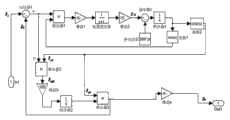
改进型锁相环系统的输入信号e由输入信号Ii和系统输出信号Io的差组成,经过乘法器1、增益1、低通滤波器、增益2,得到信号I1l,I1l与设置的参考频率(500×3.14)进行比较后的差值经过积分器1输出,输出信号经过相移,移相90°,得到移相信号Ip2;The input signal e of the improved phase-locked loop system is composed of the difference between the input signal Ii and the system output signal Io , after
⑵幅值调整⑵Amplitude adjustment
幅值调整部分由乘法器2、增益3、积分器2以及乘法器3组成;移相信号Ip2作为乘法器2的输入,乘法器2输出信号Im2经过增益3放大后,输入到积分器2中,与Ip2一起输入到乘法器3中,乘法器3的输出信号即为改进型锁相环的输出信号表示为Io;The amplitude adjustment part is composed of
将上述改进型锁相环接入到配电网首段的三相零序电流互感器上,则锁相环输出为各条线路的零序电流五次谐波分量;The above-mentioned improved phase-locked loop is connected to the three-phase zero-sequence current transformer in the first section of the distribution network, and the output of the phase-locked loop is the fifth harmonic component of the zero-sequence current of each line;
2.数据处理并选线2. Data processing and line selection
假设各条线路经锁相环输出的信号分别为Io1、Io2、Io3......,在时间T内对它们分别进行n个点采样,得到以下数组:Assuming that the signals output by each line through the phase-locked loop are Io1 , Io2 , Io3 ......, they are respectively sampled at n points within the time T, and the following array is obtained:
I01'=[a1 a2 a3 ... an]I01 '=[a1 a2 a3 ... an ]
I02'=[b1 b2 b3 ... bn]I02 '=[b1 b2 b3 ... bn ]
I03'=[c1 c2 c3 ... cn]I03 '=[c1 c2 c3 ... cn ]
...... …
I01'、I02'、I03'...为采样后得到的数组;I01 ', I02 ', I03 '... are arrays obtained after sampling;
a1,a2,a3,...,an为Io1进行n个点采样后的值;a1 ,a2 ,a3 ,...,an are the values of Io1 after sampling n points;
b1,b2,b3,...,bn为Io2进行n个点采样后的值;b1 ,b2 ,b3 ,...,bn are the values of Io2 after sampling n points;
c1,c2,c3,...,cn为Io3进行n个点采样后的值;c1 ,c2 ,c3 ,...,cn are the values of Io3 after sampling n points;
n为T时间内的采样点数;n is the number of sampling points in T time;
由故障后线路零序电流特征知:非故障线路的谐波零序电流大小为该线路三相对地电容电流的向量和,方向由母线流向线路;故障线路的零序电流等于所有非故障线路零序电流的向量和,方向为由线路流向母线;故障线路和非故障线路的零序电流相位相差180°;According to the characteristics of the zero-sequence current of the line after the fault: the magnitude of the harmonic zero-sequence current of the non-faulted line is the vector sum of the three phase-to-ground capacitance currents of the line, and the direction flows from the bus to the line; the zero-sequence current of the faulty line is equal to the zero-sequence current of all non-faulty lines The vector sum of the sequence current, the direction is from the line to the bus; the phase difference of the zero-sequence current of the faulty line and the non-faulty line is 180°;
设任一线路x发生接地故障:Suppose a ground fault occurs on any line x:
⑴相位比较(1) Phase comparison
线路x经锁相环输出的信号为Iox,在时间T内对它进行n个点采样后得:The signal output by the line x through the phase-locked loop is Iox , and it is sampled at n points within the time T:
I0x'=[x1x2x3...xn]I0x '=[x1 x2 x3 ... xn ]
x1,x2,x3,...,xn为Iox进行n个点采样后的值;x1 , x2 , x3 ,..., xn are the values of Iox after sampling n points;
对各出线数据采集后所得到的数组分别进行两两相乘,即I0i'×I0j'(i、j表示线路号,i=1,2,…,j=1,2,…,i<j)。Multiply the arrays obtained after the data collection of each outgoing line, that is, I0i '×I0j ' (i, j represent line numbers, i=1,2,...,j=1,2,...,i <j).
由于I0x'与I0i'(i表示线路号,i=1,2,…,i≠x)相乘所得新数组中的数据均小于等于零。这表明,Iox的相位与其余电流信号的相位相反,可初步判断线路x存在故障。Since the data in the new array obtained by multiplying I0x ' and I0i ' (i represents the line number, i=1,2,..., i≠x) is less than or equal to zero. This shows that the phase of Iox is opposite to that of other current signals, and it can be preliminarily judged that there is a fault in line x.
⑵幅值比较⑵Amplitude comparison
对以上采样得到的所有数组取绝对值并求和,得到数据I01'',I02'',I03''......Take the absolute value of all the arrays obtained from the above sampling and sum them up to get the data I01 '', I02 '', I03 ''...
I01''=a1'+a2'+a3'+...+an'I01 ''=a1 '+a2 '+a3 '+...+an '
I02''=b1'+b2'+b3'+...+bn'I02 ''=b1 '+b2 '+b3 '+...+bn '
I03''=c1'+c2'+c3'+...+cn'I03 ''=c1 '+c2 '+c3 '+...+cn '
...... …
I0x''=x1'+x2'+x3'+...+xn'I0x ''=x1 '+x2 '+x3 '+...+xn '
a1',a2',a3',...,an'为Io1进行n个点采样并取模后的值;a1 ', a2 ', a3 ',..., an ' are the values after sampling n points of Io1 and taking the modulus;
b1',b2',b3',...,bn'为Io2进行n个点采样并取模后的值;b1 ', b2 ', b3 ',..., bn 'is the value after sampling n points of Io2 and taking the modulus;
c1',c2',c3',...,cn'为Io3进行n个点采样并取模后的值;c1 ', c2 ', c3 ',..., cn ' are the values after n points are sampled and moduloed for Io3 ;
x1',x2',x3',...,xn'为Iox进行n个点采样并取模后的值;x1 ', x2 ', x3 ',..., xn ' is the value after sampling n points and taking the modulus for Iox ;
由上述提到的故障后线路零序电流特征有:The characteristics of the zero-sequence current of the line after the fault mentioned above are:
I0x''=I01''+I02''+I03''+... (1)I0x ''=I01 ''+I02 ''+I03 ''+... (1)
I0x''/n=(I01''+I02''+I03''+...)/n=(I01''/n+I02''/n+I03''/n+...) (2)I0x ''/n=(I01 ''+I02 ''+I03 ''+...)/n=(I01 ''/n+I02 ''/n+I03 ''/ n+...) (2)
由平方和公式容易得到:It is easy to get from the sum of squares formula:
(I0x''/n)2≥(I01''/n)2+(I02''/n)2+(I03''/n)2+... (3)(I0x ''/n)2 ≥ (I01 ''/n)2 +(I02 ''/n)2 +(I03 ''/n)2 +... (3)
这样,不仅获得了各线路的零序电流模平均值,而且经过平方后,各线路数据值差值变大,更利于选线。In this way, not only the zero-sequence current modulus average value of each line is obtained, but also the data value difference of each line becomes larger after square, which is more conducive to line selection.
通过以上分析可知,如果某一线路处理后的数据值大于或等于其余线路处理后数据之和,则该线路存在故障。From the above analysis, it can be seen that if the processed data value of a certain line is greater than or equal to the sum of the processed data of other lines, then there is a fault in this line.
本发明的积极效果:实现间歇性电弧接地故障后零序电流5次谐波电流幅值和相位信息的准确提取,并依托配电网故障特性,实现准确的故障线路选择。The positive effect of the present invention is to realize accurate extraction of zero-sequence current 5th harmonic current amplitude and phase information after intermittent arc grounding faults, and to realize accurate fault line selection based on distribution network fault characteristics.
附图说明Description of drawings
图1是改进型锁相环结构图。Figure 1 is a structural diagram of the improved phase-locked loop.
图2是配电网基本模型结构图。Figure 2 is a structural diagram of the basic model of the distribution network.
图3是三相交流电源参数设置图。Fig. 3 is a parameter setting diagram of a three-phase AC power supply.
图4是三相变压器1参数设置图。Fig. 4 is a parameter setting diagram of the three-
图5是输电线路1参数设置图。FIG. 5 is a parameter setting diagram of the
图6是三相变压器2-1参数设置图。Fig. 6 is a parameter setting diagram of the three-phase transformer 2-1.
图7是负载1参数设置图。Figure 7 is a diagram of
图8是测量模块1参数设置图。FIG. 8 is a parameter setting diagram of the
图9是零序电流信号获取模块图。Fig. 9 is a block diagram of zero-sequence current signal acquisition.
图10是故障模块参数设置图。Figure 10 is a parameter setting diagram of the fault module.
图11是积分器1参数设置图。Fig. 11 is a parameter setting diagram of
图12是锁相环放置到输电线路中的图。Figure 12 is a diagram of a phase locked loop placed in a power transmission line.
图13是示波器1参数设置图。Figure 13 is a parameter setting diagram of the
图14是五个示波器显示的波形图。Figure 14 is a waveform diagram displayed by five oscilloscopes.
具体实施方式Detailed ways
下面将以线路1发生间歇性电弧接地故障时实现选线的过程为例对具体实施方式进行说明。The specific implementation will be described below by taking the line selection process when an intermittent arc-to-ground fault occurs on the
1.使用计算机中矩阵实验室软件Matlab的可视化仿真工具Simulink进行仿真模型的搭建:1. Use the visual simulation tool Simulink of the matrix laboratory software Matlab in the computer to build the simulation model:
(1)搭建10.5KV配电网基本模型(1) Build the basic model of 10.5KV distribution network
基本模型结构图如图2所示,包括三相交流电源、变压器、消弧线圈、输电线路、负载、电流互感器,设置各元件参数如下:The basic model structure diagram is shown in Figure 2, including three-phase AC power supply, transformer, arc suppression coil, transmission line, load, and current transformer. The parameters of each component are set as follows:
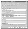
三相交流电源:相间电压有效值(Phase-to-phase rms voltage):60e3;A相初始相位(Phase angle of phase A):0;频率(Frequency):50Hz;中性点接地方式(Inter connection):Yg;容量(3-phase short-circuit level at base voltage):500MVA;基本电压(Base voltage):60e3;X/R比值(X/R ratio):0.0007。如图3所示。Three-phase AC power supply: Phase-to-phase rms voltage: 60e3 ; Phase angle of phase A: 0; Frequency: 50Hz; Neutral point grounding method (Inter connection): Yg; capacity (3-phase short-circuit level at base voltage): 500MVA; base voltage (Base voltage): 60e3 ; X/R ratio (X/R ratio): 0.0007. As shown in Figure 3.
三相变压器1:额定容量和频率(Nominal power and frequency):[20e3,50];绕组1连接(Winding1connection):Delta(D1);绕组1参数(Winding1parameters):[60e3,0.006675,0.1348];绕组2连接(Winding2connection):Yn;绕组2参数(Winding2parameters):[10.5e3,0.006675,0.1348];磁化电阻(Magnetization resistance Rm):153.846;磁化电感(Magnetization resistanceLm):153.846;测量(Measurement):None。如图4所示。Three-phase transformer 1: rated capacity and frequency (Nominal power and frequency): [20e3 , 50]; winding 1 connection (Winding1connection): Delta (D1); winding 1 parameter (Winding1parameters): [60e3 , 0.006675,0.1348] ;Winding2connection: Yn; Winding2parameters: [10.5e3 , 0.006675,0.1348]; Magnetization resistance Rm: 153.846; Magnetization inductance (Magnetization resistanceLm): 153.846; Measurement : None. As shown in Figure 4.
消弧线圈:电感:5.6H。Arc suppression coil: Inductance: 5.6H.
输电线路:模型中共有5条10kV输电线路1~5,均采用“Three-phase PI SectionLine”模型,长度顺次为:10km、12km、8km、13km、11km;线路参数设置均相同,线路1参数设置如下:Transmission lines: There are five
相数(Number of phases N):3;频率(Frequency used for R L C specification):50;单位长度电阻(Resistance per unit length):[0.4018,0.5497];单位长度电感(Inductance per unit length):[1.116e-3,4.074e-3];单位长度电容(Capacitance per unit length):[1.0428e-8,1.3474e-8];线路长度(Line length):10;测量(Measurement):None。如图5所示;Number of phases N: 3; Frequency used for R L C specification: 50; Resistance per unit length: [0.4018,0.5497]; Inductance per unit length: [1.116 e-3 , 4.074e-3 ]; Capacitance per unit length: [1.0428e-8 , 1.3474e-8 ]; Line length: 10; Measurement: None. As shown in Figure 5;
三相变压器2:模型中共有5个三相变压器2,依次为三相变压器2-1、三相变压器2-2、三相变压器2-3、三相变压器2-4、三相变压器2-5,它们的参数设置均相同,三相变压器2-1参数设置如下:Three-phase transformer 2: There are 5 three-
额定容量和频率(Nominal power and frequency):[4748e3,50];绕组1连接(Winding1connection):Y;绕组1参数(Winding1parameters):[10e3,0.024032224,0.054976833];绕组2连接(Winding2connection):Yg;绕组2参数(Winding2parameters):[380,0.024032224,0.054976833];磁化电阻(Magnetization resistance Rm):5712.08585;磁化电感(Magnetizationresistance Lm):5712.08585;测量(Measurement):None。如图6所示。Rated capacity and frequency (Nominal power and frequency): [4748e3 , 50]; Winding 1 connection (Winding1connection): Y;
负载:模型中共有5个负载1~5,均采用“parallel RLC load”模型,它们的以下参数设置相同,负载1参数设置如下:Load: There are 5
配置(Configuration):Y;额定相电压(Nominal phase-to-phase voltage Vn):380;额定频率(Nominal frequency fn):50;感性无功(Inductive reactive powerQL):2400Var;容性无功(Capacitive reactive power Qc):0。Configuration: Y; Nominal phase-to-phase voltage Vn: 380; Nominal frequency fn: 50; Inductive reactive powerQL: 2400Var; reactive power Qc): 0.
五个负载的有功负荷(Active power P)依次为:2360W,2510W,2510W,2523W,2523W。如图7所示。The active power loads (Active power P) of the five loads are: 2360W, 2510W, 2510W, 2523W, 2523W. As shown in Figure 7.
电流互感器:在线路1~5的每条线路始端都放置一个三相电压电流测量模块1~5,参数设置如下:Current transformer: Place a three-phase voltage and
电压测量(Voltage measurement):phase-to-ground;电流测量(Currentmeasurement):yes。Voltage measurement: phase-to-ground; Current measurement: yes.
如图8所示;As shown in Figure 8;
零序电流信号处理:在测量模块1~5的电流输出口,均采用如图9所示的方式获得并处理零序电流信号,其中增益=1/3;Zero-sequence current signal processing: At the current output ports of
上述元件参数设置完成后,按图2所示电路依次连接各元件:三相交流电源的输出是三相变压器1的输入,三相变压器1的输出通过各线路的测量模块与各输电线路相连,各输电线路通过各线路中的三相变压器2与各线路负载相连。三相变压器的中性点与消弧线圈相连后接地。各测量模块的电流输出接各零线电流信号处理模块。After the parameter setting of the above components is completed, connect the components in sequence according to the circuit shown in Figure 2: the output of the three-phase AC power supply is the input of the three-
(2)故障设置(2) Fault setting
假设在输电线路1的A相4km处,6.066s~6.156s之间发生5次电弧接地故障,接地电阻为5欧。使用Three-Phase Fault模块进行故障设置,具体参数如下:Assume that 5 arc-to-ground faults occur between 6.066s and 6.156s at a distance of 4km from phase A of
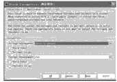
参数(Parameters):选择Phase A Fault;故障电阻(Fault resistance):5;接地电阻(Ground resistance):5;转换状态(Transition status):[1010101010];转换时间(Transition times):[6.0666.0766.0866.0966.1066.1166.1266.1366.1466.156];过渡电阻(Snubbers resistance Rp):1e6;过渡电容(Snubbers resistance Cp):inf;测量(Measurement):None。如图10所示。将设置后的故障模块连接到输电线路1中,故障模块前的线路长度为9km。Parameters: Select Phase A Fault; Fault resistance: 5; Ground resistance: 5; Transition status: [1010101010]; Transition times: [6.0666.0766.0866 .0966.1066.1166.1266.1366.1466.156]; transition resistance (Snubbers resistance Rp): 1e6 ; transition capacitance (Snubbers resistance Cp): inf; measurement (Measurement): None. As shown in Figure 10. Connect the set fault module to
(3)搭建改进型锁相环模型(3) Building an improved phase-locked loop model
基本模型如图1所示,包括加法器、乘法器、增益、低通滤波器、常量、积分器、函数,设置各元件参数如下:The basic model is shown in Figure 1, including adder, multiplier, gain, low-pass filter, constant, integrator, and function. The parameters of each component are set as follows:
加法器1:设置加法器1为两个输入端口,分别为+、-,如图1中所示;Adder 1: set
增益1:增益大小设置为2.4315;Gain 1: set the gain size to 2.4315;
低通滤波器:分子系数设置为[1],分母系数设置为[11],绝对容差设置为auto;Low-pass filter: the numerator coefficient is set to [1], the denominator coefficient is set to [11], and the absolute tolerance is set to auto;
增益2:增益大小设置为10;Gain 2: set the gain size to 10;
加法器2:设置加法器2为两个输入端口,分别为+、-。如图1中所示;Adder 2: Set
参考频率:参考频率设置为500*pi;Reference frequency: The reference frequency is set to 500*pi;
积分器1、2:设置参数如下:外部复位(External reset):none;初始条件来源(Initial conditionsource):internal;初始条件(Initial condition):0;上饱和限制(Uppersaturation limit):inf;下饱和限制(Lower saturation limit):-inf;绝对容差(Absolute tolerance):auto。如图11所示;
函数1:表达式设置为sin(u),采样时间设置为-1;Function 1: The expression is set to sin(u), and the sampling time is set to -1;
函数2:表达式设置为cos(u),采样时间设置为-1;Function 2: The expression is set to cos(u), and the sampling time is set to -1;
增益3:增益大小设置为100;Gain 3: set the gain size to 100;
增益4:增益大小设置为0.93;Gain 4: set the gain size to 0.93;
上述元件参数设置完成后,按图1所示电路依次连接各元件:外部输入信号与乘法器3的输出信号通过加法器1做差,加法器1的输出分别是乘法器1和乘法器2的一个输入。函数1的输出是乘法器1的另一个输入,乘法器1的输出是增益1的输入。增益1的输出是低通滤波器的输入。低通滤波器的输出是增益2的输入,增益2的输出与参考频率的输出通过加法器2做差,加法器2的输出是积分器1的输入,积分器1的输出分别是函数1和函数2的输入。函数2的输出是乘法器2的另一个输入和乘法器3的一个输入,乘法器2的输出是增益3的输入。增益3的输出是积分器2的输入,积分器2的输出是乘法器3的另一个输入。乘法器3的输出是加法器1的一个输入和增益4的输入。增益4的输出是锁相环模块的输出。After the parameter setting of the above components is completed, connect the components in sequence according to the circuit shown in Figure 1: the external input signal and the output signal of the
锁相环模块搭建完毕后,对其创建子模块。复制出五个相同的锁相环子模块,并依次命名为锁相环1~5,然后将五个锁相环子模块分别连接到各线路的零序电流信号处理模块和示波器之间。如图12所示。After the phase-locked loop module is built, create sub-modules for it. Copy five identical phase-locked loop sub-modules, and name them sequentially as phase-locked loop 1-5, and then connect the five phase-locked loop sub-modules to the zero-sequence current signal processing module of each line and the oscilloscope. As shown in Figure 12.
2.信号提取2. Signal extraction
仿真模型搭建完毕后,即可利用改进型锁相环进行零序电流五次谐波分量的提取:After the simulation model is built, the improved phase-locked loop can be used to extract the fifth harmonic component of the zero-sequence current:
⑴相位调整⑴Phase adjustment
改进型锁相环系统的输入信号由外部输入信号和乘法器3的输出信号的差组成,经过乘法器1、增益1、低通滤波器、增益2,得到的信号与设置的参考频率(500×3.14)进行比较后的差值经过积分器1输出,输出信号经过相移,移相90°,得到移相信号。The input signal of the improved phase-locked loop system is composed of the difference between the external input signal and the output signal of
⑵幅值调整⑵Amplitude adjustment
幅值调整部分由乘法器2、增益3、积分器2以及乘法器3组成。移相信号作为乘法器2的输入,乘法器2输出信号经过增益3放大后,输入到积分器2中,与移相信号一起输入到乘法器3中,乘法器3的输出信号即为改进型锁相环的输出信号,也就是各条线路的零序电流五次谐波分量。The amplitude adjustment part is composed of
3.显示模块与数据处理3. Display module and data processing
将五个锁相环的输出口1依次连接示波器1~5,示波器参数设置均如下:Connect the
坐标数(Number of axes):1;定时范围(Timer range):auto;刻度标记(Ticklabel):bottom axis only;采样(Sampling):Sample time,0.0002。如图13所示。对数据进行保存,数据依次命名为L01,L02,L03,L04,L05,格式为:Array。Number of axes: 1; Timer range: auto; Ticklabel: bottom axis only; Sampling: Sample time, 0.0002. As shown in Figure 13. Save the data, the data are named L01 , L02 , L03 , L04 , L05 in sequence, and the format is: Array.
五个示波器显示的波形依次如图14所示。The waveforms displayed by the five oscilloscopes are shown in Figure 14 in turn.
⑴相位比较(1) Phase comparison
对L01,L02,L03,L04,L05的6.0662s~6.086s时间内的100个数据进行提取,得到的数组依次为:Extract 100 data from L01 , L02 , L03 , L04 , and L05 within the time period of 6.0662s to 6.086s, and the obtained arrays are as follows:
L01'、L02'、L03'、L04'、L05'L01 ', L02 ', L03 ', L04 ', L05 '
将此五个数组进行两两相乘,即L01'×L02'、L01'×L03'、L01'×L04'、L01'×L05'、L02'×L03'、L02'×L04'、L02'×L05'、L03'×L04'、L03'×L05'、L04'×L05'。计算后知,数组L01’与其它数组相乘后得到的新数组中的数均小于等于零,可初步判断线路1发生故障。Multiply these five arrays two by two, that is, L01 '×L02 ', L01 '×L03 ', L01 '×L04 ', L01 '×L05 ', L02 '×L03 ', L02 '×L04 ', L02 '×L05 ', L03 '×L04 ', L03 '×L05 ', L04 '×L05 '. After the calculation, it is known that the numbers in the new array obtained by multiplying the array L01 ' with other arrays are all less than or equal to zero, and it can be preliminarily judged that the
⑵幅值比较⑵Amplitude comparison
对L01,L02,L03,L04,L05的6.0662s~6.086s时间内的100个数据进行取绝对值、平均值、平方、扩大1000倍处理(注:由于此处采集的数据较小,因此选择将得到的数据进行扩大1000倍。实际应用中,应根据实际数据情况选择合适的扩大倍数):100 data of L01 , L02 , L03 , L04 , and L05 within 6.0662s ~ 6.086s are processed by taking absolute value, average value, square, and expanding 1000 times (note: due to the data collected here Smaller, so choose to expand the obtained data by 1000 times. In practical applications, you should choose an appropriate expansion factor according to the actual data situation):
L01''=a1'+a2'+a3'+...+a100'=5.930L01 ''=a1 '+a2 '+a3 '+...+a100 '=5.930
L02''=b1'+b2'+b3'+...+b100'=1.649L02 ''=b1 '+b2 '+b3 '+...+b100 '=1.649
L03''=c1'+c2'+c3'+...+c100'=1.091L03 ''=c1 '+c2 '+c3 '+...+c100 '=1.091
L04''=d1'+d2'+d3'+...+d100'=1.921L04 ''=d1 '+d2 '+d3 '+...+d100 '=1.921
L05''=e1'+e2'+e3'+...+e100'=1.619L05 ''=e1 '+e2 '+e3 '+...+e100 '=1.619
由式Li=(L0i''÷100)2×1000(i=1,2,3,4,5)可计算出L1、L2、L3、L4、L5如表1所示。From the formula Li =(L0i ''÷100)2 ×1000 (i=1,2,3,4,5) can calculate L1 , L2 , L3 , L4 , L5 as shown in Table 1 Show.
表1Table 1
4.故障选线4. Fault line selection
显然,从图15可得到配电线路1的五次谐波零序电流相位与其余线路的相反。从表1可得到,配电线路1的电流处理值L1=3.517大于L2+L3+L4+L5=1.022。根据以上获得的相位和幅值比较信息可以知道,配电线路1确实发生故障。Obviously, it can be obtained from Fig. 15 that the phase of the fifth harmonic zero-sequence current of
以上实例中的故障,发生在相电压为零值的时刻。对于相电压为其他值时发生故障的情况,本文也做了仿真。结果表明,此方法依然可以实现准确选线。The fault in the above example occurs when the phase voltage is zero. For the situation that the fault occurs when the phase voltage is other values, this paper also makes a simulation. The results show that this method can still achieve accurate line selection.
本发明利用改进型锁相环对经消弧线圈补偿后的故障电流五次谐波分量进行了提取。理论分析和仿真实验都表明:利用改进型锁相环提取的五次谐波零序电流信号能够在短时间内实现故障选线。The invention uses the improved phase-locked loop to extract the fifth harmonic component of the fault current compensated by the arc suppression coil. Both theoretical analysis and simulation experiments show that the fault line selection can be realized in a short time by using the fifth harmonic zero-sequence current signal extracted by the improved phase-locked loop.
Claims (1)
Translated fromChinesePriority Applications (1)
| Application Number | Priority Date | Filing Date | Title |
|---|---|---|---|
| CN201310174874.4ACN103308821B (en) | 2013-05-13 | 2013-05-13 | Intermittent arcing ground-fault line selection method based on improved phase locked loop |
Applications Claiming Priority (1)
| Application Number | Priority Date | Filing Date | Title |
|---|---|---|---|
| CN201310174874.4ACN103308821B (en) | 2013-05-13 | 2013-05-13 | Intermittent arcing ground-fault line selection method based on improved phase locked loop |
Publications (2)
| Publication Number | Publication Date |
|---|---|
| CN103308821Atrue CN103308821A (en) | 2013-09-18 |
| CN103308821B CN103308821B (en) | 2015-07-01 |
Family
ID=49134252
Family Applications (1)
| Application Number | Title | Priority Date | Filing Date |
|---|---|---|---|
| CN201310174874.4AExpired - Fee RelatedCN103308821B (en) | 2013-05-13 | 2013-05-13 | Intermittent arcing ground-fault line selection method based on improved phase locked loop |
Country Status (1)
| Country | Link |
|---|---|
| CN (1) | CN103308821B (en) |
Cited By (6)
| Publication number | Priority date | Publication date | Assignee | Title |
|---|---|---|---|---|
| CN107272645A (en)* | 2017-06-28 | 2017-10-20 | 中国能源建设集团甘肃省电力设计院有限公司 | The photovoltaic electric station grid connection fault model and analysis method of Neutral Grounding through Resistance in Electrical |
| CN107367670A (en)* | 2017-08-16 | 2017-11-21 | 杭州零尔电力科技有限公司 | A kind of fault line selection method for single-phase-to-ground fault based on quintuple harmonics electric current |
| CN109596873A (en)* | 2018-12-05 | 2019-04-09 | 合肥能安科技有限公司 | A kind of intelligent electric meter with warning function |
| CN111398759A (en)* | 2020-04-29 | 2020-07-10 | 威胜集团有限公司 | Signal compensation method, device and storage medium |
| CN113447850A (en)* | 2021-08-13 | 2021-09-28 | 南通通明集团有限公司 | Intermittent arc grounding fault line selection method for small-current grounding system |
| CN114545288A (en)* | 2021-12-29 | 2022-05-27 | 国网安徽省电力有限公司阜阳供电公司 | Distribution cable arc light grounding fault determination method and system based on harmonic component |
Citations (4)
| Publication number | Priority date | Publication date | Assignee | Title |
|---|---|---|---|---|
| JP2001091595A (en)* | 1999-09-28 | 2001-04-06 | Matsushita Electric Ind Co Ltd | LSI semiconductor inspection device and semiconductor device |
| JP2008249481A (en)* | 2007-03-30 | 2008-10-16 | Nec Electronics Corp | Semiconductor device with pll circuit |
| CN101453187A (en)* | 2008-12-29 | 2009-06-10 | 浙江大学 | Wind turbine control reference signal detection method for unsymmetrical failure of electric grid |
| CN102859334A (en)* | 2010-03-24 | 2013-01-02 | 魁北克水电公司 | Method And System For The Time Synchronization Of The Phase Of Signals From Respective Measurement Devices |
- 2013
- 2013-05-13CNCN201310174874.4Apatent/CN103308821B/ennot_activeExpired - Fee Related
Patent Citations (4)
| Publication number | Priority date | Publication date | Assignee | Title |
|---|---|---|---|---|
| JP2001091595A (en)* | 1999-09-28 | 2001-04-06 | Matsushita Electric Ind Co Ltd | LSI semiconductor inspection device and semiconductor device |
| JP2008249481A (en)* | 2007-03-30 | 2008-10-16 | Nec Electronics Corp | Semiconductor device with pll circuit |
| CN101453187A (en)* | 2008-12-29 | 2009-06-10 | 浙江大学 | Wind turbine control reference signal detection method for unsymmetrical failure of electric grid |
| CN102859334A (en)* | 2010-03-24 | 2013-01-02 | 魁北克水电公司 | Method And System For The Time Synchronization Of The Phase Of Signals From Respective Measurement Devices |
Non-Patent Citations (2)
| Title |
|---|
| 张志霞 等: "一种应用于电力系统的锁相环", 《电工技术学报》, vol. 27, no. 2, 29 February 2012 (2012-02-29)* |
| 张志霞 等: "农村配电网间歇性电弧接地故障选线研究", 《沈阳农业大学学报》, vol. 43, no. 5, 31 October 2012 (2012-10-31), pages 623 - 625* |
Cited By (9)
| Publication number | Priority date | Publication date | Assignee | Title |
|---|---|---|---|---|
| CN107272645A (en)* | 2017-06-28 | 2017-10-20 | 中国能源建设集团甘肃省电力设计院有限公司 | The photovoltaic electric station grid connection fault model and analysis method of Neutral Grounding through Resistance in Electrical |
| CN107272645B (en)* | 2017-06-28 | 2019-08-02 | 中国能源建设集团甘肃省电力设计院有限公司 | The photovoltaic electric station grid connection fault model and analysis method of Neutral Grounding through Resistance in Electrical |
| CN107367670A (en)* | 2017-08-16 | 2017-11-21 | 杭州零尔电力科技有限公司 | A kind of fault line selection method for single-phase-to-ground fault based on quintuple harmonics electric current |
| CN109596873A (en)* | 2018-12-05 | 2019-04-09 | 合肥能安科技有限公司 | A kind of intelligent electric meter with warning function |
| CN109596873B (en)* | 2018-12-05 | 2021-04-20 | 合肥能安科技有限公司 | Smart electric meter with early warning function |
| CN111398759A (en)* | 2020-04-29 | 2020-07-10 | 威胜集团有限公司 | Signal compensation method, device and storage medium |
| CN113447850A (en)* | 2021-08-13 | 2021-09-28 | 南通通明集团有限公司 | Intermittent arc grounding fault line selection method for small-current grounding system |
| CN114545288A (en)* | 2021-12-29 | 2022-05-27 | 国网安徽省电力有限公司阜阳供电公司 | Distribution cable arc light grounding fault determination method and system based on harmonic component |
| CN114545288B (en)* | 2021-12-29 | 2025-01-28 | 国网安徽省电力有限公司阜阳供电公司 | A method and system for determining arc grounding fault of distribution cable based on harmonic components |
Also Published As
| Publication number | Publication date |
|---|---|
| CN103308821B (en) | 2015-07-01 |
Similar Documents
| Publication | Publication Date | Title |
|---|---|---|
| CN105071405B (en) | Micro-grid system with unbalanced nonlinear loads and Power balance control method | |
| CN103792465B (en) | A kind of method of the range finding of the one-phase earthing failure in electric distribution network based on residual voltage | |
| CN103308821B (en) | Intermittent arcing ground-fault line selection method based on improved phase locked loop | |
| CN107329044B (en) | A single-phase-to-ground fault line selection method in distribution network based on arc transient component | |
| CN105515003A (en) | Active power filter for detecting harmonic wave and wattless current and detecting method thereof | |
| CN108879775B (en) | A Coordinated Control Method of Grid Unbalanced Photovoltaic Inverter Considering Current Limit | |
| CN103226176A (en) | Line selection method for single-phase earth fault of power distribution network | |
| CN107332227A (en) | The singlephase earth fault voltage arc extinguishing method and system of isolated neutral system | |
| CN103063984A (en) | Power distribution network single-phase earth fault line selection method based on line double-terminal negative sequence current | |
| Liang et al. | A single-phase-to-ground fault detection method based on the ratio fluctuation coefficient of the zero-sequence current and voltage differential in a distribution network | |
| CN102253266A (en) | Three-phase four-wire system harmonic current detection method based on linear filter | |
| CN103269086A (en) | Positive and negative sequence component separation method for low voltage ride through control of photovoltaic grid-connected inverter | |
| CN102680861A (en) | System and method for testing short circuit withstanding capability of transformer or electric reactor | |
| CN105954640A (en) | Power distribution network fault line selection method based on dominant frequency zero sequence power | |
| CN103472348A (en) | Instantaneous-power-based single phase ground fault line selection method of resonant grounded system | |
| CN104898029A (en) | Similarity single-phase earth fault line selection method based on active full compensation arc suppression control | |
| CN106093591A (en) | A kind of isolated neutral capacitance current of distribution network measures system and method | |
| CN105116251A (en) | Transformer fault discrimination and protection method | |
| CN104734537B (en) | A kind of wind-powered electricity generation converter Control method being controlled based on positive-negative sequence current internal ring | |
| Tao et al. | An advanced islanding detection strategy coordinating the newly proposed v detection and the rocof detection | |
| CN119001336A (en) | Fault phase selection method, device, equipment and medium based on LCL filter | |
| CN103701096B (en) | A kind of inter-turn protection method of the controlled height of TCT formula anti-triangle junction winding | |
| Win et al. | Constant DC capacitor voltage control based strategy for active load balancer in three-phase four-wire distribution system | |
| CN109245116A (en) | A kind of power capacitor inrush phenomenon inhibition device and method | |
| CN105356499B (en) | The control method of grid stimulating device |
Legal Events
| Date | Code | Title | Description |
|---|---|---|---|
| C06 | Publication | ||
| PB01 | Publication | ||
| C10 | Entry into substantive examination | ||
| SE01 | Entry into force of request for substantive examination | ||
| C14 | Grant of patent or utility model | ||
| GR01 | Patent grant | ||
| CF01 | Termination of patent right due to non-payment of annual fee | ||
| CF01 | Termination of patent right due to non-payment of annual fee | Granted publication date:20150701 Termination date:20210513 |