CN103307658A - Heat exchanger and machine cabinet - Google Patents
Heat exchanger and machine cabinetDownload PDFInfo
- Publication number
- CN103307658A CN103307658ACN2012100651569ACN201210065156ACN103307658ACN 103307658 ACN103307658 ACN 103307658ACN 2012100651569 ACN2012100651569 ACN 2012100651569ACN 201210065156 ACN201210065156 ACN 201210065156ACN 103307658 ACN103307658 ACN 103307658A
- Authority
- CN
- China
- Prior art keywords
- heat exchanger
- compressor
- heat
- valve
- pipeline
- Prior art date
- Legal status (The legal status is an assumption and is not a legal conclusion. Google has not performed a legal analysis and makes no representation as to the accuracy of the status listed.)
- Pending
Links
Images


Classifications
- H—ELECTRICITY
- H05—ELECTRIC TECHNIQUES NOT OTHERWISE PROVIDED FOR
- H05K—PRINTED CIRCUITS; CASINGS OR CONSTRUCTIONAL DETAILS OF ELECTRIC APPARATUS; MANUFACTURE OF ASSEMBLAGES OF ELECTRICAL COMPONENTS
- H05K7/00—Constructional details common to different types of electric apparatus
- H05K7/20—Modifications to facilitate cooling, ventilating, or heating
- H05K7/20536—Modifications to facilitate cooling, ventilating, or heating for racks or cabinets of standardised dimensions, e.g. electronic racks for aircraft or telecommunication equipment
- H05K7/207—Thermal management, e.g. cabinet temperature control
- F—MECHANICAL ENGINEERING; LIGHTING; HEATING; WEAPONS; BLASTING
- F28—HEAT EXCHANGE IN GENERAL
- F28D—HEAT-EXCHANGE APPARATUS, NOT PROVIDED FOR IN ANOTHER SUBCLASS, IN WHICH THE HEAT-EXCHANGE MEDIA DO NOT COME INTO DIRECT CONTACT
- F28D15/00—Heat-exchange apparatus with the intermediate heat-transfer medium in closed tubes passing into or through the conduit walls ; Heat-exchange apparatus employing intermediate heat-transfer medium or bodies
- F28D15/02—Heat-exchange apparatus with the intermediate heat-transfer medium in closed tubes passing into or through the conduit walls ; Heat-exchange apparatus employing intermediate heat-transfer medium or bodies in which the medium condenses and evaporates, e.g. heat pipes
- F28D15/0266—Heat-exchange apparatus with the intermediate heat-transfer medium in closed tubes passing into or through the conduit walls ; Heat-exchange apparatus employing intermediate heat-transfer medium or bodies in which the medium condenses and evaporates, e.g. heat pipes with separate evaporating and condensing chambers connected by at least one conduit; Loop-type heat pipes; with multiple or common evaporating or condensing chambers
- F—MECHANICAL ENGINEERING; LIGHTING; HEATING; WEAPONS; BLASTING
- F28—HEAT EXCHANGE IN GENERAL
- F28D—HEAT-EXCHANGE APPARATUS, NOT PROVIDED FOR IN ANOTHER SUBCLASS, IN WHICH THE HEAT-EXCHANGE MEDIA DO NOT COME INTO DIRECT CONTACT
- F28D15/00—Heat-exchange apparatus with the intermediate heat-transfer medium in closed tubes passing into or through the conduit walls ; Heat-exchange apparatus employing intermediate heat-transfer medium or bodies
- F28D15/02—Heat-exchange apparatus with the intermediate heat-transfer medium in closed tubes passing into or through the conduit walls ; Heat-exchange apparatus employing intermediate heat-transfer medium or bodies in which the medium condenses and evaporates, e.g. heat pipes
- F28D15/06—Control arrangements therefor
- F—MECHANICAL ENGINEERING; LIGHTING; HEATING; WEAPONS; BLASTING
- F28—HEAT EXCHANGE IN GENERAL
- F28F—DETAILS OF HEAT-EXCHANGE AND HEAT-TRANSFER APPARATUS, OF GENERAL APPLICATION
- F28F27/00—Control arrangements or safety devices specially adapted for heat-exchange or heat-transfer apparatus
- H—ELECTRICITY
- H05—ELECTRIC TECHNIQUES NOT OTHERWISE PROVIDED FOR
- H05K—PRINTED CIRCUITS; CASINGS OR CONSTRUCTIONAL DETAILS OF ELECTRIC APPARATUS; MANUFACTURE OF ASSEMBLAGES OF ELECTRICAL COMPONENTS
- H05K7/00—Constructional details common to different types of electric apparatus
- H05K7/20—Modifications to facilitate cooling, ventilating, or heating
- H05K7/20536—Modifications to facilitate cooling, ventilating, or heating for racks or cabinets of standardised dimensions, e.g. electronic racks for aircraft or telecommunication equipment
- H05K7/20609—Air circulating in closed loop within cabinets wherein heat is removed through air-to-liquid heat-exchanger
- F—MECHANICAL ENGINEERING; LIGHTING; HEATING; WEAPONS; BLASTING
- F25—REFRIGERATION OR COOLING; COMBINED HEATING AND REFRIGERATION SYSTEMS; HEAT PUMP SYSTEMS; MANUFACTURE OR STORAGE OF ICE; LIQUEFACTION SOLIDIFICATION OF GASES
- F25B—REFRIGERATION MACHINES, PLANTS OR SYSTEMS; COMBINED HEATING AND REFRIGERATION SYSTEMS; HEAT PUMP SYSTEMS
- F25B1/00—Compression machines, plants or systems with non-reversible cycle
- F—MECHANICAL ENGINEERING; LIGHTING; HEATING; WEAPONS; BLASTING
- F25—REFRIGERATION OR COOLING; COMBINED HEATING AND REFRIGERATION SYSTEMS; HEAT PUMP SYSTEMS; MANUFACTURE OR STORAGE OF ICE; LIQUEFACTION SOLIDIFICATION OF GASES
- F25B—REFRIGERATION MACHINES, PLANTS OR SYSTEMS; COMBINED HEATING AND REFRIGERATION SYSTEMS; HEAT PUMP SYSTEMS
- F25B2600/00—Control issues
- F25B2600/25—Control of valves
- F25B2600/2501—Bypass valves
- F—MECHANICAL ENGINEERING; LIGHTING; HEATING; WEAPONS; BLASTING
- F28—HEAT EXCHANGE IN GENERAL
- F28D—HEAT-EXCHANGE APPARATUS, NOT PROVIDED FOR IN ANOTHER SUBCLASS, IN WHICH THE HEAT-EXCHANGE MEDIA DO NOT COME INTO DIRECT CONTACT
- F28D1/00—Heat-exchange apparatus having stationary conduit assemblies for one heat-exchange medium only, the media being in contact with different sides of the conduit wall, in which the other heat-exchange medium is a large body of fluid, e.g. domestic or motor car radiators
- F28D1/02—Heat-exchange apparatus having stationary conduit assemblies for one heat-exchange medium only, the media being in contact with different sides of the conduit wall, in which the other heat-exchange medium is a large body of fluid, e.g. domestic or motor car radiators with heat-exchange conduits immersed in the body of fluid
- F28D1/04—Heat-exchange apparatus having stationary conduit assemblies for one heat-exchange medium only, the media being in contact with different sides of the conduit wall, in which the other heat-exchange medium is a large body of fluid, e.g. domestic or motor car radiators with heat-exchange conduits immersed in the body of fluid with tubular conduits
- F28D1/053—Heat-exchange apparatus having stationary conduit assemblies for one heat-exchange medium only, the media being in contact with different sides of the conduit wall, in which the other heat-exchange medium is a large body of fluid, e.g. domestic or motor car radiators with heat-exchange conduits immersed in the body of fluid with tubular conduits the conduits being straight
- F28D1/0535—Heat-exchange apparatus having stationary conduit assemblies for one heat-exchange medium only, the media being in contact with different sides of the conduit wall, in which the other heat-exchange medium is a large body of fluid, e.g. domestic or motor car radiators with heat-exchange conduits immersed in the body of fluid with tubular conduits the conduits being straight the conduits having a non-circular cross-section
- F28D1/05366—Assemblies of conduits connected to common headers, e.g. core type radiators
- F—MECHANICAL ENGINEERING; LIGHTING; HEATING; WEAPONS; BLASTING
- F28—HEAT EXCHANGE IN GENERAL
- F28D—HEAT-EXCHANGE APPARATUS, NOT PROVIDED FOR IN ANOTHER SUBCLASS, IN WHICH THE HEAT-EXCHANGE MEDIA DO NOT COME INTO DIRECT CONTACT
- F28D21/00—Heat-exchange apparatus not covered by any of the groups F28D1/00 - F28D20/00
- F28D2021/0019—Other heat exchangers for particular applications; Heat exchange systems not otherwise provided for
- F28D2021/0028—Other heat exchangers for particular applications; Heat exchange systems not otherwise provided for for cooling heat generating elements, e.g. for cooling electronic components or electric devices
- F—MECHANICAL ENGINEERING; LIGHTING; HEATING; WEAPONS; BLASTING
- F28—HEAT EXCHANGE IN GENERAL
- F28D—HEAT-EXCHANGE APPARATUS, NOT PROVIDED FOR IN ANOTHER SUBCLASS, IN WHICH THE HEAT-EXCHANGE MEDIA DO NOT COME INTO DIRECT CONTACT
- F28D21/00—Heat-exchange apparatus not covered by any of the groups F28D1/00 - F28D20/00
- F28D2021/0019—Other heat exchangers for particular applications; Heat exchange systems not otherwise provided for
- F28D2021/0068—Other heat exchangers for particular applications; Heat exchange systems not otherwise provided for for refrigerant cycles
Landscapes
- Engineering & Computer Science (AREA)
- Physics & Mathematics (AREA)
- Thermal Sciences (AREA)
- Mechanical Engineering (AREA)
- General Engineering & Computer Science (AREA)
- Aviation & Aerospace Engineering (AREA)
- Microelectronics & Electronic Packaging (AREA)
- Life Sciences & Earth Sciences (AREA)
- Sustainable Development (AREA)
- Other Air-Conditioning Systems (AREA)
Abstract
Translated fromChineseDescription
Translated fromChinese技术领域technical field
本发明涉及机械和电学技术领域,特别涉及一种热交换器及一种机柜。The invention relates to the technical fields of mechanics and electricity, in particular to a heat exchanger and a cabinet.
背景技术Background technique
各种设备在工作过程中对其环境都有一定的需求,而设备在工作过程中温度过高则会影响其工作效率、可靠性。因此很多设备都需要有热交换器来将设备的热量传导出设备,以实现设备在适宜的温度下工作以保证其工作效率和可靠性。热交换器因此得到了广泛的应用。All kinds of equipment have certain requirements for their environment during the working process, and the high temperature of the equipment during the working process will affect its working efficiency and reliability. Therefore, many devices need a heat exchanger to conduct the heat of the device out of the device, so that the device can work at a suitable temperature to ensure its working efficiency and reliability. Heat exchangers are therefore widely used.
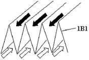
以通信基站为例,大功率机柜的散热通常采用的热交换器可以是:热交换器/换热器(HEX、Heat Exchanger)或者使用空调器的热交换能力来实现散热。通信基站的大功率机柜一般有维持通信设备与外界隔离,以满足通信设备的IP55等级需求,而采用热交换器或者通信机柜空调器形式,在保证散热的同时,可以维持通信设备与外界的隔离,实现设备的IP55等级,以及通信设备内部器件的可靠性要求,如图1A所示,为大功率机柜的散热结构示意图,包括:通信设备机箱1A、热交换器1B,热交换器1B中有隔板1B1隔绝通信设备机箱1A内部和外部的空气;如图1B所示,为换热原理结构示意图。在图1A和图1B中,黑色箭头方向为通信设备机箱1A内的空气流动方向(其中在散热器内的部分称为内循环风道(第一风道300)),白色箭头方向为通信设备机箱1A外部空气流动方向(其中在散热器内的部分称为外循环风道),通信设备机箱1A内外的空气在热交换器1B进行换热;空气流动通过风扇实现内外风道,由隔板(200)分隔的内循环风道(第一风道300)(300)和外循环风道400在热交换器1B中有隔板1B1隔绝通信设备机箱1A内部和外部的空气。Taking communication base stations as an example, heat exchangers usually used for heat dissipation of high-power cabinets can be: heat exchangers/heat exchangers (HEX, Heat Exchanger) or use the heat exchange capacity of air conditioners to achieve heat dissipation. The high-power cabinets of communication base stations generally maintain the isolation of communication equipment from the outside world to meet the IP55 level requirements of communication equipment, and adopt the form of heat exchangers or communication cabinet air conditioners, which can maintain the isolation of communication equipment from the outside world while ensuring heat dissipation , to achieve the IP55 level of the equipment and the reliability requirements of the internal components of the communication equipment. As shown in Figure 1A, it is a schematic diagram of the heat dissipation structure of the high-power cabinet, including: the
在图1A和图1B中所示的板式的热交换器流阻较大,随着机柜功率的增加,板式热交换器面临着换热效率较低而越来越不适应应用需求;基于此需求提出了强化散热的方案,其中以具有空调器的热交换器应用较为普遍。The plate heat exchanger shown in Figure 1A and Figure 1B has a large flow resistance. With the increase of the power of the cabinet, the plate heat exchanger faces low heat exchange efficiency and is increasingly unsuitable for application requirements; based on this demand A scheme for enhancing heat dissipation is proposed, among which the application of heat exchangers with air conditioners is more common.
具有空调器的热交换器一般包括:蒸发冷却器、冷凝散热器和压缩机;其中蒸发冷却器与冷凝散热器通过管路连接构成封闭的回路;压缩机则位于封闭的回路中的管路中;压缩机工作时流体在上述封闭的回路中自冷凝散热器向蒸发冷却器流动,再由蒸发冷却器流向压缩机,最后由压缩机流向冷凝散热器形成流体循环。A heat exchanger with an air conditioner generally includes: an evaporative cooler, a condensing radiator and a compressor; the evaporative cooler and the condensing radiator are connected by pipelines to form a closed circuit; the compressor is located in the pipeline in the closed circuit ; When the compressor is working, the fluid flows from the condensing radiator to the evaporative cooler in the above-mentioned closed circuit, then flows from the evaporative cooler to the compressor, and finally flows from the compressor to the condensing radiator to form a fluid cycle.
具有空调器的热交换器,在压缩机处于工作状态时空调器具有较高散热能力,在压缩机停止工作时空调器没有散热能力。基于热交换器的散热功能要求压缩机工作时间较长,导致压缩机消耗快,进一步导致了热交换器寿命短,另外压缩机工作时间较长,能耗也较高。The air conditioner has a heat exchanger, and the air conditioner has high heat dissipation capacity when the compressor is in working state, and has no heat dissipation capacity when the compressor stops working. The heat dissipation function based on the heat exchanger requires the compressor to work for a long time, resulting in fast consumption of the compressor, which further leads to a short life of the heat exchanger. In addition, the compressor works for a long time and consumes high energy consumption.
发明内容Contents of the invention
本发明实施例提供了一种热交换器、一种机柜,用于提升热交换效率。Embodiments of the present invention provide a heat exchanger and a cabinet, which are used to improve heat exchange efficiency.
一种热交换器,包括:第一风道300和第二风道400,所述第一风道300与第二风道400相互隔离,第一风道300内设置有第一热交换单元301,第二风道设置有第二热交换单元401;A heat exchanger, comprising: a
所述第一热交换单元301包括:第一热管热交换器3011和蒸发冷却器3012;所述第二热交换单元401包括:第二热管热交换器4011和冷凝散热器4012;The first
所述第一热管热交换器3011的空腔与第二热管热交换器4011的空腔通过第一管道501连接,使得第一热管热交换器3011的空腔与第二热管热交换器4011的空腔之间形成第一封闭环路;The cavity of the first heat
所述蒸发冷却器3012的空腔与冷凝散热器4012的空腔通过第二管路502连接,使得蒸发冷却器3012的空腔与冷凝散热器4012的空腔之间形成第二封闭环路;The cavity of the
所述第一封闭环路和所述成第二封闭环路中具有能够携带热量的流体;There is a fluid capable of carrying heat in the first closed loop and the second closed loop;
所述热交换器还包括:压缩机5021和第一阀件5024;The heat exchanger also includes: a
所述压缩机5021设置于流体自蒸发冷却器3012向冷凝散热器4012流动流经的第二管路502中,并且所述压缩机5021的入口通过第二管路502与蒸发冷却器3012连接,压缩机5021的出口通过第二管路502与冷凝散热器4012连接;所述第一阀件5024设置于所述压缩机5021的入口与蒸发冷却器3012之间的第二管路502中;The
在所述第一热管热交换器3011侧的温度高于第一目标温度时开启所述第一阀件5024,并启动压缩机5021使压缩机5021处于工作状态;在所述第一热管热交换器3011侧的温度低于第二目标温度时关闭所述第一阀件5024,并关闭所述压缩机5021使压缩机5021处于停止工作状态;所述第一目标温度和第二目标温度均低于或等于热源正常工作所需的环境温度,且第一目标温度高于或等于所述第二目标温度。When the temperature at the side of the first heat
一种机柜,所述机柜包括:机柜内侧和机柜外侧,所述机柜内侧为安装有热源器件的一侧,所述机柜外侧为机柜外部空间;还包括:本发明实施例提供的任意一项的热交换器,且所述热交换器的第一风道300位于机柜内侧,第二风道400位于所述机柜的外侧;所述热交换器的第一热交换单元301位于第二热交换单元401的下方。A cabinet, the cabinet includes: the inside of the cabinet and the outside of the cabinet, the inside of the cabinet is the side where the heat source device is installed, and the outside of the cabinet is the outer space of the cabinet; it also includes: any one of the embodiments of the present invention A heat exchanger, and the
从以上技术方案可以看出,本发明实施例具有以下优点:在实际控制温度高于目标温度时开启第一阀件使压缩机处于工作状态,实现强化散热;在实际控制温度低于第二目标温度时关闭第一阀件使压缩机处于停止工作状态时,此时热管热交换器仍处于工作状态,也能具有较好散热能力;因而使用本发明实施例方案可以实现分级散热适应不同强度的散热需求,在保证散热能力的前提下关闭压缩机,可以减少压缩机工作时间,不但可以降低能耗实现节能,还可以减少压缩机消耗提升热交换器寿命。It can be seen from the above technical solutions that the embodiment of the present invention has the following advantages: when the actual control temperature is higher than the target temperature, the first valve is opened to make the compressor in the working state, and the heat dissipation is enhanced; when the actual control temperature is lower than the second target When the temperature is high, the first valve member is closed to make the compressor stop working, and the heat pipe heat exchanger is still in working state at this time, and it can also have a better heat dissipation capacity; thus, using the scheme of the embodiment of the present invention can realize hierarchical heat dissipation to adapt to different strengths For cooling requirements, turning off the compressor on the premise of ensuring the cooling capacity can reduce the working time of the compressor, not only reduce energy consumption to achieve energy saving, but also reduce compressor consumption and increase the life of the heat exchanger.
附图说明Description of drawings
为了更清楚地说明本发明实施例中的技术方案,下面将对实施例描述中所需要使用的附图作简要介绍,显而易见地,下面描述中的附图仅仅是本发明的一些实施例,对于本领域的普通技术人员来讲,在不付出创造性劳动性的前提下,还可以根据这些附图获得其他的附图。In order to more clearly illustrate the technical solutions in the embodiments of the present invention, the drawings that need to be used in the description of the embodiments will be briefly introduced below. Obviously, the drawings in the following description are only some embodiments of the present invention. For Those of ordinary skill in the art can also obtain other drawings based on these drawings without any creative effort.
图1A为现有技术大功率机柜的散热结构示意图;FIG. 1A is a schematic diagram of a heat dissipation structure of a high-power cabinet in the prior art;
图1B为现有技术换热原理结构示意图;Fig. 1B is a schematic structural diagram of the prior art heat exchange principle;
图2A为本发明实施例热交换器结构示意图;Fig. 2A is a schematic structural diagram of a heat exchanger according to an embodiment of the present invention;
图2B为本发明实施例热交换器结构示意图;Fig. 2B is a schematic structural diagram of a heat exchanger according to an embodiment of the present invention;
图3为本发明实施例热交换器中热管热交换器系统结构示意图;3 is a schematic structural diagram of a heat pipe heat exchanger system in a heat exchanger according to an embodiment of the present invention;
图4为本发明实施例热交换器中空调器系统结构示意图。Fig. 4 is a schematic structural diagram of the air conditioner system in the heat exchanger according to the embodiment of the present invention.
具体实施方式Detailed ways
为了使本发明的目的、技术方案和优点更加清楚,下面将结合附图对本发明作进一步地详细描述,显然,所描述的实施例仅仅是本发明一部份实施例,而不是全部的实施例。基于本发明中的实施例,本领域普通技术人员在没有做出创造性劳动前提下所获得的所有其它实施例,都属于本发明保护的范围。需要说明的是,本发明实施例所称的“第一”、“第二”、“第三”、“第四”只是为了区分相同功能或结构的部件,不应理解为对本发明实施例的限定。In order to make the object, technical solution and advantages of the present invention clearer, the present invention will be further described in detail below in conjunction with the accompanying drawings. Obviously, the described embodiments are only some embodiments of the present invention, rather than all embodiments . Based on the embodiments of the present invention, all other embodiments obtained by persons of ordinary skill in the art without making creative efforts belong to the protection scope of the present invention. It should be noted that the "first", "second", "third", and "fourth" referred to in the embodiments of the present invention are only used to distinguish components with the same function or structure, and should not be interpreted as meanings of the embodiments of the present invention. limited.
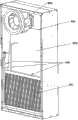
本发明实施例提供了一种热交换器,如图2A、图2B、同时可以一并参阅图3、图4,所示,包括:The embodiment of the present invention provides a heat exchanger, as shown in Fig. 2A and Fig. 2B, which can also be referred to Fig. 3 and Fig. 4, including:
第一风道300和第二风道400,上述第一风道300与第二风道400相互隔离,第一风道300内设置有第一热交换单元301,第二风道设置有第二热交换单元401;其中第一风道300和第二风道400可以由采用隔板200分隔。The
上述第一热交换单元301包括:第一热管热交换器3011和蒸发冷却器3012;上述第二热交换单元401包括:第二热管热交换器4011和冷凝散热器4012;The first
上述第一热管热交换器3011的空腔与第二热管热交换器4011的空腔通过第一管道501连接,使得第一热管热交换器3011的空腔与第二热管热交换器4011的空腔之间形成第一封闭环路;The cavity of the first heat
上述蒸发冷却器3012的空腔与冷凝散热器4012的空腔通过第二管路502连接,使得蒸发冷却器3012的空腔与冷凝散热器4012的空腔之间形成第二封闭环路;The cavity of the
上述第一封闭环路和上述成第二封闭环路中具有能够携带热量的流体;There is a fluid capable of carrying heat in the first closed loop and the second closed loop;
上述热交换器还包括:压缩机5021和第一阀件5024;The heat exchanger above also includes: a
上述压缩机5021设置于流体自蒸发冷却器3012向冷凝散热器4012流动流经的第二管路502中,并且上述压缩机5021的入口通过第二管路502与蒸发冷却器3012连接,压缩机5021的出口通过第二管路502与冷凝散热器4012连接;上述第一阀件5024设置于上述压缩机5021的入口与蒸发冷却器3012之间的第二管路502中;The above-mentioned
在上述第一热管热交换器3011侧的温度高于第一目标温度时开启上述第一阀件5024,并启动压缩机5021使压缩机5021处于工作状态;在上述第一热管热交换器3011侧的温度低于第二目标温度时关闭上述第一阀件5024,并关闭上述压缩机5021使压缩机5021处于停止工作状态;上述第一目标温度和第二目标温度均低于或等于热源正常工作所需的环境温度,且第一目标温度高于或等于上述第二目标温度。When the temperature on the side of the first heat
本实施例采用隔板200分隔两个风道,在各风道使用热交换单元可以对流经风道的风进行强化散热,从而提升热交换效率。另外需要说明的是第一热交换单元301与第二热交换单元401之间的管道500可以有多条,在使用中有的作为回流管路使用,有的作为相变工质或者制冷剂上升管路使用。具体的条数本发明实施例不予限定。以上实施例,在实际控制温度高于目标温度时开启第一阀件使压缩机处于工作状态,实现强化散热;在实际控制温度低于第二目标温度时关闭第一阀件使压缩机处于停止工作状态时,此时热管热交换器仍处于工作状态,也能具有较好散热能力;因而使用本发明实施例方案可以实现分级散热适应不同强度的散热需求,在保证散热能力的前提下关闭压缩机,可以减少压缩机工作时间,不但可以降低能耗实现节能,还可以减少压缩机消耗提升热交换器寿命。In this embodiment, the
本发明实施例可以在机柜使用组合热交换器,集成分体重力的热管热交换器与通信机柜空调系统,实现分级散热,机柜设备低负荷下使用热交换器,高负荷下使用空调。比使用单纯空调器,能耗大幅下降,实现节能。减少空调器使用时间,提高了空调器的使用寿命,提高其整体可靠性。The embodiments of the present invention can use combined heat exchangers in the cabinets, integrating heat pipe heat exchangers with separate gravity and air-conditioning systems in the communication cabinets to realize hierarchical heat dissipation. The heat exchangers are used under low loads of the cabinet equipment, and the air conditioners are used under high loads. Compared with using a simple air conditioner, the energy consumption is greatly reduced and energy saving is realized. Reduce the use time of the air conditioner, improve the service life of the air conditioner, and improve its overall reliability.
可选地,上述第一热管热交换器3011的密封空腔与第二热管热交换器4011的密封空腔之间的封闭环路内填充有相变工质;上述蒸发冷却器3012的密封空腔与冷凝散热器4012的密封空腔之间的封闭环路内填充有制冷剂。Optionally, the closed loop between the sealed cavity of the first heat
进一步地,上述压缩机5021所在的第二管路502还设置有第一旁通管道600;上述第二管路502与第一旁通管道600并行;Further, the
上述第一旁通管道600设置有第二阀件5025,上述第二阀件5025为具有仅允许流体自蒸发冷却器3012向冷凝散热器4012单向流动功能的阀件。The above-mentioned
进一步地,上述压缩机5021的出口与冷凝散热器4012之间的第二管路502中还设置有第四阀件5027;上述第四阀件5027为具有仅允许流体自压缩机5021向冷凝散热器4012单向流动功能的阀件。Further, a
进一步地,上述热交换器还包括:Further, the above heat exchanger also includes:
干燥过滤器5022和截流装置5023;截流装置5023用于限制流经截流装置5023的流体流量,可以采用膨胀阀或者毛细管。上述干燥过滤器5022用于对流经干燥过滤器5022的流体进行干燥处理;The
冷凝散热器4012中流体向蒸发冷却器3012流动的第二管路502安装有干燥过滤器5022,上述干燥过滤器5022与蒸发冷却器3012之间的第二管路502安装有上述截流装置5023。A
进一步地,在上述冷凝散热器4012中流体向蒸发冷却器3012回流的第一管路501一侧设置有第二旁路700;上述冷凝散热器4012中流体向蒸发冷却器3012回流的第一管路501与上述第二旁路700并行;Further, a
上述第二旁路700中设置有第三阀件5026;The
在上述第一阀件5024关闭时,开启上述第三阀件5026;在上述第一阀件5024开启时,关闭上述第三阀件5026。When the
进一步地,上述热交换器,还包括:Further, the above heat exchanger also includes:
上述压缩机5021底部设置有加热带5028;The bottom of the
上述加热带5028在上述热交换器所处的环境温度低于预定值时开启,为上述压缩机5021加热,上述预定值高于或等于第二封闭环路中的流体向压缩机聚集所需的最低温度。The above-mentioned
可选地,上述第一封闭环路内填充有相变工质;上述第二封闭环路内的流体为制冷剂。Optionally, the first closed loop is filled with a phase change working fluid; the fluid in the second closed loop is refrigerant.
可选地,第一热管热交换器3011的入口位于其顶端,出口位于其底端;第二热管热交换器4011的入口位于其底端,出口位于其顶端;Optionally, the inlet of the first heat
蒸发冷却器3012的入口位于其顶端,出口位于其底端;冷凝散热器4012的入口位于其底端,出口位于其顶端。The inlet of the
以下实施例将以上方案的具体实现进行详细说明,本实施例将以通信基站为例进行说明,可以理解的是热交换器的应用不应理解为仅局限于通信基站,因此通信基站不应理解为对本发明实施例的限定。The following embodiments describe the specific implementation of the above scheme in detail. This embodiment will take the communication base station as an example. It can be understood that the application of the heat exchanger should not be understood as being limited to the communication base station, so the communication base station should not understand To limit the embodiments of the present invention.
通信基站机柜用组合散热装置由分体式重力的热管热交换器系统和通信机柜空调器系统,这两个系统是可以独立运行也可以协同运行,在后续实施例中会对此进行说明。两个系统由隔板200分成内循环风道(第一风道300)和外循环风道(第二风道300)。The combined cooling device for the communication base station cabinet consists of a split gravity heat pipe heat exchanger system and a communication cabinet air conditioner system. These two systems can operate independently or in coordination, which will be described in subsequent embodiments. The two systems are divided into an inner circulation air duct (first air duct 300 ) and an outer circulation air duct (second air duct 300 ) by a
在内循环风道(第一风道300)(第一风道300)中有风扇800、第一热交换单元301,空气流经过第一热交换单元301,再由风扇800送入机柜,对通信设备进行冷却;外循环风道(第二风道300)中有风扇900和第二热交换单元401,空气流经过第二热交换单元401,再由风扇900排出,对将通信设备产生的热量带走。There are
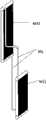
第一热交换单元301可以由一个供分体重力热管热交换器系统使用的第一热管热交换器3011和一个供通信机柜空调器系统使用的蒸发冷却器3012组成,两者可以由边板固定在一起,组成一个整体,两者不连通,相互独立,两者前后位置可互换。需要说明的是固定的方式还可以有很多,本发明实施例不予限定。The first
第二热交换单元401:由一个供分体重力热管热交换器系统使用的第二热管热交换器4011和一个供通信机柜空调器系统使用的冷凝散热器4012组成,两者由共同边板14固定在一起,两者可以由边板固定在一起,组成一个整体,两者不连通,相互独立,两者前后位置可互换。需要说明的是固定的方式还可以有很多,本发明实施例不予限定。The second heat exchange unit 401: consists of a second heat
分体式重力的热管热交换器系统包括:由第一热交换单元301中的第一热管热交换器3011与第二热交换单元401中的第二热管热交换器4011,通过蒸汽上升管和液体下降管相联通,组成了封闭的环路,内部充有制冷剂。The split gravity heat pipe heat exchanger system includes: the first heat
第一热交换单元301中的第一热管热交换器3011位于内循环风道(第一风道300)上,风扇800驱动内部热气流通过第一热管热交换器3011,实现第一热管热交换器3011内相变工质与热空气的热交换;第二热交换单元401中的第二热管热交换器4011位于外循环风道(第二风道400)上,风扇900驱动外部冷气流通过第二热管热交换器4011,实现冷凝散热器4012内相变工质与冷空气的热交换。相变工质在第一热管热交换器3011吸热汽化,经由蒸汽上升管到达第二热管热交换器4011;相变工质在第二热管热交换器4011放热冷凝,经由液体下降管到达第一热管热交换器3011,完成循环。The first heat
通信机柜空调器系统,可以由第一热交换单元301中的蒸发冷却器3012与第二热交换单元401中的冷凝散热器4012,压缩机5021,干燥过滤器5022,截流装置5023(可以是膨胀阀或者毛细管),第二管路502组成封闭的环路,内部充有制冷剂。The communication cabinet air conditioner system can be composed of the
相变工质在第一热交换单元301中的蒸发冷却器3012中吸收被冷却对象(机柜内热空气)热量并气化,形成的低压蒸汽通过第二管路502进入压缩机5021被压缩成高压蒸气,再通过第二管路502进入第二热交换单元401中的冷凝散热器4012被常温冷却空气冷却,凝结成高压液体,经干燥过滤器5022、截流装置5023后变成低压、低温状态进入蒸发冷却器3012,如此周而复始实现连续制冷。The phase-change working medium absorbs the heat of the object to be cooled (hot air in the cabinet) in the
当机柜通信设备发热量大时,通信机柜空调器系统开启,分体式重力的热管热交换器系统关闭,进行制冷;当机柜通信设备发热量不大时,分体式重力的热管热交换器系统开启,通信机柜空调器系统关闭,进行散热。When the heat generated by the communication equipment in the cabinet is large, the air conditioner system of the communication cabinet is turned on, and the split gravity heat pipe heat exchanger system is turned off for cooling; when the heat generated by the communication equipment in the cabinet is not large, the split gravity heat pipe heat exchanger system is turned on , the communication cabinet air conditioner system is turned off for heat dissipation.
第二热交换单元401中心位置要高于第一热交换单元301的中心位置,第一热交换单元单元301与第二热交换单元401可以由一个或多个铜管翅片式换热器或者平行流微通道式换热器组成,蒸汽上升管和液体下降管可以是单根或多根。The center position of the second
热交换器内部的相变工质可以采用氟利昂134A(四氟乙烷,R134A,化学式为:CH2FCF3)。The phase change working medium inside the heat exchanger can be Freon 134A (tetrafluoroethane, R134A, chemical formula: CH2FCF3).
风扇800,风扇900则可以是轴流风扇或离心风扇。本发明实施例对风扇具体使用何种不作限定,以上两种风扇的举例不应理解为对本发明实施例的限定。The
本发明实施例还提供了分体式重力的热管热交换器系统和通信机柜空调器系统独立或者组合工作的工作原理说明。本实施例在上述实施基础上,在通信机柜空调器系统上加入旁通管路,旁通管路上加阀件(可以是单向阀、电磁阀、电动球阀等),控制该旁通管路的开启与关闭,使得系统可以实现在分体重力热管热交换器与通信机柜空调器之间相互转换。The embodiment of the present invention also provides a description of the working principle of the split gravity heat pipe heat exchanger system and the communication cabinet air conditioner system working independently or in combination. In this embodiment, on the basis of the above implementation, a bypass pipeline is added to the communication cabinet air conditioner system, and a valve (which can be a one-way valve, a solenoid valve, an electric ball valve, etc.) is added to the bypass pipeline to control the bypass pipeline. The opening and closing of the system enables the system to realize mutual conversion between the split gravity heat pipe heat exchanger and the communication cabinet air conditioner.
通信机柜空调器系统,在压缩机5021与截流装置5023(可以是膨胀阀或者毛细管)处分别加装旁通第一旁通管道600和第二旁通管道700,在第一旁通管道600上加第二阀件5025,在压缩机5021入口前加第一阀件5024,在压缩机5021出口处加第四阀件5027,在二旁通管道700上加第三阀件5026。具体结构如图3所示。In the communication cabinet air conditioner system, a
当第三阀件5026开启,第一阀件5024关闭时系统为分体式重力的热管热交换器模式。第一阀件5024和第三阀件5026可以采用电磁阀,第二阀件5025和第四阀件5027可以采用单向阀,单向阀是流体只能沿进水口流动,出水口介质却无法回流的装置,用于控制流体单向流动。When the
当第三阀件5026关闭,第一阀件5024开启时系统为通信机柜空调器模式。When the
当机柜通信设备发热量大时,通信机柜空调模式开启,分体重力热管热交换器关闭,进行散热;当机柜通信设备发热量不大时,分体重力热管热交换器开启,通信机柜空调模式关闭,进行散热。When the heat generated by the communication equipment in the cabinet is large, the air conditioner mode of the communication cabinet is turned on, and the split gravity heat pipe heat exchanger is turned off for heat dissipation; when the heat generated by the communication equipment in the cabinet is not large, the split gravity heat pipe heat exchanger is turned on, and the air conditioner mode of the communication cabinet Turn off for cooling.
当空调模式向分体式重力的热管热交换器模式切换完毕时,压缩机5021吸气口的第一阀件5024、压缩机5021排气口的第四阀件5027,可以防止相变工质向压缩机5021中聚集,避免压缩机5021再次启动时形成液击。When the air conditioner mode is switched to the split gravity heat pipe heat exchanger mode, the
压缩机5021底部设置加热带5028,加热带5028可以采用电加热带,在低温情况下加热带5028开启,保持一定温度,防止相变工质向压缩机5021聚积,避免压缩机5021再次启动时形成液击。A
本发明实施例可以在机柜使用组合热交换器,集成分体重力的热管热交换器与通信机柜空调系统,实现分级散热,机柜设备低负荷下使用热交换器,高负荷下使用空调。比使用单纯空调器,能耗大幅下降,实现节能。减少空调器使用时间,提高了空调器的使用寿命,提高其整体可靠性。The embodiments of the present invention can use combined heat exchangers in the cabinets, integrating heat pipe heat exchangers with separate gravity and air-conditioning systems in the communication cabinets to realize hierarchical heat dissipation. The heat exchangers are used under low loads of the cabinet equipment, and the air conditioners are used under high loads. Compared with using a simple air conditioner, the energy consumption is greatly reduced and energy saving is realized. Reduce the use time of the air conditioner, improve the service life of the air conditioner, and improve its overall reliability.
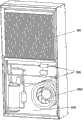
本发明实施例还提供了一种机柜,可以参阅图2A、图2B,包括:机柜内侧和机柜外侧,上述机柜内侧为安装有热源器件的一侧,上述机柜外侧为机柜外部空间;还包括:本发明实施例提供的任意一项的热交换器,且上述热交换器的第一风道300位于机柜内侧,第二风道400位于上述机柜的外侧;上述热交换器的第一热交换单元301位于第二热交换单元401的下方。机柜的原理以及使用方法可以参考以上热交换器实施例。The embodiment of the present invention also provides a cabinet, which can be referred to Fig. 2A and Fig. 2B, including: the inside of the cabinet and the outside of the cabinet, the inside of the cabinet is the side where the heat source device is installed, and the outside of the cabinet is the outer space of the cabinet; it also includes: According to any one of the heat exchangers provided in the embodiments of the present invention, the
本发明实施例可以在机柜使用组合热交换器,集成分体重力的热管热交换器与通信机柜空调系统,实现分级散热,机柜设备低负荷下使用热交换器,高负荷下使用空调。比使用单纯空调器,能耗大幅下降,实现节能。减少空调器使用时间,提高了空调器的使用寿命,提高其整体可靠性。The embodiments of the present invention can use combined heat exchangers in the cabinets, integrating heat pipe heat exchangers with separate gravity and air-conditioning systems in the communication cabinets to realize hierarchical heat dissipation. The heat exchangers are used under low loads of the cabinet equipment, and the air conditioners are used under high loads. Compared with using a simple air conditioner, the energy consumption is greatly reduced and energy saving is realized. Reduce the use time of the air conditioner, improve the service life of the air conditioner, and improve its overall reliability.
值得注意的是,以上仅为本发明较佳的具体实施方式,但本发明的保护范围并不局限于此,任何熟悉本技术领域的技术人员在本发明实施例揭露的技术范围内,可轻易想到的变化或替换,都应涵盖在本发明的保护范围之内。因此,本发明的保护范围应该以权利要求的保护范围为准。It is worth noting that the above are only preferred specific implementation modes of the present invention, but the scope of protection of the present invention is not limited thereto. Any person familiar with the technical field can easily Any changes or substitutions that can be thought of should fall within the protection scope of the present invention. Therefore, the protection scope of the present invention should be determined by the protection scope of the claims.
Claims (10)
Translated fromChinesePriority Applications (3)
| Application Number | Priority Date | Filing Date | Title |
|---|---|---|---|
| CN2012100651569ACN103307658A (en) | 2012-03-13 | 2012-03-13 | Heat exchanger and machine cabinet |
| PCT/CN2012/083670WO2013135048A1 (en) | 2012-03-13 | 2012-10-29 | Heat exchanger and cabinet |
| EP12834576.6AEP2677848B1 (en) | 2012-03-13 | 2012-10-29 | Heat exchanger and cabinet |
Applications Claiming Priority (1)
| Application Number | Priority Date | Filing Date | Title |
|---|---|---|---|
| CN2012100651569ACN103307658A (en) | 2012-03-13 | 2012-03-13 | Heat exchanger and machine cabinet |
Publications (1)
| Publication Number | Publication Date |
|---|---|
| CN103307658Atrue CN103307658A (en) | 2013-09-18 |
Family
ID=49133166
Family Applications (1)
| Application Number | Title | Priority Date | Filing Date |
|---|---|---|---|
| CN2012100651569APendingCN103307658A (en) | 2012-03-13 | 2012-03-13 | Heat exchanger and machine cabinet |
Country Status (3)
| Country | Link |
|---|---|
| EP (1) | EP2677848B1 (en) |
| CN (1) | CN103307658A (en) |
| WO (1) | WO2013135048A1 (en) |
Cited By (11)
| Publication number | Priority date | Publication date | Assignee | Title |
|---|---|---|---|---|
| CN103687445A (en)* | 2013-12-06 | 2014-03-26 | 柳州市豪杰特化工机械有限责任公司 | Electric cabinet water cooling and heat dissipation device |
| WO2014177102A3 (en)* | 2013-12-31 | 2014-12-18 | 中兴通讯股份有限公司 | Thermal control system for closed electronic platform |
| CN104135839B (en)* | 2014-08-13 | 2017-01-04 | 苏州市朗吉科技有限公司 | A kind of machine room-refrigerating plant integrated cabinet system |
| CN107990770A (en)* | 2017-12-28 | 2018-05-04 | 江西鑫田车业有限公司 | A kind of gravity type heat exchanger of 2X2 groups module |
| CN108050873A (en)* | 2017-12-28 | 2018-05-18 | 江西鑫田车业有限公司 | A kind of gravity type heat exchanger |
| CN108088293A (en)* | 2017-12-28 | 2018-05-29 | 江西鑫田车业有限公司 | A kind of gravity type heat exchanger of 1X1 groups module |
| CN105928235B (en)* | 2016-04-28 | 2018-08-31 | 香江科技股份有限公司 | Double-condenser data center cooling system with phase change cold-storage and its control method |
| CN108562181A (en)* | 2017-12-28 | 2018-09-21 | 江西鑫田车业有限公司 | A kind of gravity type heat exchanger |
| CN109398130A (en)* | 2018-10-31 | 2019-03-01 | 山东鲁能智能技术有限公司 | A kind of charger and method based on the heat exchange of fresh air heat-exchange device |
| CN109963447A (en)* | 2019-04-25 | 2019-07-02 | 魏新文 | A kind of electric power electric cabinet of dust-proof radiating |
| CN116801569A (en)* | 2022-03-16 | 2023-09-22 | 广运机械工程股份有限公司 | Heat exchange system |
Families Citing this family (7)
| Publication number | Priority date | Publication date | Assignee | Title |
|---|---|---|---|---|
| CN105246278A (en)* | 2015-10-30 | 2016-01-13 | 南京华脉科技股份有限公司 | Liftable underground integrated cabinet |
| EP3352432A1 (en) | 2017-01-20 | 2018-07-25 | Sentiance NV | Method and system for classifying an activity of a user |
| CN107466192A (en)* | 2017-08-24 | 2017-12-12 | 智车优行科技(上海)有限公司 | Cooling system and electric automobile |
| CN107896470A (en)* | 2017-11-22 | 2018-04-10 | 阳泉新科联合电子科技有限公司 | A kind of server sealed thermostat case |
| CN112492858A (en)* | 2020-12-09 | 2021-03-12 | 北京东土正创科技有限公司 | System and method for adjusting internal temperature of sealed outdoor cabinet |
| CN114423209B (en)* | 2022-01-13 | 2024-02-13 | 日照钢铁控股集团有限公司 | Electronic information automatic control cabinet |
| CN115666073A (en)* | 2022-10-13 | 2023-01-31 | 珠海格力电器股份有限公司 | Cooling control method and device and cooling system |
Citations (5)
| Publication number | Priority date | Publication date | Assignee | Title |
|---|---|---|---|---|
| CN101233374A (en)* | 2005-07-29 | 2008-07-30 | 大金工业株式会社 | freezer |
| WO2008128311A2 (en)* | 2007-04-23 | 2008-10-30 | Francisquini Melquisedec | Improvement in air-conditioner for cabinets |
| CN101737906A (en)* | 2009-11-08 | 2010-06-16 | 海信科龙电器股份有限公司 | Standby electric heating control device and method of air conditioner |
| CN201897275U (en)* | 2010-12-02 | 2011-07-13 | 苏州昆拓热控系统股份有限公司 | Energy-saving cabinet air conditioner |
| CN102297487A (en)* | 2011-07-22 | 2011-12-28 | 深圳市英维克科技有限公司 | Air conditioner and heat tube integrated machine |
Family Cites Families (7)
| Publication number | Priority date | Publication date | Assignee | Title |
|---|---|---|---|---|
| CN2369006Y (en)* | 1999-02-24 | 2000-03-15 | 青岛市家用电器研究所 | Heating belt for compressor |
| JP2007234791A (en)* | 2006-02-28 | 2007-09-13 | Fuji Electric Retail Systems Co Ltd | Electronic apparatus cooling device |
| CN100516674C (en)* | 2006-12-08 | 2009-07-22 | 苏州昆拓冷机有限公司 | Energy-saving air conditioner |
| WO2010145434A1 (en)* | 2009-06-15 | 2010-12-23 | 华为技术有限公司 | Heat exchanger, heat dissipation method of same and communication apparatus |
| CN201733563U (en)* | 2010-08-06 | 2011-02-02 | 苏州市朗吉科技有限公司 | Air-conditioner system suitable for cabinets |
| CN201750670U (en)* | 2010-09-08 | 2011-02-16 | 苏州昆拓冷机有限公司 | Cabinet air-conditioner |
| CN102486324A (en)* | 2010-12-02 | 2012-06-06 | 苏州昆拓热控系统股份有限公司 | Energy-saving cabinet type air-conditioner |
- 2012
- 2012-03-13CNCN2012100651569Apatent/CN103307658A/enactivePending
- 2012-10-29EPEP12834576.6Apatent/EP2677848B1/ennot_activeNot-in-force
- 2012-10-29WOPCT/CN2012/083670patent/WO2013135048A1/enactiveApplication Filing
Patent Citations (5)
| Publication number | Priority date | Publication date | Assignee | Title |
|---|---|---|---|---|
| CN101233374A (en)* | 2005-07-29 | 2008-07-30 | 大金工业株式会社 | freezer |
| WO2008128311A2 (en)* | 2007-04-23 | 2008-10-30 | Francisquini Melquisedec | Improvement in air-conditioner for cabinets |
| CN101737906A (en)* | 2009-11-08 | 2010-06-16 | 海信科龙电器股份有限公司 | Standby electric heating control device and method of air conditioner |
| CN201897275U (en)* | 2010-12-02 | 2011-07-13 | 苏州昆拓热控系统股份有限公司 | Energy-saving cabinet air conditioner |
| CN102297487A (en)* | 2011-07-22 | 2011-12-28 | 深圳市英维克科技有限公司 | Air conditioner and heat tube integrated machine |
Non-Patent Citations (1)
| Title |
|---|
| 孙丽颖,马最良: "冷剂自然循环空调机的特性与应用", 《哈尔滨商业大学学报(自然科学版)》* |
Cited By (12)
| Publication number | Priority date | Publication date | Assignee | Title |
|---|---|---|---|---|
| CN103687445A (en)* | 2013-12-06 | 2014-03-26 | 柳州市豪杰特化工机械有限责任公司 | Electric cabinet water cooling and heat dissipation device |
| WO2014177102A3 (en)* | 2013-12-31 | 2014-12-18 | 中兴通讯股份有限公司 | Thermal control system for closed electronic platform |
| CN104754917A (en)* | 2013-12-31 | 2015-07-01 | 中兴通讯股份有限公司 | Heat control system of closed electronic platform |
| CN104135839B (en)* | 2014-08-13 | 2017-01-04 | 苏州市朗吉科技有限公司 | A kind of machine room-refrigerating plant integrated cabinet system |
| CN105928235B (en)* | 2016-04-28 | 2018-08-31 | 香江科技股份有限公司 | Double-condenser data center cooling system with phase change cold-storage and its control method |
| CN107990770A (en)* | 2017-12-28 | 2018-05-04 | 江西鑫田车业有限公司 | A kind of gravity type heat exchanger of 2X2 groups module |
| CN108050873A (en)* | 2017-12-28 | 2018-05-18 | 江西鑫田车业有限公司 | A kind of gravity type heat exchanger |
| CN108088293A (en)* | 2017-12-28 | 2018-05-29 | 江西鑫田车业有限公司 | A kind of gravity type heat exchanger of 1X1 groups module |
| CN108562181A (en)* | 2017-12-28 | 2018-09-21 | 江西鑫田车业有限公司 | A kind of gravity type heat exchanger |
| CN109398130A (en)* | 2018-10-31 | 2019-03-01 | 山东鲁能智能技术有限公司 | A kind of charger and method based on the heat exchange of fresh air heat-exchange device |
| CN109963447A (en)* | 2019-04-25 | 2019-07-02 | 魏新文 | A kind of electric power electric cabinet of dust-proof radiating |
| CN116801569A (en)* | 2022-03-16 | 2023-09-22 | 广运机械工程股份有限公司 | Heat exchange system |
Also Published As
| Publication number | Publication date |
|---|---|
| EP2677848A1 (en) | 2013-12-25 |
| WO2013135048A1 (en) | 2013-09-19 |
| EP2677848B1 (en) | 2017-01-04 |
| EP2677848A4 (en) | 2015-04-01 |
Similar Documents
| Publication | Publication Date | Title |
|---|---|---|
| CN103307658A (en) | Heat exchanger and machine cabinet | |
| CN102607120B (en) | Liquid pump driving heat pipe device for cascade mechanical refrigerating and operation method | |
| CN105180490B (en) | Integrated natural cooling machine room air conditioning system | |
| US20180042140A1 (en) | Server rack heat sink system with combination of liquid cooling device and auxiliary heat sink device | |
| CN203848433U (en) | Heat pipe and heat pump dual-mode air conditioner with evaporative condenser | |
| CN108759138B (en) | Operation method and system of secondary throttling middle incomplete cooling refrigerating system | |
| CN203605514U (en) | Air-cooling compression condensing unit of microchannel heat exchanger | |
| CN106332514A (en) | Heat Pipe Cooling System for High Heat Density Cabinets | |
| CN106288515A (en) | A kind of System and method for for the waste heat recovery to data center | |
| CN108488918A (en) | A kind of full effect multi-mode energy-saving air conditioning system | |
| CN106766294A (en) | Heat pipe VRF Air Conditioning System | |
| CN104236177B (en) | A kind of phase-transition heat-storage, coolant are crossed cold-heat-exchanging exchange system and are adopted its air conditioning system | |
| CN114322345B (en) | Heat dissipation system, heat management equipment and working method of heat dissipation system | |
| JP7603229B2 (en) | Air Conditioning Equipment | |
| CN210892235U (en) | Natural cooling multi-connected refrigerating system with built-in gravity heat pipe | |
| CN106585318B (en) | Battery cooling system of electric vehicle | |
| CN106322590A (en) | Heat pipe cooling system for machine room | |
| CN208170604U (en) | Air-conditioning system and air conditioner | |
| CN207762059U (en) | Hydraulic press hydraulic oil cooling device | |
| CN105509200A (en) | Independent fresh air dehumidifying device capable of enhancing heat dissipation | |
| CN206155082U (en) | Battery Cooling System for Electric Vehicles | |
| CN205316562U (en) | But enhancing heat emission's new trend device that independently dehumidifies | |
| CN108716793A (en) | A kind of oil separation device and its heat pump system | |
| CN103925737A (en) | Air conditioner system with evaporation type condenser | |
| CN204176833U (en) | A kind of energy-saving air central utilizing natural cooling source |
Legal Events
| Date | Code | Title | Description |
|---|---|---|---|
| C06 | Publication | ||
| PB01 | Publication | ||
| C10 | Entry into substantive examination | ||
| SE01 | Entry into force of request for substantive examination | ||
| RJ01 | Rejection of invention patent application after publication | ||
| RJ01 | Rejection of invention patent application after publication | Application publication date:20130918 |