CN103307069A - Multi-section telescopic device - Google Patents
Multi-section telescopic deviceDownload PDFInfo
- Publication number
- CN103307069A CN103307069ACN2012100648617ACN201210064861ACN103307069ACN 103307069 ACN103307069 ACN 103307069ACN 2012100648617 ACN2012100648617 ACN 2012100648617ACN 201210064861 ACN201210064861 ACN 201210064861ACN 103307069 ACN103307069 ACN 103307069A
- Authority
- CN
- China
- Prior art keywords
- section
- telescopic
- side wall
- telescopic section
- linear
- Prior art date
- Legal status (The legal status is an assumption and is not a legal conclusion. Google has not performed a legal analysis and makes no representation as to the accuracy of the status listed.)
- Pending
Links
Images


Classifications
- E—FIXED CONSTRUCTIONS
- E04—BUILDING
- E04B—GENERAL BUILDING CONSTRUCTIONS; WALLS, e.g. PARTITIONS; ROOFS; FLOORS; CEILINGS; INSULATION OR OTHER PROTECTION OF BUILDINGS
- E04B1/00—Constructions in general; Structures which are not restricted either to walls, e.g. partitions, or floors or ceilings or roofs
- E04B1/343—Structures characterised by movable, separable, or collapsible parts, e.g. for transport
- E04B1/34305—Structures characterised by movable, separable, or collapsible parts, e.g. for transport telescopic
- F—MECHANICAL ENGINEERING; LIGHTING; HEATING; WEAPONS; BLASTING
- F16—ENGINEERING ELEMENTS AND UNITS; GENERAL MEASURES FOR PRODUCING AND MAINTAINING EFFECTIVE FUNCTIONING OF MACHINES OR INSTALLATIONS; THERMAL INSULATION IN GENERAL
- F16M—FRAMES, CASINGS OR BEDS OF ENGINES, MACHINES OR APPARATUS, NOT SPECIFIC TO ENGINES, MACHINES OR APPARATUS PROVIDED FOR ELSEWHERE; STANDS; SUPPORTS
- F16M11/00—Stands or trestles as supports for apparatus or articles placed thereon ; Stands for scientific apparatus such as gravitational force meters
- F16M11/20—Undercarriages with or without wheels
- F16M11/24—Undercarriages with or without wheels changeable in height or length of legs, also for transport only, e.g. by means of tubes screwed into each other
- F16M11/26—Undercarriages with or without wheels changeable in height or length of legs, also for transport only, e.g. by means of tubes screwed into each other by telescoping, with or without folding
- F16M11/28—Undercarriages for supports with one single telescoping pillar
- H—ELECTRICITY
- H01—ELECTRIC ELEMENTS
- H01Q—ANTENNAS, i.e. RADIO AERIALS
- H01Q1/00—Details of, or arrangements associated with, antennas
- H01Q1/08—Means for collapsing antennas or parts thereof
- H01Q1/10—Telescopic elements
- H—ELECTRICITY
- H01—ELECTRIC ELEMENTS
- H01Q—ANTENNAS, i.e. RADIO AERIALS
- H01Q1/00—Details of, or arrangements associated with, antennas
- H01Q1/12—Supports; Mounting means
- H01Q1/1235—Collapsible supports; Means for erecting a rigid antenna
- E—FIXED CONSTRUCTIONS
- E04—BUILDING
- E04H—BUILDINGS OR LIKE STRUCTURES FOR PARTICULAR PURPOSES; SWIMMING OR SPLASH BATHS OR POOLS; MASTS; FENCING; TENTS OR CANOPIES, IN GENERAL
- E04H12/00—Towers; Masts or poles; Chimney stacks; Water-towers; Methods of erecting such structures
- E04H12/18—Towers; Masts or poles; Chimney stacks; Water-towers; Methods of erecting such structures movable or with movable sections, e.g. rotatable or telescopic
- E04H12/182—Towers; Masts or poles; Chimney stacks; Water-towers; Methods of erecting such structures movable or with movable sections, e.g. rotatable or telescopic telescopic
- F—MECHANICAL ENGINEERING; LIGHTING; HEATING; WEAPONS; BLASTING
- F16—ENGINEERING ELEMENTS AND UNITS; GENERAL MEASURES FOR PRODUCING AND MAINTAINING EFFECTIVE FUNCTIONING OF MACHINES OR INSTALLATIONS; THERMAL INSULATION IN GENERAL
- F16B—DEVICES FOR FASTENING OR SECURING CONSTRUCTIONAL ELEMENTS OR MACHINE PARTS TOGETHER, e.g. NAILS, BOLTS, CIRCLIPS, CLAMPS, CLIPS OR WEDGES; JOINTS OR JOINTING
- F16B7/00—Connections of rods or tubes, e.g. of non-circular section, mutually, including resilient connections
- F16B7/10—Telescoping systems
- F16B7/105—Telescoping systems locking in discrete positions, e.g. in extreme extended position
Landscapes
- Engineering & Computer Science (AREA)
- General Engineering & Computer Science (AREA)
- Architecture (AREA)
- Mechanical Engineering (AREA)
- Physics & Mathematics (AREA)
- Electromagnetism (AREA)
- Civil Engineering (AREA)
- Structural Engineering (AREA)
- Manipulator (AREA)
- Lining And Supports For Tunnels (AREA)
- Endoscopes (AREA)
Abstract
Description
Translated fromChinese技术领域technical field
本发明涉及一种多节可伸缩装置。The invention relates to a multi-section telescopic device.
背景技术Background technique
在天文观测、电子通信、医疗和起重等许多工程器械领域中,都会使用到多节可伸缩装置,例如在悬吊式X光摄影系统中,使用多节可伸缩装置来控制X光摄像头的位置。但是,现有的多节伸缩装置存在精密度不高、不易控制等缺陷。In many fields of engineering equipment such as astronomical observation, electronic communication, medical treatment and lifting, multi-section telescopic devices are used. For example, in a suspended X-ray photography system, multi-section telescopic devices are used to control the X-ray Location. However, the existing multi-section expansion device has defects such as low precision and difficult control.
发明内容Contents of the invention
鉴于以上内容,有必要提供一种精密度高、易控制的多节可伸缩装置。In view of the above, it is necessary to provide a multi-section retractable device with high precision and easy control.
一种多节可伸缩装置,包括一中空的第一伸缩节和一套接于所述第一伸缩节的内腔中的第二伸缩节,所述第一伸缩节的一第一侧壁的内侧面上设有一直线滑轨,所述第一伸缩节的一第二侧壁和一第三侧壁的内侧面上分别设有一直线滑道,所述第二伸缩节的一第四侧壁的外侧面上设有一可在所述直线滑轨上滑动的直线滑槽,所述第二伸缩节的一第五侧壁和一第六侧壁的外侧面上分别设有一可在所述直线滑道内滑动的凸轮随动器。A multi-section telescopic device, comprising a hollow first telescopic section and a second telescopic section sleeved in the inner cavity of the first telescopic section, a first side wall of the first telescopic section A linear slide rail is provided on the inner surface, a linear slideway is respectively provided on the inner surface of a second side wall and a third side wall of the first expansion joint, and a fourth side wall of the second expansion joint A linear chute that can slide on the linear slide rail is provided on the outer surface of the second expansion joint, and a fifth side wall and a sixth side wall of the second telescopic joint are respectively provided with a linear slot that can slide on the linear guide rail. A cam follower that slides in a slideway.
优选地,所述第一伸缩节的上下开口位置上各设有一阻挡所述第二伸缩节的上端滑出所述第一伸缩节的内腔范围的阻挡结构。Preferably, the upper and lower openings of the first expansion joint are each provided with a blocking structure that prevents the upper end of the second expansion joint from sliding out of the inner cavity of the first expansion joint.
优选地,所述第一伸缩节的上开口位置上设有一阻挡片,所述阻挡片的一端固定在所述伸缩节的一上底边上,一端沿平行于所述伸缩节的上底面且靠向所述上底面的中心的方向延伸。Preferably, a blocking sheet is provided at the upper opening of the first telescopic section, one end of the blocking sheet is fixed on an upper bottom edge of the telescopic section, and one end is parallel to the upper bottom surface of the telescopic section and Extending toward the center of the upper bottom surface.
优选地,所述第一伸缩节的下开口位置上设有一阻挡件,所述阻挡件包括一固定在所述伸缩节的一下底边上的固定部及一凸设于所述固定部上的缓冲弹性部。Preferably, a stopper is provided at the lower opening of the first expansion joint, and the stopper includes a fixing part fixed on the lower bottom edge of the expansion joint and a protrusion protruding from the fixing part. Cushion elastic part.
优选地,所述第一伸缩节与所述第二伸缩节为相似的中空直棱柱体。Preferably, the first expansion joint and the second expansion joint are similar hollow right prisms.
优选地,所述第一伸缩节与所述第二伸缩节均包括若干侧壁及将所述若干侧壁连接形成中空直棱柱体的若干连接筋片。Preferably, both the first telescopic section and the second telescopic section include several side walls and several connecting ribs connecting the several side walls to form a hollow right prism.
优选地,所述若干连接筋片中的每一连接筋片连接所述若干侧板中的三个侧板。Preferably, each connecting rib in the plurality of connecting ribs connects three side panels in the plurality of side panels.
优选地,所述第一伸缩节与所述第二伸缩节均为中空的正六棱柱体。Preferably, both the first expansion joint and the second expansion joint are hollow regular hexagonal prisms.
优选地,所述第一侧壁、第二侧壁和第三侧壁均为互不相接,所述第四侧壁、第五侧壁和第六侧壁均为互不相接。Preferably, the first side wall, the second side wall and the third side wall are not connected to each other, and the fourth side wall, the fifth side wall and the sixth side wall are not connected to each other.
优选地,所述第一伸缩节的所述第一侧壁的内侧面上设有两个相互平行且间隔一定距离的所述直线滑轨,所述第二伸缩节的所述第四侧壁的外侧面上设有两个可分别在所述两个直线滑轨上滑动的所述直线滑槽。Preferably, the inner side of the first side wall of the first expansion joint is provided with two linear slide rails parallel to each other and spaced apart from each other, and the fourth side wall of the second expansion joint Two linear slide grooves that can slide on the two linear slide rails are provided on the outer surface of the two linear guide rails.
与现有技术相比,在上述的多节可伸缩装置中,以直线滑轨导向为主、两条直线滑道导向为辅的导向机构确保了各伸缩节间的运动精密度,并藉由凸轮随动器与直线滑道的配合确保了各伸缩节间的运动顺滑度。Compared with the prior art, in the above-mentioned multi-section telescopic device, the guiding mechanism mainly guided by linear slide rails and supplemented by two linear slide rails ensures the movement precision between each telescopic section, and by The cooperation of the cam follower and the linear slideway ensures the smoothness of movement between the telescopic joints.
附图说明Description of drawings
图1是本发明一较佳实施例中的多节可伸缩装置的立体分解图。Fig. 1 is an exploded perspective view of a multi-section telescopic device in a preferred embodiment of the present invention.
图2是图1所示的多节可伸缩装置中的一伸缩节的立体图。Fig. 2 is a perspective view of a telescopic section in the multi-section telescopic device shown in Fig. 1 .
图3是图1所示的多节可伸缩装置中的另一伸缩节的立体图。Fig. 3 is a perspective view of another telescopic section in the multi-section telescopic device shown in Fig. 1 .
图4是图3所示的伸缩节的另一视角的立体图。Fig. 4 is a perspective view of another viewing angle of the expansion joint shown in Fig. 3 .
图5是图1所示的多节可伸缩装置的立体组装图。Fig. 5 is a three-dimensional assembly view of the multi-section telescopic device shown in Fig. 1 .
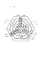
图6是图5所示的多节可伸缩装置的俯视图。Fig. 6 is a top view of the multi-section telescopic device shown in Fig. 5 .
主要元件符号说明Description of main component symbols
如下具体实施方式将结合上述附图进一步说明本发明。The following specific embodiments will further illustrate the present invention in conjunction with the above-mentioned drawings.
具体实施方式Detailed ways
请参阅图1,在一较佳实施方式中,一种多节可伸缩装置1包括五个伸缩节10-50。所述伸缩节10-50可首尾相接地嵌套在一起,形成一个可伸缩的装置,本领域的技术人员应当理解,伸缩节的个数可以根据应用的需要增加或减少,由于这些伸缩节具有相似的结构,为更加清楚和简洁的阐述本实施方式,下文仅着重对伸缩节10与伸缩节20加以说明。Please refer to FIG. 1 , in a preferred embodiment, a multi-section
所述伸缩节10可为一上下中空的直棱柱体,请参阅图2,在图2所示的实施方式中,所述伸缩节10为一上下中空的正六棱柱体,所述伸缩节10包括六个与上下底面垂直的侧壁11-16及将所述侧壁11-16连接形成一正六棱柱体的若干连接筋片17,每一连接筋片17连接侧壁11-16其中的三个。这样的实施方式,藉由多个连接筋片17将可分离制造的侧壁11-16连接成型,相对于传统的一体成型的伸缩节制造方式,可以在不开设模具的条件下生产制造,降低了制造难度,减少了制造成本。The
所述伸缩节10的上下开口位置上各设有一个阻挡结构,用于阻挡所述伸缩节20的上端滑出所述伸缩节10的内腔范围。如图2所示,所述伸缩节10的上开口位置上设有一上阻挡件18,用于阻挡所述伸缩节20的上端滑出所述伸缩节10的上开口。所述上阻挡件18可为一矩形金属片,其一端固定在所述伸缩节10的一上底边上,一端沿平行于所述伸缩节10的上底面且靠向所述上底面的中心的方向延伸。所述伸缩节10的下开口位置上设有至少一下阻挡件19,所述下阻挡件19包括一固定在所述伸缩节10的一下底边上的固定部191及一凸设于所述固定部191上的缓冲弹性部192,所述缓冲弹性部192例如可以为一弹性塑胶件,用于在所述伸缩节20在所述伸缩节10的内腔向下滑动时阻挡所述伸缩节20的上端滑出所述伸缩节10的下开口,且可以在所述伸缩节20抵靠在所述下阻挡件19上时起缓冲作用。The upper and lower openings of the
所述侧壁11的内侧面上设有至少一直线滑轨111,在图2所示的实施方式中,考虑到悬吊式应用中所述伸缩节10在各伸缩节中的受力最大,所述侧壁11的内侧面上设有两个相互平行且间隔一定距离的直线滑轨111,这样,即使在下端的伸缩节有较大的承重负担的情况下,也可以确保所述直线滑轨111产生的导向力的均衡和稳定。本领域的技术人员应当理解,所述直线滑轨111的数量可以根据承重负担和精确度的需要增加或减少。At least one
与所述侧壁11不相接且相互也不相接的两侧壁13和15的内侧面上分别设有两条直线导轨131和151,两条直线导轨131在所述侧壁13的内侧面上形成一直线滑道132,两条直线导轨151在所述侧壁15的内侧面上形成一直线滑道152。这样,在所述侧壁11的内侧面上的直线滑轨111、所述侧壁13和15的内侧面上的两条直线滑道131和151就形成了一个呈三角形顶点的稳固导向结构,可以确保所述伸缩节20在所述伸缩节10的内腔运动时具有较高的精确性,且不易发生偏心运动。Two
所述伸缩节20具有与所述伸缩节10相似的结构,请参阅图3和图4,在图3和图4所示的实施方式中,所述伸缩节20也为一上下中空的正六棱柱体,所述伸缩节20包括六个与上下底面垂直的侧壁21-26及将所述侧壁21-26连接形成一正六棱柱体的若干连接筋片27,每一连接筋片27连接侧壁21-26其中的三个。所述侧壁21的内侧面上设有一直线滑轨211,所述侧壁23的内侧面上设有两条直线导轨231,该两条直线导轨231形成一直线滑道232,所述侧壁25的内侧面上设有两条直线导轨251,该两条直线导轨251形成一直线滑道252。所述伸缩节20上也设有与所述伸缩节10相似的用于阻挡伸缩节30的上端滑出所述伸缩节20内腔范围的阻挡结构,例如,所述伸缩节20的上开口位置上设有一上阻挡件28,下开口位置上设有一下阻挡件29。所述上阻挡件28可为一矩形金属片,其一端固定在所述伸缩节20的一上底边上,一端沿平行于所述伸缩节20的上底面且靠向所述上底面的中心的方向延伸。所述下阻挡件29包括一固定在所述伸缩节20的一下底边上的固定部291及一凸设于所述固定部291上的缓冲弹性部292,所述缓冲弹性部292例如可以为一弹性塑胶件。The
所述伸缩节20与所述伸缩节10不同的结构在于,所述伸缩节20的侧壁21、23和25的外侧面上还设有与所述伸缩节10内腔中的导向结构相配合的滑动结构。所述侧壁21的外侧面上设有两条直线滑槽212,其分别可在所述伸缩节10的两条直线滑轨111上做直线滑动。所述侧壁23的外侧面上设有一凸轮随动器233,所述凸轮随动器233可包括若干导轮234,在图3和图4所示的实施方式中,所述凸轮随动器233包括四个导轮234。所述凸轮随动器233可在所述伸缩节10内腔中的直线滑道131中做直线滑动。所述侧壁25的外侧面设有与所述凸轮随动器233相同的凸轮随动器253,所述凸轮随动器253包括四个导轮254。所述凸轮随动器253可在所述伸缩节10内腔中的直线滑道151中做直线滑动。由于所述凸轮随动器233和253在所述直线滑道131和151中滑动时可减小摩擦阻力,使得所述伸缩节20与所述伸缩节10之间的相对运动更加的顺滑。The structure of the
请继续参阅图5和图6,组装所述多节可伸缩装置1时,将所述伸缩装置20的上端置入所述伸缩装置10的内腔,所述伸缩节20外壁上的两直线滑槽212分别啮合在所述伸缩节10内壁上的两直线滑轨111上,所述伸缩节20外壁上的两凸轮随动器233和253分别嵌入所述伸缩节10内壁上的两直线滑道132和152中,此时,所述伸缩节20的两直线滑槽212可分别在所述伸缩节10的两直线滑轨111上做直线滑动,所述伸缩节20的两凸轮随动器233和253可分别在所述伸缩节10的两直线滑道132和152中做直线滑动,同时由于所述伸缩节10的上下开口位置上的上阻挡件18和下阻挡件19,所述伸缩节20的上端不会滑出所述伸缩节10的内腔范围。Please continue to refer to Figure 5 and Figure 6, when assembling the multi-section
由于伸缩节30-50的结构与伸缩节10和20的结构相似,因此,可以按照与伸缩节10和20相似的组装方法,将伸缩节10-50组装成一个整体的多节伸缩装置1。Since the structures of the expansion joints 30-50 are similar to those of the
至此,本实施方式已结合附图作详尽说明,本实施方式中的多节可伸缩装置,以所述直线滑轨导向为主、两条直线滑道导向为辅的导向机构确保了各伸缩节间的运动精密度,并藉由凸轮随动器与直线滑道配合的确保了各伸缩节间的运动顺滑度。另外,藉由多个连接筋片将可分离制造的侧壁连接成型,相对于传统的一体成型的伸缩节制造方式,可以在不开设模具的条件下生产制造,降低了制造难度,减少了制造成本。So far, this embodiment has been described in detail in conjunction with the accompanying drawings. The multi-section telescopic device in this embodiment uses the linear slide rail as the main guide and the two linear slide guides as the auxiliary guide mechanism to ensure that each telescopic joint The precision of the movement between them, and the smoothness of the movement between the expansion joints is ensured by the cooperation of the cam follower and the linear slideway. In addition, the side walls that can be manufactured separately are connected and formed by multiple connecting ribs. Compared with the traditional integrally formed expansion joint manufacturing method, it can be manufactured without opening a mold, which reduces the difficulty of manufacturing and reduces the cost of manufacturing. cost.
Claims (10)
Translated fromChinesePriority Applications (3)
| Application Number | Priority Date | Filing Date | Title |
|---|---|---|---|
| CN2012100648617ACN103307069A (en) | 2012-03-13 | 2012-03-13 | Multi-section telescopic device |
| TW101108773ATW201337140A (en) | 2012-03-13 | 2012-03-15 | Multi-member telescopic mechanism |
| US13/685,628US8549812B1 (en) | 2012-03-13 | 2012-11-26 | Multi-section telescoping structure |
Applications Claiming Priority (1)
| Application Number | Priority Date | Filing Date | Title |
|---|---|---|---|
| CN2012100648617ACN103307069A (en) | 2012-03-13 | 2012-03-13 | Multi-section telescopic device |
Publications (1)
| Publication Number | Publication Date |
|---|---|
| CN103307069Atrue CN103307069A (en) | 2013-09-18 |
Family
ID=49132651
Family Applications (1)
| Application Number | Title | Priority Date | Filing Date |
|---|---|---|---|
| CN2012100648617APendingCN103307069A (en) | 2012-03-13 | 2012-03-13 | Multi-section telescopic device |
Country Status (3)
| Country | Link |
|---|---|
| US (1) | US8549812B1 (en) |
| CN (1) | CN103307069A (en) |
| TW (1) | TW201337140A (en) |
Cited By (7)
| Publication number | Priority date | Publication date | Assignee | Title |
|---|---|---|---|---|
| CN105972316A (en)* | 2016-06-01 | 2016-09-28 | 江苏大浪电气制造有限公司 | Extensible pore type bridge |
| CN107359568A (en)* | 2017-08-30 | 2017-11-17 | 江苏叙然信息科技有限公司 | A kind of cable testing bridge |
| CN107425479A (en)* | 2017-06-07 | 2017-12-01 | 江苏万奇电器集团有限公司 | A kind of two-way telescopic cable line sink bridge frame |
| CN108799277A (en)* | 2017-04-28 | 2018-11-13 | 斯凯孚公司 | Telescopic mast |
| CN113184162A (en)* | 2021-05-10 | 2021-07-30 | 上海晋飞碳纤科技股份有限公司 | Small composite material sliding structure and manufacturing method |
| CN115748978A (en)* | 2022-11-15 | 2023-03-07 | 山东建筑大学 | Self-adaptive building skin all-direction different-length telescopic sliding device |
| CN117328341A (en)* | 2023-09-20 | 2024-01-02 | 石家庄铁道大学 | A kind of emergency bridge pier based on retractable pier body |
Families Citing this family (24)
| Publication number | Priority date | Publication date | Assignee | Title |
|---|---|---|---|---|
| DK177708B1 (en)* | 2012-09-06 | 2014-03-24 | Falck Schmidt Defence Systems As | A telescopic mast |
| DE102013206348A1 (en)* | 2013-04-11 | 2014-10-16 | Aktiebolaget Skf | Lifting column |
| CH709471A2 (en)* | 2014-04-04 | 2015-10-15 | Villiger Public Systems Gmbh | Lifting device on a truck vehicle. |
| US9371663B2 (en)* | 2014-05-07 | 2016-06-21 | Us Tower Corporation | Internally keyed extruded mast system |
| US10550596B2 (en)* | 2014-07-01 | 2020-02-04 | Micoperi Energia S.R.L. | Support tower, particularly for a wind turbine |
| FR3024720B1 (en)* | 2014-08-07 | 2018-11-16 | Manitou Bf | TELESCOPIC HANDLING DEVICE HAVING AT LEAST TWO RELATIVE SLIDING ELEMENTS |
| US10113573B2 (en)* | 2015-11-05 | 2018-10-30 | Raytheon Company | Sequencing locking mechanism for telescoging structures |
| US9739048B2 (en)* | 2015-11-18 | 2017-08-22 | Jorge Cueto | Telescopic structural systems and construction method |
| NZ742498A (en)* | 2015-12-18 | 2023-05-26 | Ind Galvanizers Corp Pty Ltd | A support |
| US9670948B1 (en) | 2016-01-27 | 2017-06-06 | The Will-Burt Company | Latch for sequentially extended mechanical mast |
| US10881385B2 (en)* | 2016-09-13 | 2021-01-05 | Intuitive Surgical Operations, Inc. | Radial telescoping guide apparatus for delivery of a flexible instrument and methods of use |
| DK179825B1 (en)* | 2017-12-15 | 2019-07-15 | Falck-Schmidt Jan | Telescopic Mast |
| US10746349B2 (en)* | 2018-01-15 | 2020-08-18 | Hamaye Co | Extendable cage telescopic system |
| US10131452B1 (en)* | 2018-03-23 | 2018-11-20 | Northrop Grumman Systems Corporation | Integrated telescopic boom and large deployable reflector |
| DK179982B1 (en) | 2018-05-01 | 2019-12-03 | Falck-Schmidt Jan | Telescopic Mast |
| CN112805140B (en)* | 2018-09-28 | 2022-09-23 | 通用电气公司 | Method for manufacturing a telescoping wind turbine tower structure |
| US10563402B1 (en)* | 2018-12-27 | 2020-02-18 | King Saud University | Method of connecting a circular concrete-filled steel tubular column to a reinforced concrete footing |
| US11052569B2 (en)* | 2019-05-30 | 2021-07-06 | Jorge Cueto | Mold system for a modular telescoping barrier and method of construction |
| US10816133B1 (en)* | 2019-05-31 | 2020-10-27 | Advanced Mounting and Design, Inc. | Telescoping structural support device |
| US11724920B2 (en)* | 2019-07-15 | 2023-08-15 | Roccor, Llc | Telescoping boom systems, devices, and methods |
| US11346122B2 (en)* | 2019-10-15 | 2022-05-31 | M J Engineering LLC | Layered multi-body support structure |
| US12270430B2 (en)* | 2019-10-15 | 2025-04-08 | MJ Engineering LLC | Layered multi-body support structure |
| US11796172B2 (en)* | 2020-01-30 | 2023-10-24 | All American Services, LLC | Portable flaring apparatus |
| WO2023230497A1 (en)* | 2022-05-26 | 2023-11-30 | MJ Engineering LLC | Layered multi-body support structure |
Citations (8)
| Publication number | Priority date | Publication date | Assignee | Title |
|---|---|---|---|---|
| US3495370A (en)* | 1966-11-28 | 1970-02-17 | Vagbelysnign Ab | Telescopic mast |
| US3913953A (en)* | 1972-02-25 | 1975-10-21 | Arlo Inc | Twist lock joint for concrete filled, telescoping sections |
| US4168008A (en)* | 1978-02-23 | 1979-09-18 | Granryd Tod G | Telescopic crane boom having corrugated boom sections |
| US4357785A (en)* | 1979-02-09 | 1982-11-09 | Erik Eklund | Telescopic mast |
| EP0362680A2 (en)* | 1988-10-03 | 1990-04-11 | Peter Hürlimann | Extending and retractable telescopic arm |
| CN201195356Y (en)* | 2008-01-28 | 2009-02-18 | 朱建彬 | Cutting machine for rectifying and reforming wall |
| WO2009058241A2 (en)* | 2007-10-29 | 2009-05-07 | Us Tower Corporation | Polygon mast |
| CN201605870U (en)* | 2010-03-11 | 2010-10-13 | 上海长森船务有限公司 | Lift type mast and ship provided with same |
Family Cites Families (13)
| Publication number | Priority date | Publication date | Assignee | Title |
|---|---|---|---|---|
| US3902070A (en)* | 1973-11-21 | 1975-08-26 | Picker Corp | Support system for x-ray apparatus |
| US4257201A (en)* | 1979-04-19 | 1981-03-24 | American Hoist & Derrick Company | Self-centering telescoping beams |
| US4478014A (en)* | 1981-12-14 | 1984-10-23 | Fmc Corporation | Telescopic boom with angled corner construction |
| US4506480A (en)* | 1983-03-10 | 1985-03-26 | Calavar Corporation | Extensible boom construction for self-propelled aerial work platforms |
| US5035094A (en)* | 1990-03-26 | 1991-07-30 | Legare David J | Nested extension/retraction structure and method of fabrication |
| US5158189A (en)* | 1991-12-12 | 1992-10-27 | Watson Brothers Industries, Inc. | Boom support system |
| AT403040B (en)* | 1994-03-18 | 1997-10-27 | Zimmermann Horst | TELESCOPIC STICK |
| DE10054236A1 (en)* | 2000-11-02 | 2002-07-25 | Okin Ges Fuer Antriebstechnik | telescopic arm |
| US7966777B2 (en)* | 2004-06-25 | 2011-06-28 | Itt Manufacturing Enterprises, Inc. | Mechanical lift, fully nesting, telescoping mast |
| US8042305B2 (en)* | 2005-03-15 | 2011-10-25 | Alliant Techsystems Inc. | Deployable structural assemblies, systems for deploying such structural assemblies |
| US7430890B1 (en)* | 2005-06-24 | 2008-10-07 | Vincent P Battaglia | Telescoping tower and method of manufacture |
| US7574832B1 (en)* | 2007-01-24 | 2009-08-18 | Lieberman Phillip L | Portable telescoping tower assembly |
| US8276326B2 (en)* | 2010-03-22 | 2012-10-02 | Serapid Inc. | Telescopic mast system |
- 2012
- 2012-03-13CNCN2012100648617Apatent/CN103307069A/enactivePending
- 2012-03-15TWTW101108773Apatent/TW201337140A/enunknown
- 2012-11-26USUS13/685,628patent/US8549812B1/ennot_activeExpired - Fee Related
Patent Citations (8)
| Publication number | Priority date | Publication date | Assignee | Title |
|---|---|---|---|---|
| US3495370A (en)* | 1966-11-28 | 1970-02-17 | Vagbelysnign Ab | Telescopic mast |
| US3913953A (en)* | 1972-02-25 | 1975-10-21 | Arlo Inc | Twist lock joint for concrete filled, telescoping sections |
| US4168008A (en)* | 1978-02-23 | 1979-09-18 | Granryd Tod G | Telescopic crane boom having corrugated boom sections |
| US4357785A (en)* | 1979-02-09 | 1982-11-09 | Erik Eklund | Telescopic mast |
| EP0362680A2 (en)* | 1988-10-03 | 1990-04-11 | Peter Hürlimann | Extending and retractable telescopic arm |
| WO2009058241A2 (en)* | 2007-10-29 | 2009-05-07 | Us Tower Corporation | Polygon mast |
| CN201195356Y (en)* | 2008-01-28 | 2009-02-18 | 朱建彬 | Cutting machine for rectifying and reforming wall |
| CN201605870U (en)* | 2010-03-11 | 2010-10-13 | 上海长森船务有限公司 | Lift type mast and ship provided with same |
Cited By (7)
| Publication number | Priority date | Publication date | Assignee | Title |
|---|---|---|---|---|
| CN105972316A (en)* | 2016-06-01 | 2016-09-28 | 江苏大浪电气制造有限公司 | Extensible pore type bridge |
| CN108799277A (en)* | 2017-04-28 | 2018-11-13 | 斯凯孚公司 | Telescopic mast |
| CN107425479A (en)* | 2017-06-07 | 2017-12-01 | 江苏万奇电器集团有限公司 | A kind of two-way telescopic cable line sink bridge frame |
| CN107359568A (en)* | 2017-08-30 | 2017-11-17 | 江苏叙然信息科技有限公司 | A kind of cable testing bridge |
| CN113184162A (en)* | 2021-05-10 | 2021-07-30 | 上海晋飞碳纤科技股份有限公司 | Small composite material sliding structure and manufacturing method |
| CN115748978A (en)* | 2022-11-15 | 2023-03-07 | 山东建筑大学 | Self-adaptive building skin all-direction different-length telescopic sliding device |
| CN117328341A (en)* | 2023-09-20 | 2024-01-02 | 石家庄铁道大学 | A kind of emergency bridge pier based on retractable pier body |
Also Published As
| Publication number | Publication date |
|---|---|
| US20130239490A1 (en) | 2013-09-19 |
| US8549812B1 (en) | 2013-10-08 |
| TW201337140A (en) | 2013-09-16 |
Similar Documents
| Publication | Publication Date | Title |
|---|---|---|
| CN103307069A (en) | Multi-section telescopic device | |
| US11548142B2 (en) | Parallel link device | |
| CN206309761U (en) | Display device and supporting device | |
| BRPI0903848A2 (en) | motion guide device | |
| US10471364B2 (en) | Bendable and raisable toy track | |
| KR101150477B1 (en) | Under-mount slide bearing high weight | |
| CN104613152A (en) | Guide mechanism and electro-mechanical actuator thereof | |
| US9140300B2 (en) | Sliding guidance for a load-handling device | |
| EP1857359A3 (en) | Sealing system for the gap existing between the fuselage and the elevator of an aircraft with orientable horizontal stabiliser | |
| JP3191407U (en) | Slide rail kit | |
| WO2009034923A1 (en) | Track rail and motion guide device with the track rail | |
| CN104973314B (en) | A kind of workbin | |
| US20110142383A1 (en) | Slide rail | |
| JP3193356U (en) | Linear guide and its guide rail module | |
| KR101512763B1 (en) | Support structure for a ball screw | |
| JP2019511690A (en) | Sliding support assembly using retaining strip | |
| CN203189643U (en) | Ball nut | |
| JP3197171U (en) | Slide rail kit | |
| CN203453293U (en) | Precision linear rolling guide rail pair | |
| CN219803495U (en) | Book stand | |
| CN222820863U (en) | Guide rails and guide rail components | |
| CN214698960U (en) | Unmanned aerial vehicle shock-absorbing structure | |
| CN220666499U (en) | Self-hidden sliding beam column connecting support | |
| CN202073996U (en) | X-axis ball screw | |
| JP5797625B2 (en) | Linear guide device and linear actuator device |
Legal Events
| Date | Code | Title | Description |
|---|---|---|---|
| C06 | Publication | ||
| PB01 | Publication | ||
| C10 | Entry into substantive examination | ||
| SE01 | Entry into force of request for substantive examination | ||
| C02 | Deemed withdrawal of patent application after publication (patent law 2001) | ||
| WD01 | Invention patent application deemed withdrawn after publication | Application publication date:20130918 |