CN103306948A - Humidifying apparatus - Google Patents
Humidifying apparatusDownload PDFInfo
- Publication number
- CN103306948A CN103306948ACN2013100706424ACN201310070642ACN103306948ACN 103306948 ACN103306948 ACN 103306948ACN 2013100706424 ACN2013100706424 ACN 2013100706424ACN 201310070642 ACN201310070642 ACN 201310070642ACN 103306948 ACN103306948 ACN 103306948A
- Authority
- CN
- China
- Prior art keywords
- nozzle
- air
- air flow
- water
- humidifying device
- Prior art date
- Legal status (The legal status is an assumption and is not a legal conclusion. Google has not performed a legal analysis and makes no representation as to the accuracy of the status listed.)
- Granted
Links
- XLYOFNOQVPJJNP-UHFFFAOYSA-NwaterSubstancesOXLYOFNOQVPJJNP-UHFFFAOYSA-N0.000claimsabstractdescription217
- 238000003860storageMethods0.000claimsdescription15
- 230000033001locomotionEffects0.000description10
- 238000013019agitationMethods0.000description7
- 230000000717retained effectEffects0.000description6
- 238000000889atomisationMethods0.000description4
- 239000003112inhibitorSubstances0.000description4
- 230000005855radiationEffects0.000description4
- 230000002829reductive effectEffects0.000description4
- 230000004888barrier functionEffects0.000description3
- 238000001816coolingMethods0.000description3
- 230000014759maintenance of locationEffects0.000description3
- 125000006850spacer groupChemical group0.000description3
- 230000000007visual effectEffects0.000description3
- 241000894006BacteriaSpecies0.000description2
- 230000006835compressionEffects0.000description2
- 238000007906compressionMethods0.000description2
- 230000000994depressogenic effectEffects0.000description2
- 230000000694effectsEffects0.000description2
- 238000005304joiningMethods0.000description2
- 238000007789sealingMethods0.000description2
- 235000014676Phragmites communisNutrition0.000description1
- 229920000388PolyphosphatePolymers0.000description1
- 230000001133accelerationEffects0.000description1
- 239000000853adhesiveSubstances0.000description1
- 230000001070adhesive effectEffects0.000description1
- 230000005540biological transmissionEffects0.000description1
- 230000015556catabolic processEffects0.000description1
- 238000012512characterization methodMethods0.000description1
- 238000004140cleaningMethods0.000description1
- 238000006731degradation reactionMethods0.000description1
- 238000009826distributionMethods0.000description1
- 238000001704evaporationMethods0.000description1
- 230000008020evaporationEffects0.000description1
- 230000005484gravityEffects0.000description1
- 230000002401inhibitory effectEffects0.000description1
- 230000001678irradiating effectEffects0.000description1
- 239000007788liquidSubstances0.000description1
- 238000003754machiningMethods0.000description1
- 239000000463materialSubstances0.000description1
- 230000013011matingEffects0.000description1
- 239000002184metalSubstances0.000description1
- 238000000034methodMethods0.000description1
- 238000000465mouldingMethods0.000description1
- 238000002663nebulizationMethods0.000description1
- 230000036961partial effectEffects0.000description1
- 239000002245particleSubstances0.000description1
- 238000005192partitionMethods0.000description1
- 239000008188pelletSubstances0.000description1
- 230000002093peripheral effectEffects0.000description1
- 239000001205polyphosphateSubstances0.000description1
- 235000011176polyphosphatesNutrition0.000description1
- 238000001556precipitationMethods0.000description1
- 230000002035prolonged effectEffects0.000description1
- 238000000926separation methodMethods0.000description1
- 239000007787solidSubstances0.000description1
- 238000009987spinningMethods0.000description1
Images


Classifications
- F—MECHANICAL ENGINEERING; LIGHTING; HEATING; WEAPONS; BLASTING
- F04—POSITIVE - DISPLACEMENT MACHINES FOR LIQUIDS; PUMPS FOR LIQUIDS OR ELASTIC FLUIDS
- F04D—NON-POSITIVE-DISPLACEMENT PUMPS
- F04D29/00—Details, component parts, or accessories
- F04D29/40—Casings; Connections of working fluid
- F04D29/42—Casings; Connections of working fluid for radial or helico-centrifugal pumps
- F04D29/44—Fluid-guiding means, e.g. diffusers
- F04D29/441—Fluid-guiding means, e.g. diffusers especially adapted for elastic fluid pumps
- F—MECHANICAL ENGINEERING; LIGHTING; HEATING; WEAPONS; BLASTING
- F24—HEATING; RANGES; VENTILATING
- F24F—AIR-CONDITIONING; AIR-HUMIDIFICATION; VENTILATION; USE OF AIR CURRENTS FOR SCREENING
- F24F6/00—Air-humidification, e.g. cooling by humidification
- F24F6/12—Air-humidification, e.g. cooling by humidification by forming water dispersions in the air
- F24F6/14—Air-humidification, e.g. cooling by humidification by forming water dispersions in the air using nozzles
- F—MECHANICAL ENGINEERING; LIGHTING; HEATING; WEAPONS; BLASTING
- F04—POSITIVE - DISPLACEMENT MACHINES FOR LIQUIDS; PUMPS FOR LIQUIDS OR ELASTIC FLUIDS
- F04D—NON-POSITIVE-DISPLACEMENT PUMPS
- F04D25/00—Pumping installations or systems
- F04D25/02—Units comprising pumps and their driving means
- F04D25/08—Units comprising pumps and their driving means the working fluid being air, e.g. for ventilation
- F—MECHANICAL ENGINEERING; LIGHTING; HEATING; WEAPONS; BLASTING
- F04—POSITIVE - DISPLACEMENT MACHINES FOR LIQUIDS; PUMPS FOR LIQUIDS OR ELASTIC FLUIDS
- F04D—NON-POSITIVE-DISPLACEMENT PUMPS
- F04D29/00—Details, component parts, or accessories
- F04D29/40—Casings; Connections of working fluid
- F04D29/52—Casings; Connections of working fluid for axial pumps
- F04D29/54—Fluid-guiding means, e.g. diffusers
- F04D29/541—Specially adapted for elastic fluid pumps
- F04D29/545—Ducts
- F—MECHANICAL ENGINEERING; LIGHTING; HEATING; WEAPONS; BLASTING
- F04—POSITIVE - DISPLACEMENT MACHINES FOR LIQUIDS; PUMPS FOR LIQUIDS OR ELASTIC FLUIDS
- F04F—PUMPING OF FLUID BY DIRECT CONTACT OF ANOTHER FLUID OR BY USING INERTIA OF FLUID TO BE PUMPED; SIPHONS
- F04F5/00—Jet pumps, i.e. devices in which flow is induced by pressure drop caused by velocity of another fluid flow
- F04F5/14—Jet pumps, i.e. devices in which flow is induced by pressure drop caused by velocity of another fluid flow the inducing fluid being elastic fluid
- F04F5/16—Jet pumps, i.e. devices in which flow is induced by pressure drop caused by velocity of another fluid flow the inducing fluid being elastic fluid displacing elastic fluids
- F04F5/20—Jet pumps, i.e. devices in which flow is induced by pressure drop caused by velocity of another fluid flow the inducing fluid being elastic fluid displacing elastic fluids for evacuating
- F—MECHANICAL ENGINEERING; LIGHTING; HEATING; WEAPONS; BLASTING
- F04—POSITIVE - DISPLACEMENT MACHINES FOR LIQUIDS; PUMPS FOR LIQUIDS OR ELASTIC FLUIDS
- F04F—PUMPING OF FLUID BY DIRECT CONTACT OF ANOTHER FLUID OR BY USING INERTIA OF FLUID TO BE PUMPED; SIPHONS
- F04F5/00—Jet pumps, i.e. devices in which flow is induced by pressure drop caused by velocity of another fluid flow
- F04F5/14—Jet pumps, i.e. devices in which flow is induced by pressure drop caused by velocity of another fluid flow the inducing fluid being elastic fluid
- F04F5/24—Jet pumps, i.e. devices in which flow is induced by pressure drop caused by velocity of another fluid flow the inducing fluid being elastic fluid displacing liquids, e.g. containing solids, or liquids and elastic fluids
- F—MECHANICAL ENGINEERING; LIGHTING; HEATING; WEAPONS; BLASTING
- F04—POSITIVE - DISPLACEMENT MACHINES FOR LIQUIDS; PUMPS FOR LIQUIDS OR ELASTIC FLUIDS
- F04F—PUMPING OF FLUID BY DIRECT CONTACT OF ANOTHER FLUID OR BY USING INERTIA OF FLUID TO BE PUMPED; SIPHONS
- F04F5/00—Jet pumps, i.e. devices in which flow is induced by pressure drop caused by velocity of another fluid flow
- F04F5/44—Component parts, details, or accessories not provided for in, or of interest apart from, groups F04F5/02 - F04F5/42
- F—MECHANICAL ENGINEERING; LIGHTING; HEATING; WEAPONS; BLASTING
- F24—HEATING; RANGES; VENTILATING
- F24F—AIR-CONDITIONING; AIR-HUMIDIFICATION; VENTILATION; USE OF AIR CURRENTS FOR SCREENING
- F24F1/00—Room units for air-conditioning, e.g. separate or self-contained units or units receiving primary air from a central station
- F24F1/01—Room units for air-conditioning, e.g. separate or self-contained units or units receiving primary air from a central station in which secondary air is induced by injector action of the primary air
- F—MECHANICAL ENGINEERING; LIGHTING; HEATING; WEAPONS; BLASTING
- F24—HEATING; RANGES; VENTILATING
- F24F—AIR-CONDITIONING; AIR-HUMIDIFICATION; VENTILATION; USE OF AIR CURRENTS FOR SCREENING
- F24F13/00—Details common to, or for air-conditioning, air-humidification, ventilation or use of air currents for screening
- F24F13/26—Arrangements for air-circulation by means of induction, e.g. by fluid coupling or thermal effect
- F—MECHANICAL ENGINEERING; LIGHTING; HEATING; WEAPONS; BLASTING
- F24—HEATING; RANGES; VENTILATING
- F24F—AIR-CONDITIONING; AIR-HUMIDIFICATION; VENTILATION; USE OF AIR CURRENTS FOR SCREENING
- F24F3/00—Air-conditioning systems in which conditioned primary air is supplied from one or more central stations to distributing units in the rooms or spaces where it may receive secondary treatment; Apparatus specially designed for such systems
- F24F3/12—Air-conditioning systems in which conditioned primary air is supplied from one or more central stations to distributing units in the rooms or spaces where it may receive secondary treatment; Apparatus specially designed for such systems characterised by the treatment of the air otherwise than by heating and cooling
- F24F3/14—Air-conditioning systems in which conditioned primary air is supplied from one or more central stations to distributing units in the rooms or spaces where it may receive secondary treatment; Apparatus specially designed for such systems characterised by the treatment of the air otherwise than by heating and cooling by humidification; by dehumidification
- F—MECHANICAL ENGINEERING; LIGHTING; HEATING; WEAPONS; BLASTING
- F24—HEATING; RANGES; VENTILATING
- F24F—AIR-CONDITIONING; AIR-HUMIDIFICATION; VENTILATION; USE OF AIR CURRENTS FOR SCREENING
- F24F6/00—Air-humidification, e.g. cooling by humidification
- F24F6/12—Air-humidification, e.g. cooling by humidification by forming water dispersions in the air
- C—CHEMISTRY; METALLURGY
- C02—TREATMENT OF WATER, WASTE WATER, SEWAGE, OR SLUDGE
- C02F—TREATMENT OF WATER, WASTE WATER, SEWAGE, OR SLUDGE
- C02F1/00—Treatment of water, waste water, or sewage
- C02F1/30—Treatment of water, waste water, or sewage by irradiation
- C02F1/32—Treatment of water, waste water, or sewage by irradiation with ultraviolet light
- F—MECHANICAL ENGINEERING; LIGHTING; HEATING; WEAPONS; BLASTING
- F24—HEATING; RANGES; VENTILATING
- F24F—AIR-CONDITIONING; AIR-HUMIDIFICATION; VENTILATION; USE OF AIR CURRENTS FOR SCREENING
- F24F6/00—Air-humidification, e.g. cooling by humidification
- F24F2006/008—Air-humidifier with water reservoir
- Y—GENERAL TAGGING OF NEW TECHNOLOGICAL DEVELOPMENTS; GENERAL TAGGING OF CROSS-SECTIONAL TECHNOLOGIES SPANNING OVER SEVERAL SECTIONS OF THE IPC; TECHNICAL SUBJECTS COVERED BY FORMER USPC CROSS-REFERENCE ART COLLECTIONS [XRACs] AND DIGESTS
- Y02—TECHNOLOGIES OR APPLICATIONS FOR MITIGATION OR ADAPTATION AGAINST CLIMATE CHANGE
- Y02B—CLIMATE CHANGE MITIGATION TECHNOLOGIES RELATED TO BUILDINGS, e.g. HOUSING, HOUSE APPLIANCES OR RELATED END-USER APPLICATIONS
- Y02B30/00—Energy efficient heating, ventilation or air conditioning [HVAC]
- Y02B30/54—Free-cooling systems
Landscapes
- Engineering & Computer Science (AREA)
- Mechanical Engineering (AREA)
- General Engineering & Computer Science (AREA)
- Chemical & Material Sciences (AREA)
- Combustion & Propulsion (AREA)
- Physics & Mathematics (AREA)
- Fluid Mechanics (AREA)
- Dispersion Chemistry (AREA)
- Jet Pumps And Other Pumps (AREA)
- Air Humidification (AREA)
- Structures Of Non-Positive Displacement Pumps (AREA)
Abstract
Translated fromChinese
Description
Translated fromChinese技术领域technical field
本发明涉及一种加湿装置。在优选实施例中,本发明提供了一种用于产生湿空气流和用于在室内环境(如房间,办公室或诸如此类)发散湿空气的空气流的加湿装置。The invention relates to a humidifying device. In a preferred embodiment, the present invention provides a humidifying device for generating a stream of humid air and an air stream for distributing the humid air in an indoor environment such as a room, office or the like.
背景技术Background technique
传统家庭风扇通常包括被安装用于绕轴线旋转的叶片组或翼片组,和用于旋转该组叶片以产生空气流的驱动装置。空气流的运动和循环产生了“冷风”或微风,结果,用户由于热量通过对流和蒸发被驱散而能感受到凉爽效果。该叶片通常位于笼子内,该笼子允许空气流穿过壳体同时阻止用户在使用风扇期间接触到旋转的叶片。Conventional household fans typically include a set of blades or vanes mounted for rotation about an axis, and a drive for rotating the set of blades to generate an air flow. The movement and circulation of the air stream creates a "cool wind" or breeze, and as a result, the user experiences a cooling effect as heat is dissipated by convection and evaporation. The blades are typically located within a cage that allows air flow through the housing while preventing the user from coming into contact with the spinning blades during use of the fan.
US2,488,467描述了一种风扇,该风扇没有使用关在笼子里的用于从风扇组件发射空气的叶片。反而,风扇组件包括基座,该基座容纳电机驱动的叶轮以将空气流抽吸进入基座,和连接到基座的一系列同心环形喷嘴,该环形喷嘴每一个包括环形出口,环形出口定位在风扇前部用于从风扇发射空气流。每一个喷嘴绕孔轴线延伸以限定一孔,喷嘴绕该孔延伸。US 2,488,467 describes a fan that does not use blades enclosed in a cage to emit air from the fan assembly. Instead, the fan assembly includes a base that houses a motor-driven impeller to draw airflow into the base, and a series of concentric annular nozzles connected to the base, each of which includes an annular outlet positioned at On the front of the fan to launch air flow from the fan. Each nozzle extends about the bore axis to define a bore around which the nozzle extends.
每一个喷嘴为翼型形状。翼型可被认为具有有位于喷嘴的后部的前缘,位于喷嘴的前部的后缘和在前缘和后缘之间延伸的弦线。在US2,488,467中,每个喷嘴的弦线平行于喷嘴的孔眼轴线。空气出口位于弦线上,且被布置为沿远离喷嘴沿弦线延伸的方向发射空气流。Each nozzle is in the shape of an airfoil. An airfoil may be considered to have a leading edge at the rear of the nozzle, a trailing edge at the front of the nozzle, and a chord extending between the leading and trailing edges. In US 2,488,467 the chord line of each nozzle is parallel to the nozzle's bore axis. The air outlet is located on the chord and is arranged to emit a flow of air in a direction extending along the chord away from the nozzle.
在WO2010/100449中描述了另一风扇组件,该风扇组件没有使用关在笼子里从风扇组件发射空气的叶片。该风扇组件包括圆柱形基座和单个环形喷嘴,该基座也容纳了用于抽吸主空气流进入基座的马达驱动的叶轮,该喷嘴被连接到基座且包括环形嘴部,主空气流穿过该环形嘴部从风扇发射。该喷嘴定义了开口,在风扇组件的局部环境中的空气被从嘴部发射的主空气流抽吸穿过该开口,放大主空气流。该喷嘴包括柯恩达表面,嘴部被布置为引导主空气流越过柯恩达表面。该柯恩达表面绕开口的中心轴线对称地延伸以便风扇组件产生的空气流是环形射流的形式,该环形射流具有圆柱形或截头锥形的轮廓。Another fan assembly is described in WO2010/100449 which does not use blades enclosed in a cage to emit air from the fan assembly. The fan assembly includes a cylindrical base and a single annular nozzle that also houses a motor-driven impeller for drawing a flow of primary air into the base, the nozzle being connected to the base and including an annular mouth, the primary air Flow is emitted from the fan through the annular mouth. The nozzle defines an opening through which air in the local environment of the fan assembly is drawn by the primary air flow emitted from the mouth, amplifying the primary air flow. The nozzle includes a Coanda surface and the mouth is arranged to direct the primary air flow over the Coanda surface. The Coanda surface extends symmetrically about the central axis of the opening so that the air flow generated by the fan assembly is in the form of an annular jet having a cylindrical or frusto-conical profile.
喷嘴的内表面包括用于与定位在基座的外表面上的楔形物协作的制动器。制动器具有倾斜的表面,其被布置成当喷嘴相对于基座旋转时在楔形物的倾斜的表面上滑过,以将过滤器单元连接到壳体。制动器和楔形物的相对表面随后在风扇组件的使用过程中抑制喷嘴相对于基座的旋转,以防止喷嘴无意中从基座分离。当用户施加相对大的旋转力到喷嘴时,制动器被布置为柔性脱出与楔形物的接合以允许用户将喷嘴从基座移除。The inner surface of the nozzle includes detents for cooperating with wedges positioned on the outer surface of the base. The detent has an inclined surface arranged to slide over the inclined surface of the wedge to connect the filter unit to the housing when the nozzle is rotated relative to the base. The detent and the opposing surfaces of the wedge then inhibit rotation of the nozzle relative to the base during use of the fan assembly to prevent inadvertent separation of the nozzle from the base. When a user applies a relatively high rotational force to the nozzle, the detent is arranged to flexibly disengage from engagement with the wedge to allow the user to remove the nozzle from the base.
发明内容Contents of the invention
在第一方面,本发明提供了一种风扇组件,包括:In a first aspect, the present invention provides a fan assembly comprising:
本体,包括用于产生空气流的器件;a body including means for generating air flow;
喷嘴,安装在本体上,用于发射空气流,喷嘴限定开口,来自风扇外侧的空气被从喷嘴发射的空气抽吸通过该开口;a nozzle mounted on the body for emitting a stream of air, the nozzle defining an opening through which air from outside the fan is drawn by the air emitted from the nozzle;
喷嘴保持器件,用于将喷嘴可释放地保持在本体上,喷嘴保持器件具有第一构造和第二构造,其中在第一构造喷嘴被保持在本体上,在第二构造喷嘴被释放用于从本体移除;以及A nozzle retainer for releasably retaining the nozzle on the body, the nozzle retainer having a first configuration and a second configuration wherein the nozzle is retained on the body in the first configuration and released for release from the body in the second configuration Ontology removal; and
可手动促动的构件,用于产生喷嘴保持器件从第一构造到第二构造的运动。A manually actuatable member for effecting movement of the nozzle holder from the first configuration to the second configuration.
用于产生喷嘴保持器件从第一构造到第二构造的运动的可手动促动的构件的提供可以允许喷嘴被快速且容易地释放以用于从本体移除。一旦喷嘴已经被释放,它可以被用户拉离本体,例如用于清洁或更换。The provision of manually actuatable means for effecting movement of the nozzle retaining means from the first configuration to the second configuration may allow the nozzle to be quickly and easily released for removal from the body. Once the nozzle has been released, it can be pulled away from the body by the user, eg for cleaning or replacement.
喷嘴保持器件优选地被朝向第一构造偏压,使得喷嘴通常被保持在本体上。这可以允许风扇组件被用户抓握喷嘴而提起,而不会导致喷嘴被意外地从本体释放。The nozzle retaining means is preferably biased towards the first configuration such that the nozzle is generally retained on the body. This may allow the fan assembly to be lifted by the user grasping the nozzle without causing the nozzle to be accidentally released from the body.
可手动促动的构件优选可从第一位置运动到第二位置以产生喷嘴保持器件从第一构造到第二构造的运动。该可手动促动的构件可以从第一位置平移或旋转到第二位置。该可手动促动的构件可以在第一和第二位置之间枢转运动。风扇组件可以包括偏压器件,用于将可手动促动的构件朝向第一位置偏压,以将可手动促动的构件被意外地移到第二位置的风险,且从而需要用户施加力到可手动促动的构件来克服偏压器件的偏压力以将喷嘴保持器件运动到其第二构造。该偏压器件可以是一个或多个弹簧的形式,譬如板簧或压缩弹簧,或是一个或多个弹性元件的形式。The manually actuatable member is preferably movable from the first position to the second position to effect movement of the nozzle holder from the first configuration to the second configuration. The manually actuatable member can translate or rotate from a first position to a second position. The manually actuatable member is pivotally movable between first and second positions. The fan assembly may include biasing means for biasing the manually actuatable member towards the first position to reduce the risk of the manually actuatable member being accidentally moved to the second position and thereby requiring the user to apply force to the A manually actuatable member overcomes the biasing force of the biasing means to move the nozzle retaining means to its second configuration. The biasing means may be in the form of one or more springs, such as leaf springs or compression springs, or in the form of one or more elastic elements.
可手动促动的构件优选地定位在风扇组件的本体上。该可手动促动的构件可以被用户按压。该可手动促动的构件可以被用户直接按压。例如,可手动促动的构件可以为按钮的形式,其可以被用户压下。替代地,本体可以包括独立的按钮,其可被操作以将可手动促动的构件运动到第二位置。这可以允许可手动出动的构件被定位为远离本体的外表面,且从而被定位在更方便的位置或具有更方便的形状,用来产生喷嘴保持器件从其展开构造到期收起构造的运动。按钮优选地定位在本体的上表面上,以允许用户施加向下压力到按钮以克服将可手动促动的构件推向其第一位置的偏压器件的偏压力。The manually actuatable member is preferably positioned on the body of the fan assembly. The manually actuatable member may be depressed by a user. The manually actuatable member may be pressed directly by a user. For example, the manually actuatable member may be in the form of a button, which can be depressed by a user. Alternatively, the body may include a separate button operable to move the manually actuatable member to the second position. This may allow the manually extractable member to be positioned away from the outer surface of the body, and thereby be positioned at a more convenient location or have a more convenient shape for producing movement of the nozzle retaining means from its deployed configuration to its stowed configuration . The button is preferably positioned on the upper surface of the body to allow a user to apply downward pressure to the button to overcome the biasing force of the biasing means urging the manually actuatable member towards its first position.
可手动促动的构件优选为可按压卡扣件的形式,且从而在第二方面本发明提供了一种风扇组件,包括:本体,包括用于产生空气流的器件;喷嘴,安装在本体上,用于发射空气流,喷嘴限定开口,来自风扇外侧的空气被从喷嘴发射的空气抽吸通过该开口;喷嘴保持器件,用于将喷嘴可释放地保持在本体上,喷嘴保持器件具有第一构造和第二构造,其中在第一构造喷嘴被保持在本体上,在第二构造喷嘴被释放用于从本体移除;以及可按压卡扣件,用于实现喷嘴保持器件从第一构造到第二构造的运动。The manually actuatable member is preferably in the form of a depressible snap, and thus in a second aspect the invention provides a fan assembly comprising: a body including means for generating air flow; a nozzle mounted on the body , for emitting a stream of air, the nozzle defining an opening through which air from outside the fan is drawn by the air emitted from the nozzle; a nozzle retaining means for releasably retaining the nozzle on the body, the nozzle retaining means having a first configuration and a second configuration, wherein in the first configuration the nozzle is held on the body, in the second configuration the nozzle is released for removal from the body; and a depressible snap for effecting the nozzle holder from the first configuration to Movement of the second construct.
卡扣件可以布置为在其从第一位置运动到第二位置时迫使喷嘴离开本体,以提供给用户喷嘴已经从本体释放用于移除的可视指示。The catch may be arranged to force the nozzle away from the body as it moves from the first position to the second position to provide a user with a visual indication that the nozzle has been released from the body for removal.
风扇组件可以包括卡扣件保持器件,用于将卡扣件可释放地保持在其第二位置。通过将卡扣件保持在其第二位置,喷嘴保持器件可以被保持在其第二构造。这可以使得用户能在喷嘴保持器件被保持在其第二构造的同时释放按钮以将喷嘴从本体移除。The fan assembly may include snap retention means for releasably retaining the snap in its second position. By retaining the catch in its second position, the nozzle retainer may be retained in its second configuration. This may enable a user to release the button to remove the nozzle from the body while the nozzle retaining means is retained in its second configuration.
在第三方面,本发明提供了一种风扇组件,包括:本体,包括用于产生空气流的器件;喷嘴,安装在本体上,用于发射空气流,喷嘴限定开口,来自风扇外侧的空气被从喷嘴发射的空气抽吸通过该开口;喷嘴保持器件,用于将喷嘴可释放地保持在本体上,喷嘴保持器件可以从第一构造运动到第二构造,其中在第一构造喷嘴被保持在本体上,在第二构造喷嘴被释放用于从本体移除;以及用于将喷嘴保持器件可释放地保持在第二构造的保持器件。该保持器件优选地包括可运动卡扣件,用于将喷嘴保持器件保持在第二构造。该卡扣件优选可在第一位置和第二位置之间运动,用于将喷嘴保持器件保持在第二构造。保持器件优选包括卡扣件保持器件,用于将卡扣件保持在第二位置。In a third aspect, the present invention provides a fan assembly comprising: a body including means for generating an air flow; a nozzle mounted on the body for emitting the air flow, the nozzle defining an opening through which air from outside the fan is drawn The air that emits from the nozzle is sucked through the opening; the nozzle retaining means is used to releasably retain the nozzle on the body, the nozzle retaining device can be moved from a first configuration to a second configuration, wherein the nozzle is retained in the first configuration On the body, the nozzle is released for removal from the body in the second configuration; and retaining means for releasably retaining the nozzle retaining means in the second configuration. The retaining means preferably includes a movable catch for retaining the nozzle retaining means in the second configuration. The catch is preferably movable between a first position and a second position for retaining the nozzle retainer in the second configuration. The retaining means preferably comprise snap retaining means for retaining the snap in the second position.
卡扣件保持器件可以包括一个或多个磁体,用于将卡扣件保持在其第二位置。替代地,卡扣件保持器件可以被布置为接合卡扣件以将卡扣件保持在其第二位置。在一个实施例中,卡扣件包括带钩区段,其在朝向其第二位置运动时在定位在本体上的楔形物上运动且被楔形物所保持。The catch retaining means may comprise one or more magnets for retaining the catch in its second position. Alternatively, the catch retaining means may be arranged to engage the catch to retain the catch in its second position. In one embodiment, the catch includes a hooked section which, when moved towards its second position, moves over and is retained by a wedge positioned on the body.
喷嘴优选地包括用于迫使保持器件远离第二构造的器件。喷嘴优选地被布置为在其放回到本体上时迫使卡扣件远离卡扣件保持器件。例如,喷嘴的下表面可以形成有,或包括,凸起构件,其在喷嘴降到本体上时迫使卡扣件远离卡扣件保持器件。当卡扣件移动离开卡扣件保持器件时,卡扣件被偏压器件迫向其第一位置,这进而将喷嘴保持器件迫向其第一构造以将喷嘴保持在本体上。The nozzle preferably includes means for forcing the retaining means away from the second configuration. The nozzle is preferably arranged to force the catch away from the catch retaining means when it is replaced on the body. For example, the lower surface of the nozzle may be formed with, or include, a raised member that urges the catch away from the catch retaining means when the nozzle is lowered onto the body. When the catch is moved away from the catch retainer, the catch is urged towards its first position by the biasing means, which in turn forces the nozzle retainer towards its first configuration to retain the nozzle on the body.
喷嘴保持器件优选包括制动器,该制动器可相对于喷嘴和本体运动,以在第一构造中将喷嘴保持在本体上,而在第二构造中将喷嘴释放用于从本体移除。制动器可以定位在喷嘴上,但是在优选实施例中,本体包括制动器。卡扣件优选地配置为将制动器从第一、展开位置运动到第二、收起位置以将喷嘴释放用于从本体移除。The nozzle retaining means preferably includes a detent movable relative to the nozzle and body to retain the nozzle on the body in a first configuration and to release the nozzle for removal from the body in a second configuration. The detent may be located on the nozzle, but in a preferred embodiment the body includes the detent. The catch is preferably configured to move the detent from the first, deployed position to the second, stowed position to release the nozzle for removal from the body.
在第四方面,本发明提供了一种风扇组件,包括:本体,包括用于产生空气流的器件;喷嘴,安装在本体上,用于发射空气流,喷嘴限定开口,来自风扇外侧的空气被从喷嘴发射的空气抽吸通过该开口;其中本体包括制动器和可手动促动的构件,制动器可相对于喷嘴从用于将喷嘴保持在本体上的第一位置,运动到允许喷嘴被从本体移除的第二位置,可手动促动的构件用于促动制动器从第一位置到第二位置的运动。In a fourth aspect, the present invention provides a fan assembly comprising: a body including means for generating an air flow; a nozzle mounted on the body for emitting the air flow, the nozzle defining an opening through which air from outside the fan is drawn Air emitted from the nozzle is drawn through the opening; wherein the body includes a detent and a manually actuatable member, the detent being movable relative to the nozzle from a first position for retaining the nozzle on the body, to allowing the nozzle to be moved from the body Except for the second position, the manually actuatable member is used to actuate the movement of the brake from the first position to the second position.
本体优选地包括偏压器件,用于将制动器朝向第一位置偏压。偏压器件优选地为板簧或扭力弹簧的形式,但是偏压器件可以是任何弹性元件的形式。The body preferably includes biasing means for biasing the detent towards the first position. The biasing means is preferably in the form of a leaf or torsion spring, but the biasing means may be in the form of any elastic element.
该制动器可以从第一位置平移或旋转到第二位置。优选地,制动器可以在第一和第二位置之间枢转运动。该制动器优选地可枢转地连接到本体,但是替代地制动器可以可枢转地连接到喷嘴。卡扣件可以布置为当卡扣件从其第一位置移向第二位置时接合制动器的下表面以枢转制动器。The actuator is translatable or rotatable from a first position to a second position. Preferably the brake is pivotally movable between a first and a second position. The detent is preferably pivotally connected to the body, but alternatively the detent may be pivotally connected to the nozzle. The catch may be arranged to engage the lower surface of the detent to pivot the detent when the catch is moved from its first position to the second position.
制动器优选布置为接合喷嘴的外表面以将喷嘴保持在本体上。例如,制动器可以布置为接合或进入喷嘴的外表面的凹入部分以将喷嘴保持在本体上。The detent is preferably arranged to engage an outer surface of the nozzle to retain the nozzle on the body. For example, the detent may be arranged to engage or enter a recessed portion of the outer surface of the nozzle to retain the nozzle on the body.
喷嘴优选包括入口区段,且入口区段可至少部分地插入到所述本体中,且制动器可被布置为接合喷嘴的入口区段以将喷嘴保持在本体上。喷嘴的入口区段优选可插入本体的管中以接收来自本体的空气流的至少一部分。管可以包括孔,当制动器处于其第一位置中时可以突出穿过该孔以将喷嘴保持在本体上。The nozzle preferably comprises an inlet section, and the inlet section is at least partially insertable into said body, and the detent is arranged to engage the inlet section of the nozzle to retain the nozzle on the body. The inlet section of the nozzle is preferably insertable into the tube of the body to receive at least part of the air flow from the body. The tube may include an aperture through which the detent may protrude to retain the nozzle on the body when the detent is in its first position.
喷嘴保持器件可以包括单个制动器。在一些实施例中,喷嘴保持器件包括多个制动器,且可手动促动的构件可以被布置为在它们的展开和收起位置之间同时运动这些制动器。可手动促动的构件可以是弯曲、弧形或环形形状,以便于同时运动每一个制动器。制动器可以相对于本体的管定位在直径相对的位置处。The nozzle retaining means may comprise a single detent. In some embodiments, the nozzle retaining means comprises a plurality of detents, and the manually actuatable members may be arranged to move the detents between their deployed and stowed positions simultaneously. The manually actuatable member may be curved, arcuate or annular in shape to facilitate simultaneous movement of each detent. The detents may be positioned at diametrically opposite positions relative to the tube of the body.
喷嘴优选为环形形状,且绕孔眼延伸,来自风扇组件外部的空气被从喷嘴发射的空气抽吸通过该孔眼。喷嘴包括一个或多个用于发射空气流的空气出口。空气出口可以定位在喷嘴的前端中或前端附近,或喷嘴的后端中或后端附近。空气出口可以包括多个孔,每一个用于发射相应的空气流,且每一个孔可以定位在孔眼的相应侧上。替代地,喷嘴可以包括至少部分地绕孔眼延伸的单个空气出口。喷嘴可以包括绕孔眼延伸的内部通道,用于将空气流输送到该或每个空气出口。内部通道可以围绕喷嘴的孔眼。The nozzle is preferably annular in shape and extends around an aperture through which air from outside the fan assembly is drawn by the air emitted from the nozzle. The nozzle includes one or more air outlets for emitting air streams. The air outlet may be positioned in or near the front end of the nozzle, or in or near the rear end of the nozzle. The air outlet may comprise a plurality of holes, each for emitting a respective air flow, and each hole may be positioned on a respective side of the aperture. Alternatively, the nozzle may comprise a single air outlet extending at least partly around the aperture. The nozzle may comprise an internal passage extending around the aperture for delivering the air flow to the or each air outlet. The internal channel may surround the bore of the nozzle.
风扇组件可以配置为在房间或其它家用环境中产生冷却空气流。然而,风扇组件可以配置为改变从风扇组件发射出的空气流的参数。在所示实施例中,风扇组件包括加湿器件或加湿器,但风扇组件可选择性地包括用于改变从风扇组件发射的第一空气流或第二空气流的另一参数的加热器,冷却装置,空气净化器和离子发生器中的一个。The fan assembly may be configured to generate a flow of cooling air in a room or other domestic environment. However, the fan assembly may be configured to vary the parameters of the airflow emitted from the fan assembly. In the illustrated embodiment, the fan assembly includes a humidifying device or humidifier, but the fan assembly may optionally include a heater for varying another parameter of the first or second air stream emitted from the fan assembly, cooling device, an air purifier and an ionizer.
例如,本体可包括加湿器件,用于加湿第二空气流。本体可以包括基座,且加湿器件的一部分可以被容纳或连接到基座。空气入口和用于产生空气流的器件优选定位在本体的基座中。用于产生空气流的器件优选包括叶轮和用于驱动叶轮以产生空气流的马达。该叶轮优选是混流叶轮。用于产生空气流的器件优选包括定位在叶轮下游的扩散器。基座优选包括管,用于输送空气流到喷嘴。For example, the body may comprise humidifying means for humidifying the second air flow. The body may include a base, and a portion of the humidification device may be housed or connected to the base. The air inlet and the means for generating an air flow are preferably positioned in the base of the body. The means for generating the air flow preferably comprise an impeller and a motor for driving the impeller to generate the air flow. The impeller is preferably a mixed flow impeller. The means for generating the air flow preferably comprise a diffuser positioned downstream of the impeller. The base preferably includes tubes for delivering air flow to the nozzles.
在第五方面,本发明提供了一种加湿装置,包括本体和可移除地安装在本体上的喷嘴,本体包括用于产生第一空气流和第二空气流的器件和用于加湿第二空气流的加湿器件;喷嘴包括用于发射第一空气流的至少一个第一空气出口,喷嘴限定开口,其中来自装置外部的空气被从所述至少一个空气出口发射的空气抽吸穿过该开口;该装置包括用于发射第二空气流的至少一个第二空气出口;其中本体包括喷嘴保持器件,其可相对于本体运动以将喷嘴可释放地保持在本体上。In a fifth aspect, the present invention provides a humidifying device comprising a body and a nozzle removably mounted on the body, the body comprising means for generating a first air flow and a second air flow and for humidifying the second air flow. Humidification means of air flow; nozzle comprising at least one first air outlet for emitting a first air flow, the nozzle defining an opening through which air from outside the device is drawn by air emitted from said at least one air outlet ; the device includes at least one second air outlet for emitting a second air flow; wherein the body includes a nozzle retaining device movable relative to the body to releasably retain the nozzle on the body.
加湿器件的一部分优选地定位为邻近喷嘴。取决于加湿器件对喷嘴的接近,加湿器件可以包括喷嘴保持器件、卡扣件和卡扣件保持器件中的至少一个。A part of the humidification means is preferably positioned adjacent to the nozzle. Depending on the access of the humidifying device to the nozzle, the humidifying device may comprise at least one of a nozzle retainer, a snap and a snap retainer.
该加湿器件优选包括水箱。本体优选包括水箱和基座,其中水箱安装在基座上。水箱可以包括至少一个喷嘴保持器件。水箱还可以包括卡扣件和卡扣件保持器件。本体优选包括用于喷嘴保持器件的外壳,且其中喷嘴保持器件可相对于本体运动。该外壳还可以容纳卡扣件和卡扣件保持器件。水箱的壁可以提供卡扣件保持器件。替代地,卡扣件保持器件可以安装在水箱的壁上或连接到水箱的壁。外壳优选地包括孔,喷嘴保持器件突出穿过该孔以将喷嘴保持在本体上。水箱优选地可移除地安装在基座上。当水箱安装在基座上时,水箱的外壳的孔可以由此与基座的管上的孔对准,以允许喷嘴保持器件突出穿过两个孔以保持喷嘴。The humidifying means preferably comprises a water tank. The body preferably includes a water tank and a base, wherein the water tank is mounted on the base. The tank may include at least one nozzle retainer. The tank may also include snaps and snap retainers. The body preferably comprises a housing for the nozzle holder, and wherein the nozzle holder is movable relative to the body. The housing can also house the snaps and snap retention means. The walls of the tank may provide snap retention means. Alternatively, the snap retainer may be mounted on or connected to the wall of the tank. The housing preferably includes an aperture through which the nozzle retainer protrudes to retain the nozzle on the body. The water tank is preferably removably mounted on the base. When the tank is mounted on the base, the holes in the housing of the tank can thereby be aligned with the holes in the tube of the base to allow the nozzle holder to protrude through both holes to hold the nozzle.
水箱可以包括手柄,其可以在收起位置和展开位置之间运动,以有助于水箱从基座的移除。水箱可以包括弹簧或其它弹性构件用于将手柄迫向呈现手柄给用户的展开位置。喷嘴可以配置为将手柄迫向收起位置,从而当喷嘴从装置移除时,手柄自动地运动到展开位置以有助于水箱从基座的移除。The water tank may include a handle movable between a stowed position and a deployed position to facilitate removal of the water tank from the base. The water tank may include a spring or other resilient member for urging the handle towards the deployed position presenting the handle to the user. The spout may be configured to urge the handle toward the stowed position so that when the spout is removed from the device, the handle automatically moves to the deployed position to facilitate removal of the water tank from the base.
在第六方面,本发明提供了一种加湿装置,包括用于产生第一空气流和第二空气流的器件;可移除喷嘴,包括用于发射第一空气流的至少一个空气出口,喷嘴限定开口,其中来自加湿装置外部的空气被从所述至少一个空气出口发射的空气抽吸通过该开口;用于加湿第二空气流的加湿器件;用于发射第二空气流的至少一个第二空气出口;和水箱,具有可以在展开位置和收起位置之间运动的手柄和用于将手柄朝向展开位置偏压的偏压器件;其中喷嘴被配置为将手柄迫向收起位置。In a sixth aspect, the present invention provides a humidifying device comprising means for generating a first flow of air and a second flow of air; a removable nozzle comprising at least one air outlet for emitting the first flow of air, the nozzle defining an opening through which air from outside the humidifying device is drawn by air emitted from said at least one air outlet; a humidifying device for humidifying a second air flow; at least one second air flow for emitting a second air flow; an air outlet; and a water tank having a handle movable between a deployed position and a stowed position and biasing means for biasing the handle toward the deployed position; wherein the nozzle is configured to urge the handle toward the stowed position.
当喷嘴被放回到本体上时,喷嘴可以接合手柄以克服偏压元件的偏压力将手柄移向其收起位置。当手柄移向收起位置时,手柄可以接合卡扣件以迫使卡扣件远离卡扣件保持器件以将卡扣件从其展开位置释放。制动器优选地被朝向其展开位置偏压。卡扣件从其第二位置的释放可以允许制动器自动地运动到其展开位置,以将喷嘴保持在本体上。When the nozzle is returned to the body, the nozzle may engage the handle to move the handle toward its stowed position against the biasing force of the biasing member. When the handle is moved toward the stowed position, the handle may engage the catch to force the catch away from the catch retainer to release the catch from its deployed position. The brake is preferably biased towards its deployed position. Release of the catch from its second position may allow the detent to automatically move to its deployed position to retain the nozzle on the body.
水箱优选地包括凹入部分,用于将手柄存储在其收起位置,从而在收起位置手柄不从水箱突出。用于将手柄朝向其展开位置偏压的偏压器件优选地定位在水箱的凹入部分中。偏压力优选地为板簧或扭力弹簧的形式,但是偏压器件可以是任何其它弹簧或弹性构件的形式。手柄优选地可以在展开位置和收起位置之间枢转运动。The tank preferably includes a recess for storing the handle in its stowed position so that the handle does not protrude from the tank in the stowed position. Biasing means for biasing the handle towards its deployed position is preferably located in a recessed portion of the tank. The biasing force is preferably in the form of a leaf or torsion spring, but the biasing means may be in the form of any other spring or resilient member. The handle is preferably pivotally movable between a deployed position and a stowed position.
水箱可以具有凹形内壁,其在水箱被安装在基座上时可以定位为邻近,且优选抵靠,基座的管。为了增加水箱的容量,水箱可以为环形形状。水箱可以由此具有管状内壁,其在水箱被安装在基座上时可以定位在基座上方且至少围绕基座的管的上部区段。水箱可以具有圆柱形外壁。基座优选地具有圆柱形外壁,且水箱优选地定位在基座上使得水箱和基座共轴线。基座和水箱的外壁和优选地形成本体的外壁。水箱的外壁和基座的外壁优选具有相同的半径,使得在水箱被安装在基座上时,本体具有圆柱形外观。基座和水箱的外壁优选地在水箱安装在基座上时齐平。The tank may have a concave inner wall which may be positioned adjacent, and preferably against, the tube of the base when the tank is mounted on the base. In order to increase the capacity of the water tank, the water tank may be in the shape of a ring. The water tank can thus have a tubular inner wall which, when the water tank is mounted on the base, can be positioned above the base and surrounds at least the upper section of the tube of the base. The tank may have a cylindrical outer wall. The base preferably has a cylindrical outer wall, and the water tank is preferably positioned on the base such that the water tank and base are coaxial. The base and the outer walls of the tank and preferably form the outer walls of the body. The outer walls of the tank and the base preferably have the same radius so that the body has a cylindrical appearance when the tank is mounted on the base. The base and the outer walls of the tank are preferably flush when the tank is mounted on the base.
为了进一步增加水箱的容量,水箱优选地至少围绕用于产生空气流的器件(其在该实例中为马达和叶轮单元)的上部部分。由此,在第七方面,本发明提供了一种加湿装置,包括基座,包括用于产生第一空气流的空气流产生器件;喷嘴,包括用于发射第一空气流的至少一个空气出口,喷嘴限定开口,其中来自加湿装置外部的空气被从所述至少一个空气出口发射的空气抽吸通过该开口;用于加湿第二空气流的加湿器件;用于发射第二空气流的至少一个第二空气出口;和水箱,可移除地安装在基座上,且其中水箱至少围绕空气流产生器件的上部区段。In order to further increase the capacity of the water tank, the water tank preferably surrounds at least the upper part of the means for generating the air flow, which in this example is the motor and impeller unit. Thus, in a seventh aspect, the present invention provides a humidifying device comprising a base comprising air flow generating means for generating a first air flow; a nozzle comprising at least one air outlet for emitting the first air flow , the nozzle defines an opening through which air from outside the humidifying device is sucked by the air emitted from the at least one air outlet; a humidifying device for humidifying the second air flow; at least one for emitting the second air flow a second air outlet; and a water tank removably mounted on the base, and wherein the water tank surrounds at least the upper section of the air flow generating device.
喷嘴可以被安装在本体上,从而水箱围绕喷嘴的内部通道的下部区段。例如,水箱可以具有上壁,其为向上弯曲的形状,且喷嘴可以居中地安装在本体上,使得水箱的上壁覆盖喷嘴的外表面的下部部分。这可以允许加湿装置具有紧凑的外观,且可以允许水箱的容量最大化。The nozzle may be mounted on the body such that the tank surrounds a lower section of the inner channel of the nozzle. For example, the water tank may have an upper wall that is upwardly curved in shape, and the nozzle may be mounted centrally on the body such that the upper wall of the water tank covers a lower portion of the outer surface of the nozzle. This may allow the humidification device to have a compact appearance and may allow the capacity of the water tank to be maximized.
由此,在第八方面,本发明提供了一种加湿装置,包括基座,包括用于产生第一空气流的空气流产生器件;喷嘴,包括用于接收第一空气流的内部通道和用于发射第一空气流的至少一个空气出口,喷嘴限定开口,其中来自装置外部的空气被从所述至少一个空气出口发射的空气抽吸通过该开口;用于加湿第二空气流的加湿器件;用于发射第二空气流的至少一个第二空气出口;和水箱,安装在基座上,且其中水箱具有向上弯曲的上表面,且喷嘴被安装在所述装置上使得水箱的上表面至少部分地覆盖喷嘴的外表面的下部部分。Thus, in an eighth aspect, the present invention provides a humidifying device comprising a base including air flow generating means for generating a first air flow; a nozzle including an internal passage for receiving the first air flow and a at least one air outlet emitting a first air flow, the nozzle defining an opening through which air from outside the device is drawn by air emitted from said at least one air outlet; humidifying means for humidifying a second air flow; at least one second air outlet for emitting a second air flow; and a water tank mounted on the base, and wherein the water tank has an upwardly curved upper surface, and the nozzle is mounted on the device such that the upper surface of the water tank is at least partially ground to cover the lower portion of the outer surface of the nozzle.
水箱的水入口优选地定位在水箱的下表面上。为了填充水箱,水箱被从基座移除,且颠倒使得水箱可以被定位在龙头或其他水箱下方。水箱的上表面优选包括至少一个支撑件,用于将水箱支撑在工作表面上,例如在水箱的填充和在基座上的更换之间。支撑件可以被附加到水箱的上表面。替代地,水箱上表面的周边可以被成形以限定支撑件。水箱的上表面可以包括单个弯曲或弧形支撑件。替代地,水箱的上表面可以包括多个定位在水箱的相对侧上的支撑件。支撑件优选地平行。The water inlet of the water tank is preferably positioned on the lower surface of the water tank. To fill the cistern, the cistern is removed from the base and turned upside down so that the cistern can be positioned under a faucet or other cistern. The upper surface of the tank preferably includes at least one support for supporting the tank on a work surface, eg between filling of the tank and changing on the base. A support may be attached to the upper surface of the tank. Alternatively, the perimeter of the upper surface of the tank may be shaped to define the support. The upper surface of the tank may include a single curved or arcuate support. Alternatively, the upper surface of the tank may include a plurality of supports positioned on opposite sides of the tank. The supports are preferably parallel.
加湿装置优选地包括水存储器,用于从水箱接收水;和雾化器件,用于将存储器中的水雾化以加湿第二空气流。水存储器和雾化器件优选地定位在基座上。基座优选包括进气管,用于输送第二空气流到储存器。基座还可以包括出气管,用于将加湿的第二空气流从储存器输送到第二空气出口(一个或多个)。替代地,水箱可以包括出气管,用于从储存器输送第二空气流。The humidifying device preferably includes a water reservoir for receiving water from the water tank; and atomizing means for atomizing the water in the reservoir to humidify the second air flow. The water reservoir and atomizing means are preferably positioned on the base. The base preferably includes an air intake duct for delivering the secondary air flow to the reservoir. The base may also include an outlet duct for delivering the humidified second air stream from the reservoir to the second air outlet(s). Alternatively, the water tank may include an outlet duct for delivering the second flow of air from the reservoir.
空气流产生器件包括第一叶轮和用于驱动第一叶轮以产生第一空气流的第一马达,和用于产生第二空气流的第二叶轮。第二叶轮可以由第一马达驱动,从而第一和第二叶轮总是同时地旋转。替代地,第二马达可以被提供用于驱动第二叶轮。这允许第二叶轮在用户需要时被驱动以产生第二空气流,且还允许仅通过风扇的后部区段从风扇组件发射空气流。公用控制器可以被提供用于控制每一个马达。例如,控制器可以被配置为仅在第一马达当前被促动时或第二马达被与第一马达同时促动时促动第二马达。第二马达可以在第一马达被关闭时自动地被关闭。控制器由此优选地被配置为允许第一马达被独立于第二马达激活。The airflow generating device includes a first impeller and a first motor for driving the first impeller to generate the first airflow, and a second impeller for generating the second airflow. The second impeller may be driven by the first motor so that the first and second impellers always rotate simultaneously. Alternatively, a second motor may be provided for driving the second impeller. This allows the second impeller to be driven to generate a second airflow when desired by the user, and also allows airflow to be emitted from the fan assembly only through the rear section of the fan. A common controller can be provided for controlling each motor. For example, the controller may be configured to actuate the second motor only when the first motor is currently actuated or when the second motor is actuated simultaneously with the first motor. The second motor may be automatically turned off when the first motor is turned off. The controller is thus preferably configured to allow the first motor to be activated independently of the second motor.
替代地,空气流产生器件可以包括用于产生空气流的马达和叶轮,该空气流在叶轮下游被分为第一空气流和第二空气流。该叶轮优选是混流叶轮。进气口可以定位在叶轮紧下游或在位于叶轮下游的扩散器的紧下游,第二空气流通过该进气口进入进气管,用于将第二空气流输送到储存器。Alternatively, the airflow generating means may comprise a motor and an impeller for generating an airflow which is divided into a first airflow and a second airflow downstream of the impeller. The impeller is preferably a mixed flow impeller. An air inlet through which the second air flow enters the intake duct for delivery of the second air flow to the reservoir may be positioned immediately downstream of the impeller or immediately downstream of a diffuser located downstream of the impeller.
出气管可以配置为输送第二空气流到喷嘴,用于从其发射。喷嘴可以布置为发射潮湿空气流和用于输送潮湿空气流远离加湿装置的独立空气流两者。这使得可以在与加湿装置一定距离处快速地感受到潮湿空气流。The outlet duct may be configured to deliver the second flow of air to the nozzle for emission therefrom. The nozzles may be arranged both to emit a stream of humid air and as a separate air stream for conveying the stream of humid air away from the humidification device. This makes it possible to feel the flow of moist air quickly at a distance from the humidification device.
喷嘴可以由此包括至少一个第一空气入口,至少一个第一空气出口,和用于将第一空气流从所述至少一个第一空气入口运输到所述至少一个第一空气出口的第一内部通道,至少一个第二空气入口,至少一个第二空气出口,和用于将第二空气流从所述至少一个第二空气入口运输到所述至少一个第二空气出口的第二内部通道。The nozzle may thus comprise at least one first air inlet, at least one first air outlet, and a first interior for transporting a first flow of air from said at least one first air inlet to said at least one first air outlet a channel, at least one second air inlet, at least one second air outlet, and a second internal channel for transporting a second air flow from the at least one second air inlet to the at least one second air outlet.
加湿的第二空气流可以从喷嘴的一个或多个不同空气出口发射。这些空气出口可被定位为,例如,绕喷嘴的孔眼以允许加湿的空气在第一空气流内相对均匀地发散。The humidified second air stream may be emitted from one or more different air outlets of the nozzle. These air outlets may be positioned, for example, around the aperture of the nozzle to allow a relatively even distribution of humidified air within the first air stream.
优选地,第一空气流以第一空气流动速度发射,第二空气流以第二空气流动速度发射,该第二空气流动速度低于第一空气流动速度。该第一空气流动速度可为可变的空气流动速度,所以第二空气流动速度可随着第一空气流动速度变化。Preferably, the first airflow is emitted at a first airflow velocity and the second airflow is emitted at a second airflow velocity which is lower than the first airflow velocity. The first air flow rate may be a variable air flow rate, so the second air flow rate may vary with the first air flow rate.
第一空气出口(一个或多个)优选位于第二空气出口(一个或多个)后面以便第二空气流在第一空气流内被运输远离喷嘴。每个内部通道优选为环形。喷嘴的该两个内部通道可由喷嘴的相应部件限定,该些部件可在组装期间被连接在一起。替代地,该喷嘴的内部通道可由位于喷嘴的公共内壁和外壁之间的间隔壁或其他分隔构件所间隔开。如上所述,第一内部通道优选从第二内部通道隔离开,但相对小量的空气可能从第一内部通道流到第二内部通道以促使第二空气流穿过喷嘴的第二空气出口(一个或多个)。The first air outlet(s) are preferably located behind the second air outlet(s) so that the second air flow is transported away from the nozzle within the first air flow. Each internal channel is preferably annular. The two internal channels of the nozzle may be defined by corresponding parts of the nozzle which may be connected together during assembly. Alternatively, the interior passages of the nozzle may be separated by partition walls or other dividing members between the common inner and outer walls of the nozzle. As noted above, the first internal passage is preferably isolated from the second internal passage, but a relatively small amount of air may flow from the first internal passage to the second internal passage to induce a second air flow through the nozzle's second air outlet ( one or more).
由于第一空气流的流动速度优选大于第二空气流的流动速度,喷嘴的第一内部通道的体积优选大于喷嘴的第二内部通道的体积。Since the flow velocity of the first air flow is preferably greater than the flow velocity of the second air flow, the volume of the first inner channel of the nozzle is preferably greater than the volume of the second inner channel of the nozzle.
该喷嘴可包括单个第一空气出口,该第一空气出口优选至少部分地绕喷嘴的孔眼延伸,且优选以孔眼的轴线为中心。替代地,喷嘴可包括多个第一空气出口,该多个第一空气出口被绕喷嘴的孔眼布置。例如,第一空气出口可位于孔眼的相对侧上。该第一空气出口(一个或多个)优选被布置为发射空气穿过至少孔眼的前面部分。该第一空气出口(一个或多个)被布置为发射空气越过定义孔眼的一部分的表面以最大化由从第一空气出口(一个或多个)发射的空气抽吸穿过孔眼的空气的体积。替代地,第一空气出口可被布置为从喷嘴的端面发射空气流。The nozzle may comprise a single first air outlet which preferably extends at least partly around the aperture of the nozzle and is preferably centered on the axis of the aperture. Alternatively, the nozzle may comprise a plurality of first air outlets arranged around the aperture of the nozzle. For example, the first air outlets may be located on opposite sides of the aperture. The first air outlet(s) are preferably arranged to emit air through at least a front part of the aperture. The first air outlet(s) are arranged to emit air across a surface defining a portion of the aperture to maximize the volume of air drawn through the aperture by air emitted from the first air outlet(s) . Alternatively, the first air outlet may be arranged to emit an air flow from the end face of the nozzle.
喷嘴的第二空气出口(一个或多个)可被布置发射第二空气流越过喷嘴的该表面。替代地,第二空气出口(一个或多个)可位于喷嘴的前端中,且被布置为发射空气远离喷嘴的表面。第一空气出口(一个或多个)可因此定位为邻近第二空气出口(一个或多个)。喷嘴可包括单个第二空气出口,该第二空气出口可至少部分地绕喷嘴的轴线延伸。替代地,喷嘴可包括多个第二空气出口,该多个第二空气出口可绕喷嘴的前端布置。例如,第二空气出口可位于喷嘴的前端的相对侧上。多个第二空气出口每个可包括一个或多个孔,例如,槽,多个线性对齐的槽或多个孔。第一空气出口可平行于第二空气出口延伸。The second air outlet(s) of the nozzle may be arranged to emit a second flow of air across the face of the nozzle. Alternatively, the second air outlet(s) may be located in the front end of the nozzle and arranged to emit air away from the surface of the nozzle. The first air outlet(s) may thus be positioned adjacent to the second air outlet(s). The nozzle may comprise a single second air outlet which may extend at least partially around the axis of the nozzle. Alternatively, the nozzle may comprise a plurality of second air outlets which may be arranged around the front end of the nozzle. For example, the second air outlet may be located on the opposite side of the front end of the nozzle. Each of the plurality of second air outlets may comprise one or more apertures, eg, slots, a plurality of linearly aligned slots or a plurality of holes. The first air outlet may extend parallel to the second air outlet.
上述与本发明的第一方面相关的特征描述同样适用于本发明的第二到第八方面的每一个,反之亦然。The characterizations described above in relation to the first aspect of the present invention are equally applicable to each of the second to eighth aspects of the present invention, and vice versa.
附图说明Description of drawings
现在将参考附图仅通过举例的方式描述本发明的实施例,在附图中:Embodiments of the invention will now be described, by way of example only, with reference to the accompanying drawings, in which:
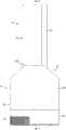
图1是加湿装置的前视图;Figure 1 is a front view of the humidifier;
图2是加湿装置的侧视图;Fig. 2 is a side view of the humidifying device;
图3是加湿装置的后视图;Figure 3 is a rear view of the humidifier;
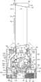
图4(a)是沿图1中的线A-A截取的侧截面视图,其中加湿装置的喷嘴被保持在本体上,且图4(b)是与图4(a)相似的视图,但是喷嘴被从本体释去;Fig. 4(a) is a side sectional view taken along line A-A in Fig. 1, wherein the nozzle of the humidifying device is held on the body, and Fig. 4(b) is a view similar to Fig. 4(a), but the nozzle is released from the body;
图5(a)是沿图1中的线B-B截取的顶部截面视图,且图5(b)是图5(a)中所示的区域P的放大视图;Figure 5(a) is a top sectional view taken along line B-B in Figure 1, and Figure 5(b) is an enlarged view of the region P shown in Figure 5(a);
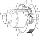
图6(a)是加湿装置的基座的从上方观察的透视图,其中基座的外壁被部分地去除,且图6(b)是与图6(a)类似的基座部分旋转之后的视图;Fig. 6(a) is a perspective view from above of the base of the humidifying device, wherein the outer wall of the base is partially removed, and Fig. 6(b) is after partial rotation of the base similar to Fig. 6(a) view;
图7(a)是安装在基座上的水箱的从上方观察的后透视图,其中手柄处于展开位置,且图7(b)是图7(a)中所示区域R的放大视图;Figure 7(a) is a rear perspective view from above of the tank mounted on the base with the handle in the deployed position, and Figure 7(b) is an enlarged view of the area R shown in Figure 7(a);
图8是沿图4(a)中的线D-D截取的顶部截面视图;Figure 8 is a top cross-sectional view taken along line D-D in Figure 4(a);
图9是沿图8中的线F-F截取的截面视图;Figure 9 is a cross-sectional view taken along line F-F in Figure 8;
图10是喷嘴的从下方观察的后透视图;Figure 10 is a rear perspective view of the nozzle from below;
图11是沿图4(a)中的线E-E截取的顶部截面视图;Figure 11 is a top sectional view taken along line E-E in Figure 4(a);
图12(a)是沿图2中的线C-C截取的前截面视图,其中加湿装置的喷嘴被保持在本体上,且图12(b)是与图12(a)相似的视图,但是喷嘴被从本体释去;Fig. 12(a) is a front sectional view taken along line C-C in Fig. 2, wherein the nozzle of the humidifying device is held on the body, and Fig. 12(b) is a view similar to Fig. 12(a), but the nozzle is released from the body;
图13是加湿装置的控制系统的示意性图示;以及Figure 13 is a schematic illustration of a control system of a humidifying device; and
图14是示出了加湿装置的操作步骤的流程图。Fig. 14 is a flowchart showing the operation steps of the humidifying device.
具体实施方式Detailed ways
图1到图3是风扇组件的外部视图。在这个实例中,风扇组件是加湿装置10的形式。总体上,加湿装置10包括本体12和喷嘴14,该本体12包括空气入口,空气穿过该空气入口进入加湿装置10,该喷嘴14是安装在本体12上的环形壳体的形式,喷嘴14包括用于从加湿装置10发射空气的多个空气出口。1 to 3 are external views of the fan assembly. In this example, the fan assembly is in the form of humidifying
喷嘴14被布置用于发射两股不同的空气流。喷嘴14包括后部区段16和被连接到后部区段16的前部区段18。每个区段16,18是环形的形状,且绕喷嘴14的孔眼20延伸。该孔眼20在中心延伸穿过喷嘴14以致每个区段16,18的中心位于孔眼20的轴线X上。The
在这个实施例中,每个区段16,18具有“跑道”形状,其中每个区段16,18包括位于孔眼20的相对侧上的两个大致直的区段,接合直的区段的上端的弯曲的上部区段和接合直的区段的下端的弯曲的下部区段。然而,区段16,18可具有任何期望的形状;例如区段16,18可以是圆形或椭圆形。在这个实施例中,喷嘴14的高度大于喷嘴的宽度,但喷嘴14可被布置以便喷嘴14的宽度大于喷嘴14的高度。In this embodiment, each
喷嘴14的每个区段16,18限定了一个流动路径,空气流中的相应的一股沿该流动路径穿过。在这个实施例中,喷嘴14的后部区段16限定了第一空气流动路径,第一空气流沿第一空气流动路径穿过喷嘴14,喷嘴14的前部区段18限定了第二空气流动路径,第二空气流沿第二空气流动路径穿过喷嘴14。Each
参考图4(a),喷嘴14的后部区段16包括连接到环形内部壳体区段24且绕其延伸的第一环形外部壳体区段22。每个壳体区段22、24绕孔眼轴线X延伸。每个壳体区段可由多个被连接部件形成,但在这个实施例中每个壳体区段22,24由相应的单个模制部件形成。如图5(a)和5(b)所示,第一外部壳体区段22的后部部分26向内朝向孔眼轴线X弯曲以限定喷嘴14的后端和孔眼20的后部部分。在装配中,第一外部壳体区段22的后部部分26的端部连接到内部壳体区段24的后端,例如使用粘合剂。第一外部壳体区段22包括管状基部28,该管状基部28限定了喷嘴14的第一空气入口30。Referring to FIG. 4( a ), the
喷嘴14的前部区段18也包括连接到环形前部壳体区段34且绕其延伸的第二环形外部壳体区段32。同样,每个壳体区段32、34绕孔眼轴线X延伸且可以由多个被连接部件形成,但在这个实施例中,每个壳体区段32、34是由相应的单个模制部件形成。在这个实施例中,前部壳体区段34包括连接到外部壳体区段22的前端的后部部分36和大致截头锥形形状且从后部部分36远离孔眼轴线X向外张开的前部部分38。前部壳体区段34可以与内部壳体区段24是一体的。第二外部壳体区段32是大致圆柱形形状且在第一外部壳体区段22和前部壳体区段34的前端之间延伸。第二外部壳体区段32包括管状基部40,该管状基部40限定了喷嘴14的第二空气入口42。The
壳体区段24、34一起限定了喷嘴14的第一空气出口44。第一空气出口44由内部壳体区段24和前部壳体区段34的后部部分36的重叠或相对的表面限定,从而第一空气出口44被布置成从喷嘴14的前端发射空气。第一空气出口44是环形槽的形式,其具有绕孔眼轴线X的相对不变的宽度,该宽度在0.5至5mm的范围内。在这个实例中,第一空气出口44具有约1mm的宽度。在内部壳体区段24、34由相应部件形成的情况下,间隔件46可沿第一空气出口44间隔开,用于促使壳体区段24、34的重叠部分分离以控制第一空气出口44的宽度。这些间隔件可与壳体区段24、34的任一个是一体的。在壳体区段24,34是由单个部件形成的情况下,间隔件46由翅片替代,该翅片沿第一空气出口44间隔开用于将内部壳体区段24和前部壳体区段34连接到一起。The
喷嘴14限定了第一环形内部通道48,该第一环形内部通道48用于将第一空气流从第一空气入口30运输到第一空气出口44。该第一内部通道48由第一外部壳体区段22的内表面和内部壳体区段24的内表面限定。锥形环形嘴部50引导第一空气流到第一空气出口44。嘴部50的锥形形状在空气从第一内部通道48流向第一空气出口44时提供了平稳、可控的空气加速。穿过喷嘴14的第一空气流动路径可因此被视为由第一空气入口30,第一内部通道48,嘴部50和第一空气出口40形成。The
前部壳体区段34限定了喷嘴14的多个第二空气出口52。该第二空气出口52也形成在喷嘴14的前端中,每个在孔眼20的相应侧上,例如通过模制或机械加工。每个第二空气出口52位于第一空气出口44的下游。在这个实例中,每个第二空气出口52是槽的形式,其具有相对不变的宽度,该宽度在0.5至5mm的范围内。在这个实例中,每个第二空气出口52具有约1mm的宽度。替代地,每个第二空气出口52可以是形成在喷嘴14的前部壳体区段34中的一排圆孔或槽的形式。The
喷嘴14限定了第二环形内部通道54,该第二环形内部通道54用于将第二空气流从第二空气入口42运输到第二空气出口52。该第二内部通道54由壳体区段32,34的内表面且由第一外部壳体区段22的外表面的前面部分限定。该第二内部通道54在喷嘴14内与第一内部通道48隔离开。穿过喷嘴14的第二空气流动路径可因此被视为由第二空气入口42,第二内部通道54和第二空气出口52形成。The
返回到图4(a),本体12为大体圆柱形形状。本体12包括基座56。该基座56具有外部外壁58,该外壁58是圆柱形形状,且该外壁58包括空气入口60。在这个实例中,该空气入口60包括形成在基座56的外壁58中的多个孔。基座56的前部部分可包括加湿装置10的用户接口。该用户接口示意性地示出在图13中,且在下面进行更详细地描述。用于供应电力到加湿装置10的主电源线(未显示)延伸穿过形成在基座56中的孔。Returning to Figure 4(a), the
该基座56包括第一空气通道62和第二空气通道64,该第一空气通道60用于将第一空气流运输到穿过喷嘴14的第一空气流动路径,该第二空气通道62用于将第二空气流运输到穿过喷嘴14的第二空气流动路径。The
第一空气通道62穿过基座56从空气入口60到喷嘴14的第一空气入口30。还参考图6(a)和6(b),基座56包括连接到外壁58的下端的底壁66,和大体圆柱形的内壁68,其通过凹入环形壁70连接到外壁58。内壁68从环形壁70向上延伸远离。在该实例中,外壁58、内壁68和环形壁70被形成为基座56的单个部件,但是替代地这些壁中的两个或多个可以形成为基座56的单独的部件。上壁被连接到内壁68的上端。上壁具有下部截头锥形区段72和上部圆柱形区段74,其中喷嘴14的基部28被插入到该上部圆柱形区段74中。A
内壁68绕叶轮76延伸,该叶轮64用于产生穿过第一空气通道62的第一空气流。在这个实例中,叶轮76是混流叶轮的形式。该叶轮76连接到从马达78向外延伸用于驱动叶轮76的旋转轴。在这个实施例中,马达78是直流无刷马达,其具有通过驱动电路80响应由用户选择的速度而变化的速度。电机78的最大速度优选地在5000至10000rpm的范围内。电机78被容纳在电机桶内,该桶包括连接到下部部分84的上部部分82。该马达桶的上部部分82包括为具有弯曲叶片的静止盘形式的扩散器86。该扩散器86位于喷嘴14的第一空气入口30的下方。The
电机桶位于大体为截头锥形的叶轮外壳88内,且被安装在其上。该叶轮外壳88被转而安装在从内壁68向内延伸的环形支撑件90上。环形进气构件92被连接到叶轮外壳88的底部用于引导空气流进入叶轮外壳88。环形密封构件94位于叶轮外壳88和环形支撑件90之间以阻止空气穿过叶轮外壳88的外表面周围到进气构件92。该环形支撑件90优选包括引导部分96,该引导部分96用于从驱动电路80引导电线到马达78。基座56还包括引导壁98,用于将空气流从空气入口60引导到进气构件92的进气口。The motor barrel is located within and mounted to the generally frusto-
第一空气通道62从空气入口60延伸到进气构件92的进气口。第一空气通道62进而延伸通过叶轮外壳88、内壁68的上端和上壁的区段72、74。The
环形腔体99定位在引导壁98和环形壁70之间。该腔体99具有定位在进气构件92和引导壁98之间的开口,使得腔体99朝向第一空气通道62敞开。该腔体99含有一个固定的空气囊,其用于降低在加湿装置10的使用期间产生的振动到本体12外表面的传递。An
第二空气通道64被布置为接收来自第一空气通道62的空气。第二空气通道64定位为与第一空气通道62相邻。第二空气通道64包括进气管100。参考图6(a)和6(b),进气管100由基座56的内壁68限定。进气管100定位为与第一空气通道62的一部分相邻,且在该实例中在其径向外部。进气管100大致平行于基座56的纵向轴线延伸,该纵向轴线与叶轮76的旋转轴线共线。进气管100具有定位在扩散器86下游并且从扩散器86径向向外的进气口102,以便于接收从扩散器86发出的空气流的一部分,其形成第二空气流。进气管100具有定位在其下端处的出气口104。The
第二空气通道64还包括出气管106,该出气管106被布置为运输第二空气流到喷嘴14的第二空气入口42。该第二空气流被沿大致相反的方向运输穿过进气管100和出气管106。出气管106包括定位在其下端的进气口108和定位在其上端的出气口。喷嘴14的第二外部壳体区段32的基部40被插入到出气管106的出气口,以从出气管106接收第二空气流。The
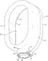
加湿装置10被配置为在第二空气流进入喷嘴14之前增加第二空气流的湿度。现参考图1到4(a)和图7,加湿装置10包括可移除地安装在基座56上的水箱120。基座56和水箱120一起形成加湿装置10的本体12。该水箱120具有圆柱形外壁122,该外壁122具有和本体12的基座56的外壁58相同的半径,以便当水箱120被安装在基座56上时本体12具有圆柱形外观。水箱120具有管状内壁124,当水箱120被安装在基座56上时,该内壁124围绕基座56的壁68、72、74。外壁122和内壁124与水箱120的环状上壁126和环状下壁128限定了用于储存水的环形体积。水箱120因此围绕叶轮76和马达78,且从而在水箱120被安装在基座56上时围绕第一空气通道62的至少一部分。当水箱120被安装在基座56上时,水箱120的下壁128接合基座56的外壁58和环形壁70的非凹入部分。The
该水箱120优选具有在从2至4升的范围内的容量。窗户130被提供在水箱120的外壁122上,以当水箱120被布置在基座56上时允许用户看见水箱120内的水位。The
参考图9,喷口132可移除地连接到水箱120的下壁128,例如通过配合的螺纹连接。在这个实例中,水箱120通过从基座56移走水箱120且将水箱120颠倒以便喷口132向上突出来填充。喷口132随后被从水箱120拧下,且水通过该喷口132从水箱120分离时暴露的孔被引进水箱120。一旦水箱120被装满,用户将喷口132重新连接到水箱120,将水箱120返回到其未颠倒取向并将水箱120放回基座56上。弹簧阀门134位于喷口132内,该阀门134用于当水箱120再次反转时防止水通过喷口132的排水口136泄漏。阀门134被朝向一位置偏压,在该位置阀门134的裙部接合喷口132的上表面以阻止水从水箱120进入喷口132。Referring to FIG. 9 , the
水箱120的上壁126包括用于将颠倒的水箱120支撑在工作表面、案台或其它支承表面上的一个或多个支撑件138。在该实例中,两个平行支撑件138被形成在上壁126的周边中,用于支撑颠倒的水箱120。The
还参考图6(a)、6(b)和8,基座56的外壁58、内壁68和环形壁70的凹入部分限定用于从水箱120接收水的水存储器140。基座56包括水处理腔室142,用于在来自水箱120的水进入水存储器140之前处理该水。水处理腔室142定位到水存储器140的一侧,环形壁70的凹入部分中。连接到环形壁70的盖件144包括水处理腔室142的水入口146和水出口148。在该实施例中,水入口146和水出口148的每一个包括多个孔。水出口148定位在盖件144的倾斜表面上,使得水出口148定位在水入口146的下方。盖件144由支撑销150支撑,该支撑销150从环形壁70向上延伸以接合盖件144的下表面。Referring also to FIGS. 6( a ), 6( b ) and 8 , the recessed portions of the
盖件144的向上延伸的销152定位在水入口146的孔之间。当水箱120安装在基座56上时,销152突出进入到喷口132,以向上推动阀134打开喷口132,由此允许水在重力作用下流动通过水入口146并进入水处理腔室142。当水处理腔室142装满水时,水流动通过水出口148并进入水存储器140。水处理腔室142容纳阈值抑制剂(threshold inhibitor),譬如聚磷酸盐(polyphosphate)材料的一个或多个滴或丸154,其在水流经水处理腔室142时被加入到水。提供固态的阈值抑制剂意味着阈值抑制剂随着与水处理腔室142中的水长期接触而缓慢溶解。由此,水处理腔室142包括屏障,其防止相对较大块的阈值抑制剂进入水存储器140。在该实例中,该屏障是位于环形壁70和水出口148之间的壁156的形式。The upwardly extending
在水存储器140中,环形壁70包括一对圆孔,每个用于暴露相应的压电换能器160。驱动电路80被配置为促使换能器160以雾化模式振动,以雾化位于水存储器140中的水。在雾化模式中,换能器160可以以频率f1超声振动,该频率f1可以在从1到2MHz的范围内。金属散热器162位于环形壁70和换能器160之间用于将热量传送离开换能器160。孔164形成在基座56的底壁64中,以散发从散热器162辐射的热量。环形密封构件在换能器160和散热器162之间形成不漏水的密封。如图6(a)和6(b)所示,环形壁70中的孔的周边部分166是凸起的,从而表现为一屏障,用于防止已经从水处理腔室142进入水存储器140的任意阈值抑制剂颗粒滞留在换能器160的暴露表面上。In the
水存储器140还包括紫外线辐射(UV)发生器,用于对存储在水存储器140中的水照射。在该实例中,UV发生器为位于UV可透过的管172内的UV灯170的形式,该管172定位在水存储器140中,使得当水存储器140装有水时,水围绕管172。管172定位在水存储器140的与换能器160相对的一侧上。一个或多个反射表面173可以被设置为邻近且优选地围绕管172,用于将从UV灯170发射的紫外线辐射发射到水存储器140中。水存储器140包括挡板174,其沿管172引导从水处理腔室142进入水存储器140的水,使得在使用期间,从水处理腔室142进入水存储器140的水在其被换能器160中的一个雾化之前被用紫外线辐射照射。The
磁液位传感器176位于水存储器140内用于检测水存储器140内的水的水位。取决于水箱120中的水的体积,水存储器140和水处理腔室142可以填充水到最大水位,该最大水位与销152的上表面大致共平面。进气管100的出气口104位于水存储器140内水的最大水位的上方,使得第二空气流在位于水存储器140内的水的表面上方进入水存储器140。The magnetic
出气管106的出气口108定位在换能器160上方,以从水存储器140接收加湿的空气流。该出气管106由水箱120限定。出气管106由水箱120的内壁124和弯曲壁180形成,内壁124绕该弯曲壁180延伸。The
基座56包括接近传感器182,用于检测水箱120已经被安装到基座56上。接近传感器182在图13中示意性地示出。接近传感器182可以是簧片开关的形式,其与定位在水箱120的下壁128上的磁体(未示出)相互作用,以检测水箱120存在还是不存在基座56上。如图7(a)、(b)和11所示,当水箱120安装在基座56上时,内壁124和弯曲壁180围绕基座56的上壁,以暴露上壁的上部圆柱形区段74的敞开上端。水箱120可包括手柄184,该手柄可帮助水箱120从基座56的移除。手柄184可以枢转地连接到水箱120,以便于可以相对于水箱120在收起位置和展开位置之间运动,在收起位置中,手柄184被容纳在水箱120的上壁126的凹入区段186内,而在展开位置中,手柄184被升起到水箱120的上壁126之上。参考图12(a)和12(b),一个或多个弹性元件188,譬如扭力弹簧,可以被提供以将手柄184朝向其展开位置偏压,如图7(a)和7(b)所示。The
当喷嘴14被安装在本体12上时,喷嘴14的第一外部壳体区段22的基部28被定位在基座56的上壁的上部圆柱形区段74的敞开端部之上,且喷嘴14的第二外部壳体区段32的基部40被定位在水箱120的出气管106的敞开上端之上。用户然后朝向本体12推压喷嘴14。如图10所示,销190形成在喷嘴14的第一外部壳体区段22的下表面上,第一外部壳体区段22的基部28的紧邻后方。当喷嘴14朝向本体12运动时,销190克服弹性元件188的偏压力朝向其收起位置推动手柄184。当喷嘴14的基部28、40被完全插入到本体12中时,环形密封构件192在基部28、40的端部和形成在基座56的上壁的上部圆柱形区段74中和出气管106中的环形台肩194之间形成气密密封。水箱120的上壁126具有凹形形状,使得当喷嘴14被安装在本体12上时,水箱120围绕喷嘴14的下部部分。这不仅可以允许水箱120的容量增加,还可以为加湿装置10提供紧凑的外观。When the
本体12包括用于将喷嘴14可释放地保持在本体12上的机构。图4(a)、11和12(a)示出了当喷嘴14被保持在本体12上时该机构的第一构造,而图4(b)和12(b)示出了当喷嘴14从本体12释放时该机构的第二构造。用于将喷嘴14可释放地保持在本体12上的机构包括定位在环形外壳202的直径相对侧上的一对制动器200。每一个制动器200具有大体L形横截面。每一个制动器200可以在用于保持喷嘴14在本体12上的展开位置和收起位置之间枢转运动。弹性元件204,譬如扭力弹簧,被定位在外壳202中用于将制动器200朝向它们的展开位置偏压。
在该实例中,水箱120包括用于将喷嘴14可释放地保持在本体12上的机构。外壳202包括一对直径相对的孔206,当水箱120被安装在基座56上时,孔206与形成在基座56的上壁的上部圆柱形区段74上的相似形状的孔208对准。喷嘴14的基部28的外表面包括一对直径相对的凹部210,其在喷嘴14被安装在本体12上时与孔206、208对准。当制动器200处于它们的展开位置时,制动器200的端部被弹性元件204推动穿过孔206、208,以进入喷嘴14的凹部210中。制动器200的端部接合喷嘴14的基部28的凹入外表面,以防止喷嘴14被从本体12脱离,例如如果加湿装置10被用户通过抓住喷嘴14而提起。In this example, the
本体12包括可按压卡扣件220,其可操作以通过将制动器200运动离开凹部210,而将该机构从第一构造运动到第二构造,从而将喷嘴14从本体12释放。卡扣件220被安装在外壳202中,用于绕一轴线枢转运动,该轴线正交于制动器200在其收起和展开位置之间枢转所绕的轴线。卡扣件220可以响应于用户按压定位在本体12上的按钮222而从如图4(a)、11和12(a)所示的收起位置运动到如图4(b)、7(a)、7(b)和12(b)所示的展开位置。在该实例中,按钮222定位在水箱120的上壁126上且位于卡扣件220的前部区段的上方。压缩弹簧或其它弹性元件可以被设置在卡扣件220的前部区段之下,用于将卡扣件220迫向收起位置。卡扣件220的旋转轴线定位为靠近卡扣件的前部区段,使得当卡扣件220向其展开位置运动时,卡扣件220迫使制动器200克服弹性元件204的偏压力枢转离开凹部210。The
本体12被配置为当用户释放按钮222时将卡扣件220保持在其展开位置。在该实例中,水箱120的外壳202包括楔形物224,当卡扣件220朝向其展开位置运动时,位于卡扣件220后部区段上的钩226在该楔形物上滑动。在展开位置,钩226的端部扣在楔形物224的锥形侧表面上以接合楔形物224的上表面,导致卡扣件220被保持在其展开位置。当钩226在楔形物224的上表面上运动时,钩226接合手柄184的底部,且迫使手柄184向上离开水箱120的凹入区段186。这进而导致手柄184将喷嘴14稍稍推离本体12,向用户提供喷嘴14已被从本体12释放的可视指示。作为对在水箱120和卡扣件220上具有协作以将卡扣件220保持在其展开位置的结构的替代,一个或多个磁体可以被使用以将卡扣件220保持在其展开位置。The
在其展开位置,卡扣件220将制动器200保持在其收起位置中,如图4(b)和12(b)所示,以允许用户将喷嘴14从该本体12移除。当喷嘴14被从本体12提起时,弹性元件188将手柄184迫到其展开位置。用户于是可以使用手柄184将水箱120从基座56提起,以允许水箱120按需要被填充或清洁。In its deployed position, the
一旦水箱120被装满或清洁,用户将水箱120放在基座56上,且然后将喷嘴14放回本体12上。当喷嘴14的基部28、40被推入本体12中时,喷嘴14上的销190接合手柄184并将手柄184推回到其在水箱120的凹入区段186内的收起位置。当手柄184运动到其收起位置时,它接合卡扣件220上的钩226并将钩226推离楔形物224的上表面以将卡扣件220从其展开位置释放。当钩226运动离开楔形物224时,弹性元件204将制动器推向其展开位置,以将喷嘴14保持在本体12上。当制动器200朝向其展开位置运动时,制动器200将卡扣件220移回到其收起位置。Once the
用于控制加湿装置的操作的用户接口位于本体12的基座56的外壁58上。图13示意性地示出了用于加湿装置10的控制系统,该控制系统包括这个用户接口和加湿装置10的其他电气部件。在这个实施例中,用户接口包括多个用户可操作按钮240a、240b和240c,和显示器242。该第一按钮240a用于激活或关闭马达78,第二按钮240b用于设定马达78的速度,由此设定叶轮76的旋转速度。第三按钮240c用于设定加湿装置10所在其中的环境(如房间,办公室或其他家庭环境)的相对湿度的期望水平。例如,期望的相对湿度的水平可通过第三按钮240c的重复促动在20°C处的30%至80%的范围内选择。该显示器242提供了当前选择的相对湿度水平的指示。A user interface for controlling the operation of the humidifying device is located on the
用户接口还包括用户接口电路244,该用户接口电路144根据按钮中的一个的促动输出控制信号到驱动电路80,并接收由驱动电路80输出的控制信号。用户接口还可包括一个或多个发光二级管(LED),该发光二级管用于根据加湿装置的状态提供视觉警告。例如,第一LED246a可由驱动电路80点亮指示水箱120已经排空,如通过驱动电路80接收的来自液位传感器176的信号所指示。The user interface also includes a
湿度传感器248也被提供用于检测外部环境中的空气的相对湿度,且用于供应检测到的相对湿度的指示信号到驱动电路80。在这个实施例中,该湿度传感器248可位于空气入口60的紧邻后方以检测被抽吸进入加湿装置10中的空气流的相对湿度。用户接口可包括第二LED246b,当来自湿度传感器248的输出指示进入加湿装置10中的空气流的相对湿度HD等于或大于用户设定的期望相对湿度HS时,该LED246b由驱动电路80点亮。A
还参考图14,为了操作加湿装置10,用户促动第一按钮240a。按钮240a的该操作被传递到驱动电路80,响应于此,驱动电路80促动UV灯170以对存储在水存储器140中的水照射。在该实例中,驱动电路80同时激活马达78以旋转叶轮76。叶轮76的旋转导致空气穿过空气入口60被抽吸进入本体12中。空气流穿过叶轮外壳88和扩散器86。在扩散器86的下游,从扩散器86发射的空气的一部分穿过进气口102进入进气管100,而从扩散器86发射的空气的剩余部分被沿第一空气通道62输送到喷嘴14的第一空气入口30。叶轮76和马达78可由此被视为产生第一空气流,该第一空气流通过第一空气通道62被运输到喷嘴14且通过第一空气入口30进入喷嘴14。Referring also to Fig. 14, to operate the
第一空气流在喷嘴14的后部区段16的基部处进入第一内部通道48。在第一内部通道48的基部处,空气流被分为两股气流,该两股气流绕喷嘴14的孔眼20沿相反方向行进。当气流穿过第一内部通道48时,空气进入喷嘴14的嘴部50。进入嘴部50中的该空气流优选绕喷嘴14的孔眼20大致均匀。该嘴部50引导空气流朝向喷嘴14的第一空气出口44,空气流从第一空气出口44从加湿装置10发射。The first air flow enters the first
该空气流从第一空气出口40发射导致次空气流通过卷吸来自外部环境的空气产生,特别地来自第一空气出口44周围区域和来自喷嘴14的后面周围。这些次空气流的一些穿过喷嘴14的孔眼20,而该次空气流的剩余部分被卷吸在从喷嘴14的前部中的第一空气出口发射的空气流内。This air flow emitted from the
如上所述,随着叶轮76的旋转,空气穿过进气管100的进气口102进入第二空气通道64,以形成第二空气流。第二空气流流经进气管100且被通过出气口104发射到存储在水存储器140中的水的上方。该第二空气流从出气口104的发射搅动存储在水存储器140中的水以产生沿和绕UV灯170的水运动,增加被UV灯170照射的水的体积。在存储的水中阈值抑制剂的存在导致阈值抑制剂的薄层形成在管172和换能器160的暴露到存储的水的表面上,抑制水垢在这些表面上的沉淀。这可以延长换能器160的工作寿命并抑制由UV灯170对存储水的照射的任何能量降级。As described above, as the
除了通过第二空气流140搅动存储在水存储器140中的水之外,搅动还可以通过搅动模式下的换能器160的振动来执行,该搅动模式的振动不足以使存储的水雾化。例如取决于基座56的换能器160的尺寸和数量,存储的水的搅动可以仅通过换能器160以降低的第二频率f2和/或以降低的幅度、或以不同的占空比的振动来执行。在该情况下,驱动电路80可以配置为在通过UV灯170对存储的水照射的同时,以该搅动模式促动换能器160的振动。In addition to agitating the water stored in the
该存储水的搅动和照射持续一时间段,该时间段足以使水存储器140中的细菌水平降低期望数量。在该实例中,水存储器140具有200ml的最大容量,且存储水的搅动和照射持续60秒的时间段,然后存储水的雾化开始。该时间段的持续时间可以取决于例如存储水的搅动程度、水存储器140的容量以及存储水的照射强度而加长或缩短,且从而取决于这些变量,该时间段的持续时间可以采取在10到300秒范围内的任何值,以实现存储水中的细菌数量的期望降低。The agitation and irradiation of the stored water is for a period of time sufficient to reduce the bacteria level in the
在该时间段结束时,驱动电路80促动换能器160以雾化模式振动,以雾化存储在水存储器140中的水。这造成位于水存储器140内的水的上方的空气中的水滴。在存储水被换能器160的振动独自预先搅动的情况下,马达78在该时间段结束时也被启动。At the end of this time period, the
随着水存储器140内的水雾化,水存储器140不断地被经由水处理腔室142接收自水箱120的水重新装满,以便水存储器140内的水的水位保持大致不变同时水箱120内的水的水位逐渐下降。当水从水处理腔室142(在其中阈值抑制剂被加入水)进入水存储器140时,它被壁174引导以沿着管172流动,使得它在被雾化之前被用紫外线辐射照射。As the water in the
随着叶轮76的旋转,空中的水滴被夹带在从进气管100的出气口104发射的第二空气流中。该目前湿的第二空气流向上穿过第二空气通道64的出气管106到喷嘴14的第二空气入口42,且进入喷嘴14的前部区段18内的第二内部通道54。As the
在第二内部通道54的基座处,第二空气流被分成两股气流,该两股气流绕喷嘴14的孔眼20沿相反方向行进。当该气流穿过第二内部通道54时,每股气流从位于第一空气出口44前面的喷嘴14的前端中的第二空气出口52中的相应一个发射。该被发射的第二空气流在通过第一空气流从喷嘴14的发射而产生的空气流内被运输远离加湿装置10,从而使湿气流被在距加湿装置10几米的距离处迅速体验到。At the base of the second
湿空气流从喷嘴14发射直到由湿度传感器248检测到进入加湿装置10的空气流的相对湿度HD比用户使用第三按钮240c选定的相对湿度水平HS高在20°C处的1%为止。于是湿空气流从喷嘴14的发射可通过驱动电路80,优选通过改变换能器160的振动模式,而终止。例如,换能器160的振动频率可以被降低到频率f3,其中f1>f3≥0,在该频率f3之下存储水的雾化没有被执行。替代地,换能器160振动的幅度可以被降低。可选择地,马达78也可被停止从而没有空气流从喷嘴14发射。然而,当湿度传感器248定位为紧密靠近马达78时,最好马达78继续运行以避免在湿度传感器248的局部环境中的不期望的温度波动。此外,优选继续运行马达78以继续搅动存储在水存储器140中的水。UV灯170的操作也继续。The stream of humid air is emitted from the
作为终止从加湿装置10发射湿空气流的结果,通过湿度传感器248检测到的相对湿度HD开始下降。一旦湿度传感器248的局部环境的空气的相对湿度下降到比用户选定的相对湿度水平HS低在20°C处的1%,驱动电路80以雾化模式重新启动换能器160的振动。如果马达78被停止,驱动电路80同时重新启动马达78。如之前,湿空气流从喷嘴14发射直到湿度传感器248检测到的相对湿度HD比用户选定的相对湿度水平HS高在20°C处的1%。As a result of the cessation of the flow of humid air emitted from the
用于保持检测到的湿度水平在用户选择的水平附近的这个换能器160(和可选择地马达78)的促动程序继续进行直到按钮240a再次被促动,或直到接收自水位传感器176的信号指示水存储器140内的水的水位已经下降到最小水位以下。如果按钮240a被促动,或一旦从水位传感器176接收到该信号,驱动电路80关闭马达78、换能器160和UV灯170以关闭加湿装置。驱动电路80还响应于从接近传感器182接收的指示水箱120已经被从基座56移除的信号而关闭加湿装置10的这些部件。The actuation routine for this transducer 160 (and optionally the motor 78) for maintaining the detected humidity level near the user-selected level continues until the
Claims (17)
Translated fromChineseApplications Claiming Priority (2)
| Application Number | Priority Date | Filing Date | Title |
|---|---|---|---|
| GB1203894.9 | 2012-03-06 | ||
| GB1203894.9AGB2500009B (en) | 2012-03-06 | 2012-03-06 | A Humidifying Apparatus |
Publications (2)
| Publication Number | Publication Date |
|---|---|
| CN103306948Atrue CN103306948A (en) | 2013-09-18 |
| CN103306948B CN103306948B (en) | 2016-06-29 |
Family
ID=46003177
Family Applications (2)
| Application Number | Title | Priority Date | Filing Date |
|---|---|---|---|
| CN2013201012280UExpired - LifetimeCN203272072U (en) | 2012-03-06 | 2013-03-06 | Humidifying device |
| CN201310070642.4AExpired - Fee RelatedCN103306948B (en) | 2012-03-06 | 2013-03-06 | Damping device |
Family Applications Before (1)
| Application Number | Title | Priority Date | Filing Date |
|---|---|---|---|
| CN2013201012280UExpired - LifetimeCN203272072U (en) | 2012-03-06 | 2013-03-06 | Humidifying device |
Country Status (6)
| Country | Link |
|---|---|
| US (1) | US20130234347A1 (en) |
| EP (1) | EP2636962A3 (en) |
| JP (1) | JP5572732B2 (en) |
| CN (2) | CN203272072U (en) |
| GB (1) | GB2500009B (en) |
| TW (1) | TWM472758U (en) |
Families Citing this family (52)
| Publication number | Priority date | Publication date | Assignee | Title |
|---|---|---|---|---|
| CN202056982U (en) | 2009-03-04 | 2011-11-30 | 戴森技术有限公司 | Humidifying device |
| BR112014001474A2 (en) | 2011-07-27 | 2017-02-21 | Dyson Technology Ltd | fan assembly |
| GB2493506B (en) | 2011-07-27 | 2013-09-11 | Dyson Technology Ltd | A fan assembly |
| GB201119500D0 (en) | 2011-11-11 | 2011-12-21 | Dyson Technology Ltd | A fan assembly |
| GB2512192B (en) | 2012-03-06 | 2015-08-05 | Dyson Technology Ltd | A Humidifying Apparatus |
| GB2500010B (en) | 2012-03-06 | 2016-08-24 | Dyson Technology Ltd | A humidifying apparatus |
| GB2500009B (en)* | 2012-03-06 | 2015-08-05 | Dyson Technology Ltd | A Humidifying Apparatus |
| GB2500012B (en) | 2012-03-06 | 2016-07-06 | Dyson Technology Ltd | A Humidifying Apparatus |
| GB2500011B (en) | 2012-03-06 | 2016-07-06 | Dyson Technology Ltd | A Humidifying Apparatus |
| RU2606194C2 (en) | 2012-03-06 | 2017-01-10 | Дайсон Текнолоджи Лимитед | Fan unit |
| GB2500017B (en) | 2012-03-06 | 2015-07-29 | Dyson Technology Ltd | A Humidifying Apparatus |
| AU350181S (en) | 2013-01-18 | 2013-08-15 | Dyson Technology Ltd | Humidifier or fan |
| AU350140S (en) | 2013-01-18 | 2013-08-13 | Dyson Technology Ltd | Humidifier or fan |
| BR302013003358S1 (en) | 2013-01-18 | 2014-11-25 | Dyson Technology Ltd | CONFIGURATION APPLIED ON HUMIDIFIER |
| SG11201505665RA (en) | 2013-01-29 | 2015-08-28 | Dyson Technology Ltd | A fan assembly |
| GB2510195B (en) | 2013-01-29 | 2016-04-27 | Dyson Technology Ltd | A fan assembly |
| BR302013004394S1 (en) | 2013-03-07 | 2014-12-02 | Dyson Technology Ltd | CONFIGURATION APPLIED TO FAN |
| CA152655S (en) | 2013-03-07 | 2014-05-20 | Dyson Technology Ltd | Fan |
| CA152658S (en) | 2013-03-07 | 2014-05-20 | Dyson Technology Ltd | Fan |
| CA152656S (en) | 2013-03-07 | 2014-05-20 | Dyson Technology Ltd | Fan |
| USD729372S1 (en) | 2013-03-07 | 2015-05-12 | Dyson Technology Limited | Fan |
| CA152657S (en) | 2013-03-07 | 2014-05-20 | Dyson Technology Ltd | Fan |
| CA154722S (en) | 2013-08-01 | 2015-02-16 | Dyson Technology Ltd | Fan |
| TWD172707S (en) | 2013-08-01 | 2015-12-21 | 戴森科技有限公司 | A fan |
| CA154723S (en) | 2013-08-01 | 2015-02-16 | Dyson Technology Ltd | Fan |
| GB2518638B (en) | 2013-09-26 | 2016-10-12 | Dyson Technology Ltd | Humidifying apparatus |
| GB2528704A (en) | 2014-07-29 | 2016-02-03 | Dyson Technology Ltd | Humidifying apparatus |
| GB2528708B (en) | 2014-07-29 | 2016-06-29 | Dyson Technology Ltd | A fan assembly |
| GB2528709B (en) | 2014-07-29 | 2017-02-08 | Dyson Technology Ltd | Humidifying apparatus |
| TWD179707S (en)* | 2015-01-30 | 2016-11-21 | 戴森科技有限公司 | A fan |
| TWD173931S (en)* | 2015-01-30 | 2016-02-21 | 戴森科技有限公司 | A fan |
| TWD173930S (en)* | 2015-01-30 | 2016-02-21 | 戴森科技有限公司 | A fan |
| TWD173929S (en)* | 2015-01-30 | 2016-02-21 | 戴森科技有限公司 | A fan |
| TWD173928S (en)* | 2015-01-30 | 2016-02-21 | 戴森科技有限公司 | A fan |
| TWD173932S (en)* | 2015-01-30 | 2016-02-21 | 戴森科技有限公司 | A fan |
| KR101769817B1 (en)* | 2015-10-30 | 2017-08-30 | 엘지전자 주식회사 | apparatus for both humidification and air cleaning |
| USD804007S1 (en)* | 2015-11-25 | 2017-11-28 | Vornado Air Llc | Air circulator |
| CN105841231B (en)* | 2016-03-28 | 2018-10-23 | 广东美的制冷设备有限公司 | Air conditioner indoor unit |
| CN106500226A (en)* | 2016-12-19 | 2017-03-15 | 长江大学 | A kind of ultrasonic air conditioner type health care bladeless fan |
| US11384956B2 (en) | 2017-05-22 | 2022-07-12 | Sharkninja Operating Llc | Modular fan assembly with articulating nozzle |
| CN108224653B (en)* | 2017-12-30 | 2024-05-14 | 广东泰坦智能电器有限公司 | A ring-type spray humidifier |
| US10926210B2 (en) | 2018-04-04 | 2021-02-23 | ACCO Brands Corporation | Air purifier with dual exit paths |
| USD913467S1 (en) | 2018-06-12 | 2021-03-16 | ACCO Brands Corporation | Air purifier |
| GB201900020D0 (en) | 2019-01-02 | 2019-02-13 | Dyson Technology Ltd | Air treatment apparatus |
| GB201900018D0 (en) | 2019-01-02 | 2019-02-13 | Dyson Technology Ltd | Air treatment apparatus |
| GB201900016D0 (en) | 2019-01-02 | 2019-02-13 | Dyson Technology Ltd | Air treatment apparatus |
| CN111928400B (en)* | 2020-09-13 | 2021-01-12 | 深圳市几素科技有限公司 | Air humidifier |
| USD1057918S1 (en) | 2021-06-23 | 2025-01-14 | Sharkninja Operating Llc | Air purifier |
| KR102585889B1 (en) | 2021-09-15 | 2023-10-06 | 엘지전자 주식회사 | Blower |
| USD1079922S1 (en) | 2022-11-30 | 2025-06-17 | Vornado Air, Llc | Tower fan |
| US20250213029A1 (en) | 2023-01-19 | 2025-07-03 | Sharkninja Operating Llc | Hair care appliance with powered attachment |
| US20240245190A1 (en) | 2023-01-19 | 2024-07-25 | Sharkninja Operating Llc | Identification of hair care appliance attachments |
Citations (8)
| Publication number | Priority date | Publication date | Assignee | Title |
|---|---|---|---|---|
| US2488467A (en)* | 1947-09-12 | 1949-11-15 | Lisio Salvatore De | Motor-driven fan |
| US5483616A (en)* | 1994-12-21 | 1996-01-09 | Duracraft Corporation | Humidifier tank with improved handle |
| US5783117A (en)* | 1997-01-09 | 1998-07-21 | Hunter Fan Company | Evaporative humidifier |
| CN201739198U (en)* | 2010-05-27 | 2011-02-09 | 李德正 | Bladeless electric fan |
| GB2473037A (en)* | 2009-08-28 | 2011-03-02 | Dyson Technology Ltd | Humidifying apparatus comprising a fan and a humidifier with a plurality of transducers |
| CN102095236A (en)* | 2011-02-17 | 2011-06-15 | 曾小颖 | Ventilation device |
| CN102287357A (en)* | 2011-09-02 | 2011-12-21 | 应辉 | Fan assembly |
| CN203272072U (en)* | 2012-03-06 | 2013-11-06 | 戴森技术有限公司 | Humidifying device |
Family Cites Families (12)
| Publication number | Priority date | Publication date | Assignee | Title |
|---|---|---|---|---|
| JPH0748020B2 (en)* | 1989-06-16 | 1995-05-24 | 三洋電機株式会社 | humidifier |
| JPH0612467Y2 (en)* | 1989-10-05 | 1994-03-30 | 三洋電機株式会社 | humidifier |
| JPH04106440U (en)* | 1991-02-19 | 1992-09-14 | 積水化成品工業株式会社 | humidifier |
| JP2000055419A (en)* | 1998-08-11 | 2000-02-25 | Aiwa Co Ltd | Water supply mechanism and humidifier using the same |
| JP3094083U (en)* | 2002-11-15 | 2003-05-30 | 豐元機電有限公司 | Humidifier structure |
| US8985105B2 (en)* | 2005-10-21 | 2015-03-24 | Compumedics Medical Innovation Pty Ltd | Apparatus for delivery of pressurised gas |
| JP2009275925A (en)* | 2008-05-12 | 2009-11-26 | Tiger Vacuum Bottle Co Ltd | Humidifier |
| JP2010046411A (en)* | 2008-08-25 | 2010-03-04 | Panasonic Electric Works Co Ltd | Mist generator |
| WO2010090045A1 (en)* | 2009-02-09 | 2010-08-12 | パナソニック株式会社 | Electric heater |
| GB2468312A (en)* | 2009-03-04 | 2010-09-08 | Dyson Technology Ltd | Fan assembly |
| CN202056982U (en)* | 2009-03-04 | 2011-11-30 | 戴森技术有限公司 | Humidifying device |
| GB2482548A (en)* | 2010-08-06 | 2012-02-08 | Dyson Technology Ltd | A fan assembly with a heater |
- 2012
- 2012-03-06GBGB1203894.9Apatent/GB2500009B/ennot_activeExpired - Fee Related
- 2013
- 2013-02-13EPEP13155040.2Apatent/EP2636962A3/ennot_activeWithdrawn
- 2013-03-05TWTW102203975Upatent/TWM472758U/ennot_activeIP Right Cessation
- 2013-03-05USUS13/786,313patent/US20130234347A1/ennot_activeAbandoned
- 2013-03-06CNCN2013201012280Upatent/CN203272072U/ennot_activeExpired - Lifetime
- 2013-03-06CNCN201310070642.4Apatent/CN103306948B/ennot_activeExpired - Fee Related
- 2013-03-06JPJP2013062875Apatent/JP5572732B2/ennot_activeExpired - Fee Related
Patent Citations (8)
| Publication number | Priority date | Publication date | Assignee | Title |
|---|---|---|---|---|
| US2488467A (en)* | 1947-09-12 | 1949-11-15 | Lisio Salvatore De | Motor-driven fan |
| US5483616A (en)* | 1994-12-21 | 1996-01-09 | Duracraft Corporation | Humidifier tank with improved handle |
| US5783117A (en)* | 1997-01-09 | 1998-07-21 | Hunter Fan Company | Evaporative humidifier |
| GB2473037A (en)* | 2009-08-28 | 2011-03-02 | Dyson Technology Ltd | Humidifying apparatus comprising a fan and a humidifier with a plurality of transducers |
| CN201739198U (en)* | 2010-05-27 | 2011-02-09 | 李德正 | Bladeless electric fan |
| CN102095236A (en)* | 2011-02-17 | 2011-06-15 | 曾小颖 | Ventilation device |
| CN102287357A (en)* | 2011-09-02 | 2011-12-21 | 应辉 | Fan assembly |
| CN203272072U (en)* | 2012-03-06 | 2013-11-06 | 戴森技术有限公司 | Humidifying device |
Also Published As
| Publication number | Publication date |
|---|---|
| JP5572732B2 (en) | 2014-08-13 |
| CN103306948B (en) | 2016-06-29 |
| TWM472758U (en) | 2014-02-21 |
| GB2500009B (en) | 2015-08-05 |
| EP2636962A2 (en) | 2013-09-11 |
| CN203272072U (en) | 2013-11-06 |
| US20130234347A1 (en) | 2013-09-12 |
| EP2636962A3 (en) | 2013-12-11 |
| GB201203894D0 (en) | 2012-04-18 |
| JP2013185818A (en) | 2013-09-19 |
| GB2500009A (en) | 2013-09-11 |
Similar Documents
| Publication | Publication Date | Title |
|---|---|---|
| CN103306944B (en) | Damping device | |
| CN103306945B (en) | Damping device | |
| CN103306946B (en) | Fan component | |
| CN103306948B (en) | Damping device | |
| CN103306949A (en) | Humidifying apparatus | |
| GB2500007A (en) | Bladeless fan with removable nozzle | |
| GB2500008A (en) | Bladeless fan with removable nozzle |
Legal Events
| Date | Code | Title | Description |
|---|---|---|---|
| C06 | Publication | ||
| PB01 | Publication | ||
| C10 | Entry into substantive examination | ||
| SE01 | Entry into force of request for substantive examination | ||
| C14 | Grant of patent or utility model | ||
| GR01 | Patent grant | ||
| CF01 | Termination of patent right due to non-payment of annual fee | Granted publication date:20160629 Termination date:20200306 | |
| CF01 | Termination of patent right due to non-payment of annual fee |