CN103286771A - Spatial three-rotational-freedom parallel connecting mechanism - Google Patents
Spatial three-rotational-freedom parallel connecting mechanismDownload PDFInfo
- Publication number
- CN103286771A CN103286771ACN201310195848XACN201310195848ACN103286771ACN 103286771 ACN103286771 ACN 103286771ACN 201310195848X ACN201310195848X ACN 201310195848XACN 201310195848 ACN201310195848 ACN 201310195848ACN 103286771 ACN103286771 ACN 103286771A
- Authority
- CN
- China
- Prior art keywords
- connecting rod
- frame
- freedom
- saddle
- moving platform
- Prior art date
- Legal status (The legal status is an assumption and is not a legal conclusion. Google has not performed a legal analysis and makes no representation as to the accuracy of the status listed.)
- Pending
Links
- 238000009434installationMethods0.000abstractdescription3
- 238000004519manufacturing processMethods0.000abstractdescription3
- 238000010586diagramMethods0.000description3
- 239000012636effectorSubstances0.000description3
- 238000000034methodMethods0.000description3
- 238000013519translationMethods0.000description3
- 230000009286beneficial effectEffects0.000description1
- 238000013461designMethods0.000description1
- 238000012986modificationMethods0.000description1
- 230000004048modificationEffects0.000description1
- 238000012545processingMethods0.000description1
Images

Landscapes
- Transmission Devices (AREA)
Abstract
Translated fromChinese
Description
Translated fromChinese技术领域technical field
本发明涉及一种并联机构,特别是涉及一种可实现三转动自由度作业功能的并联机构。The invention relates to a parallel mechanism, in particular to a parallel mechanism capable of realizing the operation function of three rotation degrees of freedom.
背景技术Background technique
根据专利ZL200910054381、ZL201210182195.7等可知,现有的空间三转动自由度并联机构,主要有两种实现形式:其一,机架与末端动平台之间通过两(或三)条无约束运动支链及一条三自由度恰约束支链相连,支链上均设置驱动装置,每条支链可单独在驱动装置的驱动下运动,使动平台相对于机架产生空间三转动;其二,采用两自由度并联机构与单自由度转头串联的形式。According to patents ZL200910054381, ZL201210182195.7, etc., the existing three-rotation-degree-of-freedom parallel mechanism in space mainly has two realization forms: first, two (or three) unconstrained motion supports are used between the frame and the terminal moving platform. Chain and a three-degree-of-freedom just-constrained branch chain are connected, and driving devices are installed on the branch chains, and each branch chain can move independently under the drive of the driving device, so that the moving platform generates three spatial rotations relative to the frame; secondly, using A form in which a two-degree-of-freedom parallel mechanism is connected in series with a single-degree-of-freedom rotor.
此类机构存在的不足是:各支链结构组成复杂,支链内各运动副布置较困难,对加工与装配要求苛刻,制造成本高,末端执行器惯性大,无约束支链与恰约束支链负载相差大,影响机构的动态性能。The shortcomings of this type of mechanism are: the structure of each branch chain is complex, the arrangement of the kinematic pairs in the branch chain is difficult, the requirements for processing and assembly are harsh, the manufacturing cost is high, the inertia of the end effector is large, the unconstrained branch chain and the precisely constrained branch The chain load varies greatly, which affects the dynamic performance of the mechanism.
发明内容Contents of the invention
本发明的目的在于克服已有技术的缺点,提供一种结构简单、安装方便、承载能力高且工作空间大,可实现末端执行器空间三转动的一种空间三转动自由度并联机构。The purpose of the present invention is to overcome the shortcomings of the prior art, and provide a parallel mechanism with three degrees of freedom in space, which has simple structure, convenient installation, high bearing capacity and large working space, and can realize three rotations in space of the end effector.
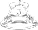
本发明的一种空间三转动自由度并联机构,它包括机架,在所述的机架的上方设置有一个动平台,所述机架呈圆形布置结构,在所述的机架上设置有圆形导向滑轨,第一、第二、第三主动支链空间三对称分布于所述机架与动平台之间,所述的第一、第二、第三主动支链具有相同的结构,每一个主动支链包括与导向滑轨相连构成移动副的滑鞍,所述滑鞍与连杆的一端活动相连,所述连杆的另一端通过具有三转动自由度的铰链与所述动平台相连。A space three-rotation-degree-of-freedom parallel mechanism of the present invention comprises a frame, a moving platform is arranged above the frame, the frame is arranged in a circular structure, and a moving platform is arranged on the frame There are circular guide rails, and the first, second, and third active branch chains are three-symmetrically distributed between the frame and the moving platform. The first, second, and third active branch chains have the same structure, each active branch chain includes a sliding saddle connected with a guide rail to form a moving pair, the saddle is movably connected with one end of the connecting rod, and the other end of the connecting rod is connected to the connected to the moving platform.
本发明的空间三自由度并联机构有益效果是:模块化结构设计,结构简单,便于制造安装,姿态能力强,动态性能好。当驱动装置驱动第一、第二、第三主动支链产生相同的运动时,动平台实现垂直于动平台法线方向的转动,且最大转角可达到360°,当驱动装置驱动三条主动支链产生不同的输入时,动平台可实现另外两个方向的转动,故本发明机构具有空间三转动自由度,且具有较大的姿态工作空间。The beneficial effects of the space three-degree-of-freedom parallel mechanism of the present invention are: modular structure design, simple structure, easy manufacture and installation, strong posture capability and good dynamic performance. When the driving device drives the first, second and third active branch chains to produce the same motion, the moving platform can rotate perpendicular to the normal direction of the moving platform, and the maximum rotation angle can reach 360°. When the driving device drives the three active branch chains When different inputs are generated, the moving platform can realize rotation in two other directions, so the mechanism of the present invention has three rotational degrees of freedom in space, and has a larger attitude work space.
附图说明Description of drawings
图1为本发明的一种空间三转动自由度并联机构的结构示意图;Fig. 1 is a structural schematic diagram of a parallel mechanism with three rotational degrees of freedom in space according to the present invention;
图2是图1所示的并联机构的工作结构示意图;Fig. 2 is a schematic diagram of the working structure of the parallel mechanism shown in Fig. 1;
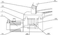
图3是图2所示的并联机构的工作结构中的驱动装置部分示意图。Fig. 3 is a partial schematic diagram of the driving device in the working structure of the parallel mechanism shown in Fig. 2 .
具体实施方式Detailed ways
下面结合附图和具体实施例对本发明作以详细描述。The present invention will be described in detail below in conjunction with the accompanying drawings and specific embodiments.
如附图所示本发明的一种空间三转动自由度并联机构,它包括机架7,在所述的机架的上方设置有一个动平台1,所述机架呈圆形,在所述的机架上设置有圆形导向滑轨,第一、第二、第三主动支链空间三对称即彼此之间空间对称的分布于所述机架与动平台之间,所述的第一、第二、第三主动支链具有相同的结构,每一个主动支链包括与导向滑轨相连构成移动副的滑鞍,所述滑鞍与连杆的一端活动相连,所述连杆的另一端通过具有三转动自由度的铰链与所述动平台相连。As shown in the accompanying drawings, a space three-rotation degree of freedom parallel mechanism of the present invention includes a
优选的所述滑鞍与连杆的一端通过转动副相连,所述转动副轴线始终与移动副的瞬时轴线方向一致。当然也可以在滑鞍上固定连接一个滑轨,连杆的一端为滑块,所述的滑块与滑轨滑动相连构成第一移动副,所述的滑块轴线与连杆轴线共线同样可实现末端执行器的空间三转动。Preferably, the saddle is connected with one end of the connecting rod through a rotating pair, and the axis of the rotating pair is always in the same direction as the instantaneous axis of the moving pair. Of course, a slide rail can also be fixedly connected to the saddle, and one end of the connecting rod is a slide block, and the slide block is slidably connected with the slide rail to form the first moving pair, and the axis of the slide block is collinear with the axis of the connecting rod. The three-dimensional rotation of the end effector can be realized.
优选的所述的具有三转动自由度的铰链为球铰链。Preferably, the hinge with three rotational degrees of freedom is a ball hinge.
下面再结合每一幅图对本发明加以详细说明:The present invention is described in detail below again in conjunction with each figure:
图1中机架7呈圆形布置结构,所述圆形机架7上设有圆形导向滑轨,所述第一主动支链、第二主动支链、第三主动支链分布于所述机架7与动平台1之间,所述机架7与所述第一主动支链、第二主动支链、第三主动支链通过移动副相连。所述移动副可采用附图所示导轨滑块结构,即机架7上固定连接圆形导向滑轨,主动支链2的一端设置滑鞍,所述圆形导向滑轨与所述滑鞍配合形成移动副。所述移动副可采用伺服电机加小/大伞齿轮的驱动方式,也可采用液压等结构作为驱动方式。
所述具有三转动自由度的铰链也可采用其他具有三转动能力的铰链形式,如三个两两正交的转动副组成的铰链等。The hinge with three rotational degrees of freedom may also adopt other forms of hinges with three rotational capabilities, such as a hinge composed of three two-by-two orthogonal rotational pairs.
所述第一主动支链由第一滑鞍6A、第一转动副5A、第一连杆4A、第一球铰链3A组成。第一滑鞍6A与机架圆形导向滑轨构成移动副,第一滑鞍6A通过第一转动副5A与第一连杆4A的一端相连,第一转动副5A轴线始终与所述移动副的瞬时轴线方向一致,第一连杆4A的另一端通过第一球铰链3A与动平台1相连。The first active branch chain is composed of a first sliding
所述第二主动支链由第二滑鞍6B、第二转动副5B、第二连杆4B、第二球铰链组成。第二滑鞍6B与机架圆形导向滑轨构成移动副,第二滑鞍6B通过第二转动副5B与第二连杆4B的一端相连,第二转动副5B轴线始终与所述移动副的瞬时轴线方向一致,第二连杆4B的另一端通过第二球铰链与动平台1相连。The second active branch chain is composed of a second sliding
所述第三主动支链由第三滑鞍6C、第三转动副5C、第三连杆4C、第三球铰链3C组成。第三滑鞍6C与机架圆形导向滑轨构成移动副,第三滑鞍6C通过第三转动副5C与第三连杆4C的一端相连,第三转动副5C轴线始终与所述移动副的瞬时轴线方向一致,第三连杆4C的另一端通过第三球铰链3C与动平台1相连。The third active branch chain is composed of a
本装置的运动过程为:The movement process of this device is:
如图2和3所示,移动副作为机构的驱动装置,该空间三转动并联机构采用伺服电机加小/大伞齿轮的驱动方式。第一大伞齿轮10A与滑鞍固定相连,伺服电机8经由第一小伞齿轮9A将转动传至第一大伞齿轮10A,第一大伞齿轮10A(第一大伞齿轮10A与滑鞍固定相连)带动第一滑鞍6A平动,从而实现第一主动支链的驱动。第二大伞齿轮10B与滑鞍固定相连,伺服电机经由第二小伞齿轮将转动传至第二大伞齿轮10B,第二大伞齿轮10B带动第二滑鞍6B平动,从而实现第二主动支链的驱动。第三大伞齿轮10C与滑鞍固定相连,伺服电机经由第三小伞齿轮将转动传至第三大伞齿轮10C,第三大伞齿轮10C带动第三滑鞍6C平动,从而实现第三主动支链的驱动。As shown in Figures 2 and 3, the mobile pair is used as the driving device of the mechanism, and the space three-rotation parallel mechanism adopts the drive mode of servo motor plus small/large bevel gear. The first
所述移动副作为机构的驱动装置,当所述驱动装置驱动第一主动支链、第二主动支链、第三主动支链产生相同的输入时,所述动平台1可实现绕动平台法线Z轴的转动,最大转角可达360°,当所述驱动装置驱动第一主动支链、第二主动支链、第三主动支链产生不同的输入时,所述动平台1可实现绕X、Y轴转动。The moving pair is used as the driving device of the mechanism. When the driving device drives the first active branch chain, the second active branch chain, and the third active branch chain to generate the same input, the moving platform 1 can realize the orbiting platform method The rotation of the line Z axis can reach a maximum rotation angle of 360°. When the driving device drives the first active branch chain, the second active branch chain, and the third active branch chain to generate different inputs, the moving platform 1 can realize the rotation around the X, Y axis rotation.
以上对本发明的描述仅仅是示意性的,而不是限制性的,所以,本发明的实施方式并不局限于上述的具体实施方式。如果本领域的普通技术人员受其启示,在不脱离本发明宗旨和权利要求所保护范围的情况下,做出其他变化或变型,均属于本发明的保护范围。The above description of the present invention is only illustrative rather than restrictive, so the embodiments of the present invention are not limited to the above-mentioned specific embodiments. If a person of ordinary skill in the art is inspired by it, without departing from the gist of the present invention and the protection scope of the claims, other changes or modifications are made, all of which belong to the protection scope of the present invention.
Claims (4)
Priority Applications (1)
| Application Number | Priority Date | Filing Date | Title |
|---|---|---|---|
| CN201310195848XACN103286771A (en) | 2013-05-23 | 2013-05-23 | Spatial three-rotational-freedom parallel connecting mechanism |
Applications Claiming Priority (1)
| Application Number | Priority Date | Filing Date | Title |
|---|---|---|---|
| CN201310195848XACN103286771A (en) | 2013-05-23 | 2013-05-23 | Spatial three-rotational-freedom parallel connecting mechanism |
Publications (1)
| Publication Number | Publication Date |
|---|---|
| CN103286771Atrue CN103286771A (en) | 2013-09-11 |
Family
ID=49088568
Family Applications (1)
| Application Number | Title | Priority Date | Filing Date |
|---|---|---|---|
| CN201310195848XAPendingCN103286771A (en) | 2013-05-23 | 2013-05-23 | Spatial three-rotational-freedom parallel connecting mechanism |
Country Status (1)
| Country | Link |
|---|---|
| CN (1) | CN103286771A (en) |
Cited By (10)
| Publication number | Priority date | Publication date | Assignee | Title |
|---|---|---|---|---|
| CN103831819A (en)* | 2014-03-12 | 2014-06-04 | 合肥工业大学 | Modularized reconstructible soft rope parallel mechanism experiment platform |
| CN104308834A (en)* | 2014-10-24 | 2015-01-28 | 天津大学 | Symmetric three-rotation parallel mechanism |
| CN104325457A (en)* | 2014-10-24 | 2015-02-04 | 天津大学 | Novel symmetric three-rotation parallel mechanism |
| CN106125770A (en)* | 2016-07-22 | 2016-11-16 | 西安电子科技大学 | A kind of azimuth pitch moves two axle bed framves |
| CN108000176A (en)* | 2018-01-12 | 2018-05-08 | 西南石油大学 | A kind of six-degree-of-freedom parallel bed |
| CN109318186A (en)* | 2018-10-16 | 2019-02-12 | 中国矿业大学 | A four-degree-of-freedom working platform with continuous rotation |
| CN110502024A (en)* | 2019-07-23 | 2019-11-26 | 北京控制工程研究所 | A Quasi-Universal Attitude Actuator Based on Spatial Parallel Mechanism |
| CN113501477A (en)* | 2021-06-24 | 2021-10-15 | 国网山东省电力公司邹城市供电公司 | Leveling operation platform and operation method for line maintenance |
| CN113876432A (en)* | 2021-12-09 | 2022-01-04 | 北方工业大学 | Redundant parallel femoral fracture reduction robot |
| CN117818045A (en)* | 2023-12-28 | 2024-04-05 | 南通职业大学 | A 3D printer workbench that is easy to level and a method of using the same |
Citations (6)
| Publication number | Priority date | Publication date | Assignee | Title |
|---|---|---|---|---|
| CN1631612A (en)* | 2005-01-04 | 2005-06-29 | 浙江理工大学 | Spherical three-degree-of-freedom parallel attitude control mechanism with ring guide |
| CN1730235A (en)* | 2005-08-29 | 2006-02-08 | 北京航空航天大学 | Six degrees of freedom redundant parallel mechanism |
| CN200951497Y (en)* | 2005-11-15 | 2007-09-26 | 哈尔滨工业大学深圳研究生院 | Two-dimensional moving two-dimensional rotating parallel platform mechanism |
| CN101259617A (en)* | 2008-03-31 | 2008-09-10 | 浙江理工大学 | Fork four-freedom parallel connection robot mechanism |
| KR101179046B1 (en)* | 2010-12-27 | 2012-09-03 | 한국기계연구원 | Parallel Manipulator with Spring-Damper for Restraining Vibration |
| CN102975201A (en)* | 2012-11-12 | 2013-03-20 | 天津理工大学 | Three degree-of-freedom parallel mechanism with symmetrical space surfaces |
- 2013
- 2013-05-23CNCN201310195848XApatent/CN103286771A/enactivePending
Patent Citations (6)
| Publication number | Priority date | Publication date | Assignee | Title |
|---|---|---|---|---|
| CN1631612A (en)* | 2005-01-04 | 2005-06-29 | 浙江理工大学 | Spherical three-degree-of-freedom parallel attitude control mechanism with ring guide |
| CN1730235A (en)* | 2005-08-29 | 2006-02-08 | 北京航空航天大学 | Six degrees of freedom redundant parallel mechanism |
| CN200951497Y (en)* | 2005-11-15 | 2007-09-26 | 哈尔滨工业大学深圳研究生院 | Two-dimensional moving two-dimensional rotating parallel platform mechanism |
| CN101259617A (en)* | 2008-03-31 | 2008-09-10 | 浙江理工大学 | Fork four-freedom parallel connection robot mechanism |
| KR101179046B1 (en)* | 2010-12-27 | 2012-09-03 | 한국기계연구원 | Parallel Manipulator with Spring-Damper for Restraining Vibration |
| CN102975201A (en)* | 2012-11-12 | 2013-03-20 | 天津理工大学 | Three degree-of-freedom parallel mechanism with symmetrical space surfaces |
Cited By (14)
| Publication number | Priority date | Publication date | Assignee | Title |
|---|---|---|---|---|
| CN103831819B (en)* | 2014-03-12 | 2015-11-18 | 合肥工业大学 | A kind of modular reconfigurable flexible cable parallel mechanism experiment porch |
| CN103831819A (en)* | 2014-03-12 | 2014-06-04 | 合肥工业大学 | Modularized reconstructible soft rope parallel mechanism experiment platform |
| CN104308834A (en)* | 2014-10-24 | 2015-01-28 | 天津大学 | Symmetric three-rotation parallel mechanism |
| CN104325457A (en)* | 2014-10-24 | 2015-02-04 | 天津大学 | Novel symmetric three-rotation parallel mechanism |
| CN104325457B (en)* | 2014-10-24 | 2016-05-04 | 天津大学 | A kind of symmetric form three one-rotation parallel mechanisms |
| CN106125770B (en)* | 2016-07-22 | 2019-06-07 | 西安电子科技大学 | A kind of two axle bed frame of orientation-pitching movement |
| CN106125770A (en)* | 2016-07-22 | 2016-11-16 | 西安电子科技大学 | A kind of azimuth pitch moves two axle bed framves |
| CN108000176A (en)* | 2018-01-12 | 2018-05-08 | 西南石油大学 | A kind of six-degree-of-freedom parallel bed |
| CN109318186A (en)* | 2018-10-16 | 2019-02-12 | 中国矿业大学 | A four-degree-of-freedom working platform with continuous rotation |
| CN110502024A (en)* | 2019-07-23 | 2019-11-26 | 北京控制工程研究所 | A Quasi-Universal Attitude Actuator Based on Spatial Parallel Mechanism |
| CN110502024B (en)* | 2019-07-23 | 2020-10-20 | 北京控制工程研究所 | A Quasi-Universal Attitude Actuator Based on Space Parallel Mechanism |
| CN113501477A (en)* | 2021-06-24 | 2021-10-15 | 国网山东省电力公司邹城市供电公司 | Leveling operation platform and operation method for line maintenance |
| CN113876432A (en)* | 2021-12-09 | 2022-01-04 | 北方工业大学 | Redundant parallel femoral fracture reduction robot |
| CN117818045A (en)* | 2023-12-28 | 2024-04-05 | 南通职业大学 | A 3D printer workbench that is easy to level and a method of using the same |
Similar Documents
| Publication | Publication Date | Title |
|---|---|---|
| CN103286771A (en) | Spatial three-rotational-freedom parallel connecting mechanism | |
| CN102528817B (en) | Three-degree-of-freedom parallel-connection mechanical wrist | |
| CN101513736B (en) | Parallel robot with five degrees of freedom in non-singularity space | |
| CN100586666C (en) | A Four Degrees of Freedom Parallel Mechanism | |
| CN104985590B (en) | Six degrees of freedom partially decoupled parallel mechanism | |
| CN204525455U (en) | A kind of variable topological four-freedom parallel mechanism | |
| CN103286777B (en) | A kind of Novel spatial three-freedom-degreeparallel parallel connection mechanism | |
| CN103381602B (en) | A kind of full decoupled two move one turn of three-freedom degree spatial parallel structure | |
| CN103639712B (en) | A kind of three rotation spherical parallel institutions | |
| CN107471197A (en) | A kind of apery both arms multiple degrees of freedom industrial robot | |
| CN103753234B (en) | A kind of multi-axis linkages | |
| CN102699908B (en) | Two-freedom-degree mobile decoupling parallel robot mechanism | |
| CN102909569B (en) | 1T2R three-degree of freedom spatial parallel mechanism | |
| CN102350699A (en) | Six-DOF (degree of freedom) parallel robot with less branch chains | |
| CN101244558A (en) | Parallel mechanism with three rotational degrees of freedom in space | |
| CN104626130A (en) | Variable-topology four-degrees-of-freedom parallel mechanism | |
| CN102579137B (en) | A parallel surgical manipulator capable of three-dimensional translation and one-dimensional rotation | |
| CN102881338B (en) | 1T2R parallel three-degree-of-freedom pose alignment platform | |
| CN104552280A (en) | Double-displacement double-rotation four-degree-of-freedom decoupling parallel mechanism | |
| CN104942795B (en) | One moves two rotation Three Degree Of Freedoms rotates mobile full decoupled parallel institution | |
| CN104985591B (en) | Six degrees of freedom rotation and movement fully decoupled parallel mechanism | |
| CN101362337A (en) | Two-degree-of-freedom mobile redundant parallel mechanism | |
| CN105345809A (en) | Six-degree-of-freedom serial-parallel mechanism | |
| CN105215983A (en) | There is the asymmetric parallel robot mechanism of two turn of one shift three degrees of freedom | |
| CN114603538B (en) | Complete decoupling spherical 3R rotation parallel mechanism |
Legal Events
| Date | Code | Title | Description |
|---|---|---|---|
| C06 | Publication | ||
| PB01 | Publication | ||
| C10 | Entry into substantive examination | ||
| SE01 | Entry into force of request for substantive examination | ||
| C02 | Deemed withdrawal of patent application after publication (patent law 2001) | ||
| WD01 | Invention patent application deemed withdrawn after publication | Application publication date:20130911 |