CN103286040A - Slot mold capable of controlling coating width - Google Patents
Slot mold capable of controlling coating widthDownload PDFInfo
- Publication number
- CN103286040A CN103286040ACN2012102617825ACN201210261782ACN103286040ACN 103286040 ACN103286040 ACN 103286040ACN 2012102617825 ACN2012102617825 ACN 2012102617825ACN 201210261782 ACN201210261782 ACN 201210261782ACN 103286040 ACN103286040 ACN 103286040A
- Authority
- CN
- China
- Prior art keywords
- movable partition
- partition
- slot die
- mold
- slurry
- Prior art date
- Legal status (The legal status is an assumption and is not a legal conclusion. Google has not performed a legal analysis and makes no representation as to the accuracy of the status listed.)
- Granted
Links
- 238000000576coating methodMethods0.000titleclaimsabstractdescription34
- 239000011248coating agentSubstances0.000titleclaimsabstractdescription31
- 238000005192partitionMethods0.000claimsabstractdescription183
- 239000002002slurrySubstances0.000claimsabstractdescription45
- 230000008878couplingEffects0.000claimsdescription10
- 238000010168coupling processMethods0.000claimsdescription10
- 238000005859coupling reactionMethods0.000claimsdescription10
- 238000007581slurry coating methodMethods0.000claimsdescription9
- 230000001154acute effectEffects0.000claimsdescription5
- 230000002093peripheral effectEffects0.000claimsdescription5
- 239000003638chemical reducing agentSubstances0.000claimsdescription3
- 238000007689inspectionMethods0.000claimsdescription2
- 239000000758substrateSubstances0.000description11
- 239000007788liquidSubstances0.000description6
- 239000000126substanceSubstances0.000description4
- 238000002347injectionMethods0.000description3
- 239000007924injectionSubstances0.000description3
- 239000000243solutionSubstances0.000description3
- 238000005452bendingMethods0.000description2
- 230000009191jumpingEffects0.000description2
- 238000000034methodMethods0.000description2
- 125000006850spacer groupChemical group0.000description2
- 239000011149active materialSubstances0.000description1
- 239000002270dispersing agentSubstances0.000description1
- 239000004744fabricSubstances0.000description1
- 238000012423maintenanceMethods0.000description1
- 238000004519manufacturing processMethods0.000description1
- 230000000149penetrating effectEffects0.000description1
- 239000002904solventSubstances0.000description1
Images


Classifications
- B—PERFORMING OPERATIONS; TRANSPORTING
- B05—SPRAYING OR ATOMISING IN GENERAL; APPLYING FLUENT MATERIALS TO SURFACES, IN GENERAL
- B05C—APPARATUS FOR APPLYING FLUENT MATERIALS TO SURFACES, IN GENERAL
- B05C5/00—Apparatus in which liquid or other fluent material is projected, poured or allowed to flow on to the surface of the work
- B05C5/02—Apparatus in which liquid or other fluent material is projected, poured or allowed to flow on to the surface of the work the liquid or other fluent material being discharged through an outlet orifice by pressure, e.g. from an outlet device in contact or almost in contact, with the work
- B05C5/0254—Coating heads with slot-shaped outlet
- B05C5/0266—Coating heads with slot-shaped outlet adjustable in length, e.g. for coating webs of different width
- B—PERFORMING OPERATIONS; TRANSPORTING
- B05—SPRAYING OR ATOMISING IN GENERAL; APPLYING FLUENT MATERIALS TO SURFACES, IN GENERAL
- B05C—APPARATUS FOR APPLYING FLUENT MATERIALS TO SURFACES, IN GENERAL
- B05C5/00—Apparatus in which liquid or other fluent material is projected, poured or allowed to flow on to the surface of the work
- B05C5/02—Apparatus in which liquid or other fluent material is projected, poured or allowed to flow on to the surface of the work the liquid or other fluent material being discharged through an outlet orifice by pressure, e.g. from an outlet device in contact or almost in contact, with the work
- B—PERFORMING OPERATIONS; TRANSPORTING
- B05—SPRAYING OR ATOMISING IN GENERAL; APPLYING FLUENT MATERIALS TO SURFACES, IN GENERAL
- B05B—SPRAYING APPARATUS; ATOMISING APPARATUS; NOZZLES
- B05B1/00—Nozzles, spray heads or other outlets, with or without auxiliary devices such as valves, heating means
- B05B1/02—Nozzles, spray heads or other outlets, with or without auxiliary devices such as valves, heating means designed to produce a jet, spray, or other discharge of particular shape or nature, e.g. in single drops, or having an outlet of particular shape
- B05B1/04—Nozzles, spray heads or other outlets, with or without auxiliary devices such as valves, heating means designed to produce a jet, spray, or other discharge of particular shape or nature, e.g. in single drops, or having an outlet of particular shape in flat form, e.g. fan-like, sheet-like
- B—PERFORMING OPERATIONS; TRANSPORTING
- B05—SPRAYING OR ATOMISING IN GENERAL; APPLYING FLUENT MATERIALS TO SURFACES, IN GENERAL
- B05C—APPARATUS FOR APPLYING FLUENT MATERIALS TO SURFACES, IN GENERAL
- B05C11/00—Component parts, details or accessories not specifically provided for in groups B05C1/00 - B05C9/00
- B05C11/10—Storage, supply or control of liquid or other fluent material; Recovery of excess liquid or other fluent material
- B—PERFORMING OPERATIONS; TRANSPORTING
- B05—SPRAYING OR ATOMISING IN GENERAL; APPLYING FLUENT MATERIALS TO SURFACES, IN GENERAL
- B05D—PROCESSES FOR APPLYING FLUENT MATERIALS TO SURFACES, IN GENERAL
- B05D1/00—Processes for applying liquids or other fluent materials
- B05D1/26—Processes for applying liquids or other fluent materials performed by applying the liquid or other fluent material from an outlet device in contact with, or almost in contact with, the surface
Landscapes
- Coating Apparatus (AREA)
- Application Of Or Painting With Fluid Materials (AREA)
- Manufacture Of Motors, Generators (AREA)
Abstract
Translated fromChinese
Description
Translated fromChinese技术领域technical field
本发明涉及一种可调节涂布宽度的槽模。The invention relates to a slot die with adjustable coating width.
背景技术Background technique
为了在一种物质层上层压其他物质层,多使用涂布方法。为了涂布,被层压的物质通过溶剂或分散剂成为液体状,从而成为溶液或涂布液形态。作为将溶液或涂布液较薄地涂布于大面积上的设备,可使用金属型涂料机等,金属型涂料机中可使用在一侧较长地形成的槽模。这种槽模能够以规定的宽度在衬底上形成物质层。In order to laminate another substance layer on one substance layer, a coating method is often used. For coating, the substance to be laminated is made liquid by a solvent or a dispersant, thereby becoming a solution or a coating liquid form. A die coater or the like can be used as a device for thinly applying a solution or a coating liquid to a large area, and a die formed on one side long can be used in the die coater. Such a slot mold is capable of forming a substance layer on a substrate with a predetermined width.
通常,槽模如在钢笔中墨水从笔尖的前端流出的那样,从槽模的分为两部分的前端的间隙排出涂布液(以下作为包括溶液的广义的涂布液的概念而使用),并通过槽模自身移动,或者使衬底移动而在衬底的上端面涂布涂层液。采用槽模的涂布方法在维修及生产率的方面比其他涂布方法优异,迄今为止可用于在平板显示装置的面板制造,或者在二次电池的电极中为了在集电体上涂布活性物质而使用。Usually, the slot die discharges the coating liquid from the gap between the front ends of the two parts of the slot die as ink flows out from the front end of the nib in a fountain pen (hereinafter used as the concept of a broad coating liquid including a solution), And the coating liquid is applied to the upper surface of the substrate by moving the slot die itself or by moving the substrate. The coating method using a slot die is superior to other coating methods in terms of maintenance and productivity, and has been used so far in the production of panels for flat panel display devices, or in order to coat active materials on current collectors in electrodes of secondary batteries And use.
发明内容Contents of the invention
本发明的目的是提供一种能够实时地自动调节被涂布的浆液的涂布宽度的槽模。An object of the present invention is to provide a slot die capable of automatically adjusting the coating width of the slurry to be coated in real time.
本发明的槽模包括:第一模,具有储存浆液的储存部;第二模,以覆盖所述储存部的方式与所述第一模结合;固定隔板,介于所述第一模和所述第二模之间,并在一侧形成开放部;移动隔板,在所述第一模和所述第二模之间并位于所述开放部,确定所述浆液排出的宽度;以及调节装置,使所述移动隔板移动。The slot die of the present invention includes: a first die having a storage portion for storing slurry; a second die combined with the first die to cover the storage portion; and a fixed partition between the first die and the first die. An opening is formed between the second dies and on one side; a movable partition is located between the first die and the second die and at the opening to determine the width of the slurry discharge; and An adjustment device is used to move the movable partition.
此外,所述第一模可包括所述开放部所在的第一面、与所述第一面相对的第二面以及连接所述第一面和所述第二面的第三面及第四面,储存于所述储存部的浆液可通过所述第一面排出。In addition, the first mold may include a first surface on which the opening is located, a second surface opposite to the first surface, and a third surface and a fourth surface connecting the first surface and the second surface. The slurry stored in the storage part can be discharged through the first surface.
此外,所述移动隔板可包括第一移动隔板及与所述第一移动隔板左右对称的第二移动隔板,所述第一移动隔板和所述第二移动隔板可相互分离。In addition, the movable partition may include a first movable partition and a second movable partition symmetrical to the left and right of the first movable partition, and the first movable partition and the second movable partition may be separated from each other .
此外,所述第一移动隔板可包括:第一导孔,在中央构成为椭圆形;第一基准孔,与所述第一导孔隔开,构成为圆形;第一结合部,形成于所述第一基准孔的外周缘,且形成为与所述第一移动隔板的厚度相比较薄;以及第一角部,形成于所述第一移动隔板的外侧角部。In addition, the first movable partition may include: a first guide hole formed in an oval shape at the center; a first reference hole spaced apart from the first guide hole and formed in a circular shape; a first joint portion formed on the outer periphery of the first reference hole, and formed to be thinner than the thickness of the first moving partition; and a first corner formed on an outer corner of the first moving partition.
此外,在所述第一角部可形成有倒棱(chamfer),所述第一角部所构成的角度可为锐角。In addition, a chamfer may be formed on the first corner, and an angle formed by the first corner may be an acute angle.
此外,所述第二移动隔板可包括:第二导孔,在中央构成为椭圆形;第二基准孔,与所述第二导孔隔开,构成为圆形;第二结合部,形成于所述第二基准孔的外周缘,且形成为与所述第二移动隔板的厚度相比较薄;以及第二角部,形成于所述第二移动隔板的外侧角部,所述第二结合部可与所述第一结合部结合。In addition, the second movable partition may include: a second guide hole formed in the center in an oval shape; a second reference hole spaced apart from the second guide hole and formed in a circular shape; a second joint portion formed on the outer periphery of the second reference hole, and formed to be thinner than the thickness of the second moving partition; and a second corner, formed on an outer corner of the second moving partition, the The second combining part may be combined with the first combining part.
此外,在所述第二角部可形成有倒棱,所述第二角部构成的角度可为锐角。In addition, a chamfer may be formed on the second corner, and an angle formed by the second corner may be an acute angle.
此外,所述调节装置可包括:基准销,与所述移动隔板结合,且成为所述移动隔板移动的中心轴;偏心销,与所述移动隔板结合,使所述移动隔板移动;以及驱动部,使所述偏心销旋转。In addition, the adjustment device may include: a reference pin combined with the movable partition to become a central axis for the movement of the movable partition; an eccentric pin combined with the movable partition to move the movable partition ; and a driving part for rotating the eccentric pin.
此外,所述偏心销可包括:主柱,贯穿所述第一模;安放部,形成于所述主柱的上部,且形成为直径比所述主柱的直径大;以及偏心部,形成于所述安放部的上部,且形成为直径比所述安放部的直径小。In addition, the eccentric pin may include: a main post penetrating through the first mold; a seating part formed on an upper portion of the main post and formed to have a diameter larger than that of the main post; and an eccentric part formed on the upper part of the main post. The upper part of the seating part is formed to have a smaller diameter than that of the seating part.
此外,所述主柱和所述安放部的中心可相同,所述偏心部可形成为从所述主柱及所述安放部的中心向一侧偏心。In addition, the center of the main column and the seating part may be the same, and the eccentric part may be formed to be eccentric to one side from the center of the main column and the seating part.
此外,所述移动隔板可包括:导孔,与所述偏心销结合,构成为椭圆形;以及基准孔,与所述基准销结合,构成为圆形,所述移动隔板可通过所述偏心销的旋转进行移动。In addition, the movable partition may include: a guide hole combined with the eccentric pin to form an ellipse; and a reference hole combined with the reference pin to form a circle, and the movable partition can pass through the The rotation of the eccentric pin moves it.
此外,所述驱动部可通过适用蜗轮减速器的齿轮箱和电动机,使所述偏心销旋转。In addition, the drive unit can rotate the eccentric pin through a gear box and a motor to which a worm gear reducer is applied.
此外,所述调节装置可实时监视浆液涂布的宽度,当所述浆液涂布的宽度脱离设定值时,自动反馈控制所述移动隔板。In addition, the adjustment device can monitor the width of the slurry coating in real time, and when the width of the slurry coating deviates from the set value, it will automatically feedback control the moving partition.
此外,所述调节装置可通过浆液涂布的速度、所述移动隔板的移动精度、涂布宽度的脱离程度、按时间间隔进行的检查以及涂布宽度脱离的相同方向的计数,调节所述偏心销。In addition, the adjusting device can adjust the speed of the slurry coating, the moving accuracy of the moving partition, the degree of detachment of the coating width, the inspection at time intervals, and the counting of the same direction of the detachment of the coating width. Eccentric pin.
此外,所述移动隔板可为一体型。In addition, the mobile partition may be of an integral type.
此外,所述移动隔板可包括:第一移动隔板;第二移动隔板,与所述第一移动隔板左右对称;以及变形部,形成为宽度与所述第一移动隔板及所述第二移动隔板的宽度相比较窄。In addition, the movable partition may include: a first movable partition; a second movable partition symmetrical to the left and right of the first movable partition; The width of the second movable partition is relatively narrow.
此外,所述移动隔板可包括在横向上形成的孔,所述变形部形成于所述孔的两侧,所述变形部的宽度可通过所述孔形成为比所述第一移动隔板及所述第二移动隔板的宽度窄。In addition, the moving partition may include a hole formed in a lateral direction, the deformation part is formed on both sides of the hole, and the width of the deformation part may be formed through the hole to be wider than that of the first moving partition. And the width of the second movable partition is narrow.
此外,所述第一移动隔板及所述第二移动隔板可通过所述变形部的弯曲进行移动。In addition, the first movable partition and the second movable partition can be moved by bending of the deformation portion.
本发明的一实施例的槽模包括介于第一模和第二模之间的移动隔板,通过使所述移动隔板向内侧或向外侧移动,能够实时地自动调节在衬底上涂布的浆液的涂布宽度。The slot die according to an embodiment of the present invention includes a movable partition between the first mold and the second mold. By moving the movable partition to the inside or the outside, the coating on the substrate can be automatically adjusted in real time. The coating width of the cloth slurry.
此外,本发明的一实施例的槽模具备从中心向一侧偏心的偏心销,通过使所述偏心销旋转,能够使移动隔板向内侧或向外侧移动。Furthermore, the slot die according to one embodiment of the present invention includes an eccentric pin that is eccentric from the center to one side, and by rotating the eccentric pin, the movable partition can be moved inwardly or outwardly.
附图说明Description of drawings
图1是表示本发明的一实施例的槽模的分解立体图。Fig. 1 is an exploded perspective view showing a slot die according to an embodiment of the present invention.
图2是表示本发明的一实施例的槽模的侧视图。Fig. 2 is a side view showing a slot die according to an embodiment of the present invention.
图3是图1所示的第一模的俯视图。Fig. 3 is a plan view of the first mold shown in Fig. 1 .
图4a及图4b是表示从本发明的一实施例的槽模排出的浆液在衬底上涂布的形态的俯视图及侧视图。4a and 4b are a plan view and a side view showing how the slurry discharged from the slot die according to one embodiment of the present invention is coated on the substrate.
图5是图1所示的A部分的放大图。FIG. 5 is an enlarged view of part A shown in FIG. 1 .
图6a及图6b是图1所示的移动隔板的俯视图。6a and 6b are top views of the movable partition shown in FIG. 1 .
图7a及图7b是表示移动隔板的动作的俯视图。7a and 7b are plan views showing the movement of the movable partition.
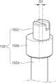
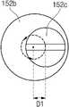
图8a及图8b是图1所示的偏心销的立体图及俯视图。8a and 8b are a perspective view and a top view of the eccentric pin shown in FIG. 1 .
图9是本发明的另一实施例的移动隔板的俯视图。Fig. 9 is a top view of a mobile partition according to another embodiment of the present invention.
具体实施方式Detailed ways
下面,参照附图详细说明本发明的优选实施例,以使本发明所属技术领域中具有通常知识的人员能够易于实施本发明。Hereinafter, preferred embodiments of the present invention will be described in detail with reference to the accompanying drawings so that those having ordinary knowledge in the technical field to which the present invention pertains can easily implement the present invention.
图1是表示本发明的一实施例的槽模的分解立体图。图2是表示本发明的一实施例的槽模的侧视图。图3是图1所示的第一模的俯视图。图4a及图4b是表示从本发明的一实施例的槽模排出的浆液在衬底上涂布的形态的俯视图及侧视图。图5是图1所示的A部分的放大图。图6a及图6b是图1所示的移动隔板的俯视图。图7a及图7b是表示移动隔板的动作的俯视图。图8a及图8b是图1所示的偏心销的立体图及俯视图。Fig. 1 is an exploded perspective view showing a slot die according to an embodiment of the present invention. Fig. 2 is a side view showing a slot die according to an embodiment of the present invention. Fig. 3 is a plan view of the first mold shown in Fig. 1 . 4a and 4b are a plan view and a side view showing how the slurry discharged from the slot die according to one embodiment of the present invention is coated on the substrate. FIG. 5 is an enlarged view of part A shown in FIG. 1 . 6a and 6b are top views of the movable partition shown in FIG. 1 . 7a and 7b are plan views showing the movement of the movable partition. 8a and 8b are a perspective view and a top view of the eccentric pin shown in FIG. 1 .
参照图1至图5,本发明的一实施例的槽模100包括第一模110、第二模120、固定隔板130、移动隔板140及调节装置150。Referring to FIGS. 1 to 5 , a
所述第一模110构成为大致六面体形状,具有平坦的上表面110a及平坦的下表面110b。所述第一模110的上表面110a构成为大致长方形,在中央形成有作为储存浆液的槽的储存部115。因此,所述第一模110的上表面110a沿所述储存部115的外周缘形成为长方形的带状,并且包括沿所述第一模110的长度方向形成且彼此相对的第一面111和第二面112以及连接所述第一面111和第二面112且彼此相对的第三面113和第四面114。The
所述第一面111为浆液排出的面,所述第二面112、第三面113及第四面114为固定隔板130结合的面。在此,在所述第一面111结合移动隔板140。在所述第一面111形成结合孔,在所述结合孔结合所述调节装置150的基准销151和偏心销152。所述结合孔可通过基准销151结合的一个孔和偏心销152结合的两个孔,共三个孔构成一组,并隔开规定的间隔而形成。在此,对于在所述第一面111的两端部形成的结合孔,以基准销151和偏心销152分别只结合一个孔的形式可形成两个孔。The
此外,在所述储存部115形成有浆液注入的注入口116。通过所述注入口116注入的浆液储存于所述储存部115,并通过所述第一面111向外部排出。In addition, an
所述第二模120与所述第一模110相对形成,并以覆盖所述储存部115的方式与所述第一模110结合。所述第二模120具有平坦的上表面120a及平坦的下表面120b,所述下表面120b与所述第一模110的上表面110a对应形成。即,所述第二模120的下表面120b和所述第一模110的上表面110a彼此相对结合。The
所述固定隔板130介于所述第一模110和所述第二模120之间。所述固定隔板130以与连接所述第一模110的第二面112、第三面113及第四面114的形状相对应的形状形成,并且在一侧形成开放部131。即,所述固定隔板130大致以“コ”形形状形成,并结合固定于所述第一模110的上表面110a。此外,所述固定隔板130的厚度与所述浆液涂布的量相关。所述固定隔板130的厚度越厚,所述第一模110和第二模120之间的间隔越宽,从而通过所述第一面111排出的浆液的量越多,所述固定隔板130的厚度越薄,所述第一模110和第二模120之间的间隔越窄,从而通过所述第一面111排出的浆液的量越少。即,所述固定隔板130确定浆液在衬底10涂布的厚度。The fixed
所述移动隔板140介于所述第一模110和所述第二模120之间。所述移动隔板140形成于所述第一模110的第一面111,位于所述固定隔板130的开放部131。所述移动隔板140可在所述第一面111隔开一定间隔形成多个。如图3所示,由所述移动隔板140的隔开间隔,确定涂布于衬底10的浆液的宽度W。此外,所述移动隔板140形成为厚度与所述固定隔板130的厚度相同,储存于所述储存部115的浆液排出至所述移动隔板140之间隔开的部分。在图中,示出所述移动隔板140形成于三处,浆液从两处排出,但所述移动隔板140可形成为与之相比更多或者更少。The moving
参照图6a及图6b,所述移动隔板140包括第一移动隔板141及第二移动隔板142。在此,所述第一移动隔板141和所述第二移动隔板142彼此分开而形成,并形成为左右对称。此外,如图7a及图7b所示,所述移动隔板140可通过使所述第一移动隔板141及所述第二移动隔板142向内侧变窄,或者向外侧变宽,调节浆液排出的宽度。Referring to FIG. 6 a and FIG. 6 b , the moving
所述第一移动隔板141包括第一基准孔141a、第一导孔141b、第一结合部141c及第一角部141d。The first
所述第一基准孔141a构成为圆形,在所述第一基准孔141a结合调节装置150的基准销151。此外,所述第一基准孔141a形成为直径与所述基准销151的直径相同,在所述第一移动隔板141向内侧或向外侧移动时,起到为中心的作用。The
所述第一导孔141b构成为椭圆形,在所述第一导孔141b结合调节装置150的偏心销152。此外,所述第一导孔141b形成为直径比所述偏心销152的直径大,从而使所述偏心销152顺利移动。The
所述第一结合部141c为形成于所述第一基准孔141a的外周缘的区域,所述第一结合部141c形成为与所述第一移动隔板141的厚度相比较薄。在此,由于所述第一结合部141c与所述第二移动隔板142的第二结合部142c结合,因此其厚度形成得较薄。The
所述第一角部141d形成于所述第一移动隔板141的外周缘。在所述第一角部141d形成倒棱,所述第一角部141d构成的角度为锐角。此外,在排出浆液时,所述第一角部防止浆液跃上所述移动隔板并移动,从而能够将浆液涂布的宽度保持恒定。特别是,如图7b所示,由于在所述第一角部141d形成有倒棱,因此在将所述移动隔板140向外侧扩宽而使浆液排出的宽度变窄时,能够防止浆液跃上移动隔板140并移动。如此,所述移动隔板140通过在所述第一角部141d形成倒棱,能够将浆液涂布的宽度保持相同。The
所述第二移动隔板142包括第二基准孔142a、第二导孔142b、第二结合部142c及第二角部142d。所述第二移动隔板142为将所述第一移动隔板141翻过来的形状,所述第二移动隔板142和第一移动隔板141左右对称。因此,省略对所述第二移动隔板142的说明。The second
所述浆液排出的宽度为相邻的移动隔板140之间的间隔。更为详细地,参照图3,所述浆液排出的宽度指的是从第一个移动隔板中第一移动隔板141的第一角部141d到第二个移动隔板中第二移动隔板142的第二角部142d之间的宽度W。因此,如图7a所示,如果所述第一移动隔板141及第二移动隔板142向内侧变窄,浆液排出的宽度变宽。此外,如图7b所示,如果所述第一移动隔板141及第二移动隔板142向外侧变宽时,浆液排出的宽度变窄。The width of the slurry discharge is the interval between adjacent moving
所述调节装置150通过形成于所述第一模110的结合孔,结合于所述移动隔板140,通过将所述移动隔板140向内侧或向外侧调节,确定浆液排出的宽度。所述调节装置150包括基准销151、偏心销152及驱动部153。The adjusting
所述基准销151贯穿所述第一模110,与所述第一移动隔板141的第一基准孔141a及所述第二移动隔板142的第二基准孔142a结合。此时,所述第一基准孔141a和第二基准孔142a相互重叠。所述基准销151固定于所述第一模110,起到所述移动隔板140能够移动的中心轴的作用。The
所述偏心销152贯穿所述第一模110,与所述第一移动隔板141的第一导孔141b及所述第二移动隔板142的第二导孔142b结合。所述偏心销152通过旋转运动,使所述移动隔板140向内侧或外侧移动。所述偏心销152可由两个构成一对,从而与第一移动隔板141及第二移动隔板142结合。而且,在所述第一模110的第一面111的两端部形成的偏心销152分别可为一个。参照图8a及图8b,所述偏心销152包括主柱152a、安放部152b及偏心部152c。The
所述主柱152a贯穿所述第一模110而形成,上部形成有安放部152b及偏心部152c,下部结合驱动部153。所述主柱152a通过结合于下部的驱动部153旋转。The
所述安放部152b形成于所述主柱152a的上部,其直径形成为比所述主柱152a的直径大。所述安放部152b为固定所述移动隔板140的部分。The
所述偏心部152c形成于所述安放部152b的上部,其直径形成为比所述安放部152b的直径小。所述偏心部152c形成为从所述安放部152b的中心偏离而偏心。因此,所述安放部152b的中心和所述偏心部152c的中心互不一致,所述偏心部152c偏心,从而产生距离差D1。在此,所述主柱152a和所述安放部152b的中心相互一致。所述偏心部152c结合于所述移动隔板140的导孔141b、142b,通过所述偏心部152c的旋转半径,所述移动隔板140向内侧或向外侧移动。在此,由于所述偏心部152c从所述主柱152a及安放部152b的中心偏心,因此即使所述偏心销152在自己的位置旋转,所述移动隔板140也能够向内侧或向外侧移动。即,根据所述偏心部152c的偏心量确定所述移动隔板140的移动范围。The
所述驱动部153结合于所述偏心销152的下部,起到使所述偏心销152旋转的作用。所述驱动部153可由适用蜗轮减速器的齿轮箱及电动机等形成,使所述偏心销152旋转。由于所述驱动部153驱动而使所述偏心销152旋转,所述移动隔板140能够向内侧或向外侧移动。The driving part 153 is combined with the lower part of the
这种调节装置150实时监视浆液在衬底上涂布的宽度,并与设定在内部的设定值比较。所述调节装置150在所述浆液的涂布宽度脱离设定值时,自动反馈调节(即,反馈控制)移动隔板140。关于所述调节装置调节移动隔板的方法简单地说明如下。The adjusting
首先,所述移动隔板140设置成与第一模110的第一面111正交。在该状态下,所述槽模100排出储存于储存部115的浆液。所述调节装置150实时监视所述浆液在衬底10上涂布的宽度。此外,所述调节装置150测量并储存所述浆液的涂布宽度,并与在内部设定的值相比较。如果所测量的浆液的涂布宽度与所设定的值之间存在差,则所述调节装置150使偏心销152旋转,从而使移动隔板140移动,使得浆液的涂布宽度与设定值相同。在此,所述偏心销152的旋转方向由所述浆液的涂布宽度的测量值和设定值的差来确定。进一步地,所述偏心销152的旋转范围由浆液的涂布速度和移动隔板140的移动精度以及测量值对比设定值的脱离程度(即,涂布宽度脱离的程度)来确定。即,当浆液的涂布速度快,或者测量值对比设定值的脱离程度大时,所述偏心销152的旋转范围变大。反之,当浆液的涂布速度慢,测量值对比设定值的脱离程度小时,所述调节装置150为了进行精细的控制,使偏心销152的旋转范围变小。进一步地,所述调节装置150可按每一规定时间,检查涂布宽度,并根据关于涂布宽度脱离的方向的次数(例如,涂布宽度脱离的相同方向的计数),调节所述偏心销152。First, the
如此,本发明的一实施例的槽模100包括介于第一模110和第二模120之间的移动隔板140,并通过调节所述移动隔板140,能够调节涂布于衬底10的浆液的涂布宽度。In this way, the slot die 100 according to an embodiment of the present invention includes a
此外,本发明的一实施例的槽模100具备从中心向一侧偏心的偏心销152,从而能够通过所述偏心销152旋转,调节移动隔板140的动作。In addition, the slot die 100 according to an embodiment of the present invention includes an
接下来,说明本发明的另一实施例的移动隔板。Next, a movable partition according to another embodiment of the present invention will be described.
图9是本发明的另一实施例的移动隔板的俯视图。图9所示的移动隔板240与图6a所示的移动隔板140相似。下面,只对其不同的部分进行说明。Fig. 9 is a top view of a mobile partition according to another embodiment of the present invention. The moving
参照图9,本发明的另一实施例的移动隔板240包括第一移动隔板241、第二移动隔板242及变形部243。在此,所述移动隔板240为在图6a所示的移动隔板140中,不具有第一结合部141c和第二结合部142c,且第一移动隔板241及第二移动隔板242为一体形成的结构。Referring to FIG. 9 , a moving
在所述第一移动隔板241及所述第二移动隔板242分别形成导孔241a、242a,调节装置150的偏心销152与其结合。此外,在所述移动隔板240的下端中心部形成基准孔240b,调节装置150的基准销151与其结合。即,所述移动隔板240在与图7a所示的移动隔板140的导孔141a、142a及基准孔141b、142b对应的部分同样地形成有导孔241a、242a及基准孔240b。但是,由于所述移动隔板240一体形成,所以基准孔240b只形成一个。此外,在所述第一移动隔板241及第二移动隔板242的外侧周缘形成有角部241d、242d,在所述角部241d、242d形成有倒棱。所述第一移动隔板241与所述第二移动隔板242左右对称。
所述变形部243是形成于所述移动隔板240的两侧(例如,形成于以下说明的孔243a的两侧),且为与所述第一移动隔板241及所述第二移动隔板242的宽度相比较窄形成的部分。此外,所述变形部243由于横向形成在所述移动隔板240的中央的孔243a,形成为其宽度比所述第一移动隔板241及所述第二移动隔板242的宽度窄。所述变形部243在所述移动隔板240向内侧或向外侧移动时,能够通过弯曲来调节浆液排出的宽度。The
以上说明的内容只是为了实施本发明的槽模的一实施例,本发明不限于前述实施例,并认为本发明的技术精神存在至如下范围:如所附权利要求书要求的那样在不脱离本发明要旨的范围内,只要是本发明所属领域的具有通常知识的人员均能进行多种变更实施的范围。The content of the above description is only to implement an embodiment of the slot die of the present invention, the present invention is not limited to the foregoing embodiments, and it is considered that the technical spirit of the present invention exists to the following scope: as required by the appended claims, without departing from the present invention Within the scope of the gist of the invention, it is within the range that a person having ordinary knowledge in the field to which the present invention pertains can make various changes and implement it.
符号说明Symbol Description
100 槽模100 slot die
110 第一模110 first mold
111 第一面111 First side
112 第二面112 Second side
113 第三面113 The third side
114 第四面114 Fourth side
115 储存部115 Storage Department
116 注入口116 injection port
120 第二模120 second mold
130 固定隔板130 fixed partition
140、240 移动隔板140, 240 Mobile Partition
141、241 第一移动隔板141, 241 The first mobile partition
141a 第一基准孔141a First datum hole
141b 第一导孔141b first guide hole
141c 第一结合部141c first junction
141d 第一角部141d First corner
142、242 第二移动隔板142, 242 Second mobile partition
142a 第二基准孔142a Second datum hole
142b 第二导孔142b Second guide hole
142c 第二结合部142c second junction
142d 第二角部142d Second corner
243 变形部243 Deformation Department
150 调节装置150 adjustment device
151 基准销151 reference pin
152 偏心销152 Eccentric pin
152a 主柱152a main column
152b 安放部152b Placement Department
152c 偏心部152c Eccentric part
153 驱动部153 drive unit
Claims (18)
Translated fromChineseApplications Claiming Priority (2)
| Application Number | Priority Date | Filing Date | Title |
|---|---|---|---|
| KR1020120020536AKR101897827B1 (en) | 2012-02-28 | 2012-02-28 | Slot die for controlling slurry coating width |
| KR10-2012-0020536 | 2012-02-28 |
Publications (2)
| Publication Number | Publication Date |
|---|---|
| CN103286040Atrue CN103286040A (en) | 2013-09-11 |
| CN103286040B CN103286040B (en) | 2017-06-13 |
Family
ID=49087873
Family Applications (1)
| Application Number | Title | Priority Date | Filing Date |
|---|---|---|---|
| CN201210261782.5AActiveCN103286040B (en) | 2012-02-28 | 2012-07-26 | The channel mould of adjustable coating width |
Country Status (3)
| Country | Link |
|---|---|
| JP (1) | JP6057539B2 (en) |
| KR (1) | KR101897827B1 (en) |
| CN (1) | CN103286040B (en) |
Cited By (4)
| Publication number | Priority date | Publication date | Assignee | Title |
|---|---|---|---|---|
| CN104174565A (en)* | 2014-08-20 | 2014-12-03 | 东莞新能源科技有限公司 | Coating device |
| CN104998800A (en)* | 2015-08-07 | 2015-10-28 | 泉州新日成热熔胶设备有限公司 | High-accuracy measuring and coating die |
| CN105080741A (en)* | 2015-06-10 | 2015-11-25 | 深圳市华星光电技术有限公司 | Coating spray head, coating device with same and coating method of coating device |
| CN115335157A (en)* | 2020-07-14 | 2022-11-11 | 株式会社Lg新能源 | Mold coating machine and its inspection device |
Families Citing this family (14)
| Publication number | Priority date | Publication date | Assignee | Title |
|---|---|---|---|---|
| KR101631528B1 (en)* | 2014-09-26 | 2016-06-17 | 주식회사 케이티앤지 | APPARATUS Of CUTTING CIGARETTE PACKING PAPER |
| JP6927845B2 (en)* | 2017-10-20 | 2021-09-01 | 株式会社ヒラノテクシード | Coating equipment |
| KR102292321B1 (en)* | 2017-10-31 | 2021-08-20 | 주식회사 엘지에너지솔루션 | Manufacturing method of electrode for secondary battery |
| JP6904583B2 (en)* | 2018-12-18 | 2021-07-21 | 株式会社飯沼ゲージ製作所 | Slit coater |
| CN110302942B (en)* | 2019-07-17 | 2024-05-24 | 宁波维科电池有限公司 | Coating die head for single or multiple groups of lithium battery pole pieces |
| KR102866099B1 (en)* | 2019-11-20 | 2025-09-26 | 삼성에스디아이 주식회사 | Rechargeable battery electrode manufacturing slot die |
| KR20210083512A (en) | 2019-12-27 | 2021-07-07 | 주식회사 엘지에너지솔루션 | Electrode slurry coating shim with excellent coating uniformity and coating die comprising the same |
| KR20230052058A (en)* | 2021-10-12 | 2023-04-19 | 주식회사 엘지에너지솔루션 | Coating die for lithium secondary battery including removable spacer shims |
| KR102559843B1 (en) | 2021-11-10 | 2023-07-27 | 건국대학교 산학협력단 | Performance control method and device of large-area transparent water repellent film according to process parameters based on roll-to-roll continuous process |
| WO2023135218A1 (en)* | 2022-01-14 | 2023-07-20 | Advent Technologies Gmbh | Method and device for providing uniform carbon-comprising catalytic ink coatings for electrodes and related method |
| KR102858473B1 (en)* | 2022-06-08 | 2025-09-10 | 주식회사 엘지에너지솔루션 | Offset adjustment device and coating device including the same |
| KR20240024528A (en)* | 2022-08-17 | 2024-02-26 | 주식회사 엘지에너지솔루션 | Slot die coater capable of automatically adjusting position of the shim plate and method of adjusting position of shim plate of slot die coater |
| KR20250123430A (en)* | 2024-02-08 | 2025-08-18 | 주식회사 엘지에너지솔루션 | A potision control devide of shim for slot die coater and a position control method of shim for slot die coater using the same |
| KR102726009B1 (en) | 2024-06-13 | 2024-11-05 | 주식회사 디씨에스 | slot die |
Citations (5)
| Publication number | Priority date | Publication date | Assignee | Title |
|---|---|---|---|---|
| JPH09131560A (en)* | 1995-11-09 | 1997-05-20 | Toray Ind Inc | Coating device and coating method as well as apparatus for production of color filter and its production |
| US6423144B1 (en)* | 1996-08-07 | 2002-07-23 | Matsushita Electric Industrial Co., Ltd. | Coating apparatus and coating method |
| JP2006122884A (en)* | 2004-09-30 | 2006-05-18 | Dainippon Printing Co Ltd | Coating apparatus and coating method |
| CN101279310A (en)* | 2007-04-03 | 2008-10-08 | 中外炉工业株式会社 | Substrate coating apparatus and coating method thereof |
| CN102259076A (en)* | 2010-05-24 | 2011-11-30 | 三星Sdi株式会社 | Active material coating apparatus and coating method using the same |
Family Cites Families (6)
| Publication number | Priority date | Publication date | Assignee | Title |
|---|---|---|---|---|
| JP3021838B2 (en)* | 1991-09-24 | 2000-03-15 | 三菱化学株式会社 | Coating head |
| JP3039243B2 (en)* | 1993-12-22 | 2000-05-08 | 三菱化学株式会社 | Application method |
| JP2524484B2 (en)* | 1994-07-28 | 1996-08-14 | 中外炉工業株式会社 | Coating width adjustment die coater |
| JPH10137655A (en)* | 1996-11-12 | 1998-05-26 | Toshiba Corp | Liquid coating device |
| JPH11179260A (en)* | 1997-12-19 | 1999-07-06 | Fuji Photo Film Co Ltd | Coating width changing device |
| JP2006255643A (en)* | 2005-03-18 | 2006-09-28 | Hitachi Chem Co Ltd | Coating machine and coating method using it |
- 2012
- 2012-02-28KRKR1020120020536Apatent/KR101897827B1/enactiveActive
- 2012-05-07JPJP2012105973Apatent/JP6057539B2/enactiveActive
- 2012-07-26CNCN201210261782.5Apatent/CN103286040B/enactiveActive
Patent Citations (5)
| Publication number | Priority date | Publication date | Assignee | Title |
|---|---|---|---|---|
| JPH09131560A (en)* | 1995-11-09 | 1997-05-20 | Toray Ind Inc | Coating device and coating method as well as apparatus for production of color filter and its production |
| US6423144B1 (en)* | 1996-08-07 | 2002-07-23 | Matsushita Electric Industrial Co., Ltd. | Coating apparatus and coating method |
| JP2006122884A (en)* | 2004-09-30 | 2006-05-18 | Dainippon Printing Co Ltd | Coating apparatus and coating method |
| CN101279310A (en)* | 2007-04-03 | 2008-10-08 | 中外炉工业株式会社 | Substrate coating apparatus and coating method thereof |
| CN102259076A (en)* | 2010-05-24 | 2011-11-30 | 三星Sdi株式会社 | Active material coating apparatus and coating method using the same |
Cited By (5)
| Publication number | Priority date | Publication date | Assignee | Title |
|---|---|---|---|---|
| CN104174565A (en)* | 2014-08-20 | 2014-12-03 | 东莞新能源科技有限公司 | Coating device |
| CN104174565B (en)* | 2014-08-20 | 2016-02-10 | 东莞新能源科技有限公司 | Apparatus for coating |
| CN105080741A (en)* | 2015-06-10 | 2015-11-25 | 深圳市华星光电技术有限公司 | Coating spray head, coating device with same and coating method of coating device |
| CN104998800A (en)* | 2015-08-07 | 2015-10-28 | 泉州新日成热熔胶设备有限公司 | High-accuracy measuring and coating die |
| CN115335157A (en)* | 2020-07-14 | 2022-11-11 | 株式会社Lg新能源 | Mold coating machine and its inspection device |
Also Published As
| Publication number | Publication date |
|---|---|
| KR20130098758A (en) | 2013-09-05 |
| JP2013176748A (en) | 2013-09-09 |
| KR101897827B1 (en) | 2018-09-12 |
| CN103286040B (en) | 2017-06-13 |
| JP6057539B2 (en) | 2017-01-11 |
Similar Documents
| Publication | Publication Date | Title |
|---|---|---|
| CN103286040B (en) | The channel mould of adjustable coating width | |
| JP6857565B2 (en) | Display device | |
| JP5542523B2 (en) | Slit die | |
| US8419094B2 (en) | Non-contact transport apparatus | |
| CN103984181B (en) | Liquid crystal lens and display device | |
| US20140290786A1 (en) | Microfluidic channel and microfluidic device | |
| CN107665633A (en) | Display device | |
| JP6552643B2 (en) | Foldable container | |
| CN108004503A (en) | Mask plate, evaporated device and device | |
| WO2017045392A1 (en) | Display substrate and wearable device | |
| CN104152845B (en) | Mask assembly and the membrane deposition method using mask assembly | |
| WO2019085700A1 (en) | Array substrate and manufacturing method therefor, and display device and manufacturing method therefor | |
| CN107390443A (en) | Display panel and display device | |
| KR102056479B1 (en) | Slot-die performing multi-coating | |
| JP2013195856A5 (en) | ||
| WO2016031499A1 (en) | Device for manufacturing electrode plate for cell | |
| TWI640823B (en) | Pixel structure and display panel | |
| JPS6124718B2 (en) | ||
| JP2007192917A5 (en) | ||
| JP2020022928A (en) | Coating tool | |
| US9625768B2 (en) | Pixel structure, display panel and display device | |
| KR101308251B1 (en) | Slot Die | |
| JP2006015722A5 (en) | ||
| WO2020045308A1 (en) | Coating device and coating method | |
| CN207366902U (en) | Display panel and display device |
Legal Events
| Date | Code | Title | Description |
|---|---|---|---|
| C06 | Publication | ||
| PB01 | Publication | ||
| C10 | Entry into substantive examination | ||
| SE01 | Entry into force of request for substantive examination | ||
| GR01 | Patent grant | ||
| GR01 | Patent grant |