CN103270737A - Mobile terminal device and mobile terminal device control method - Google Patents
Mobile terminal device and mobile terminal device control methodDownload PDFInfo
- Publication number
- CN103270737A CN103270737ACN2010800709376ACN201080070937ACN103270737ACN 103270737 ACN103270737 ACN 103270737ACN 2010800709376 ACN2010800709376 ACN 2010800709376ACN 201080070937 ACN201080070937 ACN 201080070937ACN 103270737 ACN103270737 ACN 103270737A
- Authority
- CN
- China
- Prior art keywords
- mobile terminal
- vibration
- spectrum
- vibrator
- frequency
- Prior art date
- Legal status (The legal status is an assumption and is not a legal conclusion. Google has not performed a legal analysis and makes no representation as to the accuracy of the status listed.)
- Granted
Links
Images


Classifications
- H—ELECTRICITY
- H04—ELECTRIC COMMUNICATION TECHNIQUE
- H04M—TELEPHONIC COMMUNICATION
- H04M19/00—Current supply arrangements for telephone systems
- H04M19/02—Current supply arrangements for telephone systems providing ringing current or supervisory tones, e.g. dialling tone or busy tone
- H04M19/04—Current supply arrangements for telephone systems providing ringing current or supervisory tones, e.g. dialling tone or busy tone the ringing-current being generated at the substations
- H04M19/047—Vibrating means for incoming calls
- H—ELECTRICITY
- H04—ELECTRIC COMMUNICATION TECHNIQUE
- H04M—TELEPHONIC COMMUNICATION
- H04M1/00—Substation equipment, e.g. for use by subscribers
- H04M1/02—Constructional features of telephone sets
- H04M1/0202—Portable telephone sets, e.g. cordless phones, mobile phones or bar type handsets
- H04M1/0206—Portable telephones comprising a plurality of mechanically joined movable body parts, e.g. hinged housings
- H04M1/0241—Portable telephones comprising a plurality of mechanically joined movable body parts, e.g. hinged housings using relative motion of the body parts to change the operational status of the telephone set, e.g. switching on/off, answering incoming call
Landscapes
- Engineering & Computer Science (AREA)
- Signal Processing (AREA)
- Telephone Function (AREA)
Abstract
Translated fromChinese
Description
Translated fromChinese技术领域technical field
本发明涉及具有振动器功能的移动终端装置以及移动终端装置控制方法。The present invention relates to a mobile terminal device having a vibrator function and a control method of the mobile terminal device.
背景技术Background technique
以往,存在当来信时使振动器振动来对用户通知来信的移动终端装置。但是,根据移动终端装置被放置的场所不同,有时会因振动器的响动而产生令人不快的声音。Conventionally, there are mobile terminal devices that vibrate a vibrator to notify a user of an incoming call when a call arrives. However, depending on the place where the mobile terminal device is placed, unpleasant sounds may be generated by the vibration of the vibrator.
鉴于此,有一种利用扩音器来测定振动器响动时和停止时的周围的声压级,并将声压级之差与阈值进行比较来控制振动器的响动的技术。In view of this, there is a technique of using a microphone to measure the surrounding sound pressure levels when the vibrator is running and when it is stopped, and comparing the difference between the sound pressure levels with a threshold to control the sound of the vibrator.
另外,还有一种判别噪声的原因是否因振动器引起,并基于该判别结果来控制振动器的振动强度的技术。In addition, there is another technique of judging whether or not the cause of the noise is caused by the vibrator, and controlling the vibration intensity of the vibrator based on the judging result.
专利文献1:日本特开2004-56623号公报Patent Document 1: Japanese Patent Laid-Open No. 2004-56623
专利文献2:日本特开2004-129120号公报Patent Document 2: Japanese Patent Laid-Open No. 2004-129120
对移动终端装置而言,在被放入到包中或者西服口袋的情况下,经常不会发觉振动器的振动。例如,难以发觉振动器振动的包中或西服口袋以多个面与移动终端装置接触,而容易发觉振动器振动的桌子上等则以一个面与移动终端装置接触。When a mobile terminal device is put into a bag or a pocket of a suit, the vibration of the vibrator is often not felt. For example, the mobile terminal device is in contact with multiple surfaces in a bag or a suit pocket where the vibration of the vibrator is difficult to detect, and the mobile terminal device is in contact with one surface on a table where the vibration of the vibrator is easily detected.
可认为如果推断出移动终端装置的接触状态,则能够恰当地控制移动终端装置在来信时的动作。另一方面,在现有技术中,由于只能将周围声音的功率作为判断材料,所以即使接触状态变化,声音的功率也几乎不变而无法推断接触状态。It is considered that if the contact state of the mobile terminal device is inferred, it is possible to appropriately control the operation of the mobile terminal device when a call is received. On the other hand, in the prior art, only the power of the surrounding sound can be used as a judgment material, so even if the contact state changes, the sound power hardly changes and the contact state cannot be inferred.
发明内容Contents of the invention
鉴于此,公开的技术的目的在于,提供一种在具有振动器功能的移动终端装置中能够推断移动终端装置的接触状态,来进行适当的来信控制的移动终端装置以及移动终端装置控制方法。In view of this, an object of the disclosed technology is to provide a mobile terminal device and a mobile terminal device control method capable of inferring the contact state of the mobile terminal device and performing appropriate call control in a mobile terminal device having a vibrator function.
公开的一个方式的移动终端装置具备:使壳体振动的振动器、针对来自扩音器的输入音进行频率分析的分析部、计算出由上述分析部针对上述壳体振动时的输入音所求出的频谱的时间性变化量的计算部、以及基于由上述计算部计算出的时间性变化量来进行来信控制的控制部。A mobile terminal device disclosed in one aspect includes: a vibrator for vibrating a housing, an analysis unit for analyzing the frequency of an input sound from a microphone, and a calculation unit that calculates the frequency of the input sound when the housing vibrates. A calculation unit for calculating the amount of temporal change of the obtained frequency spectrum, and a control unit for performing incoming call control based on the amount of temporal change calculated by the calculation unit.
根据公开的技术,能够在具有振动器功能的移动终端装置中推断移动终端装置的接触状态,进行适当的来信控制。According to the disclosed technology, in a mobile terminal device having a vibrator function, it is possible to estimate the contact state of the mobile terminal device and perform appropriate incoming call control.
附图说明Description of drawings
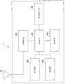
图1是表示实施例1中的移动终端装置的硬件的一个例子的框图。FIG. 1 is a block diagram showing an example of hardware of a mobile terminal device in the first embodiment.
图2是表示实施例1中的控制部的功能的一个例子的框图。FIG. 2 is a block diagram showing an example of functions of a control unit in the first embodiment.
图3是表示频谱的时间变化的图。FIG. 3 is a diagram showing time changes of frequency spectrum.
图4是用于对杂音的影响进行说明的图。FIG. 4 is a diagram for explaining the influence of noise.
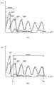
图5是表示频谱的时间变化的一个例子的图。FIG. 5 is a diagram showing an example of a temporal change of a frequency spectrum.
图6是表示来信控制部中的来信控制的功能的一个例子的框图。FIG. 6 is a block diagram showing an example of functions of incoming call control in the incoming call control unit.
图7是表示振动器的振动调节结果的例子的图。FIG. 7 is a diagram showing an example of a vibration adjustment result of a vibrator.
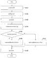
图8是表示实施例1中的移动终端装置的控制处理的一个例子的流程图。8 is a flowchart showing an example of control processing of the mobile terminal device in the first embodiment.
图9是表示实施例2中的控制部的功能的一个例子的框图。FIG. 9 is a block diagram showing an example of functions of a control unit in the second embodiment.
图10是表示实施例2中的移动终端装置的控制处理的一个例子的流程图。10 is a flowchart showing an example of control processing of the mobile terminal device in the second embodiment.
图11是表示实施例3中的控制部的功能的一个例子的框图。FIG. 11 is a block diagram showing an example of the functions of the control unit in the third embodiment.
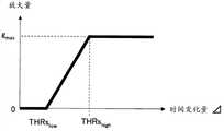
图12是表示呼叫音的放大量与时间变化量之间的关系的一个例子的图。FIG. 12 is a diagram showing an example of the relationship between the amount of amplification of the paging sound and the amount of time change.
图13是表示实施例3中的移动终端装置的控制处理的一个例子的流程图。FIG. 13 is a flowchart showing an example of control processing of the mobile terminal device in the third embodiment.
附图标记说明Explanation of reference signs
30、31、32-控制部;40-振动器;50-扩音器;60-扬声器;101-频率分析部;102-频谱变动计算部;103-杂音推断部;104、204、301-来信控制部;141-振动器控制部;142-呼叫音控制部;201-光传感器;202-存储器;203-受光变动输出部。30, 31, 32 - control department; 40 - vibrator; 50 - loudspeaker; 60 - loudspeaker; 101 - frequency analysis department; 102 - spectrum change calculation department; 103 - noise estimation department; 104, 204, 301 - letter Control part; 141-vibrator control part; 142-call sound control part; 201-light sensor; 202-memory; 203-light receiving change output part.
具体实施方式Detailed ways
以下,基于附图对实施例进行说明。Hereinafter, an embodiment will be described based on the drawings.
[实施例1][Example 1]
<构成><Composition>
图1是表示实施例1中的移动终端装置1的硬件的一个例子的框图。移动终端装置1具有天线10、无线电部20、控制部30、振动器40、扩音器50、扬声器60、以及终端接口部70。FIG. 1 is a block diagram showing an example of hardware of a mobile terminal device 1 in the first embodiment. The mobile terminal device 1 has an
天线10对被发送放大器放大后的无线信号进行发送,而且,从基站接收无线信号。无线电部20对被控制部30扩散后的发送信号进行D/A变换,通过正交调制变换成高频信号,并利用电力放大器对该信号进行放大。无线电部20将接收到的无线信号放大,并对该信号进行A/D变换并传输至控制部30。The
控制部30进行发送数据的错误修正符的追加、数据调制、扩散调制、接收信号的逆扩散、接收环境的判断、各信道信号的阈值判断、错误修正解码等基带处理等。另外,控制部30还进行控制信号的收发等无线控制。此外,基带处理也可以由与控制部30不同的构成进行。The
终端接口部70进行数据用适配器处理、电话听筒与外部数据终端的接口处理。The
<功能><Function>
接下来,对实施例1中的移动终端装置1的功能进行说明。图2是表示实施例1中的控制部30的功能的一个例子的框图。如图2所示,控制部30包括:频率分析部101、频谱变动计算部102、杂音推断部103、来信控制部104。Next, the functions of the mobile terminal device 1 in the first embodiment will be described. FIG. 2 is a block diagram showing an example of functions of the
频率分析部101从扩音器50取得输入音,针对取得的输入音进行频率分析。输入音包括振动音、背景音等。频率分析例如只要使用高速傅立叶变换(FFT)、小波变换等已知的技术进行即可。The
频率分析部101例如对输入音(8kHz)进行FFT(256点)。输入音用x(n)表示,输入频谱用X(f)表示。另外,频率分析部101根据输入频谱利用以下的式(1)来计算能谱。The
[数1][number 1]
S(f)=10log10(|X(f)2|)…式(1)S(f)=10log10 (|X(f)2 |)…Formula (1)
S(f)表示能谱。S(f) represents the energy spectrum.
由频率分析部101求出的能谱S(f)被向频谱变动计算部102、杂音推断部103输出。The power spectrum S(f) obtained by the
频谱变动计算部102根据从频率分析部101取得的能谱,计算出时间性的能谱的变化量。以下分成除去杂音影响的情况和不除去杂音影响的情况来说明该变化量的计算方式。The spectrum
(1)不除去杂音影响的情况(1) When the influence of noise is not removed
频谱变动计算部102利用以下的式(2)来计算能谱的时间性变化量(以下也称为时间变化量)。The spectrum
[数2][number 2]
Δ:时间变化量的平均Δ: Average of time variation
t:帧编号t: frame number
f:频率编号f: frequency number
St(f):t帧的能谱St (f): energy spectrum of frame t
St-1(f):t-1帧的能谱St-1 (f): energy spectrum of frame t-1
flow:所计算的频率的下限flow : the lower limit of the calculated frequency
fhigh:所计算的频率的上限fhigh : the upper limit of the calculated frequency
count:所测定的频带的数量count: the number of frequency bands measured
例如,设flow=0,fhigh=64(2kHz)。频谱变动计算部102将计算出的时间变化量Δ输出至来信控制部104。此外,关于时间变化量Δ,不必一定取平均,也可以是能谱的时间性差值的累积。For example, let flow =0, fhigh =64 (2kHz). The spectrum
图3是表示频谱的时间变化的图。图3所示的实线表示某一时刻的能谱St(f),虚线表示某一时刻-1的能谱St-1(f)。通过取得这些能谱的差值,频谱变动计算部102计算出频谱的时间变化量。FIG. 3 is a diagram showing time changes of frequency spectrum. The solid line shown in FIG. 3 represents the energy spectrum St (f) at a certain time, and the dotted line represents the energy spectrum St−1 (f) at a certain time −1. By obtaining the difference between these energy spectra, the spectrum
(2)除去杂音影响的情况(2) When removing the influence of noise
频谱变动计算部102从杂音推断部103取得杂音频谱。杂音频谱如下所述由杂音推断部103求出。The spectrum
杂音推断部103从频率分析部101取得能谱S(f)。杂音推断部103根据振动器40在停止时的能谱S(f),使用以下的式(3)求出杂音(噪声)的能谱noise(f)。移动终端装置1由于通过自身来控制振动器40,所以容易知晓振动器40的停止时。The
[数3][number 3]
noiset(f)=a·noiset-1(f)+b·S(f)…式(3)noiset (f)=a·noiset-1 (f)+b·S(f)...Formula (3)
noise(f):杂音的能谱noise(f): the energy spectrum of the noise
a、b:系数a+b=1,a、b>0a, b: coefficient a+b=1, a, b>0
杂音推断部103将使用规定时间的能谱推断出的杂音能谱输出至频谱变动计算部102。The
频谱变动计算部102在利用从杂音推断部103取得的杂音能谱将杂音除去后的规定频带中,计算出能谱的时间变化量。The spectrum
图4是用于对杂音的影响进行说明的图。图4(A)针对在所有频带中计算时间变化量的情况进行说明。图4(A)所示的Sp1表示某一时刻m的杂音的能谱,Sp2表示时刻m-1的杂音能谱,Sp3表示时刻m的振动音的能谱,Sp4表示时刻m-1的振动音的能谱。在图4(A)所示的频带band1中,由于杂音的功率大,所以无法测定正确的振动音的频谱中的时间变化。FIG. 4 is a diagram for explaining the influence of noise. FIG. 4(A) explains the case of calculating the amount of time change in all frequency bands. Sp1 shown in Figure 4(A) represents the energy spectrum of the noise at a certain time m, Sp2 represents the energy spectrum of the noise at time m-1, Sp3 represents the energy spectrum of the vibration sound at time m, and Sp4 represents the vibration at time m-1 sound energy spectrum. In the frequency band band1 shown in FIG. 4(A) , since the power of the noise is large, it is impossible to accurately measure the temporal change in the frequency spectrum of the vibration sound.
图4(B)针对将频谱的计算范围缩小到规定频带的情况进行说明。图4(B)在杂音的影响小的频带band2中,计算频谱的时间变化量。由此,能够仅对振动音进行分析,可提高时间变化量的计算精度。其中,作为将杂音除去的规定频带的求取方法,例如可考虑以下的两种方法。FIG. 4(B) explains the case where the spectrum calculation range is narrowed down to a predetermined frequency band. FIG. 4(B) calculates the temporal variation of the frequency spectrum in the frequency band band2 where the influence of noise is small. Thereby, only the vibration sound can be analyzed, and the calculation accuracy of the amount of time change can be improved. Here, as a method of obtaining a predetermined frequency band from which noise is removed, for example, the following two methods can be considered.
·规定频带(之1)· Specified frequency band (1 of)
频谱变动计算部102将杂音能谱小于杂音的阈值的频带设为规定频带。使用该规定频带,频谱变动计算部102通过以下的式(4)来计算频谱的时间变化量。The spectrum
[数4][number 4]
noiset(f):t帧的杂音能谱noiset (f): Noise energy spectrum of frame t
THRpow:杂音的阈值THRpow : Threshold of noise
杂音的阈值THRpow为大于振动音的值,通过预先进行实验等而设定适当的值。The threshold value THRpow of the noise is a value larger than the vibration sound, and an appropriate value is set by performing experiments in advance.
·规定频带(之2)· Specified frequency band (Part 2)
频谱变动计算部102将杂音能谱与振动音的能谱之间的等级差为等级的阈值以上的频带设为规定频带。使用该规定频带,频谱变动计算部102通过以下的式(6)来计算频谱的时间变化量。The frequency spectrum
SNRf=St(f)-noiset(f)···式(5)SNRf = St (f) - noiset (f)...Formula (5)
[数5][number 5]
THRSNR:等级(SNR)的阈值THRSNR : Threshold for grade (SNR)
SNR的阈值THRSNR例如为6dB(分贝),通过预先进行实验等而设定适当的值。The threshold THRSNR of SNR is, for example, 6 dB (decibel), and an appropriate value is set by performing experiments in advance.
上述的2个规定频带可使用其中任意一个。可以预先对频谱变动计算部102设定使用其中哪一个,也可以按照适当选择的方式对频谱变动计算部102进行设定。频谱变动计算部102在除去了杂音的影响后的规定频带中,求出频谱的时间变化量,将求出的时间变化量输出至来信控制部104。Any one of the above two prescribed frequency bands can be used. Which one of them to use may be set in advance in the spectrum
另外,在计算频谱的时间变化量的情况下,频谱变动计算部102也可以只使用振动器40的振动数以及其振动数的谐波的频带。这在除去杂音的情况和不除去杂音的情况下都可应用。频谱变动计算部102例如在式(4)或者式(6)的频率f为振动器的振动数或者其振动数的谐波时,计算出频谱的时间变化量。In addition, when calculating the amount of time change in the frequency spectrum, the frequency spectrum
由此,能够使用最小限度的频率来计算出频谱的时间变化量。该情况下,频谱变动计算部102预先从来信控制部104取得振动器40的振动马达的转数。Thereby, it is possible to calculate the temporal change amount of the spectrum using the minimum frequency. In this case, the spectrum
来信控制部104根据从频谱变动计算部102取得的频谱的时间变化量Δ来推断移动终端装置1的接触状态。在此,在移动终端装置1与桌子上等的一个面接触的情况下,时间变化量Δ小。另外,在移动终端装置2与包中或西服口袋中等的多个面接触的情况下,时间变化量Δ大。The incoming
图5是表示频谱的时间变化的一个例子的图。图5(A)表示接触状态不变化的情况的频谱的时间变化。接触状态不变化的情况例如是移动终端装置1被放置到桌子上等的一个面上的情况。图5(A)表示将移动终端装置1放置到桌子上的情况的振动音的频谱。FIG. 5 is a diagram showing an example of a temporal change of a frequency spectrum. FIG. 5(A) shows the temporal change of the frequency spectrum in the case where the contact state does not change. The case where the contact state does not change is, for example, the case where the mobile terminal device 1 is placed on one surface such as a table. FIG. 5(A) shows the frequency spectrum of the vibration sound when the mobile terminal device 1 is placed on the table.
图5(A)所示的Sp5表示时刻s的能谱,Sp6表示时刻s-1的能谱,Sp7表示时刻s-2的能谱。如图5(A)所示可知,如果接触状态不变化,则振动音的频谱的时间变化小。如果接触状态不变化,则用户容易觉察振动音。Sp5 shown in FIG. 5(A) shows the energy spectrum at time s, Sp6 shows the energy spectrum at time s-1, and Sp7 shows the energy spectrum at time s-2. As shown in FIG. 5(A) , it can be seen that if the contact state does not change, the temporal change of the frequency spectrum of the vibration sound is small. If the contact state does not change, the user can easily perceive the vibration sound.
图5(B)表示接触状态发生变化的情况的频谱的时间变化。接触状态发生变化的情况例如是移动终端装置1与包中或西服口袋中等的多个面接触的情况。图5(B)表示将移动终端装置1放入到包中的情况的振动音的频谱。FIG. 5(B) shows the temporal change of the frequency spectrum when the contact state changes. The case where the contact state changes is, for example, the case where the mobile terminal device 1 is in contact with multiple surfaces in a bag or a pocket of a suit. FIG. 5(B) shows the frequency spectrum of the vibration sound when the mobile terminal device 1 is put in a bag.
图5(A)所示的Sp8表示时刻s的能谱,Sp9表示时刻s-1的能谱,Sp10表示时刻s-2的能谱。如图5(B)所示可知,如果接触状态发生变化,则振动音的频谱的时间变化变大。如果接触状态发生变化,则用户难以觉察振动音。Sp8 shown in FIG. 5(A) represents the energy spectrum at time s, Sp9 represents the energy spectrum at time s−1, and Sp10 represents the energy spectrum at time s−2. As shown in FIG. 5(B) , it can be seen that when the contact state changes, the temporal change of the frequency spectrum of the vibration sound increases. If the contact state changes, it is difficult for the user to perceive the vibration sound.
由此,移动终端装置1可以基于振动音的频谱的时间变化量来推断移动终端装置1的壳体的接触状态。通过推断该接触状态,能够进行适当的来信控制。Thus, the mobile terminal device 1 can estimate the contact state of the case of the mobile terminal device 1 based on the amount of time change in the frequency spectrum of the vibration sound. Appropriate incoming call control can be performed by estimating the contact state.
若接收到来信信号,则来信控制部104进行振动器40以及/或者呼叫音的控制。来信控制部104根据移动终端装置1的接触状态来适当地控制振动器40以及/或者呼叫音。Upon receiving an incoming call signal, the incoming
图6是表示来信控制部104中的来信控制的功能的一个例子的框图。如图6所示,来信控制部104包括振动器控制部141、呼叫音控制部142。FIG. 6 is a block diagram showing an example of functions of incoming call control in the incoming
振动器控制部141控制振动器40的马达(未图示)。如果推断为接触状态发生变化,则振动器控制部141进行控制,以使振动器40的振动数变大。如果推断为接触状态没有变化,则振动器控制部141进行控制,以成为规定的振动数。规定的振动数是通常的振动数等。The vibrator control unit 141 controls a motor (not shown) of the
由于在来自扩音器50的输入音存在杂音的情况下容易分析振动音,所以振动器控制部141也可以调节振动器40的振动。振动器控制部141例如增大振动器40的振动,或者使振动音的频率变化。以下,针对这些方法进行说明。Since it is easy to analyze the vibration sound when the input sound from the
?控制振动数(振幅)?Control the number of vibrations (amplitude)
振动器控制部141利用以下的式(7)来累积由频谱变动计算部102取得的振动时的输入音的能谱与杂音的能谱的等级差(SNR)。The vibrator control unit 141 accumulates the level difference (SNR) between the power spectrum of the input sound and the power spectrum of the noise acquired by the spectrum
[数6][number 6]
振动器控制部141进行具有半径R不同的多个砝码的振动马达的控制。例如,在通过式(7)求出的SNR比SNR的阈值THRSNR2小的情况下,为了增大振动器40的振动或者振幅,振动器控制部141切换为半径R大的砝码。The vibrator control unit 141 controls a vibrating motor having a plurality of weights having different radii R. For example, when the SNR obtained by Equation (7) is smaller than the SNR threshold THRSNR2 , the vibrator control unit 141 switches to a weight with a larger radius R in order to increase the vibration or amplitude of the
另外,在通过式(7)求出的SNR为阈值THRSNR2以上的情况下,振动器控制部141按照使用通常的砝码的方式来进行振动器40的控制。阈值THRSNR2例如为3dB等,只要通过实验等设定适当的值即可。In addition, when the SNR obtained by Equation (7) is equal to or greater than the threshold value THRSNR2 , the vibrator control unit 141 controls the
由此,能够在杂音的影响大的情况下,增大振动器40的振动(增大振幅),使振动音中的频谱的时间变化的计算精度提高。Thereby, when the influence of the noise is large, the vibration of the
·控制频率·Control frequency
振动器控制部141取得由频谱变动计算部102取得的振动时的输入音的能谱与杂音的能谱的等级差(SNRp)(可通过式(5)计算)。The vibrator control unit 141 obtains the level difference (SNRp) between the power spectrum of the input sound and the power spectrum of the noise during vibration obtained by the spectrum variation calculation unit 102 (calculated by Equation (5)).
振动器控制部141对取得的等级差SNRp比阈值THRSNR3小的情况进行计数。由此,能够计数等级差小的频带的数量。在该计数值为阈值THRcount以上的情况下,振动器控制部141进行控制,以使振动马达的转数增加或者减少。由此,能够错移振动音的频谱的峰值出现的频率。The vibrator control unit 141 counts the cases where the acquired level difference SNRp is smaller than the threshold value THRSNR3 . Thereby, the number of frequency bands with small level differences can be counted. When the count value is equal to or greater than the threshold value THRcount , the vibrator control unit 141 controls to increase or decrease the rotation speed of the vibration motor. Thereby, the frequency at which the peak of the frequency spectrum of the vibration sound appears can be shifted.
图7是表示振动器40的振动调节结果的例子的图。图7(A)表示将振幅放大后的频谱的例子。图7(A)所示的Sp11表示杂音频谱,Sp12表示调节前的振动音的频谱,Sp13表示调节后的振动音的频谱。如图7(A)所示那样,如果使用半径R大的砝码使其振动,则振动音的振幅变大。FIG. 7 is a diagram showing an example of a vibration adjustment result of the
图7(B)表示将频率错移后的频谱的例子。图7(B)所示的Sp21表示杂音频谱,Sp22表示调节前的振动音的频谱,Sp23表示调节后的振动音的频谱。如图7(B)所示那样,通过使振动马达的转数增加,振动音的频谱向高频错移。此外,也可以通过使振动马达的转数减少,来将振动音的频谱向低频错移。FIG. 7(B) shows an example of a frequency spectrum after frequency shifting. Sp21 shown in FIG. 7(B) represents a noise spectrum, Sp22 represents a spectrum of a vibration sound before adjustment, and Sp23 represents a spectrum of a vibration sound after adjustment. As shown in FIG. 7(B) , by increasing the number of revolutions of the vibration motor, the frequency spectrum of the vibration sound is shifted to high frequencies. In addition, it is also possible to shift the frequency spectrum of the vibration sound to a low frequency by reducing the number of revolutions of the vibration motor.
通过调节图7所示那样的振动器40的振动,能够提高振动音中的频谱的时间变化的计算精度。By adjusting the vibration of the
返回到图6,在推断为接触状态发生变化的情况下,呼叫音控制部142按照增大呼叫音(来信音)的方式进行控制。在推断为接触状态没有发生变化的情况下,呼叫控制部142进行控制,以便从扬声器60输出所设定的呼叫音。Returning to FIG. 6 , when it is estimated that the contact state has changed, the paging sound control unit 142 controls to increase the paging sound (incoming sound). When it is estimated that the contact state has not changed, the call control unit 142 controls so that the set call sound is output from the
由此,移动终端装置1能够推断接触状态,并基于推断出的接触状态来适当地控制振动器40、呼叫音。Thereby, the mobile terminal device 1 can estimate the contact state, and can appropriately control the
<动作><action>
接下来,对实施例1中的移动终端装置1的动作进行说明。图8是表示实施例1中的移动终端装置1的控制处理的一个例子的流程图。Next, the operation of the mobile terminal device 1 in the first embodiment will be described. FIG. 8 is a flowchart showing an example of control processing of the mobile terminal device 1 in the first embodiment.
在图8所示的步骤S101中,振动器控制部141在来信时或者利用计时器定期使振动器40启动。In step S101 shown in FIG. 8 , the vibrator control unit 141 activates the
在步骤S102中,频率分析部101从扩音器50取得包括振动音的输入音。In step S102 , the
在步骤S103中,频率分析部101针对输入音例如进行FFT等频率分析。In step S103 , the
在步骤S104中,频谱变动计算部102进行频谱的时间变化量的计算。此时,频谱变动计算部102可以在除去了杂音的规定频带中,进行频谱的时间变化量的计算。In step S104, the spectrum
在步骤S105中,来信控制部104判断时间变化量是否小于阈值。如果小于阈值(步骤S105-是),则进入步骤S106,如果为阈值以上(步骤S105-否),则进入步骤S107。In step S105, the incoming
在步骤S106中,来信控制部104判断为移动终端装置1的接触状态没有变化。In step S106 , the incoming
在步骤S107中,来信控制部104判断为移动终端装置1的接触状态发生变化。In step S107 , the incoming
在步骤S108中,来信控制部104根据接触状态的推断结果来适当控制来信时的振动器40以及/或者呼叫音。例如,在推断为接触状态发生变化的情况下,来信控制部104使振动马达的转数增加,或者使呼叫音增加。在判断为接触状态没有变化的情况下,来信控制部104以预先设定的振动马达的转数使其旋转,或者从扬声器60输出所设定的呼叫音量。In step S108 , the incoming
以上,根据实施例1,可计算频谱的时间变化量来推断接触状态,并基于推断出的接触状态适当控制振动器40、呼叫音。另外,根据实施例1,通过在除去了杂音影响的规定频带计算出时间变化量,能够使计算精度提高。另外,根据实施例1,在判定为杂音的影响大的情况下,通过调节振动器40的振动,来增大振动音、或者错移振动音的频率,使得容易检测振动音。As described above, according to Embodiment 1, it is possible to estimate the contact state by calculating the temporal variation of the frequency spectrum, and appropriately control the
[实施例2][Example 2]
接下来,对实施例2中的移动终端装置1进行说明。在实施例2中,在移动终端装置1的壳体的受光状态发生变化时,进行接触状态的判断。这是因为如果受光状态发生变化,则存在接触状态发生了变化的可能性。实施例2中的移动终端装置1的硬件包括后述的光传感器201、存储器202,其他与实施例1中的硬件同样。Next, the mobile terminal device 1 in the second embodiment will be described. In the second embodiment, when the light receiving state of the casing of the mobile terminal device 1 changes, the contact state is determined. This is because if the light receiving state changes, the contact state may change. The hardware of the mobile terminal device 1 in the second embodiment includes an
<功能><Function>
接下来,对实施例2中的移动终端装置1的控制部31的功能进行说明。图9是表示实施例2中的控制部31的功能的一个例子的框图。如图9所示,控制部31包括频率分析部101、频谱变动计算部102、杂音推断部103、来信控制部204、受光变动输出部203。在图9所示的功能中,对与图2所示的功能同样的功能赋予相同的附图标记,省略其说明。Next, the functions of the
首先,光传感器201接收壳体受到的光。光传感器201对具有规定的光量的受光信号的受光时间u进行计测,判断受光时间u是否为阈值THRlight以上。阈值THRlight例如为30秒,只要通过实验等设定适当的值即可。First, the
光传感器201基于受光时间u来设定壳体的受光状态。关于受光状态,在存储器202中设定有表示“明亮状态”的标志、和表示“昏暗状态”的标志。存储器202存储表示受光状态的标志。The photosensor 201 sets the light receiving state of the casing based on the light receiving time u. Regarding the light receiving state, a flag indicating "bright state" and a flag indicating "dark state" are set in the
·受光状态为“明亮状态”时・When the light receiving state is "bright state"
如果受光时间u为阈值THRlight以上,则光传感器201原样保持存储器202的标志,如果受光时间u小于阈值THRlight,则光传感器201对存储器202设定表示“昏暗状态”的标志。If the light receiving time u is equal to or greater than the threshold THRlight , the
·受光状态为“昏暗状态”时・When the light receiving state is "dark state"
如果受光时间u小于阈值THRlight,则光传感器201原样保持存储器202的标志,如果受光时间u为阈值THRlight以上,则光传感器201对存储器202设定表示“明亮状态”的标志。If the light receiving time u is less than the threshold THRlight , the
在检测出受光状态的变化的情况下,控制部31的受光变动输出部203对来信控制部204输出振动器40的振动指令。受光变动输出部203能够检测出受光状态的变化,例如能够检测出存储器202的标志发生变更。When a change in the light receiving state is detected, the light receiving
此外,受动变动输出部203也可以自身具有受光状态的标志,通过从光传感器201直接取得受光时间u,来检测受光环境的变化。In addition, the response
在从受光变动输出部203接收到振动器40的振动指令的情况下,来信控制部204使振动器40振动。控制部31由此开始接触状态的推断。关于接触状态的推断,与实施例1同样。When receiving a vibration command of the
由此,能够以受光状态的变化为触发而开始接触状态的推断,可减少不必要的接触状态的推断。Thereby, the estimation of the contact state can be started by triggering the change of the light receiving state, and unnecessary estimation of the contact state can be reduced.
<动作><action>
接下来,对实施例2中的移动终端装置1的动作进行说明。图10是表示实施例2中的移动终端装置1的控制处理的一个例子的流程图。Next, the operation of the mobile terminal device 1 in the second embodiment will be described. FIG. 10 is a flowchart showing an example of control processing of the mobile terminal device 1 in the second embodiment.
在图10所示的步骤S201中,受光变动输出部203判断受光状态是否发生了变化。例如,受光变动输出部203在存储器202的标志被变更的情况下判断为受光状态发生了变化。In step S201 shown in FIG. 10 , the light reception
由于以后的步骤S202~S209与图8所示的步骤S101~S108的处理相同,所以省略其说明。Since the subsequent steps S202 to S209 are the same as the processing of steps S101 to S108 shown in FIG. 8 , description thereof will be omitted.
以上,根据实施例2,能够以受光状态的变化为触发而开始接触状态的推断,可减少不必要的接触状态的推断。As described above, according to the second embodiment, the estimation of the contact state can be started by triggering the change of the light receiving state, and unnecessary estimation of the contact state can be reduced.
[实施例3][Example 3]
接下来,对实施例3中的移动终端装置1进行说明。在实施例3中,根据频谱的时间变化量来阶段性进行来信控制。由此,能够根据接触状态的程度来进行适当的来信控制。实施例3中的移动终端装置1的硬件与实施例1中的硬件同样。Next, the mobile terminal device 1 in the third embodiment will be described. In Embodiment 3, incoming call control is performed in stages according to the time variation of the frequency spectrum. Thereby, appropriate incoming call control can be performed according to the degree of the contact state. The hardware of the mobile terminal device 1 in the third embodiment is the same as that in the first embodiment.
<功能><Function>
接下来,对实施例3中的移动终端装置1的控制部32的功能进行说明。图11是表示实施例3中的控制部32的功能的一个例子的框图。如图11所示,控制部32包括频率分析部101、频谱变动计算部102、杂音推断部103、来信控制部301。在图11所示的功能中,对与图2所示的功能同样的功能赋予相同的附图标记,来省略其说明。Next, the functions of the
图11所示的来信控制部301从频谱变动计算部102取得频谱的时间变化量。来信控制部301根据所取得的时间变化量来控制振动器40的振动数、呼叫音的放大量。The incoming
图12是表示呼叫音的放大量与时间变化量之间的关系的一个例子的图。如图12所示那样,按照频谱的时间变化量越大,则呼叫音的增益越大的方式进行控制。来信控制部301只要定义图12所示那样的函数g=G(Δ),并根据时间变化量Δ来决定增益即可。FIG. 12 is a diagram showing an example of the relationship between the amount of amplification of the paging sound and the amount of time change. As shown in FIG. 12 , control is performed so that the gain of the paging sound increases as the amount of time change in the spectrum increases. The incoming
其中,图12所示的gmax表示最大放大量,阈值THRslow表示时间变化量的阈值下限,阈值THRshigh表示时间变化量的阈值上限。Wherein, gmax shown in FIG. 12 represents the maximum amplification, the threshold THRslow represents the lower threshold of the time variation, and the threshold THRhigh represents the upper threshold of the time variation.
另外,来信控制部301针对振动器40的振动数也如图12所示那样,进行时间变化量越大则使振动器40的振动数越增加那样的控制。由此,能够根据接触状态的程度来进行适当的来信控制。Also, as shown in FIG. 12 , incoming
<动作><action>
接下来,对实施例3中的移动终端装置1的动作进行说明。图13是表示实施例3中的移动终端装置1的控制处理的一个例子的流程图。Next, the operation of the mobile terminal device 1 in the third embodiment will be described. FIG. 13 is a flowchart showing an example of control processing of the mobile terminal device 1 in the third embodiment.
由于图13所示的步骤S301~S304与图8所示的S101~S104的处理同样,所以省略其说明。Since steps S301 to S304 shown in FIG. 13 are the same as the processing of S101 to S104 shown in FIG. 8 , description thereof will be omitted.
在步骤S305中,来信控制部301根据从频谱变动计算部102取得的频谱的时间变化量来进行来信控制。例如,时间变化量越大,则来信控制部301使振动器40的振动数以及/或者呼叫音的放大量越增加(参照图12)。In step S305 , the incoming
以上,通过实施例3,能够根据接触状态的程度来进行适当的来信控制。As described above, according to the third embodiment, appropriate incoming call control can be performed according to the degree of the contact state.
[变形例][Modification]
另外,通过将用于实现在上述的实施例1至实施例3中说明的控制处理的程序记录到记录介质中,能够使计算机实施各实施例中的处理。In addition, by recording a program for realizing the control processing described in the first to third embodiments described above in a recording medium, it is possible to cause a computer to execute the processing in each of the embodiments.
另外,也能够将该程序记录到记录介质,使计算机或移动终端装置读取记录有该程序的记录介质,来实现上述的控制处理。其中,记录介质可使用如CD-ROM、软盘、光磁盘等那样通过光学、电或磁方式记录信息的记录介质、ROM、闪存等那样通过电方式记录信息的半导体存储器等各种类型的记录介质。In addition, it is also possible to record the program in a recording medium, and make a computer or a mobile terminal device read the recording medium in which the program is recorded to realize the above-mentioned control processing. Among them, various types of recording media such as CD-ROM, floppy disk, magneto-optical disk, etc., which record information optically, electrically, or magnetically, and semiconductor memories, such as ROM and flash memory, which record information electrically, can be used. .
以上,对各实施例进行了详述,但并不限定于特定的实施例,能够在权利要求所记载的范围内进行各种变形以及变更。另外,也能够对上述各实施例的构成要素全部或者多个进行组合。As mentioned above, although each Example was described in detail, it is not limited to a specific Example, Various deformation|transformation and a change are possible within the range described in a claim. In addition, it is also possible to combine all or a plurality of components of each of the above-described embodiments.
Claims (9)
Applications Claiming Priority (1)
| Application Number | Priority Date | Filing Date | Title |
|---|---|---|---|
| PCT/JP2010/073599WO2012090278A1 (en) | 2010-12-27 | 2010-12-27 | Mobile terminal device and method of controlling mobile terminal device |
Publications (2)
| Publication Number | Publication Date |
|---|---|
| CN103270737Atrue CN103270737A (en) | 2013-08-28 |
| CN103270737B CN103270737B (en) | 2015-07-22 |
Family
ID=46382429
Family Applications (1)
| Application Number | Title | Priority Date | Filing Date |
|---|---|---|---|
| CN201080070937.6AExpired - Fee RelatedCN103270737B (en) | 2010-12-27 | 2010-12-27 | Mobile terminal device and method of controlling mobile terminal device |
Country Status (4)
| Country | Link |
|---|---|
| US (1) | US9247076B2 (en) |
| JP (1) | JP5553112B2 (en) |
| CN (1) | CN103270737B (en) |
| WO (1) | WO2012090278A1 (en) |
Families Citing this family (3)
| Publication number | Priority date | Publication date | Assignee | Title |
|---|---|---|---|---|
| KR101958255B1 (en)* | 2012-08-20 | 2019-03-14 | 삼성전자주식회사 | Method and apparatus for controlling vibration intensity according to situation awareness in electronic device |
| US10464569B2 (en)* | 2017-04-28 | 2019-11-05 | Nxp B.V. | Vibration sensor |
| JP2020160680A (en)* | 2019-03-26 | 2020-10-01 | キヤノン株式会社 | Electronic apparatus, control method for controlling electronic apparatus, computer program and storage medium |
Citations (2)
| Publication number | Priority date | Publication date | Assignee | Title |
|---|---|---|---|---|
| EP1686776A1 (en)* | 2005-01-31 | 2006-08-02 | Research In Motion Limited | User hand detection for wireless devices |
| CN101252614A (en)* | 2007-01-22 | 2008-08-27 | 索尼株式会社 | Communication apparatus, phone set, communication system, communication method and communication program |
Family Cites Families (7)
| Publication number | Priority date | Publication date | Assignee | Title |
|---|---|---|---|---|
| JPH05316016A (en)* | 1992-05-14 | 1993-11-26 | Nec Corp | Selective call radio receiver and vibrator drive method |
| JP4038762B2 (en) | 2002-07-23 | 2008-01-30 | 日本電気株式会社 | Mobile phone equipment |
| JP3988608B2 (en)* | 2002-10-07 | 2007-10-10 | 日本電気株式会社 | Radio telephone with vibrator control function and vibrator control method for radio telephone |
| US7525533B2 (en)* | 2005-09-29 | 2009-04-28 | Sony Corporation | Audio communication device and audio communication method |
| KR101310969B1 (en)* | 2006-12-01 | 2013-09-23 | 삼성전자주식회사 | Method and for analyzing circumstance of a device and device using the same |
| WO2010089911A1 (en)* | 2009-02-03 | 2010-08-12 | 株式会社アクション・リサーチ | Oscillation generation device and method |
| US20110190580A1 (en)* | 2009-09-28 | 2011-08-04 | Bennett James D | Analysis engine within a network supporting intravaginal monitoring |
- 2010
- 2010-12-27JPJP2012550606Apatent/JP5553112B2/ennot_activeExpired - Fee Related
- 2010-12-27CNCN201080070937.6Apatent/CN103270737B/ennot_activeExpired - Fee Related
- 2010-12-27WOPCT/JP2010/073599patent/WO2012090278A1/ennot_activeCeased
- 2013
- 2013-06-24USUS13/925,186patent/US9247076B2/ennot_activeExpired - Fee Related
Patent Citations (2)
| Publication number | Priority date | Publication date | Assignee | Title |
|---|---|---|---|---|
| EP1686776A1 (en)* | 2005-01-31 | 2006-08-02 | Research In Motion Limited | User hand detection for wireless devices |
| CN101252614A (en)* | 2007-01-22 | 2008-08-27 | 索尼株式会社 | Communication apparatus, phone set, communication system, communication method and communication program |
Also Published As
| Publication number | Publication date |
|---|---|
| JP5553112B2 (en) | 2014-07-16 |
| WO2012090278A1 (en) | 2012-07-05 |
| US20130281165A1 (en) | 2013-10-24 |
| US9247076B2 (en) | 2016-01-26 |
| CN103270737B (en) | 2015-07-22 |
| JPWO2012090278A1 (en) | 2014-06-05 |
Similar Documents
| Publication | Publication Date | Title |
|---|---|---|
| US10924614B2 (en) | Speech signal processing method and apparatus | |
| US9826294B2 (en) | Loudspeaker controller | |
| JP5410603B2 (en) | System, method, apparatus, and computer-readable medium for phase-based processing of multi-channel signals | |
| EP1938309B1 (en) | Method for suppressing receiver audio regeneration | |
| US20180270564A1 (en) | Headphone off-ear detection | |
| CN101212833B (en) | Audio output apparatus, audio output method, audio output system | |
| EP2449754B1 (en) | Apparatus, method and computer program for controlling an acoustic signal | |
| JP2011525724A (en) | Signal processing method and system | |
| CN103177727B (en) | Audio frequency band processing method and system | |
| CN103270740B (en) | Voice control device, voice control method and mobile terminal device | |
| EP2626857B1 (en) | Reverberation reduction device and reverberation reduction method | |
| US20110172996A1 (en) | Voice input device, method for manufacturing the same, and information processing system | |
| JP2011035560A (en) | Loudspeaker | |
| RU2411595C2 (en) | Improved intelligibility of speech in mobile communication device by control of vibrator operation depending on background noise | |
| US20140341386A1 (en) | Noise reduction | |
| CN103270737B (en) | Mobile terminal device and method of controlling mobile terminal device | |
| CN103282960A (en) | Voice control device, voice control method and voice control program | |
| US8385563B2 (en) | Sound level control in responding to the estimated impedances indicating that the medium being an auditory canal and other than the auditory canal | |
| JP2012028870A (en) | Electroacoustic conversion apparatus | |
| JP2007512767A (en) | Method and device for generating a paging signal based on acoustic metrics of a noise signal | |
| JP2012245062A (en) | Apparatus, method and program for detecting body movement | |
| KR20110090600A (en) | Method and apparatus for removing noise signal from input signal | |
| JP2019090962A (en) | Voice detection system and voice detection method | |
| KR100870059B1 (en) | Roughness sound measuring system and measuring method using the same | |
| KR20100116276A (en) | Apparatus and method for cancelling white noise in portable terminal |
Legal Events
| Date | Code | Title | Description |
|---|---|---|---|
| C06 | Publication | ||
| PB01 | Publication | ||
| C10 | Entry into substantive examination | ||
| SE01 | Entry into force of request for substantive examination | ||
| C14 | Grant of patent or utility model | ||
| GR01 | Patent grant | ||
| CF01 | Termination of patent right due to non-payment of annual fee | ||
| CF01 | Termination of patent right due to non-payment of annual fee | Granted publication date:20150722 Termination date:20181227 |