CN103269732A - Alignment and connection systems and methods - Google Patents
Alignment and connection systems and methodsDownload PDFInfo
- Publication number
- CN103269732A CN103269732ACN2011800609955ACN201180060995ACN103269732ACN 103269732 ACN103269732 ACN 103269732ACN 2011800609955 ACN2011800609955 ACN 2011800609955ACN 201180060995 ACN201180060995 ACN 201180060995ACN 103269732 ACN103269732 ACN 103269732A
- Authority
- CN
- China
- Prior art keywords
- parts
- connecting portion
- opening
- pin
- jack structure
- Prior art date
- Legal status (The legal status is an assumption and is not a legal conclusion. Google has not performed a legal analysis and makes no representation as to the accuracy of the status listed.)
- Granted
Links
Images


Classifications
- A—HUMAN NECESSITIES
- A61—MEDICAL OR VETERINARY SCIENCE; HYGIENE
- A61M—DEVICES FOR INTRODUCING MEDIA INTO, OR ONTO, THE BODY; DEVICES FOR TRANSDUCING BODY MEDIA OR FOR TAKING MEDIA FROM THE BODY; DEVICES FOR PRODUCING OR ENDING SLEEP OR STUPOR
- A61M5/00—Devices for bringing media into the body in a subcutaneous, intra-vascular or intramuscular way; Accessories therefor, e.g. filling or cleaning devices, arm-rests
- A61M5/14—Infusion devices, e.g. infusing by gravity; Blood infusion; Accessories therefor
- A61M5/142—Pressure infusion, e.g. using pumps
- A61M5/14244—Pressure infusion, e.g. using pumps adapted to be carried by the patient, e.g. portable on the body
- A61M5/14248—Pressure infusion, e.g. using pumps adapted to be carried by the patient, e.g. portable on the body of the skin patch type
- A—HUMAN NECESSITIES
- A61—MEDICAL OR VETERINARY SCIENCE; HYGIENE
- A61M—DEVICES FOR INTRODUCING MEDIA INTO, OR ONTO, THE BODY; DEVICES FOR TRANSDUCING BODY MEDIA OR FOR TAKING MEDIA FROM THE BODY; DEVICES FOR PRODUCING OR ENDING SLEEP OR STUPOR
- A61M5/00—Devices for bringing media into the body in a subcutaneous, intra-vascular or intramuscular way; Accessories therefor, e.g. filling or cleaning devices, arm-rests
- A61M5/14—Infusion devices, e.g. infusing by gravity; Blood infusion; Accessories therefor
- A61M5/1413—Modular systems comprising interconnecting elements
- A—HUMAN NECESSITIES
- A61—MEDICAL OR VETERINARY SCIENCE; HYGIENE
- A61M—DEVICES FOR INTRODUCING MEDIA INTO, OR ONTO, THE BODY; DEVICES FOR TRANSDUCING BODY MEDIA OR FOR TAKING MEDIA FROM THE BODY; DEVICES FOR PRODUCING OR ENDING SLEEP OR STUPOR
- A61M5/00—Devices for bringing media into the body in a subcutaneous, intra-vascular or intramuscular way; Accessories therefor, e.g. filling or cleaning devices, arm-rests
- A61M5/14—Infusion devices, e.g. infusing by gravity; Blood infusion; Accessories therefor
- A61M5/158—Needles for infusions; Accessories therefor, e.g. for inserting infusion needles, or for holding them on the body
- A—HUMAN NECESSITIES
- A61—MEDICAL OR VETERINARY SCIENCE; HYGIENE
- A61M—DEVICES FOR INTRODUCING MEDIA INTO, OR ONTO, THE BODY; DEVICES FOR TRANSDUCING BODY MEDIA OR FOR TAKING MEDIA FROM THE BODY; DEVICES FOR PRODUCING OR ENDING SLEEP OR STUPOR
- A61M5/00—Devices for bringing media into the body in a subcutaneous, intra-vascular or intramuscular way; Accessories therefor, e.g. filling or cleaning devices, arm-rests
- A61M5/14—Infusion devices, e.g. infusing by gravity; Blood infusion; Accessories therefor
- A61M5/142—Pressure infusion, e.g. using pumps
- A61M5/14244—Pressure infusion, e.g. using pumps adapted to be carried by the patient, e.g. portable on the body
- A61M5/14248—Pressure infusion, e.g. using pumps adapted to be carried by the patient, e.g. portable on the body of the skin patch type
- A61M2005/14252—Pressure infusion, e.g. using pumps adapted to be carried by the patient, e.g. portable on the body of the skin patch type with needle insertion means
- A—HUMAN NECESSITIES
- A61—MEDICAL OR VETERINARY SCIENCE; HYGIENE
- A61M—DEVICES FOR INTRODUCING MEDIA INTO, OR ONTO, THE BODY; DEVICES FOR TRANSDUCING BODY MEDIA OR FOR TAKING MEDIA FROM THE BODY; DEVICES FOR PRODUCING OR ENDING SLEEP OR STUPOR
- A61M5/00—Devices for bringing media into the body in a subcutaneous, intra-vascular or intramuscular way; Accessories therefor, e.g. filling or cleaning devices, arm-rests
- A61M5/14—Infusion devices, e.g. infusing by gravity; Blood infusion; Accessories therefor
- A61M5/142—Pressure infusion, e.g. using pumps
- A61M5/14244—Pressure infusion, e.g. using pumps adapted to be carried by the patient, e.g. portable on the body
- A61M2005/14268—Pressure infusion, e.g. using pumps adapted to be carried by the patient, e.g. portable on the body with a reusable and a disposable component
- A—HUMAN NECESSITIES
- A61—MEDICAL OR VETERINARY SCIENCE; HYGIENE
- A61M—DEVICES FOR INTRODUCING MEDIA INTO, OR ONTO, THE BODY; DEVICES FOR TRANSDUCING BODY MEDIA OR FOR TAKING MEDIA FROM THE BODY; DEVICES FOR PRODUCING OR ENDING SLEEP OR STUPOR
- A61M5/00—Devices for bringing media into the body in a subcutaneous, intra-vascular or intramuscular way; Accessories therefor, e.g. filling or cleaning devices, arm-rests
- A61M5/14—Infusion devices, e.g. infusing by gravity; Blood infusion; Accessories therefor
- A61M5/158—Needles for infusions; Accessories therefor, e.g. for inserting infusion needles, or for holding them on the body
- A61M2005/1583—Needle extractors
- A—HUMAN NECESSITIES
- A61—MEDICAL OR VETERINARY SCIENCE; HYGIENE
- A61M—DEVICES FOR INTRODUCING MEDIA INTO, OR ONTO, THE BODY; DEVICES FOR TRANSDUCING BODY MEDIA OR FOR TAKING MEDIA FROM THE BODY; DEVICES FOR PRODUCING OR ENDING SLEEP OR STUPOR
- A61M5/00—Devices for bringing media into the body in a subcutaneous, intra-vascular or intramuscular way; Accessories therefor, e.g. filling or cleaning devices, arm-rests
- A61M5/14—Infusion devices, e.g. infusing by gravity; Blood infusion; Accessories therefor
- A61M5/158—Needles for infusions; Accessories therefor, e.g. for inserting infusion needles, or for holding them on the body
- A61M2005/1585—Needle inserters
- A—HUMAN NECESSITIES
- A61—MEDICAL OR VETERINARY SCIENCE; HYGIENE
- A61M—DEVICES FOR INTRODUCING MEDIA INTO, OR ONTO, THE BODY; DEVICES FOR TRANSDUCING BODY MEDIA OR FOR TAKING MEDIA FROM THE BODY; DEVICES FOR PRODUCING OR ENDING SLEEP OR STUPOR
- A61M39/00—Tubes, tube connectors, tube couplings, valves, access sites or the like, specially adapted for medical use
- A61M39/10—Tube connectors; Tube couplings
- A61M2039/1066—Tube connectors; Tube couplings having protection means, e.g. sliding sleeve to protect connector itself, shrouds to protect a needle present in the connector, protective housing, isolating sheath
- A—HUMAN NECESSITIES
- A61—MEDICAL OR VETERINARY SCIENCE; HYGIENE
- A61M—DEVICES FOR INTRODUCING MEDIA INTO, OR ONTO, THE BODY; DEVICES FOR TRANSDUCING BODY MEDIA OR FOR TAKING MEDIA FROM THE BODY; DEVICES FOR PRODUCING OR ENDING SLEEP OR STUPOR
- A61M39/00—Tubes, tube connectors, tube couplings, valves, access sites or the like, specially adapted for medical use
- A61M39/10—Tube connectors; Tube couplings
- A61M2039/1072—Tube connectors; Tube couplings with a septum present in the connector
- A—HUMAN NECESSITIES
- A61—MEDICAL OR VETERINARY SCIENCE; HYGIENE
- A61M—DEVICES FOR INTRODUCING MEDIA INTO, OR ONTO, THE BODY; DEVICES FOR TRANSDUCING BODY MEDIA OR FOR TAKING MEDIA FROM THE BODY; DEVICES FOR PRODUCING OR ENDING SLEEP OR STUPOR
- A61M2209/00—Ancillary equipment
- A61M2209/04—Tools for specific apparatus
- A61M2209/045—Tools for specific apparatus for filling, e.g. for filling reservoirs
- A—HUMAN NECESSITIES
- A61—MEDICAL OR VETERINARY SCIENCE; HYGIENE
- A61M—DEVICES FOR INTRODUCING MEDIA INTO, OR ONTO, THE BODY; DEVICES FOR TRANSDUCING BODY MEDIA OR FOR TAKING MEDIA FROM THE BODY; DEVICES FOR PRODUCING OR ENDING SLEEP OR STUPOR
- A61M2230/00—Measuring parameters of the user
- A61M2230/20—Blood composition characteristics
- A61M2230/201—Glucose concentration
- A—HUMAN NECESSITIES
- A61—MEDICAL OR VETERINARY SCIENCE; HYGIENE
- A61M—DEVICES FOR INTRODUCING MEDIA INTO, OR ONTO, THE BODY; DEVICES FOR TRANSDUCING BODY MEDIA OR FOR TAKING MEDIA FROM THE BODY; DEVICES FOR PRODUCING OR ENDING SLEEP OR STUPOR
- A61M5/00—Devices for bringing media into the body in a subcutaneous, intra-vascular or intramuscular way; Accessories therefor, e.g. filling or cleaning devices, arm-rests
- A61M5/14—Infusion devices, e.g. infusing by gravity; Blood infusion; Accessories therefor
- A61M5/142—Pressure infusion, e.g. using pumps
- A61M5/145—Pressure infusion, e.g. using pumps using pressurised reservoirs, e.g. pressurised by means of pistons
- A61M5/1452—Pressure infusion, e.g. using pumps using pressurised reservoirs, e.g. pressurised by means of pistons pressurised by means of pistons
- A61M5/1456—Pressure infusion, e.g. using pumps using pressurised reservoirs, e.g. pressurised by means of pistons pressurised by means of pistons with a replaceable reservoir comprising a piston rod to be moved into the reservoir, e.g. the piston rod is part of the removable reservoir
- A—HUMAN NECESSITIES
- A61—MEDICAL OR VETERINARY SCIENCE; HYGIENE
- A61M—DEVICES FOR INTRODUCING MEDIA INTO, OR ONTO, THE BODY; DEVICES FOR TRANSDUCING BODY MEDIA OR FOR TAKING MEDIA FROM THE BODY; DEVICES FOR PRODUCING OR ENDING SLEEP OR STUPOR
- A61M5/00—Devices for bringing media into the body in a subcutaneous, intra-vascular or intramuscular way; Accessories therefor, e.g. filling or cleaning devices, arm-rests
- A61M5/14—Infusion devices, e.g. infusing by gravity; Blood infusion; Accessories therefor
- A61M5/168—Means for controlling media flow to the body or for metering media to the body, e.g. drip meters, counters ; Monitoring media flow to the body
- A61M5/172—Means for controlling media flow to the body or for metering media to the body, e.g. drip meters, counters ; Monitoring media flow to the body electrical or electronic
- A61M5/1723—Means for controlling media flow to the body or for metering media to the body, e.g. drip meters, counters ; Monitoring media flow to the body electrical or electronic using feedback of body parameters, e.g. blood-sugar, pressure
- Y—GENERAL TAGGING OF NEW TECHNOLOGICAL DEVELOPMENTS; GENERAL TAGGING OF CROSS-SECTIONAL TECHNOLOGIES SPANNING OVER SEVERAL SECTIONS OF THE IPC; TECHNICAL SUBJECTS COVERED BY FORMER USPC CROSS-REFERENCE ART COLLECTIONS [XRACs] AND DIGESTS
- Y10—TECHNICAL SUBJECTS COVERED BY FORMER USPC
- Y10S—TECHNICAL SUBJECTS COVERED BY FORMER USPC CROSS-REFERENCE ART COLLECTIONS [XRACs] AND DIGESTS
- Y10S604/00—Surgery
- Y10S604/905—Aseptic connectors or couplings, e.g. frangible, piercable
- Y—GENERAL TAGGING OF NEW TECHNOLOGICAL DEVELOPMENTS; GENERAL TAGGING OF CROSS-SECTIONAL TECHNOLOGIES SPANNING OVER SEVERAL SECTIONS OF THE IPC; TECHNICAL SUBJECTS COVERED BY FORMER USPC CROSS-REFERENCE ART COLLECTIONS [XRACs] AND DIGESTS
- Y10—TECHNICAL SUBJECTS COVERED BY FORMER USPC
- Y10T—TECHNICAL SUBJECTS COVERED BY FORMER US CLASSIFICATION
- Y10T29/00—Metal working
- Y10T29/49—Method of mechanical manufacture
- Y10T29/49826—Assembling or joining
Landscapes
- Health & Medical Sciences (AREA)
- Heart & Thoracic Surgery (AREA)
- Vascular Medicine (AREA)
- Engineering & Computer Science (AREA)
- Anesthesiology (AREA)
- Biomedical Technology (AREA)
- Hematology (AREA)
- Life Sciences & Earth Sciences (AREA)
- Animal Behavior & Ethology (AREA)
- General Health & Medical Sciences (AREA)
- Public Health (AREA)
- Veterinary Medicine (AREA)
- Dermatology (AREA)
- Infusion, Injection, And Reservoir Apparatuses (AREA)
Abstract
Description
Translated fromChinese相关专利申请的交叉引用Cross references to related patent applications
本申请要求2010年12月21日提交的第12/974,106号美国申请的优先权,这篇美国申请通过引用全部并入本文。本申请是2009年12月29日提交的第12/649,172号美国申请的部分继续申请,这篇美国申请通过引用全部并入本文。本申请是2009年12月30日提交的第12/650,378号美国申请的部分继续申请,这篇美国申请通过引用全部并入本文。本申请是2009年12月30日提交的第12/649,619号美国申请的部分继续申请,这篇美国申请通过引用全部并入本文。本申请是2009年12月30日提交的第12/650,287号美国申请的部分继续申请,这篇美国申请通过引用全部并入本文。This application claims priority to US Application Serial No. 12/974,106, filed December 21, 2010, which is incorporated herein by reference in its entirety. This application is a continuation-in-part of US Application Serial No. 12/649,172, filed December 29, 2009, which is hereby incorporated by reference in its entirety. This application is a continuation-in-part of US Application Serial No. 12/650,378, filed December 30, 2009, which is hereby incorporated by reference in its entirety. This application is a continuation-in-part of US Application Serial No. 12/649,619, filed December 30, 2009, which is hereby incorporated by reference in its entirety. This application is a continuation-in-part of US Application Serial No. 12/650,287, filed December 30, 2009, which is hereby incorporated by reference in its entirety.
技术领域technical field
本发明的实施方式总体涉及对齐和/或连接系统和方法,并且,在特定实施方式中,涉及用于对齐和/或连接医疗装置系统元件的系统和方法。Embodiments of the present invention generally relate to alignment and/or connection systems and methods, and, in particular embodiments, to systems and methods for aligning and/or connection of medical device system components.
背景技术Background technique
根据现代医学技术,某些慢性疾病可以通过递送药物或其他物质至患者身体来治疗。例如,糖尿病是通常通过在适当的时间递送给定量的胰岛素给患者来治疗的一种慢性疾病。传统上,使用手动操作的注射器和胰岛素笔向患者递送胰岛素。最近,现有系统已被设计为包括用于向患者递送控制量的药物的可编程泵。According to modern medical technology, certain chronic diseases can be treated by delivering drugs or other substances to the patient's body. For example, diabetes is a chronic disease that is typically treated by delivering doses of insulin to the patient at the appropriate time. Traditionally, insulin has been delivered to patients using manually operated syringes and insulin pens. More recently, existing systems have been designed to include programmable pumps for delivering controlled amounts of drugs to patients.
已经在连接至患者的外部装置内配置泵型递送装置,以及在植入患者身体的可植入装置内配置泵型递送装置。外部泵型递送装置包括设计为在固定场所(例如,医院、诊所等)使用的装置,并且还包括配置为非固定使用或便携使用的装置,例如设计为由患者携带的装置,或类似的装置。外部泵型递送装置可容纳流体介质(例如,但并不限于,胰岛素)的储液器。Pump-type delivery devices have been deployed in external devices connected to the patient, as well as in implantable devices implanted in the patient's body. External pump delivery devices include devices designed for use in a fixed location (e.g., hospital, clinic, etc.), and also include devices configured for ambulatory or portable use, such as devices designed to be carried by a patient, or similar devices . The external pump type delivery device may contain a reservoir of a fluid medium such as, but not limited to, insulin.
外部泵型递送装置可以与患者或用户-患者以流体流连通的方式连接,例如,通过合适的中空管。所述中空管可以与中空针连接,所述中空针被设计成刺穿患者皮肤并由此递送流体介质。可选地,所述中空管可以,例如通过插管等,直接与患者连接。An external pump-type delivery device may be connected in fluid flow communication with the patient or user-patient, eg, through a suitable hollow tube. The hollow tube may be connected to a hollow needle designed to pierce the patient's skin and thereby deliver the fluid medium. Alternatively, the hollow tube may be directly connected to the patient, for example via a cannula or the like.
一些外部泵型递送装置的例子在下述文献中有描述:05年8月23日提交的、题为“Infusion Device And Method With Disposable Portion”的11/211,095号美国专利申请,以及公布的PCT申请WO01/70307(PCT/US01/09139)、其题为“Exchangeable Electronic Cards For Infusion Devices”(本发明的受让人拥有所述每一件申请),公布的PCT申请WO04/030716(PCT/US2003/028769)、其题为“Components And Methods For Patient Infusion Device”,公布的PCT申请WO04/030717(PCT/US2003/029019)、其题为“Dispenser Components AndMethods For Infusion Device”,题为“Method For Advising Patients ConcerningDoses Of Insulin”的2005/0065760号美国专利申请公布文献,以及题为“Wearable Self-Contained Drug Infusion Device”的6,589,229号美国专利,在此通过引用将上述每一篇文献的全部内容并入本文。Some examples of external pump delivery devices are described in U.S. Patent Application No. 11/211,095, filed 8/23/05, entitled "Infusion Device And Method With Disposable Portion," and published PCT Application WO01 /70307 (PCT/US01/09139), entitled "Exchangeable Electronic Cards For Infusion Devices" (each of which is owned by the assignee of the present invention), published PCT application WO04/030716 (PCT/US2003/028769 ), entitled "Components And Methods For Patient Infusion Device", published PCT application WO04/030717 (PCT/US2003/029019), entitled "Dispenser Components And Methods For Infusion Device", entitled "Method For Advising Patients Concerning Doses Of Insulin" U.S. Patent Application Publication No. 2005/0065760, and U.S. Patent No. 6,589,229 entitled "Wearable Self-Contained Drug Infusion Device," each of which is hereby incorporated by reference in its entirety.
外部泵型递送装置可以以流体流连通的方式,例如,通过合适的中空管,与患者-用户连接。所述中空管可以与中空针连接,所述中空针设计为刺穿患者-用户的皮肤并将输注介质递送至该患者-用户。可选地,所述中空管可以,例如通过插管或微型针组,直接与患者-用户连接。An external pump-type delivery device may be connected to the patient-user in fluid flow communication, for example, through a suitable hollow tube. The hollow tube may be connected to a hollow needle designed to pierce the patient-user's skin and deliver an infusion medium to the patient-user. Alternatively, the hollow tube may be connected directly to the patient-user, for example via a cannula or a microneedle set.
在中空管通过刺穿用户-患者皮肤的中空针与患者-用户连接的场景中,向患者-用户手动插入所述针可能对用户-患者有一些创伤。因此,已制作出插入装置来协助将针插入用户-患者,借此使针在弹力作用下从缩进状态快速移动至伸展状态。当所述针移动至所述伸展状态时,所述针以单一、相对突然的动作快速地穿过所述用户-患者的皮肤,与较慢的、手动将针插入相比,所述单一、相对突然的动作对某些用户-患者的创伤会更少些。尽管将针快速插入到用户-患者皮肤比手动插入可以给一些用户-患者带来更少的创伤,但人们相信,在一些场景下,如果所述针以缓慢、稳定的步调移动,一些用户-患者可能感觉到的创伤更少些。In scenarios where the hollow tube is connected to the patient-user by a hollow needle piercing the user-patient's skin, manually inserting the needle into the patient-user may be somewhat traumatic to the user-patient. Accordingly, insertion devices have been made to assist in the insertion of the needle into the user-patient, whereby the needle is rapidly moved from a retracted to an extended state under the action of a spring force. When the needle is moved to the extended state, the needle passes quickly through the user-patient's skin in a single, relatively sudden motion, which is less severe than the slower, manual insertion of the needle. Relatively sudden movements may be less traumatic to some user-patients. Although rapid insertion of the needle into the user-patient's skin may be less traumatic for some user-patients than manual insertion, it is believed that in some scenarios, if the needle is moved at a slow, steady pace, some user- Patients may feel less traumatized.
可以与递送装置一起使用且可以内置于递送装置的插入装置的例子在下述文献中有描述:2006年12月26日提交的、题为“Infusion Medium Deliverysystem,Device And Method With Needle Inserter And Needle Inserter DeviceAnd Method”的11/645,435号美国专利申请;以及05年8月23日提交的、题为“Infusion Device And Method With Disposable Portion”的11/211,095号美国专利申请(所述每一件申请已转让给本发明的受让人),通过引用将所述每一篇申请的全部内容并入本文。插入工具的其他例子在下述文献中有描述:题为“Insertion Device For An Insertion Set And Method Of Using The Same”的2002/0022855号美国专利申请公布文献(已转让给本发明的受让人),在此通过引用并入该文献的全部内容。可以用于(或修改后用于)插入针和/或插管的针/插管插入工具的其他例子在下述文献中描述,例如2003年3月14日提交的、题为“Auto Insertion Device For Silhouette Or Similar Products”、序列号为10/389,132的美国专利申请和/或2002年12月9日提交的、且题为“InsertionDevice For Insertion Set And Method of Using the Same”、序列号为10/314,653的美国专利申请,在此通过引用并入上述两篇申请的全部内容。Examples of insertion devices that can be used with and built into a delivery device are described in: Infusion Medium Delivery system, Device And Method With Needle Inserter And Needle Inserter Device And Filed December 26, 2006 Method”; and U.S. Patent Application No. 11/211,095, filed 8/23/05 and entitled “Infusion Device And Method With Disposable Portion” (each of which is assigned to assignee of the present invention), the entire content of each of said applications is incorporated herein by reference. Other examples of insertion tools are described in U.S. Patent Application Publication No. 2002/0022855 entitled "Insertion Device For An Insertion Set And Method Of Using The Same" (assigned to the assignee of the present invention), The entire content of this document is hereby incorporated by reference. Other examples of needle/cannula insertion tools that may be used (or modified for use) to insert needles and/or cannulas are described in, for example, the "Auto Insertion Device For Silhouette Or Similar Products", Serial No. 10/389,132 and/or U.S. Patent Application Serial No. 10/314,653, filed December 9, 2002, and entitled "Insertion Device For Insertion Set And Method of Using the Same" U.S. Patent Application for , which is hereby incorporated by reference in its entirety.
泵型递送装置可允许计算出精确剂量的胰岛素并且在白天或夜间期间的任何时间将所述胰岛素自动递送至患者-用户。而且,当与葡萄糖传感器或监测器联合使用时,可以基于检测到的或监测到的血糖水平自动控制胰岛素泵以在需要的适当时间提供适当剂量的输注介质。A pump type delivery device may allow precise doses of insulin to be calculated and automatically delivered to the patient-user at any time during the day or night. Also, when used in conjunction with a glucose sensor or monitor, the insulin pump can be automatically controlled to provide the appropriate dose of infusion medium at the appropriate time needed based on the detected or monitored blood glucose levels.
泵型递送装置已成为治疗各种医学疾病(例如,糖尿病)的现代医学治疗的一个重要的方面。随着泵技术的进步以及随着医生和患者-用户对所述装置日益熟悉,外部医疗输液泵治疗的普及度会提升并且预期在接下来的十年内会显著提升。Pump-type delivery devices have become an important aspect of modern medical treatment for various medical conditions such as diabetes. As pump technology advances and as physicians and patient-users become more familiar with the devices, the popularity of external medical infusion pump therapy will increase and is expected to increase significantly over the next decade.
发明内容Contents of the invention
一种连接结构,所述连接结构用于将第一部件与第二部件以流体流连接的方式连接,所述连接结构可包括但不限于插孔结构、针、可刺穿部件、连接部和隔膜。所述插孔结构可设置在所述第一部件上并具有内室和进入所述内室的开口。所述针可支撑在所述插孔结构的内室内,所述针具有刺穿端。所述可刺穿部件可设置在所述内室内并邻近所述插孔结构的开口。所述可刺穿部件可围绕着所述针的刺穿端。A connecting structure for connecting a first component to a second component in a fluid flow connection, the connecting structure may include, but is not limited to, a receptacle structure, a needle, a pierceable component, a connecting portion, and diaphragm. The receptacle structure may be disposed on the first component and have an interior chamber and an opening into the interior chamber. The needle may be supported within the interior chamber of the receptacle structure, the needle having a piercing end. The pierceable member may be disposed within the inner chamber adjacent to the opening of the receptacle structure. The pierceable member may surround the piercing end of the needle.
所述连接部可设置在所述第二部件上。所述连接部可具有内室和进入所述连接部的内室的开口。所述连接部可具有适合于使所述连接部在所述第一部件和所述第二部件相对于彼此移动时至少部分地收纳入所述插孔结构的开口中的尺寸和形状。所述隔膜可由所述第二部件的连接部支撑在如下位置,在该位置所述隔膜覆盖所述连接部的开口。当将所述第一部件和所述第二部件移动到一起时,所述连接部可收纳入所述插孔结构的开口内以将所述可刺穿部件推向所述针的刺穿端,使得所述针的刺穿端刺穿所述可刺穿部件和所述隔膜以获得与所述连接部的内室流体流连通。The connecting portion may be provided on the second part. The connecting portion may have an inner chamber and an opening into the inner chamber of the connecting portion. The connecting portion may be of a size and shape suitable for being at least partially received in the opening of the receptacle structure when the first and second components are moved relative to each other. The diaphragm may be supported by the connection portion of the second member in a position in which the diaphragm covers the opening of the connection portion. When the first part and the second part are moved together, the connecting part is receivable within the opening of the receptacle structure to push the pierceable part towards the piercing end of the needle , such that the piercing end of the needle pierces the pierceable member and the septum to obtain fluid flow communication with the inner chamber of the connecting portion.
在各种不同的实施方式中,所述可刺穿部件可以从第一状态折叠至第二状态。当所述连接部将所述可刺穿部件推向所述针的刺穿端时,所述可刺穿部件从所述第一状态折叠至所述第二状态。在几种实施方式中,所述可刺穿部件可以从所述第二状态扩展至所述第一状态。当所述连接部从所述插孔结构的开口撤出时,所述可刺穿部件从所述第二状态扩展至所述第一状态。在几种实施方式中,所述可刺穿部件可包括使所述可刺穿部件可折叠的多个褶皱。In various embodiments, the pierceable member is collapsible from a first state to a second state. The pierceable member is folded from the first state to the second state when the connection portion pushes the pierceable member toward the piercing end of the needle. In several embodiments, the pierceable member is expandable from the second state to the first state. The pierceable member expands from the second state to the first state when the connecting portion is withdrawn from the opening of the receptacle structure. In several embodiments, the pierceable member may include a plurality of folds that allow the pierceable member to be folded.
在各种不同的实施方式中,所述可刺穿部件可具有内部容积。所述针的刺穿端可布置在所述可刺穿部件的内部容积中。在各种不同的实施方式中,所述系统可包括由所述第二部件的连接部支撑在如下位置的插孔,在该位置当所述针刺穿所述隔膜时所述插孔引导所述针。在几种实施方式中,所述隔膜可具有第一表面和与所述第一表面相反的第二表面。所述隔膜可设置在所述连接部的开口中,以便当所述第一部件和第二部件移动到一起时所述隔膜的第一表面先于所述隔膜的第二表面被所述针刺穿。邻近所述隔膜的第一表面设置所述插孔。在几种实施方式中,其中,所述插孔可为圆锥形部件。In various embodiments, the pierceable member may have an internal volume. The piercing end of the needle may be disposed within the interior volume of the pierceable member. In various embodiments, the system may include a hub supported by the connection of the second component in a position where the hub guides the needle as the needle pierces the septum. Needle. In several embodiments, the membrane can have a first surface and a second surface opposite the first surface. The septum may be disposed in the opening of the connecting portion so that when the first and second parts are moved together, the first surface of the septum is pierced by the needles before the second surface of the septum wear. The receptacle is disposed adjacent to the first surface of the diaphragm. In several embodiments, wherein, the insertion hole may be a conical part.
在各种不同的实施方式中,所述隔膜可具有穿孔,通过所述穿孔插入所述针的刺穿端。在各种不同的实施方式中,所述第二部件可包括用于容纳流体介质的储液器。所述第二部件的所述连接部可包括所述储液器的部分。在各种不同的实施方式中,所述插孔结构可相对于基部固定。所述第二部件的连接部可设置在能够与所述基部连接的外壳中。在各种不同的实施方式中,所述针可具可流入流体的第一开口和可流出流体的第二开口。所述针的第二开口可设置成与针注射部位通道流体流连通。所述针注射部位通道具有能够与针插入装置连接的开口,用于收纳来自所述针插入装置的针的至少一部分。在几种实施方式中,所述插孔结构可相对于基部固定。所述第二部件的连接部可设置在能够与所述基部连接的外壳内。所述外壳可具有凹口,针插入装置可在与所述针注射部位通道的开口连接时通过所述凹口延伸。In various embodiments, the septum may have a perforation through which the piercing end of the needle is inserted. In various embodiments, the second component may comprise a reservoir for containing a fluid medium. The connection portion of the second part may comprise part of the reservoir. In various embodiments, the receptacle structure may be fixed relative to the base. The connecting portion of the second part may be provided in a housing connectable to the base. In various embodiments, the needle may have a first opening through which fluid may flow in and a second opening through which fluid may flow out. The second opening of the needle may be disposed in fluid flow communication with the needle injection site channel. The needle injection site channel has an opening connectable to a needle insertion device for receiving at least a portion of a needle from the needle insertion device. In several embodiments, the receptacle structure may be fixed relative to the base. The connecting portion of the second part may be provided in a housing connectable to the base. The housing may have a recess through which the needle insertion device may extend when connected to the opening of the needle injection site channel.
在各种不同的实施方式中,所述系统可还包括凹槽和凸出物。所述凹槽可设置于所述插孔结构和所述连接部中的一者。所述凸出物可布置在所述插孔结构和所述连接部中的另一者上,以在所述第一部件和所述第二部件移动到一起时所述凸出物收纳在所述插孔结构和所述连接部中一者的凹槽内。当将所述第一部件和所述第二部件移动到一起时,所述凸出物可收纳入所述凹槽内并且所述连接部收纳入所述插孔结构的开口中,使得所述针的刺穿端刺穿所述隔膜以获得与所述连接部的内室流体流连通。在几种实施方式中,所述凸出物可布置在所述连接部上。所述针可布置成延伸出所述插孔结构第一距离。所述凸出物可包括从所述连接部延伸出第二距离的部分,所述第二距离大于所述针延伸出所述插孔结构的第一距离。在另一些实施方式中,所述凸出物以与所述针在该针接触所述隔膜之前接合所述插孔的方向相同的方向延伸。In various embodiments, the system may further include grooves and protrusions. The groove may be provided at one of the socket structure and the connecting portion. The protrusion may be arranged on the other of the receptacle structure and the connecting portion so that the protrusion is received in the first part and the second part when the first part and the second part are moved together. In the groove of one of the socket structure and the connection part. When the first part and the second part are moved together, the protrusion can be received in the groove and the connection part can be received in the opening of the receptacle structure, so that the The piercing end of the needle pierces the septum to obtain fluid flow communication with the interior chamber of the connection. In several embodiments, the protrusion may be arranged on the connecting portion. The pins may be arranged to extend a first distance beyond the receptacle structure. The protrusion may include a portion extending a second distance from the connection portion, the second distance being greater than the first distance the needle extends beyond the receptacle structure. In other embodiments, the protrusion extends in the same direction as the needle engages the receptacle prior to the needle contacting the septum.
在各种不同的实施方式中,所述结构可还包括插孔和凸起部件。所述插孔可设置在第三部件上。所述插孔可具有内部和进入该内部的开口。所述凸起部件可设置在所述第二部件上。所述凸起部件可适合于使该凸起部件至少部分地收纳在所述第三部件的插孔的开口中的尺寸和形状。当将所述第一部件和所述第二部件移动到一起时,所述凸起部件可收纳入所述插孔内并且所述连接部收纳入所述插孔结构的开口内,使得所述针的刺穿端刺穿所述隔膜以获得与所述连接部的内室流体流连通。In various embodiments, the structure may further include a receptacle and a raised part. The socket may be provided on the third part. The receptacle may have an interior and an opening into the interior. The raised part may be provided on the second part. The raised member may be of a size and shape adapted to be at least partially received in the opening of the receptacle of the third member. When the first part and the second part are moved together, the raised part can be received into the receptacle and the connection part can be received into the opening of the receptacle structure, so that the The piercing end of the needle pierces the septum to obtain fluid flow communication with the interior chamber of the connection.
一种制造连接结构的方法,所述连接结构用于将第一部件与第二部件以流体流连接的方式连接,所述方法可包括,但不限于:以下的任何之一或组合:(i)在所述第一部件上设置插孔结构,所述插孔结构具有内室和进入所述内室的开口;(ii)使针支撑在所述插孔结构的内室内,所述针具有刺穿端;(iii)在所述内室内邻近所述插孔结构的开口设置可刺穿部件,所述可刺穿部件围绕着所述针的刺穿端;在所述第二部件上设置连接部,所述连接部具有内室和进入所述连接部的内室的开口,所述连接部具有适合于使所述连接部在所述第一部件和所述第二部件相对于彼此移动时至少部分地收纳入所述插孔结构的开口中的尺寸和形状;以及(iv)由所述第二部件的连接部将隔膜支撑在如下位置,在该位置所述隔膜覆盖所述连接部的开口;A method of making a connection structure for connecting a first component to a second component in a fluid flow connection, the method may include, but is not limited to: any one or combination of: (i ) providing a socket structure on the first part, the socket structure having an inner chamber and an opening into the inner chamber; (ii) supporting a needle within the inner chamber of the socket structure, the needle having a piercing end; (iii) a pierceable member disposed within said inner chamber adjacent to the opening of said receptacle structure, said pierceable member surrounding the piercing end of said needle; disposed on said second member a connecting portion having an inner chamber and an opening into the inner chamber of the connecting portion, the connecting portion having a structure adapted to allow the connecting portion to move relative to each other in the first part and the second part and (iv) the diaphragm is supported by the connecting portion of the second member in a position where the diaphragm covers the connecting portion opening;
其中,当将所述第一部件和所述第二部件移动到一起时,所述连接部收纳入所述插孔结构的开口内以将所述可刺穿部件推向针的所述刺穿端,使得所述针的刺穿端刺穿所述可刺穿部件和所述隔膜以获得与所述连接部的内室流体流连通。wherein when the first part and the second part are moved together, the connecting part is received in the opening of the receptacle structure to push the pierceable part towards the piercing of the needle end such that the piercing end of the needle pierces the pierceable member and the septum to obtain fluid flow communication with the inner chamber of the connection.
一种用于以流体流连接的方式对齐第一部件与第二部件的对齐系统,所述对齐系统包括,但不限于:插孔结构、连接部、凹槽、凸出物、针和隔膜。所述插孔结构可设置在所述第一部件上并具有内室和进入所述内室的开口。所述连接部可设置在所述第二部件上。所述连接部可具有内室和进入所述连接部的内室的开口。所述连接部可具有适合于使所述连接部在所述第一部件和所述第二部件相对于彼此移动时至少部分地收纳入所述插孔结构的开口中的尺寸和形状。所述凹槽设置于所述插孔结构和所述连接部中的一者。An alignment system for aligning a first component with a second component in a fluid flow connection includes, but is not limited to: a receptacle structure, a connection, a groove, a protrusion, a needle, and a septum. The receptacle structure may be disposed on the first component and have an interior chamber and an opening into the interior chamber. The connecting portion may be provided on the second part. The connecting portion may have an inner chamber and an opening into the inner chamber of the connecting portion. The connecting portion may be of a size and shape suitable for being at least partially received in the opening of the receptacle structure when the first and second components are moved relative to each other. The groove is disposed on one of the socket structure and the connecting portion.
所述凸出物可布置在所述插孔结构和所述连接部中的另一者上,以当所述插孔结构的开口收纳所述连接部时所述凸出物能够插入所述插孔结构和所述连接部中一者的凹槽内。所述针可支撑在所述插孔结构的内室内。所述针可具有刺穿端。所述隔膜可由所述第二部件的连接部支撑在如下位置,在该位置所述隔膜覆盖所述连接部的开口。当将所述第一部件和所述第二部件移动到一起时,所述凸出物收纳入所述凹槽内并且所述连接部收纳入所述插孔结构的开口内,使得所述针的刺穿端刺穿所述隔膜以获得与所述连接部的内室流体流连通。The protrusion may be arranged on the other of the receptacle structure and the connecting portion so that the protrusion can be inserted into the receptacle when the opening of the receptacle structure receives the connecting portion. In the groove of one of the hole structure and the connection part. The needle may be supported within the inner chamber of the socket structure. The needle may have a piercing end. The diaphragm may be supported by the connection portion of the second member in a position in which the diaphragm covers the opening of the connection portion. When the first part and the second part are moved together, the protrusion is received into the groove and the connection part is received into the opening of the receptacle structure so that the needle The piercing end pierces the septum to obtain fluid flow communication with the inner chamber of the connection.
在各种不同的实施方式中,所述凸出物可布置在所述连接部上。所述针可布置成延伸出所述插孔结构第一距离。所述凸出物可包括从所述连接部延伸出第二距离的部分,所述第二距离大于所述针延伸出所述插孔结构的第一距离。In various embodiments, the protrusion may be arranged on the connecting portion. The pins may be arranged to extend a first distance beyond the receptacle structure. The protrusion may include a portion extending a second distance from the connection portion, the second distance being greater than the first distance the needle extends beyond the receptacle structure.
在几种实施方式中,所述凸出物可布置在所述连接部上使得所述凸出物从所述连接部延伸出的部分在所述针刺穿隔膜前收纳在所述插孔结构的凹槽中。在几种实施方式中,所述系统可进一步包括:可刺穿部件,所述可刺穿部件设置在所述内室内并且邻近所述插孔结构的开口。所述可刺穿部件可围绕着所述针的所述刺穿端。所述可刺穿部件可布置成延伸出所述插孔结构第三距离。所述凸出物从所述连接部延伸出的部分延伸出所述连接部的第二距离可大于所述可刺穿部件延伸出所述插孔结构的第三距离。所述凸出物可布置在所述连接部上使得所述凸出物从所述连接部延伸出的部分在所述连接部收纳所述可刺穿部件的一部分前能够插入到所述插孔结构的凹槽内。In several embodiments, the protrusion may be arranged on the connecting portion such that a portion of the protrusion extending from the connecting portion is received in the receptacle structure before the needle pierces the septum. in the groove. In several embodiments, the system may further include: a pierceable member disposed within the inner chamber adjacent to the opening of the receptacle structure. The pierceable member may surround the piercing end of the needle. The pierceable member may be arranged to extend a third distance beyond the receptacle structure. The portion of the protrusion extending from the connection portion may extend a second distance out of the connection portion that is greater than a third distance the pierceable member extends out of the receptacle structure. The protrusion may be arranged on the connecting portion such that a portion of the protrusion extending from the connecting portion can be inserted into the receptacle before the connecting portion receives a portion of the pierceable member in the groove of the structure.
在各种不同的实施方式中,所述凸出物以与所述针在该针接触所述隔膜之前接合所述插孔的方向相同的方向延伸。In various embodiments, the protrusion extends in the same direction as the needle engages the receptacle before the needle contacts the septum.
在各种不同的实施方式中,所述第二部件可包括用于容纳流体介质的储液器。所述第二部件的连接部可包括所述储液器的部分。在几种实施方式中,所述凸出物可基本沿着所述储液器的所述部分延伸。In various embodiments, the second component may comprise a reservoir for containing a fluid medium. The connection portion of the second part may comprise part of the reservoir. In several embodiments, the protrusion may extend substantially along the portion of the reservoir.
在各种不同的实施方式中,所述插孔结构可相对于基部固定。所述第二部件的连接部可设置在能够与所述基部连接的外壳中。在各种不同的实施方式中,所述结构可进一步包括插孔和凸起部件。所述插孔可设置在第三部件上。所述插孔可具有内部和进入所述内部的开口。所述凸起部件可设置在所述第二部件上。所述凸起部件可具有适合于使该凸起部件至少部分地收纳在所述第三部件的插孔的开口中的尺寸和形状。当将所述第一部件和所述第二部件移动到一起时,所述凸起部件收纳入所述插孔内并且所述连接部收纳入所述插孔结构的开口内,使得所述针的刺穿端刺穿所述隔膜以获得与所述连接部的内室流体流连通。In various embodiments, the receptacle structure may be fixed relative to the base. The connecting portion of the second part may be provided in a housing connectable to the base. In various embodiments, the structure may further include a receptacle and a raised member. The socket may be provided on the third part. The receptacle may have an interior and an opening into the interior. The raised part may be provided on the second part. The raised member may have a size and shape suitable for being at least partially received in the opening of the receptacle of the third member. When the first part and the second part are moved together, the raised part is received in the receptacle and the connecting part is received in the opening of the receptacle structure so that the pin The piercing end pierces the septum to obtain fluid flow communication with the inner chamber of the connection.
一种制造对齐系统的方法,所述对齐系统用于以流体流连接的方式对齐第一部件与第二部件,所述方法可包括,但不限于以下的任何一个或组合:(i)在所述第一部件上设置插孔结构,所述插孔结构具有内室和进入所述内室的开口;(ii)在所述第二部件上设置连接部,所述连接部具有内室和进入所述连接部分的内室的开口,所述连接部具有适合于使所述连接部在所述第一部件和所述第二部件相对于彼此移动时至少部分地收纳入所述插孔结构的开口中的尺寸和形状;在所述插孔结构和所述连接部中的一者中设置凹槽;(iii)在所述插孔结构和所述连接部中的另一者上设置凸出物,以便当所述插孔结构的开口收纳所述连接部时所述凸出物能够插入所述插孔结构和所述连接部中一者的凹槽内;(iv)将针支撑在所述插孔结构的内室内,所述针具有刺穿端;以及(v)由所述第二部件的连接部将隔膜支撑在如下位置,在该位置所述隔膜覆盖所述连接部的开口;其中,当将所述第一部件和所述第二部件移动到一起时,所述凸出物收纳入所述凹槽内并且所述连接部收纳入所述插孔结构的开口内,使得所述针的刺穿端刺穿所述隔膜以获得与所述连接部的内室流体流连通。A method of making an alignment system for aligning a first component with a second component in fluid flow connection, the method may include, but is not limited to, any one or combination of: (i) in the A socket structure is provided on the first part, and the socket structure has an inner chamber and an opening that enters the inner chamber; (ii) a connection part is provided on the second part, and the connection part has an inner chamber and an opening that enters the inner chamber; an opening to the inner chamber of the connecting portion, the connecting portion having an opening adapted to at least partially receive the connecting portion into the receptacle structure when the first part and the second part are moved relative to each other size and shape in the opening; providing a groove in one of the receptacle structure and the connecting portion; (iii) providing a protrusion on the other of the receptacle structure and the connecting portion so that when the opening of the receptacle structure receives the connection part, the protrusion can be inserted into the groove of one of the receptacle structure and the connection part; (iv) supporting the needle in the within the inner chamber of the receptacle structure, the needle having a piercing end; and (v) the septum is supported by the connecting portion of the second member in a position where the septum covers the opening of the connecting portion; Wherein, when the first part and the second part are moved together, the protrusion is received in the groove and the connecting part is received in the opening of the receptacle structure, so that the The piercing end of the needle pierces the septum to obtain fluid flow communication with the inner chamber of the connecting portion.
一种用于以流体流连接的方式对齐第一部件与第二部件的对齐系统,所述对齐系统可包括,但不限于插孔结构、连接部、插孔和凸起部件。所述插孔结构可设置在所述第一部件上并具有内室和进入该内室的开口。所述连接部可设置在所述第二部件上。所述连接部可具有内室和进入所述连接部的内室的开口。所述连接部可具有适合于使所述连接部在所述第一部件和所述第二部件相对于彼此移动时至少部分地收纳入所述插孔结构的开口中的尺寸和形状。An alignment system for aligning a first component with a second component in a fluid flow connection may include, but is not limited to, a receptacle structure, a connection, a receptacle, and a raised component. The receptacle structure may be disposed on the first component and have an interior chamber and an opening into the interior chamber. The connecting portion may be provided on the second part. The connecting portion may have an inner chamber and an opening into the inner chamber of the connecting portion. The connecting portion may be of a size and shape suitable for being at least partially received in the opening of the receptacle structure when the first and second components are moved relative to each other.
所述插孔可设置在第三部件上。所述插孔可具有内部和进入该内部的开口。所述凸起部件可设置在所述第二部件上。所述凸起部件具有适合于使该凸起部件至少部分地收纳在所述第三部件的插孔的开口中的尺寸和形状。当将所述第一部件和所述第二部件移动到一起时,所述凸起部件可收纳入所述插孔内并且所述连接部收纳入所述插孔结构的开口内,使得所述针的刺穿端刺穿所述隔膜以获得与所述连接部的内室流体流连通。The socket may be provided on the third part. The receptacle may have an interior and an opening into the interior. The raised part may be provided on the second part. The raised member has a size and shape suitable for being at least partially received in the opening of the receptacle of the third member. When the first part and the second part are moved together, the raised part can be received into the receptacle and the connection part can be received into the opening of the receptacle structure, so that the The piercing end of the needle pierces the septum to obtain fluid flow communication with the interior chamber of the connection.
在各种不同的实施方式中,所述第二部件可包括用于容纳流体介质的储液器。所述第二部件的连接部可包括所述储液器的部分。在几种实施方式中,所述凸起部件与所述储液器的所述部分分离且分开。在几种实施方式中,所述储液器的所述部分可包括所述储液器的端口,从该端口排出流体介质。In various embodiments, the second component may comprise a reservoir for containing a fluid medium. The connection portion of the second part may comprise part of the reservoir. In several embodiments, the raised member is separate and separate from the portion of the reservoir. In several embodiments, the portion of the reservoir may include a port of the reservoir from which the fluidic medium is expelled.
在各种不同的实施方式中,所述插孔结构可相对于基部固定。所述第二部件的连接部可设置在能够与所述基部连接的外壳中。在各种不同的实施方式中,所述针的第二开口可设置成与针注射部位通道流体流连通。所述针注射部位通道可具有能够连接至针插入装置的开口,用于收纳来自所述针插入装置的针的至少一部分。In various embodiments, the receptacle structure may be fixed relative to the base. The connecting portion of the second part may be provided in a housing connectable to the base. In various embodiments, the second opening of the needle may be disposed in fluid flow communication with the needle injection site channel. The needle injection site channel may have an opening connectable to a needle insertion device for receiving at least a portion of a needle from the needle insertion device.
在各种不同的实施方式中,所述插孔结构可相对于基部固定。所述第二部件的连接部可设置在能够与所述基部连接的外壳中。所述外壳具有凹口,针插入装置在与所述针注射部位通道的开口连接时通过所述凹口延伸。In various embodiments, the receptacle structure may be fixed relative to the base. The connecting portion of the second part may be provided in a housing connectable to the base. The housing has a recess through which the needle insertion device extends when connected to the opening of the needle injection site channel.
在各种不同的实施方式中,所述系统可进一步包括针和隔膜。所述针可支撑在所述插孔结构的内室内,所述针具有刺穿端。所述隔膜可由所述第二部件的连接部支撑在如下位置,在该位置所述隔膜覆盖所述连接部的开口。当将所述第一部件和所述第二部件移动到一起时,所述凸出物可收纳入所述凹槽内并且所述连接部收纳入所述插孔结构的开口内,使得所述针的刺穿端刺穿所述隔膜以获得与所述连接部的内室流体流连通。In various embodiments, the system can further include a needle and a septum. The needle may be supported within the interior chamber of the receptacle structure, the needle having a piercing end. The diaphragm may be supported by the connection portion of the second member in a position in which the diaphragm covers the opening of the connection portion. When the first part and the second part are moved together, the protrusion can be received in the groove and the connection part can be received in the opening of the receptacle structure, so that the The piercing end of the needle pierces the septum to obtain fluid flow communication with the interior chamber of the connection.
在几种实施方式中,所述凸起部件以与所述针在该针接触所述隔膜之前接合所述插孔的方向相同的方向延伸。In several embodiments, the raised member extends in the same direction as the needle engages the receptacle before the needle contacts the septum.
在几种实施方式中,所述系统可进一步包括可刺穿部件,所述可刺穿部件设置在所述内室内并且邻近所述插孔结构的开口。所述可刺穿部件可围绕着所述针的所述刺穿端。所述可刺穿部件可布置成延伸出所述插孔结构第三距离。所述凸出物的所述部分从所述连接部延伸的第二距离可大于所述可刺穿部件延伸出所述插孔结构的第三距离。所述凸出物可布置在所述连接部上使得所述凸出物的所述部分能够在所述连接部收纳所述可刺穿部件的一部分之前插入所述插孔结构的凹槽内。In several embodiments, the system may further include a pierceable member disposed within the inner chamber adjacent to the opening of the receptacle structure. The pierceable member may surround the piercing end of the needle. The pierceable member may be arranged to extend a third distance beyond the receptacle structure. The second distance that the portion of the protrusion extends from the connection portion may be greater than a third distance that the pierceable member extends out of the receptacle structure. The protrusion may be arranged on the connection portion such that the portion of the protrusion can be inserted into the groove of the receptacle structure before the connection portion receives a portion of the pierceable member.
一种制造对齐系统的方法,所述对齐系统用于以流体流连接的方式对齐第一部件与第二部件,所述方法包括,但不限于如下任何之一或组合:(i)在所述第一部件上设置插孔结构,所述插孔结构具有内室和进入所述内室的开口;(ii)在所述第二部件上设置连接部,所述连接部具有内室和进入所述连接部的内室的开口,所述连接部具有适合于使所述连接部在所述第一部件和所述第二部件相对于彼此移动时至少部分地收纳入所述插孔结构的开口中的尺寸和形状;在第三部件上设置插孔,所述插孔具有内部和进入所述内部的开口;以及(iii)在所述第二部件上设置凸起部件,所述凸起部件具有适合于使该凸起部件至少部分地收纳在所述第三部件的插孔的开口中的尺寸和形状;其中,当将所述第一部件和所述第二部件移动到一起时,所述凸起部件收纳入所述插孔内并且所述连接部收纳入所述插孔结构的开口内,使得所述针的刺穿端刺穿所述隔膜以获得与所述连接部的内室流体流连通。A method of making an alignment system for aligning a first component with a second component in fluid flow connection, the method comprising, but not limited to, any one or combination of: (i) A socket structure is provided on the first part, and the socket structure has an inner chamber and an opening for entering the inner chamber; (ii) a connection part is provided on the second part, and the connection part has an inner chamber and an opening for entering the inner chamber; an opening to an inner chamber of the connecting portion having an opening adapted to at least partially receive the connecting portion into the receptacle structure when the first and second components are moved relative to each other size and shape in; on the third part a receptacle is provided, the receptacle having an interior and an opening into said interior; and (iii) a protruding part is provided on said second part, said protruding part having a size and shape suitable for the raised member to be at least partially received in the opening of the receptacle of the third member; wherein when the first and second members are moved together, the The protruding part is received in the receptacle and the connecting part is received in the opening of the receptacle structure, so that the piercing end of the needle pierces the septum to obtain an inner chamber with the connecting part Fluid flow communication.
附图说明Description of drawings
图1图示了根据本发明一种实施方式的系统的概括图;Figure 1 illustrates an overview of a system according to one embodiment of the present invention;
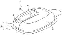
图2图示了根据本发明一种实施方式的系统的例子;Figure 2 illustrates an example of a system according to one embodiment of the invention;
图3图示了根据本发明一种实施方式的递送装置的例子;Figure 3 illustrates an example of a delivery device according to one embodiment of the invention;
图4图示了根据本发明一种实施方式的递送装置;Figure 4 illustrates a delivery device according to one embodiment of the invention;
图5A图示了根据本发明一种实施方式的递送装置的耐用部分;Figure 5A illustrates a durable portion of a delivery device according to one embodiment of the invention;
图5B图示了根据本发明一种实施方式的递送装置的耐用部分的剖视图;Figure 5B illustrates a cross-sectional view of a durable portion of a delivery device according to one embodiment of the invention;
图5C图示了根据本发明一种实施方式的递送装置的耐用部分的剖视图;Figure 5C illustrates a cross-sectional view of a durable portion of a delivery device according to one embodiment of the invention;
图6A图示了根据本发明一种实施方式的递送装置的可丢弃部分;Figure 6A illustrates a disposable portion of a delivery device according to one embodiment of the invention;
图6B图示了根据本发明一种实施方式的递送装置的可丢弃部分的剖视图;Figure 6B illustrates a cross-sectional view of a disposable portion of a delivery device according to one embodiment of the invention;
图6C图示了根据本发明一种实施方式的递送装置的可丢弃部分的剖视图;Figure 6C illustrates a cross-sectional view of a disposable portion of a delivery device according to one embodiment of the invention;
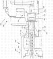
图7图示了根据本发明一种实施方式的医疗装置的一些部分;Figure 7 illustrates some parts of a medical device according to one embodiment of the invention;
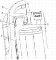
图8图示了根据本发明一种实施方式的医疗装置;Figure 8 illustrates a medical device according to one embodiment of the invention;
图9图示了根据本发明一种实施方式的医疗装置;Figure 9 illustrates a medical device according to one embodiment of the invention;
图10图示了根据本发明一种实施方式的医疗装置;Figure 10 illustrates a medical device according to one embodiment of the invention;
图11图示了根据本发明一种实施方式的医疗装置;Figure 11 illustrates a medical device according to one embodiment of the invention;
图12图示了根据本发明一种实施方式的医疗装置;Figure 12 illustrates a medical device according to one embodiment of the invention;
图13图示了根据本发明一种实施方式的医疗装置;Figure 13 illustrates a medical device according to one embodiment of the invention;
图14图示了根据本发明一种实施方式的医疗装置的一部分;Figure 14 illustrates a portion of a medical device according to one embodiment of the invention;
图15图示了根据本发明一种实施方式的医疗装置的一部分;Figure 15 illustrates a portion of a medical device according to one embodiment of the invention;
图16图示了根据本发明一种实施方式的医疗装置的一部分;Figure 16 illustrates a portion of a medical device according to one embodiment of the invention;
图17图示了根据本发明一种实施方式的医疗装置的一部分;Figure 17 illustrates a portion of a medical device according to one embodiment of the invention;
图18图示了根据本发明一种实施方式的医疗装置的一部分;Figure 18 illustrates a portion of a medical device according to one embodiment of the invention;
图19图示了根据本发明一种实施方式的医疗装置的一部分;Figure 19 illustrates a portion of a medical device according to one embodiment of the invention;
图20图示了根据本发明一种实施方式的医疗装置的一部分;Figure 20 illustrates a portion of a medical device according to one embodiment of the invention;
图21图示了根据本发明一种实施方式的医疗装置的一部分;以及Figure 21 illustrates a portion of a medical device according to one embodiment of the invention; and
图22图示了根据本发明一种实施方式的医疗装置的一部分。Figure 22 illustrates a portion of a medical device according to one embodiment of the invention.
具体实施方式Detailed ways
图1图示了根据本发明实施方式的系统10的概括图。系统10可包括递送装置12。系统10还可包括传感装置14、命令控制装置(CCD)16以及计算机18。在各种不同实施方式中,递送装置12和传感装置14可以固定在患者或用户-患者7的身体5上的期望位置。在图1中,递送装置12和传感装置14固定至用户-患者7的身体5的位置仅作为代表性的、非限制性的例子。应当指出,贯穿本文使用的用户-患者可包括患者-用户、患者、或用户(例如,患者、医疗专业人员或其他治疗患者的人员)。Figure 1 illustrates an overview of a
系统10、递送装置12、传感装置14、CCD16和/或计算机18可类似于(但不限于)下述的美国专利申请(所述美国专利申请已转让给本发明的受让人)中的描述,其中,在此通过引用并入下述每一件申请的全部内容:(i)2005年8月23日提交的、序列号为11/211,095的美国专利申请“Infusion Device AndMethod With Disposable Portion”;(ii)2006年9月1日提交的、序列号为11/515,225的美国专利申请“Infusion Medium Delivery Device And Method WithDrive Device For Driving Plunger In Reservoir”;(iii)2006年10月27日提交的、序列号为11/588,875的美国专利申请“Systems And Methods Allowing ForReservoir Filling And Infusion Medium Delivery”;(iv)2006年10月27日提交的、序列号为11/588,832的美国专利申请“Infusion Medium Delivery Device AndMethod With Drive Device For Driving Plunger In Reservoir”;(v)2006年10月27日提交的、序列号为11/588,847的美国专利申请“Infusion Medium DeliveryDevice And Method With Compressible Or Curved Reservoir Or Conduit”;(vi)2006年10月27日提交的、序列号为11/589,323的美国专利申请“Infusion PumpsAnd Methods And Delivery Devices And Methods With Same”;(vii)2006年11月20日提交的、序列号为11/602,173的美国专利申请“Systems And MethodsAllowing For Reservoir Filling And Infusion Medium Delivery”;(viii)2006年11月20日提交的、序列号为11/602,052的美国专利申请“Systems And MethodsAllowing For Reservoir Filling And Infusion Medium Delivery”;(ix)2006年11月20日提交的、序列号为11/602,428的美国专利申请“Systems And MethodsAllowing For Reservoir Filling And Infusion Medium Delivery”;(x)2006年11月20日提交的、序列号为11/602,113的美国专利申请“Systems And MethodsAllowing For Reservoir Filling And Infusion Medium Delivery”;(xi)2006年11月22日提交的、序列号为11/604,171的美国专利申请“Infusion Medium DeliveryDevice And Method With Drive Device For Driving Plunger In Reservoir”;(xii)2006年11月22日提交的、序列号为11/604,172的美国专利申请“InfusionMedium Delivery Device And Method With Drive Device For Driving Plunger InReservoir”;(xiii)2006年11月30日提交的、序列号为11/606,703的美国专利申请“Infusion Pumps And Methods And Delivery Devices And Methods With Same”;(xiv)2006年11月30日提交的、序列号为11/606,836的美国专利申请“InfusionPumps And Methods And Delivery Devices And Methods With Same”;2006年12月8日提交的、序列号为11/636,384的美国专利申请“Infusion Medium DeliveryDevice And Method With Compressible Or Curved Reservoir Or Conduit”;(xv)2006年12月26日提交的、序列号为11/645,993的美国专利申请“InfusionMedium Delivery Device And Method With Compressible Or Curved ReservoirOr Conduit”;2006年12月26日提交的、序列号为11/645,972的美国专利申请“Infusion Medium Delivery System,Device And Method With Needle InserterAnd Needle Inserter Device And Method”;(xvi)2006年12月26日提交的、序列号为11/646,052的美国专利申请“Infusion Medium Delivery System,Device AndMethod With Needle Inserter And Needle Inserter Device And Method”;(xvii)2006年12月26日提交的、序列号为11/645,435的美国专利申请“InfusionMedium Delivery System,Device And Method With Needle Inserter And NeedleInserter Device And Method”;(xviii)2006年12月26日提交的、序列号为11/646,000的美国专利申请“Infusion Medium Delivery System,Device AndMethod With Needle Inserter And Needle Inserter Device And Method”;以及(xix)2007年6月7日提交的、序列号为11/759,725的美国专利申请“Infusion MediumDelivery Device And Method With Drive Device For Driving Plunger InReservoir”;(xx)2006年11月30日提交的、序列号为11/606,837的美国专利申请“Method And Apparatus For Enhancing The Integrity Of An ImplantableSensor Device”;(xxi)2007年2月5日提交的、序列号为11/702,713的美国专利申请“Selective Potting For Controlled Failure And Electronic Devices EmployingThe Same”;(xxii)2007年8月22日提交的、序列号为11/843,601的美国专利申请“System And Method For Sensor Recalibration”;(xxiii)2007年10月8日提交的、序列号为11/868,898的美国专利申请“Multilayer Substrate”;(xxiv)2007年12月26日提交的、序列号为11/964,649的美国专利申请“System And MethodsAllowing For Reservoir Air Bubble Management”;(xxv)2008年4月29日提交的、序列号为12/111,751的美国专利申请“Systems And Methods For ReservoirFilling”;(xxvi)2008年4月29日提交的、序列号为12/111,815的美国专利申请“Systems And Methods For Reservoir Air Bubble Management”;(xxvii)2007年10月25日提交的、序列号为11/924,402的美国专利申请“Sensor Substrate AndMethod Of Fabricating Same”;(xxviii)2007年10月30日提交的、序列号为11/929,428的美国专利申请“Telemetry System And Method With VariableParameters”;(xxix)2007年12月27日提交的、序列号为11/965,578的美国专利申请“Reservoir Pressure Equalization Systems And Methods”;(xxx)2008年4月22日提交的、序列号为12/107,580的美国专利申请“Automative Filling SystemsAnd Methods”;(xxxi)2007年12月26日提交的、序列号为11/964,663的美国专利申请“Medical Device With Full Options And SelectiveEnablement/Disablement”;(xxxii)2002年6月26日提交的、序列号为10/180,732的美国专利申请“Communication Station And Software For Interfacing With AnInfusion Pump,Analyte Monitor,Analyte Meter,And/or the like”;(xxxiii)2008年4月8日提交的、序列号为12/099,738的美国专利申请“Systems And MethodsAllowing For Reservoir Air Bubble Management”;(xxxiv)2008年2月7日提交的、序列号为12/027,963的美国专利申请“Adhesive Patch Systems AndMethods”;(xxxv)2008年5月15日提交的、序列号为12/121,647的美国专利申请“Multi-Lumen Catheter”;(xxxvi)2008年4月11日提交的、序列号为61/044,269的美国专利临时申请“Reservoir Plunger Head Systems And Methods”;(xxxvii)2008年4月11日提交的、序列号为61/044,292的美国专利申请“ReservoirBarrier Layer Systems And Methods”;(xxxviii)2008年4月11日提交的、序列号为61/044,322的美国专利临时申请“Reservoir Seal Retainer Systems AndMethods”;(xxxix)2008年7月24日提交的、序列号为12/179,502的美国专利申请“Method For Formulating And Immobilizing A Matrix Protein And A MatrixProtein For Use In A Sensor”;(xl)2008年12月16日提交的、序列号为12/336,367的美国专利申请“Needle Insertions Systems And Methods”;(xli)2008年7月1提交的、序列号为12/166,210美国专利申请“Electronic Device For ControlledFailure”;(xlii)2008年11月14日提交的、序列号为12/271,134的美国专利申请“Multilayer Circuit Devices And Manufacturing Methods Using ElectroplatedSacrificial Structures”;(xliii)2008年7月11日提交的、序列号为12/171,971的美国专利申请“Infusion Medium Delivery System,Device And Method WithNeedle Inserter And Needle Inserter Device And Method”;(xliv)2008年8月8日提交的、序列号为12/189,077的美国专利申请“Packaging System”;(xlv)2008年7月24日提交的、序列号为12/179,536的美国专利申请“Real Time Self-Adjusting Calibration Algorithm”;(xlvii)2008年11月24日提交的、序列号为12/277,186的美国专利申请“Infusion Medium Delivery System,Device And Method WithNeedle Inserter And Needle Inserter Device And Method”;(xlviii)2008年9月16日提交的、序列号为12/211,783的美国专利申请“Implantable Sensor Method AndSystem”;(xlix)2008年10月8日提交的、序列号为12/247,945的美国专利申请“Infusion Medium Delivery Device And Method With Drive Device For DrivingPlunger In Reservoir”;(l)2009年1月26日提交的、序列号为12/360,077的美国专利申请“Reservoir Barrier Layer Systems And Methods”;(li)2008年12月29日提交的、序列号为12/345,362的美国专利申请“Reservoir Seal Retainer SystemsAnd Methods”;(lii)2009年1月13日提交的、序列号为12/353,181的美国专利申请“Systems And Methods Allowing For Reservoir Filling And Infusion MediumDelivery”;以及(liii)2009年1月27日提交的、序列号为12/360,813的美国专利申请“Multi-Position Infusion Set Device And Process”;(liv)2009年1月26日提交的、序列号为12/360,077的美国专利申请“Reservoir Barrier Layer Systems AndMethods”;(lv)2009年4月3日提交的、序列号为12/417,976的美国专利申请“Reservoir Plunger Head Systems And Methods”;(lvi)2009年9月2日提交的、序列号为12/553,038的美国专利申请“Insertion Device Systems And Methods”;(lvii)2009年7月8日提交的、序列号为12/499,283的美国专利申请“ReservoirFilling Systems And Methods”;(lviii)2009年8月7日提交的、序列号为12/537,579的美国专利申请“Transfer Guard Systems And Methods”;(lix)2009年12月30日提交的、序列号为12/649,619的美国专利申请“Alignment Systems AndMethods”;(lx)2009年12月30日提交的、序列号为12/650,287的美国专利申请“Engagement And Sensing Systems And Methods”;(lxi)2009年12月30日提交的、序列号为12/650,378的美国专利申请“Connection And Alignment SystemsAnd Methods”;(lxii)2009年3月17日提交的、序列号为12/405,840的美国专利申请“Sterile Device And Method For Producing Same”;(lxiii)2009年3月25日提交的、序列号为12/411,236的美国专利申请“Adhesive Patch Systems AndMethods”;(lxiv)2009年4月6日提交的、序列号为12/419,188的美国专利申请“Implantable Sensor Electrodes And Electronic Circuitry”;(lxv)2009年3月25日提交的、序列号为12/411,247的美国专利申请“Adhesive Patch Systems AndMethods”;(lxvi)2009年12月29日提交的、序列号为12/649,172的美国专利申请“Insertion Device Systems And Methods”;(lxvii)2009年7月2日提交的、序列号为12/497,345的美国专利申请“Infusion Medium Delivery Device And MethodWith Drive Device For Driving Plunger In Reservoir”;(lxviii)2009年6月23日提交的、序列号为12/490,006的美国专利申请“Safety Limits For Closed-LoopInfusion Pump Control”;(lxix)2009年7月31日提交的、序列号为12/533,942的美国专利申请“Reservoir Barrier Layer Systems And Methods”;以及(lxx)2009年8月25日提交的、序列号为12/547,315的美国专利申请“Reservoir Barrier LayerSystems And Methods”,上述美国专利申请的全部内容通过引用并入本文。在其他实施方式中,系统10、递送装置12、传感装置14、CCD16以及计算机18可具有其他合适的配置。
递送装置12可以配置为递送流体介质至用户-患者7的身体5。在各种不同实施方式中,流体介质可包括液体、流体、凝胶体等。在一些实施方式中,流体介质可包括用于治疗疾病或医学疾病的药品或药物。例如,流体介质可包括用于治疗糖尿病的胰岛素,或可包括用于治疗疼痛、癌症、呼吸系统紊乱、HIV等的药物。在一些实施方式中,流体介质可包括营养补充剂、染剂、示踪介质、含盐介质、水合介质等。The
传感装置14可包括用于提供传感器数据或监测器数据的传感器、监测器等。在各种不同实施方式中,传感装置14可配置为检测用户-患者7的状况。例如,传感装置14可包括与用户-患者7的生理状况(例如,血糖水平等)反应的酶和电子装置。
在各种不同实施方式中,传感装置14可以固定至用户-患者7的身体5或者可以在远离递送装置12与用户-患者7的身体5相固定的位置的位置嵌入用户-患者7的身体5。在各种不同其他实施方式中,传感装置14可合并至递送装置12内。在其他实施方式中,传感装置14可以与递送装置分离并分开,并且,例如,可以作为CCD16的一部分。在这样的实施方式中,传感装置14可配置为接收生物样本、分析物等以测量用户-患者7的状况。In various embodiments, the
在其他实施方式中,传感装置14和/或递送装置12可使用闭环系统。使用闭环系统的传感装置和/或递送装置的例子可以在,但不限于,下述参照文献中找到:(i)题为"Electrochemical Sensor And Integrity Tests Therefor”的6,088,608号美国专利;(ii)题为"Implantable Enzyme-Based Monitoring SystemsHaving Improved Longevity Due To Improved Exterior Surfaces"的6,119,028号美国专利;(iii)题为“Implantable Enzyme-Based Monitoring Systems Adaptedfor Long Term Use”的6,589,229号美国专利;(iv)题为"System And MethodFor Providing Closed Loop Infusion Formulation Delivery”的6,740,072号美国专利;(v)题为"Safety Limits For Closed-Loop Infusion Pump Control”的6,827,702号美国专利;(vi)题为"Sensor Substrate And Method Of Fabricating Same”的7,323,142号美国专利;(vii)1999年7月22日提交的、题为"Substrate Sensor"、序列号为09/360,342的美国专利申请;以及(viii)2001年9月7日提交的、题为"Sensing Apparatus and Process”、序列号为60/318,060的美国临时专利申请,在此通过引用并入所有上述参照文献的全部内容。In other embodiments,
在这样的实施方式中,传感装置14可配置为检测用户-患者7的状况,例如,但不限于,血糖水平等。递送装置12可配置为响应传感装置14所检测的状况而递送流体介质。进而,传感装置14可以继续检测用户-患者的新状况,使得递送装置12无限期地响应传感装置14检测的新状况而持续地递送流体介质。在一些实施方式中,传感装置14和/或递送装置12可以配置为仅在一天的部分时候使用闭环系统,例如仅在用户-患者睡觉或清醒时。In such an embodiment, the
递送装置12、传感装置14、CCD16和计算机18中的每一个可包括用于与系统10的其他元件通信的发送电子装置、接收电子装置或收发电子装置。传感装置14可以配置为将传感器数据或监测器数据发送至递送装置12。传感装置14还可以配置为与CCD16通信。递送装置12可包括配置为分析所述传感器数据并基于所述传感器数据和/或预编程的递送程序将流体介质递送至用户-患者7的身体5的电子装置和软件。Each of
CCD16和计算机18可包括配置为执行处理、执行递送程序存储以及控制递送装置12的电子装置和其他元件。通过在CCD16和/或计算机18内包含控制功能,递送装置12可以采用更简化的电子装置制造。然而,在一些实施方式中,递送装置12可包括所有的控制功能,并且可以在没有CCD16和计算机18的情形下工作。在各种不同实施方式中,CCD16可以是便携式电子装置。在各种不同实施方式中,递送装置12和/或传感装置14可以配置为发送数据至CCD16和/或计算机18以通过CCD16和/或计算机18显示或处理所述数据。
在一些实施方式中,传感装置14可集成到CCD16中。这样的实施方式可允许用户-患者通过提供例如他或她的血液样本给传感装置14来评估他或她的状况来监测状况。在一些实施方式中,传感装置14和CCD16可以在没有使用或没必要使用递送装置12和传感装置14和/或CCD16之间的电线或电缆连接的情形下用于确定所述用户-患者的血液和/或体液的血糖水平。In some embodiments,
在一些实施方式中,CCD16可以用于向用户-患者提供信息,这有助于所述用户-患者后续使用药物递送系统。例如,CCD16可以向用户-患者提供信息以使所述用户-患者可以确定将要施用至其身体的药品的速率或剂量。在其他实施方式中,CCD16可以向递送装置12提供信息以控制施用至所述用户-患者身体的药品的速率或剂量。In some embodiments, the
通信和/或控制能力类型、以及装置功能设置和/或程序选择的例子可以在下述参照文献中找到:(i)2003年5月27日提交的、题为“External Infusion Devicewith Remote Programming,Bolus Estimator and/or Vibration AlarmCapabilities”、序列号为10/445,477的美国专利申请;(ii)2003年5月5日提交的、题为“Handheld Personal Data Assistant(PDA)with a Medical Device and Methodof Using the Same”、序列号为10/429,385的美国专利申请;以及(iii)2001年3月21日提交的、题为“Control Tabs for Infusion Devices and Methods of Usingthe Same”、序列号为09/813,660的美国专利申请,在此通过引用并入所有上述参照文献的全部内容。Examples of types of communication and/or control capabilities, and device feature set and/or programming options can be found in the following references: (i) Filed May 27, 2003, entitled "External Infusion Device with Remote Programming, Bolus Estimator and/or Vibration Alarm Capabilities", U.S. Patent Application Serial No. 10/445,477; (ii) filed May 5, 2003, entitled "Handheld Personal Data Assistant (PDA) with a Medical Device and Method of Using the Same" , U.S. Patent Application Serial No. 10/429,385; and (iii) U.S. Patent Application Serial No. 09/813,660, filed March 21, 2001, and entitled "Control Tabs for Infusion Devices and Methods of Using the Same" , which are hereby incorporated by reference in their entirety.
图2图示了根据本发明实施方式的系统10的例子。根据图2中所图示的实施方式,系统10包括递送装置12和传感装置14。根据本发明实施方式的递送装置12可包括可丢弃外壳20、耐用外壳30以及储液器系统40。递送装置12还可包括输注通道50。Figure 2 illustrates an example of a
递送装置12的在其工作期间通常接触流体介质或通常接触用户-患者身体的元件可看作是递送装置12的可丢弃部分。例如,递送装置12的可丢弃部分可包括可丢弃外壳20和储液器系统40。可以建议递送装置12的所述可丢弃部分在使用指定次数后丢弃。Elements of the
另一方面,递送装置12的在其工作期间通常不接触流体介质或通常不接触用户-患者身体的元件可看作是递送装置12的耐用部分。例如,递送装置12的耐用部分可包括耐用外壳30、电子装置(图2中未示出)、具有马达和驱动联动装置的驱动装置(图2中未示出)等。递送装置12的耐用外壳部分的元件由于在递送装置12正常工作期间与用户-患者或流体介质免于接触而通常未被污染,因而可以保留以与递送装置12更换后的可丢弃部分一起重复使用。On the other hand, elements of the
在各种不同实施方式中,所述可丢弃外壳20可支撑所述储液器系统40且具有配置为与用户-患者身体固定的底表面(在图2中朝下并进入页面)。在所述可丢弃外壳20的底表面和所述用户-患者的皮肤之间的界面上可以采用粘合剂以将所述可丢弃外壳20粘附至所述用户-患者的皮肤。在各种不同实施方式中,所述粘合剂可以设置在所述可丢弃外壳20的底表面上,用可剥离覆盖层覆盖所述粘合剂材料。在这种方式下,所述覆盖层可以被剥离以曝露所述粘合剂材料,并且所述可丢弃外壳20的粘合剂面可以紧靠用户-患者放置,例如紧靠所述用户-患者的皮肤。因而,在一些实施方式中,递送装置12可以附着在所述用户-患者的皮肤。In various embodiments, the
在其他实施方式中,可丢弃外壳20和/或递送装置12的其余部分可佩戴或者以别的方式附着在所述用户-患者的衣物上或衣物下。类似地,递送装置12可以通过任何合适的方式支撑,例如,但不限于,支撑在皮带上、在口袋内等等。这样的递送装置12的代表性例子,以及一般的递送装置可以包括,但不限于:MiniMed Paradigm522胰岛素泵、MiniMed Paradigm722胰岛素泵、MiniMed Paradigm515胰岛素泵、MiniMed Paradigm715胰岛素泵、MiniMedParadigm512R胰岛素泵、MiniMed Paradigm712R胰岛素泵、MiniMed508胰岛素泵、MiniMed508R胰岛素泵、及其任意其他衍生装置。In other embodiments, the
储液器系统40可配置用于容纳或保存流体介质,例如,但不限于,胰岛素。在各种不同实施方式中,储液器系统40可包括用于容纳流体介质的中空的内部容积,例如,但不限于:圆柱形容积、管状容积等等。在一些实施方式中,储液器系统40可以作为用于容纳流体介质的药筒或药罐。在各种不同实施方式中,储液器系统40可以重复填充流体介质。在其他的实施方式中,储液器系统40可以预填充流体介质。
储液器系统40可以由可丢弃外壳20以任何合适的方式支撑。例如,可丢弃外壳20可配备有用于支撑储液器系统40的凸出物或支柱(未示出)或槽状特征(未示出)的。在一些实施方式中,储液器系统40可以由可丢弃外壳20以允许储液器40从可丢弃外壳20移走并使用另外的储液器替换的方式支撑。可选地,或附加地,储液器系统40可以通过合适的粘合剂、带或其他连接结构固定至可丢弃外壳20。
在各种不同实施方式中,储液器系统40可包括用于允许流体介质流入和/或流出所述储液器系统40的内部容积的至少一个端口41。在一些实施方式中,输注通道50可包括连接器56、管54以及针装置52。输注通道50的连接器56可以与储液器系统40的端口41可连接。在各种不同实施方式中,可丢弃外壳20可配置有靠近储液器40的端口41的开口用于允许输注通道50的连接器56选择性地与储液器系统40的端口41连接和断开。In various embodiments, the
在各种不同实施方式中,储液器系统40的端口41可以使用隔膜覆盖或支撑隔膜(图2中未示出),例如自密封隔膜等等。所述隔膜可以配置为在其未被刺穿时防止流体介质通过端口41从储液器系统40流出。此外,在各种不同实施方式中,输注通道50的连接器56可包括针,用于刺穿覆盖储液器系统40的端口41的隔膜以允许流体介质从储液器系统40的内部容积流出。In various implementations, the
针/隔膜连接器的例子可以在2003年12月22日提交的、题为“ReservoirConnector”、序列号为10/328,393的美国专利申请中找到,在此通过引用将所述申请的全部内容并入本文。在其他的可选实施方式中,可以使用非隔膜连接器,例如鲁尔锁(Luer locks)等等。在各种不同实施方式中,输注通道50的针装置52可包括能够刺穿用户-患者皮肤的针。而且,在各种不同实施方式中,管54将连接器56与针装置52连接并且可以是中空的,这样,输注通道50能够提供允许流体介质从储液器系统40递送至用户-患者身体的通道。Examples of needle/septum connectors can be found in U.S. Patent Application Serial No. 10/328,393, filed December 22, 2003, entitled "Reservoir Connector," which is hereby incorporated by reference in its entirety. This article. In other alternative embodiments, non-septum connectors such as Luer locks and the like may be used. In various embodiments, the
根据本发明各种不同实施方式的递送装置12的耐用外壳30包括配置成与可丢弃外壳20配合并且固定的外罩壳。耐用外壳30和可丢弃外壳20可配备有相应成形的凹槽、凹口、键形物或其他合适特征,这允许通过手动将所述两个外壳按压在一起、扭转或螺纹连接、以摩擦装配连接、以可滑动连接、和/或机械领域熟知的其他合适的连接所述部件的方式容易地将这两部分连接在一起。The
在各种不同实施方式中,可采用扭转动作将耐用外壳30和可丢弃外壳20彼此连接。耐用外壳30和可丢弃外壳20可以配置为当施加足够大作用力将所述两个外壳彼此分离时彼此可分开。例如,在一些实施方式中,可丢弃外壳20和耐用外壳30可以通过摩擦装配扣在一起。在各种不同实施方式中,合适的密封(例如,O型环密封)可以沿耐用外壳30和/或可丢弃外壳20的周围边缘放置以提供防止水进入耐用外壳30和可丢弃外壳20之间的密封。In various embodiments, a twisting action may be used to connect the
递送装置12的耐用外壳30可支撑驱动装置(图2中未示出),所述驱动装置可包括马达和驱动装置联动部分。所述驱动装置可以配置为向储液器系统40内的流体介质施加作用力来使流体介质流出储液器系统40并进入输注通道(例如,输注通道50)以递送至用户-患者。例如,在一些实施方式中,在耐用外壳30内可以安装电驱动马达84(参见图5B和图5C),通过适当的联动装置将马达84与连接至布置于储液器系统40内的柱塞头(参见图6A至图6C)的柱塞臂(参见图6A至图6C)操作性地连接。所述电驱动马达可以配置为沿使流体介质流出储液器系统40的端口41并流向用户-患者的方向驱动所述柱塞头。The
另外,在一些实施方式中,马达84可以是可控的,从而反转方向以移动所述柱塞臂60和柱塞头使流体从患者抽吸至储液器系统40中。马达84可以布置在耐用外壳30内而储液器系统40可相应地布置在可丢弃外壳20上,以便当用户-患者将递送装置12的耐用外壳30与可丢弃外壳20连接时自动发生通过适当的联动装置将所述马达84与所述柱塞头可操作接合。联动和控制结构的其他例子可以在,但不限于,下述文献中找到:在2001年3月21日提交的、题为“Control Tabs for Infusion Devices and Methods of Using the Same”、序列号为09/813,660的美国专利申请;2005年8月23日提交的、题为“Infusion Device andMethod with Disposable Portion”、公开号为2006/0264894(序列号为11/211,095)的美国专利文献;2005年8月23日提交的、题为“Infusion Device and MethodWith Drive In Separable Durable Housing Portion”、序列号为11/210,467的美国专利申请;2005年8月23日提交的、题为“Pump Assembly and Method ForInfusion Device”、序列号为11/211,150的美国专利申请;2005年8月23日提交的、题为“Reservoir Support And Method For Infusion Device”、序列号为11/210,455的美国专利申请;以及2001年3月27日提交的、题为“Methods,Apparatuses,and Uses for Infusion Pump Fluid Pressure and Force Detection”、专利号为6,485,465的美国专利,在此通过引用并入所有上述文献的全部内容。Additionally, in some embodiments, the
在各种不同实施方式中,耐用外壳30和可丢弃外壳20可以由保持其形状,如上所述,又提供足够的挠性和弹性以有效地连接在一起和分离的合适的刚性材料制成。为了与皮肤合适的相容,可以对可丢弃外壳20的材料进行选择。例如,递送装置12的可丢弃外壳20和耐用外壳30可以由任何合适的塑料、金属、合成材料等制成。可丢弃外壳20可以由与耐用外壳30同种或不同的材料制成。在一些实施方式中,可丢弃外壳20和耐用外壳30可以通过喷射模塑工艺或其他模塑工艺、加工工艺或这些工艺的组合来制造。In various embodiments, the
例如,可丢弃外壳20可由相对挠性的材料制成,例如弹性硅、塑料、橡胶、合成橡胶等等。通过由能够随用户-患者的皮肤而弯曲的材料形成可丢弃外壳20,当可丢弃外壳20固定至所述用户-患者皮肤时可以获得较高的用户-患者舒适度。而且,挠性的可丢弃外壳20可以使用户-患者身体上的可以固定可丢弃外壳20的部位的选择增加。For example, the
在图2所示的实施方式中,递送装置12通过传感装置14的连接元件17与传感装置14连接。传感装置14可包括传感器15,传感器15包括任何合适的生物或环境传感装置,这取决于待通过递送装置12给药的治疗的性质。例如,在向糖尿病患者递送胰岛素的场景中,传感器15包括血糖传感器或类似的传感器。In the embodiment shown in FIG. 2 , the
在一些实施方式中,传感器15可包括持续的葡萄糖传感器。所述持续的葡萄糖传感器可植入到用户-患者身体内。在其他实施方式中,所述持续的葡萄糖传感器可以置于外部,例如,置于用户-患者的皮肤上,或附着在用户-患者的衣物上。在这样的实施方式中,可以持续地从用户-患者抽取流体并由持续的葡萄糖传感器检测。在各种不同实施方式中,所述持续的葡萄糖传感器可以配置为持续地检测和/或与CCD16通信。在其他实施方式中,所述持续的葡萄糖传感器可以配置为间歇地检测和/或与CCD16通信,例如每隔几分钟检测葡萄糖水平并发送信息。在各种不同实施方式中,所述持续的葡萄糖传感器可以使用葡糖氧化酶。In some embodiments,
传感器15可以是固定在用户-患者皮肤的外部传感器,或者,在其他实施方式中,可以是位于所述用户-患者身体内植入部位的可植入传感器。在其他的可选实施方式中,所述传感器可以作为所述输注插管和/或针的一部分或可以沿所述输注插管和/或针的侧边进行设置,例如,如2005年6月8日提交的、题为“Dual Insertion Set”、序列号为11/149,119的美国专利申请所示,在此通过引用将所述申请的全文并入。在图2所示的例子中,传感器15为具有可丢弃针垫的外部传感器,可丢弃针垫包括用于刺穿用户-患者皮肤的针以及与用户-患者的生理状况(例如血糖水平等)反应的酶和/或电子装置。在这种方式下,可向递送装置12提供来自传感器15的传感数据,所述传感器15在远离递送装置12与用户-患者相固定的位置的部位与所述用户-患者固定。
尽管图2示出的实施方式可包括由连接元件17连接的传感器15用于向放置于递送装置12的耐用外壳30内的传感器电子装置(图2中未示出)提供传感器数据,其他实施方式可采用放置于递送装置12内的传感器15。另外其他的实施方式可采用具有发送器的传感器15,该发送器用于通过无线通信链路与放置于递送装置12的耐用外壳30内的接收电子装置(图2中未示出)传递传感数据。在各种不同实施方式中,传感器15与递送装置12的耐用外壳30内的接收电子装置之间的无线连接可包括射频(RF)连接、光学连接或另外合适的无线通信链路。其他实施方式不需要采用传感装置14,作为替代,可以在不使用传感数据的情形下提供流体介质递送功能。While the embodiment shown in FIG. 2 may include a
如上所述,通过将递送装置12的可丢弃元件与耐用元件分开,所述可丢弃元件可以布置在可丢弃外壳20上,而耐用元件可以布置在可分离的耐用外壳30内。这样,在递送装置12使用预定次数后,可丢弃外壳20可以与耐用外壳30分离,以便可丢弃外壳20可以以合适的方式处理。耐用外壳30随后可以与新的(未使用的)可丢弃外壳20配合用来对用户-患者进行进一步的递送操作。As noted above, by separating the disposable elements of the
图3图示了根据本发明另一种实施方式的递送装置12的例子。图3的实施方式的递送装置12与图2的实施方式的递送装置12类似。尽管图2所示的实施方式中的递送装置12设置耐用外壳30来覆盖储液器系统40,在图3的实施方式中递送装置12设置耐用外壳30与可丢弃外壳20固定而不是覆盖储液器系统40。图3所示实施方式的递送装置12包括可丢弃外壳20,并且根据图3所示实施方式的可丢弃外壳20包括基部21和储液器保持部24。在一种实施方式中,基部21和储液器保持部24可以形成为单一的、整体结构。Figure 3 illustrates an example of a
可丢弃外壳20的基部21可以配置为与用户-患者的身体可固定。可丢弃外壳20的储液器保持部24配置为容纳储液器系统40。可丢弃外壳20的储液器保持部24可以配置为具有当储液器系统40容纳在储液器保持部24内时允许从储液器保持部24的外侧进入储液器系统40的端口41的开口。耐用外壳30可以配置为与可丢弃外壳20的基部21可连接且可分开。图3所示实施方式中的递送装置12包括与储液器系统40内的柱塞头(图3中未示出)连接的或可连接的柱塞臂60。The
图4图示了图3所示实施方式的递送装置12的另一视图。图4所示实施方式的递送装置12包括可丢弃外壳20、耐用外壳30、以及输注通道50。图4所示实施方式中的可丢弃外壳20包括基部21、储液器保持部24以及可剥离覆盖层25。可剥离覆盖层25可覆盖基部21的底表面22上的粘合剂材料。可剥离覆盖层25可以配置为由用户-患者可剥离来曝露基部21的底表面22上的粘合剂材料。在一些实施方式中,在基部21的底表面22上可以具有由可剥离层分隔的多层粘合剂层。FIG. 4 illustrates another view of the
根据图4所示的本发明实施方式的输注通道50包括针58而非图2实施方式所示的连接器56、管54以及针装置52。可丢弃外壳20的基部21可配备有与针58的尖端对齐的开口或可刺穿的壁,从而当延伸时允许针58穿过基部21并进入基部21之下的用户-患者的皮肤。在这种方式中,针58可用于刺穿用户-患者的皮肤并将流体介质递送至所述用户-患者。The
可选地,针58可以延伸穿过中空插管(图4中未示出),以便当使用针58刺穿用户-患者皮肤时,所述中空插管的一端由针58引导进入所述用户-患者的皮肤。此后,针58可以移走,就位留下所述中空插管,其中所述插管的一端置于用户-患者的身体内而所述插管的另一端与储液器系统40内的流体介质以流体流连接。因此,可以将流体介质从储液器系统40输送至用户-患者身体。Optionally, the
图5A图示了根据本发明一种实施方式的递送装置12(例如,图3)的耐用部分8。图5B图示了根据本发明一种实施方式的耐用部分8的剖视图。图5C图示了根据本发明一种实施方式的耐用部分8的另一剖视图。参见图5A、图5B、和图5C,在各种不同实施方式中,耐用部分8可包括耐用外壳30、以及驱动装置80。驱动装置80可包括马达84和驱动装置联动部分82。FIG. 5A illustrates
在各种不同实施方式中,耐用外壳30可包括用于容纳马达84、驱动装置联动部分82、其他电子线路以及电源(在图5A、图5B和图5C中未示出)的内部容积。而且,在各种不同实施方式中,耐用外壳30可配置有用于容纳柱塞臂60(参见图3)的开口32。此外,在各种不同实施方式中,耐用外壳30可包括用于与可丢弃外壳20的基部21(例如,图3)连接的一个或一个以上连接部件34,例如,键形物、插入孔等。In various embodiments,
图6A图示了根据本发明一种实施方式的递送装置12(例如,图3)的可丢弃部分9。图6B图示了根据本发明一种实施方式的可丢弃部分9的剖视图。图6C图示了根据本发明一种实施方式的可丢弃部分9的另一剖视图。参见图6A、图6B和图6C,在各种不同实施方式中,可丢弃部分9包括可丢弃外壳20、储液器系统40、柱塞臂60、以及柱塞头70。柱塞头70可以由溴化丁基橡胶、硅橡胶、或任何其他合适的材料和/或以上材料的任何衍生物制得。在一些实施方式中,可丢弃外壳20可包括基部21和储液器保持部24。在各种不同实施方式中,基部21可包括具有一个或一个以上连接部件26(例如,键形物、凹槽等等)的顶表面23,所述连接部件26用来与耐用外壳30(例如,图5B)的实施方式的一个或一个以上连接部件34连接。Figure 6A illustrates the
在各种不同实施方式中,储液器系统40可以容纳在可丢弃外壳20的储液器保持部24之内,并且储液器系统40可以配置为保存流体介质。而且,在各种不同实施方式中,柱塞头70可以至少部分地安放在储液器系统40内并可以在储液器系统40内可移动以允许流体介质填充入储液器系统40和将流体介质从储液器系统40内推出。在一些实施方式中,柱塞臂60可以连接至柱塞头70或与柱塞头70可连接。In various implementations, the
另外,在一些实施方式中,柱塞臂60的一部分可以延伸至可丢弃外壳20的储液器保持部24的外面。在各种不同实施方式中,柱塞臂60可具有用于与驱动装置80(例如,图5C)的驱动装置联动部分82配合的配合部分。参见图5C和图6C,在一些实施方式中,耐用外壳30可以卡扣装配在可丢弃外壳20上,于是驱动装置联动部分82自动接合柱塞臂60的所述配合部分。Additionally, in some embodiments, a portion of the
当耐用外壳30与可丢弃外壳20结合并且驱动装置联动部分82与柱塞臂60接合或配合时,可以控制马达84来驱动驱动装置联动部分82。从而,可以移动柱塞臂60使得柱塞头70在储液器系统40内移动。当储液器系统40的内部容积充分地填充有流体介质并且提供了从储液器系统40到用户-患者身体的输注通道时,柱塞头70可以在储液器40内移动以通过所述输注通道将流体介质从储液器器系统40内推至所述用户-患者。When the
在各种不同实施方式中,一旦储液器系统被充分排空或者另外需要更换,用户-患者可以简单地将耐用外壳30从可丢弃外壳20移走,并采用具有新储液器的新可丢弃部分更换可丢弃部分9(包括储液器系统40)。所述耐用外壳30可以与所述新可丢弃部分的新可丢弃外壳连接,并且包括所述新可丢弃部分的递送装置可以固定至用户-患者的皮肤,或者以别的方式附着至所述用户-患者。In various embodiments, once the reservoir system is sufficiently emptied or otherwise needs to be replaced, the user-patient can simply remove the
在各种不同其他实施方式中,储液器系统40可以重新填充流体介质,而不是每当储液器系统40被排空时更换整个可丢弃部分9。在一些实施方式中,储液器系统40在其保留在可丢弃外壳20的储液器保持部24(例如,图6B)内的同时可以进行重新填充。此外,在各种不同实施方式中,储液器系统40可以用新的储液器(未示出)更换,而可丢弃外壳20可以与所述新的储液器一起重新使用。在这样的实施方式中,所述新的储液器可以插入至所述可丢弃部分9。In various other embodiments, the
参见图3、图5A、图6B和图6C,在各种不同实施方式中,递送装置12可包括储液器状态电路(未示出),并且储液器40可包括储液器电路(未示出)。在各种不同实施方式中,所述储液器电路存储以下至少一种信息,例如,但不限于:(i)识别储液器系统40的标识字符串;(ii)储液器系统40的制造商;(iii)储液器系统40的内容;(iv)储液器系统40中内容的数量;或类似的信息。在一些实施方式中,递送装置12可包括储液器状态电路,并且所述储液器状态电路可配置为当所述储液器系统40插入至可丢弃部分9时从所述储液器电路读取数据。3, 5A, 6B, and 6C, in various embodiments,
在各种不同实施方式中,所述储液器状态电路还可以配置为在储液器系统40的至少部分内容被输送出储液器系统40之后存储数据至所述储液器电路以更新所述储液器电路中的信息。所述信息可以涉及,但不限于,储液器系统40中剩余的流体介质的数量、已经递送的流体介质的数量、柱塞头60的位置、储液器系统内的压强、或类似的信息。In various implementations, the reservoir status circuit may also be configured to store data to the reservoir circuit to update the reservoir status circuit after at least a portion of the contents of the
在一些实施方式中,所述储液器状态电路可以配置为当储液器系统40插入至可丢弃部分9时存储数据至所述储液器电路以更新所述储液器电路中关于储液器系统40中剩余内容的数量的信息。在一些实施方式中,递送装置12可包括储液器状态电路,储液器系统40可包括所述储液器电路,并且所述储液器状态电路基于由该储液器状态电路从所述储液器电路读取的信息可以选择性地禁止使用所述递送装置12或者可以选择性地提供警告信号。In some embodiments, the reservoir status circuit may be configured to store data to the reservoir circuit when the
各种不同的实施方式主要涉及针插入器或插入装置和方法以及医疗装置,例如,但不限于,传感器、监测器和输注介质递送系统、包括这样的针插入装置和方法的装置及方法。该针插入装置和方法可用于将针或插管插入穿过用户-患者的皮肤,从而,例如提供用于通过针或插管中的中空通道输送输注介质并输送至用户-患者体内的流体流通道和/或将来自该用户-患者的液体输送至一个或多个传感器元件。如上所述,本发明的实施方式可配置为提供可靠、节约成本且易于使用的装置,用于以具有微创效果的方式将针或插管插入用户-患者特定深度。The various embodiments generally relate to needle inserters or insertion devices and methods and medical devices such as, but not limited to, sensors, monitors, and infusion medium delivery systems, devices and methods including such needle insertion devices and methods. The needle insertion device and method may be used to insert a needle or cannula through the skin of a user-patient, thereby, for example, providing fluid for delivery of an infusion medium through a hollow passage in the needle or cannula and into the user-patient. flow channel and/or deliver fluid from the user-patient to one or more sensor elements. As noted above, embodiments of the present invention may be configured to provide a reliable, cost-effective, and easy-to-use device for inserting a needle or cannula to a user-patient specific depth in a minimally invasive manner.
此外,实施方式可配置为当中空针或插管插入用户-患者时在储液器和用户-患者之间建立用于流体输送的连续流体流通道。根据本发明的实施方式的针插入装置可以与输注介质递送系统的一部分使用、与输注介质递送系统的一部分可连接和可分离、或者可并入输注介质递送系统的一部分。例如,针插入装置可连接至泵型递送装置的基部结构以插入针,随后所述针插入装置可从该基部结构中移走,因此,该递送装置的另一外壳部分(包括组件,例如,但不限于,储液器和泵或驱动装置)可连接至该基部结构用于操作。Furthermore, embodiments may be configured to establish a continuous fluid flow path for fluid delivery between the reservoir and the user-patient when the hollow needle or cannula is inserted into the user-patient. Needle insertion devices according to embodiments of the present invention may be used with, attachable to and detachable from, or incorporated into a portion of an infusion medium delivery system. For example, a needle insertion device may be connected to a base structure of a pump-type delivery device to insert a needle, from which the needle insertion device may then be removed, whereby another housing portion of the delivery device (comprising components such as, for example, Without limitation, a reservoir and a pump or drive) may be connected to the base structure for operation.
可选地,针插入装置可合并至包括如上所述的其他组件的所述另一外壳部分。在另一些实施方式中,所述针插入装置可与注射部位模块或其他外壳可连接(和可释放)或者合并入所述注射部位模块或其他外壳,所述其他外壳由例如柔性管连接至医疗装置(例如,但不限于输注介质递送装置)的其他部件。在另一些实施方式中,针插入器装置可配置成与除输注介质递送系统之外的系统一起使用,例如,但不限于传感器和监测器系统等等。Optionally, the needle insertion device may be incorporated into said other housing part comprising other components as described above. In other embodiments, the needle insertion device may be connectable (and releasable) to or incorporated into an injection site module or other housing connected to a medical device by, for example, flexible tubing. Other components of a device such as, but not limited to, an infusion medium delivery device. In other embodiments, the needle inserter device may be configured for use with systems other than infusion medium delivery systems, such as, but not limited to, sensor and monitor systems and the like.
参照本发明公开的实施方式所描述的结构和方法应用任何合适的装置或系统中,在所述任何合适的装置或系统中某些时间段未以流体流连通连接的两个部件按照使流体从一个部件流向另一个部件的方式连接在一起。在一种示例性实施方式中,参照下述内容对所述结构和方法进行描述:包括用于容纳输注介质的流体储液器的第一部件可连接至包括注射部位结构的第二部件,在所述注射部位结构中,中空针或插管插入或可以插入用户-患者,用于将流体介质输送至用户-患者。然而,可采用根据本发明的实施方式的连接结构来将任何两个(或更多个)部件连接到一起,实现彼此间流体流连通。The structures and methods described with reference to the disclosed embodiments of the present invention have application in any suitable device or system in which two components not connected in fluid flow communication for some period of time are in accordance with the flow of fluid from Connected together by the way one part flows into another. In an exemplary embodiment, the structures and methods are described with reference to a first component comprising a fluid reservoir for containing an infusion medium connectable to a second component comprising an injection site structure, In said injection site configuration, a hollow needle or cannula is or can be inserted into the user-patient for delivery of a fluid medium to the user-patient. However, connection structures according to embodiments of the present invention may be employed to connect any two (or more) components together in fluid flow communication with each other.
在图7至图12中,参照第一部件102和第二部件103描述了以流体流连通方式将两个部件连接的结构100和方法。第一部件102可以包括基部106上的外壳104。外壳104可以与基部106一体成型,或者可形成为以固定关系与基部106连接的单独结构。外壳104和基部106各自可以由任何合适的刚性材料制成,包括,但不限于塑料、金属、陶瓷、合成材料等。In FIGS. 7-12 , a
外壳104可包括注射部位部分105,注射部位部分105包括注射部位结构,在注射部位结构中中空针或插管可插入用户-患者用于输送流体介质至用户-患者或者输送来自用户-患者的流体介质。外壳104可由合适的强度和耐用度的材料制成,例如,但不限于塑料、金属、玻璃等。在其他实施方式中,替代注射部分或者除了注射部位以外,外壳104可包括用于输送、容纳和/或处理流体介质的任何合适的结构,或者可以是所述合适的结构的部分,或者可以与所述合适的结构操作连接。The housing 104 may include an
第二部件103还可包括外壳108,其在图示的实施方式中可包括用于容纳流体介质的储液器107。储液器107可由之前关于储液器系统40(例如图1至图6C)所述的材料配置和/或制成。第二部件103可容纳在外部外壳109中或者以别的方式被外部外壳109覆盖,外部外壳109配置成连接至基部106。外部外壳109可配置成通过任何合适的连接结构连接至第一部件102的基部106。The
在特定的实施方式中,外部外壳109和基部106中的至少一者可包括一个或多个柔性棘爪、凸出物、凹槽等,用于接合和/或收纳所述外部外壳109和基部106中另一者的一个或多个相应的棘爪、凸出物、凹槽等,以提供合适的连接结构。可选地或者附加地,该连接结构可包括粘合材料或者其他合适的连接件。In particular embodiments, at least one of the
在其他实施方式中,外壳108可以是容纳传感部件的传感器外壳(未示出),或者可连接至该传感器外壳。而在另一些实施方式中,外壳108可容纳用于输送、容纳和/或处理流体介质的任何合适的结构,或者可以属于所述合适的结构,或者可以与所述合适的结构操作连接。外壳108可由任何合适的刚性材料制成,包括,但不限于塑料、金属、陶瓷、合成材料等。In other implementations,
外壳104可具有插孔结构110或者可连接至插孔结构110。插孔结构110可具有通往插孔结构110内的室114的开口112。在一些实施方式中,插孔结构110可以是外壳104的一部分,该部分邻近外壳104的容纳注射部位部分105的部分。在其他实施方式中,插孔结构110可包括连接至外壳104的另一外壳。The housing 104 may have a
插孔结构110可包括位于室114内的第一隔膜116,并且可在室114内朝向或背离开口112移动。插孔结构110还可包括偏置机构118,偏置机构118可以朝向开口112的方向对第一隔膜116施加偏压力。偏置机构118可安置成使第一隔膜116紧靠开口112。可邻近开口112设置一个或多个环形凸出物或者一个或多个合适地成形或放置的凸出物120来阻止第一隔膜116被偏置机构118的力通过开口112推出室114。The
第一隔膜116可具有前表面116a,当第一隔膜116被偏置机构118抵靠在开口112时,前表面116a至少部分地通过开口112暴露。第一隔膜116可具有朝向室114的内部的后表面116b。第一隔膜116可由可以被针刺穿的任何合适的材料制成,例如,但不限于,天然或合成的橡胶材料、硅等。在一些实施方式中,第一隔膜116可由能够在针刺穿第一隔膜116并随之从第一隔膜116撤除后自行密封的自密封材料制成。The
一些实施方式中,偏置机构118可以是在室114内位于第一隔膜116的与前表面116a相反的一侧的螺旋弹簧。在另一些实施方式中,可以以使第一隔膜116朝向开口112偏置的任何合适的方式设置偏置机构118。这些方式可包括,但不限于,其他类型的弹簧、室114内的加压流体、具有天然或内置弹力的从第一隔膜116延伸的可折叠裙状结构、在与另一化学品或物质接触后膨胀或者在应用来自诸如热、激光或其他辐射源等之类的能量源的能量后膨胀的化学品、物质。例如,一些实施方式中,第一隔膜116可具有柔韧的手风琴样的结构以使所述裙状结构扩展和收缩。In some embodiments, the
针124可支撑在室114内。针124可以是中空的,并且可以具有朝向第一隔膜116后表面116b的尖端124a。一些实施方式中,针124可以支撑在偏置机构118内,使得针124的纵轴方向基本平行于偏置机构118的纵轴方向延伸。
针124可由位于插孔结构110内的支撑结构来支撑。一些实施方式中,该支撑结构可以是与插孔结构110一体成型的壁。例如,该支撑结构可以位于室114的相对于室114中开口112所在端的另一端上。在另一些实施方式中,该支撑结构可以是相对于插孔结构110基本固定并且能够以与插孔结构110基本固定的关系支撑针124的任何合适的结构。
针124可由任何合适的刚性材料制成,包括,但不限于塑料、金属、陶瓷、合成材料等,并且具有沿针124的长度方向延伸的中空通道。针124中的中空通道可在针124的尖端124a处开口,并可在沿着针124的长度方向的另一位置124b处开口,例如,但不限于,尖端124a相反侧的针端。针124中的中空通道可提供针124的尖端124a和针124的开口124b之间的流体流通道。一些实施方式中,针124的开口124b可以以流体流连通的方式与注射部位部分105中的歧管128连接。
第二部件103的外壳108可包括连接部130,连接部130具有中空的内室132和进入内室132的开口134。第二隔膜136可由外壳108支撑以密封开口134。第二隔膜136可以以相对于外壳108固定的关系支撑在外壳108中的,例如,内室132的一端。The
外壳108的连接部130可具有合适的形状和尺寸,从而当第一部件102和第二部件103连接在一起的时候,外壳108的连接部130至少部分地装配在第一部件102中的插孔结构110的开口112内。在图7和图8的图形中,第一部件102和第二部件103显示为分开的、断开的关系,其中外壳108的连接部130在插孔结构110的开口112外。通过将第一部件102和第二部件103移动到一起以将连接部130插入外壳108的开口112,连接部130的端面可以抵靠于第一隔膜116。这可导致可移动的第一隔膜116相对于外壳108逆着偏置机构118的力朝向室114的内部移动。随着第一隔膜116向外壳108的内部移动,针124的尖端124a可刺穿第一隔膜116。第一部件102和第二部件103一起连续相对移动可使针124的尖端124a穿过第一部件102中的第一隔膜116,然后刺穿并穿过第二部件103中的第二隔膜136。The connecting
当第一部件102和第二部件103结合在一起时(例如,图9),连接部130的至少一部分可延伸入插孔结构110内。参照图8和图9,针124可以刺穿第一隔膜116和第二隔膜136从而在连接部130的内室132与歧管128或位于针124的开口124b处的其他结构之间形成流体流通道。插孔结构110和连接部130可设置有配合连接器,在第一部件102和第二部件103结合在一起的时候,如图9所示,所述配合连接器提供例如卡扣连接或摩擦连接。一些实施方式中,所述配合连接器可包括位于插孔结构110和连接部130中的一者或另一者上的凸出物(未示出)。插孔结构110和连接部130中的另一者可包括凹槽或凹痕(未示出),配置成在连接部130延伸入插孔结构110内合适距离之后以卡扣装配的方式彼此接合。At least a portion of the connecting
如上所述,一些实施方式中,针124的开口124b可以流体流连通的方式与注射部位部分105中的歧管128连接。注射部位部分105可包括延伸穿过外壳104和基部106的通道140。通道140可具有位于基部106的底表面(相对于图8所示的方向)上的开口端140a。通道140可具有位于外壳104的注射部位部分105的上表面(相对于图8所示的方向)处的另一开口端140b。As noted above, in some embodiments, the opening 124b of the
歧管128可沿着通道140的长度设置,并且可以与通道140流体流连通。因此,针124可布置成通过歧管128与通道140流体流连通。通道140可包括通道部分142,通道部分142的半径相对于通道140的剩余部分的半径更大,并且通道140可具有合适的形状和尺寸来容纳针和/或插管,如下所述。歧管128可由合适强度或耐久度的材料制成,例如,但不限于塑料、金属、玻璃等。
如下所述,针插入装置144可位于通道140的开口端140b附近,并且布置成选择性地将针和/或插管延伸入通道140的开口端140b内,并至少部分地穿过通道140。在各种不同的实施方式中,针插入装置144可配置成与第一部件102的外壳104的部分105一体成型或者固定至部分105。在另一些实施方式中,针插入装置144可以是与外壳104分离的装置,并且可以选择性接合或连接至(例如与通道140对齐(例如,图8))外壳104的注射部位部分105,或者从注射部位部分105脱离或分离。As described below,
在针插入装置144是与注射部位部分105连接和脱离的单独结构的实施方式中,可在针插入装置144和/或注射部位部分105上设置合适的连接结构来提供这些部件之间的手动能释放的连接。例如,所述连接结构可包括,但不限于:位于针插入装置144和注射部位部分105中的一者或另一者上的螺纹延伸部分,以及位于注射部位部分105和针插入装置144中的另一者上相应的螺纹插孔用于以螺纹啮合方式收纳或配合所述螺纹延伸部分。在另一些实施方式中,可以采用其他的合适的连接结构,包括,但不限于:针插入装置144和注射部位部分105的一者或另一者上的柔性棘爪或延伸部分以及注射部位部分105和针插入装置144的另一者上相应的孔、阻挡表面等,或者部分105和针插入装置144中每一个上的摩擦装配可接合部分。In embodiments where the
在图8中,针插入装置144显示为连接至注射部位部分105,针146和插管148处于缩进状态。参照图7至图12,可操作针插入装置144以选择性地将针146和插管148从缩进状态(例如,图8)移动至伸展状态(例如,图13),在伸展状态中,针146和插管148延伸穿过通道140的开口140b并且至少部分地穿过通道140,以便针146的尖端146a和插管148的至少一部分长度延伸出通道140的开口140a。In Figure 8, the
针插入装置的合适结构的各种不同例子在2006年12月26日提交的、题为“Infusion Medium Delivery system,Device And Method With Needle InserterAnd Needle Inserter Device And Method”的11/645,435号美国专利申请中有描述,该申请已转让给本发明的受让人并通过引用将其全部内容并入本文。各种不同针插入装置的其他例子在下述文献中有描述,但不限于:2006年12月26日提交的、序列号为11/645,972的美国专利申请“Infusion Medium DeliverySystem,Device And Method With Needle Inserter And Needle Inserter DeviceAnd Method”;2006年12月26日提交的、序列号为11/646,052的美国专利申请“Infusion Medium Delivery System,Device And Method With Needle InserterAnd Needle Inserter Device And Method”;2006年12月26日提交的、序列号为11/645,435的美国专利申请“Infusion Medium Delivery system,Device AndMethod With Needle Inserter And Needle Inserter Device And Method”;2006年12月26日提交的、序列号为11/646,000的美国专利申请“Infusion MediumDelivery System,Device And Method With Needle Inserter And Needle InserterDevice And Method”,在此通过引用将全部上述文献的全部内容并入本文。针插入装置的合适结构的其他例子在本文中描述。Various examples of suitable structures for needle insertion devices are described in U.S. Patent Application No. 11/645,435, filed December 26, 2006, entitled "Infusion Medium Delivery system, Device And Method With Needle Inserter And Needle Inserter Device And Method" described, this application is assigned to the assignee of the present invention and is hereby incorporated by reference in its entirety. Other examples of various needle insertion devices are described in, but not limited to, U.S. Patent Application Serial No. 11/645,972, filed December 26, 2006, "Infusion Medium Delivery System, Device And Method With Needle Inserter And Needle Inserter Device And Method”; U.S. Patent Application Serial No. 11/646,052, filed December 26, 2006, “Infusion Medium Delivery System, Device And Method With Needle Inserter And Needle Inserter Device And Method”; December 26, 2006 U.S. patent application "Infusion Medium Delivery system, Device And Method With Needle Inserter And Needle Inserter Device And Method" with serial number 11/645,435 filed on December 26, 2006, with serial number 11/646,000 Patent application "Infusion Medium Delivery System, Device And Method With Needle Inserter And Needle Inserter Device And Method", the entire contents of all the above documents are hereby incorporated by reference. Other examples of suitable configurations for needle insertion devices are described herein.
插管148可具有沿着插管148的纵向长度延伸并且在可邻近针146尖端146a的一端148a处开口的中空通道148c。插管148的与开口端148a相反的一端148b可具有半径尺寸大于插管148的干部148d的半径尺寸的头部150。插管头部150可具有合适的形状和尺寸以在针146和插管148由针插入装置144移动至伸展状态时装配入通道140的通道部分142。The
在特定实施方式中,插管头部150可包括一个或一个以上凸出物和/或凹口用于接合注射部位部分105的通道部分142中一个或一个以上相应的凹口和/或凸出物,从而提供摩擦装配、卡扣装配等。因此,当针146和插管148由针插入装置144移动至伸展状态时,插管148可锁定在或保持在注射部位部分105中。在进一步的实施方式中,替代接合凸出物和凹口或者除了接合凸出物和凹口以外,可使用一个或一个以上其他机械结构以提供将插管148保持在注射部位部分105内适当位置的合适的保持功能,所述机械结构包括但不限于摩擦装配结构、卡扣装配等。In particular embodiments,
插管148可具有设置成与插管148的中空通道148c流体流连通的连接通道152。可沿着插管148的纵向长度将连接通道152设置在下述位置:在该位置,当针146和插管148已经由针插入装置144移动至伸展状态时,连接通道152与歧管128对齐(即,与歧管128的内部流体流连通)。在这种方式中,当插管148被移动至伸展状态时,插管148的中空通道148c可布置成通过歧管128和连接通道152与储液器108流体流连通。
因此,根据一些实施方式,在操作中,第一部件102可与第二部件103结合在一起,所述第一部件102可包括例如具有插孔110和注射部位部分105的外壳104,所述第二部件可包括例如具有储液器107的外壳108。第一部件102可通过将第二部件103的连接部130插入第一部件102的插孔110来结合或者以别的方式操作性地连接。通过结合第一部件102和第二部件103,可在第二部件103和第一部件102中的注射部位部分105之间提供流体流连通。Thus, according to some embodiments, in operation, a
在各种实施方式中,针插入装置144可连接至第一部件102的外壳104的注射部位部分105或可设置为与外壳104的注射部位部分105构成单一的整体结构(即整体)的一部分。在一些实施方式中,可使用下述方式将第一部件102的基部106在合适的注射位置固定至用户-患者的皮肤:例如,但不限于粘合剂材料,例如在2006年12月26日提交的名称为“Infusion MediumDelivery system,Device And Method With Needle Inserter And Needle InserterDevice And Method”的美国专利申请第11/645,435号中所描述的粘合剂材料和/或本文中所述的粘合剂材料。可选地或另外,基部106可通过一个或一个以上其他的合适结构(包括但不限于带等)固定至用户-患者。In various embodiments, the
一旦基部106在合适的注射位置合适地固定至用户-患者的皮肤,可激活插入装置144以将针146和插管148从缩进状态(例如图8)移动至伸展状态。在伸展状态,针146和/或插管148可刺穿用户-患者邻近基部106的皮肤。插管148通过插管头部150与通道部分142的接合可被锁定在其伸展状态,如之前所述。Once the
当插管148锁定在伸展状态内时,针146可从注射部位部分105缩回,例如通过针插入装置144的自动操作和/或通过手动移动针插入装置144。一旦针146移动,插管148可被注射部位部分105保持在原位,同时插管148的一部分延伸至用户-患者体内。这样,插管148可与针124以流体流连通的方式连接。因此,通过连接第一部件102和第二部件103,如上所述,则可提供从储液器107穿过针124和歧管128至插管148的流体流连接。When the
用于连接各种不同部件的连接顺序(例如将针插入装置144连接至外壳104的注射部位部分105,将外壳104的插孔110连接至具有储液器107的外壳108的连接部130,将第一部件102的基部106连接至用户-患者皮肤的顺序)对于不同的实施方式可以不同。在一些实施方式中,可向用户-患者提供处于与针插入装置144预连接状态的具有基部106、外壳104和注射部位部分105的第一部件102。在这样的方式中,当那些部件以预连接状态例如由制造或装配工厂提供给用户时,用户-患者不需要必须将针插入装置144连接至外壳104。在这样的实施方式中,第一部件102的基部106可在合适的注射位置固定至用户-患者的皮肤。在将基部106固定至用户-患者的皮肤后,可激活针插入装置144以使针146和插管148移动至伸展状态并且刺穿用户-患者的皮肤。The connection sequence for connecting the various components (e.g. connecting the
在针插入装置144激活后,针插入装置144可从注射部位部分105移离,从而将插管148留在注射部位部分105内的适当位置并且部分地延伸进入用户-患者。随着第一部件102的基部106固定在用户-患者的皮肤上并且插管148至少部分地插入用户-患者并且布置成与针124流体流连通,第二部件103可连接至第一部件102。具体而言,第二部件103的外壳108的连接部130可插入第一部件102的外壳104的插孔110以提供在外壳108的内部和针124之间流体流连接,从而提供外壳108的内部与插管148之间的流体流连接。因此,可包括储液器107的外壳108,例如,可以流体流连通的方式与已经延伸入用户-患者体内的插管148连接以将流体从储液器107递送至用户-患者。在其他实施方式中,这样的连接可用于将流体从用户-患者输送至储液器107。After the
虽然在上述一些实施方式中的连接顺序包括在第二部件103与第一部件102连接之前将第一部件102的基部106固定至用户-患者,但在其他实施方式中,如上所述,在将第一部件102的基部106固定至用户-患者的皮肤上之前可将第二部件103连接至第一部件102。在这样的实施方式中,第一部件102和第二部件103可连接在一起,随后可固定至用户-患者,例如,通过将第一部件102和第二部件103中的一者或二者粘附在用户-患者的皮肤。另外,虽然上述实施方式的连接顺序包括在第二部件103与第一部件102连接之前激活针插入装置144,但在其他实施方式中,如上所述,在激活针插入装置144之前可将第二部件103连接至第一部件102。While the connection sequence in some of the embodiments described above includes securing the
在一些实施方式中,例如图7和图8所示的实施方式,插孔110可位于第一部件102并且连接部130可位于第二部件103。在其他实施方式中,插孔110可位于第二部件103,例如位于储液器的外壳或连接储液器的外壳,并且连接部130可位于第一部件102,例如位于容纳注射部位结构的外壳或连接容纳注射部位结构的外壳。In some embodiments, such as the embodiments shown in FIGS. 7 and 8 , the
在一些实施方式中,例如图7和图8所示的实施方式,插孔110可布置成使第二部件103的连接部130以大体平行于基部106的面向上(图7中的方向)的表面平面的方向插入。例如,在图7的方向中,插入的方向显示为第一部件102和第二部件103之间相对移动的水平方向。In some embodiments, such as those shown in FIGS. 7 and 8 , the
再次参照图7和图8,在其他实施方式中,插孔110可以其他合适的方向布置,包括但不限于:允许插入方向(即第一部件102和第二部件103的相对移动)大体垂直于基部106的面向上的表面平面的方向。而在另一些实施方式中,插孔110可布置成允许横过基部106面向上的表面平面处于非垂直角度的任何其他合适的插入方向。Referring again to FIGS. 7 and 8 , in other embodiments, the
图13至图17图示了流体连接系统201,流体连接系统201可用作以上根据本发明实施方式所讨论的结构100(例如图7至图12)的实施方式。尽管流体连接系统201可与图1至图12的实施方式相似或与图1至图12的实施方式一起使用,应当理解的是流体连接系统201还可包括一些或全部相同的部件并以与图18至图22的实施方式中显示和描述的方式相似的方式操作。此外,图1至图12所示的特征的一些或全部可以各种方式结合并包括在图18至图22所示的实施方式中。同样地,应当理解的是图13至图17的实施方式的任何特征可结合至或以别的方式合并至图13至图17的任何其他实施方式以及本文讨论的任何其他实施方式。并且,流体连接系统201可与除了本文所描述的那些递送装置系统以外的其他类型的递送装置系统一起使用或运用。在各种实施方式中,流体连接系统201可与医疗装置200一起使用。Figures 13-17 illustrate a fluid connection system 201 that may be used as an embodiment of the structure 100 (eg, Figures 7-12) discussed above in accordance with embodiments of the invention. Although fluid connection system 201 may be similar to or used with the embodiment of FIGS. 18 to 22 operate in a similar manner to that shown and described in the embodiment. Furthermore, some or all of the features shown in FIGS. 1-12 may be combined in various ways and included in the embodiments shown in FIGS. 18-22 . Likewise, it should be understood that any feature of the embodiment of FIGS. 13-17 may be incorporated or otherwise incorporated into any other embodiment of FIGS. 13-17 as well as any other embodiment discussed herein. Also, the fluid connection system 201 may be used or employed with other types of delivery device systems than those described herein. In various implementations, fluid connection system 201 may be used with medical device 200 .
图13至图17中,参照第一部件202和第二部件203描述了流体连接系统201和用于以流体流连通的方式连接两个部件的方法。第一部件202可以包括位于基部206上的外壳204。外壳204可以与基部206一体成型,或者形成为以与基部206成固定关系地连接至基部206的单独结构。外壳204和基部206各自可以由任何合适的刚性材料制成,包括,但不限于:塑料、金属、陶瓷、合成材料等。In FIGS. 13-17 , a fluid connection system 201 and a method for connecting the two components in fluid flow communication are described with reference to a
外壳204可包括注射部位部分205,注射部位部分205容纳注射部位结构,注射部位结构中可将中空针或插管插入用户-患者用于向用户-患者输送流体介质或者输送来自用户-患者的流体介质。外壳204可由合适强度和耐用性的材料制成,例如,但不限于塑料、金属、玻璃等。在另一些实施方式中,替代注射部分或者除了注射部位以外,外壳204可包括用于输送、容纳和/或处理流体介质的任何其他合适的结构,或者可以是这些结构的部分,或者可以与这些结构操作性连接。The
第二部件203还可包括外壳208,其在图示的实施方式中可包括用于容纳流体介质的储液器207。储液器207可由之前关于储液器系统40(例如图1至图6C)所述的材料配置和/或制成。第二部件203可保持在配置成连接至基部206的外壳209中或者以别的方式由所述外壳209覆盖。外壳209可配置成以任何合适的连接结构连接至第一部件202的基部206。在一些实施方式中,外壳209可为耐用外壳30(例如图1至图6C)。在这样的实施方式中,例如,外壳209可包括各种不同的电路或驱动装置(例如驱动装置80)等。在一些实施方式中,第二部件203可以是(或可包括)可丢弃部分20(例如图1至图6C)。在一些实施方式中,连接部230可为连接部(或储液器207的“端口”部分)。The
在特定的实施方式中,外壳209和基部206中的至少一者可包括一个或多个柔性棘爪、凸出物、凹痕等,所述一个或多个柔性棘爪、凸出物、凹痕等用于接合和/或收纳位于基部206和外壳209中另一者上的一个或多个相应的棘爪、凸出物、凹痕等,以提供合适的连接结构。可选地或者除此以外,该连接结构可包括粘合材料或者其他合适的连接件。In particular embodiments, at least one of the
在另一些实施方式中,外壳208可以是包括传感部件的传感器外壳(未示出)或者连接至该传感器外壳。而在另一些实施方式中,外壳208可包括用于输送、容纳和/或处理流体介质的其他任何合适的结构,或者可以是这些结构的部分,或者可以与这些结构操作性连接。外壳208可由任何合适的刚性材料制成,包括,但不限于塑料、金属、陶瓷、合成材料等。In other embodiments,
外壳204可具有插孔结构210,或者可连接至插孔结构210。插孔结构210可具有通往插孔结构210中的内室214的开口212。在一些实施方式中,插孔结构210可以是外壳204的一部分,该部分接近外壳204容纳注射部位部分205的部分。在另一些实施方式中,插孔结构210可包括连接至外壳204的另一外壳。The
连接部230和插孔结构210各自可具有允许插孔结构210收纳连接部230的尺寸和形状。例如,在一些实施方式中,连接部230和插孔结构210各自可是圆形的,并且插孔结构210具有更大的直径以允许连接部230装配在插孔结构内。然而,在其他实施方式中,连接部230和/或插孔结构210可具有任何合适方式的尺寸和形状。此外,连接部230和插孔结构210各自可具有不同的形状。例如,插孔结构210可具有方形开口用于容纳圆形的连接部230。方形开口可以与圆形连接部230的直径一样宽。The
针224可支撑在室214内。针224可为中空的并且可具有朝向插孔结构210的开口212的端224a。针224可由位于插孔结构210内的支撑结构支撑。在一些实施方式中,所述支撑结构可以是与所述插孔结构210构成一体的壁。例如,所述支撑结构可位于室214的与开口212在室214中所处的一端相反的一端上。在其他实施方式中,所述支撑结构可以是相对于插孔结构210基本固定并且能够以与插孔结构210基本固定的关系支撑针224的任何合适的结构。
针224可由任何合适的刚性材料制成,包括但不限于金属、塑料、陶瓷等,并且可具有沿针224的纵向维度延伸的中空通道。针224的所述中空通道可以在针224的端224a处开口并且可以在沿针224纵向维度的另一位置224b(例如,但不限于,与端224a相反的针端)处开口。针224的中空通道可提供针224的端224a与针224的开口224b之间流体流通道。在一些实施方式中,针224的开口224b可与注射部位部分205中的歧管228以流体流连通的方式连接。
插孔结构210可包括可刺穿部件240,所述可刺穿部件240配置为保护针224,并由此保护连接至患者-用户的流通道,不受碎片等的影响。可刺穿部件240可位于室214内,其中可刺穿部件240的端241面向室214的开口212。可刺穿部件240可包括内部容积242,在内部容积242中配置有针224。The
在一些实施方式中,可在可刺穿部件240中支撑针224以便针224的纵向维度大体平行于可刺穿部件240的纵向维度延伸。针224可布置在可刺穿部件240的内部容积242中以便针224的端224a面向可刺穿部件240的前端241。In some embodiments,
可刺穿部件240可配置为以类似手风琴的方式可压缩至第一状态和可扩展至第二状态。在特定实施方式中,可刺穿部件240可具有位于该可刺穿部件240的内部表面和外部表面中的至少一者上的多个凸起或褶皱以控制所述可刺穿部件240的压缩和/或扩展。The
可刺穿部件240可以由可被针刺穿的任何合适的材料制成,例如,但不限于,天然或合成的橡胶材料、硅等。在一些实施方式中,可刺穿部件240可以由能够在针刺穿可刺穿部件240并且后来将所述针从可刺穿部件240取出之后使自身密封的自密封材料制成。在特定实施方式中,可刺穿部件可由有弹力的材料或弹性材料(例如硅、弹性材料、液体硅橡胶(LSR))制成,这些材料提供了足够的结构强度,使得可刺穿部件240可压缩(例如通过连接部230,即将进行描述)至第一状态(从第二状态)和可扩展至第二状态(从第一状态),还最小化当连接部230压缩可刺穿部件240时施加在连接部230上的力。The
可刺穿部件240可由位于插孔结构210中的支撑结构(例如支撑针224的结构)支撑。在一些实施方式中,所述支撑结构可以是与所述插孔结构210构成一体的壁。所述支撑结构可位于,例如,位于室214的与室214设置开口212的一端相反的端上。在其他实施方式中,所述支撑结构可以是相对于插孔结构210基本固定并且能够以与插孔结构210基本固定的关系支撑可刺穿部件240的任何合适的结构。The
第二部件203的外壳208可包括连接部230,连接部230具有中空的内室232和进入内室232的开口234。可由外壳208支撑隔膜236以密封开口234。隔膜236可以以固定关系支撑于外壳208,例如,支撑在外壳208中内室232的一端。The
外壳208的连接部230可具有合适的形状和尺寸以当第一部件202与第二部件203连接在一起时至少部分地装配在第一部件202中的插孔结构210的开口212内。在图13、图15和图16中,示出了第一部件202与第二部件203处于分离、断开的关系,其中外壳208的连接部230在插孔结构210的开口212的外面。通过将第一部件202与第二部件203移动到一起以将连接部230插入外壳208的开口212,可推进连接部230的端表面抵靠可刺穿部件240。这可使可刺穿部件240相对于外壳208移动。当可刺穿部件240向外壳208的内部移动时,针224的端224a可刺穿可刺穿部件240。第一部件202与第二部件203一起继续相对移动可使针224的端224a穿过第一部件202中的可刺穿部件240,然后刺穿并且穿过第二部件203的隔膜236。The connecting
当第一部件202和第二部件203结合在一起(例如图9)时,连接部230的至少一部分可延伸至插孔结构210内。针224可刺穿可刺穿部件240和隔膜236以在连接部230的内室232与歧管228或针224开口224b处的其他结构之间形成流体流通道。插孔结构210和连接部230可设置有当第一部件202和第二部件203结合在一起时(例如图9)提供例如卡扣或摩擦连接的配合的连接器。在一些实施方式中,所述配合的连接器可包括位于插孔结构210和连接部230中一者或另一者上的凸出物(未示出)。插孔结构210和连接部230中另一者可包括布置为当连接部230延伸进入插孔结构210合适的距离时以卡扣装配方式彼此接合的凹槽或凹口(未示出)。When the
如上所述,在一些实施方式中,针224的开口224b可以流体流连通的方式与注射部位部分205中的歧管(例如图7至图12中的128)连接,注射部位部分205可类似于(但不限于)注射部位部分105(例如图7至图12)。注射部位部分205可与插入装置(例如图7至图12中的144)结合使用以将针和/或插管插入患者-用户体内以建立储液器207和患者-用户之间通过注射部位部分205的流体通道。As noted above, in some embodiments, the opening 224b of the
针插入装置的合适结构的各种非限制性例子在2006年12月26日提交的、题为“Infusion Medium Delivery system,Device And Method With NeedleInserter And Needle Inserter Device And Method”的11/645,435号美国专利申请中有描述,该申请已转让给本发明的受让人并通过引用将其全部内容并入本文。各种不同针插入装置的其他例子在下述文献中有描述,但不限于:2006年12月26日提交的、序列号为11/645,972的美国专利申请“Infusion MediumDelivery System,Device And Method With Needle Inserter And Needle InserterDevice And Method”;2006年12月26日提交的、序列号为11/646,052的美国专利申请“Infusion Medium Delivery System,Device And Method With NeedleInserter And Needle Inserter Device And Method”;2006年12月26日提交的、序列号为11/645,435的美国专利申请“Infusion Medium Delivery system,DeviceAnd Method With Needle Inserter And Needle Inserter Device And Method”;2006年12月26日提交的、序列号为11/646,000的美国专利申请“InfusionMedium Delivery System,Device And Method With Needle Inserter And NeedleInserter Device And Method”,在此通过引用将全部上述文献的全部内容并入本文。针插入装置的合适结构的其他例子在本文中描述。Various non-limiting examples of suitable structures for needle insertion devices are found in U.S. Patent No. 11/645,435, filed December 26, 2006, entitled "Infusion Medium Delivery system, Device And Method With NeedleInserter And Needle Inserter Device And Method" described in the application, which is assigned to the assignee of the present invention and is hereby incorporated by reference in its entirety. Other examples of various needle insertion devices are described in, but not limited to, U.S. Patent Application Serial No. 11/645,972, "Infusion Medium Delivery System, Device And Method With Needle Inserter," filed December 26, 2006 And Needle Inserter Device And Method”; U.S. Patent Application Serial No. 11/646,052, filed December 26, 2006, “Infusion Medium Delivery System, Device And Method With NeedleInserter And Needle Inserter Device And Method”; December 26, 2006 U.S. patent application "Infusion Medium Delivery system, Device And Method With Needle Inserter And Needle Inserter Device And Method" with serial number 11/645,435 filed on December 26, 2006, with serial number 11/646,000 Patent application "Infusion Medium Delivery System, Device And Method With Needle Inserter And Needle Inserter Device And Method", the entire contents of all the above documents are hereby incorporated by reference. Other examples of suitable configurations for needle insertion devices are described herein.
因此,根据一些实施方式,在操作中,第一部件202可与第二部件203结合在一起,所述第一部件可包括例如具有插孔210和注射部位部分205的外壳204,所述第二部件可包括例如具有储液器207的外壳208。第一部件202可通过将第二部件203的连接部230插入第一部件202的插孔210来结合或者以别的方式操作性地连接。通过结合第一部件202和第二部件203,可在第二部件203和第一部件202中的注射部位部分205之间提供流体流通道。Thus, according to some embodiments, in operation, a
在各种实施方式中,针插入装置可连接至第一部件202的外壳204的注射部位部分205或可作为与外壳204的注射部位部分205构成单一的整体结构(即一体成型)的一部分。在一些实施方式中,可使用下述粘合剂材料将第一部件202的基部206在合适的注射位置固定至用户-患者的皮肤,例如但不限于,2006年12月26日提交的名称为“Infusion Medium Delivery system,Device And Method With Needle Inserter And Needle Inserter Device AndMethod”的美国专利申请第11/645,435号中描述的粘合剂材料,和/或本文中描述的粘合剂材料。可选地或另外,基部206可通过一个或一个以上其他的合适结构固定至用户-患者,所述合适结构包括但不限于带等。In various embodiments, the needle insertion device may be attached to the
一旦基部206在合适的注射位置合适地固定至用户-患者的皮肤,可激活插入装置244将针246和插管248从缩进状态(例如图8)移动至伸展状态。在伸展状态,针246和/或插管248可刺穿用户-患者邻近基部206的皮肤。插管248可通过插管头部250与通道部分242的接合锁定在其伸展状态内,如之前所述。Once the
当插管248锁定在伸展状态内时,针246可从注射部位部分205缩回,例如通过针插入装置的自动操作和/或通过手动移动针插入装置。一旦针246移离,插管248可由注射部位部分205保持在适当位置,并且插管248的一部分延伸至用户-患者体内。这样,插管248可以流体流连通的方式与针224连接。因此,通过连接第一部件202和第二部件203,如上所述,则可通过针224和歧管228提供从储液器207至插管248的流体流连接。When the cannula 248 is locked in the extended state, the needle 246 can be retracted from the
用于连接各种不同部件的连接顺序(例如,顺序:将针插入装置连接至外壳204的注射部位部分205,将外壳204的插孔210连接至具有储液器207的外壳208的连接部230,以及将第一部件202的基部206连接至用户-患者皮肤)在不同的实施方式可不同。在一些实施方式中,可向用户-患者提供处于与针插入装置244预连接的状态的具有基部206、外壳204和注射部位部分205的第一部件202。在这样的方式中,当那些部件以预连接状态提供给用户时,例如由制造厂或装配厂,用户-患者不需要必须将针插入装置244连接至外壳204。在这样的实施方式中,第一部件202的基部206可在合适的注射位置固定至用户-患者的皮肤。在将基部206固定至用户-患者的皮肤后,可激活针插入装置以使针246和插管248移动至伸展状态并且刺穿用户-患者的皮肤。The sequence of connections used to connect the various components (e.g. sequence: connect the needle insertion device to the
在激活针插入装置后,针插入装置可从注射部位部分205移离,从而将插管248留在注射部位部分205内的适当位置并且部分地延伸入用户-患者。随着第一部件202的基部206固定在用户-患者的皮肤上并且插管248至少部分地插入用户-患者体内并且布置成与针224流体流连通,第二部件203可连接至第一部件202。具体而言,第二部件203的外壳208的连接部230可插入第一部件202的外壳204的插孔210以提供外壳208的内部和针224之间的流体流连接,从而提供外壳208与插管248之间的流体流连接。因此,可包括储液器207的外壳208,例如,可以流体流连通的方式与已经延伸至用户-患者体内的插管248连接,以将流体从储液器207递送至用户-患者。在其他实施方式中,这样的连接可用于将流体从用户-患者输送至储液器207。After activation of the needle insertion device, the needle insertion device may be removed from the
虽然上述一些实施方式中的连接顺序包括在第二部件203与第一部件202连接之前将第一部件202的基部206固定至用户-患者,但在另一些实施方式中,如上所述,在将第一部件202的基部206固定至用户-患者的皮肤上之前,可将第二部件203连接至第一部件202。在这样的实施方式中,第一部件202和第二部件203可连接在一起,随后可固定至用户-患者,例如,通过将第一部件202和第二部件203中的一者或两者粘附在用户-患者的皮肤。另外,虽然上述实施方式的连接顺序包括在第二部件203与第一部件202连接之前激活针插入装置,但在另一些实施方式中,如上所述,在激活针插入装置之前,可将第二部件203连接至第一部件202。While the connection sequence in some of the embodiments described above includes securing the
在一些实施方式中,插孔210可位于第一部件202并且连接部230可位于第二部件203(例如图9)。在其他实施方式中,插孔210可位于第二部件203,例如,位于储液器的外壳或连接储液器的外壳,并且连接部230可位于第一部件202,例如,位于容纳注射部位结构的外壳或连接该外壳。In some embodiments,
在一些实施方式中,例如图7和图8所示的实施方式,插孔210可布置为使第二部件203的连接部230以大体平行于基部206的面向上(图13中的方向)的表面平面的方向插入。例如,在图13的方向中,插入的方向显示为第一部件202和第二部件203之间相对移动的水平面方向。In some embodiments, such as those shown in FIGS. 7 and 8 , the
重新参照图13至图17,在其他实施方式中,插孔210可以其他合适取向进行布置,包括但不限于允许插入方向(即第一部件202和第二部件203的相对移动)大致垂直于基部206面向上的表面平面的取向。而在另一些实施方式中,插孔210可布置成允许横过基部206面向上的表面平面成非垂直角度的任何其他合适的插入方向。Referring back to FIGS. 13-17 , in other embodiments, the
在一些实施方式中,针224的端224可为钝的。这样的实施方式可减少针224的成本,增加针224穿过隔膜236的长度,减少针224的端224a损坏的可能性,和/或增加隔膜236的耐久性。在另一些实施方式中,隔膜236可具有裂缝(未示出)或可在使用前被刺穿以使针的钝端224a穿过隔膜236的裂缝。因此,隔膜236上的来自针224的力可最小化,从而隔膜236的压缩可最小化。裂缝的直径基本等于针的直径以在其间提供足够的密封。在另一些实施方式中,针224的端224a可被斜切或者以别的方式成尖锐的。在进一步的实施方式中,隔膜216可具有裂缝,例如之前讨论的裂缝。In some embodiments, the
如前所述,隔膜236可配置在连接部230的开口234处。在一些实施方式中,引导部件,例如漏斗状物260(形成圆锥形的针插孔)等,用于在插孔结构210收纳连接部230时引导针224,可被布置在连接部230的开口234邻近隔膜236处。具体而言,漏斗状物260可引导针224,使得针224以预决定的方式进入隔膜236(例如,隔膜236的大体中央)。这可有助于避免由于针224横向移动穿过隔膜236而撕裂隔膜236,从而帮助避免隔膜236周围的泄漏和/或避免针刺穿通过隔膜236碰撞到连接部230的内室232的壁。As previously mentioned, the
漏斗状物260可以任何合适的方式装配在连接部230的开口234内,例如,通过摩擦装配、按压装配、粘合剂等。在特定的实施方式中,连接部260可包括键形物、倒钩262等用于配合或者以别的方式接合连接部230的内表面以将漏斗260连接至连接部230。在另一些实施方式中,连接部260可包括键形物、倒钩264等用于配合或者以别的方式接合漏斗状物260以帮助将漏斗260固定至连接部230。漏斗状物260可由任何合适的刚性材料制成,包括但不限于金属、塑料、合成材料、玻璃等。The
漏斗状物260的前端261可限定具有直径D1的开口261a,并且漏斗状物260的后端262(其邻近隔膜236)可限定具有直径D2的开口262a。直径D1可大于直径D2以使针224通过开口261插入并随后引导针224通过开口262。
在一些实施方式中,开口262可具有基本抑制可刺穿部件240通过开口262接触隔膜236的尺寸。因此,例如,可刺穿部件240的宽度可小于直径D1但大于直径D2。在这样的实施方式中,当连接部230位于插孔结构210中时,漏斗状物260可接触并压住可刺穿部件240以允许针224首先刺穿可刺穿部件240并穿过开口262a,然后刺穿隔膜236。In some embodiments, opening 262 can have a size that substantially inhibits
在另一些实施方式中,开口262a可具有允许可刺穿部件240至少一部分通过开口262a接触隔膜236的尺寸。因此,例如,可刺穿部件240的一部分的宽度可小于直径D1但大于直径D2。在这样的实施方式中,当连接部230位于插孔结构210中时,可刺穿部件240可通过开口262a接触隔膜236。因此,隔膜236和/或漏斗状物260可压住可刺穿部件240以允许针224刺穿可刺穿部件240并穿过开口262a,从而刺穿隔膜236。In other embodiments,
在各种不同的实施方式中,针224的端224a应该在与隔膜236的接合前尽可能靠近中心线以减少隔膜236在插入过程的损害。例如,可对直径D2进行选择以避免当针224刺穿或以别的方式刺穿隔膜236时撕裂隔膜236。In various embodiments, the
在一些实施方式中,开口262a可具有当针224穿过隔膜236时引导针224以防止针224接触连接部230的内表面的尺寸。具体而言,漏斗状物260的直径D2可选择为或者以别的方式配置为防止针224的端224a刺入或者以别的方式接触到连接部230的内表面。在一些实施方式中,直径D2小于内室232的直径以使针224不接触限定内室232的表面。In some embodiments, the
在一些实施方式中,漏斗状物260可配置为使隔膜236与漏斗状物260接触的表面积的数量最小化。例如,漏斗状物260中可提供一个或一个以上空间。在这样的实施方式中,可控制当例如通过针224和/或可刺穿部件240将力施加至隔膜236时隔膜236的膨胀。例如,在这样的实施方式中,隔膜236可膨胀进入在漏斗260中提供的一个或一个以上空间。因此,当隔膜236膨胀进入一个或一个以上空间时可减少隔膜236在另一位置膨胀(例如,向连接部230的内室232膨胀)的量。在另一些实施方式中,可在漏斗状物260和/或支撑隔膜236的连接部230的表面232b中提供空间(未示出)。这样的实施方式同样可用于控制隔膜236的膨胀。In some embodiments, the
在一些实施方式中,可在漏斗状物260和隔膜236(和/或隔膜236和连接部230的表面)之间设置(任何合适的形状和/或布置的)凸出物等以引导隔膜236的膨胀。例如,凸出物可布置在漏斗状物260上以面对隔膜236。因此,隔膜236可膨胀进入凸出物之间的空间。In some embodiments, a protrusion (of any suitable shape and/or arrangement) or the like may be provided between the
在一些实施方式中,连接部230的内表面232a可配置成对隔膜236的侧表面施力以放射状地挤压隔膜236。这样的实施方式可使隔膜236在针224从隔膜236中移开后自我“恢复”或者以别的方式全部或部分地自密封。例如,连接部230的内表面232可包括一个或一个以上凸出物等用以放射状地挤压隔膜236。In some embodiments, the
图18至图21图示了对齐结构270,所述对齐结构270可与上面依照本发明实施方式所述的结构(例如,图7至图12中的100;图13至图17中的201)的一起使用和/或作为上面依照本发明实施方式所述的结构的实施方式。尽管对齐结构250可与图7至图17的实施方式类似或可与图7至图17的实施方式一起使用,应当理解的是对齐结构还可包括一些或全部相同部件并且并以与图1至图6C和图22的实施方式中所示和描述的方式相似的方式操作。另外,图1至图17和图17和图22中所示的特征的一些或全部可以各种不同的方式结合并包括在图18至图21所示的实施方式中。同样地,应当理解的是图18至图21的实施方式的任何特征可结合或者以别的方式并入图18至图21的任何其他实施方式以及本文所讨论的任何其他实施方式。另外,对齐结构250可与除了本文描述的那些递送装置系统以外的其他类型的递送装置系统一起使用或应用。在各种不同的实施方式中,对齐结构250可与医疗装置200等一起使用。Figures 18-21 illustrate
参照图18至图21,在一些实施方式中,连接部230和插孔结构210可包括对齐结构250,所述对齐结构250用于在插孔部分210收纳连接部230时对齐连接部230和插孔结构210。参照图13至图21,这样的实施方式可限制第一部件202和第二部件203之间相对运动的量,可限制当针224刺穿隔膜236时针224的偏移(例如,有助于避免隔膜236的撕裂和随后的泄漏),和/或可另外控制针224如何刺穿隔膜236(例如,有助于避免针224碰撞到连接部230的部分)。Referring to FIGS. 18 to 21 , in some embodiments, the connecting
在特定的实施方式中,连接部230可具有挡边253、键形物、凸出物等。插孔结构210可具有凹槽255、凹口等,所述凹槽255、凹口等用于在插孔结构210收纳连接部230时收纳挡边253。在另一些实施方式中,连接部可具有挡边253,插孔结构210可具有凹槽255。In certain embodiments, the connecting
挡边253可形成为连接部230的部分。在另一些实施方式中,挡边253可为连接至连接部230的单独部件。凹槽255可形成为插孔结构210的部分。在另一些实施方式中,凹槽255可设置在连接至插孔结构210的单独部件上。挡边253可由任何合适的刚性材料制成,例如(但不限于)塑料、玻璃、陶瓷、合成材料、金属等。The
在特定的实施方式中,挡边253可设置在连接部230的上部分(在图19的取向中)。凹槽255可设置在插孔结构210的相应部分以在插孔结构210收纳连接部230时收纳挡边253。例如,插孔结构210的上表面可具有凹槽250。在另一些实施方式中,挡边253和凹槽255可分别沿连接部230和插孔结构210的任何合适的部分设置。在另一些实施方式中,可在连接部230上设置挡边253,而凹槽255位于连接部230上。In certain embodiments,
在一些实施方式中,挡边253可具有延伸超过连接部230的端表面238的末端部分254。因此,末端部分254可在插孔结构210收纳连接部230的任何部分之前接合凹槽255。在进一步的实施方式中,末端部分254可延伸超过端表面238至少与可刺穿部件240和/或针224延伸出连接部230的开口234一样多。从而,末端部分254可在可刺穿部件240和/或针224进入插孔结构210之前接合凹槽255。换言之,尖端部分254可用于在针224刺穿隔膜236之前适当地对齐针224。In some embodiments, the
在另一些实施方式中,所述具有挡边253和凹槽255的对齐结构可与其他对齐结构一起使用,例如,诸如(但不限于此)在2009年12月30日提交的、题为“Alignment Systems and Methods”、序列号为12/649,619的美国专利申请和2009年12月30日提交的、题为“Connection And Alignment Systems AndMethods”、序列号为12/650,378的美国专利申请中所公开的那些对齐结构,通过引用将所述申请的全部并入本文。例如,那些其他对齐结构可用于当这插孔结构210和连接部230(或插孔结构210和连接部230所属的部件)结合在一起时大致对齐插孔结构210和连接部230。然后,随着插孔结构210和连接部230的继续移动,挡边253和凹槽255可用于提供插孔结构210和连接部230的更精确的对齐。In other embodiments, the alignment
在一些实施方式中,连接部230可具有附加挡边253’,例如位于连接部230的下表面(例如图19的取向中)。例如,在挡边253位于连接部230的上表面(例如图19和图18的取向中)的实施方式中,附加挡边253’可位于挡边253对面。在特定的实施方式中,附加挡边253’可配置为当第一部件202和第二部件203结合在一起时固定至第一部件202。例如,当第一部件202和第二部件203结合在一起时,附加挡边253’可收纳在第一部件202上的槽255’等中。在一些实施方式中,可在没有挡边253的情况下包括附加挡边253’。In some embodiments, the
在一些实施方式中,连接部230可包括位于连接部230的端表面238上的边框258或“帽檐”,以便边框258围绕连接部230的开口234的至少一部分延伸。边框258从端表面238延伸的距离可大于可刺穿部件240和针224从插孔结构210的开口212延伸出的量。因此,可防止连接部230的端表面238(或任何其他部分)接触和损坏可刺穿部件240和/或针224,例如,当储液器207安装至基部基部206等时。在特定的实施方式中,边框258可至少部分地斜切或者以别的方式具有斜边。In some embodiments, the
图22图示了对齐结构270,所述对齐结构270可与上面依照本发明实施方式所述的结构(例如,图7至图12中的100;图13至图17中的201;图18至图21中的250)的一起使用和/或作为上面依照本发明实施方式所述的结构的实施方式。尽管对齐结构250可与图7至图21的实施方式类似或可与图7至图21的实施方式一起使用,应当理解的是对齐结构270还可包括一些或全部相同部件并且并以与图1至图6C的实施方式中所示和描述的方式相似的方式操作。另外,图1至图21中所示的特征的一些或全部可以各种不同的方式结合并包括在图22所示的实施方式中。同样地,应当理解的是图22的实施方式的任何特征可结合或者以别的方式并入图22的任何其他实施方式以及本文所讨论的任何其他实施方式。另外,对齐结构270可与除了本文描述的那些递送装置系统以外的其他类型的递送装置系统一起使用或应用。在各种不同的实施方式中,对齐结构270可与医疗装置200等一起使用。FIG. 22 illustrates an
在一些实施方式中,例如图22所示的实施方式,医疗装置200可包括对齐结构270,对齐结构270用于对齐两个(或两个以上)部件,例如对齐储液器207(或第二部件203)与外壳209。参照图13至图22,这样的实施方式,例如,可限制两个部件(例如,储液器207和外壳209)之间的相对运动的量,可限制当针224刺穿隔膜236时针224的偏移(例如,有助于避免隔膜236的撕裂和随后的泄漏),和/或者可控制针224如何刺穿隔膜236(例如,有助于避免针224碰撞到连接部230的部分)。In some embodiments, such as the embodiment shown in FIG. Component 203) and
例如,在特定的实施方式中,储液器207可包括位于储液器207上的凸出物273、键形物等。外壳209可包括收纳体或覆盖物275,所述收纳体或覆盖物275用于当这两个部件结合在一起时收纳凸出物273。在另一些实施方式中,外壳209部分可包括凸出物273,储液器207可包括覆盖物275。凸出物273和/或覆盖物275可由任何合适的刚性材料制成,例如但不限于塑料、合成材料、陶瓷、金属、玻璃等。For example, in certain embodiments, the
凸出物273可形成为储液器207(或第二部件203的其他部分)的一部分。在另一些实施方式中,凸出物273可为连接至储液器207的单独部件。覆盖物275可形成为外壳209的一部分。在另一些实施方式中,覆盖物275可设置在连接至外壳209的单独部件上。在一些实施方式中,凸出物273可具有斜面的形状或成角度的形状以便于插入到覆盖物275中。在一些实施方式中,覆盖物275可配置为便于收纳凸出物273。例如,覆盖物275的开口可制作成比凸出物273的直径更大。The
在特定的实施方式中,可在储液器207的上部分(图22的取向中)设置凸出物273。例如,凸出物273可配置在连接部230之上。可在外壳209的相应部分设置覆盖物275以当储液器207和外壳209结合在一起时收纳凸出物273。因此,在各种不同的实施方式中,第二部件203的储液器207可插入外壳209,这样凸出物273可收纳在覆盖物275中以将储液器207对齐在建议位置。然后,外壳209和第二部件203可如(但不限于)本文描述的那样连接并对齐。In particular embodiments, a
在进一步的实施方式中,对齐结构270可与其他对齐结构一起使用,例如,诸如对齐结构250、和/或在(但不限于)2009年12月30日提交的、题为“Alignment Systems and Methods”、序列号为12/649,619的美国专利申请和在2009年12月30日提交的、题为“Connection And Alignment Systems AndMethods”、序列号为12/650,378的美国专利申请中所公开的对齐结构,通过引用将所述申请的全部并入本文。例如,对齐结构270可用于提供第二部件203(以及储液器207)与外壳209的对齐,例如,在Z轴方向上对齐。然后,其他对齐结构可用于当插孔结构210和连接部230这两个部件或插孔结构210和连接部230所属的部件(例如,与外壳209对齐的储液器207)结合在一起时大致对齐插孔结构210和连接部230。然后,随着第一部件202和第二部件203的继续移动,对齐结构250可用于提供第一部件202和第二部件203的更精确的对齐,例如,在X-Y轴方向的对齐。In further embodiments,
本文公开的实施方式从各个方面来看应当认为是例证性的,而不是对本发明的限制。本发明绝不限于上面描述的实施方式。在不脱离本发明的精神和范围的前提下可以对所述实施方式作出各种修改和变化。本发明的范围由所附的权利要求来表示而不是由实施方式表示。在所述权利要求的等同的范围和意义内的各种修改和变化被确定为在本发明的范围之内。The embodiments disclosed herein should be considered in all respects as illustrative rather than restrictive of the present invention. The present invention is by no means limited to the embodiments described above. Various modifications and changes may be made to the described embodiments without departing from the spirit and scope of the invention. The scope of the present invention is indicated by the appended claims rather than the embodiments. Various modifications and changes within the scope and meaning of equivalency to the claims are intended to be within the scope of the present invention.
Claims (39)
Applications Claiming Priority (3)
| Application Number | Priority Date | Filing Date | Title |
|---|---|---|---|
| US12/974,106US8998858B2 (en) | 2009-12-29 | 2010-12-21 | Alignment and connection systems and methods |
| US12/974,106 | 2010-12-21 | ||
| PCT/US2011/066501WO2012088277A2 (en) | 2010-12-21 | 2011-12-21 | Title of invention alignment and connection systems and methods |
Publications (2)
| Publication Number | Publication Date |
|---|---|
| CN103269732Atrue CN103269732A (en) | 2013-08-28 |
| CN103269732B CN103269732B (en) | 2014-11-12 |
Family
ID=45476667
Family Applications (1)
| Application Number | Title | Priority Date | Filing Date |
|---|---|---|---|
| CN201180060995.5AActiveCN103269732B (en) | 2010-12-21 | 2011-12-21 | Alignment and connection systems and methods |
Country Status (6)
| Country | Link |
|---|---|
| US (1) | US8998858B2 (en) |
| EP (1) | EP2654827B1 (en) |
| CN (1) | CN103269732B (en) |
| CA (1) | CA2815692C (en) |
| DK (1) | DK2654827T3 (en) |
| WO (1) | WO2012088277A2 (en) |
Cited By (4)
| Publication number | Priority date | Publication date | Assignee | Title |
|---|---|---|---|---|
| CN106029124A (en)* | 2013-12-19 | 2016-10-12 | 美敦力迷你迈德公司 | Body injector and method of use |
| CN108883230A (en)* | 2016-02-12 | 2018-11-23 | 佩佛罗有限责任公司 | Portable infusion pump and components used therewith |
| CN109568711A (en)* | 2018-11-01 | 2019-04-05 | 江苏爱朋医疗科技股份有限公司 | The self-locking device of perfusion tube |
| CN109998915A (en)* | 2014-07-21 | 2019-07-12 | 美敦力迷你迈德公司 | Intelligent connection interface |
Families Citing this family (46)
| Publication number | Priority date | Publication date | Assignee | Title |
|---|---|---|---|---|
| EP2724739B1 (en) | 2009-07-30 | 2015-07-01 | Tandem Diabetes Care, Inc. | Portable infusion pump system |
| US8932256B2 (en) | 2009-09-02 | 2015-01-13 | Medtronic Minimed, Inc. | Insertion device systems and methods |
| US8900190B2 (en) | 2009-09-02 | 2014-12-02 | Medtronic Minimed, Inc. | Insertion device systems and methods |
| US8998840B2 (en) | 2009-12-30 | 2015-04-07 | Medtronic Minimed, Inc. | Connection and alignment systems and methods |
| US20120215163A1 (en) | 2009-12-30 | 2012-08-23 | Medtronic Minimed, Inc. | Sensing systems and methods |
| US8435209B2 (en) | 2009-12-30 | 2013-05-07 | Medtronic Minimed, Inc. | Connection and alignment detection systems and methods |
| US11497850B2 (en) | 2009-12-30 | 2022-11-15 | Medtronic Minimed, Inc. | Connection and alignment detection systems and methods |
| US9421321B2 (en) | 2009-12-30 | 2016-08-23 | Medtronic Minimed, Inc. | Connection and alignment systems and methods |
| US20120035596A1 (en)* | 2010-08-04 | 2012-02-09 | Tegg Troy T | Disposable Drive Interface for Longitudinal Movement of an Elongate Medical Device |
| US8915879B2 (en) | 2010-09-24 | 2014-12-23 | Perqflo, Llc | Infusion pumps |
| US8905972B2 (en) | 2010-11-20 | 2014-12-09 | Perqflo, Llc | Infusion pumps |
| US9707335B2 (en) | 2011-09-02 | 2017-07-18 | Unitract Syringe Pty Ltd | Drive mechanism for drug delivery pumps with integrated status indication |
| CA2845379C (en) | 2011-09-02 | 2019-08-06 | Unitract Syringe Pty Ltd | Insertion mechanism for a drug delivery pump |
| EP2731641B1 (en) | 2011-09-02 | 2021-09-29 | UNL Holdings LLC | Drive mechanism for drug delivery pumps with integrated status indication |
| US9814832B2 (en) | 2011-09-02 | 2017-11-14 | Unl Holdings Llc | Drive mechanism for drug delivery pumps with integrated status indication |
| US11173244B2 (en) | 2011-09-02 | 2021-11-16 | Unl Holdings Llc | Drive mechanism for drug delivery pumps with integrated status indication |
| ES2566179T5 (en) | 2011-09-13 | 2019-11-14 | Unitract Syringe Pty Ltd | Connection of sterile fluid passage to medication containers for medication release pumps |
| US9180242B2 (en) | 2012-05-17 | 2015-11-10 | Tandem Diabetes Care, Inc. | Methods and devices for multiple fluid transfer |
| ES2637229T3 (en) | 2012-08-29 | 2017-10-11 | Unitract Syringe Pty Ltd | Controlled drive mechanisms for medication delivery pumps |
| US9107994B2 (en)* | 2013-01-18 | 2015-08-18 | Medtronic Minimed, Inc. | Systems for fluid reservoir retention |
| USD723157S1 (en) | 2013-03-12 | 2015-02-24 | Unitract Syringe Pty Ltd | Drug delivery pump |
| US9802030B2 (en) | 2013-01-25 | 2017-10-31 | Unl Holdings Llc | Integrated sliding seal fluid pathway connection and drug containers for drug delivery pumps |
| US9173998B2 (en) | 2013-03-14 | 2015-11-03 | Tandem Diabetes Care, Inc. | System and method for detecting occlusions in an infusion pump |
| US9492608B2 (en) | 2013-03-15 | 2016-11-15 | Tandem Diabetes Care, Inc. | Method and device utilizing insulin delivery protocols |
| FI3060276T3 (en) | 2013-10-24 | 2023-06-07 | Infusion system for preventing mischanneling of multiple medicaments | |
| US10279106B1 (en) | 2014-05-08 | 2019-05-07 | Tandem Diabetes Care, Inc. | Insulin patch pump |
| EP3200851A1 (en) | 2014-09-29 | 2017-08-09 | Unitract Syringe Pty Ltd | Rigid needle insertion mechanism for a drug delivery pump |
| US10159786B2 (en) | 2014-09-30 | 2018-12-25 | Perqflo, Llc | Hybrid ambulatory infusion pumps |
| US12178992B2 (en) | 2014-09-30 | 2024-12-31 | Medtronic Minimed, Inc. | Different disposable assemblies for the same reusable assembly |
| US10737016B2 (en) | 2015-02-18 | 2020-08-11 | Medtronic Minimed, Inc. | Ambulatory infusion pumps and reservoir assemblies for use with same |
| EP3319662B1 (en) | 2015-07-08 | 2023-09-13 | Trustees of Boston University | Infusion system and components thereof |
| US10603445B2 (en) | 2016-06-09 | 2020-03-31 | Becton, Dickinson And Company | Needle actuator assembly for drug delivery system |
| US10751476B2 (en) | 2016-06-09 | 2020-08-25 | Becton, Dickinson And Company | Actuator assembly for drug delivery system |
| US10549044B2 (en) | 2016-06-09 | 2020-02-04 | Becton, Dickinson And Company | Spacer assembly for drug delivery system |
| US10792432B2 (en) | 2016-06-09 | 2020-10-06 | Becton, Dickinson And Company | Drive assembly and spacer for drug delivery system |
| IL264404B (en) | 2016-08-08 | 2022-07-01 | Unitract Syringe Pty Ltd | Drug delivery device and method for connecting a fluid flow path |
| BR112019013985A2 (en) | 2017-01-06 | 2020-03-03 | Trustees Of Boston University | INFUSION SYSTEM AND COMPONENTS OF THE SAME |
| CA3209193A1 (en) | 2017-10-16 | 2019-04-25 | Becton, Dickinson And Company | Connector for aseptic transfer of fluid |
| JP7111809B2 (en) | 2017-10-16 | 2022-08-02 | ベクトン・ディキンソン・アンド・カンパニー | Spacer assembly for drug delivery device |
| US11058605B2 (en)* | 2018-03-08 | 2021-07-13 | Flex Ltd. | Sterilization fluid path with barrier removal |
| US11491339B2 (en)* | 2019-04-26 | 2022-11-08 | Medtronic, Inc. | Seals for lead bores of implantable medical devices |
| CA3146964A1 (en) | 2019-07-16 | 2021-01-21 | Beta Bionics, Inc. | Ambulatory device and components thereof |
| US20210120885A1 (en)* | 2019-10-23 | 2021-04-29 | Yi Xie | System and method for refilling an electronic cigarette cartridge |
| USD1031975S1 (en) | 2020-03-10 | 2024-06-18 | Beta Bionics, Inc. | Medicament infusion pump device |
| US11278661B2 (en) | 2020-03-10 | 2022-03-22 | Beta Bionics, Inc. | Infusion system and components thereof |
| US12033921B2 (en)* | 2021-03-31 | 2024-07-09 | Proterial, Ltd. | Cable connection structure |
Citations (5)
| Publication number | Priority date | Publication date | Assignee | Title |
|---|---|---|---|---|
| WO2006076656A2 (en)* | 2005-01-14 | 2006-07-20 | Baxa Corporation | Swabable fluid connectors and fluid connector pairs |
| CN1951518A (en)* | 2005-10-20 | 2007-04-25 | 舍伍德服务股份公司 | Enteral feeding set |
| CN101060871A (en)* | 2004-09-10 | 2007-10-24 | 贝克顿·迪金森公司 | Reconstituting infusion device |
| CN101584908A (en)* | 2008-05-21 | 2009-11-25 | 伯尔拉工业有限公司 | The valve connector that is used for medical lines |
| US20100152658A1 (en)* | 2008-12-16 | 2010-06-17 | Medtronic Minimed, Inc. | Needle insertion systems and methods |
Family Cites Families (107)
| Publication number | Priority date | Publication date | Assignee | Title |
|---|---|---|---|---|
| US2796308A (en) | 1955-11-08 | 1957-06-18 | Emil E Knittel | Power driven multiple revolving card files |
| US3701345A (en) | 1970-09-29 | 1972-10-31 | Medrad Inc | Angiographic injector equipment |
| US3884230A (en) | 1973-09-27 | 1975-05-20 | Goldwyn L Wulff | Flexible needle and guard device for a hypodermic syringe |
| US3994295A (en) | 1975-08-22 | 1976-11-30 | Wulff Goldwyn L | Hypodermic syringe needle mounting |
| US4429208A (en) | 1977-04-26 | 1984-01-31 | General Battery Corporation | Electrodes for use in the extrusion-fusion welding of lead parts through an aperture in a battery case |
| CH636662A5 (en) | 1981-03-11 | 1983-06-15 | Martin Ullmann | ELASTIC TENSION GANG AND METHOD FOR MAKING THE SAME. |
| JPS5848301U (en) | 1981-09-25 | 1983-04-01 | 動力炉・核燃料開発事業団 | cold trap |
| DE3144825A1 (en) | 1981-11-11 | 1983-05-19 | Dr. Eduard Fresenius, Chemisch-pharmazeutische Industrie KG, 6380 Bad Homburg | Injection pump |
| DE3215711A1 (en) | 1982-04-28 | 1983-11-10 | B. Braun Melsungen Ag, 3508 Melsungen | PRESSURE INFUSION APPARATUS FOR MEDICAL APPLICATIONS |
| US4633232A (en) | 1984-03-30 | 1986-12-30 | Frederic P. Nelson | Alarm device |
| DK159526C (en) | 1984-11-01 | 1991-04-08 | Novo Nordisk As | DRIVE MECHANISM FOR AXIAL PROMOTION OF A Piston Rod, Especially For An Injection Spray |
| DE3739563C1 (en) | 1987-11-22 | 1989-04-13 | Fresenius Ag | Infusion syringe pump |
| US5334188A (en)* | 1987-12-07 | 1994-08-02 | Nissho Corporation | Connector with injection site |
| US5176662A (en) | 1990-08-23 | 1993-01-05 | Minimed Technologies, Ltd. | Subcutaneous injection set with improved cannula mounting arrangement |
| US5122123A (en) | 1991-01-30 | 1992-06-16 | Vaillancourt Vincent L | Closed system connector assembly |
| US5236416A (en) | 1991-05-23 | 1993-08-17 | Ivac Corporation | Syringe plunger position detection and alarm generation |
| CA2129284C (en) | 1993-11-24 | 1999-03-09 | Kenneth J. Niehoff | Controlling plunger drives for fluid injection in animals |
| US5533981A (en) | 1994-10-06 | 1996-07-09 | Baxter International Inc. | Syringe infusion pump having a syringe plunger sensor |
| US5628309A (en) | 1996-01-25 | 1997-05-13 | Raya Systems, Inc. | Meter for electrically measuring and recording injection syringe doses |
| US20070142776A9 (en) | 1997-02-05 | 2007-06-21 | Medtronic Minimed, Inc. | Insertion device for an insertion set and method of using the same |
| US6607509B2 (en) | 1997-12-31 | 2003-08-19 | Medtronic Minimed, Inc. | Insertion device for an insertion set and method of using the same |
| US5880659A (en) | 1997-03-17 | 1999-03-09 | Woods; Randell | Magnetic switch assembly for detecting unauthorized opening of doors or windows |
| US6119028A (en) | 1997-10-20 | 2000-09-12 | Alfred E. Mann Foundation | Implantable enzyme-based monitoring systems having improved longevity due to improved exterior surfaces |
| US6088608A (en) | 1997-10-20 | 2000-07-11 | Alfred E. Mann Foundation | Electrochemical sensor and integrity tests therefor |
| WO1999033504A1 (en) | 1997-12-31 | 1999-07-08 | Minimed Inc. | Insertion device for an insertion set and method of using the same |
| US5957895A (en) | 1998-02-20 | 1999-09-28 | Becton Dickinson And Company | Low-profile automatic injection device with self-emptying reservoir |
| US5954697A (en) | 1998-03-02 | 1999-09-21 | Srisathapat; Chad | Threaded nut syringe plunger for use with a medication infusion pump |
| JPH11339439A (en) | 1998-05-22 | 1999-12-10 | Sony Corp | Recording medium housing cassette |
| US6743202B2 (en) | 1998-06-15 | 2004-06-01 | Medrad, Inc. | Encoding of syringe information |
| US6113068A (en)* | 1998-10-05 | 2000-09-05 | Rymed Technologies | Swabbable needleless injection port system having low reflux |
| US7766873B2 (en) | 1998-10-29 | 2010-08-03 | Medtronic Minimed, Inc. | Method and apparatus for detecting occlusions in an ambulatory infusion pump |
| US6645177B1 (en) | 1999-02-09 | 2003-11-11 | Alaris Medical Systems, Inc. | Directly engaged syringe driver system |
| US6283943B1 (en) | 1999-02-19 | 2001-09-04 | Minimed Inc. | Negative pressure pump |
| US6423035B1 (en) | 1999-06-18 | 2002-07-23 | Animas Corporation | Infusion pump with a sealed drive mechanism and improved method of occlusion detection |
| US6461329B1 (en) | 2000-03-13 | 2002-10-08 | Medtronic Minimed, Inc. | Infusion site leak detection system and method of using the same |
| US20010041869A1 (en) | 2000-03-23 | 2001-11-15 | Causey James D. | Control tabs for infusion devices and methods of using the same |
| US6485465B2 (en) | 2000-03-29 | 2002-11-26 | Medtronic Minimed, Inc. | Methods, apparatuses, and uses for infusion pump fluid pressure and force detection |
| US6589229B1 (en) | 2000-07-31 | 2003-07-08 | Becton, Dickinson And Company | Wearable, self-contained drug infusion device |
| CA2421133C (en) | 2000-09-08 | 2012-06-26 | Insulet Corporation | Devices, systems and methods for patient infusion |
| ES2281457T3 (en) | 2000-11-09 | 2007-10-01 | Insulet Corporation | TRANSCUTANEOUS SUPPLY MEDIA. |
| EP1381408A4 (en) | 2001-02-22 | 2007-06-13 | Insulet Corp | Modular infusion device and method |
| US6770067B2 (en)* | 2001-09-07 | 2004-08-03 | Medtronic Minimed, Inc. | Infusion device and driving mechanism for same |
| US7323142B2 (en) | 2001-09-07 | 2008-01-29 | Medtronic Minimed, Inc. | Sensor substrate and method of fabricating same |
| US6827702B2 (en) | 2001-09-07 | 2004-12-07 | Medtronic Minimed, Inc. | Safety limits for closed-loop infusion pump control |
| US6740072B2 (en) | 2001-09-07 | 2004-05-25 | Medtronic Minimed, Inc. | System and method for providing closed loop infusion formulation delivery |
| US6830562B2 (en) | 2001-09-27 | 2004-12-14 | Unomedical A/S | Injector device for placing a subcutaneous infusion set |
| US6960192B1 (en) | 2002-04-23 | 2005-11-01 | Insulet Corporation | Transcutaneous fluid delivery system |
| US7018360B2 (en) | 2002-07-16 | 2006-03-28 | Insulet Corporation | Flow restriction system and method for patient infusion device |
| US7144384B2 (en) | 2002-09-30 | 2006-12-05 | Insulet Corporation | Dispenser components and methods for patient infusion device |
| US7128727B2 (en) | 2002-09-30 | 2006-10-31 | Flaherty J Christopher | Components and methods for patient infusion device |
| EP1556103A1 (en) | 2002-10-07 | 2005-07-27 | Novo Nordisk A/S | Needle device comprising a plurality of needles |
| US6932584B2 (en) | 2002-12-26 | 2005-08-23 | Medtronic Minimed, Inc. | Infusion device and driving mechanism and process for same with actuator for multiple infusion uses |
| US6727689B1 (en) | 2003-07-24 | 2004-04-27 | Honeywell International Inc. | Magnetic-effect sensing apparatus with signal thresholding |
| EP1502613A1 (en) | 2003-08-01 | 2005-02-02 | Novo Nordisk A/S | Needle device with retraction means |
| EP3695862A1 (en) | 2003-08-12 | 2020-08-19 | Becton, Dickinson and Company | Patch-like infusion device |
| US20050065760A1 (en) | 2003-09-23 | 2005-03-24 | Robert Murtfeldt | Method for advising patients concerning doses of insulin |
| US7731691B2 (en) | 2003-11-10 | 2010-06-08 | Smiths Medical Asd, Inc. | Subcutaneous infusion device and device for insertion of a cannula of an infusion device and method |
| US6992478B2 (en) | 2003-12-22 | 2006-01-31 | Cts Corporation | Combination hall effect position sensor and switch |
| US8886272B2 (en) | 2004-07-13 | 2014-11-11 | Dexcom, Inc. | Analyte sensor |
| US7507221B2 (en) | 2004-10-13 | 2009-03-24 | Mallinckrodt Inc. | Powerhead of a power injection system |
| US7699833B2 (en) | 2005-05-06 | 2010-04-20 | Moberg Sheldon B | Pump assembly and method for infusion device |
| US7905868B2 (en) | 2006-08-23 | 2011-03-15 | Medtronic Minimed, Inc. | Infusion medium delivery device and method with drive device for driving plunger in reservoir |
| US8277415B2 (en) | 2006-08-23 | 2012-10-02 | Medtronic Minimed, Inc. | Infusion medium delivery device and method with drive device for driving plunger in reservoir |
| US8137314B2 (en) | 2006-08-23 | 2012-03-20 | Medtronic Minimed, Inc. | Infusion medium delivery device and method with compressible or curved reservoir or conduit |
| US7648491B2 (en) | 2005-05-13 | 2010-01-19 | Bob Rogers | Medical substance transfer system |
| US20080197626A1 (en) | 2005-05-16 | 2008-08-21 | David Coambs | Coupling Device for Medical Lines |
| EP1752172A1 (en) | 2005-08-12 | 2007-02-14 | F.Hoffmann-La Roche Ag | Drive mechanism for an infusionpump |
| DE102005038497A1 (en)* | 2005-08-13 | 2007-02-15 | Boehringer Ingelheim Pharma Gmbh & Co. Kg | Double chamber container without bypass |
| US7713240B2 (en) | 2005-09-13 | 2010-05-11 | Medtronic Minimed, Inc. | Modular external infusion device |
| US8105279B2 (en) | 2005-09-26 | 2012-01-31 | M2 Group Holdings, Inc. | Dispensing fluid from an infusion pump system |
| DK1962926T3 (en) | 2005-12-23 | 2009-09-28 | Unomedical As | injection device |
| WO2007093981A2 (en) | 2006-02-15 | 2007-08-23 | Medingo Ltd. | Systems and methods for sensing analyte and dispensing therapeutic fluid |
| US7815603B2 (en) | 2006-05-17 | 2010-10-19 | Alcon Research, Ltd. | Ophthalmic injection method |
| US7794434B2 (en)* | 2006-08-23 | 2010-09-14 | Medtronic Minimed, Inc. | Systems and methods allowing for reservoir filling and infusion medium delivery |
| US7682338B2 (en)* | 2006-08-23 | 2010-03-23 | Medtronic Minimed, Inc. | Infusion medium delivery system, device and method with needle inserter and needle inserter device and method |
| DK3632488T3 (en) | 2006-12-22 | 2023-06-06 | Hoffmann La Roche | Device for continuous administration of a therapeutic fluid |
| WO2008092782A1 (en) | 2007-02-02 | 2008-08-07 | Unomedical A/S | Injection site for injecting medication |
| US20100152674A1 (en) | 2007-04-30 | 2010-06-17 | Medtronic Minimed, Inc | Needle inserting and fluid flow connection for infusion medium delivery system |
| US8323250B2 (en) | 2007-04-30 | 2012-12-04 | Medtronic Minimed, Inc. | Adhesive patch systems and methods |
| US7931621B2 (en) | 2007-05-11 | 2011-04-26 | Calibra Medical, Inc. | Infusion assembly |
| US8002752B2 (en) | 2007-06-25 | 2011-08-23 | Medingo, Ltd. | Protector apparatus |
| US8147446B2 (en) | 2007-08-01 | 2012-04-03 | Medingo Ltd. | Detachable portable infusion device |
| WO2009016638A1 (en) | 2007-08-01 | 2009-02-05 | Medingo Ltd. | Device for facilitating infusion of therapeutic fluids and sensing of bodily analytes |
| US8303545B2 (en) | 2007-09-07 | 2012-11-06 | Stat Medical Devices, Inc. | Infusion device and method of using and making the same |
| JP2011504129A (en) | 2007-11-21 | 2011-02-03 | メディンゴ・リミテッド | Analyte monitoring and fluid dispensing system |
| US7875022B2 (en) | 2007-12-12 | 2011-01-25 | Asante Solutions, Inc. | Portable infusion pump and media player |
| JP2009195669A (en) | 2008-01-25 | 2009-09-03 | Canon Inc | Medicine ejection apparatus and control method thereof |
| WO2009098291A1 (en) | 2008-02-08 | 2009-08-13 | Unomedical A/S | Assembly comprising inserter, cannula part and base part |
| US20110036844A1 (en) | 2008-02-25 | 2011-02-17 | Unomedical A/S | Bubble Shaped Membrane and Use of Such Membrane in a Device |
| DK3260145T3 (en) | 2008-04-09 | 2020-02-17 | Hoffmann La Roche | Fluid level sensor for a modular, skin adhesive medical fluid delivery system |
| US9295776B2 (en) | 2008-04-11 | 2016-03-29 | Medtronic Minimed, Inc. | Reservoir plunger head systems and methods |
| US8858501B2 (en) | 2008-04-11 | 2014-10-14 | Medtronic Minimed, Inc. | Reservoir barrier layer systems and methods |
| DK2276524T3 (en) | 2008-05-07 | 2012-04-23 | Hoffmann La Roche | View in connection with an infusion management facility |
| EP2303359B1 (en) | 2008-05-29 | 2020-02-26 | Roche Diabetes Care GmbH | Modular medical infusion device with means for identification/authentication between its components |
| US8303535B2 (en) | 2008-09-10 | 2012-11-06 | Hoffman-La Roche Inc. | Delivery device for use with a therapeutic drug |
| US9833569B2 (en) | 2008-10-10 | 2017-12-05 | Deka Products Limited Partnership | Infusion pump assembly |
| US8002748B2 (en) | 2009-04-24 | 2011-08-23 | Kyphon Sarl | Digital syringe with compensation control |
| US8932256B2 (en) | 2009-09-02 | 2015-01-13 | Medtronic Minimed, Inc. | Insertion device systems and methods |
| US8308679B2 (en) | 2009-12-30 | 2012-11-13 | Medtronic Minimed, Inc. | Alignment systems and methods |
| US8998840B2 (en) | 2009-12-30 | 2015-04-07 | Medtronic Minimed, Inc. | Connection and alignment systems and methods |
| US9421321B2 (en) | 2009-12-30 | 2016-08-23 | Medtronic Minimed, Inc. | Connection and alignment systems and methods |
| US20120215163A1 (en) | 2009-12-30 | 2012-08-23 | Medtronic Minimed, Inc. | Sensing systems and methods |
| US8435209B2 (en) | 2009-12-30 | 2013-05-07 | Medtronic Minimed, Inc. | Connection and alignment detection systems and methods |
| US8377002B2 (en) | 2010-03-24 | 2013-02-19 | Medtronic Minimed, Inc. | Connection and alignment systems and methods |
| US9973808B2 (en) | 2015-01-05 | 2018-05-15 | The Directv Group, Inc. | Streamlined viewing of recorded programs based on markers |
| US10226104B2 (en) | 2015-08-19 | 2019-03-12 | Nike, Inc. | Cord lock |
| CN117369656A (en) | 2018-02-05 | 2024-01-09 | 微软技术许可有限责任公司 | Dual wheel assembly |
- 2010
- 2010-12-21USUS12/974,106patent/US8998858B2/enactiveActive
- 2011
- 2011-12-21CACA2815692Apatent/CA2815692C/enactiveActive
- 2011-12-21DKDK11808096.9Tpatent/DK2654827T3/enactive
- 2011-12-21WOPCT/US2011/066501patent/WO2012088277A2/enactiveApplication Filing
- 2011-12-21EPEP11808096.9Apatent/EP2654827B1/enactiveActive
- 2011-12-21CNCN201180060995.5Apatent/CN103269732B/enactiveActive
Patent Citations (5)
| Publication number | Priority date | Publication date | Assignee | Title |
|---|---|---|---|---|
| CN101060871A (en)* | 2004-09-10 | 2007-10-24 | 贝克顿·迪金森公司 | Reconstituting infusion device |
| WO2006076656A2 (en)* | 2005-01-14 | 2006-07-20 | Baxa Corporation | Swabable fluid connectors and fluid connector pairs |
| CN1951518A (en)* | 2005-10-20 | 2007-04-25 | 舍伍德服务股份公司 | Enteral feeding set |
| CN101584908A (en)* | 2008-05-21 | 2009-11-25 | 伯尔拉工业有限公司 | The valve connector that is used for medical lines |
| US20100152658A1 (en)* | 2008-12-16 | 2010-06-17 | Medtronic Minimed, Inc. | Needle insertion systems and methods |
Cited By (10)
| Publication number | Priority date | Publication date | Assignee | Title |
|---|---|---|---|---|
| CN106029124A (en)* | 2013-12-19 | 2016-10-12 | 美敦力迷你迈德公司 | Body injector and method of use |
| CN106029124B (en)* | 2013-12-19 | 2019-05-10 | 美敦力迷你迈德公司 | Injector and method of using the same |
| CN110141719A (en)* | 2013-12-19 | 2019-08-20 | 美敦力迷你迈德公司 | Personal syringe and its application method |
| CN109998915A (en)* | 2014-07-21 | 2019-07-12 | 美敦力迷你迈德公司 | Intelligent connection interface |
| US11083838B2 (en) | 2014-07-21 | 2021-08-10 | Medtronic Minimed, Inc. | Smart connection interface |
| US11185627B2 (en) | 2014-07-21 | 2021-11-30 | Medtronic Minimed, Inc. | Smart connection interface |
| US12324897B2 (en) | 2014-07-21 | 2025-06-10 | Medtronic Minimed, Inc. | Smart connection interface |
| CN108883230A (en)* | 2016-02-12 | 2018-11-23 | 佩佛罗有限责任公司 | Portable infusion pump and components used therewith |
| CN109568711A (en)* | 2018-11-01 | 2019-04-05 | 江苏爱朋医疗科技股份有限公司 | The self-locking device of perfusion tube |
| CN109568711B (en)* | 2018-11-01 | 2021-01-01 | 江苏爱朋医疗科技股份有限公司 | Self-locking device of infusion tube |
Also Published As
| Publication number | Publication date |
|---|---|
| US8998858B2 (en) | 2015-04-07 |
| DK2654827T3 (en) | 2019-05-06 |
| WO2012088277A2 (en) | 2012-06-28 |
| EP2654827A2 (en) | 2013-10-30 |
| EP2654827B1 (en) | 2019-02-27 |
| CA2815692C (en) | 2015-02-10 |
| CN103269732B (en) | 2014-11-12 |
| CA2815692A1 (en) | 2012-06-28 |
| WO2012088277A3 (en) | 2013-03-14 |
| US20110160678A1 (en) | 2011-06-30 |
Similar Documents
| Publication | Publication Date | Title |
|---|---|---|
| US8998858B2 (en) | Alignment and connection systems and methods | |
| US10772796B2 (en) | Automated filling systems and methods | |
| CN103442749B (en) | Portable drug delivery device having a reusable unit with elements to facilitate insertion, retention and detection of a disposable reservoir unit | |
| US9295776B2 (en) | Reservoir plunger head systems and methods | |
| EP2379134B1 (en) | Needle insertion device | |
| US9393363B2 (en) | Insertion device systems and methods | |
| CN102056641B (en) | Reservoir plunger tip systems and methods |
Legal Events
| Date | Code | Title | Description |
|---|---|---|---|
| C06 | Publication | ||
| PB01 | Publication | ||
| C10 | Entry into substantive examination | ||
| SE01 | Entry into force of request for substantive examination | ||
| C14 | Grant of patent or utility model | ||
| GR01 | Patent grant |