CN103261944A - Head-mounted display devices employing one or more light-reflecting surfaces - Google Patents
Head-mounted display devices employing one or more light-reflecting surfacesDownload PDFInfo
- Publication number
- CN103261944A CN103261944ACN2011800606603ACN201180060660ACN103261944ACN 103261944 ACN103261944 ACN 103261944ACN 2011800606603 ACN2011800606603 ACN 2011800606603ACN 201180060660 ACN201180060660 ACN 201180060660ACN 103261944 ACN103261944 ACN 103261944A
- Authority
- CN
- China
- Prior art keywords
- light
- head
- space
- user
- reflected light
- Prior art date
- Legal status (The legal status is an assumption and is not a legal conclusion. Google has not performed a legal analysis and makes no representation as to the accuracy of the status listed.)
- Pending
Links
Images


Classifications
- G—PHYSICS
- G02—OPTICS
- G02B—OPTICAL ELEMENTS, SYSTEMS OR APPARATUS
- G02B27/00—Optical systems or apparatus not provided for by any of the groups G02B1/00 - G02B26/00, G02B30/00
- G02B27/01—Head-up displays
- G02B27/017—Head mounted
- G02B27/0176—Head mounted characterised by mechanical features
- G—PHYSICS
- G02—OPTICS
- G02B—OPTICAL ELEMENTS, SYSTEMS OR APPARATUS
- G02B27/00—Optical systems or apparatus not provided for by any of the groups G02B1/00 - G02B26/00, G02B30/00
- G02B27/01—Head-up displays
- G02B27/017—Head mounted
- G02B27/0172—Head mounted characterised by optical features
- G—PHYSICS
- G02—OPTICS
- G02B—OPTICAL ELEMENTS, SYSTEMS OR APPARATUS
- G02B27/00—Optical systems or apparatus not provided for by any of the groups G02B1/00 - G02B26/00, G02B30/00
- G02B27/02—Viewing or reading apparatus
- G02B27/022—Viewing apparatus
- G—PHYSICS
- G06—COMPUTING OR CALCULATING; COUNTING
- G06F—ELECTRIC DIGITAL DATA PROCESSING
- G06F3/00—Input arrangements for transferring data to be processed into a form capable of being handled by the computer; Output arrangements for transferring data from processing unit to output unit, e.g. interface arrangements
- G06F3/01—Input arrangements or combined input and output arrangements for interaction between user and computer
- G06F3/011—Arrangements for interaction with the human body, e.g. for user immersion in virtual reality
- G06F3/013—Eye tracking input arrangements
- G—PHYSICS
- G06—COMPUTING OR CALCULATING; COUNTING
- G06T—IMAGE DATA PROCESSING OR GENERATION, IN GENERAL
- G06T19/00—Manipulating 3D models or images for computer graphics
- G06T19/006—Mixed reality
- H—ELECTRICITY
- H04—ELECTRIC COMMUNICATION TECHNIQUE
- H04N—PICTORIAL COMMUNICATION, e.g. TELEVISION
- H04N13/00—Stereoscopic video systems; Multi-view video systems; Details thereof
- H04N13/30—Image reproducers
- H04N13/366—Image reproducers using viewer tracking
- H04N13/383—Image reproducers using viewer tracking for tracking with gaze detection, i.e. detecting the lines of sight of the viewer's eyes
- G—PHYSICS
- G02—OPTICS
- G02B—OPTICAL ELEMENTS, SYSTEMS OR APPARATUS
- G02B27/00—Optical systems or apparatus not provided for by any of the groups G02B1/00 - G02B26/00, G02B30/00
- G02B27/01—Head-up displays
- G02B27/0179—Display position adjusting means not related to the information to be displayed
- G02B2027/0187—Display position adjusting means not related to the information to be displayed slaved to motion of at least a part of the body of the user, e.g. head, eye
- G—PHYSICS
- G05—CONTROLLING; REGULATING
- G05B—CONTROL OR REGULATING SYSTEMS IN GENERAL; FUNCTIONAL ELEMENTS OF SUCH SYSTEMS; MONITORING OR TESTING ARRANGEMENTS FOR SUCH SYSTEMS OR ELEMENTS
- G05B2219/00—Program-control systems
- G05B2219/30—Nc systems
- G05B2219/35—Nc in input of data, input till input file format
- G05B2219/35503—Eye tracking associated with head mounted display to detect eye position
Landscapes
- Physics & Mathematics (AREA)
- Engineering & Computer Science (AREA)
- General Physics & Mathematics (AREA)
- General Engineering & Computer Science (AREA)
- Theoretical Computer Science (AREA)
- Optics & Photonics (AREA)
- Computer Graphics (AREA)
- Computer Hardware Design (AREA)
- Software Systems (AREA)
- Human Computer Interaction (AREA)
- Multimedia (AREA)
- Signal Processing (AREA)
Abstract
Description
Translated fromChinese相关专利申请的交叉引用Cross references to related patent applications
本专利申请要求于2011年8月17日的美国申请号13/211,372,以及美国临时申请号61/405,440(题为头戴式显示器,2010年10月21日申请),美国临时专利申请号61/417,325号(题为曲叠菲涅尔架构,2010年11月26日申请),美国临时申请号61/417,326(题为曲束器架构,2010年11月26日申请),美国临时申请号61/417,327(题为组合架构的菲涅耳LENSE的平面分光镜,2010年11月26日申请),美国临时申请号61/417,328(题为题为组合架构菲涅耳LENSE的和弯曲的分光镜,2010年11月26日申请),和美国临时申请号61/427,530(题为换头曲镜装式显示,2010年12月28日申请)作为优先权,以上全部内容通过引用的方式并入本文。This patent application claims U.S. Application No. 13/211,372, filed August 17, 2011, and U.S. Provisional Application No. 61/405,440 (titled Head-Mounted Displays, filed October 21, 2010), U.S. Provisional Application No. 61 /417,325 (titled Warped Fresnel Architecture, filed Nov. 26, 2010), U.S. Provisional Application No. 61/417,326 (titled Bending Beam Architecture, filed Nov. 26, 2010), U.S. Provisional Application No. 61/417,327 (titled Combination Architecture of Fresnel LENSE Plane Beamsplitters, filed November 26, 2010), U.S. Provisional Application No. 61/417,328 (titled Combination Architecture of Fresnel LENSE and Curved beamsplitter, filed November 26, 2010), and U.S. Provisional Application No. 61/427,530 (titled Changing Head Curved Mirror Mounted Display, filed December 28, 2010), the entire contents of which are incorporated by reference way incorporated into this article.
技术领域technical field
本文涉及采用一个或多个反射光表面,例如,一个或更多的自由空间,超广角,反射光表面(下文中简称为“FS/ UWA RO表面”),的头戴式显示装置,。尤其是,本文涉及的头戴式显示装置中,设有FS/ UWA RO表面,用于从非常接近于使用者眼睛的发光显示系统显示影像。This article relates to head-mounted display devices employing one or more light-reflecting surfaces, for example, one or more free-space, ultra-wide-angle, light-reflecting surfaces (hereinafter referred to as "FS/UWA RO surfaces"). In particular, this article relates to head-mounted display devices with FS/UWA RO surfaces for displaying images from an emissive display system very close to the user's eyes.
背景技术Background technique
头戴式显示装置如头盔显示器或眼镜式显示器(本文缩写为“HMD”),是戴在人头部的一种显示装置,具有位于使用者的一只眼睛,或通常双眼附近的一个或多个小型显示装置。图1示出了一种类型HMD的基本元件,其中包括一个显示器11,一个反射光表面13,具有一个旋转中心17的眼15。如该图所示,显示装置11发出的光19通过表面13反射,并进入使用者的眼睛15。A head-mounted display device, such as a helmet-mounted display or eyeglass display (herein abbreviated as "HMD"), is a display device that is worn on a person's head and has one or more a small display device. FIG. 1 shows the basic elements of a type of HMD comprising a
有些HMD仅显示模拟(计算机生成的)图像,而不是真实世界的图像,故通常被称为“虚拟现实”或身临其境的HMD。其他HMD将模拟图像添加(结合)在一个非模拟的,真实世界的图像。非模拟和模拟图像的组合允许HMD使用者通过,例如,一个遮阳板或目镜看世界,其中额外的有关于要执行的任务的数据被叠加到使用者前方的视域(FOV)。此叠加有时被称为“扩增实境”或“混合现实”。Some HMDs only display simulated (computer-generated) images, not real-world images, and are often referred to as "virtual reality" or immersive HMDs. Other HMDs superimpose (combine) simulated images on a non-simulated, real-world image. The combination of non-analog and analog images allows the HMD user to see the world through, for example, a visor or eyepiece, with additional data about the task to be performed superimposed on the user's front field of view (FOV). This overlay is sometimes referred to as "augmented reality" or "mixed reality".
将非模拟的,真实世界的视图结合模拟的视图,可以通过部分反射/部分透射的光学表面(“光束分离器”)来实现,表面的反射率用于将模拟图像显示为虚拟图像(在光学意义上),表面的透射可以使使用者直接观察现实世界(以下简称为“光透视系统”)。将真实世界图像与模拟图像的结合也可以通过电子方式从相机接受一个真实世界视野的视频,并通过使用一个组合器(简称“视频透视系统”)电子地将其与仿真图像相混合。然后,虚拟图像(在光学意义上的)通过反射光表面,在这种情况下,合成图像可以被呈现给使用者,而不需要具有透射属性的装置。Combining a non-simulated, real-world view with a simulated view can be achieved with partially reflective/partially transmissive optical surfaces (“beam splitters”), the reflectivity of the surface is used to display the simulated image as a virtual image (in optical In the sense), the transmission of the surface allows the user to directly observe the real world (hereinafter referred to as "optical perspective system"). Combining real-world images with simulated images It is also possible to electronically accept a video of a real-world view from the camera and electronically blend it with the simulated image by using a combiner ("video perspective system" for short). The virtual image (in the optical sense) is then passed through the reflective light surface, in which case the composite image can be presented to the user without the need for a device with transmissive properties.
由上可以看出,反射光表面可以用在一些HMD中,这些HMD提供给使用者:(i)一个模拟图像和非模拟的真实世界图像的组合,(ⅱ)一个模拟图像和现实世界的视频图像的组合,或(iii)纯粹的模拟图像。(最后一种情况是通常被称为“身临其境”系统。)在上述每种情况下,反射光表面产生能够被使用者看到的虚拟图像(在光学意义上的)是使用者观察。历史上,这样的反射光表面已成为光学系统的部分,该光学系统的出射光瞳不仅大幅限制了提供给使用者的动态视域,也限制了静态视域。具体而言,为了看到由光学系统产生的图像,使用者需要以将他/她的眼睛对准光学系统的出射光瞳并保持它如此对齐,即使那样,对使用者可见的图像也将不再覆盖使用者的整个静态视域,即采用反射光表面的HMD中使用的现有的光学系统,已经是部分瞳孔形成系统的一部分,因此已经受出口光瞳限制。As can be seen above, reflective light surfaces can be used in HMDs that provide the user with: (i) a combination of a simulated image and a non-simulated real-world image, (ii) a simulated image and a video of the real world combination of images, or (iii) purely simulated images. (The last case is often referred to as an "immersive" system.) In each of the above cases, the reflective light surface produces a virtual image (in the optical sense) that can be seen by the user. . Historically, such reflective surfaces have been part of optical systems whose exit pupils have significantly limited not only the dynamic but also the static field of view presented to the user. Specifically, in order to see the image produced by the optical system, the user needs to align his/her eye with the exit pupil of the optical system and keep it so aligned, and even then, the image visible to the user will not be Existing optical systems used in HMDs that then cover the user's entire static field of view, ie employ reflective light surfaces, are already part of the pupil forming system and are therefore already limited by the exit pupil.
系统被如此限制的原因是人的视域非常大的这一基本事实。因此,人眼静态视域,包括双眼的视网膜中心凹的周边视觉,在水平方向上大约为150°和在垂直方向上大约为130°。(由于本文的目的,150度将作为标称人眼正前方的静态视域。)经过较好的校正后的具有能够容纳如此大的静态视域的出射光瞳的光学系统并不多见,当使用它们时,这种光学系统是昂贵且笨重的。The reason the system is so limited is the fundamental fact that the human field of view is very large. Therefore, the static field of vision of the human eye, including the peripheral vision of the fovea of both eyes, is about 150° in the horizontal direction and about 130° in the vertical direction. (For the purposes of this article, 150 degrees will be the nominal static field of view directly in front of the human eye.) There are not many well-corrected optical systems with exit pupils that accommodate such a large static field of view. When using them, such optical systems are expensive and bulky.
此外,由于眼睛可以就其旋转中心转动,即,人类的大脑可以通过改变眼睛的注视方向,使人眼的视网膜中心凹+周边视域瞄准不同的方向,因此人眼(动态视域)的操作视域更大。对于标称的眼睛,垂直运动范围大约为向上40°和向下60°,水平运动范围大约为向前±-50°。对于一个由先前使用在HMD中的光学系统的类型所产生的出射光瞳的尺寸,即使眼睛的一个小的转动,也会大幅减少眼睛的静态视域和出射光瞳之间的重叠,而较大的旋转将使图像完全消失。虽然理论上可能,但实际上出射光瞳与使用者的眼睛同步移动是不切实际的,且会是过分昂贵。In addition, since the eye can rotate about its center of rotation, that is, the human brain can make the fovea + peripheral vision of the human eye aim in different directions by changing the gaze direction of the eye, so the operation of the human eye (dynamic vision) The field of view is larger. For a nominal eye, the vertical range of motion is approximately 40° upward and 60° downward, and the horizontal range of motion is approximately ±-50° forward. For an exit pupil size produced by the type of optical system previously used in HMDs, even a small rotation of the eye will drastically reduce the overlap between the eye's static field of view and the exit pupil, while a smaller Large rotations will make the image disappear completely. While theoretically possible, in practice the exit pupil moves in sync with the user's eyes is impractical and would be prohibitively expensive.
考虑到人眼的这些属性,有三个与提供的光学系统有关的视域,该光学系统允许使用者以与他/她查看自然世界时相同的方式查看由图像显示系统观察产生的图像。三个视域中最小视域由使用者转动他/她眼睛进而使他/她的视网膜中心凹的观察外部世界的能力所决定。Taking into account these properties of the human eye, there are three fields of view associated with providing an optical system that allows the user to view images produced by the observation of the image display system in the same way that he/she views the natural world. The smallest of the three visual fields is determined by the user's ability to rotate his/her eyes so that his/her fovea sees the outside world.
最大的旋转大约为向前±50°,所以这视域(视网膜中心凹的动态视域)大约为100°。三个视域的中间是向前静态的视域,并且包括使用者的视网膜中心凹和周边的视域。正如上面所讨论的,这视域(静态的视网膜中心凹+周边视域)大约是150°。三个视域中最大的视域由使用者转动他/她眼睛进而使他/她的视网膜中心凹加上周边视域观察外部世界的能力所决定。基于大约为±50°的最大旋转以及大约为150°的视网膜中心凹+周边静态视域,这个大视域(视网膜中心凹+周边的动态视域)为大约200°。这种规模越来越大的视域,从至少100度到至少150度,然后到至少200度,提供给使用者可以以比较直观和自然的方式观察到由一个图像显示系统产生的图像。The maximum rotation is approximately ±50° forward, so this visual field (dynamic visual field of the fovea) is approximately 100°. In the middle of the three fields of view is the forward static field of vision and includes the user's fovea and peripheral fields of view. As discussed above, this visual field (static fovea + peripheral vision) is approximately 150°. The largest of the three visual fields is determined by the user's ability to rotate his/her eyes so that his/her foveal plus peripheral vision sees the outside world. Based on a maximum rotation of approximately ±50° and a foveal + peripheral static field of view of approximately 150°, this large field of view (foveal + peripheral dynamic field of view) is approximately 200°. This increasingly larger field of view, from at least 100 degrees to at least 150 degrees, and then to at least 200 degrees, provides users with a more intuitive and natural way to observe images generated by an image display system.
因此,需要一种提高了人眼静态和动态视域相容性的头戴式显示装置。本公开涉及这方面的需要,并提供了采用反射光表面,提供了一个超广角视域的头戴式显示装置。Therefore, there is a need for a head-mounted display device that improves the compatibility of static and dynamic visual fields of human eyes. The present disclosure addresses this need and provides a head-mounted display device that utilizes a reflective surface to provide an ultra-wide field of view.
定义definition
在本文的其余部分和权利要求中,短语“虚拟形象”是用在光学意义上说,即,一个被感知的虚拟图像来自一个特定的地方,实际上并不是被感知的光所起源的那个地方。In the remainder of this document and in the claims, the phrase "virtual image" is used in the optical sense, i.e., a perceived virtual image originating from a specific place that is not actually the place from which the perceived light originates .
一个FS/UWA/RO表面在本文中被称为一个“自由空间”表面,因为其局部空间位置,局部表面曲率,以及局部表面方向不依赖一个特定的基板,如xy平面,而是,在表面设计时,通过在三维空间使用基本的光学原理(例如,费尔马和希罗的时间最少原则)而决定的。A FS/UWA/RO surface is referred to in this paper as a "free-space" surface because its local spatial position, local surface curvature, and local surface orientation do not depend on a specific substrate, such as the xy plane, but rather, on the surface The design is determined by using basic optical principles (for example, Fermat and Hero's principle of least time) in three dimensions.
该FS/UWA/RO表面的被称为“超广角”表面,因为在使用过程中,在最低限度,它不限制标称使用者眼睛的动态视网膜中心凹的视域。因此,根据可选的光学元件的光学特性,可用于“超广角”的表面,例如,菲涅耳透镜系统,HMD的整体光学系统可以非瞳孔成形,即,不像传统的光学系统那样有限制使用者视域的出射光瞳,本文所公开的各种实施例的光学系统的有效的光瞳将会是使用者眼睛的进入光瞳,而不是与外部光学系统相关的入射光瞳。附随的,这些实施例中,提供给使用者的视域将比传统光学系统更大,传统光学系统中甚至使用者眼睛与外部光学系统的出射光瞳的一个微小的未对准,可以大幅减少提供给使用者的信息内容,而较大的偏差可能导致整个图像消失。The FS/UWA/RO surface is called an "ultra wide-angle" surface because, at a minimum, it does not limit the field of view of the dynamic fovea of the nominal user's eye during use. Thus, depending on the optical properties of optional optics that can be used for "ultra-wide-angle" surfaces, e.g., Fresnel lens systems, the overall optical system of the HMD can be non-pupil forming, i.e., not as restrictive as conventional optical systems The exit pupil of the user's field of view, the effective pupil of the optical system of the various embodiments disclosed herein will be the entrance pupil of the user's eye, rather than the entrance pupil associated with the external optical system. Incidentally, in these embodiments, the field of view provided to the user will be larger than conventional optical systems, where even a small misalignment of the user's eye with the exit pupil of the external optical system can be greatly reduced The information content provided to the user, while larger deviations may cause the entire image to disappear.
在本文中,下列短语/词汇具有以下涵义/范围:In this document, the following phrases/words have the following meanings/scopes:
(1)短语“反射光表面”(在本文中也称为“反射面”)应包括只能够反射的表面,以及同时能够反射和透射的表面。在这两种情况下,只有部分具有反射性,即,入射光的一部分可以透过表面。同样地,当表面同时能够反射和透射时,反射性和/或透射性可以只是部分。正如下面所讨论的,一个单一的反射光表面可用于双眼或每只眼可以有其自己的独立的反射光表面。其他变化包括使用多个反射光表面用于双眼或各自用于每只眼睛。也可以使用混合和匹配的组合,例如,一个单一的反射光表面可用于一只眼睛和多个反射光表面可用于另一只眼睛。作为另一种选择,一个或多个反射光表面,可以只提供给使用者的一只眼睛。下面所述的权利要求意在覆盖这里所公开的这些反射光表面和其他的应用。特别的,每条权利要求所要求的反射光面的权利要求意在覆盖头戴式显示装置,其包括一个或多个指定的类型的反射光表面。(1) The phrase "light-reflecting surface" (also referred to herein as "reflecting surface") shall include surfaces capable of reflection only, as well as surfaces capable of both reflection and transmission. In both cases, only part of it is reflective, i.e. a part of the incident light is transmitted through the surface. Likewise, reflectivity and/or transmissivity may be only partial when a surface is capable of both reflection and transmissivity. As discussed below, a single reflective surface may be used for both eyes or each eye may have its own separate reflective surface. Other variations include using multiple light reflecting surfaces for both eyes or one for each eye. Mix-and-match combinations can also be used, for example, a single light-reflecting surface can be used for one eye and multiple light-reflecting surfaces can be used for the other eye. Alternatively, one or more light reflective surfaces may be provided for only one eye of the user. The claims set forth below are intended to cover these light reflecting surfaces and other applications disclosed herein. In particular, a claim to a light-reflecting surface as claimed in each claim is intended to cover head-mounted display devices that include one or more light-reflecting surfaces of the specified type.
(2)短语“具有至少一个发光表面的图像显示系统”一般包括任何显示系统,其具有一个能够发光的表面,无论是否是光透过表面而传输的,在表面产生光(例如,通过一个LED阵列),从另一个源发出的光的表面反射光,或类似其他。图像显示系统,可以采用一个或多个图像显示装置,例如,一个或多个LED和/或LCD阵列。与反射光表面,一个给定的头戴式显示装置,可以包括一个或多个图像显示系统用于使用者的一个或两个眼睛。同样,每个如下列出的权利要求所要求的图像显示系统,意在覆盖头戴式显示装置,其包括一个或多个指定的类型的图像显示系统。短语“双目查看器”是指一种装置,它包括至少一个为每只眼睛的独立的光学元件(例如,一个显示装置和/或一个反射光表面)。(2) The phrase "an image display system having at least one light-emitting surface" generally includes any display system that has a surface capable of emitting light, whether or not light is transmitted through the surface, where light is generated (for example, by an LED array), light reflected from a surface emitting light from another source, or similar. The image display system may employ one or more image display devices, for example, one or more LED and/or LCD arrays. As with reflective surfaces, a given head-mounted display device may include one or more image display systems for one or both eyes of the user. Likewise, image display systems as claimed in each of the claims listed below are intended to cover head-mounted display devices that include one or more image display systems of the specified type. The phrase "binocular viewer" refers to a device that includes at least one separate optical element for each eye (eg, a display device and/or a light-reflecting surface).
(3)短语“视域”和它的缩写FOV,是指在图像(眼睛)空间“明显的”视域,而不是在对象空间中“真正的”视域。(3) The phrase "field of view" and its abbreviation FOV refer to the "apparent" field of view in image (eye) space, not the "true" field of view in object space.
发明内容Contents of the invention
根据第一个方面,公开了一种头戴式显示装置(100),其中包括:According to a first aspect, a head mounted display device (100) is disclosed, comprising:
(I) 一个适于安装在使用者头部(105)上的框体结构(107);(1) a frame structure (107) suitable for being installed on the user's head (105);
(II) 一个由该框体结构(107)支承的图像显示系统(110)(例如,框体结构将图像显示系统支承在一个固定的位置,在使用HMD过程中,该框体结构在使用者的视域之外);和(II) An image display system (110) supported by the frame structure (107) (for example, the frame structure supports the image display system at a fixed position, and the frame structure is placed on the user's side during the use of the HMD out of view); and
(Ⅲ) 一个由该框体结构(107)支承的反射光表面(120),反射光表面是一个连续表面,而不是绕着一个三维笛卡尔坐标系中的任何座标轴旋转对称(例如,反射光表面可以是自由空间,超广角,反射光表面(120),该反射光表面不绕着具有任意原点的三维笛卡尔坐标系的x,y或z轴的旋转对称的(并不是一个旋转表面));(Ⅲ) a reflective light surface (120) supported by the frame structure (107), the reflective light surface is a continuous surface, rather than rotationally symmetrical around any coordinate axis in a three-dimensional Cartesian coordinate system (for example, The reflective surface can be a free-space, ultra-wide-angle, reflective surface (120) that is not rotationally symmetric about the x, y, or z axes of a three-dimensional Cartesian coordinate system with an arbitrary origin (not a rotational surface));
其中:in:
(a)该图象显示系统(110)包括至少一个发光表面(81);(a) the image display system (110) includes at least one light emitting surface (81);
(b)在使用过程中,反射光表面(120)产生至少一个发光表面(81)的空间分离部分的空间分离虚拟图像,至少一个空间分离图像与其他至少一个空间分离的虚拟图像的角度间隔为至少100度,所述角度间隔从标称使用者眼睛(15)的转动中心(17)测得;并且(b) during use, the light reflecting surface (120) produces spatially separated virtual images of at least one spatially separated portion of the light emitting surface (81), the at least one spatially separated image being angularly separated from at least one other spatially separated virtual image by at least 100 degrees, the angular separation measured from the nominal center of rotation (17) of the user's eye (15); and
(c)在使用过程中,反射光表面(120)的至少一个点与反射光表面(120)的至少其他的点的角度间隔达到至少100度,所述角度间隔从使用者眼睛(15)转动中心(17)的表面测得。(c) at least one point of the light-reflecting surface (120) is angularly separated from at least one other point of the light-reflecting surface (120) by at least 100 degrees, said angular separation being rotated from the user's eye (15) during use Center (17) measured on the surface.
根据第二方面,公开了一种头戴式显示装置(100),其中包括:According to a second aspect, a head-mounted display device (100) is disclosed, comprising:
(I) 一个适于安装在使用者头部(105)上的框体结构(107);(1) a frame structure (107) suitable for being installed on the user's head (105);
(II) 一个由该框体结构(107)支承的图像显示系统(110)(例如,框体结构将图像显示系统支承在一个固定的位置,在使用HMD过程中,该框体结构在使用者的视域之外);和(II) An image display system (110) supported by the frame structure (107) (for example, the frame structure supports the image display system at a fixed position, and the frame structure is placed on the user's side during the use of the HMD out of view); and
(Ⅲ) 由该框体结构(107)支承的一个自由空间,超广角,反射光表面(120);(Ⅲ) A free space, super wide-angle, reflective light surface (120) supported by the frame structure (107);
其中:in:
(a)所述图象显示系统(110)包括至少一个发光表面(81);(a) said image display system (110) includes at least one light emitting surface (81);
(b)使用中,所述自由空间,超广角,反射光表面(120)产生至少一个发光表面(81)的空间分离部分的空间分离虚拟图像,至少一个空间分离图像与其他至少一个空间分离的虚拟图像的角度间隔为至少100度,所述角度间隔从标称使用者眼睛(17)的转动中心(15)测得。 (b) In use, said free-space, ultra-wide-angle, light-reflecting surface (120) produces spatially separated virtual images of at least one spatially separated portion of the light-emitting surface (81), at least one spatially separated image from at least one other spatially separated The angular separation of the virtual images is at least 100 degrees as measured from the nominal center of rotation (15) of the user's eye (17). the
根据第三方面,公开了一种头戴式显示装置(100),其中包括:According to a third aspect, a head-mounted display device (100) is disclosed, comprising:
(I) 一个适于安装在使用者头部(105)上的框体结构(107);(1) a frame structure (107) suitable for being installed on the user's head (105);
(II) 一个由该框体结构(107)支承的图像显示系统(110);和(II) an image display system (110) supported by the frame structure (107); and
(Ⅲ) 由该框体结构(107)支承的一个反射表面(120),所述反射表面(120)提供给标称使用者至少200度的视域;(III) a reflective surface (120) supported by the frame structure (107), said reflective surface (120) providing a field of view of at least 200 degrees to a nominal user;
其中in
(a)该图象显示系统(110)包括至少一个发光表面(81),所述发光表面包括至少第一和第二部分空间分离的发光区域(82,83),所述发光区域分别包括第一和第二信息内容;(a) The image display system (110) comprises at least one light-emitting surface (81), said light-emitting surface comprising at least first and second portions of spaced-apart light-emitting regions (82, 83), said light-emitting regions respectively comprising a first the first and second informational content;
(b)反射表面(120)包括至少第一和第二空间分离的反射区域(84,86),所述反射区域中分别包括指向不同方向的第一和第二表面法线(85,87);并且(b) the reflective surface (120) includes at least first and second spatially separated reflective regions (84, 86) including first and second surface normals (85, 87) pointing in different directions, respectively ;and
(c)所述框体结构(107)支承所述图像显示系统(110)以及所述反射表面(120),从而在标称使用者使用时:(c) said frame structure (107) supports said image display system (110) and said reflective surface (120) such that when used by a nominal user:
(i)在标称使用者眼睛(71)的至少一个注视方向(图8中朝88)上,从第一发光区域(82)中发出的光,由第一反射区域(84)反射并进入所述眼睛(71),形成第一信息内容的可视虚拟图像(88)(即,标称使用者能够在这个注视方向上看到该第一信息内容(和任选的第二信息的内容));(i) in at least one gaze direction of the nominal user's eye (71) (towards 88 in FIG. 8 ), light emitted from the first light-emitting region (82) is reflected by the first reflective region (84) and enters said eye (71), forming a visual virtual image (88) of the first informational content (i.e., the nominal user is able to see the first informational content (and optionally the second informational content) in this direction of gaze ));
(ii)在所述眼睛(71)的至少一个注视方向(图8中朝89)上,从第二发光区域(83)中发出的光由第二反射区域(86)反射并进入眼睛(71)形成第二信息的内容的可见的虚拟图象(89)(即,标称使用者能够在这个注视方向上看到的所述第二信息的内容(和任选的第一信息内容));(ii) In at least one gaze direction of the eye (71) (towards 89 in FIG. 8 ), the light emitted from the second light-emitting area (83) is reflected by the second reflective area (86) and enters the eye (71 ) form a visible virtual image (89) of the content of the second information (i.e. the content of said second information (and optionally the content of the first information) that the nominal user can see in this gaze direction) ;
(ⅲ)在所述眼(71)的至少一个注视方向(图8中88向右注视的方向)上,从第一发光区域(82)中发出的光由第一反射区域(84)反射,并进入所述眼(71)形成第一信息内容的可见的虚拟图像(88),从第二发光区域(83)的光由第二反射区域(86)反射并且不进入所述眼睛(71),不形成第二信息内容的可见的虚拟图象。(即,标称使用者能够在这个注视方向上,通过标称使用者的视网膜中心凹或周边视力看到第一信息内容,但不能看到第二信息内容)。 (iii) in at least one gaze direction of the eye (71) (the direction 88 gazes to the right in FIG. 8 ), the light emitted from the first light-emitting area (82) is reflected by the first reflective area (84), and entering the eye (71) to form a visible virtual image (88) of the first information content, the light from the second light-emitting area (83) is reflected by the second reflective area (86) and does not enter the eye (71) , without forming a visible virtual image of the second information content. (ie, the nominal user is able to see the first informational content, but not the second informational content, through the nominal user's foveal or peripheral vision in this gaze direction). the
根据一个第四方面,公开了一种基于计算机的用于设计反射光表面(120)的方法,所述反射光表面可以是或不是一种FS/UWA/RO表面,用于包括图像显示系统(110)的头戴式显示装置(100),在头戴式显示装置(100)的使用过程中,图像显示系统(110)具有多个内容区(82,83)(例如,多个单独像素或像素的多个分组),所述方法包括使用一个或多个计算机以执行以下步骤:According to a fourth aspect, there is disclosed a computer-based method for designing a reflective light surface (120), which may or may not be a FS/UWA/RO surface, for comprising an image display system ( 110) of a head-mounted display device (100), during use of the head-mounted display device (100), the image display system (110) has a plurality of content areas (82, 83) (for example, a plurality of individual pixels or groupings of pixels), the method comprising using one or more computers to perform the following steps:
(a)将反射光表面(120)分为多个局部的反射区域(84,86),每个局部的反射区域(84,86)具有曲面法线(85,87)(例如,一个在局部反射中心的表面法线);(a) Divide the reflective light surface (120) into multiple local reflective regions (84,86), each local reflective region (84,86) has a surface normal (85,87) (e.g., a local surface normal at the reflection center);
(b)将反射光表面(120)的每个局部反射区域(84,86)和图像显示系统(110)的一个且只有一个内容区(82,83)相关联,每个内容区(82,83)和至少一个局部反射区(84,86)相关联;和(b) associating each partially reflective region (84, 86) of the reflective light surface (120) with one and only one content area (82, 83) of the image display system (110), each content area (82, 83) is associated with at least one partially reflective region (84, 86); and
(c)调整反射光表面(120)的设置(例如,调整局部空间位置和/或表面的局部曲率),使每个曲面法线(85,86)平分为以下两个矢量: (c) Adjust the settings of the reflective light surface (120) (for example, adjust the local spatial position and/or the local curvature of the surface) so that each surface normal (85,86) bisects the following two vectors:
(1)从局部反射区域(84,86)到矢量(77,78)(例如,从局部反射区域的中心)到它的相关内容区(82,83)(例如,公司相关联的内容区域的中心);以及(1) From the local reflection area (84,86) to the vector (77,78) (eg, from the center of the local reflection area) to its associated content area (82,83) (eg, the company's associated content area's center); and
(2)在使用头戴式显示装置(100)的过程中,从局部反射区域(84,86)(例如,从局部反射区域的中心)到标称使用者眼睛(71)转动中心(72)位置的矢量(79,80)。(2) During use of the head-mounted display device (100), from the partial reflective area (84, 86) (eg, from the center of the partial reflective area) to the nominal center of rotation of the user's eye (71) (72) A vector of positions (79,80).
在本文中的上述方面的某些实施例中,一个独立的反射表面和/或一个单独的图像显示系统用于每个使用者的眼睛。在其它实施例中,反射光表面,无论是单独或与其他的光学元件组合(例如,一个或多个菲涅耳透镜),准直(或基本上准直)从图像显示系统中发出的光,这样的准直通过表面的局部曲率半径来实现。In certain embodiments of the above aspects herein, a separate reflective surface and/or a separate image display system is used for each user's eye. In other embodiments, the light reflective surface, either alone or in combination with other optical elements (e.g., one or more Fresnel lenses), collimates (or substantially collimates) light emanating from the image display system , such collimation is achieved by the local radius of curvature of the surface.
在不同的实施例中,HMD装置可为使用者提供一个完整的视网膜中心凹的动态视域,一个完整的视网膜中心凹+周边静态视域,或一个完整的视网膜中心凹+周边动态视域。In different embodiments, the HMD device can provide the user with a complete dynamic view of the fovea, a complete fovea+peripheral static view, or a complete fovea+peripheral dynamic view.
在不同的实施方式中,HMD装置可以是双目非瞳孔形成系统,在该系统中,眼睛可就其滚动中心自由移动,通过其整个正常获得角度的程度,而不被约束到通过外光瞳看。现有的HMD设备据称,拥有或能提供一个宽广的视域,但这些设备包括一个外光瞳,而眼睛必须从中看。尽管有大量的信息提供给提供给眼睛,如果眼睛移开,该信息就会丢失。这是瞳孔形成系统的根本问题,而在本申请公开的实施方式中在采用了反射表面后被避免了,尤其是采用了FS/UWA/RO表面后。In various embodiments, the HMD device may be a binocular non-pupil forming system in which the eye is free to move about its center of roll, through its entire normal acquisition angle, and is not constrained to pass through the outer pupil look. Existing HMD devices are said to have or provide a wide field of view, but these devices include an outer pupil through which the eye must look. Although there is a great deal of information provided to the eye, if the eye is moved away, this information is lost. This is a fundamental problem with pupil forming systems, and is avoided in the embodiments disclosed in the present application by employing reflective surfaces, especially by employing FS/UWA/RO surfaces.
上文关于本发明内容各方面概要所用的参考号码(参考号码是代表性的,而不是包括所有的或详尽的)只为方便读者,而不是为了和不应该被解释为限制本发明的范围。更一般地,应当理解的是,前面的一般描述和下面的详细描述仅仅是本发明的示例,目的是提供用于理解本发明的性质和特征的概述或框架结构。 The reference numbers used above in relation to the summary of aspects of the present invention (reference numbers are representative and not all-inclusive or exhaustive) are for the convenience of the reader only and are not intended to and should not be construed as limiting the scope of the present invention. More generally, it is to be understood that both the foregoing general description and the following detailed description are merely examples of the invention, and are intended to provide an overview or framework for understanding the nature and character of the invention. the
本发明的其它特征和优点列于下文的详细描述中,并且部分对本领域技术人员来说,通过说明书,或通过实施由本文的说明书所例举的发明内容而理解,将是显而易见的。包括有附图,用于提供对本发明进一步理解,并且被并入并构成本说明书的一部分。但是应当理解的是,在本说明书和附图中公开的本发明的各种特征,可以用在任何及所有组合。Other features and advantages of the present invention are set forth in the following detailed description, and in part will be apparent to those skilled in the art from the description, or from practice of the invention exemplified by the description herein. The accompanying drawings are included to provide a further understanding of the invention, and are incorporated in and constitute a part of this specification. It should be understood, however, that the various features of the invention disclosed in this specification and drawings may be used in any and all combinations.
附图说明Description of drawings
图1是一个示意图,示出了一个HMD的基本元件,即,一个显示装置,一个反射表面,和使用者眼睛。FIG. 1 is a schematic diagram showing the basic elements of an HMD, ie, a display device, a reflective surface, and user's eyes.
图2表示根据一个示例性实施例的头戴式显示装置的一个侧视图。FIG. 2 shows a side view of a head-mounted display device according to an exemplary embodiment.
图3表示图2的一个头戴式显示装置的主视图。FIG. 3 shows a front view of a head-mounted display device in FIG. 2 .
图4是一个光线图,示出了根据一个示例性实施例,在头戴式显示装置中从显示装置以及外部对象发出的光线路径。FIG. 4 is a ray diagram illustrating the paths of rays emitted from a display device and external objects in a head-mounted display device according to an exemplary embodiment.
图5是一个光线图,示出了采用一个弯曲的显示装置和一个弯曲的反射器的一个示例性实施例。Figure 5 is a light diagram illustrating an exemplary embodiment employing a curved display device and a curved reflector.
图6是头戴式显示装置的一个俯视图,示出了根据示例性实施例,对应于使用者的双眼使用两个弯曲的反射光表面。6 is a top view of a head-mounted display device illustrating the use of two curved light-reflecting surfaces corresponding to a user's eyes, according to an exemplary embodiment.
图7示出了标称人眼静态视域直行注视方向的示意图。Fig. 7 shows a schematic diagram of a nominal human eye's static field of vision straight ahead gaze direction.
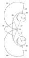
图8是一个示意图,示出了具有根据一个示例性实施例的FS/UWA/ RO表面的图7的静态视域间的影响。 图8中的箭头示出了光传播的方向。FIG. 8 is a schematic diagram illustrating the static viewport effect of FIG. 7 with a FS/UWA/RO surface according to an exemplary embodiment. The arrows in Figure 8 show the direction of light propagation.
图9是一个光线图,示出了根据一个示例性的实施例,从一个显示装置上给定的像素当其反射到眼睛的光线路径。Figure 9 is a ray diagram illustrating the path of light rays from a given pixel on a display device as it reflects to the eye, according to an exemplary embodiment.
图10是一个光线图,示出了根据一个示例性的实施例,从显示装置上的两个像素上当其反射到眼睛的光线路径。Figure 10 is a ray diagram illustrating the path of light from two pixels on a display device as it reflects to the eye, according to an exemplary embodiment.
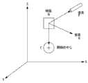
图11是一个示意图,示出了根据一个示例性实施例,用于选择反射器局部法线方向的变量。FIG. 11 is a schematic diagram illustrating variables used to select a reflector local normal direction according to an exemplary embodiment.
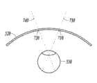
图12代表根据一个示例性实施例,沿着光线路径的弯曲的反射器。Figure 12 represents a curved reflector along the light path according to an exemplary embodiment.
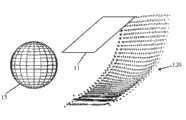
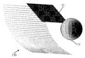
图13和图14从两个方向示出了根据一个示例性实施例的一个FS/UWA/RO表面。Figures 13 and 14 show a FS/UWA/RO surface according to an exemplary embodiment from two directions.
图15和图16从两个方向示出了根据一个示例性实施例的另一个FS/UWA/RO表面。Figures 15 and 16 show another FS/UWA/RO surface according to an exemplary embodiment from two directions.
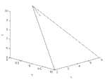
图17是一个示意图,示出了根据一个示例性实施例,用于计算对一个反射表面的局部法线的几何形状。Figure 17 is a schematic diagram illustrating the geometry used to compute a local normal to a reflective surface, according to an exemplary embodiment.
具体实施方式Detailed ways
图2和图3分别示出了由一个使用者105佩戴的头戴式显示装置100侧视图和主视图。头戴式显示设备采用一个FS/UWA/RO表面120。2 and 3 respectively show a side view and a front view of the head mounted
在一个实施例中,头戴式显示装置100可以是,例如,一个光学透视式装置,增强现实装置,双目观测装置。因为光学透视式装置,增强现实装置,双目观测装置通常是一个HMD最复杂的表现形式,本申请将主要讨论这种类型的实施例,可被理解的是,本文所讨论的原则同样适用于光学透视式装置,增强现实装置,单目观测装置,视讯式透视装置,增强现实装置,双目和单目观测装置,以及双目和单目“虚拟现实”系统。In one embodiment, the head-mounted
如图2和3所示,头戴式显示装置100包括一个框体结构107,用于由使用者佩戴,并由使用者的鼻子和耳朵以类似戴眼镜的方式支承。在图2-3的实施例中,以及在本文所公开的其它的实施例中,头戴式显示装置可以具有各种配置,可以,例如,类似于传统的护目镜,眼镜,头盔等。在一些实施方式中,吊带可以被用来保持在HMD框体结构在一个相对于使用者眼睛的固定位置。总体而言,关于HMD的显示装置和使用者眼睛,在HMD包的外表面,可以假定任何保持光学系统在所需方向的任何形式As shown in FIGS. 2 and 3 , the head-mounted
该头戴式显示装置100包括至少一个图像显示系统110和至少一个光学系统,其中该光学系统包括一个反射光表面,如图2和3所示,该反射光表面是自由空间,超广角,反射光表面120,即FS/UWA/ RO表面120,这必然是弯曲的。在一些实施例中,FS/ UWA/ RO表面可以是整个光学系统。表面120可以具有纯粹的反射性能,或可以同时具有反射和透射性能,在这种情况下,它可以被认为是作为一种类型的“分束器”。The head-mounted
FS/UWA/RO表面120可完全包围一只或两只眼睛,以及至少一个图像显示系统110。特别是,表面可以围着眼睛弯曲,并朝向面部侧面,以扩大可用的水平视域。在一个实施例中,FS/UWA/RO表面120可延伸至180°或更大(例如,200°以上),如下文述及的图6中所示。 如图3所示,HMD可以包括两个分开的用于使用者的两只眼睛的FS/UWA/RO表面120R和120L,该FS/UWA/RO表面120R和120L分别得到的框体结构和/或鼻脊片210支承(见下文)。可选的,HMD可以采用一个单一的FS/ UWA RO表面提供双眼一个单一结构,其中的一些部分被双眼共同观看,而其他部分只有一只眼睛观看。The FS/UWA/
正如上文所述并如图3所示,头戴式显示装置100可以包括一个鼻脊片210。鼻脊片可以是一个使两个FS/ UWA/ RO表面之间分离的垂直条或壁,每个FS/ UWA/ RO分别用于使用者的一只眼睛。鼻脊片210也可以使使用者的两只眼睛的视域之间分离。这样,可以通过一个第一图像显示装置和一个第一FS/ UWA/ RO表面将第一图像显示到使用者的右眼,从而使使用者的右眼看到一个三维物理现实环境的第一表示,而可以通过一个第二图像显示装置和一个第二FS/ UWA/ RO表面将第二图像显示到使用者的左眼,从而使使用者的左眼看到一个三维物理现实环境的第二表示。因此,通过每只眼睛看到其相对于三维物理现实环境中位置的正确的图像,一个单独的显示装置/反射面的组合起到了服务使用者的眼睛的作用。通过分离使用者的双眼,脊片210使每个眼睛看到的图像优化独立于另一只眼睛。在一个实施例中,鼻脊片的垂直壁可包括两个反射器,每侧各一个,以允许当使用者护鼻地转动他/她的眼睛时,向左或向右时,能看到图像。As described above and shown in FIG. 3 , the head mounted
至少一个所述图像显示系统110可以安装在FS/UWA/RO的表面120内,可以以水平或以相对于地平线微小的角度布置。可选择的,至少一个所述图像显示系统刚好位于所述FS/UWA/RO的表面的外部。至少一个所述图像显示系统110的倾斜或角度,或更具体的,它的至少一个发光面的倾斜角度,通常是一种像素,图像和/或从表面120反射的显示信息的位置的功能。At least one of said
在某些实施例中,头戴式显示装置100设置为创建一个内部空腔,所述FS/ UWA/ RO表面朝空腔内侧反射。对于具有透射特性的FS/UWA/RO表面,从至少一个图像显示装置发出的图像或显示信息反射到所述空腔并从表面进入使用者的眼睛,并且同时从外部世界的光也通过穿过反射表面进入空腔和使用者的眼睛。In some embodiments, the head-mounted
如下文所详细论述的,在某些实施例中,至少一个所述图像显示系统110提供显示信息的图像和/或片段,所述显示信息的图像和/或片段在进入使用者的眼睛(次)之前被调整为近距视域。在一些实施例中,一个可选的透镜或透镜系统115可以用于调节。共同转让且同时待审的美国专利申请No.13/211,365,以G. Harrison, D. Smith和G. Wiese的名义同时提交的,题为“使用一个或多个菲涅耳透镜的头戴式显示装置”,并标注有代理人案号IS-00307,其内容在此引入本文作为参考,其描述了用于此目的而使用一个或多个菲涅耳透镜。其它实施例中不使用可选的透镜或透镜系统,而是依赖FS/UWA/RO表面以提供由显示系统所形成图像,焦距内,近眼视域所需的光学性质。As discussed in detail below, in some embodiments at least one of the
头戴式显示装置可以包括一个电子封装件140以控制由至少一个所述图像显示系统110所显示的图像。在一个实施例中,电子封装件140包括加速度计和陀螺仪,以同步来自至少一个所述图像显示投影系统110的图片与使用者活动所需的定位,方向和位置信息。可以通过连接到电子封装件140的传输电缆150或无线介质,提供到和来自头戴式显示装置100的电力和视频的传输。The head-mounted display device may include an electronic package 140 to control images displayed by at least one of the
一组相机170可以设于头戴式显示装置100的相对侧上,向电子封装件提供输入,以帮助控制计算机生成,例如,“增强现实”的场面。一组相机170与电子封装件140连接以接收电源和控制信号,并向电子封装件的软件提供视频输入。A set of
头戴式显示装置中使用的图像显示系统可以有许多形式,现在已知的或即将开发的。例如,可以采用小高分辨率的液晶显示器(LCD),发光二极管(LED)显示器,和/或有机发光二极管(OLED)显示器,包括柔性OLED屏幕。特别是,图像显示系统,可以采用一个高清晰度,小外形规格的显示装置,具有高像素密度,可在手机行业中发现其实例。一个光纤束也可以用在图像显示系统中。在各种实施方式中,图像显示系统可以被认为是作为一个小屏幕电视。如果图像显示系统产生偏振光(例如,在图象显示系统采用了液晶,所有的颜色在同样的方向上均为线偏振的情况下),并且如果FS/UWA/RO表面与由显示器发射的光正交偏振,那么光不会从FS/UWA/RO表面泄露出去。这样显示的信息和光源本身在HMD以外是不可见的。Image display systems used in head-mounted display devices can come in many forms, now known or soon to be developed. For example, small high-resolution liquid crystal displays (LCD), light emitting diode (LED) displays, and/or organic light emitting diode (OLED) displays, including flexible OLED screens, may be employed. In particular, image display systems can employ a high definition, small form factor display device with high pixel density, examples of which can be found in the mobile phone industry. A fiber optic bundle can also be used in the image display system. In various implementations, the image display system can be thought of as a small screen television. If the image display system produces polarized light (for example, in the case of image display systems using liquid crystals, all colors are linearly polarized in the same direction), and if the FS/UWA/RO surface is compatible with the light emitted by the display Orthogonal polarization, then light will not leak out from the FS/UWA/RO surface. The information thus displayed and the light source itself are invisible outside the HMD.
根据本申请在构成的光学系统的示例性实施例的整体操作,特别是,用于“扩增实境”HMD的光学系统,由图2的光线路径示出,特别是光线180,185和190。在本实施例中,FS/UWA/RO表面120同时具有反射性和透射性。利用表面120的透射性,光线190从环境中穿过表面并进入向使用者的眼睛。从表面120的相同区域,光线180,由表面反射(利用表面的反射性)并加入光线190从而生成混合光线185,当使用者看着点195的方向,即,当使用者的注视方向在点195的方向时,所述光线185能够光线光线进入使用者的眼睛。当这样看时,使用者的周边视觉功能允许使用者看到从环境中其他点穿过表面120的光线,再次使用到了表面透射特性。The overall operation of an exemplary embodiment of an optical system constructed in accordance with the present application, in particular, an optical system for an "augmented reality" HMD, is illustrated by the ray paths of FIG. 2, particularly rays 180, 185 and 190 . In this embodiment, the FS/UWA/
图4是进一步的光线路径图,示出了本申请所公开的头戴式显示装置100的操作的示例性实施例。在本实施例中,整体的视觉系统包括三个部分:(1)至少一个图像显示系统110,(2)FS/UWA RO表面120,和(3)使用者的眼睛310。表示了一个具有一个内部透镜330的眼睛310。如图2所示,从至少一个所述图像显示系统110的像素发射的光由光线180表示。在由表面120反射后,该光将出现在使用者视网膜的一个点上,提供使用者注视的方向,相关视域,(参阅图7和8下文中的论述)包括光线180撞击表面120的点。更具体的,如下文所述,由于光学性质涉及到,平分从FS/ UWA/ RO表面上的点到眼睛和到像素的矢量的法线,像素将只出现在点195处;即,即使从像素发出的光在更广泛的圆锥范围内辐射,FS/UWA/RO表面设计为只让光线从一个位置进入。FIG. 4 is a further light path diagram illustrating an exemplary embodiment of the operation of the head-mounted
在图4中,假定使用者的注视方向是朝向光线180与表面120的交叉点,如光线185和340所示。然而眼睛看到的,是一个出现在它前面的空间中离眼睛一段距离的虚拟的图像,该段距离由矢量345和350表示,例如,由参考数字352表示在无穷远的距离。在图如图4所示,一把用于说明目的的椅子,由至少一个所述图像显示系统110产生的椅子的实像355,所述实像355在从显示系统发射的光经由FS/ UWA/ RO表面120反射后成为虚拟图像360。在“增强现实”的环境中,光学系统,包括FS/UWA/RO 表面,可以导致,如椅子的虚拟图像360出现在当人365实际所处的物理环境,相同的位置。需要注意的是345线,停在比无穷远近的距离,包含在图4中,以显示该图像,可以光学地出现在附近和无穷大之间的任何距离。例如,人可以站在50米之遥,而那就是放椅子的位置。In FIG. 4 , it is assumed that the gaze direction of the user is toward the intersection of
如图1-4中所示,至少一个所述图像显示系统具有平面发光表面(例如,图4中的表面111)。显示系统也可以具有弯曲的发光表面。这样的实施例示于图5中,光线405由弯曲的显示屏幕407(弯曲的发光表面)发出。此光线由FS/ UWA/ RO表面120反射,并进入使用者的眼睛310的瞳孔415(见光线410)。在本实施例中,表面120也允许由光线345表示的来自外部环境的光,从而使显示生成的图像叠加外部图像。需要注意的是,为了实现图示的目的,光线345偏离光线410;为了实现纯粹外部图像的叠加,光线345将覆盖光线410。As shown in Figures 1-4, at least one of the image display systems has a planar light emitting surface (eg,
如上所述,HMD中使用的以往的光学系统,采用反射光表面的瞳孔成形,从而限制了视域,一个典型的视域为大约60度或更小。这极大地限制了以往的头戴式显示装置的价值和能力。与具有更小视域的HMD相比,在各种实施方式中,本发明所公开的头戴式显示器的视域(FOV)具有更广泛的视域,从而允许多得多的光信息提供给使用者的头戴式显示装置。宽视域可以是大于100°,大于150°或大于200°。除了提供更多信息,通过更好地匹配显示的图像到物理现实中,宽阔的视域使附加信息可以由使用者以更自然的方式进行处理,能够更好地浸入式和增强的现实体验。As noted above, previous optical systems used in HMDs employ pupil shaping of reflective light surfaces, thereby limiting the field of view, a typical field of view being approximately 60 degrees or less. This greatly limits the value and capabilities of previous head-mounted display devices. In various embodiments, the field of view (FOV) of the disclosed head-mounted displays has a wider field of view (FOV) than HMDs with smaller fields of view, allowing much more light information to be provided to the user. head-mounted display device. The wide field of view may be greater than 100°, greater than 150° or greater than 200°. In addition to providing more information, by better matching the displayed image to physical reality, the wide field of view enables additional information to be processed by the user in a more natural way, enabling better immersive and augmented reality experiences.
特别的,在图6示出的该示例性实施例中,对于向前的注视方向,通过弯曲的FS/UWA/RO的表面201和202,使眼睛能够看到图6中表示的整个视觉区域,相应的每只眼睛水平视域(FOV)达到至少150度(例如,大约168度水平视域)。此视域由眼睛视网膜中央凹的视域和它的外围视域组成。此外,眼睛可以自由地绕其转动中心移动以在不同注视方向上准直合并的视网膜中央凹的视域+外围视域,就像眼睛在自然地观察物理世界时所做的那样。本文所公开的光学系统,使眼睛通过一系列如眼睛在观察自然世界时的动作获得信息。In particular, in this exemplary embodiment shown in FIG. 6, for a forward gaze direction, the eyes are enabled to see the entire visual field represented in FIG. 6 by
更详细地观察图6,这张图片是以简化的线条来表示从顶部向下看所看到的使用者的头200的前部。示出了FS/UWA/RO表面201和202设置在使用者眼睛203和204的前面。如上所述,FS/UWA/RO表面201和202可靠在使用者鼻子205,即在使用者的头部200的中央前方214。如下面详细讨论的,表面201和202的局部法线和局部空间位置被调整,以使由至少一个图像显示系统(图6中未示出)产生的图像覆盖每只眼睛的水平视域至少100°,例如,在某些实施例中,至少150℃,在其它实施例中,至少为200°。(可选地,也可以根据下面的讨论,局部的曲率半径也被调整以在与菲涅耳透镜系统结合时提供远距离的虚拟映像。)例如,局部法线和局部空间的位置可以调整,以覆盖使用者完整的大约168度,向前,水平,每只眼睛的静态视域,和从边缘到边缘的FS/UWA/RO表面201或202延伸的168度,由所示的视线210,211和212,213所示。因此,对应于宽静态视域(视网膜中央凹的视域+外围视域)的视线提供给使用者。此外,当继续看计算机生成图像时,使用者可以在转动中心215和216自由转动他的/她的眼睛。Looking at Fig. 6 in more detail, this picture is a simplified line representation of the front of the user's
在图6,以及在图4,图5和12中,为了便于表述,FS/UWA/RO表面作为球体的部分示出。在实践中,表面不是球形,而是具有更复杂的配置,使它们的局部法线和局部空间的位置(和可选的,局部曲率半径)提供所需的静态和动态的视域(和可选的,到虚拟图像所需的距离)。同样,如图6所示,右侧的头戴式显示装置与左侧的操作相同,可被理解的是,如果需要用于特定应用的话,两边可以不同。In Fig. 6, as well as in Figs. 4, 5 and 12, the FS/UWA/RO surface is shown as part of a sphere for ease of presentation. In practice, surfaces are not spherical, but have more complex configurations such that their local normals and local space positions (and, optionally, local radii of curvature) provide the desired static and dynamic viewsheds (and can optional, the desired distance to the virtual image). Also, as shown in Figure 6, the right side of the HMD operates the same as the left side, it being understood that the two sides can be different if desired for a particular application.
图7和图8进一步说明了由本文公开的FS/UWA/RO表面所提供的静态和动态的视域。图7显示了使用者具有注视方向73向前的标称右眼71。眼的视网膜中央凹的视域+外围视域,通过电弧75示出,其中有一个为大约168°的角度范围。需注意,为了便于表述,在图6-8中,相对于使用者眼睛的转动中心,示出视域,而不是使用者的瞳孔的中心或边缘。事实上,人眼所实现的大视域(例如,大约168°),是视网膜大角度范围的结果,允许高度的斜光进入使用者瞳孔到达视网膜的。7 and 8 further illustrate the static and dynamic fields of view provided by the FS/UWA/RO surfaces disclosed herein. Figure 7 shows a user with a nominal right eye 71 with a
图8示意性地示出了图7视域的相互作用,HMD具有:(a)一种图像显示系统,所述图像显示系统的至少一个发光表面81具有一个第一发光区域82(示出为一个正方形)和第二发光区域83(示出为一个三角形)及(b)一个FS/UWA/RO表面,具有第一反射区域84和第二反射区域86,其中所述第一反射区域84有一个第一局部法线85所述第二反射区域86有一个第二局部法线87。Fig. 8 schematically shows the interaction of the field of view in Fig. 7, the HMD has: (a) an image display system, at least one light-emitting surface 81 of the image display system has a first light-emitting area 82 (shown as a square) and second light emitting area 83 (shown as a triangle) and (b) a FS/UWA/RO surface with a first reflective area 84 and a second reflective area 86, wherein the first reflective area 84 has A first local normal 85 and the second reflective region 86 have a second local normal 87 .
如上面所指出中,FS/UWA/RO表面是一个“自由空间”表面和“超广角”表面。此外,如上文所述,并在下面将更详细论述的,表面可以参与到(或是唯一来源)进入使用者的眼睛的光的准直(或部分准直)。这样的准直会导致FS/UWA/RO表面所产生的虚拟图像与使用者相距较远,例如,30米或更长,这允许使用者使用放松的眼睛容易地集中在一个虚拟图像上。As noted above, the FS/UWA/RO surface is a "free space" surface and an "ultra wide angle" surface. Furthermore, as noted above, and discussed in more detail below, the surface may participate in (or be the only source of) collimation (or partial collimation) of light entering the user's eye. Such collimation results in virtual images generated by the FS/UWA/RO surface being far away from the user, eg, 30 meters or more, which allows the user to easily focus on one virtual image with relaxed eyes.
FS/UWA/RO表面的“自由空间”和“超广角”方面可以通过调整表面的局部法线实现,使得使用者的眼睛看到至少一个图像显示系统的发光区域,作为来自FS/UWA/RO表面的预定区域(表面上的预定位置)。The "free-space" and "ultra-wide-angle" aspects of FS/UWA/RO surfaces can be achieved by adjusting the local normals of the surface so that the user's eyes see at least one luminescent region of the image display system, as from FS/UWA/RO A predetermined area of a surface (a predetermined location on a surface).
例如,在图8中,HMD的设计者可能决定,当使用者的注视方向向前时,正方形的虚拟图像88被使用者视网膜中心部分观察是有利的,以及当使用者的注视方向是,例如,向左前方大约50°时,三角形的虚拟图像89被使用者视网膜中心部分观察是有利的。设计者随后会配置至少一个图像显示系统,FS/UWA/RO表面,和任何其它光学系统的组件(例如,一个或多个图像显示系统和FS/UWA/RO表面之间的菲涅耳透镜),这样在使用HMD过程中,正方形的虚拟图像,将会是向前的,而三角形的虚拟图像,将是向左前50°。For example, in FIG. 8, the designer of the HMD may decide that it is advantageous for the square virtual image 88 to be viewed by the central portion of the user's retina when the user's gaze direction is forward, and when the user's gaze direction is, for example, , about 50° to the left front, it is advantageous for the triangular virtual image 89 to be observed by the central portion of the user's retina. The designer will then configure at least one image display system, the FS/UWA/RO surface, and any other optical system components (e.g., Fresnel lenses between one or more image display systems and the FS/UWA/RO surface) , so that in the process of using the HMD, the square virtual image will be forward, and the triangular virtual image will be forward 50° to the left.
以这种方式,当使用者的注视方向(瞄准线)相交在FS/UWA/RO表面直线上,正方形世界的虚拟图像将会是按照需求,在使用者眼睛的中心是可见的,当使用者的注视方向(瞄准线)相交在FS/UWA/RO表面在向左前50度,三角形的虚拟图像同样按照需求,在使用者眼睛的中心将是可见的。虽然图7和8中未示出,相同的方法也可用于垂直视域,以及用于偏轴的视域。更常见的是,在设计HMD和其光学组件,设计者“设置”显示装置的至少一个发光表面,这样当眼睛的注视方向是在特定的方向时,所需的显示装置的部分对使用者的眼睛来说是可视的。因此,当人眼扫视整个视域时,水平方向和垂直方向上,FS/UWA/RO表面照射所述图像显示系统至少一个发光表面的不同部分,进入使用者的眼睛。虽然前面的讨论已经按照标称的使用者视网膜中心,在设计过程中,当然,如果需要的话,替换使用标称使用者视网膜的中央凹的位置。In this way, when the user's gaze direction (line of sight) intersects on the FS/UWA/RO surface line, the virtual image of the square world will be visible in the center of the user's eye as required, when the user The gaze direction (line of sight) intersects the FS/UWA/RO surface at 50 degrees forward to the left, and a triangular virtual image will be visible at the center of the user's eye, also as required. Although not shown in Figures 7 and 8, the same approach can also be used for vertical fields of view, as well as for off-axis fields of view. More commonly, when designing an HMD and its optical components, designers "set up" at least one of the display's light-emitting surfaces so that when the eye's gaze direction is in a particular direction, the desired portion of the display is visible to the user. visible to the eye. Therefore, when human eyes scan the entire field of view, in the horizontal and vertical directions, the FS/UWA/RO surface illuminates different parts of the at least one light emitting surface of the image display system and enters the user's eyes. Although the previous discussion has been in terms of the nominal center of the user's retina, during the design process, of course, the position of the fovea of the user's retina is substituted if desired.
应该指出的是,在图8中,使用者的眼睛任何往右的旋转会引起三角形的虚拟图像89不再对使用者可见。因此,在图8中,任何注视方向,向前或向左前,为使用者提供了正方形和三角形的虚拟图像,而注视方向的向右前只提供一个正方形的虚拟图像。虚拟图像的视力,当然,依赖于虚拟的图像是否使用者的视网膜中央凹视力或周围边缘视觉感受到。It should be noted that in Figure 8, any rotation of the user's eye to the right would cause the triangular virtual image 89 to no longer be visible to the user. Thus, in Figure 8, any gaze direction, forward or left, provides the user with square and triangular virtual images, while a gaze direction forward to the right provides only a square virtual image. The visual acuity of the virtual image, of course, depends on whether the virtual image is perceived by the user's foveal vision or peripheral vision.
如果HMD的设计者将正方形的虚拟图像放置在图8中偏右的位置,而将三角形的虚拟图像放置在图8中偏左的位置,将存在只能看到正方形的虚拟图像的注视方向和只有三角形的虚拟图像可见的其它注视方向。同样地,在本文所公开原则的基础上,设计者可以设置正方形的虚拟图像和三角形的虚拟图像,使三角形的虚拟图像总是可见的,而在某些注视方向上,正方形的虚拟图像是可见的,但其他方向不可见。作为进一步的变化,HMD的设计者可以将正方形的虚拟图像和三角形的虚拟图像放置在一个或多个注视方向上,而图像对使用者是不可见的,例如,设计者可以在向前的注视方向上,将虚拟图像放置在使用者静态视域之外。由本公开向HMD设计者所提供的灵活性,因此,显而易见。If the designer of the HMD places the square virtual image on the right side of Figure 8, and the triangle virtual image on the left side of Figure 8, there will be gaze directions where only the square virtual image can be seen and Other gaze directions visible only to the virtual image of the triangle. Similarly, on the basis of the principles disclosed in this paper, the designer can set the virtual image of the square and the virtual image of the triangle so that the virtual image of the triangle is always visible, while the virtual image of the square is visible in certain gaze directions. , but not visible in other directions. As a further variation, the designer of the HMD can place a square virtual image and a triangular virtual image in one or more gaze directions, while the images are invisible to the user, for example, the designer can place the virtual image in the forward gaze Orientation, placing the virtual image outside the user's static field of view. The flexibility afforded to the HMD designer by the present disclosure is, therefore, apparent.
在一个实施例中,所述反射面的“自由空间”和“超广角”的方面通过使用费马原理和英雄根据以使得光沿着最短光学路径(最短时间)实现。共同转让且同时待审的美国专利申请No.13/211,389,以G. Harrison, D.Smith, 和G. Wiese的名义同时提交的,题为“制造自由空间反射光表面的方法和系统”,并标有代理人案号IS-00354,其内容在此引入本文作为参考,其描述了一种实施例,在该实施例中,使用了费马和希罗原则以设计适合在头戴式显示器中使用的FS/UWA/RO表面。In one embodiment, the "free space" and "ultra wide angle" aspects of the reflective surface are achieved by using Fermat's principle and the hero's principle such that light follows the shortest optical path (shortest time). Commonly assigned and co-pending U.S. Patent Application No. 13/211,389, filed concurrently in the names of G. Harrison, D. Smith, and G. Wiese, entitled "Method and System for Fabricating Free-Space Reflective Light Surfaces ”, and designated Attorney Docket No. IS-00354, the contents of which are incorporated herein by reference, describe an embodiment in which Fermat and Hero principles are used to design a FS/UWA/RO surfaces used in displays.
通过费马和希罗最少时间原则,所述图像显示系统(例如,任何像素的图像显示系统)至少一个发光表面的任何“希望的部分”,可以使FS/UWA/RO表面的任何所需反射点,提供从至少一个所述发光面的所需部分到FS/UWA/RO表面的反射点的光路,然后在一个极值到使用者眼睛转动中心。By Fermat's and Hero's principle of least time, any "desired part" of at least one light-emitting surface of the image display system (eg, any pixel image display system) can make any desired reflective point of the FS/UWA/RO surface , providing a light path from a desired portion of at least one of said light-emitting surfaces to a reflection point on the FS/UWA/RO surface, and then at an extremum to the center of rotation of the user's eyes.
光路的极值意味着,光路长度的一阶导数已达到零值,表示光路长度的最大值或最小值。极值可以通过创建反射光表面的一个局部区域,其法线平分(a)一个从局部区域到使用者眼睛的向量(例如,从局部区域的中心到使用者眼睛中心的向量),以及(b)一个从局部区域到发光表面“所需的部分的向量(例如,一个从局部区域的中心到发光表面“所需部分”中心的向量)。图9和图10示出了在此情况下的过程,图像显示系统的至少一个发光表面的“所需部分”是像素。An extremum of the optical path means that the first derivative of the optical path length has reached a value of zero, indicating a maximum or minimum value of the optical path length. Extrema can be created by creating a local region of the reflective surface whose normal bisects (a) a vector from the local region to the user's eye (e.g., a vector from the center of the local region to the center of the user's eye), and (b ) a vector from the local area to the "desired part" of the light-emitting surface (for example, a vector from the center of the local area to the center of the "desired part" of the light-emitting surface). Figures 9 and 10 show the process, the "required portion" of at least one light-emitting surface of an image display system is a pixel.
具体而言,图9示出了由大致矩形的像素阵列组成的图像显示系统的发光表面510,朝头戴式显示装置光束515方向的前面发光。光束515从反色光表面520反射回来,为了便于表述,图8中作为平面表示。经反射,光束515变为进入使用者的眼球530的光束525。Specifically, FIG. 9 shows a light-emitting
为了确定用于每一个像素的反射表面的法线的目的,只需要对应光束515和525来确定三维向量的平分线。如图9所示,该平分线向量以二维形式显示为线535。平分线向量535在反射点540垂直于光学表面,表面520上的位置,即发光面510的像素545对于HMD使用者将是可见的。For the purpose of determining the normal to the reflective surface for each pixel, only the bisectors of the three-dimensional vectors need be determined for the corresponding
具体而言,在操作中,在显示表面510的像素545发射的光束515,在反射光表面520以一角度反弹,所述角度由对应于平分矢量535及其垂直平面550的表面法线所确立,通过费马和希罗原则产生,在反射点540的反射像素,沿光束525被眼530看到。Specifically, in operation,
为了准确计算在反射点540的表面法线,光束525大约穿过使用者眼睛的中心530。结果大体保持稳定,即使使用者的眼球转动,成为周边视力,如上所述以及图7和图8所示,眼睛转动得过多,以至于显示装置的那个区域不能被使用者眼睛中心凹的视力或周边视力看到。In order to accurately calculate the surface normal at the
为了计算表面法线的位置,可以采用四元数的方法,其中In order to calculate the position of the surface normal, the quaternion method can be used, where
ql =光束515的方向ql = direction of
q2 =光束525的方向q2 = direction of
和and
q3 =所要求的表面发现535的方向=(ql + q2)/2q3 = direction of the requested surface to find 535 = (ql + q2)/2
表面法线也可以描述为向量表示法,如图11所示。在下面的公式和图11中,点N是一个远离位于根据需要的反射光表面的区域中心中的点M的单位,并且在这样的方向上,即M点上的反射光表面的切面的垂直法线的方向上。在点M的反射光表面的切面被控制以满足下面的公式表示的关系,从而在三维空间中,使得M点的表面法线平分从M点到根据需要的像素中心P点的线,以及从M点到使用者眼睛转动中心C点的线。(仅供参考,点C是从眼睛前面向后大约13毫米,):Surface normals can also be described as vector notation, as shown in Figure 11. In the formula below and in Figure 11, point N is one unit away from point M located in the center of the region of the reflective light surface as desired, and in such a direction that the tangential plane of the reflective light surface at point M is perpendicular to in the direction of the normal. The tangent plane of the reflected light surface at point M is controlled to satisfy the relationship expressed by the following formula, so that in three-dimensional space, the surface normal of point M bisects the line from point M to the pixel center point P as required, and from The line from point M to point C, the center of rotation of the user's eyes. (FYI, point C is about 13 mm back from the front of the eye,):

其中所有的点,N,M,P,和C有[x, y, z]组成,表示在任意的三维空间的笛卡尔坐标系统中的位置。All points, N, M, P, and C are composed of [x, y, z], which represent the position in the Cartesian coordinate system of any three-dimensional space.
所得的法线向量N-M具有欧几里德长度The resulting normal vector N-M has Euclidean length
两条竖线表示的欧几里德长度,按下列公式计算的:The Euclidean length represented by the two vertical lines is calculated according to the following formula:

作为算例,考虑以下的M,P,和C值:As an example, consider the following values of M, P, and C:


图17中所示出的的几何形状,平分线在两个长矢量之间。For the geometry shown in Figure 17, the bisector is between two long vectors.
以上所述当然仅仅是一种代表性的显示使用最小时间的费马和希罗原则的计算,以确定局部切平面角,局部切平面角约束反射区域的自由空间(自由形式)表面歧管,表面歧管由反射区域中的点组成。意在呈现给观察者一个连续的虚拟图象。唯一的实常数是使用者眼睛的中心,以及眼睛的自然视域。所有其他组件可以被迭代地更新,直至形成适当的解决方案,用于一个给定的图象显示系统和得到反射光表面取向。另一种方式,像素的图像反射位置,M1,M2,... ,Mn及其相关的法线和曲率可以被认为是“翘曲”的矩阵(调整),使FS/UWA/RO的表面达到通过图像显示系统形成计算机生成图像的所需虚拟图像。The above is of course only a representative representation showing the use of minimum time Fermat and Hero principles for calculations to determine the local tangent plane angle, the local tangent plane angle constraining the reflective region of the free-space (free-form) surface manifold, the surface The manifold consists of points in the reflection area. It is intended to present a continuous virtual image to the viewer. The only real constants are the center of the user's eye, and the eye's natural field of view. All other components can be iteratively updated until an appropriate solution is developed for a given image display system and reflective light surface orientation. Another way, the image reflection positions of pixels, M1, M2, ... , Mn and their associated normals and curvatures can be thought of as "warping" matrices (adjustments) such that the surface of FS/UWA/RO Achieving the desired virtual image by forming a computer-generated image through an image display system.
在应用费马和希罗原则时,应当指出,在一些实施例中,需要避免这样的情形,即调整法线,使使用者在超过一个点上看到相同的像素反射。还应当指出,在一些实施例中,反射光表面的局部区域可以是非常小的,甚至可能对应于反射装置上的一个点,点变成其他点,以产生光滑的表面。In applying the Fermat and Hero principles, it should be noted that in some embodiments it is necessary to avoid situations where normals are adjusted such that the user sees the same pixel reflection at more than one point. It should also be noted that in some embodiments the localized area of the reflective light surface may be very small, and may even correspond to a point on the reflective means, which changes into other points to produce a smooth surface.
为了确保使用者能够容易地集中于至少一个发光面(例如,一个像素点的虚拟图像)的“所需部分”的虚拟图像曲率半径,控制反射点(反射区域)周围区域的反射点的曲率半径,使得一个准直(或接近准直的)的图像到达使用者。准直后的图像(或接近准直的)图像具有更多的并行的光学光线,好像图像产生于使用者的一个远的距离,例如几十到几百米。为了实现这样的表面,对应于至少一个发光面(所需的发光像素)“所需部分”的,反射光表面的反射区域的曲率半径,可以保持半径接近从反射区域到显示装置上发光表面(真实像素)的真实“所需部分”的一半距离。In order to ensure that the user can easily focus on the radius of curvature of the virtual image of the "desired part" of at least one light-emitting surface (for example, a virtual image of one pixel point), the radius of curvature of the reflection point in the area around the reflection point (reflection area) is controlled , so that a collimated (or nearly collimated) image reaches the user. A collimated (or nearly collimated) image has more parallel optical rays, as if the image was generated at a great distance from the user, eg tens to hundreds of meters. To achieve such a surface, the radius of curvature of the reflective area of the light-reflecting surface, corresponding to the "required portion" of at least one light-emitting surface (desired light-emitting pixel), can be kept close to the radius from the reflective area to the light-emitting surface on the display device ( half the distance of the real "desired part" of the real pixel).
因此,在一个实施例中,内反射像素从有关像素到相邻像素的法线向量满足关系式,使他们能够建立的曲率半径,大约是一半的反射表面上反射像素位置到显示像素向量长度。影响这个参数的调整包括所述的至少一个发光面的尺寸大小,以及是否所述的至少一个发光表面是弯曲的。Thus, in one embodiment, the normal vectors of internally reflected pixels from the relevant pixel to adjacent pixels satisfy a relationship that enables them to establish a radius of curvature that is approximately half the length of the vector from the position of the reflected pixel on the reflective surface to the displayed pixel. Adjustments affecting this parameter include the size of the at least one light-emitting surface, and whether the at least one light-emitting surface is curved.
图10示出了这个实施例。为了控制像素区域周围的曲率半径,使准直的(或接近准直的)的图像达到使用者,考虑到了两个相邻的像素的反射区域,如在反射点540。更多的区域可以认为是更好的平衡,但两个是足够的。参照图10,两个像素的反射点540和610,相对于两个像素545和615显示,分别显示在显示表面510。表面法线在点540和610沿着它们方向之间的角度进行计算。知道点540和610之间的角度和距离计算曲率半径。具体而言,表面设置,如果需要的话,调整表面的空间位置直到曲率半径等于(或约等于)光束515和620的平均长度的一半。以这种方式,零或接近零的屈光度光可以被提供给使用者眼睛。这相当于来自基本上无限远处的点的光,光的波阵面是平的,导致平行的表面法线到达光的波阵面。Figure 10 shows this embodiment. In order to control the radius of curvature around the pixel area so that a collimated (or nearly collimated) image reaches the user, the reflective areas of two adjacent pixels are taken into account, such as at
除了控制局部的曲率半径,在某些实施例中,作为第一顺序的点解决方案,具有准直的(或接近准直的)图像进入眼内,至少一个所述发光表面,是标称地位于一个焦距的距离,远离FS/UWA/RO表面,其中的焦距是基于组成FS/UWA/RO表面的各反射区域的曲率半径的平均值。In addition to controlling the local radius of curvature, in some embodiments, as a first order of point resolution, with a collimated (or nearly collimated) image entering the eye, at least one of said emitting surfaces, is nominally Located at a distance of one focal length away from the FS/UWA/RO surface, where the focal length is based on the average of the radii of curvature of the reflective regions making up the FS/UWA/RO surface.
应用费马和希罗原则的结果是一组反射区域,可以组合成光滑的反射面的。在一般情况下,该表面将不是球形的或对称的。图12是一个这样的FS/UWA/RO表面520的二维表示。如上所述,表面520可以这样构成,点710和720的曲率半径设置为提供图像放松地观察,图像来自图像显示系统的至少一个发光表面,并被表面反射。通过这种方式,观察以线730表示的特定方向时,将提供一个准直的(或接近准直的)到眼睛530的虚拟图像,与观察以线740表示的不同方向一样。为了能跨越所有视域获得平滑的传输,FS/UWA/RO表面区域可能会平滑地从一个控制点过渡到另一个,可通过采用非均匀有理B样条(NURBS)技术用于花键表面执行,这样就产生了在整个反射表面的平稳过渡。在某些情况下,FS/UWA/RO表面可包括足够数量的区域,以使表面在细粒级变得光滑。在一些实施例中,对显示的每个部分(如每个像素)所使用的不同放大倍率可能会提供使用一个渐进的梯度,以使得更好的可制造性,实现,和图像质量。The result of applying the Fermat and Hero principles is a set of reflective regions that can be combined into smooth reflective surfaces. In general, the surface will not be spherical or symmetrical. FIG. 12 is a two-dimensional representation of one such FS/UWA/
图13和14示出了从两个不同的角度,使用的上述技术创建的一个FS/UWA/RO表面。图15和16再次从两个方面示出了图13和14的反射面进一步细化的版本, 这些数字的FS/UWA/RO表面通过使用上文提及的共同转让和共同未决,名为“用于创建自由空间反射光表面的方法和系统”的基于计算机的技术设计。Figures 13 and 14 show a FS/UWA/RO surface created using the above technique from two different perspectives. Figures 15 and 16 show further refined versions of the reflective surfaces of Figures 13 and 14 again from two perspectives, the FS/UWA/RO surfaces of these figures are named Computer-based technical design for "Methods and systems for creating free-space reflective light surfaces."
由上可知,可以看出,已经公开了头戴式显示器的设计方法,在示范性实施例中,可以包括:确定所希望的视域,是选择一个显示表面的大小(例如,宽度和高度尺寸),选择的取向的显示表面相对的反射面,目录的显示表面上的每一个像素的位置,并选择一个位置的每一个像素的显示的显示表面上的反射面。显示表面可以放置在眼睛上方,并朝向反射面倾斜,使发射面曲率能够反射光到使用者的眼睛。在进一步的实施例中,显示表面可以被放置在其他位置,如眼睛侧面或眼睛下方的,使选择的反射位置和曲率能够合适地反射来自显示面的光,或倾斜不同的角度。As can be seen from the above, it can be seen that the design method of a head-mounted display has been disclosed. In an exemplary embodiment, it may include: determining a desired viewing area, which is to select a size of a display surface (for example, width and height dimensions ), select the orientation of the display surface relative to the reflective surface, catalog the location of each pixel on the display surface, and select a location for each pixel of the display on the display surface on the reflective surface. The display surface may be placed over the eye and sloped towards the reflective surface such that the curvature of the reflective surface reflects light to the user's eye. In further embodiments, the display surface may be placed in other locations, such as to the side of the eye or below the eye, with the reflective location and curvature chosen to reflect light from the display surface appropriately, or tilted at different angles.
在某些实施例中,一个反射面的三维示例或数学表达式可以被创建,如上文所述,反射表面的每个区域作为一个局部区域具有一个平分从区域的中心到使用者眼睛以及到显示装置表面像素中心的向量的法线。正如上面所讨论的,可以控制像素反射周围区域的曲率半径,以准直的(或接近准直的)图像穿过视域到达使用者。通过基于计算机的迭代,可变参数(例如,局部法线,局部曲率,局部空间位置)可以被调整,直到参数组合(集)确定为能够提供所需的光学性能水平,以及作为一个制造设计是可以审美接受的。In some embodiments, a three-dimensional representation or mathematical representation of a reflective surface can be created, as described above, with each area of the reflective surface as a local area having a bisecting from the center of the area to the user's eyes and to the display The normal of the vector at the pixel center of the device surface. As discussed above, it is possible to control the radius of curvature of the area around which the pixel reflects to produce a collimated (or nearly collimated) image across the field of view to the user. Through computer-based iteration, variable parameters (e.g., local normal, local curvature, local spatial position) can be tuned until a combination (set) of parameters is determined to provide the desired level of optical performance, and as a manufactured design is aesthetically acceptable.
在使用期间,在某些实施例中,非对称的FS/UWA/RO表面,由多个焦点的局部区域的样条曲面构成,形成图像显示系统的至少一个发光表面的虚拟图像,横跨一个宽广的视域。FS/UWA/RO表面可能被认为是一个渐进镜或渐进弯曲光束分离器或一个自由形态的镜子或反射器。由于眼睛从水平和垂直方向上仔细观察室与,弯曲的FS/UWA/RO表面将图像显示系统的至少一个发光表面的各个部分照映到使用者的眼睛中。在不同的实施例中,整个光学系统能够以很低的成本大批量生产同时保证图像的质量与典型的人类目力分辨率相同。During use, in some embodiments, an asymmetric FS/UWA/RO surface, composed of spline surfaces of localized regions of multiple focal points, forms a virtual image of at least one light-emitting surface of the image display system, spanning a Wide field of view. The FS/UWA/RO surface may be considered as a progressive mirror or progressively curved beam splitter or as a free-form mirror or reflector. The curved FS/UWA/RO surfaces reflect portions of the at least one light-emitting surface of the image display system into the user's eyes as the eye scrutinizes the room both horizontally and vertically. In various embodiments, the entire optical system can be mass-produced at low cost while maintaining image quality comparable to typical human eye resolution.
按照HMD的整体结构,表1中列出了根据本申请,所通常满足的具有代表性,并且非限制性的关于HMD显示装置构成参数的例子。此外,本文所公开的HMD显示器通常有一个像素间的距离,该距离足够小,以确保使用者在视觉平面上建立有力的图像。According to the overall structure of the HMD, Table 1 lists typical and non-limiting examples of the configuration parameters of the HMD display device that are generally satisfied according to the present application. Additionally, the HMD displays disclosed herein generally have an inter-pixel distance that is small enough to ensure a robust image is created on the viewing plane by the user.
本文所公开的头戴式显示器可以被包括各种功能,包括但不限于下面的内容,其中一些已被上面提到:The head-mounted displays disclosed herein may include various functions, including but not limited to the following, some of which have been mentioned above:
(1)在一些实施例中,一个或多个菲涅耳透镜可用于调整从显示面发出的光束屈光度特性。(1) In some embodiments, one or more Fresnel lenses can be used to adjust the diopter characteristics of the light beam emitted from the display surface.
(2)在一些实施例中,反射光表面可以是半透明的,允许光线从外部环境进入。内部显示生成的图像可以叠加的外部形象。通过使用定位设备,例如陀螺仪,照相机,和计算机生成图像的软件操作,两幅图像可以匹配结合,以使虚拟图像处于外部环境中的适当位置。特别是,可使用一个摄像头,加速度计,和/或陀螺仪来用于辅助装置的记录,它是在物理现实中,并叠加其图像到外部视图中。在这些实施例中,反射光表面的相对透射率和反射率之间的平衡,可以选择向使用者提供叠加图像附以适当的亮度特性。此外,同样在这些实施例中,现实世界中的图像和计算机生成的图像可以共同出现在大约是相同的表观距离,从而使眼睛能立刻集中在这两个图像。(2) In some embodiments, the light-reflecting surface may be translucent, allowing light to enter from the external environment. The generated image for the internal display can be superimposed on the external image. Using positioning devices such as gyroscopes, cameras, and computer-generated image software manipulation, the two images can be matched and combined so that the virtual image is in place in the external environment. In particular, a camera, accelerometer, and/or gyroscope may be used to assist the device in recording that it is in physical reality and superimposing its image on the external view. In these embodiments, the balance between the relative transmittance and reflectivity of the reflective surface can be selected to provide the user with an overlay image with appropriate brightness characteristics. Furthermore, also in these embodiments, the real-world image and the computer-generated image can co-occur at approximately the same apparent distance, allowing the eye to focus on both images at once.
(3)在一些实施例中,反射光表面保持尽可能地薄,以便最大限度地减少外部光穿过表面对位置或焦点的影响。(3) In some embodiments, the light-reflecting surface is kept as thin as possible in order to minimize the impact of external light passing through the surface on position or focus.
(4)在一些实施例中,头戴式显示装置提供每只眼睛至少100度,至少150度,或至少200度的视域。(4) In some embodiments, the head-mounted display device provides a field of view of at least 100 degrees, at least 150 degrees, or at least 200 degrees for each eye.
(5)在一些实施例中,头戴式显示装置提供给每只眼睛的静态视域不在任何很大的程度上重叠使用者的鼻子。(5) In some embodiments, the static field of view provided to each eye by the head-mounted display device does not overlap the user's nose to any significant extent.
(6)在一些实施例中,反射光表面可以采用对其整个光学视域的一个光学处方渐进过渡,以维持可用显示区域上的焦点。(6) In some embodiments, the reflective light surface may employ an optical prescription gradual transition over its entire optical field of view to maintain focus on the available display area.
(7)在一些实施例中,光线路径可被用于装置的自定义参数,用于特定的实施,如军事训练,飞行模拟,游戏和其他商业应用。(7) In some embodiments, the light path can be used to customize parameters of the device for specific implementations, such as military training, flight simulation, games and other commercial applications.
(8)在一些实施例中,反射光表面和/或显示装置的表面,以及透镜曲率(使用时),以及显示装置和反射光表面之间的距离,反射光表面和眼之间的距离,可以相对于一个调制传递函数(MTF)规范,在视网膜和/或中心凹处操作。(8) In some embodiments, the light reflecting surface and/or the surface of the display device, and the lens curvature (when used), and the distance between the display device and the light reflecting surface, the distance between the light reflecting surface and the eye, Can operate at the retina and/or the fovea with respect to a modulation transfer function (MTF) specification.
(9)在一些实施例中,本文所公开的HMD可以实现在相关应用,但不限于,例如,狙击检测,商业培训,军事训练和操作,和CAD制造。(9) In some embodiments, the HMD disclosed herein can be implemented in related applications, but not limited to, for example, sniper detection, commercial training, military training and operations, and CAD manufacturing.
一旦设计完毕,本文公开的反射光表面,(例如,FS/UWA/RO表面上)可以生产了,例如,制造的数量,使用现在已知的或其后开发的各种不同的技巧和各种不同材料。例如,表面可以由已被金属化的塑料材料以进行合适的反射。打磨塑料或玻璃材料也可以被使用。为“增强现实”的应用,反射光表面可以由嵌入小反射器的透明材料构成,从而反射入射波前的一部分,同时允许光的传播通过该材料。Once designed, the optically reflective surfaces disclosed herein, (e.g., on FS/UWA/RO surfaces) can be produced, e.g., in manufactured quantities, using various techniques and various techniques now known or later developed. different materials. For example, the surface may consist of a plastic material that has been metallized for suitable reflection. Sanded plastic or glass materials can also be used. For "augmented reality" applications, reflective light surfaces can be constructed of transparent materials embedded with small reflectors, thereby reflecting a portion of the incident wavefront while allowing the propagation of light through the material.
对于原型零件,丙烯酸类塑料(例如,有机玻璃)可能和由金刚石车削形成的部分一起使用。对于生产部件,例如,可以是丙烯酸类或聚碳酸酯可能和,例如,通过注射成型技术形成的部分一起使用。反射光表面可被描述为一个详细的计算机辅助绘图(CAD)描述,或作为非均匀有理B样条曲线NURBS曲面,它可以被转换成CAD描述。具有CAD文件可以使装置通过使用3-D打印制作,CAD描述可以直接产生一个三维对象,而不需要加工。For prototype parts, acrylic plastics (for example, plexiglass) may be used with parts formed by diamond turning. For production parts, for example, acrylic or polycarbonate may be used together with parts formed, for example, by injection molding techniques. A reflective surface can be described as a detailed computer-aided drafting (CAD) description, or as a non-uniform rational B-spline NURBS surface, which can be converted into a CAD description. Having a CAD file allows devices to be fabricated using 3-D printing, and the CAD description can directly produce a three-dimensional object without machining.
上文论述的数学技术可以在现在已知的或随后开发的,不同的编程环境和/或编程语言下编码。当前首选的编程环境是Java语言,运行在Eclipse的编程接口。如果需要的话,也可用于其他的编程环境,例如Microsoft Visual C#中的。计算也可以通过付费点击使用马萨诸塞州,李约瑟销售的Mathcad平台,和/或美国马萨诸塞州Natick郡,Math Works公司的Matlab平台。所得的程序可以存储在一个硬盘驱动器,记忆棒,光盘,或类似的装置。步骤是可从各种各样的厂商,使用典型的桌面计算设备,如DELL,HP,东芝等,可选的,如果需要,可以使用更强大的计算机设备,包括“云”计算。The mathematical techniques discussed above can be coded in different programming environments and/or programming languages, now known or later developed. The current preferred programming environment is the Java language, which runs on the Eclipse programming interface. It can also be used in other programming environments, such as Microsoft Visual C#, if desired. Calculations can also be made via pay-per-click using the Mathcad platform sold by Needham, MA, and/or the Matlab platform sold by Math Works, Inc., Natick County, MA, USA. The resulting program can be stored on a hard drive, memory stick, CD, or similar device. The steps are available from a wide variety of manufacturers, using typical desktop computing equipment such as DELL, HP, Toshiba, etc. Optionally, more powerful computing equipment, including "cloud" computing, can be used if desired.
不脱离本发明的范围和精神下,对本发明各种修改对本技术领域的普通技术人员将是显而易见的。例如,尽管反射光表面,为使用者提供了一个大视域,例如,大于或等于100°,150°,或200°的视域,构成本发明设计方面的一个有益的实施例。用于设计本文所公开的反射光表面的基于计算机的方法和系统也可用于创建具有较小的视域的表面。以下的权利要求意在覆盖这些内容和其它的修改,变化,以及与此处所阐述具体实施例的等同物。Various modifications to this invention will become apparent to those skilled in the art without departing from the scope and spirit of this invention. For example, providing a user with a large field of view, eg, greater than or equal to 100°, 150°, or 200°, despite a reflective surface, constitutes an advantageous embodiment of the design aspect of the present invention. The computer-based methods and systems for designing light-reflecting surfaces disclosed herein can also be used to create surfaces with smaller viewing areas. The following claims are intended to cover these and other modifications, changes, and equivalents to the specific embodiments set forth herein.
表1Table 1

Claims (23)
Applications Claiming Priority (5)
| Application Number | Priority Date | Filing Date | Title |
|---|---|---|---|
| US201061427530P | 2010-12-28 | 2010-12-28 | |
| US61/427,530 | 2010-12-28 | ||
| US13/211,372US8625200B2 (en) | 2010-10-21 | 2011-08-17 | Head-mounted display apparatus employing one or more reflective optical surfaces |
| US13/211,372 | 2011-08-17 | ||
| PCT/IB2011/055820WO2012052979A2 (en) | 2010-10-21 | 2011-12-20 | Head-mounted display apparatus employing one or more reflective optical surfaces |
Publications (1)
| Publication Number | Publication Date |
|---|---|
| CN103261944Atrue CN103261944A (en) | 2013-08-21 |
Family
ID=48964008
Family Applications (1)
| Application Number | Title | Priority Date | Filing Date |
|---|---|---|---|
| CN2011800606603APendingCN103261944A (en) | 2010-12-28 | 2011-12-20 | Head-mounted display devices employing one or more light-reflecting surfaces |
Country Status (2)
| Country | Link |
|---|---|
| KR (1) | KR101928764B1 (en) |
| CN (1) | CN103261944A (en) |
Cited By (14)
| Publication number | Priority date | Publication date | Assignee | Title |
|---|---|---|---|---|
| CN103784298A (en)* | 2013-11-20 | 2014-05-14 | 中国科学院光电技术研究所 | Visual training appearance is corrected to individualized human eye aberration of wear-type |
| WO2015058625A1 (en)* | 2013-10-23 | 2015-04-30 | 卫荣杰 | Head mounted perspective display device |
| CN106842573A (en)* | 2017-01-26 | 2017-06-13 | 西安可视可觉网络科技有限公司 | A kind of AR or VR imaging methods and can be used for the glasses of AR or VR |
| CN106842569A (en)* | 2016-12-30 | 2017-06-13 | 北京七鑫易维信息技术有限公司 | A kind of head-mounted display apparatus and its display methods |
| CN107300769A (en)* | 2013-11-27 | 2017-10-27 | 奇跃公司 | Virtual and augmented reality System and method for |
| CN107797278A (en)* | 2016-09-07 | 2018-03-13 | 美国梦境视觉公司 | Head mounted display |
| CN108427193A (en)* | 2017-02-14 | 2018-08-21 | 深圳梦境视觉智能科技有限公司 | Augmented reality display system |
| CN109661687A (en)* | 2016-08-02 | 2019-04-19 | 奇跃公司 | Fixed distance virtual and augmented reality systems and methods |
| US10359545B2 (en) | 2010-10-21 | 2019-07-23 | Lockheed Martin Corporation | Fresnel lens with reduced draft facet visibility |
| CN110488489A (en)* | 2018-05-15 | 2019-11-22 | 苹果公司 | Eyes for wearing sandwich type element are registered |
| US10495790B2 (en) | 2010-10-21 | 2019-12-03 | Lockheed Martin Corporation | Head-mounted display apparatus employing one or more Fresnel lenses |
| TWI679450B (en)* | 2014-10-17 | 2019-12-11 | 美商洛伊馬汀公司 | Head-mounted ultra wide viewing angle display device |
| WO2020034837A1 (en)* | 2018-08-17 | 2020-02-20 | 杨建明 | Augmented reality glasses |
| US10754156B2 (en) | 2015-10-20 | 2020-08-25 | Lockheed Martin Corporation | Multiple-eye, single-display, ultrawide-field-of-view optical see-through augmented reality system |
Families Citing this family (3)
| Publication number | Priority date | Publication date | Assignee | Title |
|---|---|---|---|---|
| KR20190087061A (en) | 2018-01-16 | 2019-07-24 | 주식회사 씨에스위모 | Head mounted display device for a smart phone |
| WO2020050496A1 (en)* | 2018-09-04 | 2020-03-12 | 주식회사 엠투에스 | Optometric head mounted display device and ophthalmologic examination method using same |
| KR102455306B1 (en) | 2022-05-16 | 2022-10-19 | 주식회사 라훔나노테크 | Apparatus, method, and computer program for providing vision using head mount working with a smartphone |
Citations (9)
| Publication number | Priority date | Publication date | Assignee | Title |
|---|---|---|---|---|
| US4026641A (en)* | 1975-12-30 | 1977-05-31 | The United States Of America As Represented By The Secretary Of The Army | Toric reflector display |
| WO1992016867A1 (en)* | 1991-03-12 | 1992-10-01 | B.V. Optische Industrie 'de Oude Delft' | Helmet mountable display system and helmet provided with such a display system |
| CN1082228A (en)* | 1992-04-21 | 1994-02-16 | 班德加普技术公司 | Vertical-cavity surface-emitting laser array display system |
| CN1391126A (en)* | 2001-06-11 | 2003-01-15 | 伊斯曼柯达公司 | Optical headworn device for stereo display |
| US7119965B1 (en)* | 2003-02-24 | 2006-10-10 | University Of Central Florida Research Foundation, Inc. | Head mounted projection display with a wide field of view |
| US20070091447A1 (en)* | 2005-10-03 | 2007-04-26 | Kazutaka Inoguchi | Image display apparatus |
| CN101038598A (en)* | 2006-03-17 | 2007-09-19 | 清华大学 | Freeform curved surface reflector design system and method thereof |
| US20070236800A1 (en)* | 2006-03-03 | 2007-10-11 | Ozan Cakmakci | Imaging systems for eyeglass-based display devices |
| CN103348278A (en)* | 2010-12-16 | 2013-10-09 | 洛克希德马丁公司 | Collimated display with pixel lens |
Family Cites Families (2)
| Publication number | Priority date | Publication date | Assignee | Title |
|---|---|---|---|---|
| NZ537849A (en)* | 2005-01-21 | 2007-09-28 | Peter James Hilton | Direct Retinal Display projecting a scanned optical beam via diverging and converging reflectors |
| JP2010020065A (en)* | 2008-07-10 | 2010-01-28 | Olympus Corp | Image display apparatus |
- 2011
- 2011-12-20CNCN2011800606603Apatent/CN103261944A/enactivePending
- 2011-12-20KRKR1020137013037Apatent/KR101928764B1/ennot_activeExpired - Fee Related
Patent Citations (9)
| Publication number | Priority date | Publication date | Assignee | Title |
|---|---|---|---|---|
| US4026641A (en)* | 1975-12-30 | 1977-05-31 | The United States Of America As Represented By The Secretary Of The Army | Toric reflector display |
| WO1992016867A1 (en)* | 1991-03-12 | 1992-10-01 | B.V. Optische Industrie 'de Oude Delft' | Helmet mountable display system and helmet provided with such a display system |
| CN1082228A (en)* | 1992-04-21 | 1994-02-16 | 班德加普技术公司 | Vertical-cavity surface-emitting laser array display system |
| CN1391126A (en)* | 2001-06-11 | 2003-01-15 | 伊斯曼柯达公司 | Optical headworn device for stereo display |
| US7119965B1 (en)* | 2003-02-24 | 2006-10-10 | University Of Central Florida Research Foundation, Inc. | Head mounted projection display with a wide field of view |
| US20070091447A1 (en)* | 2005-10-03 | 2007-04-26 | Kazutaka Inoguchi | Image display apparatus |
| US20070236800A1 (en)* | 2006-03-03 | 2007-10-11 | Ozan Cakmakci | Imaging systems for eyeglass-based display devices |
| CN101038598A (en)* | 2006-03-17 | 2007-09-19 | 清华大学 | Freeform curved surface reflector design system and method thereof |
| CN103348278A (en)* | 2010-12-16 | 2013-10-09 | 洛克希德马丁公司 | Collimated display with pixel lens |
Cited By (17)
| Publication number | Priority date | Publication date | Assignee | Title |
|---|---|---|---|---|
| US10495790B2 (en) | 2010-10-21 | 2019-12-03 | Lockheed Martin Corporation | Head-mounted display apparatus employing one or more Fresnel lenses |
| US10359545B2 (en) | 2010-10-21 | 2019-07-23 | Lockheed Martin Corporation | Fresnel lens with reduced draft facet visibility |
| WO2015058625A1 (en)* | 2013-10-23 | 2015-04-30 | 卫荣杰 | Head mounted perspective display device |
| CN103784298A (en)* | 2013-11-20 | 2014-05-14 | 中国科学院光电技术研究所 | Visual training appearance is corrected to individualized human eye aberration of wear-type |
| CN107300769A (en)* | 2013-11-27 | 2017-10-27 | 奇跃公司 | Virtual and augmented reality System and method for |
| CN107300769B (en)* | 2013-11-27 | 2019-12-13 | 奇跃公司 | Virtual and augmented reality systems and methods |
| TWI679450B (en)* | 2014-10-17 | 2019-12-11 | 美商洛伊馬汀公司 | Head-mounted ultra wide viewing angle display device |
| US10684476B2 (en) | 2014-10-17 | 2020-06-16 | Lockheed Martin Corporation | Head-wearable ultra-wide field of view display device |
| US10754156B2 (en) | 2015-10-20 | 2020-08-25 | Lockheed Martin Corporation | Multiple-eye, single-display, ultrawide-field-of-view optical see-through augmented reality system |
| CN109661687A (en)* | 2016-08-02 | 2019-04-19 | 奇跃公司 | Fixed distance virtual and augmented reality systems and methods |
| CN109661687B (en)* | 2016-08-02 | 2023-11-24 | 奇跃公司 | Fixed distance virtual and augmented reality systems and methods |
| CN107797278A (en)* | 2016-09-07 | 2018-03-13 | 美国梦境视觉公司 | Head mounted display |
| CN106842569A (en)* | 2016-12-30 | 2017-06-13 | 北京七鑫易维信息技术有限公司 | A kind of head-mounted display apparatus and its display methods |
| CN106842573A (en)* | 2017-01-26 | 2017-06-13 | 西安可视可觉网络科技有限公司 | A kind of AR or VR imaging methods and can be used for the glasses of AR or VR |
| CN108427193A (en)* | 2017-02-14 | 2018-08-21 | 深圳梦境视觉智能科技有限公司 | Augmented reality display system |
| CN110488489A (en)* | 2018-05-15 | 2019-11-22 | 苹果公司 | Eyes for wearing sandwich type element are registered |
| WO2020034837A1 (en)* | 2018-08-17 | 2020-02-20 | 杨建明 | Augmented reality glasses |
Also Published As
| Publication number | Publication date |
|---|---|
| KR101928764B1 (en) | 2018-12-13 |
| KR20140045291A (en) | 2014-04-16 |
Similar Documents
| Publication | Publication Date | Title |
|---|---|---|
| JP6262530B2 (en) | Head mounted display device using one or more reflective optical surfaces | |
| US10495790B2 (en) | Head-mounted display apparatus employing one or more Fresnel lenses | |
| CA2815461C (en) | Head-mounted display apparatus employing one or more fresnel lenses | |
| US9720228B2 (en) | Collimating display with pixel lenses | |
| CN103261944A (en) | Head-mounted display devices employing one or more light-reflecting surfaces | |
| TWI553344B (en) | Head-mounted display apparatus employing one or more fresnel lenses | |
| TWI559034B (en) | Head-mounted display device using one or more reflective optical surfaces | |
| AU2015249168B2 (en) | Collimating display with pixel lenses |
Legal Events
| Date | Code | Title | Description |
|---|---|---|---|
| C06 | Publication | ||
| PB01 | Publication | ||
| C10 | Entry into substantive examination | ||
| SE01 | Entry into force of request for substantive examination | ||
| C02 | Deemed withdrawal of patent application after publication (patent law 2001) | ||
| WD01 | Invention patent application deemed withdrawn after publication | Application publication date:20130821 |