CN103258904A - Method of manufacturing solar cell, and solar cell - Google Patents
Method of manufacturing solar cell, and solar cellDownload PDFInfo
- Publication number
- CN103258904A CN103258904ACN2013100550952ACN201310055095ACN103258904ACN 103258904 ACN103258904 ACN 103258904ACN 2013100550952 ACN2013100550952 ACN 2013100550952ACN 201310055095 ACN201310055095 ACN 201310055095ACN 103258904 ACN103258904 ACN 103258904A
- Authority
- CN
- China
- Prior art keywords
- substrate
- emitter layer
- antireflection film
- forms
- light
- Prior art date
- Legal status (The legal status is an assumption and is not a legal conclusion. Google has not performed a legal analysis and makes no representation as to the accuracy of the status listed.)
- Pending
Links
- 238000004519manufacturing processMethods0.000titleclaimsabstractdescription32
- 239000000758substrateSubstances0.000claimsabstractdescription78
- 238000000034methodMethods0.000claimsabstractdescription37
- 239000012535impuritySubstances0.000claimsabstractdescription11
- 230000015572biosynthetic processEffects0.000claimsabstractdescription9
- 239000004065semiconductorSubstances0.000claimsdescription14
- 239000002019doping agentSubstances0.000claimsdescription9
- 229910052710siliconInorganic materials0.000description28
- 239000010703siliconSubstances0.000description28
- XUIMIQQOPSSXEZ-UHFFFAOYSA-NSiliconChemical compound[Si]XUIMIQQOPSSXEZ-UHFFFAOYSA-N0.000description27
- 238000005468ion implantationMethods0.000description13
- 238000010304firingMethods0.000description7
- 239000000463materialSubstances0.000description7
- 238000000137annealingMethods0.000description6
- 150000002500ionsChemical class0.000description5
- 230000000149penetrating effectEffects0.000description5
- BQCADISMDOOEFD-UHFFFAOYSA-NSilverChemical compound[Ag]BQCADISMDOOEFD-UHFFFAOYSA-N0.000description4
- 230000004913activationEffects0.000description4
- 230000000694effectsEffects0.000description4
- 229910052709silverInorganic materials0.000description4
- 239000004332silverSubstances0.000description4
- 239000002003electrode pasteSubstances0.000description3
- 229910021421monocrystalline siliconInorganic materials0.000description3
- 229910010413TiO 2Inorganic materials0.000description2
- 239000012670alkaline solutionSubstances0.000description2
- 238000006243chemical reactionMethods0.000description2
- 238000012986modificationMethods0.000description2
- 230000004048modificationEffects0.000description2
- 230000035515penetrationEffects0.000description2
- 229910000831SteelInorganic materials0.000description1
- XAGFODPZIPBFFR-UHFFFAOYSA-NaluminiumChemical group[Al]XAGFODPZIPBFFR-UHFFFAOYSA-N0.000description1
- 229910052782aluminiumInorganic materials0.000description1
- 150000001875compoundsChemical class0.000description1
- 238000009792diffusion processMethods0.000description1
- 230000005684electric fieldEffects0.000description1
- 238000002513implantationMethods0.000description1
- 230000000873masking effectEffects0.000description1
- 238000000206photolithographyMethods0.000description1
- 230000006641stabilisationEffects0.000description1
- 238000011105stabilizationMethods0.000description1
- 239000010959steelSubstances0.000description1
Images


Classifications
- H—ELECTRICITY
- H10—SEMICONDUCTOR DEVICES; ELECTRIC SOLID-STATE DEVICES NOT OTHERWISE PROVIDED FOR
- H10F—INORGANIC SEMICONDUCTOR DEVICES SENSITIVE TO INFRARED RADIATION, LIGHT, ELECTROMAGNETIC RADIATION OF SHORTER WAVELENGTH OR CORPUSCULAR RADIATION
- H10F19/00—Integrated devices, or assemblies of multiple devices, comprising at least one photovoltaic cell covered by group H10F10/00, e.g. photovoltaic modules
- H—ELECTRICITY
- H10—SEMICONDUCTOR DEVICES; ELECTRIC SOLID-STATE DEVICES NOT OTHERWISE PROVIDED FOR
- H10F—INORGANIC SEMICONDUCTOR DEVICES SENSITIVE TO INFRARED RADIATION, LIGHT, ELECTROMAGNETIC RADIATION OF SHORTER WAVELENGTH OR CORPUSCULAR RADIATION
- H10F10/00—Individual photovoltaic cells, e.g. solar cells
- H10F10/10—Individual photovoltaic cells, e.g. solar cells having potential barriers
- H10F10/14—Photovoltaic cells having only PN homojunction potential barriers
- H—ELECTRICITY
- H10—SEMICONDUCTOR DEVICES; ELECTRIC SOLID-STATE DEVICES NOT OTHERWISE PROVIDED FOR
- H10F—INORGANIC SEMICONDUCTOR DEVICES SENSITIVE TO INFRARED RADIATION, LIGHT, ELECTROMAGNETIC RADIATION OF SHORTER WAVELENGTH OR CORPUSCULAR RADIATION
- H10F71/00—Manufacture or treatment of devices covered by this subclass
- H10F71/121—The active layers comprising only Group IV materials
- H—ELECTRICITY
- H10—SEMICONDUCTOR DEVICES; ELECTRIC SOLID-STATE DEVICES NOT OTHERWISE PROVIDED FOR
- H10F—INORGANIC SEMICONDUCTOR DEVICES SENSITIVE TO INFRARED RADIATION, LIGHT, ELECTROMAGNETIC RADIATION OF SHORTER WAVELENGTH OR CORPUSCULAR RADIATION
- H10F77/00—Constructional details of devices covered by this subclass
- H10F77/30—Coatings
- H10F77/306—Coatings for devices having potential barriers
- H10F77/311—Coatings for devices having potential barriers for photovoltaic cells
- H10F77/315—Coatings for devices having potential barriers for photovoltaic cells the coatings being antireflective or having enhancing optical properties
- H—ELECTRICITY
- H10—SEMICONDUCTOR DEVICES; ELECTRIC SOLID-STATE DEVICES NOT OTHERWISE PROVIDED FOR
- H10F—INORGANIC SEMICONDUCTOR DEVICES SENSITIVE TO INFRARED RADIATION, LIGHT, ELECTROMAGNETIC RADIATION OF SHORTER WAVELENGTH OR CORPUSCULAR RADIATION
- H10F77/00—Constructional details of devices covered by this subclass
- H10F77/70—Surface textures, e.g. pyramid structures
- Y—GENERAL TAGGING OF NEW TECHNOLOGICAL DEVELOPMENTS; GENERAL TAGGING OF CROSS-SECTIONAL TECHNOLOGIES SPANNING OVER SEVERAL SECTIONS OF THE IPC; TECHNICAL SUBJECTS COVERED BY FORMER USPC CROSS-REFERENCE ART COLLECTIONS [XRACs] AND DIGESTS
- Y02—TECHNOLOGIES OR APPLICATIONS FOR MITIGATION OR ADAPTATION AGAINST CLIMATE CHANGE
- Y02E—REDUCTION OF GREENHOUSE GAS [GHG] EMISSIONS, RELATED TO ENERGY GENERATION, TRANSMISSION OR DISTRIBUTION
- Y02E10/00—Energy generation through renewable energy sources
- Y02E10/50—Photovoltaic [PV] energy
- Y02E10/547—Monocrystalline silicon PV cells
- Y—GENERAL TAGGING OF NEW TECHNOLOGICAL DEVELOPMENTS; GENERAL TAGGING OF CROSS-SECTIONAL TECHNOLOGIES SPANNING OVER SEVERAL SECTIONS OF THE IPC; TECHNICAL SUBJECTS COVERED BY FORMER USPC CROSS-REFERENCE ART COLLECTIONS [XRACs] AND DIGESTS
- Y02—TECHNOLOGIES OR APPLICATIONS FOR MITIGATION OR ADAPTATION AGAINST CLIMATE CHANGE
- Y02P—CLIMATE CHANGE MITIGATION TECHNOLOGIES IN THE PRODUCTION OR PROCESSING OF GOODS
- Y02P70/00—Climate change mitigation technologies in the production process for final industrial or consumer products
- Y02P70/50—Manufacturing or production processes characterised by the final manufactured product
Landscapes
- Photovoltaic Devices (AREA)
- Life Sciences & Earth Sciences (AREA)
- Sustainable Development (AREA)
- Engineering & Computer Science (AREA)
- Manufacturing & Machinery (AREA)
Abstract
Translated fromChinese
Description
Translated fromChinese技术领域technical field
本发明涉及一种太阳能电池单元的制造方法及太阳能电池单元。The invention relates to a method for manufacturing a solar cell unit and the solar cell unit.
背景技术Background technique
太阳能电池中,通过由形成于电池内部的pn结等产生的电场,在硅等半导体材料吸收光时产生的电子空穴对的电子向n层侧移动而空穴向p层侧移动,从而作为电流向外部电路取出。在pn结、接触层的形成中,需要使杂质的浓度、种类局部性地不同的处理。In a solar cell, electrons of electron-hole pairs generated when a semiconductor material such as silicon absorbs light move to the n-layer side and holes move to the p-layer side by an electric field generated by a pn junction formed inside the cell. The current is taken out to the external circuit. Formation of a pn junction or a contact layer requires a process of locally varying the concentration and type of impurities.
并且,为了尽可能增加被获取到太阳能电池的内部的光,在硅基板的受光面侧形成有防反射膜。因此,硅基板的发射极层的一部分与受光面电极的导通需要夹着防反射膜来进行。Furthermore, in order to increase the light captured inside the solar cell as much as possible, an antireflection film is formed on the light receiving surface side of the silicon substrate. Therefore, conduction between a part of the emitter layer of the silicon substrate and the light-receiving surface electrode needs to be performed with the antireflection film interposed therebetween.
例如,在专利文献1中公开有如下的太阳能电池的制造方法:通过在防反射膜之上以预定的图案印刷银浆料并以高温烧成,银浆料的一部分成分浸透至防反射膜,实现与杂质浓度较高的发射极层的导通。For example, Patent Document 1 discloses a method of manufacturing a solar cell in which a silver paste is printed in a predetermined pattern on an antireflection film and fired at a high temperature so that a part of the silver paste penetrates into the antireflection film, Conduction with the emitter layer having a high impurity concentration is achieved.
专利文献1:日本特开2011-124486号公报Patent Document 1: Japanese Patent Laid-Open No. 2011-124486
然而,在上述制造方法中,需要使银浆料经过防反射膜而适当地浸透至杂质浓度较高的发射极层。因此,若未能选择适当的电极浆料,或烧成条件不正确,则有时会导致由接触电阻的上升引起的转换效率的下降,或电极浸透过深而产生pn结层处的穿透问题。However, in the above-mentioned manufacturing method, it is necessary to allow the silver paste to pass through the anti-reflection film to properly penetrate into the emitter layer having a high impurity concentration. Therefore, if the appropriate electrode paste is not selected, or the firing conditions are not correct, it may sometimes lead to a decrease in conversion efficiency caused by an increase in contact resistance, or a penetration problem at the pn junction layer due to deep penetration of the electrode. .
发明内容Contents of the invention
本发明的某一方式的例示性目的之一在于提供一种实现太阳能电池单元中的电极与基板的可靠性较高的低电阻导通的技术。One of the exemplary objects of an aspect of the present invention is to provide a technique for realizing highly reliable low-resistance conduction between electrodes and a substrate in a solar battery cell.
为了解决上述课题,本发明的某一方式的太阳能电池单元的制造方法包括:发射极层形成工序,在该工序中,在太阳能电池用基板的受光面侧形成发射极层;防反射膜形成工序,在该工序中,在基板上形成以使基板的受光面的一部分露出的方式构图的防反射膜;接触区域形成工序,在该工序中,将防反射膜作为掩模,在露出的部分注入杂质而形成接触区域;及电极形成工序,在该工序中,在接触区域之上形成受光面电极。In order to solve the above-mentioned problems, a method of manufacturing a solar cell according to an aspect of the present invention includes: an emitter layer forming step of forming an emitter layer on the light-receiving surface side of a solar cell substrate; an antireflection film forming step , in this process, an anti-reflection film patterned in such a way that a part of the light-receiving surface of the substrate is exposed is formed on the substrate; a contact area forming process, in this process, the anti-reflection film is used as a mask and injected into the exposed part forming a contact region by removing impurities; and an electrode forming step in which a light-receiving surface electrode is formed on the contact region.
本发明的另一方式也是太阳能电池单元的制造方法。该方法包括:发射极层形成工序,在该工序中,在太阳能电池用基板的受光面侧形成发射极层;接触区域形成工序,在该工序中,在发射极层的预定区域形成杂质浓度高于其他区域的接触区域;防反射膜形成工序,在该工序中,在基板上形成以使接触区域露出的方式构图的防反射膜;及电极形成工序,在该工序中,在接触区域之上形成受光面电极。Another aspect of the present invention is also a method of manufacturing a solar battery cell. The method includes: an emitter layer forming step in which an emitter layer is formed on the light-receiving surface side of a solar cell substrate; A contact area on other areas; an anti-reflection film forming process in which an anti-reflection film patterned on a substrate is formed so as to expose the contact area; and an electrode forming process in which a contact area is formed on the contact area Form the light-receiving surface electrode.
本发明的又一方式也是太阳能电池单元的制造方法。该方法包括:防反射膜形成工序,在该工序中,在太阳能电池用基板上形成以使基板的受光面的一部分露出的方式构图的防反射膜;及电极形成工序,在该工序中,在基板的露出的部分上形成受光面电极。Still another aspect of the present invention is also a method of manufacturing a solar battery cell. The method includes: an antireflection film forming step of forming an antireflection film patterned on a solar cell substrate so that a part of the light-receiving surface of the substrate is exposed; A light-receiving surface electrode is formed on the exposed portion of the substrate.
本发明的又一方式是太阳能电池单元。该太阳能电池单元具备:半导体基板,其形成有发射极层;防反射膜,其覆盖发射极层,并且以形成贯穿部的方式构图;及受光面电极,其设置于在防反射膜形成的贯穿部。Still another aspect of the present invention is a solar cell. The solar battery unit includes: a semiconductor substrate on which an emitter layer is formed; an antireflection film covering the emitter layer and patterned to form a penetrating portion; and a light-receiving surface electrode provided on the penetrating portion formed on the antireflection film. department.
发明效果Invention effect
根据本发明,能够实现太阳能电池单元中的电极与基板的可靠性较高的低电阻导通。According to the present invention, highly reliable low-resistance conduction between the electrodes and the substrate in the solar cell can be realized.
附图说明Description of drawings
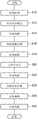
图1是第1实施方式所涉及的太阳能电池单元的制造方法的流程图。FIG. 1 is a flowchart of a method of manufacturing a solar cell according to the first embodiment.
图2(a)~图2(e)是第1实施方式所涉及的太阳能电池单元的制造方法的各工序中的半导体基板的概要剖视图。2( a ) to 2( e ) are schematic cross-sectional views of the semiconductor substrate in each step of the method of manufacturing the solar cell according to the first embodiment.
图3(a)~图3(d)是第1实施方式所涉及的太阳能电池单元的制造方法的各工序中的半导体基板的概要剖视图。3( a ) to 3( d ) are schematic cross-sectional views of the semiconductor substrate in each step of the method of manufacturing the solar cell according to the first embodiment.
图4是第2实施方式所涉及的太阳能电池单元的制造方法的流程图。4 is a flowchart of a method of manufacturing a solar battery cell according to the second embodiment.
图5(a)~图5(d)是第2实施方式所涉及的太阳能电池单元的制造方法的各工序中的半导体基板的概要剖视图。5( a ) to 5 ( d ) are schematic cross-sectional views of the semiconductor substrate in each step of the method of manufacturing a solar battery cell according to the second embodiment.
图6(a)~图6(c)是第2实施方式所涉及的太阳能电池单元的制造方法的各工序中的半导体基板的概要剖视图。6( a ) to 6( c ) are schematic cross-sectional views of the semiconductor substrate in each step of the method of manufacturing a solar battery cell according to the second embodiment.
图中:10-硅基板,12-发射极层,14-掩模,16-接触区域,18-掩模,20-防反射膜,20a-贯穿部,22-受光面电极,24-背面电极,100、200-太阳能电池。In the figure: 10-silicon substrate, 12-emitter layer, 14-mask, 16-contact area, 18-mask, 20-anti-reflection film, 20a-through part, 22-light-receiving surface electrode, 24-back electrode , 100, 200 - solar cells.
具体实施方式Detailed ways
以下,对本发明的具体实施方式进行详细说明。另外,以下叙述的结构为例示,并不限定本发明的范围。并且,附图说明中对相同的要件附加相同的符号,适当省略重复的说明。并且,在说明制造方法时示出的各剖视图中,半导体基板、其他层的厚度、大小均为方便说明的厚度、大小,并非表示实际的尺寸、比率。Hereinafter, specific embodiments of the present invention will be described in detail. In addition, the structure described below is an illustration and does not limit the scope of the present invention. In addition, in the description of the drawings, the same reference numerals are attached to the same elements, and overlapping descriptions are appropriately omitted. In addition, in each cross-sectional view shown in the description of the manufacturing method, the thickness and size of the semiconductor substrate and other layers are for convenience of description, and do not represent actual dimensions and ratios.
(第1实施方式)(first embodiment)
图1是第1实施方式所涉及的太阳能电池单元的制造方法的流程图。图2(a)~图2(e)是第1实施方式所涉及的太阳能电池单元的制造方法的各工序中的半导体基板的概要剖视图。图3(a)~图3(d)是第1实施方式所涉及的太阳能电池单元的制造方法的各工序中的半导体基板的概要剖视图。FIG. 1 is a flowchart of a method of manufacturing a solar cell according to the first embodiment. 2( a ) to 2( e ) are schematic cross-sectional views of the semiconductor substrate in each step of the method of manufacturing the solar cell according to the first embodiment. 3( a ) to 3( d ) are schematic cross-sectional views of the semiconductor substrate in each step of the method of manufacturing the solar cell according to the first embodiment.
在本实施方式中,对于将p型的单晶硅基板作为半导体基板来使用的情况进行说明,但也能够在使用n型的硅基板或多晶基板、其他p型或n型的化合物半导体基板的情况下适用本发明。以下,参照图1~图3对本实施方式所涉及的太阳能电池单元的制造方法进行说明。In this embodiment, the case where a p-type single crystal silicon substrate is used as a semiconductor substrate is described, but it is also possible to use an n-type silicon substrate or a polycrystalline substrate, or other p-type or n-type compound semiconductor substrates. The present invention is applicable under the circumstances. Hereinafter, a method for manufacturing a solar cell according to the present embodiment will be described with reference to FIGS. 1 to 3 .
首先,如图2(a)所示,通过以多线法对单晶硅锭进行切片来准备p型的硅基板10。接着,以碱溶液除去基板表面的由切片产生的损伤后,在受光面上形成最大高度为10μm左右的微细凹凸(纹理:图2(a)中不图示)(图1的S10)。通过基于这种凹凸结构的散射,能够得到光的禁闭效果,有助于转换效率的提高。First, as shown in FIG. 2( a ), a p-
接着,如图2(b)所示,在基板的受光面侧,通过离子注入将与基板相反导电型的n型掺杂剂注入整个面来形成n型的发射极层12(图1的S12)。Next, as shown in FIG. 2(b), on the light-receiving surface side of the substrate, an n-type dopant of the conductivity type opposite to that of the substrate is implanted into the entire surface by ion implantation to form an n-type emitter layer 12 (S12 in FIG. 1 ).
接着,如图2(c)所示,形成以发射极层12的预定区域露出的方式构图的掩模(图1的S14)。掩模能够使用通过光刻蚀法、印刷法来形成的掩模或硬掩模。Next, as shown in FIG. 2( c ), a mask patterned so as to expose a predetermined region of the
接着,如图2(d)所示,再次在基板的受光面侧,通过离子注入将与基板相反导电型的n型掺杂剂注入整个面。此时,在未被掩模包覆的、发射极层12的露出的预定区域12a(参照图2(c))选择性地注入离子。由此,在发射极层12的预定区域形成杂质浓度高于其他区域的接触区域16(图1的S16)。将如此在基板的一部分选择性地注入离子来形成杂质浓度较高的接触区域的方法叫作选择性发射极法。通过这些方法,将不需要离子注入的部位掩盖后进行离子注入,从而在基板的预定区域形成与未掩盖部分对应的选择性的离子注入图案。Next, as shown in FIG. 2( d ), again on the light-receiving surface side of the substrate, an n-type dopant having a conductivity type opposite to that of the substrate is implanted into the entire surface by ion implantation. At this time, ions are selectively implanted into the planned exposed
接着,如图2(e)所示,从硅基板10去除掩模14(图1的S18),对基板整体实施活性化退火处理(图1的S20)。Next, as shown in FIG. 2( e ), the
接着,如图3(a)所示,以掩盖接触区域16的方式形成掩模18(图1的S22)。而且,如图3(b)所示,在发射极层12的表面中被掩模18掩盖的区域以外的区域上,通过CVD法等形成SiN、TiO2等的防反射膜20(图1的S24)。防反射膜20的厚度例如为10~100nm左右。之后,如图3(c)所示,从硅基板10去除掩模18(图1的S26)。通过这些工序,能够在基板上形成以使接触区域16露出的方式构图的防反射膜20。Next, as shown in FIG. 3( a ), a
接着,如图3(d)所示,沿防反射膜20的图案,在接触区域16之上直接形成受光面电极22(图1的S30)。受光面电极22通过将以银(Ag)为主成分的受光面电极用浆料印刷为例如宽度50~100μm左右的梳状并烧成而形成。受光面电极22的高度为10~50μm左右。Next, as shown in FIG. 3( d ), the light-receiving
并且,在该阶段,背面电极24也通过使用以铝(Al)为主成分的背面电极用浆料进行印刷、烧成而形成。此时,浆料中所含的Al向硅基板10的内部扩散,在背面电极24附近形成p+层26。由此,能够得到BSF(Back SurfaceField:背表面场)效应。In addition, at this stage, the
另外,活性化退火处理也能够在进行离子注入后且图1的S18~S30之间适当地实施。并且,当在S12中的发射极层的形成、S16中的接触区域的形成中不利用离子注入法而是利用热扩散法等其他方法时,还能够省略活性化退火处理。In addition, the activation annealing treatment can also be appropriately performed after ion implantation and between S18 to S30 in FIG. 1 . In addition, when the formation of the emitter layer in S12 and the formation of the contact region in S16 do not use the ion implantation method but use other methods such as the thermal diffusion method, the activation annealing treatment can also be omitted.
通过以上工序制造出太阳能电池单元100。该太阳能电池单元100具备:硅基板10,其形成有发射极层12;防反射膜20,其覆盖发射极层12,并且以形成贯穿部20a的方式构图;及受光面电极22,其设置于以贯穿至硅基板10的发射极层12的方式形成于防反射膜20的贯穿部20a。贯穿部20a形成于发射极层12中杂质浓度高于其他区域的接触区域16的上方。The
由于在接触区域16之上不经过防反射膜20而直接形成有受光面电极22,因此构成受光面电极22的浆料材料的选定或浆料材料的烧成条件的选定及管理变得容易。其结果,可实现硅基板10与受光面电极22的低电阻导通。Since the light-receiving
并且,换言之,本实施方式所涉及的太阳能电池单元100的制造方法包括:防反射膜形成工序,在该工序中,在硅基板10上形成以使太阳能电池用硅基板10的受光面的一部分露出的方式构图的防反射膜20;及电极形成工序,在该工序中,将防反射膜20作为掩模,在硅基板10的露出的部分上形成受光面电极22。In addition, in other words, the method of manufacturing the
(第2实施方式)(Second embodiment)
图4是第2实施方式所涉及的太阳能电池单元的制造方法的流程图。图5(a)~图5(d)是第2实施方式所涉及的太阳能电池单元的制造方法的各工序中的半导体基板的概要剖视图。图6(a)~图6(c)是第2实施方式所涉及的太阳能电池单元的制造方法的各工序中的半导体基板的概要剖视图。4 is a flowchart of a method of manufacturing a solar battery cell according to the second embodiment. 5( a ) to 5 ( d ) are schematic cross-sectional views of the semiconductor substrate in each step of the method of manufacturing a solar battery cell according to the second embodiment. 6( a ) to 6( c ) are schematic cross-sectional views of the semiconductor substrate in each step of the method of manufacturing a solar battery cell according to the second embodiment.
以下,参考图4~图6对本实施方式所涉及的太阳能电池单元的制造方法进行说明。另外,对于与第1实施方式相同的结构或工序将说明适当省略。Hereinafter, a method for manufacturing the solar battery cell according to the present embodiment will be described with reference to FIGS. 4 to 6 . In addition, descriptions of the same configurations and steps as those of the first embodiment will be appropriately omitted.
首先,如图5(a)所示,通过以多线法对单晶硅锭进行切片来准备p型的硅基板10。接着,以碱溶液除去基板表面的由切片产生的损伤后,在受光面上形成最大高度为10μm左右的微细凹凸(纹理:图5(a)中不图示)(图4的S32)。First, as shown in FIG. 5( a ), a p-
接着,如图5(b)所示,在基板的受光面侧,通过离子注入将与基板相反导电型的n型掺杂剂注入整个面来形成n型的发射极层12(图4的S34)。Next, as shown in FIG. 5(b), on the light-receiving surface side of the substrate, an n-type dopant of the conductivity type opposite to that of the substrate is implanted into the entire surface by ion implantation to form an n-type emitter layer 12 (S34 in FIG. 4 ).
接着,如图5(c)所示,以将与通过后述的选择性发射极法形成的接触区域对应的预定部分掩盖的方式形成掩模18(图4的S36)。而且,如图5(d)所示,在发射极层12的表面中被掩模18掩盖的区域以外的区域上,通过CVD法等形成SiN、TiO2等防反射膜20(图4的S38)。之后,如图6(a)所示,从硅基板10去除掩模18(图4的S40)。通过这些工序,能够在硅基板10上形成以使硅基板10的受光面的一部分露出的方式构图的防反射膜20。Next, as shown in FIG. 5( c ), a
接着,如图6(b)所示,再次在硅基板10的受光面侧,通过离子注入将与硅基板10相反导电型的n型掺杂剂注入整个面。此时,将防反射膜20作为掩模,在露出的部分注入杂质来形成接触区域16。即,在未被防反射膜20包覆的、发射极层12的露出的预定区域12a(参照图6(a))选择性地注入离子。由此,在发射极层12的预定区域形成杂质浓度高于其他区域的接触区域16(图4的S42)。之后,对基板整体实施活性化退火处理(图4的S44)。Next, as shown in FIG. 6( b ), again on the light-receiving surface side of the
在此,通过离子注入中的n型掺杂剂的能量,有时n型掺杂剂会穿透防反射膜20而到达发射极层,有可能使发射极层的性能降低。因此,优选适当选择防反射膜20的膜厚、离子注入的能量,以使注入于防反射膜20的n型掺杂剂的大部分不会到达发射极层。Here, depending on the energy of the n-type dopant during ion implantation, the n-type dopant may penetrate the
接着,如图6(c)所示,沿防反射膜20的图案,在接触区域16之上直接形成受光面电极22(图4的S46)。受光面电极22的形成方法与第1实施方式相同。并且,在该阶段,还形成背面电极24。背面电极24的形成方法与第1实施方式相同。此时,背面电极用浆料中所含的Al向硅基板10的内部扩散,在背面电极24附近形成p+层26。由此,能够得到BSF(Back SurfaceField)效应。Next, as shown in FIG. 6( c ), the light-receiving
通过以上工序,制造出与第1实施方式所涉及的太阳能电池单元100相同结构的太阳能电池单元200。由于在接触区域16之上不经过防反射膜20而直接形成有受光面电极22,因此构成受光面电极22的浆料材料的选定、浆料材料的烧成条件的选定及管理变得容易。并且,与第1实施方式所涉及的制造方法相比较,第2实施方式所涉及的制造方法无需利用2种不同的掩模,而是将防反射膜20作为掩模之一来进行利用,从而能够降低专用掩模的数量。而且,通过使用了防反射膜20的图案的自对准,沿发射极层12的露出的部分形成接触区域16。其结果,对位精确度提高,并且实现了硅基板10与受光面电极22的低电阻导通。Through the above steps, the
并且,换言之,本实施方式所涉及的太阳能电池单元200的制造方法也包括:防反射膜形成工序,在该工序中,在硅基板10上形成以使太阳能电池用硅基板10的受光面的一部分露出的方式构图的防反射膜20;及电极形成工序,在该工序中,将防反射膜20作为掩模,在硅基板10的露出的接触区域16之上形成受光面电极22。In addition, in other words, the method of manufacturing the
根据该方法,由于能够将防反射膜20作为掩模而沿发射极层12的露出的部分形成接触区域16,因此能够容易地提高受光面电极22与基板的接触区域16的对位精确度。并且,由于在接触区域16之上不经过防反射膜20而直接形成有受光面电极22,因此构成受光面电极22的浆料材料的选定、浆料材料的烧成条件的选定及管理变得容易。其结果,对位精确度提高,并且实现了硅基板10与受光面电极22的低电阻导通。According to this method, since the
并且,在发射极层12上以离子注入来形成接触区域16时的掺杂离子的注入射程选择为防反射膜20的膜厚以下。因此,注入于防反射膜20的离子不会透过防反射膜20而到达至发射极层12,其大部分会停留在防反射膜20中。其结果,不会对发射极层12的剂量带来太大的影响。In addition, when the
并且,作为图4的工序S36(对应于图5(c))中的掩模,优选使用能够在真空装置内相对于基板表面接触分离的硬掩模、模板掩模等。由此,可暂且不回到大气中,而在连续的真空环境下进行图4所示的工序S34至工序S42的处理,装置的直线排列变得容易。另外,掩模根据其形状与掩模部的尺寸也可以使用钢丝等。进而,若在图4的工序S44中采用闪光灯退火等能够在真空层内进行处理的退火方法,则可暂且不回到大气中,而在连续的真空环境下进行图4所示的工序S34至工序S44的处理。In addition, as the mask in step S36 of FIG. 4 (corresponding to FIG. 5( c )), it is preferable to use a hard mask, a stencil mask, or the like that can be contacted and separated from the substrate surface in a vacuum apparatus. Thereby, the processing from step S34 to step S42 shown in FIG. 4 can be performed in a continuous vacuum environment without returning to the atmosphere temporarily, and the linear arrangement of the apparatus becomes easy. In addition, steel wire etc. can also be used for a mask according to the shape and the size of a mask part. Furthermore, if an annealing method that can be processed in a vacuum layer such as flash lamp annealing is used in the step S44 of FIG. 4, the steps S34 to S34 shown in FIG. Processing of step S44.
如上述,根据各实施方式所涉及的太阳能电池单元的制造方法,在受光面电极22的烧成时,无需浸透于防反射膜20的内部来与硅基板10导通,因此能够放宽烧成条件的范围,实现控制的容易化、太阳能电池单元的质量的稳定化。As described above, according to the method of manufacturing a solar battery cell according to each embodiment, when the light-receiving
以上,参照上述各实施方式对本发明进行了说明,但本发明不限定于上述实施方式,对各实施方式的结构进行适当地组合或转换的方式也包含于本发明中。并且,也能够基于本领域技术人员的知识而在各实施方式中的离子注入装置、运输容器等中对实施方式加以各种设计变更等变形,被加以这种变形的实施方式也包含于本发明的范围内。As mentioned above, although this invention was demonstrated with reference to each said embodiment, this invention is not limited to said embodiment, The form which suitably combines or converts the structure of each embodiment is also included in this invention. Furthermore, various modifications such as design changes can be added to the ion implantation apparatus, the transport container, etc. in each embodiment based on the knowledge of those skilled in the art, and the embodiments to which such modifications are added are also included in the present invention. In the range.
本申请主张基于2012年2月20日申请的日本专利申请第2012-034286号的优先权。该申请的全部内容通过参考援用于本说明书中。This application claims priority based on Japanese Patent Application No. 2012-034286 filed on February 20, 2012. The entire content of this application is incorporated in this specification by reference.
Claims (4)
Applications Claiming Priority (2)
| Application Number | Priority Date | Filing Date | Title |
|---|---|---|---|
| JP2012-034286 | 2012-02-20 | ||
| JP2012034286AJP2013171943A (en) | 2012-02-20 | 2012-02-20 | Method for manufacturing solar cell and solar cell |
Publications (1)
| Publication Number | Publication Date |
|---|---|
| CN103258904Atrue CN103258904A (en) | 2013-08-21 |
Family
ID=48962716
Family Applications (1)
| Application Number | Title | Priority Date | Filing Date |
|---|---|---|---|
| CN2013100550952APendingCN103258904A (en) | 2012-02-20 | 2013-02-20 | Method of manufacturing solar cell, and solar cell |
Country Status (5)
| Country | Link |
|---|---|
| US (1) | US20130213466A1 (en) |
| JP (1) | JP2013171943A (en) |
| KR (1) | KR20130095673A (en) |
| CN (1) | CN103258904A (en) |
| TW (1) | TW201347209A (en) |
Families Citing this family (3)
| Publication number | Priority date | Publication date | Assignee | Title |
|---|---|---|---|---|
| US9680045B2 (en) | 2015-06-25 | 2017-06-13 | International Business Machines Corporation | III-V solar cell structure with multi-layer back surface field |
| KR20170019597A (en)* | 2015-08-12 | 2017-02-22 | 엘지전자 주식회사 | Solar cell and manufacturing method thereof |
| EP3818570A4 (en)* | 2018-07-05 | 2022-04-20 | UNM Rainforest Innovations | COST-EFFECTIVE CRACK-RESISTANT SCREEN-PRINTABLE METALLIZATION FOR INCREASED MODULE RELIABILITY |
Citations (3)
| Publication number | Priority date | Publication date | Assignee | Title |
|---|---|---|---|---|
| US4070689A (en)* | 1975-12-31 | 1978-01-24 | Motorola Inc. | Semiconductor solar energy device |
| US4131488A (en)* | 1975-12-31 | 1978-12-26 | Motorola, Inc. | Method of semiconductor solar energy device fabrication |
| US5011565A (en)* | 1989-12-06 | 1991-04-30 | Mobil Solar Energy Corporation | Dotted contact solar cell and method of making same |
Family Cites Families (1)
| Publication number | Priority date | Publication date | Assignee | Title |
|---|---|---|---|---|
| JPS6215864A (en)* | 1985-07-15 | 1987-01-24 | Hitachi Ltd | How to manufacture solar cells |
- 2012
- 2012-02-20JPJP2012034286Apatent/JP2013171943A/enactivePending
- 2013
- 2013-01-25TWTW102102922Apatent/TW201347209A/enunknown
- 2013-02-07KRKR1020130013995Apatent/KR20130095673A/ennot_activeCeased
- 2013-02-20USUS13/771,880patent/US20130213466A1/ennot_activeAbandoned
- 2013-02-20CNCN2013100550952Apatent/CN103258904A/enactivePending
Patent Citations (3)
| Publication number | Priority date | Publication date | Assignee | Title |
|---|---|---|---|---|
| US4070689A (en)* | 1975-12-31 | 1978-01-24 | Motorola Inc. | Semiconductor solar energy device |
| US4131488A (en)* | 1975-12-31 | 1978-12-26 | Motorola, Inc. | Method of semiconductor solar energy device fabrication |
| US5011565A (en)* | 1989-12-06 | 1991-04-30 | Mobil Solar Energy Corporation | Dotted contact solar cell and method of making same |
Also Published As
| Publication number | Publication date |
|---|---|
| KR20130095673A (en) | 2013-08-28 |
| US20130213466A1 (en) | 2013-08-22 |
| JP2013171943A (en) | 2013-09-02 |
| TW201347209A (en) | 2013-11-16 |
Similar Documents
| Publication | Publication Date | Title |
|---|---|---|
| US9082908B2 (en) | Solar cell | |
| US9209332B2 (en) | Solar cell element and solar cell module | |
| JP2005310830A (en) | Solar cell and method for manufacturing solar cell | |
| JP2011507246A (en) | Back electrode type solar cell having wide backside emitter region and method for manufacturing the same | |
| US9893229B2 (en) | Method for manufacturing a photovoltaic cell with selective doping | |
| JP5734447B2 (en) | Photovoltaic device manufacturing method and photovoltaic device | |
| US20120264253A1 (en) | Method of fabricating solar cell | |
| JP6363335B2 (en) | Photoelectric device and method for manufacturing photoelectric device | |
| WO2010001473A1 (en) | Photovoltaic system and manufacturing method thereof | |
| CN103928567B (en) | Solar cell and method for manufacturing the same | |
| US20110186118A1 (en) | Method of doping impurities, method of manufacturing a solar cell using the method and solar cell manufactured by using the method | |
| CN103258904A (en) | Method of manufacturing solar cell, and solar cell | |
| JP4325912B2 (en) | Solar cell element and manufacturing method thereof | |
| KR20120009682A (en) | Solar cell manufacturing method | |
| KR101823597B1 (en) | Solar cell and manufacturing method thereof | |
| JP6238884B2 (en) | Photovoltaic element and manufacturing method thereof | |
| KR20120004174A (en) | Back electrode solar cell and manufacturing method thereof | |
| TW201431108A (en) | A process of manufacturing an interdigitated back-contact solar cell | |
| CN104183668A (en) | Manufacturing method of solar cell unit | |
| KR101798967B1 (en) | Method for manufacturing solar cell | |
| KR101929444B1 (en) | Solar cell and method for manufacturing the same | |
| JP6422455B2 (en) | Photoelectric conversion device and method for manufacturing photoelectric conversion device | |
| KR20170119028A (en) | Method for back contact silicon solar cell | |
| JP2012186402A (en) | Manufacturing method of solar cell |
Legal Events
| Date | Code | Title | Description |
|---|---|---|---|
| C06 | Publication | ||
| PB01 | Publication | ||
| C10 | Entry into substantive examination | ||
| SE01 | Entry into force of request for substantive examination | ||
| C02 | Deemed withdrawal of patent application after publication (patent law 2001) | ||
| WD01 | Invention patent application deemed withdrawn after publication | Application publication date:20130821 |