CN103257076A - Artificial hip joint dynamic fatigue wear sample clamp and tester - Google Patents
Artificial hip joint dynamic fatigue wear sample clamp and testerDownload PDFInfo
- Publication number
- CN103257076A CN103257076ACN2013102022570ACN201310202257ACN103257076ACN 103257076 ACN103257076 ACN 103257076ACN 2013102022570 ACN2013102022570 ACN 2013102022570ACN 201310202257 ACN201310202257 ACN 201310202257ACN 103257076 ACN103257076 ACN 103257076A
- Authority
- CN
- China
- Prior art keywords
- sample
- hip joint
- artificial hip
- femoral head
- testing machine
- Prior art date
- Legal status (The legal status is an assumption and is not a legal conclusion. Google has not performed a legal analysis and makes no representation as to the accuracy of the status listed.)
- Pending
Links
- 210000004394hip jointAnatomy0.000titleclaimsabstractdescription33
- 238000012360testing methodMethods0.000claimsabstractdescription37
- 230000005540biological transmissionEffects0.000claimsdescription34
- 230000001050lubricating effectEffects0.000claimsdescription9
- 230000003014reinforcing effectEffects0.000claimsdescription8
- 239000012530fluidSubstances0.000claimsdescription6
- NJPPVKZQTLUDBO-UHFFFAOYSA-NnovaluronChemical compoundC1=C(Cl)C(OC(F)(F)C(OC(F)(F)F)F)=CC=C1NC(=O)NC(=O)C1=C(F)C=CC=C1FNJPPVKZQTLUDBO-UHFFFAOYSA-N0.000claims1
- 210000000588acetabulumAnatomy0.000abstractdescription5
- 239000003638chemical reducing agentSubstances0.000abstractdescription4
- 230000008901benefitEffects0.000abstractdescription3
- 230000033001locomotionEffects0.000description6
- 238000002054transplantationMethods0.000description6
- 238000011160researchMethods0.000description4
- 210000000689upper legAnatomy0.000description4
- 238000010586diagramMethods0.000description3
- 239000007788liquidSubstances0.000description3
- 238000000034methodMethods0.000description3
- 230000001360synchronised effectEffects0.000description3
- 201000010099diseaseDiseases0.000description2
- 208000037265diseases, disorders, signs and symptomsDiseases0.000description2
- 238000011835investigationMethods0.000description2
- 239000000463materialSubstances0.000description2
- 241000309551Arthraxon hispidusSpecies0.000description1
- 208000020084Bone diseaseDiseases0.000description1
- 208000012661DyskinesiaDiseases0.000description1
- 208000012659Joint diseaseDiseases0.000description1
- 239000004698PolyethyleneSubstances0.000description1
- 230000001133accelerationEffects0.000description1
- 230000009471actionEffects0.000description1
- 238000007792additionMethods0.000description1
- 230000009286beneficial effectEffects0.000description1
- 239000000919ceramicSubstances0.000description1
- 238000006243chemical reactionMethods0.000description1
- 230000006835compressionEffects0.000description1
- 238000007906compressionMethods0.000description1
- 238000013480data collectionMethods0.000description1
- 238000013461designMethods0.000description1
- 230000000694effectsEffects0.000description1
- 238000005516engineering processMethods0.000description1
- 230000007613environmental effectEffects0.000description1
- 210000001624hipAnatomy0.000description1
- 238000002513implantationMethods0.000description1
- 230000006872improvementEffects0.000description1
- 238000007689inspectionMethods0.000description1
- 238000009434installationMethods0.000description1
- 238000005461lubricationMethods0.000description1
- 230000007246mechanismEffects0.000description1
- 239000002184metalSubstances0.000description1
- 238000012986modificationMethods0.000description1
- 230000004048modificationEffects0.000description1
- 230000000399orthopedic effectEffects0.000description1
- -1polyethylenePolymers0.000description1
- 229920000573polyethylenePolymers0.000description1
- 230000008569processEffects0.000description1
- 238000012545processingMethods0.000description1
- 230000009467reductionEffects0.000description1
- 238000005070samplingMethods0.000description1
- 238000004088simulationMethods0.000description1
Images

Landscapes
- Prostheses (AREA)
Abstract
Description
Translated fromChinese技术领域technical field
本发明涉及医疗器械技术领域,具体是涉及一种人工髋关节动态疲劳磨损试验夹具及试验机。The invention relates to the technical field of medical devices, in particular to a jig and a testing machine for dynamic fatigue wear testing of artificial hip joints.
背景技术Background technique
随着生活节奏的不断加快,面对日趋增长的生活压力,患骨科疾病类人数呈逐年上升的趋势。在众多的骨类疾病中,髋关节疾病以涉及人员年龄范围呈扩大趋势受到广泛关注。目前该类疾病最为有效地治疗途径是进行人工髋关节移植手术。植入人体的人工髋关节在人体内部病患处起到原关节的作用,但是因人体内部的生理环境复杂,加之人工髋关节选材从金属、陶瓷到高分子聚乙烯等各不相同,随着移植时间的不断增长,人工髋关节开始出现疲劳失效现象。目前的研究分析与临床实践证明,人工髋关节的关节头(俗称人工股骨头)与人工髋臼在频繁改变的载荷的作用下,伴随着滑动产生的摩擦磨损是造成人工髋关节在移植之后失效的主要原因。为此,预测人工髋关节在移植后出现失效的时期、明确产生的磨损失效的主要因素和作用的机理,已备进一步改进人工髋关节的设计,成为延长髋关节移植手术效果的目标之一。目前,用于研究的人工髋关节的疲劳摩擦磨损的手段集中于采用人工髋关节摩擦磨损试验机和临床移植后期的病例调查研究两种方式。人工髋关节摩擦磨损试验机是目前研究中采用的最为理想的手段,可较为理想的模拟人工髋关节在植入后的运动和受力情况,在一定程度上满足了现实的需求;临床移植后期的病例调查因其取样不便且代价高,只适用于最终的结果的对比和性能改进参照。现阶段国内应用于模拟人工髋关节疲劳磨损的试验机多局限于仿制或改进国外原有的产品,且数量不多,技术不够成熟。With the continuous acceleration of the pace of life and the increasing pressure of life, the number of people suffering from orthopedic diseases is on the rise year by year. Among the numerous bone diseases, hip joint diseases have attracted widespread attention due to the fact that the age range of the involved persons is expanding. At present, the most effective treatment for this type of disease is artificial hip transplantation. The artificial hip joint implanted in the human body plays the role of the original joint in the diseased part of the human body. However, due to the complex physiological environment inside the human body, and the selection of materials for artificial hip joints varies from metal, ceramics to high molecular polyethylene, etc., with the As the transplantation time continued to increase, artificial hip joints began to experience fatigue failure. The current research analysis and clinical practice have proved that the joint head of the artificial hip joint (commonly known as the artificial femoral head) and the artificial acetabulum are under the action of frequently changing loads, and the friction and wear accompanied by sliding are the main reasons for the failure of the artificial hip joint after transplantation. the main reason. For this reason, predicting the failure period of artificial hip joints after transplantation, clarifying the main factors and mechanism of wear and tear failure, and further improving the design of artificial hip joints has become one of the goals of prolonging the effect of hip joint transplantation. At present, the means of artificial hip joint fatigue friction and wear research are concentrated in two ways: artificial hip joint friction and wear testing machine and clinical case investigation and research in the later stage of clinical transplantation. The artificial hip joint friction and wear testing machine is the most ideal method used in the current research, which can ideally simulate the movement and stress of the artificial hip joint after implantation, and meets the actual needs to a certain extent; Due to the inconvenience and high cost of sampling, the case investigation is only suitable for the comparison of the final results and the performance improvement reference. At present, domestic testing machines used to simulate fatigue and wear of artificial hip joints are mostly limited to imitating or improving foreign original products, and the number is not large, and the technology is not mature enough.
申请号是200520078197.7、申请名称是“往复式股骨摩擦磨损试验机”的实用新型专利中公开了一种试验机,该机由工作台、设在工作台上的下试样夹具小车、骑在下试样夹具小车上方的上试样夹具、V型导轨以及变频调速器和数据采集系统构成,上试样夹具设在固定于底座两侧的V型导轨内,工作台上还设有动力传动装置,其下方设有控制台的往复运动换向装置,下试样夹具小车与固定在工作台上的传感器刚性连接。试验时,将股骨试样安装在上、下夹具中,通过砝码以及滑块和夹具的自重对摩擦副加载,在加载状态下,上、下试样垂直接触相交。当开启电机后,电机的运动通过电机带轮、传动带、丝杠带轮传动丝杠,在左右两个行程开关的控制下,使工作台产生水平方向上的往复运动,实现试样往复摩擦磨损。本实用新型的优点在于使用了可沿着V形导轨上下浮动的上试样夹具以模拟股骨实际工作状态,以拉压传感器测量运动时摩擦力,从而提高了试验精度,但是放置在该试样夹具中的股骨与人体中的股骨之间具有较大的环境差异,砝码与拉压传感器的结合无法提供一种动态的连续受力。The application number is 200520078197.7, and the application name is "reciprocating femoral friction and wear testing machine". A testing machine is disclosed in the utility model patent. The upper sample fixture above the sample fixture trolley, V-shaped guide rail, frequency conversion speed regulator and data acquisition system are composed. The upper sample fixture is set in the V-shaped guide rail fixed on both sides of the base, and a power transmission device is also installed on the workbench. , the reciprocating motion reversing device of the console is arranged below it, and the lower sample fixture trolley is rigidly connected with the sensor fixed on the workbench. During the test, the femur sample was installed in the upper and lower fixtures, and the friction pair was loaded by the weight and the self-weight of the slider and the fixture. In the loaded state, the upper and lower samples were in vertical contact and intersected. When the motor is turned on, the movement of the motor passes through the motor pulley, the transmission belt, and the screw pulley to drive the lead screw. Under the control of the left and right travel switches, the worktable generates reciprocating motion in the horizontal direction to realize the reciprocating friction and wear of the sample. . The utility model has the advantage of using the upper sample fixture that can float up and down along the V-shaped guide rail to simulate the actual working state of the femur, and measuring the friction force during movement with a tension and pressure sensor, thereby improving the test accuracy. There is a large environmental difference between the femur in the fixture and the femur in the human body, and the combination of weights and tension and compression sensors cannot provide a dynamic continuous force.
发明内容Contents of the invention
本发明的目的在于提供一种能够实现模拟人工髋关节植入人体后的运动、受力和润滑状态,测试不同材料髋关节假体在一定条件下的动态疲劳磨损状况的试验机,为临床应用提供较为准确可靠地实验数据,并弥补国内在人工髋关节动态疲劳磨损模拟试验机方面的不足。采用的技术方案是:一种人工髋关节动态疲劳磨损试样夹具,包括带动股骨头试样转动的股骨头试样固定部件和髋臼试样固定部件,其特征在于:所述髋臼试样固定部件包括底座和斜托盘,髋臼试样安装在所述底座上;所述底座置于斜托盘中。The purpose of the present invention is to provide a testing machine capable of simulating the movement, stress and lubrication state of artificial hip joints implanted in the human body, and testing the dynamic fatigue and wear conditions of hip joint prostheses made of different materials under certain conditions. Provide more accurate and reliable experimental data, and make up for the shortcomings of domestic artificial hip joint dynamic fatigue wear simulation testing machines. The technical solution adopted is: a fixture for dynamic fatigue wear of an artificial hip joint, including a femoral head sample fixing part and an acetabular sample fixing part that drives the femoral head sample to rotate, and is characterized in that: the acetabular sample The fixing part includes a base and an inclined tray, on which the acetabular sample is installed; and the base is placed in the inclined tray.
本发明的技术特征还有:所述试样夹具还包括盛放润滑液的套杯,所述套杯设有润滑液排出口。The technical feature of the present invention is that the sample holder also includes a cup for containing lubricating fluid, and the cup is provided with a lubricating fluid outlet.
本发明的技术方案还有:一种人工髋关节疲劳磨损试验机,该机包括位于试验机上部的股骨头试样转动部分、权利要求1所述试样夹具和试样加载部分,其特征在于:所述股骨头试样转动部分包括转动电机及在该电机带动下转动的上主轴,所述上主轴的下端部开有用于安装股骨头试样的尾部锥孔;所述试样加载部分包括加载电机、减速装置和对髋臼试样施加载荷的加载传动部件。The technical solution of the present invention also includes: an artificial hip joint fatigue wear testing machine, which includes a rotating part of the femoral head sample located on the upper part of the testing machine, a sample clamp and a sample loading part according to claim 1, characterized in that : the rotating part of the femoral head sample includes a rotating motor and an upper spindle driven by the motor, the lower end of the upper spindle is provided with a tail taper hole for installing the femoral head sample; the sample loading part includes Loading motor, reduction gear and loading transmission components for applying load to acetabular specimen.
本发明的技术特征还有:所述加载传动部件包括在所述加载电机带动下转动的传动丝杠、与传动丝杠配合的传动螺母、柔性加力部件和传感部件。The technical features of the present invention also include: the loading transmission part includes a transmission screw driven by the loading motor, a transmission nut matched with the transmission screw, a flexible force component and a sensing component.
本发明的技术特征还有:所述柔性加力部件包括套装在所述传动螺母上的加力弹簧,所述加力弹簧的另一端装在传力螺母的凹槽内,传力螺母的内孔中装有传动螺杆且该传动螺杆装在组合支撑架的孔中,所述组合支撑架的上部还装有导向下主轴,所述斜托盘的下端面上开有与所述导向下主轴配合的凹槽。The technical features of the present invention also include: the flexible reinforcing part includes a reinforcing spring set on the driving nut, the other end of the reinforcing spring is installed in the groove of the driving nut, and the inner part of the driving nut A drive screw is installed in the hole and the drive screw is installed in the hole of the combined support frame. The upper part of the combined support frame is also equipped with a guide lower spindle. groove.
本发明的技术特征还有:所述传感部件包括轴向力传感器,所述轴向力传感器装在所述传动螺杆的上端。The technical feature of the present invention is that the sensing part includes an axial force sensor, and the axial force sensor is installed on the upper end of the driving screw.
本发明的技术特征还有:所述传感部件还包括拉压力传感器,所述拉压力传感器的安装在所述组合支撑架的侧壁上。The technical feature of the present invention is that the sensing part further includes a tension and pressure sensor, and the tension and pressure sensor is installed on the side wall of the combined support frame.
本发明的技术特征还有:在所述上主轴尾部锥孔的上方还开有一个垂直于尾部锥孔的横向通孔。 The technical feature of the present invention is that a transverse through hole perpendicular to the tail taper hole is opened above the tail taper hole of the upper main shaft. the
本发明的有益效果在于:1)本试样夹具结构简单、安装便利,股骨头试样通过锥孔直接卡装入位,股骨头与髋关节试样之间具有23??夹角;同时可根据试验要求分别进行有介质试验和干摩擦试验,从而完全模仿了人体的实际结构,为准确试验数据的提供打下了基础;The beneficial effects of the present invention are as follows: 1) The sample fixture has simple structure and convenient installation, the femoral head sample is directly snapped into place through the taper hole, and there is an included angle of 23?? between the femoral head and the hip joint sample; According to the test requirements, the medium test and the dry friction test are respectively carried out, thus completely imitating the actual structure of the human body and laying the foundation for the provision of accurate test data;
2)本试验机为立式结构,试样夹具及装在该夹具中的试样位于本机中间位置,试样受力方向与人体结构一致;在计算机程序控制下,柔性加力部件和传感部件配合使用实现了载荷的精确施加,为试验提供了准确数据;2) The testing machine has a vertical structure, the sample fixture and the sample installed in the fixture are located in the middle of the machine, and the force direction of the sample is consistent with the human body structure; The use of sensing parts together realizes the precise application of the load and provides accurate data for the test;
3)本试验机具有结构先进、控制精确、试验数据可靠性高的优点。3) This testing machine has the advantages of advanced structure, precise control and high reliability of test data.
附图说明Description of drawings
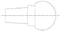
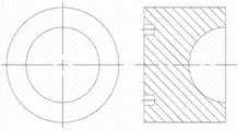
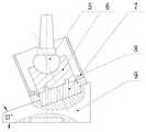
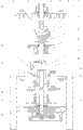
附图1是股骨头试样结构示意图,附图2是髋臼试样结构示意图,附图3是夹具结构原理示意图,附图4是本试验机主视图,附图5是附图4的左视图,其中1是转动电机,2是同步带轮,3是同步带,4是上主轴,5是股骨头试样,6是髋臼试样,7是底座,8是套杯,9是斜托盘,10是导向下主轴,11是轴向力传感器,12是拉压力传感器,13是传动螺杆,14是传力螺母,15是加力弹簧,16是传动螺母,17是传动丝杠,18是下吊杆,19是涡轮蜗杆,20是加载电机,21是基座,22是支撑杆,23是上层板,24是下层板,25是组合支撑架。Accompanying drawing 1 is a schematic diagram of the structure of the femoral head sample, accompanying drawing 2 is a schematic diagram of the structure of the acetabular sample, accompanying drawing 3 is a schematic diagram of the principle of the fixture structure, accompanying drawing 4 is the front view of the testing machine, and accompanying
具体实施方式Detailed ways
下面结合附图,对本发明的具体实施方式进行说明。一种人工髋关节动态疲劳磨损试样夹具,包括带动股骨头转动的股骨头试样固定部件和髋臼试样固定部件,其中髋臼试样固定部件包括底座7和斜托盘9,髋臼试样6直接放置在底座7中,底座7置于斜托盘9中, 且斜托盘9 与水平方向之间具有一个夹角,该夹角依据人体实际结构制定,一般是23?? 。使用时,将股骨头试样5快速装在股骨头试样固定部件中,将髋臼试样6通过髋臼试样6底部的圆形凹槽置于底座7中,再将底座7置于斜托盘9中。若是需要有润滑介质参与试验,则加装套杯8,并向套杯8中加入润滑液,润滑液的加入量以人工关节接触处有液体存在为宜。在套杯8的底部设有润滑液排出口,以使使用后的润滑液顺利排出。The specific implementation manners of the present invention will be described below in conjunction with the accompanying drawings. An artificial hip joint dynamic fatigue wear sample fixture, including a femoral head sample fixing part and an acetabular sample fixing part that drives the femoral head to rotate, wherein the acetabular sample fixing part includes a
本发明还公开了一种人工髋关节疲劳磨损试验机,该机包括位于试验机上部的股骨头试样转动部分、夹持待试验试样的试样夹具和试样加载部分。股骨头试样转动部分包括转动电机1及在该电机带动下转动的上主轴4,上主轴4的下端部开有用于安装股骨头试样5的尾部锥孔,在上主轴4的尾部锥孔的上方还开有一个垂直于尾部锥孔的横向通孔。将股骨头试样5安装在上主轴4的尾部锥孔中,且检查后保证没有异动产生即可,横向通孔用于股骨头试样5的拆卸。转动电机1通过同步带传动后带动上主轴4转动,进而带动股骨头试样5转动。The invention also discloses an artificial hip joint fatigue wear testing machine, which includes a rotating part of a femoral head sample located on the upper part of the testing machine, a sample clamp for clamping a sample to be tested, and a sample loading part. The rotating part of the femoral head sample includes a rotating motor 1 and an upper spindle 4 that rotates under the drive of the motor. The lower end of the upper spindle 4 is provided with a tail taper hole for installing the
试样加载部分包括加载电机20、与加载电机20 连接的涡轮蜗杆减速器19和对髋臼试样6施加载荷的加载传动部件。加载传动部件包括在加载电机20、涡轮蜗杆减速器19带动下转动的传动丝杠17、与传动丝杠17配合的传动螺母16、给髋臼试样6柔性加力的柔性加力部件和反馈加力大小的传感部件。其中柔性加力部件包括套装在传动螺母16上的加力弹簧15,该加力弹簧15的另一端装在传力螺母14的凹槽内,在传力螺母14的内孔中通过螺纹装有传动螺杆13且该传动螺杆13装在组合支撑架25上的孔中,组合支撑架25的上部还装有导向下主轴10,斜托盘9的下端面上开有与导向下主轴10配合的凹槽。当加载电机20转动时,经过涡轮蜗杆减速器19减速,传动丝杠17转动,在传动丝杠17带动下,传动螺母16可上移,从而压缩加力弹簧15,加力弹簧15受压后,向上伸展推动传力螺母14和与之装配在一起的传动螺杆13向上运动,带动安装在传动螺杆13上端的轴向力传感器11与其随之运动,当轴向力传感器11上端与导向下主轴10接触后, 从而由导向下主轴10给斜托盘9施加作用力,达到加力的目的。复位过程在此不再叙述。The sample loading part includes a loading motor 20, a worm gear reducer 19 connected with the loading motor 20 and a loading transmission part that applies a load to the
传感部件包括轴向力传感器11和拉压力传感器12,轴向力传感器11装在传动螺杆13的上端,当传动螺杆13上移后,轴向力传感器11测出轴向力大小并通过计算机控制程序进行相关控制。拉压力传感器12安装在轴向力传感器11的组合支撑架25内壁上,当轴向力传感器11运动到和导向下主轴10接触时,拉压力传感器12同导向下主轴10连接的部分开始运动,拉压力传感器12测出此时的拉力或压力力矩,输入到计算机,进行数据的采集处理。The sensing components include an axial force sensor 11 and a tension and pressure sensor 12. The axial force sensor 11 is installed on the upper end of the
当然,上述说明并非对本发明的限制,本发明也不仅限于上述举例,本技术领域的普通技术人员在本发明的实质范围内所做出的变化、改型、添加或替换,也属于本发明的保护范围。Of course, the above description is not a limitation of the present invention, and the present invention is not limited to the above examples. Changes, modifications, additions or replacements made by those skilled in the art within the scope of the present invention also belong to the scope of the present invention. protected range.
Claims (8)
Translated fromChinesePriority Applications (1)
| Application Number | Priority Date | Filing Date | Title |
|---|---|---|---|
| CN2013102022570ACN103257076A (en) | 2013-05-27 | 2013-05-27 | Artificial hip joint dynamic fatigue wear sample clamp and tester |
Applications Claiming Priority (1)
| Application Number | Priority Date | Filing Date | Title |
|---|---|---|---|
| CN2013102022570ACN103257076A (en) | 2013-05-27 | 2013-05-27 | Artificial hip joint dynamic fatigue wear sample clamp and tester |
Publications (1)
| Publication Number | Publication Date |
|---|---|
| CN103257076Atrue CN103257076A (en) | 2013-08-21 |
Family
ID=48961126
Family Applications (1)
| Application Number | Title | Priority Date | Filing Date |
|---|---|---|---|
| CN2013102022570APendingCN103257076A (en) | 2013-05-27 | 2013-05-27 | Artificial hip joint dynamic fatigue wear sample clamp and tester |
Country Status (1)
| Country | Link |
|---|---|
| CN (1) | CN103257076A (en) |
Cited By (15)
| Publication number | Priority date | Publication date | Assignee | Title |
|---|---|---|---|---|
| CN104297091A (en)* | 2014-10-23 | 2015-01-21 | 桂林电子科技大学 | Novel artificial hip joint friction testing machine |
| CN104359780A (en)* | 2014-11-28 | 2015-02-18 | 济南大学 | Femoral head handle bulb frictional wear testing device |
| CN104990790A (en)* | 2015-07-07 | 2015-10-21 | 苏州热工研究院有限公司 | Clamp for sliding abrasion test |
| CN105223010A (en)* | 2015-10-12 | 2016-01-06 | 中国矿业大学 | A Parallel Bionic Knee-Hip Joint Testing Machine |
| CN105276354A (en)* | 2015-10-19 | 2016-01-27 | 中国矿业大学 | Self-lubricating structure of hip joint testing machine and working method thereof |
| CN105891036A (en)* | 2016-05-23 | 2016-08-24 | 西南交通大学 | Impacting-sliding composite frictional wear testing device and method thereof |
| CN107505192A (en)* | 2017-06-23 | 2017-12-22 | 天津市天津医院 | Acetabular bone simulation fixture and preparation method thereof |
| CN107727523A (en)* | 2017-10-18 | 2018-02-23 | 浙江工业大学 | A kind of multifunction manual hip joint abrasion tester |
| CN108007684A (en)* | 2017-12-28 | 2018-05-08 | 天津市医疗器械质量监督检验中心 | Femoral hip stem fatigue test loading device |
| CN108387508A (en)* | 2018-01-25 | 2018-08-10 | 西北有色金属研究院 | A kind of experimental rig with metal fatigue and frictional behaviour detection function |
| CN108593475A (en)* | 2018-06-04 | 2018-09-28 | 辽宁工程技术大学 | Artificial knee joint meniscus erosive wear experimental bench |
| CN110024752A (en)* | 2019-05-22 | 2019-07-19 | 吉林大学 | A kind of fixture for insect leg joint friction test |
| CN110595892A (en)* | 2019-10-18 | 2019-12-20 | 影为医疗科技(上海)有限公司 | Adjustable femur model bone micromotion experimental device |
| CN111896409A (en)* | 2020-07-28 | 2020-11-06 | 五邑大学 | A fretting friction and wear testing machine |
| CN113670595A (en)* | 2021-08-25 | 2021-11-19 | 天津市医疗器械质量监督检验中心 | A method for fatigue limit testing of a tissue gripping device |
Citations (4)
| Publication number | Priority date | Publication date | Assignee | Title |
|---|---|---|---|---|
| US20040177701A1 (en)* | 2003-03-10 | 2004-09-16 | Rafail Zubok | Joint simulator testing machine |
| CN2708297Y (en)* | 2004-05-28 | 2005-07-06 | 朱建忠 | Torque testing machine for coaxial socket |
| CN101271103A (en)* | 2008-05-16 | 2008-09-24 | 东南大学 | Experimental device for multi-factor durability of concrete under the joint action of tensile stress and environment |
| CN202060920U (en)* | 2011-04-11 | 2011-12-07 | 上海理工大学 | Artificial hip joint simulation testing machine |
- 2013
- 2013-05-27CNCN2013102022570Apatent/CN103257076A/enactivePending
Patent Citations (4)
| Publication number | Priority date | Publication date | Assignee | Title |
|---|---|---|---|---|
| US20040177701A1 (en)* | 2003-03-10 | 2004-09-16 | Rafail Zubok | Joint simulator testing machine |
| CN2708297Y (en)* | 2004-05-28 | 2005-07-06 | 朱建忠 | Torque testing machine for coaxial socket |
| CN101271103A (en)* | 2008-05-16 | 2008-09-24 | 东南大学 | Experimental device for multi-factor durability of concrete under the joint action of tensile stress and environment |
| CN202060920U (en)* | 2011-04-11 | 2011-12-07 | 上海理工大学 | Artificial hip joint simulation testing machine |
Non-Patent Citations (2)
| Title |
|---|
| 陈岚等: "人工髋关节模拟试验机的研制", 《硅酸盐通报》, vol. 29, no. 3, 30 June 2010 (2010-06-30)* |
| 黄传辉: "人工髋关节的磨损行为及磨粒形态研究", 《中国优秀博硕士学位论文全文数据库(博士) 医药卫生科技辑》, no. 11, 15 November 2006 (2006-11-15)* |
Cited By (19)
| Publication number | Priority date | Publication date | Assignee | Title |
|---|---|---|---|---|
| CN104297091A (en)* | 2014-10-23 | 2015-01-21 | 桂林电子科技大学 | Novel artificial hip joint friction testing machine |
| CN104359780A (en)* | 2014-11-28 | 2015-02-18 | 济南大学 | Femoral head handle bulb frictional wear testing device |
| CN104990790A (en)* | 2015-07-07 | 2015-10-21 | 苏州热工研究院有限公司 | Clamp for sliding abrasion test |
| CN105223010A (en)* | 2015-10-12 | 2016-01-06 | 中国矿业大学 | A Parallel Bionic Knee-Hip Joint Testing Machine |
| CN105276354A (en)* | 2015-10-19 | 2016-01-27 | 中国矿业大学 | Self-lubricating structure of hip joint testing machine and working method thereof |
| CN105891036B (en)* | 2016-05-23 | 2018-08-17 | 西南交通大学 | A kind of sliding compound friction abrasion test device of punching and its method |
| CN105891036A (en)* | 2016-05-23 | 2016-08-24 | 西南交通大学 | Impacting-sliding composite frictional wear testing device and method thereof |
| CN107505192A (en)* | 2017-06-23 | 2017-12-22 | 天津市天津医院 | Acetabular bone simulation fixture and preparation method thereof |
| CN107727523A (en)* | 2017-10-18 | 2018-02-23 | 浙江工业大学 | A kind of multifunction manual hip joint abrasion tester |
| CN107727523B (en)* | 2017-10-18 | 2024-02-13 | 浙江工业大学 | Multifunctional artificial hip joint wear testing machine |
| CN108007684A (en)* | 2017-12-28 | 2018-05-08 | 天津市医疗器械质量监督检验中心 | Femoral hip stem fatigue test loading device |
| CN108007684B (en)* | 2017-12-28 | 2023-12-19 | 天津市医疗器械质量监督检验中心 | Fatigue test loading device for hip joint femoral stem |
| CN108387508A (en)* | 2018-01-25 | 2018-08-10 | 西北有色金属研究院 | A kind of experimental rig with metal fatigue and frictional behaviour detection function |
| CN108593475A (en)* | 2018-06-04 | 2018-09-28 | 辽宁工程技术大学 | Artificial knee joint meniscus erosive wear experimental bench |
| CN110024752A (en)* | 2019-05-22 | 2019-07-19 | 吉林大学 | A kind of fixture for insect leg joint friction test |
| CN110024752B (en)* | 2019-05-22 | 2023-10-24 | 吉林大学 | Clamp for insect leg joint friction test |
| CN110595892A (en)* | 2019-10-18 | 2019-12-20 | 影为医疗科技(上海)有限公司 | Adjustable femur model bone micromotion experimental device |
| CN111896409A (en)* | 2020-07-28 | 2020-11-06 | 五邑大学 | A fretting friction and wear testing machine |
| CN113670595A (en)* | 2021-08-25 | 2021-11-19 | 天津市医疗器械质量监督检验中心 | A method for fatigue limit testing of a tissue gripping device |
Similar Documents
| Publication | Publication Date | Title |
|---|---|---|
| CN103257076A (en) | Artificial hip joint dynamic fatigue wear sample clamp and tester | |
| CN101975707B (en) | Hip joint testing machine based on steel rope drive | |
| CN102175544B (en) | Frictional wear simulation test bench of wobble friction pair | |
| CN103760006A (en) | Artificial hip joint fatigue testing device | |
| CN101178345B (en) | Twisting or micro-moving frictional wear test device | |
| CN102871778B (en) | Multi-workbench detecting and experimenting device for artificial hip joint abrasion | |
| CN101984338B (en) | Multiaxial artificial joints tester | |
| CN105300672B (en) | The external fatigue tester of alternate load stepless adjustable internal fixation of spine device | |
| CN101243998B (en) | Multifunctional Tribology Experimental Device | |
| CN202060920U (en) | Artificial hip joint simulation testing machine | |
| CN203561566U (en) | A reciprocating fretting friction and wear testing machine | |
| CN107727523B (en) | Multifunctional artificial hip joint wear testing machine | |
| CN107340087A (en) | Simulation measuring device for high-stress contact lubricating oil film friction force | |
| CN102519867A (en) | Direct-acting soft friction testing apparatus | |
| CN104076157B (en) | A kind of rocking equipment | |
| CN112816233B (en) | A ball-and-socket bionic joint lubricating film measuring device | |
| CN108469392A (en) | A kind of knee joint friction wear testing machine of temperature-controllable | |
| CN109323946A (en) | An artificial knee joint friction and wear testing machine | |
| CN102525691B (en) | Air cylinder self-resetting type hip joint test machine | |
| CN105223010B (en) | A kind of parallel bionical knee hip joint tester | |
| CN100516818C (en) | Artificial joint simplified simulated wear test method and its testing machine | |
| CN105891035B (en) | A friction and wear test device for orthopedic implanted instruments | |
| CN201837569U (en) | Multi-shaft artificial joint testing machine | |
| CN209559681U (en) | An artificial knee joint friction and wear testing machine | |
| CN106596313A (en) | Testing method and device for simulating artificial joint multiple motion trail friction |
Legal Events
| Date | Code | Title | Description |
|---|---|---|---|
| C06 | Publication | ||
| PB01 | Publication | ||
| C10 | Entry into substantive examination | ||
| SE01 | Entry into force of request for substantive examination | ||
| C12 | Rejection of a patent application after its publication | ||
| RJ01 | Rejection of invention patent application after publication | Application publication date:20130821 |