CN103249530A - Method for operating a guard for a handling device, guard for a handling device, and handling device - Google Patents
Method for operating a guard for a handling device, guard for a handling device, and handling deviceDownload PDFInfo
- Publication number
- CN103249530A CN103249530ACN2011800607818ACN201180060781ACN103249530ACN 103249530 ACN103249530 ACN 103249530ACN 2011800607818 ACN2011800607818 ACN 2011800607818ACN 201180060781 ACN201180060781 ACN 201180060781ACN 103249530 ACN103249530 ACN 103249530A
- Authority
- CN
- China
- Prior art keywords
- grip device
- collision
- handling device
- movement velocity
- movement
- Prior art date
- Legal status (The legal status is an assumption and is not a legal conclusion. Google has not performed a legal analysis and makes no representation as to the accuracy of the status listed.)
- Granted
Links
Images

Classifications
- B—PERFORMING OPERATIONS; TRANSPORTING
- B25—HAND TOOLS; PORTABLE POWER-DRIVEN TOOLS; MANIPULATORS
- B25J—MANIPULATORS; CHAMBERS PROVIDED WITH MANIPULATION DEVICES
- B25J9/00—Programme-controlled manipulators
- B25J9/16—Programme controls
- B25J9/1674—Programme controls characterised by safety, monitoring, diagnostic
- B25J9/1676—Avoiding collision or forbidden zones
- B—PERFORMING OPERATIONS; TRANSPORTING
- B25—HAND TOOLS; PORTABLE POWER-DRIVEN TOOLS; MANIPULATORS
- B25J—MANIPULATORS; CHAMBERS PROVIDED WITH MANIPULATION DEVICES
- B25J13/00—Controls for manipulators
- B25J13/08—Controls for manipulators by means of sensing devices, e.g. viewing or touching devices
- B25J13/086—Proximity sensors
- B—PERFORMING OPERATIONS; TRANSPORTING
- B25—HAND TOOLS; PORTABLE POWER-DRIVEN TOOLS; MANIPULATORS
- B25J—MANIPULATORS; CHAMBERS PROVIDED WITH MANIPULATION DEVICES
- B25J19/00—Accessories fitted to manipulators, e.g. for monitoring, for viewing; Safety devices combined with or specially adapted for use in connection with manipulators
- B25J19/06—Safety devices
Landscapes
- Engineering & Computer Science (AREA)
- Robotics (AREA)
- Mechanical Engineering (AREA)
- Human Computer Interaction (AREA)
- Manipulator (AREA)
Abstract
Description
Translated fromChinese技术领域technical field
本发明涉及一种根据权利要求1的前序部分所述的、用于运行搬运装置用的防护装置的方法。本发明还涉及一种用于搬运装置的防护装置,以及一种搬运装置。The invention relates to a method according to the preamble of
背景技术Background technique
这种用于运行搬运装置用的防护装置的方法已经由DE 10 2007 062 245 A1已知。在此,防护装置具有可填充的介质存储器形式的、围绕搬运装置的外罩,该介质存储器布置成与压力传感器作用连接。当识别碰撞时,压力传感器作出反应,使得握持臂停止或在相反的方向上运动。由于防护装置只有当与物体、例如物品或人员已经发生接触或碰撞时才作出反应,因此必须在非常短的时间内进行必要的运动改变或停止,以避免损伤或者说受伤的情况。因此通常当识别这种碰撞时进行搬运装置或者说握持臂的“紧急停止”。这种“紧急停止”然而具有缺点,即运动速度不受控制地下降到值零。由此例如必须在排除碰撞危险之后将握持臂再次送到一个规定的位置上,从那里可以进行预定的运动过程,或者必须使得控制程序与握持臂运动重新同步。Such a method for operating a safety device for handling devices is already known from DE 10 2007 062 245 A1. In this case, the protective device has a housing around the handling device in the form of a fillable medium reservoir, which is arranged in operative connection with the pressure sensor. When a collision is detected, the pressure sensor reacts so that the gripping arm stops or moves in the opposite direction. Since the protective device only reacts when there has been contact or a collision with an object, such as an object or a person, the necessary movement changes or stops must be carried out within a very short time in order to avoid damage or injuries. An "emergency stop" of the handling device or of the handling arm is therefore usually carried out when such a collision is detected. Such an "emergency stop" however has the disadvantage that the movement speed drops uncontrollably to the value zero. For example, after eliminating the risk of a collision, the holding arm must be brought back to a defined position from which a predetermined movement sequence can be carried out, or the control program must be resynchronized with the holding arm movement.
此外由EP 1 323 503 A2已知了,设置多级的传感器系统,以便能实现搬运装置与人的相互作用的无危险的运行。在此,该方法基于触觉的功能原理,尽管作为可能的传感器原理描述了电容式的传感器原理。在此,电容式的传感器原理然而仅具有一个补充的功能,也就是说仅能和另外的安全机构、如泡沫塑料外壳或触觉的传感装置一起使用。针对性的、无碰撞的制动因此未被提供。因此,在最后所述的防护装置中,围绕搬运装置的泡面塑料外壳特别也用于缓冲或吸收在碰撞时产生的碰撞能量。Furthermore, it is known from
发明内容Contents of the invention
从所述的现有技术出发,本发明的目的在于,一种根据权利要求1的前序部分所述的、用于运行搬运装置、特别是工业机器人用的防护装置的方法被如此改进,使得当不再存在碰撞危险时,特别可以实现搬运装置的简化的再次起动或继续运行。该目的通过具有权利要求1所述特征的、用于运行搬运装置用的防护装置的方法来实现。本发明在此基于这样的构思:当识别出碰撞危险时,使得握持臂的运动过程发生改变,其中,发生改变的运动过程是握持臂的运动速度的受控制的降低。换句话说这意味着,和现有技术相反,不进行“紧急关闭(Notaus)”运行,而是运动速度受控制地下降,其中它的优点在于,在此,可靠地识别了握持臂的各自当前的位置,从而搬运装置以握持臂的必要时降低的运动速度继续运行,或者握持臂停止直至停止状态,其中,握持臂的停止位置被安全可靠地识别,使得在再次起动时能从该位置直接开动。Proceeding from the described prior art, the object of the present invention is to provide a method for operating a handling device, in particular a protective device for an industrial robot, according to the preamble of
根据本发明的用于运行搬运装置、特别是工业机器人用的防护装置的方法的有利的改进方案在从属权利要求中给出。由至少两个在权利要求、说明书和/或附图中公开的特征组成的所有组合都落入本发明的范畴中。Advantageous developments of the method according to the invention for operating a handling device, in particular a protective device for an industrial robot, are specified in the dependent claims. All combinations of at least two of the features disclosed in the claims, the description and/or the figures fall within the scope of the invention.
在本发明的第一个设计方案中设计为,所述运动速度受控制地降低直至所述握持装置停止。由此特别是如果物体是人,实现了对于人员可容易检测到的握持臂运动模型。In a first embodiment of the invention it is provided that the movement speed is reduced in a controlled manner until the gripping device comes to a standstill. In this way, in particular if the object is a person, a movement model of the gripping arm is achieved which is easily detectable for a person.
一种实施方式是特别优选的,其中,所述运动速度的降低根据分别检测到的、所述物体与所述握持装置的运动路径的距离实现。换句话说这意味着,一方面,搬运装置的运行本身在(以降低的速度)接近物体时继续进行,由此,搬运装置的生产率仅受相对较小的影响,并且另一方面由此能实现,始终设置握持装置的当前的运动速度,由该运动速度参考在握持装置和物体之间的当前距离能实现在没有与物体的碰撞危险的情况下握持装置的可靠的停止。An embodiment is particularly preferred in which the movement speed is reduced as a function of the respectively detected distance of the object from the movement path of the gripping device. In other words, this means that, on the one hand, the movement of the handling device itself continues as it approaches the object (at reduced speed), whereby the productivity of the handling device is only relatively slightly affected and, on the other hand, thus enabling The effect is that a current velocity of movement of the gripping device is always set, from which reference the current distance between the gripping device and the object enables a reliable stop of the gripping device without the risk of a collision with the object.
特别优选的还在于,在运动速度降低之后,握持装置的运动速度灵活地匹配于与物体的所检测到的距离,也就是说必要时再次被提高直至初始的额定运动速度。由此,优化了搬运装置的功率,也就是说,如果不再存在与物体的碰撞危险,该搬运装置再次拥有其初始的运动速度并且因此也再次执行了初始的功率。It is also particularly preferred that after the movement speed has been reduced, the movement speed of the gripping device is flexibly adapted to the detected distance to the object, that is to say optionally increased again up to the initial setpoint movement speed. As a result, the performance of the handling device is optimized, ie, if there is no longer a risk of collision with an object, the handling device again assumes its original velocity of motion and thus also performs the original power again.
为了确保特别可靠地识别可能的碰撞,根据另一种优选的方法提出,信号由多个传感器原件处理,其中,传感器原件中的至少两个具有相同的检测区域。这意味着,不同的信号可以被彼此比较,从而即使传感器元件发生故障,控制装置例如也能继续识别可能的碰撞危险并且相应地作出反应。In order to ensure particularly reliable detection of possible collisions, it is provided according to another preferred method that the signals are processed by a plurality of sensor elements, wherein at least two of the sensor elements have the same detection range. This means that different signals can be compared with one another, so that even if a sensor element fails, the control device can, for example, continue to recognize a possible collision risk and react accordingly.
此外可以设计为,信号由多个传感器原件处理,其中,传感器原件中的至少两个利用不同的测量原理工作。由此特别是即使在外界环境条件变化时也能实现防护装置的始终更可靠的运行。Furthermore, it can be provided that the signal is processed by a plurality of sensor elements, wherein at least two of the sensor elements operate with different measuring principles. In this way, an always more reliable operation of the protective device is achieved, in particular even under changing ambient conditions.
在本发明的另一种设计方案中设计为,握持装置的运动速度的变化根据在握持装置和物体之间的接近速度来控制。这意味着,即使在相对较高的接近速度时也实现了握持装置的相对较快的或突然的制动,以便避免可能的碰撞。与此相应地,当接近速度相对较低时,实现了握持装置的运动速度的相应较小的降低。In another refinement of the invention it is provided that the variation of the movement speed of the gripping device is controlled as a function of the approach speed between the gripping device and the object. This means that even at relatively high approach speeds a relatively quick or sudden braking of the gripping device is achieved in order to avoid a possible collision. Accordingly, a correspondingly small reduction in the speed of movement of the gripping device is achieved when the approach speed is relatively low.
本发明也包括一种用于搬运装置的、特别是工业机器人用的防护装置,其具有:至少一个传感器装置,用于识别可能发生的碰撞;和控制装置,用于运行防护装置。在此设计为,握持装置具有握持指,该握持指当与物体发生碰撞时在碰撞方向上设计为柔顺的。由此能实现,在人员和工业机器人之间的交互式运行是可能的,其中,操作者例如在通过握持臂握持前不久移动或移开物体,其中基于由于在操作者的手和握持指之间的较小的距离存在的危险是,握持指握住或损伤操作者的手。由于在操作者的手和握持指之间的非常高的接近速度,在此通常已知的传感器原理或者说保险措施都会发生错误。为了尽管如此仍能避免或至少减轻操作者受伤的情况,握持指因此在碰撞方向上设计为柔顺的。The invention also includes a protective device for a handling device, in particular for an industrial robot, which has at least one sensor device for detecting a possible collision and a control device for operating the protective device. It is provided here that the gripping device has gripping fingers which are designed to be compliant in the direction of the collision when they collide with the object. It can thus be achieved that interactive operation between human and industrial robot is possible, wherein the operator, for example, moves or removes the object shortly before being held by the gripping arm, wherein due to the interaction between the operator's hand and the grip The small distance between the gripping fingers presents the risk that the gripping fingers catch or injure the operator's hand. Owing to the very high approach speeds between the operator's hand and the gripping fingers, generally known sensor principles or safety measures can fail here. In order to avoid or at least reduce the possibility of injury to the operator nonetheless, the gripping fingers are therefore designed to be compliant in the direction of the impact.
在本发明的另一种、特别优选的设计方案中设计为,握持装置由吸收碰撞的外壳围绕,所述外壳的厚度匹配于所述握持装置直至其停止的制动路径。In a further, particularly preferred embodiment of the invention, it is provided that the gripping device is surrounded by a crash-absorbing shell, the thickness of which is adapted to the braking path of the gripping device until it comes to a standstill.
附图说明Description of drawings
从下面对优选的实施例的说明中以及根据附图得出本发明的其它优点、特征和细节。Further advantages, features and details of the invention emerge from the following description of preferred exemplary embodiments and from the drawing.
图中示出:The figure shows:
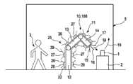
图1示出了具有根据本发明的防护装置的、布置在工作区域中的工业机器人的简化视图,和Figure 1 shows a simplified view of an industrial robot arranged in a work area with a protective device according to the invention, and
图2示出了用来说明根据本发明的用于运行防护装置的方法的框图。FIG. 2 shows a block diagram illustrating the method according to the invention for operating a safety device.
相同的部件或功能相同的部件在附图中具有相同的附图标记。Identical or functionally identical components have the same reference symbols in the figures.
具体实施方式Detailed ways
在图1中非常简化地示出了工业机器人100形式的搬运装置10。搬运装置10或者说工业机器人100具有多轴的握持装置11。握持装置11包括立柱12,在该立柱上连接有两个可运动地布置的支架13、14。在所述一个支架14的端部上示例性地布置有三个握持指15至17,利用所述握持指可以握住在图1中象征性示出的物品或者说部件1,其布置在工作台2上。A handling device 10 in the form of an industrial robot 100 is shown very simplified in FIG. 1 . The handling device 10 or the industrial robot 100 has a multi-axis handling device 11 . The holding device 11 comprises a
立柱12或支架13、14支承在未详细描述或者说示出的旋转-或摆动轴上,从而握持装置11或握持指15至17可以驶向每个位于工作空间5内的空间点。工作空间5因此形成了握持装置11的系统界限。由此特别是能实现,例如将部件1从工作台2上拿起并且运送到另一个位于工作空间5内的地点,在那里例如将部件1与其它的、未示出的部件进行安装。The
在图1中示出了这样的情况,即握持指15至17接近部件1,这通过第一路径区段18示出。在握住部件1之后,驶向了所述的在工作空间5内的所涉及的点,这通过第二路径区段19显示。两个路径区段18,19在此形成了存储在搬运装置10中的、握持装置11的运动过程或者说运动路径,其中,在运动路径上,握持装置11或握持指15至17可以以不同的速度运动。FIG. 1 shows the approach of the
搬运装置10至少在立柱12和支架13、14的区域中由吸收碰撞的外壳22围绕,其厚度这样调整或者说确定,即在可能发生与物体3、例如操作人员的碰撞的情况下,在运动路径上可以实现握持装置11的停止,而不会导致物体3受损。The handling device 10 is surrounded at least in the area of the
此外,搬运装置10包括传感器装置25,其例如具有多个单独的、带有检测区域28、29的传感器元件26、27。传感器装置25在此例如这样布置在外壳22的外侧面上,即传感器元件26、27在握持装置11运动时可以检测到所有的位于运动路径上的空间点。Furthermore, the handling device 10 includes a
作为传感器元件26、27特别应用了电容式的传感器元件26、27,其在传感器元件26、27和物体3之间相对接近的情况下将相应的信号发出给搬运装置10的控制装置30。原则上然而可以考虑用于传感器元件26、27的不同的测量原理。因此例如也可以应用基于超声波或雷达运行的传感器元件26、27。重要的仅在于,在物体3与搬运装置10发生碰撞或者说接触之前,借助于传感器元件26、27检测到或者说发现了检测区域28、29内的物体3。In particular
大体上所描述的传感器元件26、27与控制装置30共同形成了用于搬运装置10的防护装置50。现在根据图2详细说明了其功能原理:识别出,传感器元件26、27引导信号地与控制装置30相连接。在控制装置30中存储了防碰撞程序或相应的算法,其处理了由传感器元件26、27优选持续地接收的、关于在检测区域28、29内物体3存在的信号。因此在第一程序步骤52中询问,是否由传感器元件26、27通知关于在检测区域28、29中的物体3的信号。如果不是这种情况,则相应于第二程序步骤53,实施握持装置11的确定的运动过程或确定的运动路径20,也就是说,搬运装置10在其正常运行状态中工作,其中部件1被以期望的方式和方法搬运。The generally described
如果相反地,传感器元件26、27之一在第一程序步骤52中通知了在检测区域28、29内的物体3,则因此可能在另一个程序步骤54中确定了相应的传感器元件26、27。由于传感器元件26、27优选地在相同长度的时间段内产生相应的信号,则还可以例如从相应的信号强度推断出在物体3和传感器元件26、27或搬运装置10之间的相应的接近速度。此外也可能的是,从传感器元件26、27的所检测的或传输的信号中查明,物体3和握持装置11是否在运动路径20的区域中发生可能的碰撞。If, on the other hand, one of the
如果存在可能的碰撞危险,则在下一个程序步骤55中这样受控地降低握持装置11的运动速度,即,根据在物体3和运动路径20之间的当前的间距或者在物体3到运动路径20的接近速度,在可能的碰撞点中,必要时将速度降低到值零。在此重要的是,这涉及受控制的、也就是说握持装置11的运动速度的受控的降低,也就是说,控制装置30在每个时间点可以检测到握持装置11或握持指15至17的准确的位置。If there is a possible risk of collision, then in the
特别优选地设计为,握持装置11的运动速度的变化或降低根据在物体3和握持装置10之间的相应的间距或者相应的接近速度进行。这意味着,如果在物体3和握持装置10之间的间距在其运动路径上再次增大,则握持装置11的运动速度再次提高,必要时提高至相应于握持装置11的正常运行状态的额定速度。因此,一旦物体3可能与握持装置10发生碰撞危险,则发生了握持装置10的速度-或功率优化。It is particularly preferably provided that the speed of movement of the holding device 11 is changed or reduced depending on the corresponding distance between the object 3 and the holding device 10 or the corresponding approach speed. This means that if the distance between the object 3 and the holding device 10 increases again along its path of motion, the speed of movement of the holding device 11 increases again, possibly to the normal operation of the holding device 11 State rated speed. As a result, a speed or power optimization of the handling device 10 takes place as soon as the object 3 is at risk of colliding with the handling device 10 .
然而也可以设计为,在通过传感器元件26、27之一检测到一个物体时,握持装置11的运动速度受控地降低直至停止状态。一旦不再检测到物体,则运动速度重新提高到其初始值。However, it can also be provided that, when an object is detected by one of the
补充说明的是,大体上所述的防护装置50或握持装置10能以多种方式和方法改变,而不背离本发明的构思。因此特别有意义的是,在传感器元件26、27中应用了利用不同的测量原理(例如电容式工作的传感器元件27和基于超声波工作的传感器元件27)进行工作的传感器元件。此外为了提高运行安全性可以考虑的是或者有利的是,至少分别两个传感器元件26、27具有一个相同的检测区域28、29,如此使得,借助于相应的检测区域28、29监控了工作空间5中的相同的区域。此外也可能的是,握持指15至17力配合地布置或固定在支架14上,如此使得,如果例如操作者握住部件1,虽然握持指15至17可能与操作者的手相接触,然而它们在碰撞方向上设计为柔顺的或者说退让的(nachgebend),使得至少可以排除操作者严重受伤的危险。It should be added that the
Claims (10)
Applications Claiming Priority (3)
| Application Number | Priority Date | Filing Date | Title |
|---|---|---|---|
| DE102010063208.2 | 2010-12-16 | ||
| DE102010063208ADE102010063208A1 (en) | 2010-12-16 | 2010-12-16 | Method for operating a safety device for a handling device, safety device for a handling device and handling device |
| PCT/EP2011/072330WO2012080123A2 (en) | 2010-12-16 | 2011-12-09 | Method for operating a safety apparatus for a handling device, safety apparatus for a handling device, and handling device |
Publications (2)
| Publication Number | Publication Date |
|---|---|
| CN103249530Atrue CN103249530A (en) | 2013-08-14 |
| CN103249530B CN103249530B (en) | 2016-03-30 |
Family
ID=45491532
Family Applications (1)
| Application Number | Title | Priority Date | Filing Date |
|---|---|---|---|
| CN201180060781.8AActiveCN103249530B (en) | 2010-12-16 | 2011-12-09 | Method for operating a guard for a handling device, guard and handling device |
Country Status (7)
| Country | Link |
|---|---|
| US (1) | US9296106B2 (en) |
| EP (1) | EP2651608B1 (en) |
| JP (1) | JP5988993B2 (en) |
| CN (1) | CN103249530B (en) |
| DE (1) | DE102010063208A1 (en) |
| DK (1) | DK2651608T3 (en) |
| WO (1) | WO2012080123A2 (en) |
Cited By (14)
| Publication number | Priority date | Publication date | Assignee | Title |
|---|---|---|---|---|
| CN103386684A (en)* | 2013-08-21 | 2013-11-13 | 福州大学 | Device and design method for preventing robot from generating accidental collision |
| CN104440954A (en)* | 2014-10-30 | 2015-03-25 | 青岛立邦达机器人系统有限公司 | Conveying robot anti-collision safety protection system |
| CN105082184A (en)* | 2015-07-13 | 2015-11-25 | 苏州铂电自动化科技有限公司 | Safety protection device for industrial robot |
| CN105291115A (en)* | 2014-07-24 | 2016-02-03 | 库卡罗伯特有限公司 | Method and means for designing and/or operating a robot |
| CN106271114A (en)* | 2016-10-10 | 2017-01-04 | 山东科技大学 | Laser processing device |
| CN106794578A (en)* | 2014-06-03 | 2017-05-31 | 软银机器人欧洲公司 | The security of humanoid robot |
| CN107407919A (en)* | 2015-03-04 | 2017-11-28 | Abb股份公司 | Safety control system and method of operating the safety control system |
| CN107756396A (en)* | 2016-08-15 | 2018-03-06 | 发那科株式会社 | Robot system |
| CN109304735A (en)* | 2017-07-26 | 2019-02-05 | Fogale 纳米技术公司 | Robot equipped with protective potential-referenced wall and capacitance detection |
| KR102001569B1 (en) | 2019-02-26 | 2019-07-18 | 윤양수 | Air pad for protection of machinery |
| CN110168333A (en)* | 2017-03-21 | 2019-08-23 | 住友理工株式会社 | Sensor device |
| TWI699636B (en)* | 2019-05-21 | 2020-07-21 | 華邦電子股份有限公司 | Collaborative robot control system and method |
| CN113557108A (en)* | 2019-03-28 | 2021-10-26 | 欧姆龙株式会社 | Control system, control method, and control unit |
| CN114012706A (en)* | 2021-11-12 | 2022-02-08 | 佛山市南海区广工大数控装备协同创新研究院 | A robust gripping method and gripping system for moving objects based on velocity modulation |
Families Citing this family (39)
| Publication number | Priority date | Publication date | Assignee | Title |
|---|---|---|---|---|
| US9643316B2 (en) | 2009-10-27 | 2017-05-09 | Battelle Memorial Institute | Semi-autonomous multi-use robot system and method of operation |
| US10095991B2 (en)* | 2012-01-13 | 2018-10-09 | Mitsubishi Electric Corporation | Risk measurement system |
| WO2013140579A1 (en)* | 2012-03-22 | 2013-09-26 | 株式会社安川電機 | Work robot and robot system |
| DE102013212887B4 (en) | 2012-10-08 | 2019-08-01 | Deutsches Zentrum für Luft- und Raumfahrt e.V. | Method for controlling a robot device, robot device, computer program product and controller |
| DE102013020697B4 (en)* | 2013-12-04 | 2023-07-06 | Kuka Roboter Gmbh | Method and control means for controlling a robot |
| DE102013021387B4 (en)* | 2013-12-13 | 2019-09-12 | Daimler Ag | Robot and method for operating such a robot |
| DE102014114596B4 (en) | 2014-01-28 | 2018-09-06 | Franka Emika Gmbh | Control of a robot arm |
| US9452531B2 (en) | 2014-02-04 | 2016-09-27 | Microsoft Technology Licensing, Llc | Controlling a robot in the presence of a moving object |
| CH709347A2 (en)* | 2014-03-10 | 2015-09-15 | Tecan Trading Ag | A method for path finding in an automated handling system and handling system with corresponding control module for pathfinding. |
| JP6375728B2 (en)* | 2014-07-01 | 2018-08-22 | 富士電機株式会社 | Safety control device and safety control system |
| AT516097B1 (en)* | 2014-07-03 | 2016-09-15 | Blue Danube Robotics Gmbh | Protection method and protective device for handling equipment |
| DE102014012563B4 (en)* | 2014-08-04 | 2018-10-25 | Abb Schweiz Ag | Proximity sensor system for a robot |
| EP3020514B1 (en)* | 2014-11-17 | 2023-10-11 | KRONES Aktiengesellschaft | Handling device and method for handling items |
| DE102015108010B3 (en)* | 2015-05-20 | 2016-06-02 | Cavos Bagatelle Verwaltungs Gmbh & Co. Kg | Controlling and controlling actuators of a robot taking into account ambient contacts |
| DE102015112656A1 (en) | 2015-07-31 | 2017-02-02 | Sick Ag | Distance sensor |
| TWI564128B (en)* | 2015-11-17 | 2017-01-01 | 和碩聯合科技股份有限公司 | Collision-avoidance detecting device, corresponding control method and applicable robotic arm thereof |
| US10065316B2 (en)* | 2016-02-05 | 2018-09-04 | Rethink Robotics, Inc. | Systems and methods for safe robot operation |
| DE102016004902A1 (en)* | 2016-04-22 | 2017-10-26 | Kuka Roboter Gmbh | Monitoring a robot |
| DE102016222016B4 (en)* | 2016-11-09 | 2021-09-02 | Kuka Deutschland Gmbh | Method for monitoring a robot and control unit |
| JP6879736B2 (en)* | 2016-12-28 | 2021-06-02 | 川崎重工業株式会社 | Robot system |
| JP6496335B2 (en)* | 2017-03-03 | 2019-04-03 | ファナック株式会社 | Robot system |
| DK201700203A1 (en)* | 2017-03-23 | 2018-11-27 | Mrr | Safety system for collaborative robot |
| US10766140B2 (en) | 2017-04-13 | 2020-09-08 | Battelle Memorial Institute | Teach mode collision avoidance system and method for industrial robotic manipulators |
| FR3070022B1 (en)* | 2017-08-10 | 2020-11-06 | Fogale Nanotech | CAPACITIVE DRESSING ELEMENT FOR ROBOT, ROBOT EQUIPPED WITH SUCH A DRESSING ELEMENT |
| JP6608894B2 (en)* | 2017-09-27 | 2019-11-20 | ファナック株式会社 | Robot system |
| CN111546381A (en)* | 2017-10-24 | 2020-08-18 | 孙立民 | Industrial robot anticollision gripping apparatus device |
| DE102018203049A1 (en) | 2018-03-01 | 2019-09-05 | Bayerische Motoren Werke Aktiengesellschaft | Collision detection device for detecting a collision of a robot device with an object and method for operating such a collision detection device |
| IT201800003462A1 (en)* | 2018-03-12 | 2019-09-12 | Cover Sistemi S R L | A ROBOT |
| DE102018206019B4 (en)* | 2018-04-19 | 2021-01-21 | Kuka Deutschland Gmbh | Robot system and method for operating the robot system |
| DE102018208813A1 (en) | 2018-06-05 | 2019-12-05 | Robert Bosch Gmbh | Safety device for a handling device, industrial robot and method for operating a safety device |
| DE102018133472B3 (en)* | 2018-12-21 | 2020-03-12 | Franka Emika Gmbh | Motion monitoring of a robot manipulator |
| JP7064458B2 (en)* | 2019-02-20 | 2022-05-10 | Skソリューション株式会社 | Robot control method |
| DE102019110882B4 (en)* | 2019-04-26 | 2021-04-01 | Sick Ag | Securing a moving machine part |
| US11123870B2 (en)* | 2019-09-27 | 2021-09-21 | HighRes Biosolutions, Inc. | Robotic transport system and method therefor |
| JP2021091060A (en)* | 2019-12-12 | 2021-06-17 | セイコーエプソン株式会社 | Control method and robot system |
| KR102855324B1 (en)* | 2020-01-09 | 2025-09-05 | 삼성전자주식회사 | Robot control system and method |
| DE102021102509A1 (en) | 2021-02-03 | 2022-08-04 | Deutsches Zentrum für Luft- und Raumfahrt e.V. | Process for the compliant control of a robot |
| DE102022205357A1 (en) | 2022-05-30 | 2023-11-30 | Robert Bosch Gesellschaft mit beschränkter Haftung | Method for checking a movable component of a technical device |
| CN117585447B (en)* | 2024-01-17 | 2024-05-17 | 宁德时代新能源科技股份有限公司 | Conveying equipment, battery production line and control method of conveying equipment |
Citations (6)
| Publication number | Priority date | Publication date | Assignee | Title |
|---|---|---|---|---|
| JPH0811085A (en)* | 1994-06-28 | 1996-01-16 | Toyota Motor Corp | robot |
| JPH11226889A (en)* | 1998-02-16 | 1999-08-24 | Shinko Electric Co Ltd | Work device |
| EP1323503A2 (en)* | 2001-12-19 | 2003-07-02 | KUKA Roboter GmbH | Device and method for securing an apparatus with freely movable parts |
| CN1749135A (en)* | 2004-09-16 | 2006-03-22 | 发那科株式会社 | Handling robot system |
| DE102007062245A1 (en)* | 2007-12-21 | 2009-06-25 | Robert Bosch Gmbh | Collision detection device for robot arm in automatic production process, has tube and/or hose shaped, sectional, flexible storage units filled with medium and attached with pressure sensors, and control device detecting collision |
| WO2010072193A1 (en)* | 2008-12-24 | 2010-07-01 | Gottfried Wilhelm Leibniz Universität Hannover | Securing apparatus and method for operating a multi-member machine |
Family Cites Families (15)
| Publication number | Priority date | Publication date | Assignee | Title |
|---|---|---|---|---|
| ATE43277T1 (en)* | 1984-04-09 | 1989-06-15 | Elektroniktechnologie Get | ELECTRONIC WARNING AND MONITORING DEVICE FOR HANDLING EQUIPMENT. |
| US4821584A (en)* | 1988-03-15 | 1989-04-18 | The United States Of America As Represented By The United States Department Of Energy | Piezoelectric film load cell robot collision detector |
| FR2663105A1 (en) | 1990-06-11 | 1991-12-13 | Inst Nat Sciences Appliq Lyon | PROTECTION DEVICE WITH CAPACITIVE SENSOR FOR INDUSTRIAL ROBOT OR SIMILAR MACHINE. |
| JP2812582B2 (en)* | 1991-05-21 | 1998-10-22 | 株式会社日立製作所 | Industrial robot controller |
| US5166679A (en) | 1991-06-06 | 1992-11-24 | The United States Of America As Represented By The Administrator Of The National Aeronautics & Space Administration | Driven shielding capacitive proximity sensor |
| JP4023340B2 (en)* | 2003-03-06 | 2007-12-19 | トヨタ自動車株式会社 | Vehicle collision prevention device |
| DE212005000036U1 (en)* | 2004-06-24 | 2007-02-15 | Abb Ab | Device for controlling a robot by a wireless programming handset unit |
| JP3907649B2 (en) | 2004-09-02 | 2007-04-18 | ファナック株式会社 | Interference prevention control device between robots |
| US20060178775A1 (en)* | 2005-02-04 | 2006-08-10 | George Zhang | Accelerometer to monitor movement of a tool assembly attached to a robot end effector |
| US7533798B2 (en)* | 2006-02-23 | 2009-05-19 | Rockwell Automation Technologies, Inc. | Data acquisition and processing system for risk assessment |
| DE102007041097A1 (en)* | 2006-09-04 | 2008-03-06 | Robert Bosch Gmbh | Machine tool monitoring device |
| JP5007167B2 (en)* | 2007-07-09 | 2012-08-22 | Udトラックス株式会社 | Vehicle travel control device |
| JP5017379B2 (en)* | 2008-01-22 | 2012-09-05 | パナソニック株式会社 | Robot arm |
| JP4495252B2 (en)* | 2008-07-09 | 2010-06-30 | パナソニック株式会社 | Route risk evaluation device, route risk evaluation method and program |
| WO2010063319A1 (en)* | 2008-12-03 | 2010-06-10 | Abb Research Ltd. | A robot safety system and a method |
- 2010
- 2010-12-16DEDE102010063208Apatent/DE102010063208A1/ennot_activeCeased
- 2011
- 2011-12-09DKDK11808609.9Tpatent/DK2651608T3/enactive
- 2011-12-09USUS13/994,460patent/US9296106B2/enactiveActive
- 2011-12-09WOPCT/EP2011/072330patent/WO2012080123A2/enactiveApplication Filing
- 2011-12-09EPEP11808609.9Apatent/EP2651608B1/enactiveActive
- 2011-12-09CNCN201180060781.8Apatent/CN103249530B/enactiveActive
- 2011-12-09JPJP2013543663Apatent/JP5988993B2/enactiveActive
Patent Citations (6)
| Publication number | Priority date | Publication date | Assignee | Title |
|---|---|---|---|---|
| JPH0811085A (en)* | 1994-06-28 | 1996-01-16 | Toyota Motor Corp | robot |
| JPH11226889A (en)* | 1998-02-16 | 1999-08-24 | Shinko Electric Co Ltd | Work device |
| EP1323503A2 (en)* | 2001-12-19 | 2003-07-02 | KUKA Roboter GmbH | Device and method for securing an apparatus with freely movable parts |
| CN1749135A (en)* | 2004-09-16 | 2006-03-22 | 发那科株式会社 | Handling robot system |
| DE102007062245A1 (en)* | 2007-12-21 | 2009-06-25 | Robert Bosch Gmbh | Collision detection device for robot arm in automatic production process, has tube and/or hose shaped, sectional, flexible storage units filled with medium and attached with pressure sensors, and control device detecting collision |
| WO2010072193A1 (en)* | 2008-12-24 | 2010-07-01 | Gottfried Wilhelm Leibniz Universität Hannover | Securing apparatus and method for operating a multi-member machine |
Cited By (19)
| Publication number | Priority date | Publication date | Assignee | Title |
|---|---|---|---|---|
| CN103386684B (en)* | 2013-08-21 | 2016-02-24 | 福州大学 | A kind of device and method for designing preventing robot generation accident collision |
| CN103386684A (en)* | 2013-08-21 | 2013-11-13 | 福州大学 | Device and design method for preventing robot from generating accidental collision |
| CN106794578A (en)* | 2014-06-03 | 2017-05-31 | 软银机器人欧洲公司 | The security of humanoid robot |
| CN105291115B (en)* | 2014-07-24 | 2018-04-03 | 库卡罗伯特有限公司 | For planning and/or the method and apparatus of operation robot |
| CN105291115A (en)* | 2014-07-24 | 2016-02-03 | 库卡罗伯特有限公司 | Method and means for designing and/or operating a robot |
| CN104440954A (en)* | 2014-10-30 | 2015-03-25 | 青岛立邦达机器人系统有限公司 | Conveying robot anti-collision safety protection system |
| CN107407919B (en)* | 2015-03-04 | 2020-08-25 | Abb股份公司 | Safety control system and method for operating a safety control system |
| CN107407919A (en)* | 2015-03-04 | 2017-11-28 | Abb股份公司 | Safety control system and method of operating the safety control system |
| CN105082184A (en)* | 2015-07-13 | 2015-11-25 | 苏州铂电自动化科技有限公司 | Safety protection device for industrial robot |
| CN107756396A (en)* | 2016-08-15 | 2018-03-06 | 发那科株式会社 | Robot system |
| CN106271114A (en)* | 2016-10-10 | 2017-01-04 | 山东科技大学 | Laser processing device |
| CN110168333A (en)* | 2017-03-21 | 2019-08-23 | 住友理工株式会社 | Sensor device |
| CN109304735A (en)* | 2017-07-26 | 2019-02-05 | Fogale 纳米技术公司 | Robot equipped with protective potential-referenced wall and capacitance detection |
| CN109304735B (en)* | 2017-07-26 | 2022-01-25 | Fogale 纳米技术公司 | Robot equipped with wall and capacitance detection device with reference to protection potential |
| KR102001569B1 (en) | 2019-02-26 | 2019-07-18 | 윤양수 | Air pad for protection of machinery |
| CN113557108A (en)* | 2019-03-28 | 2021-10-26 | 欧姆龙株式会社 | Control system, control method, and control unit |
| US12023813B2 (en) | 2019-03-28 | 2024-07-02 | Omron Corporation | Control system, control method, and control unit |
| TWI699636B (en)* | 2019-05-21 | 2020-07-21 | 華邦電子股份有限公司 | Collaborative robot control system and method |
| CN114012706A (en)* | 2021-11-12 | 2022-02-08 | 佛山市南海区广工大数控装备协同创新研究院 | A robust gripping method and gripping system for moving objects based on velocity modulation |
Also Published As
| Publication number | Publication date |
|---|---|
| CN103249530B (en) | 2016-03-30 |
| WO2012080123A2 (en) | 2012-06-21 |
| EP2651608A2 (en) | 2013-10-23 |
| US9296106B2 (en) | 2016-03-29 |
| DE102010063208A1 (en) | 2012-06-21 |
| EP2651608B1 (en) | 2023-02-08 |
| WO2012080123A3 (en) | 2012-09-07 |
| JP5988993B2 (en) | 2016-09-07 |
| DK2651608T3 (en) | 2023-04-24 |
| JP2014501179A (en) | 2014-01-20 |
| US20140025204A1 (en) | 2014-01-23 |
Similar Documents
| Publication | Publication Date | Title |
|---|---|---|
| CN103249530B (en) | Method for operating a guard for a handling device, guard and handling device | |
| US9475200B2 (en) | Safety device for a handling apparatus, in particular an industrial robot, and method for operating the safety device | |
| CN104428107B (en) | The method that robot arranges and is used for controlling robot | |
| EP2364243B1 (en) | A robot safety system and a method | |
| US11524373B2 (en) | Device for the automatic manufacture of screw connections by means of a screw | |
| JP2017030081A (en) | Industrial robot system and control method for same | |
| CN109551517B (en) | Robot system | |
| CN112476438A (en) | Mechanical arm obstacle avoidance method and device, mechanical arm and robot | |
| JP4788767B2 (en) | Travel equipment for self-propelled equipment | |
| CN112693421B (en) | Pedestrian protection device and control method thereof | |
| CN107813308A (en) | A kind of human computer cooperation system of robot | |
| KR20120140545A (en) | A system for protecting a walker of vehicle | |
| US11511433B2 (en) | Collision-detection device for gripper systems and method for detecting a collision | |
| US10875180B2 (en) | Robot system | |
| CN109254295B (en) | Anti-collision detection device, method and equipment | |
| TWI564128B (en) | Collision-avoidance detecting device, corresponding control method and applicable robotic arm thereof | |
| JP2019171538A (en) | Controller and control method of cooperation robot | |
| CN108621205A (en) | Anti-pinch method of cooperative type robot arm | |
| KR101968751B1 (en) | Collision sensing apparatus, end effector having the same, robot, and collision detection method using the same | |
| CN207155801U (en) | A kind of robot | |
| CN220398411U (en) | Safety airbag is with leading steel wire joint detection frock | |
| CN113276097B (en) | A Stewart six-degree-of-freedom electric motion platform with protection device | |
| JP2009285775A (en) | Technology for controlling device in which part including operation interface is movable with respect to operator | |
| US20230202045A1 (en) | Robot System | |
| KR20120053098A (en) | Robot control system |
Legal Events
| Date | Code | Title | Description |
|---|---|---|---|
| C06 | Publication | ||
| PB01 | Publication | ||
| C10 | Entry into substantive examination | ||
| SE01 | Entry into force of request for substantive examination | ||
| C14 | Grant of patent or utility model | ||
| GR01 | Patent grant |