CN103248447A - Wavelength division multiplexing passive optical network system - Google Patents
Wavelength division multiplexing passive optical network systemDownload PDFInfo
- Publication number
- CN103248447A CN103248447ACN2012100290490ACN201210029049ACN103248447ACN 103248447 ACN103248447 ACN 103248447ACN 2012100290490 ACN2012100290490 ACN 2012100290490ACN 201210029049 ACN201210029049 ACN 201210029049ACN 103248447 ACN103248447 ACN 103248447A
- Authority
- CN
- China
- Prior art keywords
- wavelength
- submodule
- photodetector
- light wave
- detection
- Prior art date
- Legal status (The legal status is an assumption and is not a legal conclusion. Google has not performed a legal analysis and makes no representation as to the accuracy of the status listed.)
- Pending
Links
Images


Landscapes
- Optical Communication System (AREA)
Abstract
Translated fromChinese
Description
Translated fromChinese技术领域technical field
本发明涉及光通信技术领域,特别涉及一种波分复用无源光网络系统。The invention relates to the technical field of optical communication, in particular to a wavelength division multiplexing passive optical network system.
背景技术Background technique
在当前全业务运营和网络融合的背景下,高带宽应用如高清和3D视频为主的高清流媒体业务,交互式的网络游戏以及视频会议,IPTV等对网络的接入带宽提出了更高的要求,当前主流的时分复用无源光纤网络(TDM PON)接入方式已经不能有效满足需求。为了解决当前TDM PON技术存在的传输距离与系统容量的限制,波分复用无源光纤网络(WDM PON)技术被认为是最有前景和希望的下一代PON技术。与TDM PON不同,WDM PON采用波分复用的方式对不同波长进行复用,为每个光网络单元(ONU)提供了一个独享的波长资源来进行数据传输,从而极大的提高了ONU端的带宽,扩展了PON系统的容量。Under the background of current full-service operation and network integration, high-bandwidth applications such as high-definition and 3D video-based high-definition streaming media services, interactive online games, video conferencing, and IPTV have put forward higher requirements for network access bandwidth. The current mainstream time-division multiplexing passive optical network (TDM PON) access method can no longer effectively meet the requirements. In order to solve the limitation of transmission distance and system capacity in current TDM PON technology, wavelength division multiplexing passive optical network (WDM PON) technology is considered to be the most promising and hopeful next-generation PON technology. Different from TDM PON, WDM PON uses wavelength division multiplexing to multiplex different wavelengths, providing each optical network unit (ONU) with an exclusive wavelength resource for data transmission, thus greatly improving the ONU End bandwidth, expanding the capacity of the PON system.
WDM PON由光线路终端(OLT)、远端节点(RN)和光网络单元组成。下行传输时,OLT使用多波长光源,将数据加载到载波上,发送到ONU。通过波分复用(WDM)的方式将多波长信号复合到一根光纤上传输,在RN处解复用,并根据波长把信号分配给目的ONU。上传数据时,每个ONU使用一个特定的波长,各ONU可以同时接入。上传信号在RN处复用到一根光纤上,传到OLT接收端,经WDM(或阵列波导光栅AWG)解复用器分路,由接收机阵列接收。由于每个ONU通过不同波长与OLT进行通信,因此称ONU与OLT之间是虚拟的点对点双向传输链路。WDM PON consists of Optical Line Terminal (OLT), Remote Node (RN) and Optical Network Unit. During downlink transmission, the OLT uses a multi-wavelength light source to load data onto the carrier and send it to the ONU. Multi-wavelength signals are multiplexed to one optical fiber for transmission through wavelength division multiplexing (WDM), demultiplexed at the RN, and the signals are distributed to the destination ONU according to the wavelength. When uploading data, each ONU uses a specific wavelength, and each ONU can access at the same time. The uploaded signal is multiplexed on an optical fiber at the RN, transmitted to the receiving end of the OLT, demultiplexed by the WDM (or arrayed waveguide grating AWG) demultiplexer, and received by the receiver array. Since each ONU communicates with the OLT through different wavelengths, it is called a virtual point-to-point bidirectional transmission link between the ONU and the OLT.
在WDM PON技术中,所有的ONU发射与接收的信号的波长必须要与之相邻的ONU的信号波长不同,为了能进行设备的大众化生产和设备的简易管理与维护,降低WDM PON系统的成本,就必须要求每个ONU的设备都是一模一样的,因此需要设计出无色的ONU。当前实现无色ONU的方法有两种,一种是基于反射型半导体光放大器(RSOA),另外一种是基于多纵模半导体激光器(FP-LD)。前者虽研究较广,但存在下述不利因素:通常需要种子光选频,RSOA调制带宽小限制调制速率及传输距离,系统成本高。后者虽然研究较少,但存在FP-LD成熟、调制带宽大且可支持远距离传输、成本底等优点,而无法通过硬件结构自动实现ONU的上行光波的波长选择与锁模,导致极大的增加了控制的复杂度。In WDM PON technology, the wavelengths of signals transmitted and received by all ONUs must be different from those of adjacent ONUs. In order to facilitate the mass production of equipment and easy management and maintenance of equipment, the cost of WDM PON systems can be reduced. , it is necessary to require the equipment of each ONU to be exactly the same, so it is necessary to design a colorless ONU. There are currently two methods for realizing a colorless ONU, one is based on a reflective semiconductor optical amplifier (RSOA), and the other is based on a multi-longitudinal mode semiconductor laser (FP-LD). Although the former has been widely studied, it has the following disadvantages: it usually requires seed light frequency selection, the small bandwidth of RSOA modulation limits the modulation rate and transmission distance, and the system cost is high. Although the latter has less research, it has the advantages of mature FP-LD, large modulation bandwidth, long-distance transmission support, and low cost, but it cannot automatically realize the wavelength selection and mode-locking of the upstream optical wave of the ONU through the hardware structure, resulting in huge increases the complexity of the control.
发明内容Contents of the invention
(一)要解决的技术问题(1) Technical problems to be solved
本发明要解决的技术问题是:如何通过硬件结构自动实现ONU的上行光波的波长选择与锁模,以降低控制的复杂度。The technical problem to be solved by the present invention is: how to automatically realize the wavelength selection and mode locking of the upstream optical wave of the ONU through the hardware structure, so as to reduce the complexity of control.
(二)技术方案(2) Technical solution
为解决上述技术问题,本发明提供了一种波分复用无源光网络系统,所述系统包括:依次连接的光线路终端、远端节点和m个光网络单元,所述m为大于零的整数,各个光网络单元均包括:第一环形器、下行波长探测子模块、探测及调谐控制电路和反馈锁定子模块,所述第一环形器分别与所述远端节点、下行波长探测子模块和反馈锁定子模块连接,所述探测及调谐控制电路分别与所述下行波长探测子模块和反馈锁定子模块连接,In order to solve the above technical problems, the present invention provides a wavelength division multiplexing passive optical network system, said system comprising: sequentially connected optical line terminals, remote nodes, and m optical network units, where m is greater than zero Each optical network unit includes: a first circulator, a downlink wavelength detection submodule, a detection and tuning control circuit, and a feedback locking submodule, and the first circulator is connected to the remote node and the downlink wavelength detection submodule respectively. The module is connected to the feedback locking submodule, and the detection and tuning control circuit is respectively connected to the downlink wavelength detection submodule and the feedback locking submodule,
所述下行波长探测子模块,用于在所述探测及调谐控制电路的控制下,对由所述光线路终端所传送来的下行光波进行探测,以获得所述下行光波的波长;The downlink wavelength detection sub-module is used to detect the downlink light wave transmitted by the optical line terminal under the control of the detection and tuning control circuit, so as to obtain the wavelength of the downlink light wave;
所述反馈锁定子模块,用于在所述探测及调谐控制电路的控制下,根据所述下行光波的波长来选择和锁定上行光波的波长。The feedback locking sub-module is used to select and lock the wavelength of the uplink light wave according to the wavelength of the downlink light wave under the control of the detection and tuning control circuit.
优选地,所述下行波长探测子模块包括:波长可调谐光电探测器,所述探测及调谐控制电路与所述波长可调谐光电探测器连接,所述波长可调谐光电探测器包括:半导体基质F-P腔窄带滤波器和与所述半导体基质F-P腔窄带滤波器键合的p-i-n光电探测器,所述半导体基质基底F-P腔窄带滤波器用于对接收的下行光波进行滤波,并将透射后的光信息号传输至所述p-i-n光电探测器的吸收层,以获得所述下行光波的波长。Preferably, the downlink wavelength detection sub-module includes: a wavelength tunable photodetector, the detection and tuning control circuit is connected to the wavelength tunable photodetector, and the wavelength tunable photodetector includes: a semiconductor substrate F-P A cavity narrow-band filter and a p-i-n photodetector bonded to the semiconductor substrate F-P cavity narrow-band filter, the semiconductor substrate F-P cavity narrow-band filter is used to filter the received downlink light wave and transmit the transmitted optical information signal transmitted to the absorbing layer of the p-i-n photodetector to obtain the wavelength of the downgoing light wave.
优选地,所述F-P腔窄带滤波器为GaAs基底F-P腔窄带滤波器,所述p-i-n光电探测器为InP基底光电探测器。Preferably, the F-P cavity narrowband filter is a GaAs substrate F-P cavity narrowband filter, and the p-i-n photodetector is an InP substrate photodetector.
优选地,所述波长可调谐光电探测器还包括自聚焦棒,所述自聚焦棒用于将所述待测光信号耦合进所述半导体基质F-P腔窄带滤波器。Preferably, the wavelength tunable photodetector further includes a self-focusing rod for coupling the optical signal to be measured into the semiconductor substrate F-P cavity narrow-band filter.
优选地,下行波长探测子模块还包括:非均分光耦合器,所述非均分光耦合器设于所述第一环形器和所述波长可调谐光电探测器之间,用于将部分的下行光波传输至所述波长可调谐光电探测器。Preferably, the downlink wavelength detection sub-module further includes: a non-uniform optical coupler, the non-uniform optical coupler is arranged between the first circulator and the wavelength tunable photodetector, and is used for part of the downlink Light waves are transmitted to the wavelength tunable photodetector.
优选地,所述非均分光耦合器将小于10%的下行光波传输至所述波长可调谐光电探测器。Preferably, the non-uniform optical coupler transmits less than 10% of the downlink light waves to the wavelength tunable photodetector.
优选地,所述反馈锁定子模块包括:依次连接的反馈环、可调谐半导体滤波器、以及多纵模半导体激光器,所述反馈环与所述第一环形器连接,所述探测及调谐控制电路与所述可调谐半导体滤波器连接,所述可调谐半导体滤波器在所述探测及调谐控制电路的控制下,根据所述下行光波的波长来选择和锁定所述可调谐半导体滤波器可通过的上行光波的波长。Preferably, the feedback locking sub-module includes: a sequentially connected feedback loop, a tunable semiconductor filter, and a multi-longitudinal mode semiconductor laser, the feedback loop is connected to the first circulator, and the detection and tuning control circuit Connected with the tunable semiconductor filter, under the control of the detection and tuning control circuit, the tunable semiconductor filter selects and locks the light wave that the tunable semiconductor filter can pass through according to the wavelength of the downlink light wave. The wavelength of the upstream light wave.
优选地,所述光线路终端包括:第二环形器、上行接收模块和下行发送模块,所述第二环形器分别与上行接收模块和下行发送模块连接。Preferably, the optical line terminal includes: a second circulator, an uplink receiving module and a downlink sending module, and the second circulator is connected to the uplink receiving module and the downlink sending module respectively.
优选地,所述上行接收模块包括:m个光电探测器子模块、以及与所述m个光电探测器子模块分别连接的阵列波导光栅。Preferably, the uplink receiving module includes: m photodetector submodules, and arrayed waveguide gratings respectively connected to the m photodetector submodules.
优选地,所述下行发送模块包括:m个发送激光器子模块、以及与所述m个发送激光器子模块分别连接的阵列波导光栅。Preferably, the downlink sending module includes: m sending laser sub-modules, and arrayed waveguide gratings respectively connected to the m sending laser sub-modules.
(三)有益效果(3) Beneficial effects
本发明通过硬件结构自动实现ONU的上行光波的波长选择与锁模,降低了控制的复杂度。The invention automatically realizes the wavelength selection and mode locking of the uplink light wave of the ONU through the hardware structure, thereby reducing the complexity of control.
附图说明Description of drawings
图1是按照本发明一种实施方式的波分复用无源光网络系统的结构示意图;Fig. 1 is a schematic structural diagram of a wavelength division multiplexing passive optical network system according to an embodiment of the present invention;
图2是图1所示的波分复用无源光网络系统中的波长可调谐光电探测器的结构示意图;Fig. 2 is a schematic structural diagram of a wavelength tunable photodetector in the wavelength division multiplexing passive optical network system shown in Fig. 1;
图3是图2所示的波长可调谐光电探测器的微结构示意图;Fig. 3 is a schematic diagram of the microstructure of the wavelength tunable photodetector shown in Fig. 2;
图4是图1所示的波分复用无源光网络系统中的可调谐半导体滤波器的结构示意图;Fig. 4 is a schematic structural diagram of a tunable semiconductor filter in the wavelength division multiplexing passive optical network system shown in Fig. 1;
图5是图4所示的可调谐半导体滤波器的微结构示意图。FIG. 5 is a schematic diagram of the microstructure of the tunable semiconductor filter shown in FIG. 4 .
具体实施方式Detailed ways
下面结合附图和实施例,对本发明的具体实施方式作进一步详细描述。以下实施例用于说明本发明,但不用来限制本发明的范围。The specific implementation manners of the present invention will be further described in detail below in conjunction with the accompanying drawings and embodiments. The following examples are used to illustrate the present invention, but are not intended to limit the scope of the present invention.
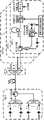
图1是按照本发明一种实施方式的波分复用无源光网络系统的结构示意图;参照图1,所述系统包括:依次连接的光线路终端(即图中的“OLT”)、远端节点(即图中的“RN”)和m个光网络单元(即图中的“ONU1”、“ONU2”......“ONUm”),所述m为大于零的整数,各个光网络单元均包括:第一环形器、下行波长探测子模块、探测及调谐控制电路和反馈锁定子模块,所述第一环形器分别与所述远端节点、下行波长探测子模块(图中未示出)和反馈锁定子模块(图中未示出)连接,所述探测及调谐控制电路分别与所述下行波长探测子模块和反馈锁定子模块连接,Fig. 1 is a schematic structural diagram of a wavelength division multiplexing passive optical network system according to an embodiment of the present invention; referring to Fig. 1, the system includes: sequentially connected optical line terminals (ie "OLT" in the figure), remote An end node (that is, "RN" in the figure) and m optical network units (that is, "ONU1 ", "ONU2 "..."ONUm " in the figure), where m is greater than zero Integer, each optical network unit includes: a first circulator, a downlink wavelength detection submodule, a detection and tuning control circuit, and a feedback locking submodule, the first circulator is connected to the remote node and the downlink wavelength detection submodule respectively (not shown in the figure) is connected to the feedback locking submodule (not shown in the figure), and the detection and tuning control circuit is respectively connected to the downlink wavelength detection submodule and the feedback locking submodule,
所述下行波长探测子模块,用于在所述探测及调谐控制电路的控制下,对由所述光线路终端所传送来的下行光波进行探测,以获得所述下行光波的波长;The downlink wavelength detection sub-module is used to detect the downlink light wave transmitted by the optical line terminal under the control of the detection and tuning control circuit, so as to obtain the wavelength of the downlink light wave;
所述反馈锁定子模块,用于在所述探测及调谐控制电路的控制下,根据所述下行光波的波长来选择和锁定上行光波的波长。The feedback locking sub-module is used to select and lock the wavelength of the uplink light wave according to the wavelength of the downlink light wave under the control of the detection and tuning control circuit.
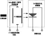
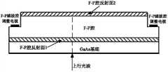
参照图2~3,优选地,所述下行波长探测子模块包括:波长可调谐光电探测器,所述探测及调谐控制电路与所述波长可调谐光电探测器连接,所述波长可调谐光电探测器包括:半导体基质F-P腔窄带滤波器和与所述半导体基质F-P腔窄带滤波器键合的p-i-n光电探测器,所述半导体基质基底F-P腔窄带滤波器用于对接收的下行光波进行滤波,并将透射后的光信息号传输至所述p-i-n光电探测器的吸收层,以获得所述下行光波的波长,所述半导体基质基底F-P腔窄带滤波器的滤波波长随加载的F-P滤波腔调整电极上的电压增加而变化。2-3, preferably, the downlink wavelength detection sub-module includes: a wavelength tunable photodetector, the detection and tuning control circuit is connected to the wavelength tunable photodetector, and the wavelength tunable photodetector The device includes: a semiconductor substrate F-P cavity narrowband filter and a p-i-n photodetector bonded to the semiconductor substrate F-P cavity narrowband filter, the semiconductor substrate F-P cavity narrowband filter is used to filter the received downlink light wave, and The transmitted optical information signal is transmitted to the absorbing layer of the p-i-n photodetector to obtain the wavelength of the downlink light wave, and the filtering wavelength of the F-P cavity narrowband filter on the semiconductor matrix substrate is adjusted with the loaded F-P filter cavity on the electrode changes with increasing voltage.
优选地,所述F-P腔窄带滤波器为GaAs基底F-P腔窄带滤波器,所述p-i-n光电探测器为InP基底光电探测器。Preferably, the F-P cavity narrowband filter is a GaAs substrate F-P cavity narrowband filter, and the p-i-n photodetector is an InP substrate photodetector.
优选地,所述波长可调谐光电探测器还包括自聚焦棒,所述自聚焦棒用于将所述待测光信号耦合进所述半导体基质F-P腔窄带滤波器。Preferably, the wavelength tunable photodetector further includes a self-focusing rod for coupling the optical signal to be measured into the semiconductor substrate F-P cavity narrow-band filter.
优选地,下行波长探测子模块还包括:非均分光耦合器,所述非均分光耦合器设于所述第一环形器和所述波长可调谐光电探测器之间,用于将部分的下行光波传输至所述波长可调谐光电探测器。Preferably, the downlink wavelength detection sub-module further includes: a non-uniform optical coupler, the non-uniform optical coupler is arranged between the first circulator and the wavelength tunable photodetector, and is used for part of the downlink Light waves are transmitted to the wavelength tunable photodetector.
为获得更为精确的结果,减小对下行光波的信号干扰,优选地,所述非均分光耦合器将小于10%的下行光波传输至所述波长可调谐光电探测器。In order to obtain more accurate results and reduce signal interference on downlink light waves, preferably, the non-uniform optical coupler transmits less than 10% of downlink light waves to the wavelength-tunable photodetector.
参照图1,优选地,所述反馈锁定子模块包括:依次连接的反馈环、可调谐半导体滤波器、以及多纵模半导体激光器(FP-LD),所述反馈环与所述第一环形器连接,所述探测及调谐控制电路与所述可调谐半导体滤波器连接,参照图4~5,所述可调谐半导体滤波器在所述探测及调谐控制电路的控制下,根据所述下行光波的波长来选择和锁定所述可调谐半导体滤波器可通过的上行光波的波长,所述可调谐半导体滤波器为F-P腔窄带滤波器,优选地,所述F-P腔窄带滤波器为GaAs基底F-P腔窄带滤波器。Referring to Fig. 1, preferably, the feedback locking submodule includes: a feedback loop connected in sequence, a tunable semiconductor filter, and a multi-longitudinal mode semiconductor laser (FP-LD), the feedback loop and the first circulator connected, the detection and tuning control circuit is connected to the tunable semiconductor filter, referring to Figures 4 to 5, the tunable semiconductor filter is controlled by the detection and tuning control circuit according to the wavelength to select and lock the wavelength of the uplink light wave that the tunable semiconductor filter can pass through, the tunable semiconductor filter is an F-P cavity narrowband filter, preferably, the F-P cavity narrowband filter is a GaAs substrate F-P cavity narrowband filter.
参照图1,优选地,所述光线路终端包括:第二环形器、上行接收模块和下行发送模块,所述第二环形器分别与上行接收模块和下行发送模块连接。Referring to FIG. 1 , preferably, the optical line terminal includes: a second circulator, an uplink receiving module and a downlink sending module, and the second circulator is connected to the uplink receiving module and the downlink sending module respectively.
优选地,所述上行接收模块包括:m个光电探测器子模块(即图中的“PD”)、以及与所述m个光电探测器子模块分别连接的阵列波导光栅(即图中的“AWG”)。Preferably, the uplink receiving module includes: m photodetector sub-modules (ie, "PD" in the figure), and arrayed waveguide gratings (ie, "PD" in the figure) respectively connected to the m photodetector sub-modules AWG").
优选地,所述下行发送模块包括:m个发送激光器子模块(即图中的“DFB”)、以及与所述m个发送激光器子模块分别连接的阵列波导光栅(即图中的“AWG”)。Preferably, the downlink sending module includes: m sending laser sub-modules (ie, "DFB" in the figure), and arrayed waveguide gratings (ie, "AWG" in the figure) respectively connected to the m sending laser sub-modules ).
本实施方式的系统的工作原理为:下行发送模块将发送激光器产生的下行光波发送至所述阵列波导光栅,再依次经过第二环形器、光纤、远端节点、以及第一环形器,至所述非均分光耦合器,所述非均分光耦合器将所述下行光波的部分传输至所述波长可调谐光电探测器,所述探测及调谐控制电路通过调整所述波长可调谐光电探测器中半导体基质F-P腔窄带滤波器的F-P滤波腔调整电极之间的电压,使所述p-i-n光电探测器的信号至最大,以获得所述下行光波的波长,再根据所述下行光波的波长来选择所述可调谐半导体滤波器可通过的光波长,多纵模半导体激光器、可调谐半导体滤波器、反馈环共同完成上行光波长的选择与锁模,并使下行光波和上行光波的波长保持一致,所述多纵模半导体激光器根据所调制加载的上行数据产生上行光波,并将所述上行光波发送至所述可调谐半导体滤波器,再依次经过反馈环、第一环形器、远端节点、光纤、第二环形器、以及阵列波导光栅,至所述光电探测器子模块。The working principle of the system in this embodiment is: the downlink sending module sends the downlink light wave generated by the sending laser to the arrayed waveguide grating, and then sequentially passes through the second circulator, the optical fiber, the remote node, and the first circulator, to the said arrayed waveguide grating. The non-uniform optical coupler, the non-uniform optical coupler transmits the part of the downlink light wave to the wavelength tunable photodetector, and the detection and tuning control circuit adjusts the wavelength of the wavelength tunable photodetector The F-P filter cavity of the semiconductor substrate F-P cavity narrow-band filter adjusts the voltage between electrodes to maximize the signal of the p-i-n photodetector to obtain the wavelength of the downlink light wave, and then select the The optical wavelengths that the tunable semiconductor filter can pass, the multi-longitudinal mode semiconductor laser, the tunable semiconductor filter, and the feedback loop jointly complete the selection and mode locking of the upstream optical wavelength, and keep the wavelength of the downstream optical wave and the upstream optical wave consistent. The multi-longitudinal-mode semiconductor laser generates uplink light waves according to the modulated and loaded uplink data, and sends the uplink light waves to the tunable semiconductor filter, and then sequentially passes through the feedback loop, the first circulator, the remote node, the optical fiber, The second circulator and the arrayed waveguide grating are connected to the photodetector sub-module.
以上实施方式仅用于说明本发明,而并非对本发明的限制,有关技术领域的普通技术人员,在不脱离本发明的精神和范围的情况下,还可以做出各种变化和变型,因此所有等同的技术方案也属于本发明的范畴,本发明的专利保护范围应由权利要求限定。The above embodiments are only used to illustrate the present invention, but not to limit the present invention. Those of ordinary skill in the relevant technical field can make various changes and modifications without departing from the spirit and scope of the present invention. Therefore, all Equivalent technical solutions also belong to the category of the present invention, and the scope of patent protection of the present invention should be defined by the claims.
Claims (10)
Priority Applications (1)
| Application Number | Priority Date | Filing Date | Title |
|---|---|---|---|
| CN2012100290490ACN103248447A (en) | 2012-02-09 | 2012-02-09 | Wavelength division multiplexing passive optical network system |
Applications Claiming Priority (1)
| Application Number | Priority Date | Filing Date | Title |
|---|---|---|---|
| CN2012100290490ACN103248447A (en) | 2012-02-09 | 2012-02-09 | Wavelength division multiplexing passive optical network system |
Publications (1)
| Publication Number | Publication Date |
|---|---|
| CN103248447Atrue CN103248447A (en) | 2013-08-14 |
Family
ID=48927687
Family Applications (1)
| Application Number | Title | Priority Date | Filing Date |
|---|---|---|---|
| CN2012100290490APendingCN103248447A (en) | 2012-02-09 | 2012-02-09 | Wavelength division multiplexing passive optical network system |
Country Status (1)
| Country | Link |
|---|---|
| CN (1) | CN103248447A (en) |
Cited By (3)
| Publication number | Priority date | Publication date | Assignee | Title |
|---|---|---|---|---|
| CN103580757A (en)* | 2013-09-26 | 2014-02-12 | 青岛海信宽带多媒体技术有限公司 | Optical network unit |
| CN106936535A (en)* | 2017-03-10 | 2017-07-07 | 中国科学院半导体研究所 | A kind of optical wavelength associates tracking locking apparatus and method |
| WO2020087328A1 (en)* | 2018-10-31 | 2020-05-07 | 华为技术有限公司 | Photodetector chip, optical receiving and transceiver assembly, optical module and communication equipment |
Citations (6)
| Publication number | Priority date | Publication date | Assignee | Title |
|---|---|---|---|---|
| CN1620772A (en)* | 2002-01-21 | 2005-05-25 | 诺维拉光学公司 | Method and device for providing wavelength-division multiplexing passive optical network based on wavelength-locked wavelength-division multiplexing light source |
| CN1798006A (en)* | 2004-12-30 | 2006-07-05 | 三星电子株式会社 | Wavelength-division-multiplexed passive optical network |
| CN101702785A (en)* | 2009-10-29 | 2010-05-05 | 北京邮电大学 | Multi-wavelength passive optical network system, wavelength reuse method and optical network unit |
| CN102075819A (en)* | 2009-11-20 | 2011-05-25 | 中兴通讯股份有限公司 | Wave time division mixed multiplexing passive optical network system |
| WO2011147380A2 (en)* | 2011-06-08 | 2011-12-01 | 华为技术有限公司 | Optical transmitter, photonic detector and passive optical network system |
| CN102291173A (en)* | 2011-06-13 | 2011-12-21 | 太原理工大学 | Passive optical network failure detecting device and detecting method thereof |
- 2012
- 2012-02-09CNCN2012100290490Apatent/CN103248447A/enactivePending
Patent Citations (6)
| Publication number | Priority date | Publication date | Assignee | Title |
|---|---|---|---|---|
| CN1620772A (en)* | 2002-01-21 | 2005-05-25 | 诺维拉光学公司 | Method and device for providing wavelength-division multiplexing passive optical network based on wavelength-locked wavelength-division multiplexing light source |
| CN1798006A (en)* | 2004-12-30 | 2006-07-05 | 三星电子株式会社 | Wavelength-division-multiplexed passive optical network |
| CN101702785A (en)* | 2009-10-29 | 2010-05-05 | 北京邮电大学 | Multi-wavelength passive optical network system, wavelength reuse method and optical network unit |
| CN102075819A (en)* | 2009-11-20 | 2011-05-25 | 中兴通讯股份有限公司 | Wave time division mixed multiplexing passive optical network system |
| WO2011147380A2 (en)* | 2011-06-08 | 2011-12-01 | 华为技术有限公司 | Optical transmitter, photonic detector and passive optical network system |
| CN102291173A (en)* | 2011-06-13 | 2011-12-21 | 太原理工大学 | Passive optical network failure detecting device and detecting method thereof |
Non-Patent Citations (2)
| Title |
|---|
| 林永傍: "WDM-PON技术研究及实现方案", 《光通信技术》, 15 February 2009 (2009-02-15)* |
| 汪灵杰: "WDM-PON的无色ONU技术", 《光通信研究》, 10 December 2009 (2009-12-10)* |
Cited By (6)
| Publication number | Priority date | Publication date | Assignee | Title |
|---|---|---|---|---|
| CN103580757A (en)* | 2013-09-26 | 2014-02-12 | 青岛海信宽带多媒体技术有限公司 | Optical network unit |
| CN103580757B (en)* | 2013-09-26 | 2016-05-11 | 青岛海信宽带多媒体技术有限公司 | Optical network unit |
| CN106936535A (en)* | 2017-03-10 | 2017-07-07 | 中国科学院半导体研究所 | A kind of optical wavelength associates tracking locking apparatus and method |
| WO2020087328A1 (en)* | 2018-10-31 | 2020-05-07 | 华为技术有限公司 | Photodetector chip, optical receiving and transceiver assembly, optical module and communication equipment |
| CN112913158A (en)* | 2018-10-31 | 2021-06-04 | 华为技术有限公司 | Photodetector chips, light receiving and transceiver components, optical modules and communication equipment |
| US12100926B2 (en) | 2018-10-31 | 2024-09-24 | Huawei Technologies Co., Ltd. | Photodetector chip, optical receiving and transceiver components, optical module, and communications device |
Similar Documents
| Publication | Publication Date | Title |
|---|---|---|
| Song et al. | Long-reach optical access networks: A survey of research challenges, demonstrations, and bandwidth assignment mechanisms | |
| Kani | Enabling technologies for future scalable and flexible WDM-PON and WDM/TDM-PON systems | |
| Ma et al. | Demonstration of a 40Gb/s time and wavelength division multiplexed passive optical network prototype system | |
| KR101980128B1 (en) | Hybrid passive optical network | |
| US20100196011A1 (en) | Wavelength Division and Time Division Multiplex Mixing Passive Optical Network System, Terminal and Signal Transmission Method | |
| CN101729146B (en) | Self-excitation multi-wavelength dynamically dispatched optical network unit in passive optical network | |
| US20100158512A1 (en) | Centrally Managed, Self-Survivable Wavelength Division Multiplexed Passive Optical Network | |
| US20060239609A1 (en) | Methods and apparatuses to increase wavelength channels in a wavelength-division-multiplexing passive-optical-network | |
| JP2010507313A (en) | OLT and ONU apparatus and method for wavelength independent WDM passive optical network | |
| Cheng | Flexible TWDM PON with WDM overlay for converged services | |
| CN101127571A (en) | A common light source shared by WDM-PON systems and a method for sharing light sources | |
| CN103516434A (en) | Optical transmitter | |
| US20110200333A1 (en) | Method and apparatus for bidirectional optical link using a single optical carrier and colorless demodulation and detection of optical frequency shift keyed data | |
| Iannone et al. | Bi-directionally amplified extended reach 40Gb/s CWDM-TDM PON with burst-mode upstream transmission | |
| CN101662707B (en) | Method and device for sharing broadband light source in a plurality of WDM-PON systems | |
| CN101087179A (en) | Wave division multiplexing passive optical network | |
| CN103313150B (en) | Hybrid wavelength-division and time-division multiplexing passive light network transmission system based on directly modulated lasers | |
| CN101719804A (en) | Method and device for implementing colorless ONU in wavelength division multiplexing passive optical network | |
| CN104243045A (en) | Down transmitter applied to DWDM-PON system and system | |
| CN103747371B (en) | A kind of time-division wavelength-division mixed multiplexing passive optical network system | |
| CN103248447A (en) | Wavelength division multiplexing passive optical network system | |
| CN104378171A (en) | Optical line terminal, optical network unit and optical communication system | |
| CN104767584B (en) | A kind of reflective light modulator of optical network unit for TWDM-PON systems | |
| TW201828621A (en) | Method, Apparatus and System for Communication of Passive Optical Network | |
| CN104767585B (en) | A kind of transceiver of optical network unit for TWDM PON systems |
Legal Events
| Date | Code | Title | Description |
|---|---|---|---|
| C06 | Publication | ||
| PB01 | Publication | ||
| C10 | Entry into substantive examination | ||
| SE01 | Entry into force of request for substantive examination | ||
| C12 | Rejection of a patent application after its publication | ||
| RJ01 | Rejection of invention patent application after publication | Application publication date:20130814 |