CN103222846A - Scanning mechanisms for imaging probe - Google Patents
Scanning mechanisms for imaging probeDownload PDFInfo
- Publication number
- CN103222846A CN103222846ACN2013100152052ACN201310015205ACN103222846ACN 103222846 ACN103222846 ACN 103222846ACN 2013100152052 ACN2013100152052 ACN 2013100152052ACN 201310015205 ACN201310015205 ACN 201310015205ACN 103222846 ACN103222846 ACN 103222846A
- Authority
- CN
- China
- Prior art keywords
- imaging
- energy
- movable member
- imaging probe
- image
- Prior art date
- Legal status (The legal status is an assumption and is not a legal conclusion. Google has not performed a legal analysis and makes no representation as to the accuracy of the status listed.)
- Granted
Links
- 238000003384imaging methodMethods0.000titleclaimsabstractdescription676
- 239000000523sampleSubstances0.000titleclaimsabstractdescription236
- 230000007246mechanismEffects0.000titleclaimsabstractdescription134
- 230000003287optical effectEffects0.000claimsabstractdescription120
- 238000002604ultrasonographyMethods0.000claimsabstractdescription49
- 238000012014optical coherence tomographyMethods0.000claimsabstractdescription44
- 230000033001locomotionEffects0.000claimsabstractdescription26
- 239000013307optical fiberSubstances0.000claimsdescription75
- 239000000835fiberSubstances0.000claimsdescription47
- 230000008859changeEffects0.000claimsdescription36
- 238000012545processingMethods0.000claimsdescription34
- 230000006870functionEffects0.000claimsdescription27
- 238000000034methodMethods0.000claimsdescription27
- 238000010276constructionMethods0.000claimsdescription10
- 230000001133accelerationEffects0.000claimsdescription7
- 230000009471actionEffects0.000claimsdescription7
- 230000005540biological transmissionEffects0.000claimsdescription5
- 238000001514detection methodMethods0.000claimsdescription5
- 238000003860storageMethods0.000claimsdescription5
- 238000012546transferMethods0.000claimsdescription5
- 238000005452bendingMethods0.000claimsdescription3
- 230000004044responseEffects0.000claimsdescription2
- 230000000284resting effectEffects0.000claimsdescription2
- 230000003068static effectEffects0.000claimsdescription2
- 230000008054signal transmissionEffects0.000claims8
- NBIIXXVUZAFLBC-UHFFFAOYSA-NPhosphoric acidChemical compoundOP(O)(O)=ONBIIXXVUZAFLBC-UHFFFAOYSA-N0.000claims7
- 230000001105regulatory effectEffects0.000claims6
- 230000001276controlling effectEffects0.000claims3
- 229920002457flexible plasticPolymers0.000claims2
- 238000003325tomographyMethods0.000claims2
- 230000011514reflexEffects0.000claims1
- 238000012634optical imagingMethods0.000description34
- 210000001519tissueAnatomy0.000description27
- 239000000463materialSubstances0.000description18
- 239000012530fluidSubstances0.000description17
- 238000002608intravascular ultrasoundMethods0.000description13
- 238000003331infrared imagingMethods0.000description12
- 229910052751metalInorganic materials0.000description10
- 239000002184metalSubstances0.000description10
- 125000006850spacer groupChemical group0.000description10
- 230000008901benefitEffects0.000description9
- 210000004369bloodAnatomy0.000description9
- 239000008280bloodSubstances0.000description9
- 230000000694effectsEffects0.000description9
- 230000001965increasing effectEffects0.000description9
- 230000035515penetrationEffects0.000description9
- 229920000642polymerPolymers0.000description9
- 210000003484anatomyAnatomy0.000description8
- 239000000758substrateSubstances0.000description8
- 210000004204blood vesselAnatomy0.000description7
- 239000004020conductorSubstances0.000description7
- 238000012285ultrasound imagingMethods0.000description6
- 239000010408filmSubstances0.000description5
- 238000000799fluorescence microscopyMethods0.000description5
- 239000011521glassSubstances0.000description5
- 239000000203mixtureSubstances0.000description5
- 230000008569processEffects0.000description5
- 239000010935stainless steelSubstances0.000description5
- 229910001220stainless steelInorganic materials0.000description5
- 238000002560therapeutic procedureMethods0.000description5
- 238000013519translationMethods0.000description5
- CURLTUGMZLYLDI-UHFFFAOYSA-NCarbon dioxideChemical compoundO=C=OCURLTUGMZLYLDI-UHFFFAOYSA-N0.000description4
- 210000005242cardiac chamberAnatomy0.000description4
- 238000004891communicationMethods0.000description4
- 239000002131composite materialSubstances0.000description4
- 230000001419dependent effectEffects0.000description4
- 238000002059diagnostic imagingMethods0.000description4
- PCHJSUWPFVWCPO-UHFFFAOYSA-NgoldChemical compound[Au]PCHJSUWPFVWCPO-UHFFFAOYSA-N0.000description4
- 229910052737goldInorganic materials0.000description4
- 239000010931goldSubstances0.000description4
- 230000001976improved effectEffects0.000description4
- 230000006872improvementEffects0.000description4
- 238000005259measurementMethods0.000description4
- 150000002739metalsChemical class0.000description4
- BASFCYQUMIYNBI-UHFFFAOYSA-NplatinumChemical compound[Pt]BASFCYQUMIYNBI-UHFFFAOYSA-N0.000description4
- 238000001228spectrumMethods0.000description4
- 238000001429visible spectrumMethods0.000description4
- 239000004593EpoxySubstances0.000description3
- 238000004497NIR spectroscopyMethods0.000description3
- 238000003491arrayMethods0.000description3
- 230000000747cardiac effectEffects0.000description3
- 210000000748cardiovascular systemAnatomy0.000description3
- 230000006835compressionEffects0.000description3
- 238000007906compressionMethods0.000description3
- 239000013078crystalSubstances0.000description3
- 238000013016dampingMethods0.000description3
- 238000013461designMethods0.000description3
- 229920001971elastomerPolymers0.000description3
- 230000005484gravityEffects0.000description3
- 238000005286illuminationMethods0.000description3
- 238000003780insertionMethods0.000description3
- 230000037431insertionEffects0.000description3
- 238000000608laser ablationMethods0.000description3
- 230000003902lesionEffects0.000description3
- 230000000670limiting effectEffects0.000description3
- 238000013507mappingMethods0.000description3
- 229910001000nickel titaniumInorganic materials0.000description3
- HLXZNVUGXRDIFK-UHFFFAOYSA-Nnickel titaniumChemical compound[Ti].[Ti].[Ti].[Ti].[Ti].[Ti].[Ti].[Ti].[Ti].[Ti].[Ti].[Ni].[Ni].[Ni].[Ni].[Ni].[Ni].[Ni].[Ni].[Ni].[Ni].[Ni].[Ni].[Ni].[Ni]HLXZNVUGXRDIFK-UHFFFAOYSA-N0.000description3
- 230000037361pathwayEffects0.000description3
- 239000004033plasticSubstances0.000description3
- 229920003023plasticPolymers0.000description3
- 229910052709silverInorganic materials0.000description3
- 239000004332silverSubstances0.000description3
- XLYOFNOQVPJJNP-UHFFFAOYSA-NwaterSubstancesOXLYOFNOQVPJJNP-UHFFFAOYSA-N0.000description3
- 229920002799BoPETPolymers0.000description2
- ZOKXTWBITQBERF-UHFFFAOYSA-NMolybdenumChemical compound[Mo]ZOKXTWBITQBERF-UHFFFAOYSA-N0.000description2
- 239000002033PVDF binderSubstances0.000description2
- 238000001069Raman spectroscopyMethods0.000description2
- FAPWRFPIFSIZLT-UHFFFAOYSA-MSodium chlorideChemical compound[Na+].[Cl-]FAPWRFPIFSIZLT-UHFFFAOYSA-M0.000description2
- 229910000831SteelInorganic materials0.000description2
- 238000002679ablationMethods0.000description2
- 238000002399angioplastyMethods0.000description2
- 230000017531blood circulationEffects0.000description2
- 238000013276bronchoscopyMethods0.000description2
- 229910002092carbon dioxideInorganic materials0.000description2
- 239000001569carbon dioxideSubstances0.000description2
- 230000001684chronic effectEffects0.000description2
- 230000004087circulationEffects0.000description2
- 238000000576coating methodMethods0.000description2
- 239000000470constituentSubstances0.000description2
- 238000010586diagramMethods0.000description2
- 238000006073displacement reactionMethods0.000description2
- 238000005553drillingMethods0.000description2
- 238000002091elastographyMethods0.000description2
- 238000001839endoscopyMethods0.000description2
- 238000005516engineering processMethods0.000description2
- 238000011010flushing procedureMethods0.000description2
- 239000011888foilSubstances0.000description2
- 230000002496gastric effectEffects0.000description2
- 210000005095gastrointestinal systemAnatomy0.000description2
- 238000002329infrared spectrumMethods0.000description2
- 230000002262irrigationEffects0.000description2
- 238000003973irrigationMethods0.000description2
- 238000012804iterative processMethods0.000description2
- 238000005192partitionMethods0.000description2
- 229910052697platinumInorganic materials0.000description2
- 229920002635polyurethanePolymers0.000description2
- 239000004814polyurethaneSubstances0.000description2
- 229920002981polyvinylidene fluoridePolymers0.000description2
- 230000002829reductive effectEffects0.000description2
- 239000005060rubberSubstances0.000description2
- 230000035945sensitivityEffects0.000description2
- 239000011780sodium chlorideSubstances0.000description2
- 210000004872soft tissueAnatomy0.000description2
- 238000005393sonoluminescenceMethods0.000description2
- 239000010959steelSubstances0.000description2
- 239000010409thin filmSubstances0.000description2
- 239000012780transparent materialSubstances0.000description2
- 230000002792vascularEffects0.000description2
- 238000012800visualizationMethods0.000description2
- 229910001369BrassInorganic materials0.000description1
- VYZAMTAEIAYCRO-UHFFFAOYSA-NChromiumChemical compound[Cr]VYZAMTAEIAYCRO-UHFFFAOYSA-N0.000description1
- RYGMFSIKBFXOCR-UHFFFAOYSA-NCopperChemical compound[Cu]RYGMFSIKBFXOCR-UHFFFAOYSA-N0.000description1
- VGGSQFUCUMXWEO-UHFFFAOYSA-NEtheneChemical compoundC=CVGGSQFUCUMXWEO-UHFFFAOYSA-N0.000description1
- 206010061218InflammationDiseases0.000description1
- 241000282346Meles melesSpecies0.000description1
- 239000005041Mylar™Substances0.000description1
- 206010028851NecrosisDiseases0.000description1
- 206010028980NeoplasmDiseases0.000description1
- 102000035195PeptidasesHuman genes0.000description1
- 108091005804PeptidasesProteins0.000description1
- 244000208734Pisonia aculeataSpecies0.000description1
- 239000004952PolyamideSubstances0.000description1
- 239000004642PolyimideSubstances0.000description1
- 238000001530Raman microscopyMethods0.000description1
- BQCADISMDOOEFD-UHFFFAOYSA-NSilverChemical compound[Ag]BQCADISMDOOEFD-UHFFFAOYSA-N0.000description1
- 238000003848UV Light-CuringMethods0.000description1
- 238000005411Van der Waals forceMethods0.000description1
- 230000006978adaptationEffects0.000description1
- 239000000853adhesiveSubstances0.000description1
- 230000001070adhesive effectEffects0.000description1
- 230000002411adverseEffects0.000description1
- 229910052782aluminiumInorganic materials0.000description1
- XAGFODPZIPBFFR-UHFFFAOYSA-NaluminiumChemical compound[Al]XAGFODPZIPBFFR-UHFFFAOYSA-N0.000description1
- 238000004458analytical methodMethods0.000description1
- 238000002583angiographyMethods0.000description1
- 210000001367arteryAnatomy0.000description1
- 230000000712assemblyEffects0.000description1
- 238000000429assemblyMethods0.000description1
- 230000009286beneficial effectEffects0.000description1
- 238000001574biopsyMethods0.000description1
- 230000036772blood pressureEffects0.000description1
- 238000002725brachytherapyMethods0.000description1
- 239000010951brassSubstances0.000description1
- 210000000481breastAnatomy0.000description1
- 239000000919ceramicSubstances0.000description1
- 238000012512characterization methodMethods0.000description1
- 239000011248coating agentSubstances0.000description1
- 238000002573colposcopyMethods0.000description1
- 230000000295complement effectEffects0.000description1
- 229920001940conductive polymerPolymers0.000description1
- 210000002808connective tissueAnatomy0.000description1
- 238000007796conventional methodMethods0.000description1
- 229910052802copperInorganic materials0.000description1
- 239000010949copperSubstances0.000description1
- 210000004351coronary vesselAnatomy0.000description1
- 230000008878couplingEffects0.000description1
- 238000010168coupling processMethods0.000description1
- 238000005859coupling reactionMethods0.000description1
- 238000000315cryotherapyMethods0.000description1
- 238000005520cutting processMethods0.000description1
- 238000002574cystoscopyMethods0.000description1
- 238000013500data storageMethods0.000description1
- 239000012153distilled waterSubstances0.000description1
- 229940079593drugDrugs0.000description1
- 239000003814drugSubstances0.000description1
- 238000012377drug deliveryMethods0.000description1
- 230000009977dual effectEffects0.000description1
- 238000002592echocardiographyMethods0.000description1
- 230000002526effect on cardiovascular systemEffects0.000description1
- 239000000806elastomerSubstances0.000description1
- 238000010292electrical insulationMethods0.000description1
- 229920001746electroactive polymerPolymers0.000description1
- 238000004070electrodepositionMethods0.000description1
- 238000002001electrophysiologyMethods0.000description1
- 230000007831electrophysiologyEffects0.000description1
- 230000008030eliminationEffects0.000description1
- 238000003379elimination reactionMethods0.000description1
- 230000002708enhancing effectEffects0.000description1
- 230000003628erosive effectEffects0.000description1
- 238000002474experimental methodMethods0.000description1
- 230000005307ferromagnetismEffects0.000description1
- 238000001506fluorescence spectroscopyMethods0.000description1
- 229920001973fluoroelastomerPolymers0.000description1
- 210000004491foramen ovaleAnatomy0.000description1
- 239000003292glueSubstances0.000description1
- 230000036541healthEffects0.000description1
- 208000019622heart diseaseDiseases0.000description1
- 238000002513implantationMethods0.000description1
- 238000001727in vivoMethods0.000description1
- 230000001939inductive effectEffects0.000description1
- 230000004054inflammatory processEffects0.000description1
- 230000000977initiatory effectEffects0.000description1
- 210000004971interatrial septumAnatomy0.000description1
- 238000005305interferometryMethods0.000description1
- 238000002955isolationMethods0.000description1
- 238000002372labellingMethods0.000description1
- 238000002357laparoscopic surgeryMethods0.000description1
- 238000002576laryngoscopyMethods0.000description1
- 210000005248left atrial appendageAnatomy0.000description1
- 239000007788liquidSubstances0.000description1
- 210000005228liver tissueAnatomy0.000description1
- 229920001684low density polyethylenePolymers0.000description1
- 239000004702low-density polyethyleneSubstances0.000description1
- 230000005389magnetismEffects0.000description1
- 238000004519manufacturing processMethods0.000description1
- 239000003550markerSubstances0.000description1
- 239000002480mineral oilSubstances0.000description1
- 235000010446mineral oilNutrition0.000description1
- 208000010125myocardial infarctionDiseases0.000description1
- 238000003333near-infrared imagingMethods0.000description1
- 230000017074necrotic cell deathEffects0.000description1
- 238000002577ophthalmoscopyMethods0.000description1
- 238000002578otoscopyMethods0.000description1
- RVTZCBVAJQQJTK-UHFFFAOYSA-Noxygen(2-);zirconium(4+)Chemical compound[O-2].[O-2].[Zr+4]RVTZCBVAJQQJTK-UHFFFAOYSA-N0.000description1
- 230000036961partial effectEffects0.000description1
- 238000003909pattern recognitionMethods0.000description1
- 230000008447perceptionEffects0.000description1
- 230000002093peripheral effectEffects0.000description1
- 238000002428photodynamic therapyMethods0.000description1
- 238000000206photolithographyMethods0.000description1
- 108091008695photoreceptorsProteins0.000description1
- 230000000704physical effectEffects0.000description1
- 229920000052poly(p-xylylene)Polymers0.000description1
- 229920002647polyamidePolymers0.000description1
- 229920001721polyimidePolymers0.000description1
- 229920001296polysiloxanePolymers0.000description1
- 229940024999proteolytic enzymes for treatment of wounds and ulcersDrugs0.000description1
- 230000002685pulmonary effectEffects0.000description1
- 239000010453quartzSubstances0.000description1
- 230000005855radiationEffects0.000description1
- 238000007674radiofrequency ablationMethods0.000description1
- 230000008439repair processEffects0.000description1
- 238000002271resectionMethods0.000description1
- 230000000717retained effectEffects0.000description1
- 210000001525retinaAnatomy0.000description1
- 150000003839saltsChemical class0.000description1
- 210000002966serumAnatomy0.000description1
- 229910001285shape-memory alloyInorganic materials0.000description1
- VYPSYNLAJGMNEJ-UHFFFAOYSA-Nsilicon dioxideInorganic materialsO=[Si]=OVYPSYNLAJGMNEJ-UHFFFAOYSA-N0.000description1
- 229920002379silicone rubberPolymers0.000description1
- 239000004945silicone rubberSubstances0.000description1
- 239000007787solidSubstances0.000description1
- 239000011343solid materialSubstances0.000description1
- 239000000126substanceSubstances0.000description1
- 238000010408sweepingMethods0.000description1
- 208000024891symptomDiseases0.000description1
- 230000009885systemic effectEffects0.000description1
- 230000001225therapeutic effectEffects0.000description1
- 229920002725thermoplastic elastomerPolymers0.000description1
- -1tissueSubstances0.000description1
- 230000000699topical effectEffects0.000description1
- 230000009466transformationEffects0.000description1
- 238000000844transformationMethods0.000description1
- 230000001960triggered effectEffects0.000description1
- WFKWXMTUELFFGS-UHFFFAOYSA-NtungstenChemical compound[W]WFKWXMTUELFFGS-UHFFFAOYSA-N0.000description1
- 238000002211ultraviolet spectrumMethods0.000description1
- 210000002229urogenital systemAnatomy0.000description1
- 230000003966vascular damageEffects0.000description1
- 231100000216vascular lesionToxicity0.000description1
- 239000013598vectorSubstances0.000description1
Images


Classifications
- A—HUMAN NECESSITIES
- A61—MEDICAL OR VETERINARY SCIENCE; HYGIENE
- A61B—DIAGNOSIS; SURGERY; IDENTIFICATION
- A61B5/00—Measuring for diagnostic purposes; Identification of persons
- A61B5/68—Arrangements of detecting, measuring or recording means, e.g. sensors, in relation to patient
- A61B5/6846—Arrangements of detecting, measuring or recording means, e.g. sensors, in relation to patient specially adapted to be brought in contact with an internal body part, i.e. invasive
- A61B5/6847—Arrangements of detecting, measuring or recording means, e.g. sensors, in relation to patient specially adapted to be brought in contact with an internal body part, i.e. invasive mounted on an invasive device
- A61B5/6852—Catheters
- A—HUMAN NECESSITIES
- A61—MEDICAL OR VETERINARY SCIENCE; HYGIENE
- A61B—DIAGNOSIS; SURGERY; IDENTIFICATION
- A61B1/00—Instruments for performing medical examinations of the interior of cavities or tubes of the body by visual or photographical inspection, e.g. endoscopes; Illuminating arrangements therefor
- A61B1/00112—Connection or coupling means
- A—HUMAN NECESSITIES
- A61—MEDICAL OR VETERINARY SCIENCE; HYGIENE
- A61B—DIAGNOSIS; SURGERY; IDENTIFICATION
- A61B1/00—Instruments for performing medical examinations of the interior of cavities or tubes of the body by visual or photographical inspection, e.g. endoscopes; Illuminating arrangements therefor
- A61B1/00163—Optical arrangements
- A61B1/00172—Optical arrangements with means for scanning
- A—HUMAN NECESSITIES
- A61—MEDICAL OR VETERINARY SCIENCE; HYGIENE
- A61B—DIAGNOSIS; SURGERY; IDENTIFICATION
- A61B1/00—Instruments for performing medical examinations of the interior of cavities or tubes of the body by visual or photographical inspection, e.g. endoscopes; Illuminating arrangements therefor
- A61B1/00163—Optical arrangements
- A61B1/00174—Optical arrangements characterised by the viewing angles
- A61B1/00183—Optical arrangements characterised by the viewing angles for variable viewing angles
- A—HUMAN NECESSITIES
- A61—MEDICAL OR VETERINARY SCIENCE; HYGIENE
- A61B—DIAGNOSIS; SURGERY; IDENTIFICATION
- A61B1/00—Instruments for performing medical examinations of the interior of cavities or tubes of the body by visual or photographical inspection, e.g. endoscopes; Illuminating arrangements therefor
- A61B1/04—Instruments for performing medical examinations of the interior of cavities or tubes of the body by visual or photographical inspection, e.g. endoscopes; Illuminating arrangements therefor combined with photographic or television appliances
- A61B1/05—Instruments for performing medical examinations of the interior of cavities or tubes of the body by visual or photographical inspection, e.g. endoscopes; Illuminating arrangements therefor combined with photographic or television appliances characterised by the image sensor, e.g. camera, being in the distal end portion
- A—HUMAN NECESSITIES
- A61—MEDICAL OR VETERINARY SCIENCE; HYGIENE
- A61B—DIAGNOSIS; SURGERY; IDENTIFICATION
- A61B5/00—Measuring for diagnostic purposes; Identification of persons
- A61B5/0033—Features or image-related aspects of imaging apparatus, e.g. for MRI, optical tomography or impedance tomography apparatus; Arrangements of imaging apparatus in a room
- A61B5/0035—Features or image-related aspects of imaging apparatus, e.g. for MRI, optical tomography or impedance tomography apparatus; Arrangements of imaging apparatus in a room adapted for acquisition of images from more than one imaging mode, e.g. combining MRI and optical tomography
- A—HUMAN NECESSITIES
- A61—MEDICAL OR VETERINARY SCIENCE; HYGIENE
- A61B—DIAGNOSIS; SURGERY; IDENTIFICATION
- A61B5/00—Measuring for diagnostic purposes; Identification of persons
- A61B5/0059—Measuring for diagnostic purposes; Identification of persons using light, e.g. diagnosis by transillumination, diascopy, fluorescence
- A61B5/0062—Arrangements for scanning
- A61B5/0066—Optical coherence imaging
- A—HUMAN NECESSITIES
- A61—MEDICAL OR VETERINARY SCIENCE; HYGIENE
- A61B—DIAGNOSIS; SURGERY; IDENTIFICATION
- A61B5/00—Measuring for diagnostic purposes; Identification of persons
- A61B5/0059—Measuring for diagnostic purposes; Identification of persons using light, e.g. diagnosis by transillumination, diascopy, fluorescence
- A61B5/0082—Measuring for diagnostic purposes; Identification of persons using light, e.g. diagnosis by transillumination, diascopy, fluorescence adapted for particular medical purposes
- A61B5/0084—Measuring for diagnostic purposes; Identification of persons using light, e.g. diagnosis by transillumination, diascopy, fluorescence adapted for particular medical purposes for introduction into the body, e.g. by catheters
- A—HUMAN NECESSITIES
- A61—MEDICAL OR VETERINARY SCIENCE; HYGIENE
- A61B—DIAGNOSIS; SURGERY; IDENTIFICATION
- A61B5/00—Measuring for diagnostic purposes; Identification of persons
- A61B5/0093—Detecting, measuring or recording by applying one single type of energy and measuring its conversion into another type of energy
- A61B5/0095—Detecting, measuring or recording by applying one single type of energy and measuring its conversion into another type of energy by applying light and detecting acoustic waves, i.e. photoacoustic measurements
- A—HUMAN NECESSITIES
- A61—MEDICAL OR VETERINARY SCIENCE; HYGIENE
- A61B—DIAGNOSIS; SURGERY; IDENTIFICATION
- A61B5/00—Measuring for diagnostic purposes; Identification of persons
- A61B5/72—Signal processing specially adapted for physiological signals or for diagnostic purposes
- A61B5/7203—Signal processing specially adapted for physiological signals or for diagnostic purposes for noise prevention, reduction or removal
- A61B5/7207—Signal processing specially adapted for physiological signals or for diagnostic purposes for noise prevention, reduction or removal of noise induced by motion artifacts
- A—HUMAN NECESSITIES
- A61—MEDICAL OR VETERINARY SCIENCE; HYGIENE
- A61B—DIAGNOSIS; SURGERY; IDENTIFICATION
- A61B5/00—Measuring for diagnostic purposes; Identification of persons
- A61B5/74—Details of notification to user or communication with user or patient; User input means
- A61B5/742—Details of notification to user or communication with user or patient; User input means using visual displays
- A—HUMAN NECESSITIES
- A61—MEDICAL OR VETERINARY SCIENCE; HYGIENE
- A61B—DIAGNOSIS; SURGERY; IDENTIFICATION
- A61B8/00—Diagnosis using ultrasonic, sonic or infrasonic waves
- A61B8/12—Diagnosis using ultrasonic, sonic or infrasonic waves in body cavities or body tracts, e.g. by using catheters
- A—HUMAN NECESSITIES
- A61—MEDICAL OR VETERINARY SCIENCE; HYGIENE
- A61B—DIAGNOSIS; SURGERY; IDENTIFICATION
- A61B8/00—Diagnosis using ultrasonic, sonic or infrasonic waves
- A61B8/44—Constructional features of the ultrasonic, sonic or infrasonic diagnostic device
- A61B8/4444—Constructional features of the ultrasonic, sonic or infrasonic diagnostic device related to the probe
- A61B8/445—Details of catheter construction
- A—HUMAN NECESSITIES
- A61—MEDICAL OR VETERINARY SCIENCE; HYGIENE
- A61B—DIAGNOSIS; SURGERY; IDENTIFICATION
- A61B8/00—Diagnosis using ultrasonic, sonic or infrasonic waves
- A61B8/44—Constructional features of the ultrasonic, sonic or infrasonic diagnostic device
- A61B8/4444—Constructional features of the ultrasonic, sonic or infrasonic diagnostic device related to the probe
- A61B8/4461—Features of the scanning mechanism, e.g. for moving the transducer within the housing of the probe
- A—HUMAN NECESSITIES
- A61—MEDICAL OR VETERINARY SCIENCE; HYGIENE
- A61B—DIAGNOSIS; SURGERY; IDENTIFICATION
- A61B8/00—Diagnosis using ultrasonic, sonic or infrasonic waves
- A61B8/52—Devices using data or image processing specially adapted for diagnosis using ultrasonic, sonic or infrasonic waves
- A61B8/5215—Devices using data or image processing specially adapted for diagnosis using ultrasonic, sonic or infrasonic waves involving processing of medical diagnostic data
- A61B8/5238—Devices using data or image processing specially adapted for diagnosis using ultrasonic, sonic or infrasonic waves involving processing of medical diagnostic data for combining image data of patient, e.g. merging several images from different acquisition modes into one image
- A—HUMAN NECESSITIES
- A61—MEDICAL OR VETERINARY SCIENCE; HYGIENE
- A61B—DIAGNOSIS; SURGERY; IDENTIFICATION
- A61B8/00—Diagnosis using ultrasonic, sonic or infrasonic waves
- A61B8/52—Devices using data or image processing specially adapted for diagnosis using ultrasonic, sonic or infrasonic waves
- A61B8/5292—Devices using data or image processing specially adapted for diagnosis using ultrasonic, sonic or infrasonic waves using additional data, e.g. patient information, image labeling, acquisition parameters
- G—PHYSICS
- G02—OPTICS
- G02B—OPTICAL ELEMENTS, SYSTEMS OR APPARATUS
- G02B23/00—Telescopes, e.g. binoculars; Periscopes; Instruments for viewing the inside of hollow bodies; Viewfinders; Optical aiming or sighting devices
- G02B23/24—Instruments or systems for viewing the inside of hollow bodies, e.g. fibrescopes
- G02B23/2407—Optical details
- G02B23/2423—Optical details of the distal end
- G—PHYSICS
- G10—MUSICAL INSTRUMENTS; ACOUSTICS
- G10K—SOUND-PRODUCING DEVICES; METHODS OR DEVICES FOR PROTECTING AGAINST, OR FOR DAMPING, NOISE OR OTHER ACOUSTIC WAVES IN GENERAL; ACOUSTICS NOT OTHERWISE PROVIDED FOR
- G10K11/00—Methods or devices for transmitting, conducting or directing sound in general; Methods or devices for protecting against, or for damping, noise or other acoustic waves in general
- G10K11/002—Devices for damping, suppressing, obstructing or conducting sound in acoustic devices
- A—HUMAN NECESSITIES
- A61—MEDICAL OR VETERINARY SCIENCE; HYGIENE
- A61B—DIAGNOSIS; SURGERY; IDENTIFICATION
- A61B2562/00—Details of sensors; Constructional details of sensor housings or probes; Accessories for sensors
- A61B2562/02—Details of sensors specially adapted for in-vivo measurements
- A61B2562/0233—Special features of optical sensors or probes classified in A61B5/00
- A—HUMAN NECESSITIES
- A61—MEDICAL OR VETERINARY SCIENCE; HYGIENE
- A61B—DIAGNOSIS; SURGERY; IDENTIFICATION
- A61B8/00—Diagnosis using ultrasonic, sonic or infrasonic waves
- A61B8/42—Details of probe positioning or probe attachment to the patient
- A61B8/4272—Details of probe positioning or probe attachment to the patient involving the acoustic interface between the transducer and the tissue
- A61B8/4281—Details of probe positioning or probe attachment to the patient involving the acoustic interface between the transducer and the tissue characterised by sound-transmitting media or devices for coupling the transducer to the tissue
- A—HUMAN NECESSITIES
- A61—MEDICAL OR VETERINARY SCIENCE; HYGIENE
- A61B—DIAGNOSIS; SURGERY; IDENTIFICATION
- A61B8/00—Diagnosis using ultrasonic, sonic or infrasonic waves
- A61B8/48—Diagnostic techniques
- A61B8/483—Diagnostic techniques involving the acquisition of a 3D volume of data
- A—HUMAN NECESSITIES
- A61—MEDICAL OR VETERINARY SCIENCE; HYGIENE
- A61B—DIAGNOSIS; SURGERY; IDENTIFICATION
- A61B8/00—Diagnosis using ultrasonic, sonic or infrasonic waves
- A61B8/54—Control of the diagnostic device
- A61B8/543—Control of the diagnostic device involving acquisition triggered by a physiological signal
- G—PHYSICS
- G02—OPTICS
- G02B—OPTICAL ELEMENTS, SYSTEMS OR APPARATUS
- G02B6/00—Light guides; Structural details of arrangements comprising light guides and other optical elements, e.g. couplings
- G02B6/24—Coupling light guides
- G02B6/36—Mechanical coupling means
- G02B6/3604—Rotary joints allowing relative rotational movement between opposing fibre or fibre bundle ends
Landscapes
- Health & Medical Sciences (AREA)
- Life Sciences & Earth Sciences (AREA)
- Physics & Mathematics (AREA)
- Engineering & Computer Science (AREA)
- Surgery (AREA)
- Veterinary Medicine (AREA)
- Biomedical Technology (AREA)
- Heart & Thoracic Surgery (AREA)
- Medical Informatics (AREA)
- Molecular Biology (AREA)
- Pathology (AREA)
- Animal Behavior & Ethology (AREA)
- General Health & Medical Sciences (AREA)
- Public Health (AREA)
- Biophysics (AREA)
- Nuclear Medicine, Radiotherapy & Molecular Imaging (AREA)
- Radiology & Medical Imaging (AREA)
- Optics & Photonics (AREA)
- Computer Vision & Pattern Recognition (AREA)
- Acoustics & Sound (AREA)
- Signal Processing (AREA)
- Multimedia (AREA)
- General Physics & Mathematics (AREA)
- Physiology (AREA)
- Astronomy & Astrophysics (AREA)
- Artificial Intelligence (AREA)
- Psychiatry (AREA)
- Ultra Sonic Daignosis Equipment (AREA)
- Endoscopes (AREA)
- Laser Surgery Devices (AREA)
- Investigating Or Analysing Materials By Optical Means (AREA)
Abstract
Translated fromChinese
Description
Translated fromChinese本申请是申请人桑尼布鲁克健康科学中心的申请日为2008年1月21日、国家申请号为200880009253.8(国际申请号为PCT/CA2008/000092)、发明名称为“用于成像探头的扫描机构”的专利申请的分案申请。 This application is the applicant Sunnybrook Health Science Center, the application date is January 21, 2008, the national application number is 200880009253.8 (the international application number is PCT/CA2008/000092), and the invention name is "Scanning mechanism for imaging probe "A divisional application of the patent application. the
相关申请的交叉引用 Cross References to Related Applications
本专利申请涉及2007年1月19日用英语提交的、发明名称为“IMAGING PROBE(成像探头)”的美国临时专利申请No.60/881,169并且要求其优先权,该申请通过引用而被整体结合在此。 This application for patent is related to, and claims priority from, U.S. Provisional Patent Application No. 60/881,169, filed January 19, 2007, in the English language, entitled "IMAGING PROBE," which is hereby incorporated by reference in its entirety here. the
技术领域technical field
本发明基本上涉及成像探头领域,该成像探头用于利用高分辨率成像对哺乳动物组织和结构进行成像,所述成像包括高频超声和光学相干断层成像。更具体地,本发明涉及一种结合有扫描机构的成像组件,所述扫描机构用于提供成像探头的前方及侧向观察能力。 The present invention generally relates to the field of imaging probes for imaging mammalian tissues and structures using high resolution imaging, including high frequency ultrasound and optical coherence tomography. More particularly, the present invention relates to an imaging assembly incorporating a scanning mechanism for providing forward and sideward viewing capabilities of an imaging probe. the
背景技术Background technique
人体的高分辨率成像用于多种目的,包括以下任何一种:i)评定组织结构和解剖结构;ii)设计和/或引导人体局部区域上的介入;以及iii)评定改变局部区域的结构、组成或者其它特性的介入的结果。这种特定情况下的高分辨率成像指的是高频超声和光学成像方法。对于本发明,高频超声一般指的是频率大于3MHz的成像,并且更典型地指的是9至100MHz范围之内。高频超声对于血管内和心脏内处置是非常有用的。对于这些应用,超声传感器被结合到可被插入到人体内的导管或其它装置中。作为示例,高频超声的两个 尤其重要的实施方式是用于对血管进行成像的血管内超声(IVUS)和用于对心腔进行成像的心脏内超声心动描记法(ICE)。ICE和IVUS都是最低程度地损害,并且包括将一个或多个超声传感器放置在血管或心腔内从而获取这些结构的高质量图像。 High-resolution imaging of the human body is used for a variety of purposes, including any of the following: i) assessing tissue structure and anatomy; ii) planning and/or guiding interventions on localized areas of the body; and iii) assessing structures that alter localized areas , composition or other properties of the intervention. High-resolution imaging in this particular case refers to high-frequency ultrasound and optical imaging methods. For the purposes of the present invention, high frequency ultrasound generally refers to imaging at frequencies greater than 3 MHz, and more typically refers to within the range of 9 to 100 MHz. High frequency ultrasound is very useful for intravascular and intracardiac procedures. For these applications, ultrasound sensors are incorporated into catheters or other devices that can be inserted into the human body. As examples, two particularly important implementations of high frequency ultrasound are intravascular ultrasound (IVUS) for imaging blood vessels and intracardiac echocardiography (ICE) for imaging heart chambers. Both ICE and IVUS are minimally invasive and involve the placement of one or more ultrasound transducers within blood vessels or cardiac chambers to obtain high-quality images of these structures. the
基于在医疗领域中使用的光纤技术的光学成像方法包括光学相干断层成像、血管镜法、近红外光谱法、Raman光谱法以及荧光光谱法。这些方法一般需要使用一根或多根光纤,用于沿着成像位置与成像检测器之间的轴传送光能。光学相干断层成像是超声的光学模拟,并且提供了1-30微米量级的成像分辨率,但是在大多情况下不像超声那样深入地穿入到组织里。光纤还可被用于向治疗操作(例如组织的激光烧蚀以及光力学治疗)传送能量。与本发明有关的其它成像形式包括血管镜、内窥镜以及其它类似的成像机构,其基于光谱中可见光或者红外范围内的光的往回反射通过探头并且来获取图像,从而对病人体内位置进行成像。此外,其它的高分辨率成像形式可以使用声学能量来产生光学能量(声致发光成像)或者使用光学能量来产生声学能量(光声成像)。 Optical imaging methods based on fiber optic technology used in the medical field include optical coherence tomography, angioscopy, near-infrared spectroscopy, Raman spectroscopy, and fluorescence spectroscopy. These methods generally require the use of one or more optical fibers for delivering light energy along the axis between the imaging location and the imaging detector. Optical coherence tomography is the optical analog of ultrasound and provides imaging resolution on the order of 1-30 microns, but does not penetrate as deeply into tissue as ultrasound in most cases. Optical fibers can also be used to deliver energy to therapeutic procedures such as laser ablation of tissue and photodynamic therapy. Other imaging modalities relevant to the present invention include angioscopes, endoscopes, and other similar imaging mechanisms that map locations within a patient's body based on reflection of light in the visible or infrared range of the spectrum back through a probe and acquiring images. imaging. Additionally, other high-resolution imaging modalities may use acoustic energy to generate optical energy (sonoluminescence imaging) or optical energy to generate acoustic energy (photoacoustic imaging). the
高分辨率成像装置已经以多种形式实施,用于评定哺乳动物解剖结构的多个不同区域,包括胃肠系统、心血管系统(包括冠状、外围以及神经脉管系统)、皮肤、眼睛(包括视网膜)、泌尿生殖系统、乳房组织、肝组织以及其它。作为示例,使用高频超声或者光学相干断层成像的心血管系统成像已经发展用于评定动脉斑块的结构和组成。高分辨率成像已被用于测量脉管或斑块形状、流经患病动脉的血流以及动脉斑块上的介入效果(例如通过粥样斑块切除术、血管成形术和/或支架术)。还尝试使用高分辨率成像来识别还没有引起临床症状但是破裂或侵蚀及引起剧烈心肌梗塞的风险却在增大的血管损坏。这些所谓的“易损斑块”是重点关注区域,因为处理这种斑块以提前应对不利临床事件的前景在构想上是有吸引力的。然而,在这一点上至今还没有特定的成像形式被证明是有效的。 High-resolution imaging devices have been implemented in many forms to assess many different regions of mammalian anatomy, including the gastrointestinal system, cardiovascular system (including coronary, peripheral, and neurovasculature), skin, eyes (including retina), genitourinary system, breast tissue, liver tissue, and others. As an example, imaging of the cardiovascular system using high frequency ultrasound or optical coherence tomography has been developed to assess the structure and composition of arterial plaques. High-resolution imaging has been used to measure vessel or plaque shape, blood flow through diseased arteries, and the effects of interventions on arterial plaques (eg, by atherectomy, angioplasty, and/or stenting) ). Attempts have also been made to use high-resolution imaging to identify vascular damage that has not yet caused clinical symptoms but is at increased risk of rupture or erosion and causing severe myocardial infarction. These so-called "vulnerable plaques" are an area of focus because the prospect of addressing such plaques to anticipate adverse clinical events is conceptually attractive. However, no specific imaging modality has been proven effective at this point to date. the
慢性完全闭塞病变是血管损害的一种特定子集,其中脉管的全部内腔在大约一个月时间内被堵塞(根据损害部的血管造影)。大多数血管内成像形式是“侧向观察”并且需要一条用于使血管内成像装置穿过损害部的通道。为了对慢性完全闭塞病变进行成像,高分 辨率成像方法如果能适于“前方观察”而不是“侧向观察”配置的话则会更加有用。 Chronic total occlusive lesions are a specific subset of vascular lesions in which the entire lumen of the vessel is occluded (based on angiography of the lesion) over a period of approximately one month. Most intravascular imaging modalities are "side view" and require a channel for the intravascular imaging device to pass through the lesion. For imaging chronic total occlusions, high-resolution imaging methods would be more useful if they could be adapted to a "viewing from the front" rather than a "viewing from the side" configuration. the
另外一个日益引起关注的领域是成像引导在组织性心脏病疗法以及电生理学疗法中的使用。通常需要将导管安置在心腔内的特定位置上,从而实施治疗操作,例如装置(例如用于病人卵圆孔的闭合装置,瓣膜修补或更换装置,左心耳闭塞装置)的植入或者治疗性导管(例如局部切除或者冷疗法导管)的放置。还需要在治疗中引导中间步骤,例如穿过心脏的心房间隔。高分辨率成像的使用能够便于这些步骤进行。目前使用相控线阵的心脏内回声(ICE)就是这样一种当前用于这种目的的技术。 Another area of increasing interest is the use of imaging guidance in the therapy of tissue heart disease and electrophysiology. Catheters often need to be placed at specific locations within the heart chamber to perform therapeutic procedures such as implantation of devices (such as closure devices for the patient's foramen ovale, valve repair or replacement devices, left atrial appendage occlusion devices) or therapeutic catheters (eg local excision or cold therapy catheter placement). There is also a need to guide intermediate steps in the treatment, such as passing through the interatrial septum of the heart. The use of high resolution imaging can facilitate these steps. Intracardiac echo (ICE), currently using phased linear arrays, is one such technique currently used for this purpose. the
现有技术概要 Summary of prior art
Yock(US 4794931)描述了一种用于血管内超声的、基于导管的系统,用于提供血管内结构的高分辨率成像。该系统包括外套,在该外套内在长的力矩线缆远端附近具有超声传感器。当马达旋转力矩线缆和超声传感器组件时,可以生成解剖结构(例如血管)的2D横截面图像。与超声传感器的旋转运动相结合的导管或者力矩线缆以及超声传感器的线性平移允许沿着导管长度获取一系列的2D图像。 Yock (US 4794931) describes a catheter-based system for intravascular ultrasound to provide high-resolution imaging of intravascular structures. The system includes a jacket with an ultrasonic sensor inside the jacket near the distal end of a long torque cable. As the motor rotates the torque cable and ultrasound sensor assembly, 2D cross-sectional images of anatomical structures such as blood vessels can be generated. The combination of rotational motion of the catheter or torque cable and linear translation of the ultrasound transducer allows acquisition of a series of 2D images along the length of the catheter. the
血管内超声(IVUS)的使用已经是普遍的,对于该技术有许多改进和适应。柔性力矩线缆(Crowley的美国专利4951677)改进了旋转力矩沿着IVUS导管长度的传送保真度,使被称为不均匀旋转失真的人为影响降到最低。 The use of intravascular ultrasound (IVUS) has been widespread and there have been many improvements and adaptations to the technology. Flexible torque cables (US Patent 4,951,677 to Crowley) improve the fidelity of the transmission of rotational torque along the length of the IVUS catheter, minimizing an artifact known as non-uniform rotational distortion. the
Liang等人(美国专利5,606,975和5,651,366)描述了一种实施前方观察式血管内超声的装置,其中超声被引向具有固定倾斜程度的反射镜,从而导致超声束扫过探头前方的表面。扫过的表面接近弯曲平面的形状,并且生成的形状源自于超声传感器与反射镜之间的相对旋转运动。Liang等还描述了使用微型马达、齿轮离合机构、转向线缆或者双压电晶片元件例如形状记忆合金、压电纵列或者导电聚合物来改变反射镜的偏转角度的装置。 Liang et al. (US Pat. Nos. 5,606,975 and 5,651,366) describe a device for performing front-viewing intravascular ultrasound in which ultrasound is directed to a mirror with a fixed degree of inclination, causing the ultrasound beam to sweep across the surface in front of the probe. The swept surface approximates the shape of a curved plane, and the resulting shape results from the relative rotational motion between the ultrasonic sensor and the mirror. Liang et al. also describe devices that use micromotors, gear clutch mechanisms, steering cables, or bimorph elements such as shape memory alloys, piezoelectric columns, or conductive polymers to change the deflection angle of a mirror. the
Suorsa等人(美国专利6315732)描述了一种用于血管内传输的导管,该导管具有超声传感器,该超声传感器可以通过线缆系统 绕着非导管纵向轴线的轴线枢转。 Suorsa et al. (US Patent 6,315,732) describe a catheter for intravascular delivery having an ultrasonic transducer that can be pivoted about an axis other than the longitudinal axis of the catheter by a cable system. the
Maroney等人(美国专利5373849)和Gardineer(美国专利5373845)也描述了一种导管,用于通过枢转/线缆机构使超声传感器枢转。 Maroney et al. (US Patent 5373849) and Gardineer (US Patent 5373845) also describe a catheter for pivoting an ultrasonic transducer via a pivot/cable mechanism. the
Hossack等人(WO/2006/121851)描述了一种前方观察超声传感器,该传感器使用电容式微加工超声传感器(CMUT)以及反射表面。 Hossack et al. (WO/2006/121851) describe a forward looking ultrasonic sensor using a capacitive micromachined ultrasonic transducer (CMUT) and a reflective surface. the
Couvillon等人(美国专利7,077,808)描述了一种具有反射部件的血管内超声导管,该反射部件通过电活化聚合物被致动,从而获得相对于导管纵向轴线的可变成像角度。 Couvillon et al. (US Pat. No. 7,077,808) describe an intravascular ultrasound catheter with reflective components actuated by electroactive polymers to obtain variable imaging angles relative to the catheter longitudinal axis. the
超声传感器本身也进行了相当大地改进,包括使用单晶超声传感器以及复合超声传感器。 Ultrasonic sensors themselves have also undergone considerable improvements, including the use of single-crystal ultrasonic sensors as well as composite ultrasonic sensors. the
IVUS的中心频率处于3至100MHz的范围内,更典型地处于20至50MHz的范围内。较高的频率提供了较高的分辨率,但是导致了较低的信号穿透力以及由此较小的观察区域。根据多个参数,例如传感器的中心频率以及形状、传感器的灵敏度、介质的衰减(成像通过该介质产生)以及影响系统信噪比的特定实施规范,穿透深度的范围从小于1毫米到几厘米。 The center frequency of the IVUS is in the range of 3 to 100 MHz, more typically in the range of 20 to 50 MHz. Higher frequencies provide higher resolution, but result in lower signal penetration and thus a smaller viewing area. Depending on parameters such as the center frequency and shape of the sensor, the sensitivity of the sensor, the attenuation of the medium through which the image is generated, and specific implementation specifications that affect the signal-to-noise ratio of the system, the penetration depth can range from less than 1 mm to several centimeters . the
存在高频超声的变型,其中对反向散射信号的信号获取和/或分析进行了修改,从而便于获得或者推导出有关成像组织的更进一步的信息。这些包括:弹性成像,其中当组织在不同血压下被压缩是对组织内的应变进行评定(de Korte等人于2002年4月9日在Circulation上发表,105(14):1627~30);多普勒成像,其对运动(例如解剖结构中的血液流动)作出评定;虚拟组织学,其尝试通过反向散射信号的射频特性结合图案识别算法来推导出组织的组成(Nair,美国专利6,200,268);二次谐波成像(Goertz等人于2006年8月在Invest Radiol上发表;41(8):631-8)以及其它。这些成像形式中的每个均可以通过本发明描述的装置而获得改进。 Variations of high frequency ultrasound exist in which the signal acquisition and/or analysis of the backscatter signal is modified to facilitate obtaining or deriving further information about the imaged tissue. These include: elastography, in which strain in tissue is assessed as it is compressed at different blood pressures (de Korte et al. Circulation 9 April 2002, 105(14):1627-30); Doppler imaging, which assesses motion (e.g., blood flow in anatomical structures); virtual histology, which attempts to deduce the composition of tissue by combining the radio frequency properties of the backscattered signal with pattern recognition algorithms (Nair, U.S. Patent 6,200,268 ); second harmonic imaging (Goertz et al. Invest Radiol Aug. 2006; 41(8):631-8) and others. Each of these imaging modalities can be improved by the devices described in this invention. the
众所周知,当利用来自不同角度的超声进行成像的时候,许多组织构成都有一定程度的角度依赖性。Courtney等人(Ultrasoundin Medicine and Biology,2002年1月,28:81-91)指出通常的冠状 动脉的内层(中膜及内膜)与外层(外膜)相比具有不同的角度依赖反向散射特性。Picano等人(Circulation,1985;72(3):572-6)指出正常的、脂肪性的、纤维脂肪性的、纤维性的以及钙化的组织的角度依赖超声特性。以不同角度对组织(例如动脉斑块)进行成像的机构是一种通过血管内成像装置改进体内组织特征的有用工具。 It is well known that many tissue constituents are somewhat angularly dependent when imaged with ultrasound from different angles. Courtney et al. (Ultrasound in Medicine and Biology, January 2002, 28:81-91) pointed out that the inner layer (media and intima) of a typical coronary artery has a different angle-dependent response than the outer layer (adventitia). Scattering properties. Picano et al. (Circulation, 1985; 72(3):572-6) showed angle-dependent ultrasound properties of normal, adipose, fibrofatty, fibrous and calcified tissues. The ability to image tissue, such as arterial plaque, at different angles is a useful tool for improving tissue characterization in vivo by intravascular imaging devices. the
Tearney等人(美国专利6134003)描述了多个实施例,与通过高频超声轻易获得的相比,所述实施例使得光学相干断层成像能够提供更高分辨率成像。Boppart等人(美国专利6,485,413)描述了光学相干断层成像的多个实施例,包括前方观察实施工具。通过诸如马达,压电、可移动线、膨胀装置以及其它机构的机构,可以设置光纤或者梯度折射率(GRIN)透镜。Mao等人(Appl Opt.2007年8月10日;46(23):5887-94)描述了一种通过单模纤维制造超小OCT探头的方法,所述单模纤维连接到用作透镜的小段长度GRIN纤维。在纤维和透镜之间引入光学隔片能够改变纤维-透镜系统的工作距离。此外,在远端增加一小段长度的未覆盖纤维并且以一定角度斜切该未覆盖纤维可以在纤维-透镜系统的端部增加偏转元件。 Tearney et al. (US Patent 6,134,003) describe embodiments that enable optical coherence tomography to provide higher resolution imaging than is readily obtainable by high frequency ultrasound. Boppart et al. (US Patent 6,485,413) describe various embodiments of optical coherence tomography, including forward viewing implementation tools. Fiber optics or gradient index (GRIN) lenses can be provided by mechanisms such as motors, piezoelectrics, movable wires, expansion devices, and others. Mao et al. (Appl Opt. 2007
光学相干断层成像通常比超声具有高的分辨率并且具有能够更好地识别出血管及其它组织中的某些结构或成分的潜力。光学相干断层成像还比超声具有更好的对某些组织成分(例如钙化成分)穿透性。例如,纤维帽厚度或者炎症的出现或者动脉表面附近坏死区域可以用光学相干断层成像更好地解决。然而光学相干断层成像由于其在大多数生物介质中的较小穿透深度(500至3000微米的量级)而受到限制。大多数这种介质都不是光学透明的。 Optical coherence tomography generally has higher resolution than ultrasound and has the potential to better identify certain structures or components in blood vessels and other tissues. Optical coherence tomography also has better penetration than ultrasound into certain tissue components, such as calcified components. For example, fibrous cap thickness or the presence of inflammation or areas of necrosis near the arterial surface can be better resolved with optical coherence tomography. Optical coherence tomography is however limited due to its small penetration depth (of the order of 500 to 3000 micrometers) in most biological media. Most of these media are not optically transparent. the
光学相干断层成像(OCT)的变型包括极性敏感OCT(PS-OCT),其中组织成分的双折射特性可以被利用以获得关于结构和组分的额外信息;分光镜OCT,其类似地提供了关于成像结构组分的改进信息;多普勒OCT,其提供关于流量和运动的信息;经由OCT的弹性成像;以及光频区域成像(OFDI),其允许显著地更加快速地获取成像数据,并且由此能够在更短时间内在更大关注空间上产生成像。同样,这些成像形式中的每一个都能够通过本发 明而得到改进。 Variations of optical coherence tomography (OCT) include polarity-sensitive OCT (PS-OCT), in which the birefringent properties of tissue constituents can be exploited to obtain additional information about structure and composition; spectroscopic OCT, which similarly provides Improved information on imaging structural components; Doppler OCT, which provides information on flow and motion; elastography via OCT; and optical frequency domain imaging (OFDI), which allows imaging data to be acquired significantly faster, and Imaging can thereby be produced over a larger space of interest in a shorter time. Likewise, each of these imaging modalities can be improved by the present invention. the
与OCT相比,超声具有更好的穿过生物介质(例如血液及软组织)的能力并且其穿透深度通常比光学相干断层成像的穿透深度多出数毫米。利用组合式成像装置通过两种成像方法中的一种或两种来进行成像的能力提供了在选择所需的分辨率和穿透深度方面的优点。 Compared to OCT, ultrasound has a better ability to penetrate biological media such as blood and soft tissue and its penetration depth is usually several millimeters greater than that of optical coherence tomography. The ability to image by one or both of the two imaging methods with a combined imaging device provides advantages in selecting the desired resolution and penetration depth. the
除了OCT之外,还有多种其它的基于光纤的成像形式。Amundson等人描述了一种系统,该系统通过红外光来穿过血液成像(美国专利No.6,178,346)。用于该成像系统的电磁光谱范围被选择成能够使对血液的穿透性最佳,从而允许与可见光谱中血管镜法所提供的相类似地穿过血液进行光学成像,但是不需要将血液冲出成像区域。 In addition to OCT, there are various other fiber-based imaging modalities. Amundson et al. describe a system that images infrared light through blood (US Patent No. 6,178,346). The range of the electromagnetic spectrum used for this imaging system was selected to optimize penetration into blood, allowing optical imaging through blood similar to that provided by angioscopy in the visible spectrum, but without the need for blood Flush out of the imaging area. the
血管镜法、内窥镜法、支气管镜法以及多种其它成像装置已经被描述,其基于照亮人体内靠近刚性或柔性轴远端的区域的原理,允许哺乳动物体内的内部管道和结构(例如血管、胃肠腔以及肺部系统)的可视化。图像随后通过在轴的端部附近设置光检测器阵列(例如CCD阵列)或者通过使一束光纤将从轴远端接收到的光线传送到远端而得以产生,其中光检测器阵列或其它系统允许操作者产生或者观察照亮区域的图像显示。除了其它缺点之外,光纤束占的体积大的并且降低了轴的灵活性。 Angioscopy, endoscopy, bronchoscopy, and a variety of other imaging devices have been described, based on the principle of illuminating areas within the human body proximal to the distal end of a rigid or flexible shaft, allowing internal ducts and structures in mammalian bodies ( such as visualization of blood vessels, gastrointestinal lumen, and pulmonary system). The image is then produced by placing a photodetector array (such as a CCD array) near the end of the shaft, or by having a bundle of optical fibers transmit light received from the distal end of the shaft to the distal end, where the photodetector array or other system An image display that allows the operator to create or observe the illuminated area. Fiber bundles are bulky and reduce shaft flexibility, among other disadvantages. the
其它基于光纤的用于解剖学结构的最低损害性评定的形式包括如Motz等人所描述的Raman光谱法(J Biomed Opt.2006年3月至4月;11(2)),Caplan等人描述的近红外光谱法(J Am Coll Cardiol.2006年4月18日;47(8 suppl):C92-6),以及荧光成像法,例如瘤中蛋白水解酶的标记荧光成像法(Radiology.2004年6月;231(3):659-66)。 Other fiber optic-based forms for minimally invasive assessment of anatomical structures include Raman spectroscopy as described by Motz et al. (J Biomed Opt. 2006 Mar-Apr; 11(2)), Caplan et al. Near-infrared spectroscopy (J Am Coll Cardiol.2006 April 18th; 47(8 suppl):C92-6), and fluorescence imaging methods, such as labeling fluorescence imaging of proteolytic enzymes in tumors (Radiology.2004 Jun;231(3):659-66). the
有利地,提供高分辨率成像探头用于声学或光学成像,作为“前方观察”探头而不是“侧向观察”探头。同样有用地,提供能够向后观察的类似探头,或者在基本侧向观察配置中从多个角度进行观察。同样有用地,提供能够产生3D成像数据集合的类似探头。 Advantageously, a high resolution imaging probe is provided for acoustic or optical imaging, as a "front looking" probe rather than a "side looking" probe. It is also useful to provide a similar probe capable of viewing backwards, or from multiple angles in a basic side viewing configuration. Also usefully, a similar probe capable of generating a 3D imaging data set is provided. the
同样有利地,提供3D将超声成像与一个或多个光学成像装置相 结合的高分辨率成像探头。 Also advantageously, a 3D high resolution imaging probe is provided that combines ultrasound imaging with one or more optical imaging devices. the
同样有利地,提供能够用于光声成像或声致发光成像的最小损害成像探头。 It would also be advantageous to provide a minimally invasive imaging probe that can be used for photoacoustic imaging or sonoluminescence imaging. the
本发明提出多个用于新式扫描机构的实施例,所述扫描机构能够广泛应用于医学成像。 The present invention proposes several embodiments for a novel scanning mechanism that can be widely used in medical imaging. the
根据发明人所知,还没有对使用本发明中所描述的扫描机构的系统和装置的描述。 To the best of the inventors' knowledge, systems and devices using the scanning mechanism described in this invention have not been described. the
发明内容Contents of the invention
本发明提供一种成像探头,用于利用高分辨率成像对哺乳动物组织和结构进行成像,所述成像包括高频超声成像和/或光学相干断层成像。更具体地,本发明涉及一种结合了扫描机构的成像组件,所述扫描组件用于提供成像探头的前方及侧向观察能力。 The present invention provides an imaging probe for imaging mammalian tissues and structures using high resolution imaging including high frequency ultrasound imaging and/or optical coherence tomography. More specifically, the present invention relates to an imaging assembly incorporating a scanning mechanism for providing forward and sideward viewing capabilities of an imaging probe. the
由此,在一个实施例中,本发明提供了一种成像探头,该成像探头用于插入到人体内腔和空腔中,用于对所述人体内腔和空腔的内部或者人体的外部表面进行成像,或者对被成像表面附近的结构进行成像,该成像探头包括: Thus, in one embodiment, the present invention provides an imaging probe for insertion into body cavities and cavities for imaging the interior of said body cavities and cavities or the exterior of the body To image the surface, or to image the structure near the imaged surface, the imaging probe includes:
a)具有纵向轴线的细长中空轴,该细长中空轴具有远端部分、近端部分以及细长的中间部分,成像组件在所述细长中空轴中设置为远离所述近端部分,该成像组件用于发射能量束以及接收从所述人体内腔及空腔的内部表面或者外部表面反射回来的反射能量信号,所述成像组件连接到成像导管的第一端,所述成像导管延伸穿过所述细长中空轴并在其第二端通过所述近端部分连接到图像处理系统,所述成像导管被配置成传送能量到所述成像组件; a) an elongated hollow shaft having a longitudinal axis, the elongated hollow shaft having a distal portion, a proximal portion and an elongated middle portion, in which the imaging assembly is disposed remote from the proximal portion, The imaging component is used to emit energy beams and receive reflected energy signals reflected from the inner surface or outer surface of the cavity of the human body and the cavity, the imaging component is connected to the first end of the imaging catheter, and the imaging catheter extends Passing through the elongated hollow shaft and connected at its second end through the proximal portion to an image processing system, the imaging catheter is configured to deliver energy to the imaging assembly;
b)旋转驱动机构,用于向所述成像导管和所述成像组件施加以角速度围绕所述纵向轴线的旋转运动,该旋转驱动机构包括用于改变所述角速度的调节装置; b) a rotary drive mechanism for applying a rotary motion about said longitudinal axis at an angular velocity to said imaging catheter and said imaging assembly, the rotary drive mechanism comprising adjustment means for varying said angular velocity;
c)所述成像组件包括扫描机构,该扫描机构包括可移动构件,该可移动构件被配置成沿所述细长中空轴之外的路径以相对于所述纵向轴线可变的角度来传送所述能量束,从而提供所述成像组件的前 方或侧向观察能力,其中所述可移动构件以所述可变角度是所述角速度的函数的方式来安装,所述扫描机构被配置成接收所述反射能量信号并且通过所述成像导管将所述反射能量信号传送到所述图像处理系统; c) the imaging assembly includes a scanning mechanism including a movable member configured to transmit the said energy beam, thereby providing a forward or side view capability of said imaging assembly, wherein said movable member is mounted in such a way that said variable angle is a function of said angular velocity, said scanning mechanism is configured to receive said reflected energy signal and transmitting said reflected energy signal to said image processing system through said imaging catheter;
d)连接到旋转驱动机构和所述图像处理系统的控制器; d) a controller connected to the rotary drive mechanism and said image processing system;
e)所述图像处理系统被配置成处理所述接收到的能量信号并产生所述人体内腔及空腔的内部表面或相邻结构的图像或者人体外部表面或相邻结构的图像;以及 e) the image processing system is configured to process the received energy signal and generate an image of the internal cavity of the human body and an internal surface or adjacent structure of the cavity or an image of an external surface of the human body or adjacent structure; and
f)连接到所述图像处理系统的显示装置,用于显示图像。 f) A display device connected to said image processing system for displaying images. the
在另一个实施例中,本发明提供了一种成像探头,该成像探头用于插入到人体内腔和空腔中,用于对所述人体内腔和空腔的内部进行成像或者对人体的外部表面进行成像,所述成像探头包括: In another embodiment, the present invention provides an imaging probe for insertion into human body cavities and cavities for imaging the interior of said human body cavities and cavities or for imaging the The external surface is imaged, and the imaging probe includes:
a)具有纵向轴线的细长中空轴,该细长中空轴具有远端部分、近端部分以及细长的中间部分,成像组件在所述细长中空轴中设置为远离所述近端部分,该成像组件用于发射能量束以及接收从所述人体内腔及空腔的内部表面或者人体的外部表面反射回来的反射能量信号,所述成像组件连接到成像导管的第一端,所述成像导管延伸穿过所述细长中空轴并在其第二端通过所述近端部分连接到图像处理系统,所述成像导管被配置成传送能量到所述成像组件; a) an elongated hollow shaft having a longitudinal axis, the elongated hollow shaft having a distal portion, a proximal portion and an elongated middle portion, in which the imaging assembly is disposed remote from the proximal portion, The imaging component is used for emitting energy beams and receiving reflected energy signals reflected from the internal surface of the human body cavity and the cavity or the external surface of the human body, the imaging component is connected to the first end of the imaging catheter, the imaging a catheter extending through the elongated hollow shaft and connected at its second end to an image processing system through the proximal portion, the imaging catheter being configured to deliver energy to the imaging assembly;
b)旋转驱动机构,用于向所述成像导管和所述成像组件施加以预先选定的角速度围绕所述纵向轴线的旋转运动,该旋转驱动机构包括用于改变所述预先选定的角速度的调节装置; b) a rotary drive mechanism for imparting a rotary motion about said longitudinal axis at a preselected angular velocity to said imaging catheter and said imaging assembly, the rotary drive mechanism comprising means for varying said preselected angular velocity adjustment device;
c)所述成像组件包括扫描机构,该扫描机构包括可移动构件,该可移动构件被配置成沿所述细长中空轴之外的路径以相对于所述纵向轴线可变的角度来传送所述能量束,从而提供所述成像组件的前方或侧向观察能力,所述可移动构件包括安装在所述可移动构件的周缘上的磁体,所述扫描机构包括与所述枢转安装的反射构件足够接近地隔开的电磁体,用于使所述磁体与所述电磁体相互作用,所述电磁体连接到动力源,其中所述可移动构件以可变角度是施加到所述电磁体的功率的函数的方式来安装,所述扫描机构被配置成接收所述反射能量信号并且通过所述成像导管将所述反射能量信号传送到所述图 像处理系统; c) the imaging assembly includes a scanning mechanism including a movable member configured to transmit the the energy beam to provide forward or side view capability of the imaging assembly, the movable member includes magnets mounted on the periphery of the movable member, the scanning mechanism includes a reflector mounted to the pivot an electromagnet whose members are sufficiently closely spaced for causing said magnet to interact with said electromagnet, said electromagnet being connected to a power source, wherein said movable member is applied to said electromagnet at a variable angle mounted as a function of power, the scanning mechanism configured to receive the reflected energy signal and transmit the reflected energy signal to the image processing system through the imaging catheter;
d)连接到所述旋转驱动机构、所述电磁动力源以及所述图像处理系统的控制器,该控制器被配置成处理所述接收到的能量信号并且产生所述人体内腔及空腔的内壁结构的图像或者人体的外部表面的图像;以及 d) a controller coupled to the rotary drive mechanism, the electromagnetic power source, and the image processing system, the controller being configured to process the received energy signal and generate an image of the body cavity and cavity images of internal wall structures or images of the external surfaces of the human body; and
e)连接到所述图像处理系统的显示装置,用于显示图像。 e) A display device connected to said image processing system for displaying images. the
对本发明的功能性和有利方面的进一步理解可以通过参考下面的详细描述和附图得以实现。 A further understanding of the functional and advantageous aspects of the present invention can be achieved by reference to the following detailed description and accompanying drawings. the
附图说明Description of drawings
参考附图,通过仅仅示例的方式描述本发明的优选实施例。 Preferred embodiments of the present invention are described, by way of example only, with reference to the accompanying drawings. the
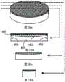
图1是用于超声成像和/或光学成像的成像系统的示意图; Figure 1 is a schematic diagram of an imaging system for ultrasound imaging and/or optical imaging;
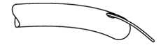
图2是具有连接器、导管以及成像组件的柔性成像探头的透视图; Figure 2 is a perspective view of a flexible imaging probe with a connector, catheter, and imaging assembly;
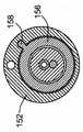
图2a是图2中成像探头的中部沿虚线截取的横截面视图; Figure 2a is a cross-sectional view taken along the dotted line in the middle of the imaging probe in Figure 2;
图2b是图2中成像探头的远端区域的放大透视图; Figure 2b is an enlarged perspective view of the distal region of the imaging probe in Figure 2;
图2c示出了成像探头的旋转部件和非旋转部件如何能够通过适配器连接到成像系统其余部分的示意图; Figure 2c shows a schematic diagram of how the rotating and non-rotating parts of the imaging probe can be connected to the rest of the imaging system via adapters;
图2d是探头的旋转部件和非旋转部件连接到适配器的示例的透视图; Figure 2d is a perspective view of an example where the rotating and non-rotating parts of the probe are connected to the adapter;
图3a至3e是现有技术中描述的一般成像导管配置的代表; Figures 3a to 3e are representative of general imaging catheter configurations described in the prior art;
图3a示出了用于外套的线上配置的一个实施例,该外套在具有引导线内腔时与成像探头相结合; Figure 3a shows an embodiment of an over-the-wire configuration for an overcoat that is combined with an imaging probe when having a guidewire lumen;
图3b示出了沿图3a中的竖线3b-3b穿过成像探头的截面图,用于图示引导线内腔配置; Figure 3b shows a cross-sectional view through the imaging probe along the
图3c示出了用于外套的快速访问配置,该外套在具有引导线内腔时与成像探头相结合; Figure 3c shows a quick access configuration for an overcoat that is combined with an imaging probe when it has a guidewire lumen;
图3d示出了沿图3c中的竖线3d-3d穿过成像探头中不包含引 导线内腔的部分的截面图; Figure 3d shows a cross-sectional view along the vertical line 3d-3d in Figure 3c through the portion of the imaging probe that does not include a guidewire lumen;
图3e示出了沿图3c中的竖线3e-3e穿过成像探头中包含引导线内腔的部分的截面图; Figure 3e shows a cross-sectional view along the vertical line 3e-3e in Figure 3c through the portion of the imaging probe that includes the guidewire lumen;
图4a是包含可倾斜部件的成像探头的远端部分的装配外套的局部切除透视图; Figure 4a is a partial cutaway perspective view of an assembled housing of the distal portion of an imaging probe comprising a tiltable component;
图4b示出了用于包含图4a的可倾斜部件的成像组件的相关轴线; Figure 4b shows the relevant axes for the imaging assembly comprising the tiltable components of Figure 4a;
图4c-4l示出了可倾斜部件的纵向及轴向截面的多个示例,所述可倾斜部件如果在没有外力的情况下绕着成像探头的纵向轴线旋转的话可具有优选的定向,其中倾斜轴线基本上垂直于纵向轴线; Figures 4c-4l show several examples of longitudinal and axial cross-sections of tiltable members that may have preferred orientations if rotated about the longitudinal axis of the imaging probe in the absence of external force, wherein the tilt the axis is substantially perpendicular to the longitudinal axis;
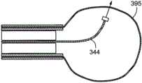
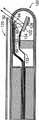
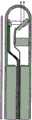
图5a-5g示出了能够进行声学及光学成像的成像探头的远端,其中可倾斜反射表面能够作为成像组件旋转速度的函数而改变成像角度; Figures 5a-5g show the distal end of an imaging probe capable of acoustic and optical imaging, wherein the tiltable reflective surface is capable of changing the imaging angle as a function of the rotational speed of the imaging assembly;
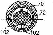
图5h和5i示出了能够用来实施图5e至5g中描述的实施例的成像组件的收折及分解透视图; Figures 5h and 5i show collapsed and exploded perspective views of an imaging assembly that can be used to implement the embodiments described in Figures 5e to 5g;
图6a-6e示出了能够进行声学成像的成像探头的远端,其中声学传感器被直接地安装在可倾斜部件上; Figures 6a-6e show the distal end of an imaging probe capable of acoustic imaging, where the acoustic sensor is mounted directly on the tiltable member;
图6f至6j示出了能够进行光学成像的成像探头的远端,其中光学发射器和/或接收器的至少一部分被直接地安装在可倾斜部件上; Figures 6f to 6j show the distal end of an imaging probe capable of optical imaging, wherein at least a portion of the optical transmitter and/or receiver is mounted directly on the tiltable member;
图7a至7c示出了能够进行声学成像的成像探头的远端的示例,其中可变形部件载有成像和/或治疗能量的发射器和/或接收器。成像角度作为成像组件旋转速度的函数进行改变; Figures 7a to 7c show examples of the distal end of an imaging probe capable of acoustic imaging, wherein the deformable member carries transmitters and/or receivers of imaging and/or treatment energy. The imaging angle changes as a function of the rotational speed of the imaging assembly;
8a和8b示出了成像探头的示例,其中可变形部件被弹性支撑结构所加强,并且成像组件和外套具有可选的冲洗端口; 8a and 8b show an example of an imaging probe where the deformable member is reinforced by an elastic support structure, and the imaging assembly and housing have optional irrigation ports;
图8c和8d示出了成像探头的示例,其中可变形部件被可膨胀气球所环绕,该气球提供了受保护区域,当气球膨胀时探头能够在该受保护区域中移动; Figures 8c and 8d show examples of imaging probes in which the deformable member is surrounded by an inflatable balloon that provides a protected area in which the probe can move when the balloon is inflated;
图9a和9b示出了用于放大所得到的成像角度的GRIN透镜或折射介质的使用; Figures 9a and 9b illustrate the use of GRIN lenses or refractive media to magnify the resulting imaging angles;
图10a和10b示出了成像探头的示例,其中可变形部件载有能量偏转部件而不是发射器和/或接收器; Figures 10a and 10b show examples of imaging probes in which deformable components carry energy deflecting components instead of transmitters and/or receivers;
图11a-11d是可倾斜部件的示例,其中通过在可倾斜部件上加入一个或多个结构特征来用作成像组件流体介质内的翼部,倾斜动作得到了调节并且优选地得以增强; Figures 11a-11d are examples of tiltable members in which the tilting action is modulated and preferably enhanced by incorporating one or more structural features on the tiltable member to act as wings within the fluid medium of the imaging assembly;
图12是可变形部件的示例,其中通过在可倾斜部件上加入一个或多个结构特征来用作成像组件流体介质内的翼部,变形得到了调节并且优选地得以增大; Figure 12 is an example of a deformable member wherein deformation is accommodated and preferably increased by incorporating one or more structural features on the tiltable member to act as wings within the fluid medium of the imaging assembly;
图13a和13b是能够通过本发明实现的一些前方观察扫描图案的示例; Figures 13a and 13b are examples of some forward looking scan patterns that can be achieved by the present invention;
图13c和13d是能够通过本发明成像的侧向观察空间的示例; Figures 13c and 13d are examples of side viewing spaces that can be imaged by the present invention;
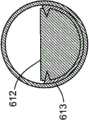
图14a是成像探头的示例,该探头包括用作偏转件的可倾斜部件,以及光学旋转编码器,该编码器用于确定成像组件相对于外套的角度位置; Figure 14a is an example of an imaging probe comprising a tiltable member acting as a deflector, and an optical rotary encoder for determining the angular position of the imaging assembly relative to the housing;
图14b提供了包括旋转编码器的探头的横截面视图; Figure 14b provides a cross-sectional view of a probe including a rotary encoder;
图15是成像探头的示例,其中可倾斜部件的倾斜在一部分上通过以机械方式连接到另外的可倾斜部件而实现; Figure 15 is an example of an imaging probe in which the tilting of the tiltable component is achieved in part by being mechanically connected to another tiltable component;
图16a至16c是成像探头的示例,其中超声传感器或光学成像发射器被配置成主要用于侧向观察成像,其中扫描机构允许成像角度的改变; Figures 16a to 16c are examples of imaging probes in which ultrasonic transducers or optical imaging transmitters are configured primarily for side-view imaging, where the scanning mechanism allows for changes in imaging angle;
图17a-g示出了适于将光学成像与用于本发明的超声传感器相结合的实施例; Figure 17a-g shows the embodiment that is suitable for combining optical imaging with the ultrasonic transducer that is used in the present invention;
图18a是偏转部件的透视图,该偏转部件包括平坦的光学反射层以及成形的声学反射层; Figure 18a is a perspective view of a deflection component comprising a flat optically reflective layer and a shaped acoustically reflective layer;
图18b至18d示出了偏转部件的横截面; Figures 18b to 18d show cross-sections of deflection components;
图19a和19b示出了使用具有可转向引导线从而使前方观察导管的远端区域发生偏转的柔性成像探头或者成像导管的示例; Figures 19a and 19b show an example of using a flexible imaging probe or imaging catheter with a steerable guide wire to deflect the distal region of the forward viewing catheter;
图19c和19d示出了成像探头的示例,其中可转向引导导管被用来使成像探头的远端区域偏转; Figures 19c and 19d show examples of imaging probes in which a steerable guide catheter is used to deflect the distal region of the imaging probe;
图19e至19h示出了与可转向引导线共同使用的成像探头的示例,该可转向引导线的远端区域上方结合有可膨胀气球,从而能够形成足够大的通路用于成像探头行进穿过堵塞区;以及 Figures 19e to 19h show an example of an imaging probe used with a steerable guidewire incorporating an inflatable balloon over the distal region to enable the creation of a pathway large enough for the imaging probe to travel through congested areas; and
图20a和20b示出了加重的弹性件如何能够被连接到可倾斜部件从而帮助引起可倾斜部件的偏转。 Figures 20a and 20b show how a weighted elastic can be connected to the tiltable member to help cause deflection of the tiltable member. the
具体实施方式Detailed ways
一般而言,这里所描述的系统指的是使用光学或者超声(或全部两者)成像的成像探头。根据需要,在此公开本发明的实施例。然而,所公开的实施例仅仅是示例性的,并且应当理解的是本发明可以以多种多样的以及替代的形式进行实施。附图并非按比例绘制,并且一些特征被进行了放大或缩小,以显示特定元件的细节,而相关元件则可能被省去了,以防止遮挡新颖的部分。因此,这里所公开的特定结构和功能细节并不被理解为限制性的,而是仅仅作为权利要求的基础以及作为教示本领域技术人员以各种方式实施本发明的代表性基础。出于教示以及并非限制性的目的,所示实施例涉及成像探头。 In general, systems described herein refer to imaging probes that use optical or ultrasound (or both) imaging. Embodiments of the present invention are disclosed herein as necessary. However, the disclosed embodiments are exemplary only, and it should be understood that the invention may be embodied in various and alternative forms. The figures are not to scale and some features have been exaggerated or minimized to show details of particular elements while related elements may have been omitted so as not to obscure novelty. Therefore, specific structural and functional details disclosed herein are not to be interpreted as limiting, but merely as a basis for the claims and as a representative basis for teaching one skilled in the art to variously employ the present invention. The illustrated embodiments relate to imaging probes for purposes of instruction and not limitation. the
如在此使用的,当与尺寸、温度或者其它物理属性或特征的范围共同使用时,术语“大约”、“近似”指的是涵盖了存在于尺寸范围的上限及下限中的微小变化,从而不排除那些平均起来大部分尺寸都满足但是在统计学上的尺寸可能处于该区域之外的实施例。例如,在本发明的实施例中,给出了成像探头的部件尺寸,但是应当理解的是,这些都不意味着进行限制。 As used herein, the terms "about" and "approximately" when used in conjunction with ranges of size, temperature, or other physical properties or characteristics, are meant to encompass minor variations that exist in the upper and lower limits of the size range such that Embodiments where on average most of the dimensions are met but statistically may be outside this region are not excluded. For example, in the embodiments of the present invention, the dimensions of the components of the imaging probe are given, but it should be understood that these are not meant to be limiting. the
如在此使用的,词组“图像的联合配准”指的是识别由一种成像装置获取的成像数据的子集与利用另一种成像装置获取的成像数据的子集的过程,其中所识别的来自所述两种装置的成像数据是通过检测来自同一物体(或者在本发明情况下为组织)的成像能量的形式(例如光子或超声)而获取的。第一子集中的每个联合配准点然后能够映射到第二子集中的对应点,使得来自所述两种不同成像装置的两个点被认为是从被成像物体(或组织)的相似病灶区域获取的。 As used herein, the phrase "co-registration of images" refers to the process of identifying a subset of imaging data acquired by one imaging modality with a subset of imaging data acquired with another imaging modality, where the identified The imaging data from both devices is acquired by detecting a form of imaging energy (eg photons or ultrasound) from the same object (or tissue in the present case). Each co-registration point in the first subset can then be mapped to a corresponding point in the second subset, such that two points from the two different imaging modalities are considered to be similar focal regions from the imaged object (or tissue). acquired. the
在使用两个或更多个成像装置所获取的图像之间,图像或者图像一部分的成功且精确的联合配准是有用的,因为它能够提供多个机会来通过多于一个成像装置来评定被成像物体的关注特征。 Successful and accurate co-registration of images, or portions of images, between images acquired using two or more imaging modalities is useful because it can provide multiple opportunities to assess Features of interest in imaged objects. the
图1表示了根据本发明构造的示例性成像系统的概视图,该系统总体表示为10。该系统包括成像探头12,该探头12经由适配器14连接到图像处理及显示系统16。图像处理及显示系统16包括必要的硬件来支持下述成像形式中的一种或多种:1)超声,2)光学相干断层成像,3)血管镜法,4)红外成像,5)近红外成像,6)Raman光谱成像,以及7)荧光成像。 Figure 1 shows a general view of an exemplary imaging system, generally indicated at 10, constructed in accordance with the present invention. The system includes an
光学相干断层成像、超声、血管镜法以及红外成像回路的实施已在现有技术中进行了描述。 Implementations of optical coherence tomography, ultrasound, angioscopy, and infrared imaging circuits have been described in the prior art. the
这里描述的系统通常进一步包括控制器和处理单元18,以便于系统的多个功能性单元的协同行为,并且可进一步包括显示器和/或用户界面,并且可进一步包括电极传感器以获取来自被成像病人的身体的心电图信号。所述心电图信号可被用来在心脏运动对图像质量可能产生影响的情况下设定成像数据获取的时间。心电图还可用作触发器,用于何时开始获取序列,例如何时开始改变电机的旋转速度以使期望的扫描图案开始生效。例如,成像序列的ECG触发启动可使得能够在心脏循环的特定阶段(例如心脏收缩或心脏舒张)期间获取图像。 The systems described herein generally further include a controller and processing unit 18 to facilitate the coordinated action of the multiple functional units of the system, and may further include a display and/or user interface, and may further include electrode sensors to obtain data from the patient being imaged. EKG signal of the body. The electrocardiogram signal may be used to time imaging data acquisition in situations where cardiac motion may have an impact on image quality. The ECG can also be used as a trigger for when to start an acquisition sequence, such as when to start changing the rotational speed of a motor so that a desired scan pattern begins to take effect. For example, ECG-triggered initiation of an imaging sequence may enable acquisition of images during specific phases of the cardiac cycle, such as systole or diastole. the
如果包含在本发明的特定实施例中的话,形成图像处理及显示系统的光学回路及电子元件21可包括下述部件中的任何一个或全部:干涉计部件、一个或多个光学参考臂、光学多路复用器、光学多路分配器、光源、光检测器、分光计、压电滤光器、计时电路、模数转换器以及对于实现在背景技术和现有技术部分中描述的任意光学成像技术所公知的其它部件。超声回路20可包括以下部件中的任何一个或全部:脉冲发生器、电子滤波器、模数转换器、平行处理阵列、包络检波、包括时间增益补偿放大器的放大器以及对于实现在背景技术和现有技术部分中描述的任意声学成像技术所公知的其它部件。 The optical circuitry and electronics 21 forming the image processing and display system may include any or all of the following components, if included in a particular embodiment of the invention: interferometer components, one or more optical reference arms, optical Multiplexers, optical demultiplexers, light sources, photodetectors, spectrometers, piezoelectric filters, timing circuits, analog-to-digital converters, and any optical other components known to the imaging art.
如果包含在本发明的特定实施例中的话,控制器和处理单元18用于多种目的,并且部件将根据特定成像系统的需要而显著地进行适应。控制器和处理单元18可包括电机驱动控制器、数据存储部件(例如内 存、硬盘、可移动存储装置、用于便携式存储介质例如CD和DVD的读取器和记录器)、位置检测电路、计时电路、心脏选通功能、测定体积图像处理器、扫描转换器及其它装置中的一种或其组合。可选地,还可设置显示器和用户界面22,用于实时显示或者成像数据获取时刻后某一时刻的数据显示。 The controller and processing unit 18, if included in a particular embodiment of the invention, serve multiple purposes, and the components will be tailored significantly according to the needs of a particular imaging system. Controller and processing unit 18 may include motor drive controllers, data storage components such as memory, hard disks, removable storage devices, readers and recorders for portable storage media such as CDs and DVDs, position detection circuitry, One or a combination of timing circuits, cardiac gating functions, volumetric image processors, scan converters and other devices. Optionally, a display and user interface 22 may also be provided for real-time display or data display at a certain time after the imaging data acquisition time. the
成像探头12包括其远端32附近的成像组件30、沿着其长度大部分的可选成像导管34以及其近端38的连接器36。对于本发明,成像组件30一般指的是从中收集信号(声学或光学或者两者)的成像探头12的部件,用于靠近成像组件30的区域的成像。成像组件30包括一个或多个成像能量发射器以及一个或多个成像能量接收器。对于本发明,“成像能量”指的是光能或声能或者两者。具体地,光指的是覆盖紫外线、可见光以及红外光谱波长的电磁波。例如,对于声学成像,成像组件30包括超声传感器,该超声传感器既是声能的发射器又是声能的接收器。
对于光学成像,光学组件30一般包括光纤的远端,以及光学部件例如透镜(例如球透镜或GRIN透镜)的组合,所述部件共同地用作光学接收器并可用作光学发射器。镜和/或棱镜通常结合作为光学发射器和/或接收器的一部分。成像组件30、连接器36和/或成像导管34可以是充有液体的(例如盐水),并且可冲洗。 For optical imaging,
成像探头12可以在沿着其长度的一个或多个点上包含端口,以便于冲洗。对于光学成像,可以考虑充有气体的成像探头12。优选地,所述气体基本上包括二氧化碳或者其它容易溶解的气体。可替代地,成像组件可被分区,从而存在至少一个充有气体的分区或内腔用于光学成像以及至少一个充有液体的分区或空腔用于声学成像。
成像导管34包括至少一个光学波导管或者至少一根导线(优选为两根或多根),所述导线将发射器和/或接收器经由连接器连接到适配器。成像导管34还可用作机械力传递机构,用于旋转或者平移成像组件。例如,成像导管34可包括被两层彼此绝缘的电线缠绕的光纤。成像导管34可进一步通过其它结构特征得到加强,例如螺旋缠绕线或者其它用于构成成像力矩线缆的设计,所述线缆用于使扫描机构旋转,如相关技术中所述。 The
适配器14便于将任何光纤和/或线中的信号传送到适当的图像处理单元。适配器优选包括电机驱动单元,用于向成像探头的旋转部件施加旋转运动。适配器14还可结合有回拉机构49(图2d)或者往复推拉机构,以便于成像组件的纵向平移。成像组件30的这种纵向平移可以与环绕成像导管34的外轴的纵向平移共同发生,或者在相对静止的外轴内发生。
可结合附加的传感器作为适配器14的一部分,例如位置感测回路,用于感测成像探头12内的旋转部件的旋转角度。成像探头12还可包括存储部件,例如EEPROM或其它可编程存储装置,其包括关于成像探头到成像系统其余部分的信息。例如,它可包括关于成像探头12的规格识别的说明,并还可包括关于探头12的校准信息。此外,适配器14可包括放大器,用于提高成像探头与系统其余部分之间的电信号或动力的传送。 Additional sensors may be incorporated as part of
重要的是认识到需要最优化最低侵入性探头的几何形状,从而使其能够尽可能合理地小,从而达到其期望目的。当前的IVUS和ICE探头的直径大约为0.9至4mm并且探头的较小尺寸能够在冠状解剖体的血管树中随着血管尺寸逐渐变细而被递送得更远。因此,较小的尺寸通常允许了对大部分冠状解剖体的访问。由此希望使探头实施例能够在使探头的某些尺寸(例如探头直径)最小化的配置中进行成像,例如利用在此描述的扫描机构进行成像。 It is important to recognize the need to optimize the minimally invasive probe geometry so that it can be as small as reasonably possible for its intended purpose. Current IVUS and ICE probes are approximately 0.9 to 4 mm in diameter and the smaller size of the probes enables delivery farther in the vascular tree of the coronary anatomy as vessel sizes taper. Thus, the smaller size generally allows access to most of the coronal anatomy. It is thus desirable to enable probe embodiments that enable imaging, such as with the scanning mechanisms described herein, in configurations that minimize certain dimensions of the probe (eg, probe diameter). the
图2是包含光纤40和同轴电线50的柔性导管的透视图。近端连接器包含光纤40,该光纤40能够被适配器接收从而将成像光纤40以光学方式连接到光学成像系统“后端”。还具有电连接器56,其允许一个或多个电导管连接到超声回路和/或控制器和处理单元。在成像导管绕其纵向轴线旋转的实施例中,可能需要将成像光纤的旋转部件与相对静止的光纤相连,该相对静止的光纤连接到光学成像系统的后端16。旋转光纤探头的连接能够通过光纤旋转接头而实现,所述光纤旋转接头结合作为成像探头36的近端连接器的一部分或者作为适配器14的一部分。类似地,在成像导管绕其纵向轴线旋转的实施例中,可能需要将随成像导管旋转的导线连接到超声回路和/或控制器和处理单元的相对静止的导体,优选通过集电环(slip ring)来连接。这些集电环能够被结合作为成像探头36的近端连接器的一部分或者作为适 配器14的一部分。 FIG. 2 is a perspective view of a flexible conduit containing
图2a示出了沿虚线截取的图2中的成像探头的中部的横截面视图,其显示了光纤40、引导线端口44和引导线42、成像导管34、成像导管腔46、中空的外套48、柔性细长轴(由生理上可相容的材料制成并且直径适于允许中空细长轴插入到人体内腔及空腔中)、以及同轴电线50。图2b中所示的成像探头10的端部的放大详图显示出引导线42的远端延伸越过外套48的端部和外套48端部的冲洗端口54。在图2中,成像探头10的近端包括连接器组件36和另一个引导线端口55,引导线42插入到引导线端口55中,连接器组件36包括冲洗端口58和沿着连接器主体的电接触器56。 Figure 2a shows a cross-sectional view of the middle of the imaging probe in Figure 2 taken along the dashed line showing the
图2c显示了成像探头的旋转和非旋转部件如何能够通过适配器连接到成像系统其余部分的示意图。图2d示意性地显示了成像探头的旋转部件如何能够连接到适配器的旋转部件。各个旋转部件可以通过本领域公知的连接器和其它配置以电学、光学、和/或机械的方式进行连接。类似地,成像探头的非旋转部件可以连接到适配器14的非旋转部件。适配器14可包括集电环、光学旋转接头以及其它能够将旋转部件通过电学或光学方式连接到非旋转部件并能够实现与系统其余部分进行必要的电信号及光信号通讯的工具。 Figure 2c shows a schematic of how the rotating and non-rotating parts of the imaging probe can be connected to the rest of the imaging system via adapters. Figure 2d schematically shows how the rotating part of the imaging probe can be connected to the rotating part of the adapter. The various rotating components may be electrically, optically, and/or mechanically connected by connectors and other arrangements known in the art. Similarly, the non-rotating part of the imaging probe can be connected to the non-rotating part of the
也可使用双光纤光学旋转接头,但是该接头要复杂得多。固定到成像探头12中的旋转部件上的任何导体之间的电连接可以经由金属集电环和弹簧、金属集电环和电刷或者其它在静止导体和旋转导体之间形成导电接触的一般公知方法而连接到非旋转导电元件。 A dual fiber optic rotary union can also be used, but this joint is much more complicated. Electrical connections between any conductors secured to the rotating components in
尽管图2d中分开地显示了电连接、光学连接和机械连接,但是根据特定实施例的需要,能够利用通过将多个连接器组合成组合连接器而得到较少的连接器来减少必须单独连接在探头和适配器之间的多个连接器。 Although electrical, optical, and mechanical connections are shown separately in FIG. 2d, depending on the needs of a particular embodiment, fewer connectors obtained by combining multiple connectors into composite connectors can be utilized to reduce the need for separate connections. Multiple connectors between probe and adapter. the
尽管上述实施例通过声学和光学成像两者进行了示例,但是能够实施没有声学装置或者没有光学装置的导管。 Although the above-described embodiments are exemplified with both acoustic and optical imaging, catheters can be implemented without acoustic means or without optical means. the
图3a示出了用于外套48的线上配置的一个实施例,并且图3b示出了外套48沿图3a中的竖线3b-3b穿过包含成像组件30的部分的横截面。在图3a中,从沿着图3a中的竖线3b-3b的图3b的横截面看, 引导线导管44位于外套48的较厚部分中。 Figure 3a shows one embodiment of an in-line configuration for
图3c示出了另一个外套60的实施例,该外套60是用于外套的“快换”配置,如果需要引导线的话,所述外套可以与成像探头相结合。图3c中的套60包括图2中所示的进入端口55。图3d示出了“快换”配置60沿图3c中的线3d-3d穿过靠近用于引导线的进入端口55的部分的横截面。图3e示出了沿图3c中的线3e-3e的横截面。 Figure 3c shows another embodiment of a sheath 60, which is a "quick change" configuration for a sheath that can be combined with an imaging probe if a guide wire is required. The sheath 60 in FIG. 3c includes the
本发明公开了用于提供前方及侧向观察超声(IVUS)及光学相干断层(OCT)成像的扫描机构的实施例。对于超声和光学相干断层成像,当与成像组件的旋转运动相结合时,调节发射出的和/或接收到的成像能量的传播角度的能力允许了对3D空间进行扫描。对于血管镜法和红外成像,当与成像组件的旋转运动相结合时,调节发射出的和/或接收到的成像能量的传播角度的能力允许使用单个光纤而不是需要一束光纤或者一排感光元件来产生图像。这种改进得到了较大的灵活性和/或允许成像装置的进一步小型化。 Embodiments of scanning mechanisms for providing anterior and lateral viewing ultrasound (IVUS) and optical coherence tomography (OCT) imaging are disclosed. For ultrasound and optical coherence tomography, the ability to adjust the angle of propagation of emitted and/or received imaging energy, when combined with rotational motion of the imaging assembly, allows scanning of 3D space. For angioscopy and infrared imaging, the ability to adjust the angle of propagation of emitted and/or received imaging energy, when combined with rotational motion of the imaging assembly, allows the use of a single optical fiber rather than requiring a bundle of optical fibers or an array of photoreceptors components to generate images. Such improvements allow greater flexibility and/or allow further miniaturization of imaging devices. the
本发明的另一个优点是光学和声学成像可以在光学与声学成像能量行进穿过同一总体空间的配置下进行,从而便于光学和声学图像的联合配准,并使成像组件内容纳多于一种成像形式所需的容积大小减到最小。尽管如此,所述扫描机构可以与单一成像形式(例如超声或者单一光学成像技术)相结合来应用。类似地,两种或更多种光学成像技术(与超声相结合或者没有与超声相结合)可以同时使用单个探头上的扫描机构。 Another advantage of the present invention is that optical and acoustic imaging can be performed in a configuration in which optical and acoustic imaging energy travels through the same overall space, thereby facilitating co-registration of optical and acoustic images and allowing the imaging assembly to accommodate more than one The volume size required for the imaging modality is minimized. Nevertheless, the scanning mechanism may be used in conjunction with a single imaging modality such as ultrasound or a single optical imaging technique. Similarly, two or more optical imaging techniques (with or without ultrasound) can be used simultaneously using the scanning mechanism on a single probe. the
图4a示出了成像探头12的远端区域的局部切除透视图,其显示出外套601的一部分605被去除。成像探头12内部设有可倾斜部件602,可倾斜部件602形成成像组件的一部分并且安装在销603上,该销603延伸穿过可倾斜部件602的倾斜轴线604。 Figure 4a shows a partially cut away perspective view of the distal region of the
在能够对用于成像目的的空间进行扫描的本发明多个实施例中,有利地使用了向心加速度原理。现有技术中已经提出了直接使传感器倾斜或者反射器倾斜的机构,例如马达或者线缆和带轮系统。在此公开的本发明多个实施例具有通过改变成像组件的旋转速度来使部件倾斜或变形的能力。 In various embodiments of the invention that enable scanning of space for imaging purposes, the principle of centripetal acceleration is advantageously used. Mechanisms to directly tilt the sensor or the reflector have been proposed in the prior art, such as motors or cable and pulley systems. Various embodiments of the invention disclosed herein have the ability to tilt or deform components by varying the rotational speed of the imaging assembly. the
参考图4b,部件的倾斜或变形用于改变倾斜角度α。成像角度 定义为成像探头12的纵向轴线606与成像能量发射和/或接收方向之间的角度。在本发明中,成像角度是可倾斜部件602的倾斜角度α的函数,或者是可变形部件的变形度的函数,该变形度通常也用倾斜角度α表示。 Referring to Figure 4b, the tilting or deformation of the part is used to change the tilting angle a. The imaging angle is defined as the angle between the
图4b显示了相对于可倾斜部件602的旋转轴线的倾斜角度α的示意性图示,其中可倾斜部件602被显示为绕倾斜轴线604枢转的盘体。改变成像系统的可倾斜或可变形部件602的角速度以及随后改变成像角度的能力将会在下面对发明的描述中以及通过实验结果来进行说明。 FIG. 4 b shows a schematic illustration of the angle of inclination a relative to the axis of rotation of the
首先,对通过可倾斜部件602来改变成像角度的情况进行描述。成像组件包括能够绕轴线604(倾斜轴线)旋转的可倾斜部件602,该轴线604基本上垂直于成像探头的纵向轴线606。例如,可倾斜部件602可以安装到铰链上或者以其它方式与铰链相关联,安装到一个或多个销(例如前面提到的销603)上或者以其它方式与销相关联、安装到弹簧或可变形基板上或者以其它方式与之相关联,从而能够绕倾斜轴线604旋转。 First, the case where the imaging angle is changed by the
可倾斜部件602特别地具有以下特性:当成像组件绕除倾斜轴线之外的轴线旋转时,可倾斜部件602具有不连续的多个优选定向(通常为一个或两个)。优选地,成像组件的旋转轴线基本上与成像探头的纵向轴线606相重合(即,基本上平行或者接近)。优选地,倾斜轴线与纵向轴线正交。在除了成像组件旋转中所涉及的向心力之外没有重力或者任何其它力(例如下面提到的回复力)的情况下,可倾斜部件602将会绕着倾斜轴线将其自身定向到优选的方位。 The
图4c到4l显示了可倾斜部件的纵向及轴向截面的多个非限制示例,所述可倾斜部件如果在没有外力的情况下绕着成像探头12的纵向轴线606旋转,则会具有优选的定向,其中倾斜轴线604基本上垂直于纵向轴线606。 4c to 4l show several non-limiting examples of longitudinal and axial cross-sections of tiltable members that, if rotated about the
具体地,图4c是成像探头的实施例的示例的纵截面视图,其中可倾斜部件是安装在销611上的盘体610。图4d是沿着线4d-4d截取的对应横截面视图。 In particular, FIG. 4c is a longitudinal section view of an example of an embodiment of an imaging probe in which the tiltable member is a
图4e是成像探头的实施例的纵截面视图,其中可倾斜部件是安 装在支架613上的球体612的一部分。图4f是沿着图4e的线4f-4f截取的对应的横截面视图。 4e is a longitudinal sectional view of an embodiment of an imaging probe in which the tiltable member is part of a
图4g是成像探头的实施例的纵截面视图,其中可倾斜部件614具有更加任意的形状,并且利用隔离件615(仅在图4h中可见)安装在销611上,该隔离件615有助于稳定可倾斜部件614在销611上的位置。图4h是沿着图4g的线4h-4h截取的对应横截面视图。 Figure 4g is a longitudinal sectional view of an embodiment of an imaging probe in which the
图4i是成像探头的实施例的纵截面视图,其中可倾斜部件620通过销622来安装,从而使得可倾斜部件620绕着枢转轴线626枢转。图4j是沿着图4i的线4j-4j截取的对应横截面视图,该图4j显示了销622延伸到榫头(divot)624中,该榫头624位于可倾斜部件620的侧部并且接收销622。该实施例中的枢转机构的较小表面面积有利于将绕着枢转轴线626的摩擦降到最小。优选地,销622仅在销尖端附近与可倾斜部件620接触,从而使表面接触面积减至最小。 4i is a longitudinal sectional view of an embodiment of an imaging probe in which the
图4k是成像探头的实施例的纵截面视图,其中可倾斜部件630利用枢转轴线632来安装,该枢转轴线632不与成像探头的旋转轴线606相交。图4l是沿着图4k的4l-4l截取的对应横截面视图。从功能上看,在包含可倾斜部件的实施例中,枢转轴线与倾斜轴线完全相同。 Figure 4k is a longitudinal cross-sectional view of an embodiment of an imaging probe in which the
可倾斜部件70的功能性目的是能够改变与成像探头31的的纵向轴线的角度(图5a),成像能量(例如光束或声能)以该角度向周围环境发射和/或从周围环境接收。这能够通过将发射器和/或接收器(例如超声传感器或光学部件)安装在可倾斜部件70上而实现。通过改变成像组件的旋转速度,倾斜角度将发生改变并且由此发射和/或接收光能或声能的角度将发生改变。 The functional purpose of the
可替代地,可倾斜部件可被用于使发射出的和/或被部件88接收的成像能量发生偏转,该部件88未直接连接到可倾斜部件70,如图5所示。例如,如上所述,超声传感器88或者光学发射器92能够将成像能量导向可倾斜部件70。成像能量随后被安装在可倾斜部件70上的能量偏转部件所偏转。对于超声成像,能量偏转部件(可倾斜部件70)可包括声学反射表面,例如实心金属表面(例如不锈 钢)或者水晶表面,例如石英晶体或玻璃或硬质聚合体。 Alternatively, a tiltable member may be used to deflect imaging energy emitted and/or received by a
对于光学成像,能量偏转部件(可倾斜部件70)可包括光学反射表面,例如由抛光金属、金属化聚合体(例如金属化双轴定向聚对苯二甲酸乙二醇酯(Mylar))、溅射或电化学沉积金属所制成的镜面,金属箔片或者其它反射部件(例如薄膜反射器)。通常用来制造镜面的金属包括铝、银、钢、金或铬。 For optical imaging, the energy deflecting member (tiltable member 70) may include optically reflective surfaces, such as those made of polished metal, metallized polymers (such as metallized biaxially oriented polyethylene terephthalate (Mylar)), sputtered Mirrors, metal foils or other reflective components (such as thin film reflectors) made of metals made by radiation or electrochemical deposition. Metals commonly used to make mirrors include aluminum, silver, steel, gold or chrome. the
图5a示出了成像探头31的远端29的实施例,成像探头31含有包括可倾斜部件70的成像组件30,其中可倾斜部件是安装在销72上的盘体,该销72使得盘体70能够绕销枢转,与上面讨论的图4b类似。销72限定了可倾斜盘体70的倾斜轴线。当成像组件30静止的时候,盘体70将保持在任意开始位置。在所示示例中,该开始位置由挡块80限定,该挡块80对应于最大成像角度,其中由扭转弹簧76提供的回复力朝前述挡块80推动盘体70。图5b示出了沿着图5a的线5b-5b的横截面。 Figure 5a shows an embodiment of the
如果可倾斜部件70在外力(例如重力、磁力、静电学、与其他移动部件或流体的摩擦力、压缩力、悬臂力、法向力或者可倾斜部件70上绕着倾斜轴线的不完全相对的力矩的任意其它来源)作用下倾斜离开其优选定向,那么倾斜角度将增大。 If the
一个或多个挡块80和82可限制可倾斜部件70的倾斜角度范围。例如,挡块80可以是从成像组件30的套84延伸的柱或者缘,作为当倾斜部件70与挡块80接触时防止倾斜部件70进一步改变其倾斜角度的挡块。由此,挡块可被用来限制倾斜角度超过由挡块的位置确定的最大值。一旦倾斜角度达到最大值,由挡块80施加到可倾斜部件70上的法向力抵抗回复机构。在多个实施例中,该最大倾斜角度是当成像组件30处于静止以及处于低旋转速度时获得的倾斜角度。 One or
附加的或替代性的挡块82可以被包括进来,用于产生最小倾斜角度,当可倾斜部件70处于操作范围上端的旋转速度时,将获得该最小倾斜角度。事实上,很多情况下允许倾斜角度达到零并没有明显的好处,这在接下来对具体实施例的描述中将变得清楚。 An additional or
优选地,成像组件30包括一个或多个趋向于使可倾斜部件70 的倾斜角度增加的机构。对于本发明,这种机构指的是回复机构。扭转弹簧76(如图5a和5c所示)或者压缩弹簧可被用作回复机构,其中扭转弹簧76的一端以机械方式与可倾斜部件70接触或者与其相连。另一端以机械方式连接到成像探头31的另一部分,例如成像组件的主体。 Preferably,
随着成像组件30旋转,盘体70将希望使其自身对齐,使得由盘体70的表面限定的平面的法线基本上平行于所述纵向轴线。如图5c所示,所示的另一个挡块82(与最小成像角度相对应)将阻止盘体70在成像组件的高速旋转速度下到达其优选定向。通过适当配置的成像组件,与最小成像角度相对应的挡块82可以对应零角度,从而提供沿平行于成像探头的纵向轴线的方向的成像。图5d示出了沿着图5c的线5d-5d的横截面。 As the
可替代地,可以应用磁性的、静电的、水力的或者其它能够围绕倾斜轴线施加力矩在可倾斜部件上的机构。能够用来提供回复力的机构的其它示例包括来自弹性体(例如橡胶、聚亚安酯、硅树脂、含氟弹性体、热塑性弹性体以及许多其它材料)的张力或者通过使用悬臂弹簧或薄片(foil)。在成像装置的非常少的实施例中,其中成像组件的部件之间的分子间力(例如静电力)以及范德瓦尔斯力在即使没有施加外部电压的情况下也可能变得十分显著,可倾斜部件与靠近可倾斜部件的结构(例如下面描述的挡块80和82)之间固有的分子间力足以提供净回复力(net restoring force)。例如,包括由PVC或LDPE制成的表面的挡块可以在可倾斜部件和挡块之间提供足够的吸引力。这与使用塑料膜来覆盖家用容器从而用于食品储藏(即,Glad Wrap保鲜膜)的方式相似。 Alternatively, magnetic, electrostatic, hydraulic or other mechanisms capable of exerting a moment on the tiltable member about the tilt axis may be applied. Other examples of mechanisms that can be used to provide the restoring force include tension from elastomers such as rubber, polyurethane, silicone, fluoroelastomers, thermoplastic elastomers, and many others, or through the use of cantilevered springs or thin sheets ( foil). In very few embodiments of imaging devices in which intermolecular forces (e.g., electrostatic forces) as well as van der Waals forces between components of the imaging assembly can become significant even in the absence of applied external voltages, the The inherent intermolecular forces between the tilting member and structures adjacent to the tiltable member, such as
图5e示出了用于成像探头600的扫描机构的实施例,其中图5a的扭转弹簧76由简易的悬臂线640替代,该悬臂线640与可倾斜部件70的表面接触,并且连接到柱787以产生回复力。悬臂640可由镍钛诺、铂、金或包括聚合体的多种其它适当材料制成。 FIG. 5e shows an embodiment of a scanning mechanism for an
图5f示出了用于成像探头670的扫描机构的实施例,其中可倾斜部件70包括磁体680,成像组件的非倾斜部件包括磁体681,该磁体681用来产生回复力。磁体可被定向成使得它们根据它们在成像组件内的相对位置而相互吸引或排斥。磁体681中的一个可以是电磁体, 使得它的强度可以根据需要进行调整或改变,以改变成像角度。该电磁体可以通过从磁体向探头近端伸展的导体(未示出)被提供能量。如果可倾斜部件70具有一定程度的铁磁性,那么可倾斜部件70上可以不具有磁性部件,并且单单一个磁体就足以产生回复力,如图5g所示。 Figure 5f shows an embodiment of a scanning mechanism for an
应当注意的是,在成像组件或成像导管没有任何旋转运动的情况下,电磁体可以被用来偏转可倾斜部件70并且通过改变通过电磁体的电流来产生用于成像的扫描图案。 It should be noted that without any rotational movement of the imaging assembly or imaging catheter, the electromagnet can be used to deflect the
图5h提供了成像组件30实施例的透视图,而图5i提供了同一实施例的分解视图。可倾斜部件70用作超声传感器88产生的成像能量的偏转件。销752凹入到可倾斜部件70的侧面中的孔内并且通过压配或者粘结而固定于此。在该实施例中,销指向外并且被各个销保持件751中的榫头(未示出)所接收。在装配期间,销保持件751被固定在成像组件30的套753内。销751和销保持件752形成枢转轴线,可倾斜部件可以在该枢转轴线上低摩擦地枢转。连接到套753的挡块82限制了可倾斜部件70的最大倾斜角度。悬臂弹簧从套的后部开始延伸并且与可倾斜部件的底表面接触,使得当成像组件绕纵向轴线具有极小旋转或没有旋转时,可倾斜部件停留在其最大成像角度。 Figure 5h provides a perspective view of an embodiment of
参考图5a至5g,成像组件30可包括光学发射器/接收器以及相关的定向和聚焦光学和/或超声传感器。超声传感器88安装在小的同轴线缆89的端部。可选的光学隔离件(未示出)以及透镜92安装在靠近图5a中成像组件30中的镜94的光纤线缆96的端部,其中光学和超声发射器被设置成将成像向可倾斜部件70传送以及接收来自可倾斜部件70的成像能量。可选的光学隔离件可以仅仅是透明介质,例如玻璃或聚合体(例如未包层纤维),其可以被放置在光纤远端与透镜之间,从而提高工作距离或者光学成像系统的容差,如Mao所述。 Referring to Figures 5a to 5g,
优选地,发射器和/或接收器安装在成像组件中与成像组件共同旋转的部件上。然而,还可以将发射器和/或接收器安装在成像探头中的当成像组件内的能量偏转机构旋转时不与成像组件共同旋转的部件上。这可以通过将发射器和/或接收器安装在外套上或者通过将 成像组件分成两个或更多个子组件(其中一个子组件旋转并且包括可倾斜部件70)来实现。 Preferably, the transmitter and/or receiver are mounted on a part of the imaging assembly that co-rotates with the imaging assembly. However, it is also possible to mount the transmitter and/or receiver on parts of the imaging probe that do not co-rotate with the imaging assembly when the energy deflection mechanism within the imaging assembly rotates. This can be accomplished by mounting the transmitter and/or receiver on the housing or by dividing the imaging assembly into two or more subassemblies (one of which rotates and includes the tiltable member 70). the
如图5a至5i所示,使用能量偏转部件来改变成像角度而不是直接发射器和/或接收器安装在可倾斜部件(如图6a至6e所示)是有利的。当传感器直接安装在可倾斜部件的时候,倾斜动作可被发射器和/或接收器的机械特性以及电学和/或光学导管的机械特性所阻止,所述电学和/或光学导管将发射器和/或接收器连接到成像系统的其余部分。发射器和/或接收器可能太占体积而不能方便地放置在可倾斜或可弯曲部件上。 As shown in Figures 5a to 5i, it is advantageous to use energy deflecting components to change the imaging angle rather than direct emitters and/or receivers mounted on tiltable components (as shown in Figures 6a to 6e). When the sensor is mounted directly on the tiltable part, the tilting action can be prevented by the mechanical properties of the transmitter and/or receiver and the mechanical properties of the electrical and/or optical conduits that connect the transmitter and and/or the receiver is connected to the rest of the imaging system. The transmitter and/or receiver may be too bulky to be conveniently placed on the tiltable or bendable member. the
此外,反射表面的使用有效地使成像角度的变化加倍。例如,反射表面的倾斜角度的变化导致了成像角度的变化,该成像角度的变化通常是倾斜角度变化的两倍。成像角度的这种加倍能够增加可由多个实施例中扫描机构获得的视野的大小。 Furthermore, the use of reflective surfaces effectively doubles the variation in imaging angle. For example, a change in the tilt angle of the reflective surface results in a change in imaging angle that is typically twice as large as the change in tilt angle. This doubling of the imaging angle can increase the size of the field of view obtainable by the scanning mechanism in various embodiments. the
在声学成像的情况下,可能的是,强烈的声学脉冲施加到声学反射表面上将会分配一些机械能量到可倾斜部件中。这会发生在声学反射表面不用作理论上完美的反射器的情况下,并且会导致可倾斜部件或可倾斜部件的某些子部件产生振动。这种振动可能会促成任何所得图像中的人为因素,特别是当这种振动的能量被向回导向声学接收器时。由此,必须在可倾斜部件中加入阻尼机构。适于作衬靠声学超声传感器的材料可用于该目的,例如混合有钨粉的环氧树脂。阻尼机构可以是可倾斜部件内的附加层,或者可以结合到其上安装有可倾斜部件的铰链或销的设计中,例如通过在销上、或者在可倾斜机构中接收销的任何孔中添加阻尼材料层。 In the case of acoustic imaging, it is possible that the application of a strong acoustic pulse to the acoustically reflective surface will distribute some mechanical energy into the tiltable member. This can occur where the acoustically reflective surface does not act as a theoretically perfect reflector and can cause vibrations in the tiltable part or some sub-components of the tiltable part. Such vibrations may contribute to artifacts in any resulting images, especially if the energy of such vibrations is directed back toward the acoustic receiver. Therefore, it is necessary to incorporate a damping mechanism in the tiltable part. Materials suitable for lining acoustic ultrasonic sensors can be used for this purpose, such as epoxy mixed with tungsten powder. The damping mechanism may be an additional layer within the tiltable part, or may be incorporated into the design of the hinge or pin on which the tiltable part is mounted, for example by adding it on the pin, or in any hole that receives the pin in the tiltable mechanism Damping material layer. the
图6a到6e示出了成像探头的远端,该成像探头包括能够进行声学成像的成像探头,其中扫描机构包括直接安装在可倾斜部件上的声学传感器。更具体地,图6a示出了包括可倾斜部件302的成像组件300的实施例,该可倾斜部件302以枢转方式安装在销312上,并且声学传感器304安装在该可倾斜部件302上。挡块306限定了能够获得的最大成像角度。一对导电元件308从成像导管34延伸到声学传感器304。导电元件308优选具有非常柔性的构成(例如细的同轴线)或者薄膜构成,该薄膜构成允许薄膜内具有一条或多条导电通路。由于导电元件308的机械特性,导电元件308可以提供 回复机构,由此导电元件308趋向于促使可倾斜部件302达到具有最大倾斜角度的设置。 Figures 6a to 6e show the distal end of an imaging probe comprising an imaging probe capable of acoustic imaging where the scanning mechanism comprises an acoustic sensor mounted directly on the tiltable member. More specifically, FIG. 6a shows an embodiment of an
例如,如图6a所示,导电元件308的刚度提供了足够的力促使可倾斜部件302靠着挡块306,并且由此获得了对于特定实施例的最大成像角度。该角度可以在成像组件300不旋转或者绕着成像探头的纵向轴线以低角速度旋转时获得。图6b中所示的成像组件300显示了当角速度增加时,可倾斜部件302如何将其自身对齐到优选的配置并由此改变成像角度。 For example, as shown in Figure 6a, the stiffness of the
可以注意到,尽管图6a和6b中所示的成像角度和倾斜角度基本上相等,但是声学传感器304可以安装到可倾斜部件302上,以使成像角度和倾斜角度发生偏移。例如,可倾斜部件302的几何构造可包括安装传感器304的斜表面,或者可以在传感器304和可倾斜部件302之间加入薄垫片以使成像角度和倾斜角度发生偏移。还可以注意到,图6a和6b中所示的实施例中还可以包括其它回复机构。声学传感器304还可以凹进到可倾斜部件302内,如图6c所示。 It may be noted that although the imaging and tilting angles are shown in Figures 6a and 6b to be substantially equal, the
对于某些实施例,导体与可倾斜部件上的声学传感器的连接可能会导致导体过于刚性以致于不能允许可倾斜部件以充分的保真度倾斜以用于期望的应用。在这种情况下,可使用导电连接器,如Maroney等人在美国专利5373849中所描述的。可替代地,枢转机构的一个或多个部分(例如用于可倾斜机构的枢转机构的一个或多个销)可以起到与可倾斜部件上电绝缘导体的电接触的第二用途。 For some embodiments, the connection of the conductor to the acoustic sensor on the tiltable member may result in a conductor that is too rigid to allow the tiltable member to tilt with sufficient fidelity for the desired application. In this case, a conductive connector can be used, as described by Maroney et al. in US Patent 5,373,849. Alternatively, one or more parts of the pivot mechanism, such as one or more pins for the pivot mechanism of the tiltable mechanism, may serve a secondary purpose of electrical contact with electrically insulated conductors on the tiltable member. the
图6d和6e示出了销310的使用,该销310电连接到同轴线缆,以提供与可倾斜部件302内的导电通路的电接触,从而提供与可倾斜部件302上的传感器304的连接。除了在销310与可倾斜部件302接触的尖端外,导电通路在销310的芯内是绝缘的。类似地,除了在与销310尖端的接触点外,可倾斜部件用于接收销310的凹口可以是电绝缘的。在这种情况下,可倾斜部件302附近的流体可选地包括导电率低于盐水的流体,例如蒸馏水或矿物油。可替代地,可使用O形环来提高电接触点处的电绝缘。 FIGS. 6d and 6e illustrate the use of a
可替代地,导电元件308可被光纤替换,并且声学传感器304可被一个或多个光学接收器和/或发射器替换。 Alternatively,
图6f至6j示出了能够进行光学成像的成像探头的远端,其中光学发射器和/或接收器的至少一部分直接安装在可倾斜部件上。在图6f和6g中,能量偏转部件由透射性的折射元件392(例如玻璃、纯聚合物以及很多其它材料)制成,并且以类似于棱镜或透镜的方式使成像能量偏转。来自安装在成像组件30内的光纤391的光(light)朝安装在可倾斜部件70上的折射元件392发光。光纤的远端可由光学隔离件或GRIN透镜来终止,如本发明中其它附图所示。在图6f和6g的实施例中,光学发射器和/或接收器仅有一部分直接安装在可倾斜部件上。透射性折射元件392不直接连接到光纤391的远端,从而使得可倾斜部件70更容易倾斜,而不会受到来自光纤391的任何机械影响的妨碍。 Figures 6f to 6j illustrate the distal end of an imaging probe capable of optical imaging, wherein at least a portion of the optical transmitter and/or receiver is mounted directly on the tiltable member. In Figures 6f and 6g, the energy deflecting component is made of a transmissive refractive element 392 (eg, glass, pure polymer, and many other materials) and deflects imaging energy in a manner similar to a prism or lens. Light from an
在图6h至6j中,光学发射器和/或接收器的整个远端(包括光纤391的远端)以机械方式与可倾斜部件70相连。光纤391还可以用作机械部件,用于提供使可倾斜部件70以最大倾斜角度倾斜的回复力,如图6h所示。在更高旋转速度下,可倾斜部件70将趋向于如图6i所示地对齐。图6提供了成像组件30的前视图。 In FIGS. 6h to 6j , the entire distal end of the optical transmitter and/or receiver, including the distal end of the
可替代地,图6a至6j中的导电元件308和光纤391可以被导电元件308和一个或多个光纤391的组合替代,同时声学传感器302被导电元件308和一个或多个光纤391的组合替代。应当注意到,在某些实施例中增加导电元件308和/或光纤的数目会对可倾斜部件能够获得的成像角度的范围产生影响,这是导电元件308和/或光纤的刚度增强的结果。 Alternatively, the
对于某些实施例,旋转光学接头可以包含在枢转机构中,例如通过销以及销接收元件而引入光纤。尽管这种用于单模光纤传输的旋转接头将会需要相当高的精度(用于直径4-12微米量级的光纤的对齐),但是一种适于连接具有与多模光纤中的尺寸(直径50到250微米数量级)相类似的尺寸的光学光通路的旋转接头可以较容易地实施。平面光波回路(例如可从德国的Grintech获得)、自由空间信道、棱镜以及透镜可被用来将光线引导穿过与可倾斜部件结合在一起的部件,从而以适于光学成像的方式引导光线,例如对于OCT、血管镜法、红外成像、近红外光谱以及荧光成像。 For some embodiments, a rotating optical splice may be incorporated into the pivot mechanism, such as introducing the optical fiber through a pin and pin receiving element. Although such a rotary joint for single-mode fiber transmission would require considerable precision (for alignment of fibers on the order of 4-12 microns in diameter), a suitable connection with dimensions comparable to those found in multimode fiber ( Rotary joints for optical light pathways of similar dimensions (on the order of 50 to 250 microns in diameter) can be implemented relatively easily. Planar lightwave circuits (available for example from Grintech, Germany), free space channels, prisms and lenses can be used to direct light through components combined with tiltable components to direct light in a manner suitable for optical imaging, For example for OCT, angioscopy, infrared imaging, near infrared spectroscopy, and fluorescence imaging. the
还具有其它替代性实施例,在这些实施例中可以利用改变成像 组件的旋转速度来改变成像角度。与引起可倾斜部件绕枢转轴线倾斜不同,可使用可弯曲部件来携载发射器和/或接收器或者携载能量偏转机构。可弯曲部件包括结构组件,该结构组件在沿着其长度的一个或多个点上在其与成像组件旋转轴线的径向距离方面受到约束,但是在其大部分长度上不受到约束。 There are other alternative embodiments in which changing the rotational speed of the imaging assembly can be used to change the imaging angle. Instead of causing the tiltable member to tilt about the pivot axis, the bendable member could be used to carry the transmitter and/or receiver or to carry the energy deflection mechanism. The bendable member includes a structural assembly that is constrained in its radial distance from the axis of rotation of the imaging assembly at one or more points along its length, but unconstrained over a substantial portion of its length. the
对于本说明书,可弯曲部件的“径向受约束”部指的是可弯曲部件中与成像组件旋转轴线具有相对固定距离的部分。类似地,可弯曲部件的“径向不受约束”部指的是可弯曲部件中与成像组件旋转轴线的径向距离能够在向心力、重力、静电力、磁力及其它力的作用下发生改变的部分。该结构组件可包括可弯曲塑料的细长部,由光纤制成的线、薄片或者甚至杆。它可以包括改变强度、弹性、对于变形的机械滞后性以及其它等方面的机械特性的子部件的集合。 For purposes of this specification, a "radially constrained" portion of a bendable member refers to a portion of the bendable member that is at a relatively fixed distance from the axis of rotation of the imaging assembly. Similarly, a "radially unconstrained" portion of a bendable member refers to a portion of the bendable member whose radial distance from the axis of rotation of the imaging assembly can change under the action of centripetal, gravitational, electrostatic, magnetic, and other forces part. The structural component may comprise an elongated section of bendable plastic, a wire, sheet or even a rod made of optical fiber. It may include a collection of subcomponents that vary mechanical properties in terms of strength, elasticity, mechanical hysteresis to deformation, and others. the
使用可弯曲部件来改变成像角度的操作原理是:随着成像组件旋转,可弯曲部件将会由于向心加速度而发生弯曲。对于给定的旋转,取决于许多因素,可弯曲部件的不同部分可以在不同方向上弯曲或者弯曲不同程度,所述因素包括可弯曲部件及子部件的机械特性,以及可弯曲部件的几何形状。出于解释的目的,可弯曲部件可以模制成无限小的小体积(指的是体单元)的集合。可弯曲部件的径向受约束部中的体单元将保持它们距离旋转轴线的近似距离,而径向不受约束部中的体单元将会由于惯性而趋向于沿与它们大体圆形路径相切的方向行进。 The operating principle of using a bendable member to change the imaging angle is that as the imaging assembly rotates, the bendable member will bend due to centripetal acceleration. For a given rotation, different portions of the bendable member may bend in different directions or to different degrees depending on a number of factors, including the mechanical properties of the bendable member and sub-members, and the geometry of the bendable member. For purposes of explanation, a bendable part can be molded as an infinitely small collection of small volumes (referred to as voxels). Voxels in the radially constrained portion of the bendable member will maintain their approximate distance from the axis of rotation, while voxels in the radially unconstrained portion will tend, due to inertia, to follow a generally circular path tangential to them direction of travel. the
可弯曲部件内的内力(张力、压缩力等)通常将阻止体单元沿着完全相切的路径行进。可弯曲部件所呈现的形状主要取决于可弯曲部件的材料特性和形状,但是它会随着旋转速度改变而改变其形状。下面描述不同形状以及形状上的预期变化的示例。沿着可弯曲部件的长度可增加可选部件,所述可选部件在旋转时将由于其质量而调节可弯曲部件的弯曲特性。加重的部件可以仅仅用来调节可弯曲部件的弯曲特性,或者它们也可具有功能性目的,例如用作使成像能量偏转的偏转部件。 Internal forces (tension, compression, etc.) within the bendable member will generally prevent the voxels from traveling along perfectly tangential paths. The shape assumed by the bendable part depends mainly on the material properties and shape of the bendable part, but it changes its shape as the rotational speed changes. Examples of different shapes and expected variations in shape are described below. Optional parts may be added along the length of the bendable part which, when rotated, will adjust the bending characteristics of the bendable part due to their mass. The weighted components may serve merely to adjust the bending properties of the bendable component, or they may also have a functional purpose, such as serving as a deflection component to deflect imaging energy. the
下面提供成像组件的示例,其中成像轴线由于可弯曲部件而发生改变。设定一个可弯曲杆,该可弯曲杆在其近端固定到成像组件, 但是其它部分没有连接或者锚接到成像组件。在静止时,可弯曲杆的纵向轴线大致平行于旋转轴线,并且可以稍稍偏离旋转轴线。随着成像组件转动,可弯曲杆的未受约束部中的每个体单元逐渐地增加与旋转轴线间的距离。在杆的径向未受约束部中,杆在曲率上将呈现出弯曲。如果可弯曲杆是光纤(光通过该光纤发射和/或接收),那么这对于成像目的来说是有用的。随着杆弯曲,成像角度将改变。 Examples of imaging assemblies are provided below where the imaging axis is changed due to bendable components. A bendable rod is provided that is fixed at its proximal end to the imaging assembly, but otherwise unconnected or anchored to the imaging assembly. At rest, the longitudinal axis of the bendable rod is generally parallel to the axis of rotation and may deviate slightly from the axis of rotation. As the imaging assembly rotates, each voxel in the unconstrained portion of the bendable rod progressively increases its distance from the axis of rotation. In the radially unconstrained portion of the rod, the rod will exhibit a bend in curvature. This is useful for imaging purposes if the bendable rod is an optical fiber through which light is emitted and/or received. As the rod bends, the imaging angle will change. the
光纤的远端可具有透镜,该透镜可以是能够在给定旋转速度下增加可弯曲杆的曲率度的加重部件。可选地,可以增加额外的重量(例如不锈钢圆筒或者环)从而进一步增加曲率度。类似地,如果可弯曲杆是容纳导线的柔性导管的话,那么杆对于成像目的来说是有用的,所述导线用于将电信号发送到超声传感器或者传送来自超声传感器的电信号。超声传感器可以是能够在给定旋转速度下增加可弯曲杆的曲率度的加重部件。可弯曲部件可以通过其它材料来改变其机械特性从而被加强。例如,可使用细的镍钛诺杆来加强光纤或电导管,从而减少在给定旋转速度下引起的曲率度,并且提高可弯曲部件在静止时返回到直线配置的可预测性。在该示例中,成像能量的发射器和/或接收器直接安装在可弯曲部件上。 The distal end of the optical fiber may have a lens, which may be a weighted component capable of increasing the curvature of the bendable rod at a given rotational speed. Optionally, additional weights (such as stainless steel cylinders or rings) can be added to further increase the degree of curvature. Similarly, the bendable rod is useful for imaging purposes if it is a flexible catheter that accommodates wires for sending electrical signals to or from the ultrasound sensor. The ultrasonic sensor may be a weighted member capable of increasing the curvature of the bendable rod at a given rotational speed. Bendable parts can be reinforced with other materials that alter their mechanical properties. For example, thin nitinol rods can be used to strengthen optical fibers or electrical conduits, reducing the degree of curvature induced at a given rotational speed and increasing the predictability of the bendable member returning to a straight configuration when at rest. In this example, the transmitters and/or receivers of the imaging energy are mounted directly on the bendable member. the
可弯曲部件可包括多种不同的几何形状,包括圆形、方形或矩形杆以及薄膜或薄片。可弯曲部件可替代地或附加地包括螺线或螺旋形几何形状,例如压缩弹簧中看到的。使用的材料理想地具有一定程度的弹性,从而允许它们以可预期并且可重复的方式返回到它们的初始位置。示例可包括聚合体,例如聚酰亚胺和聚亚安酯,以及硅橡胶、橡胶和多种其它材料。具有良好弹性的金属包括镍钛诺、黄铜、金、银、铂、钢以及多种其它金属。作为材料的固有属性所需的弹性程度将会根据材料在可弯曲部件中的形状而显著地发生改变。例如,给定材料在方形杆的形式下可能不具有足够的柔性或弹性,但是如果结合到弹簧形的部件中,就可能具有足够的柔性和弹性。 The bendable member can comprise a variety of different geometries, including round, square or rectangular rods and films or sheets. The bendable member may alternatively or additionally comprise a helical or helical geometry such as found in a compression spring. The materials used ideally have a degree of elasticity allowing them to return to their original position in a predictable and repeatable manner. Examples may include polymers such as polyimide and polyurethane, as well as silicone rubber, rubber, and various other materials. Metals with good elasticity include nitinol, brass, gold, silver, platinum, steel, and many others. The degree of elasticity required as an inherent property of the material will vary significantly depending on the shape of the material in the bendable part. For example, a given material may not be sufficiently flexible or elastic in the form of a square rod, but it may be sufficiently flexible and elastic if incorporated into a spring-shaped component. the
图7a至7c示出了成像导管322远端附近的成像组件320的实施例。可变形部件324包括从成像导管322内延伸的光纤326并且具有基本上受约束的近端部326和光纤326远端附近的基本上不受约束部328。在图7a至7c中,受约束部326位于成像导管322的 体积内,而不受约束部328位于成像导管322的远端。当成像探头不旋转时,如图7a中所示,光纤324趋向于使内应力降到最低,这在该示例中示为使得光纤324呈现出基本上直线配置。然而,随着成像导管322以及其中的光纤324绕着纵向轴线330旋转,如图7b中所示,光纤324所经受的向心加速度将导致可变形部件的未受约束部326从静止位置开始变形并改变成像角度。旋转速度的进一步增加能够导致成像角度α的进一步改变,如图7c所示。一个或多个可选加重部件322的使用可增加在给定旋转速度下获得的变形量。声学传感器可以替代或者伴随光学成像发射器/接收器。 7a to 7c illustrate an embodiment of
图8a示出了靠近成像导管342远端的成像组件340的实施例,其中可变形部件344与弹性支撑件346相关联。可变形部件(例如在成像传感器为基于光学的系统时的光纤348)的机械特性使得它们不易于充分地使光纤348恢复到静止配置,例如直线配置。由此,弹性支撑件346的使用(例如镍钛诺线的长度)可以与可变形部件的远端区域相关联,从而提高包含可变形部件346的实施例的性能。图8b示出了包含弹性支撑件346的实施例340的轴向横截面。可变形部件344可被用来便于进行光学成像和/或声学成像。 FIG. 8 a shows an embodiment of
另外,图8a中示出了成像探头340的套352中的可选冲洗端口356。端口356便于与成像探头近端附近的一个或多个冲洗端口相联合(如图2所示),用期望的流体介质例如水或盐水来冲洗成像探头340。冲洗端口可选地包含在本发明的所有实施例中。 Additionally, an optional flush port 356 in sheath 352 of
图8c和8d显示了一个实施例,其中成像探头30的远端包括可膨胀部件395。可膨胀部件395起到提供更大的安全区域396的用途,在该安全区域内,可变形部件能够在更高旋转速度下发生偏转而不会与解剖结构相接触。可膨胀部件395可以经由单独的膨胀腔(未示出)或者经由成像导管腔而膨胀。如图8d中所示,可包括另外的外套396,用于在成像探头的运送或移除期间在可膨胀部件395上滑动。 Figures 8c and 8d show an embodiment wherein the distal end of the
图9a显示了成像探头370的实施例,该探头370使用GRIN透镜372(梯度折射率透镜)来增加通过光学成像获得的成像角度。GRIN透镜372设置在探头远端附近,并且位于包含光纤376的成像导管374之后。GRIN透镜372布置成邻近光纤376的远端。可 以选择具有以下特性的GRIN透镜:向透镜372的一端发射光的光纤376的远端的位移引起从透镜另一端发射光的角度发生改变。透镜372接收的来自被成像组织的光沿着与发射光相同的路径以相反(reciprocal)的方式往回朝光纤376聚焦。初始成像角度398如图9a所示,而GRIN透镜372的存在导致了更大的有效成像角度397,同样示出在该图中。这是有用的,因为很多可变形部件可能由于若干可变形部件的属性(例如柔性和几何形状)而在获得的成像角度范围上具有限制。例如,光纤376具有能够在光纤破裂或失效之前获得的最小曲率半径。同时,对于许多用于血管内使用的成像探头,使成像组件小型化的希望导致了可变形部件的几何形状约束。使用GRIN透镜372能够有助于放大在这些环境下获得的有效成像角度的范围。 Figure 9a shows an embodiment of an imaging probe 370 that uses a GRIN lens 372 (gradient index lens) to increase the imaging angle obtained by optical imaging. A GRIN lens 372 is disposed near the distal end of the probe and behind an imaging catheter 374 containing optical fibers 376 . GRIN lens 372 is disposed adjacent the distal end of optical fiber 376 . A GRIN lens may be selected with the property that displacement of the distal end of optical fiber 376 emitting light toward one end of lens 372 causes a change in the angle at which light is emitted from the other end of the lens. Light received by lens 372 from the tissue being imaged is focused back toward optical fiber 376 in a reciprocal manner along the same path as the transmitted light. The initial imaging angle 398 is shown in Figure 9a, while the presence of the GRIN lens 372 results in a larger
可增加其它透射性的光学元件以放大有效成像角度。例如,半球382由折射率小于图9b中所示的成像组件380内的折射率的介质制成。这种元件382可包括充气腔,例如充有二氧化碳的腔,或者它可以是充有空气的腔。如果低折射率介质的折射率并不强烈地取决于波长,那么散射效果将被降到最低。类似地,如果用于成像的光跨越窄波长光谱,那么散射效果将被降到最低。 Other transmissive optical elements can be added to enlarge the effective imaging angle. For example, hemisphere 382 is made of a medium with a lower refractive index than that within imaging assembly 380 shown in Figure 9b. Such element 382 may comprise an air-filled chamber, such as a carbon dioxide-filled chamber, or it may be an air-filled chamber. If the refractive index of the low-index medium does not depend strongly on wavelength, the scattering effect will be minimized. Similarly, if the light used for imaging spans a narrow wavelength spectrum, then scattering effects will be minimized. the
可弯曲部件可与成像能量偏转部件一起使用以改变成像角度。至少一个发射器和/或接收器被定向为将成像能量引向能量偏转部件和/或从能量偏转部件接收成像能量。 A bendable member can be used with an imaging energy deflecting member to change the imaging angle. At least one transmitter and/or receiver is oriented to direct imaging energy to and/or receive imaging energy from the energy deflection component. the
图10提供了包括能量偏转部件的成像组件的一个示例,该能量偏转部件安装到旋转成像组件内的可弯曲部件上。 Figure 10 provides an example of an imaging assembly including an energy deflecting component mounted to a bendable member within a rotating imaging assembly. the
图10用120示出了探头的实施例,其中能量偏转部件122安装到可变形部件124上,从而能够根据旋转速度以不同角度成像。在上方视图中,可变形部件124将偏转部件122保持在引起较大成像角度的角度。如前面对可变形部件的描述,可变形部件124可以是薄片、弹簧、金属或聚合物元件,例如镍钛诺杆以及多种其它形式。为了加强给定旋转速度下产生的变形,可选的偏转件配重128可被增加到可变形部件或者增加到安装在可变形部件124自由端的其他元件,例如偏转部件122。尽管在该特定实施例中成像角度可能源于OCT成像回路,但是也显示了应变仪130和用于应变仪的连接 132。应变仪130是能够估测成像角度的替代性机构。在高旋转速度下,可变形部件124将趋于如图10b所示地弯曲。 Figure 10 shows at 120 an embodiment of the probe in which an
图11用100示出了成像探头的另一个实施例,该探头100被用来通过可偏转或可倾斜部件上的一个或多个水翼元件(例如翼部)使旋转速度影响成像角度。与图5中的探头31极为相似的机构100具有固定到盘形可偏转部件远端边缘的三个翼部102。随着旋转速度在所示方向981上增加,翼部将会产生发生作用的压力梯度,在本示例中,压力梯度引起成像角度增加。同时在该附图中,注意到成像组件是如何不必具有完全环绕成像组件的部件的套。除掉套或者套的一部分使成像组件30的体积降到最小。另外,在设计中结合有一个或多个水翼元件的情况下,使水翼在其中行进的流体与非旋转表面(例如外套)直接流体相通是有利的。通过使这种流体与外套直接流体相通,流体通常会形成一种流动图案,其中该区域内的流体速度由于外套相对静态表面的阻力而降低。这将增加“翼部”行进穿过流体的相对速度并且由此增加翼部产生的升力。 Figure 11 shows at 100 another embodiment of an imaging probe that is used to allow rotational speed to affect imaging angle through one or more hydrofoil elements (eg, airfoils) on a deflectable or tiltable member. A
类似地,图12用110示出了与图10中的探头120相似的探头的实施例,其中偏转部件122包括翼部112,该翼部112带来了与可倾斜元件70上具有翼部的探头100相同的效果。 Similarly, FIG. 12 shows at 110 an embodiment of a probe similar to probe 120 in FIG.
在某些使用中,旋转速度将以步进的方式改变,而在其它情况下,旋转速度将扫过速度范围。所期望的扫描图案以及获得这些扫描图案所需的旋转速度的相关功能将会强烈地取决于应用。例如,如果期望的扫描图案是扫描接近圆锥表面的空间,那么特定的旋转速度可通过旋转电机而被启动。圆锥的坡度可以通过改变旋转速度而改变。如果希望扫描整个空间,那么可以通过逐步地改变旋转速度而对多个圆锥进行成像,或者扫描空间可通过扫过旋转速度的范围而包括螺旋路径。可以通过随着时间而改变旋转速度来得到多个其它扫描图案。 In some uses, the rotational speed will change in steps, while in other cases the rotational speed will sweep through a range of speeds. The desired scan patterns and the associated function of the rotational speed required to obtain these scan patterns will strongly depend on the application. For example, if the desired scanning pattern is to scan the space close to the surface of a cone, then a specific rotational speed can be initiated by rotating the motor. The slope of the cone can be changed by changing the speed of rotation. If it is desired to scan the entire space, multiple cones can be imaged by varying the rotational speed in steps, or the scanned space can include a helical path by sweeping through a range of rotational speeds. Many other scan patterns can be obtained by varying the rotational speed over time. the
图13a示出了可以通过本发明多个实施例获得的多种扫描图案中一种的示例。成像组件12显示为沿着笛卡尔坐标轴。有关体积能够通过旋转成像导管和成像组件而成像。通过以步进方式改变成像角度以及以不同成像角度在一个或多个回转中获取成像数据,成像数据被沿着一系列同心圆锥991的表面收集。这种扫描图案对于图 像重建更为简单,但是在成像数据的获取时间方面不是最理想的。图13b显示了扫描图案的示例,其中通过使成像角度在成像探头旋转时连续地改变,成像光束沿着更加螺旋形的路径992。这种扫描图案可以增加重建3D成像数据的算法的复杂度,但是在数据获取方面比图13a中的图案更加省时。 Figure 13a shows an example of one of the various scan patterns that may be obtained by various embodiments of the present invention.
当前的血管内成像方法一般通过假定成像导管近端的旋转速度是成像导管远端旋转速度的适当近似值来评定旋转角度。由于成像导管变得更小以接近更小的血管并且被结合到引导线中,它们也更容易变形,并且不均匀旋转失真的问题会更加恶化。 Current intravascular imaging methods generally assess the angle of rotation by assuming that the rotational velocity of the proximal end of the imaging catheter is a good approximation of the rotational velocity of the distal end of the imaging catheter. As imaging catheters become smaller to access smaller vessels and are incorporated into guide wires, they are also more prone to deformation and the problem of uneven rotation distortion is exacerbated. the
同时,许多血管内成像系统在足够长的时间内使用恒定旋转速度,由此系统呈现稳定状态,其中成像导管远端的平均旋转速度接近于成像导管近端的平均旋转速度。在本发明的情况下,许多实施例涉及频繁地或连续地改变旋转速度,并且在成像导管的近端和远端的旋转速度之间获得的稳定状态的呈现可能并不可靠。为此,成像导管远端附近或者结合到成像组件中的旋转编码器可以是有益的。光学式、阻抗式或者其它旋转编码器可以在此使用。 At the same time, many intravascular imaging systems use a constant rotational speed for a time long enough that the system exhibits a steady state in which the average rotational speed of the imaging catheter's distal end is close to the average rotational speed of the imaging catheter's proximal end. In the case of the present invention, many embodiments involve frequent or continuous changes in rotational speed, and the presentation of a steady state obtained between the rotational speeds of the proximal and distal ends of the imaging catheter may not be reliable. To this end, a rotary encoder near the distal end of the imaging catheter or incorporated into the imaging assembly may be beneficial. Optical, resistive or other rotary encoders can be used here. the
旋转部件附近的非旋转部件上的光学图案可以通过旋转部件上的光学接收器而进行观察。该光学图案可以与围绕非旋转部件的周边延伸的线条图案一样简单,并且每次经过线条,光学接收器便产生光学或电信号从而指示出该线条已被经过。线条之间的间隔代表已知的旋转度。可替代地,可使用两个接收器来实现正交编码,除了关于旋转位移的增量的信息之外,还提供方向信息。 An optical pattern on a non-rotating part in the vicinity of the rotating part can be observed through an optical receiver on the rotating part. The optical pattern could be as simple as a pattern of lines extending around the perimeter of the non-rotating member, and each time a line is passed the optical receiver produces an optical or electrical signal indicating that the line has been passed. Spaces between lines represent known degrees of rotation. Alternatively, two receivers can be used to achieve quadrature encoding, providing directional information in addition to information about the increment of rotational displacement. the
可替代地,编码器能够通过使用多个接收器以及光学图案(例如通常用在较大规模旋转编码器中的格雷编码)来对位置进行编码。可替代地,所吸收的、反射的、或者以其它方式从光学图案发射出的光的波长光谱可以表示绝对位置。薄膜、衍射光栅以及其它光学表面或部件可以被用于该目的。可替代地,光学图案可以在旋转部件上并且光学接收器可以在非旋转部件上。 Alternatively, the encoder can encode position by using multiple receivers along with an optical pattern such as gray encoding typically used in larger scale rotary encoders. Alternatively, the wavelength spectrum of light absorbed, reflected, or otherwise emitted from the optical pattern may represent an absolute position. Films, diffraction gratings, and other optical surfaces or components can be used for this purpose. Alternatively, the optical pattern can be on the rotating part and the optical receiver can be on the non-rotating part. the
旋转编码器的其它实施可包括阻抗式旋转编码器,成像导管远端附近的一个或多个加速度计,导管内的受信界标(fiduciarylandmarks)或特征的识别。例如,成像套的厚度可以作为围绕纵 向轴线的角度的函数而发生改变。 Other implementations of a rotary encoder may include a resistive rotary encoder, one or more accelerometers near the distal end of the imaging catheter, identification of fiduciary landmarks or features within the catheter. For example, the thickness of the imaging sleeve can vary as a function of the angle about the longitudinal axis. the
图14用150示出了包括编码图案156的成像探头的实施例,该编码图案156包括在套152内,用于对成像组件160的旋转位置进行编码,该套152设置在成像组件160后面。在成像组件160附近或者之内放置有非旋转编码图案156,非旋转编码图案156沿着成像探头的一部分长度自由地行进。这样,尽管成像导管34和成像组件160可以旋转,但是光学编码图案156不会旋转。在该示例中,编码图案具有突出结构158,该突出结构158被沿着外套长度的类似成形的通道容纳。一个或多个突出结构在相邻的成像组件160和成像导管34旋转的时候阻止光学编码器旋转。 FIG. 14 shows at 150 an embodiment of an imaging probe comprising a
成像探头的旋转部内的信号线被引向编码器,便于读取旋转位置。在该示例中,非成像光纤164被引入用于将光线照射到光学编码器元件156上。照射光线以取决于旋转角度的方式与光学编码器相互作用。光线随后从光学编码器元件156行进返回穿过非成像光纤164。光纤164的近端可以连接到成像探头近端的光检测器或者其它光学传感器,并且将光信号转换成可以随后通过适配器传送到成像系统的一个或多个电信号。这种配置的优点在于成像组件可以在外套内平移而不会影响检测旋转位置的能力。 Signal lines within the rotating portion of the imaging probe are routed to an encoder for readout of the rotational position. In this example, non-imaging
编码图案156的实施例的进一步细节以及用于在成像探头上编码的其它实施例在与本申请同时提交的共同未决申请11/......中公开,名称为“MEDICAL IMAGING PROBE WITH ROTARYENCODER(具有旋转编码器的医疗成像探头)”,在此通过引用将该申请全部并入。 Further details of an embodiment of the
可变形或可倾斜部件获得期望成像角度的性能可以通过将可变形或可倾斜部件以机械方式连接到另一个可变形或可倾斜部件而得以提高。图15显示了包括能量偏转部件的远端可倾斜部件650的示例。远端能量偏转部件经由每端都具有连接点653的连接器652以机械方式连接到更加近端的第二可倾斜部件651,其中所述连接器连接到两个可倾斜部件中的每一个。相比于设计到第一可倾斜部件中(例如由更密集的材料制成),第二可倾斜部件对获得期望的成像角度可具有更好的特性。可替代地,通过设置应变仪或者其它用于测量成像角度的部件,第二可倾斜部件可提供优点。 The ability of a deformable or tiltable member to achieve a desired imaging angle can be enhanced by mechanically coupling the deformable or tiltable member to another deformable or tiltable member. FIG. 15 shows an example of a distal
参考图16a,为了允许通过超声和光学装置在同一方向上成像,提供了超声传感器,其允许光能行进穿过传感器中的导管。基本上,压电材料被改变从而具有穿过其基板的开口,例如孔。电接触器400被引导到传感器的声学基板402的任一侧上的导电层401。光纤403提供光学导管用于进行光学成像。可选光学隔离件780和GRIN透镜405或者其它光学部件可以处于声学基板402的开口407中,如图16a中所示。来自光纤的光学成像能量被导向能够绕枢转轴线626倾斜的可倾斜部件70。可倾斜部件包括反射表面。根据需要结合有压电材料任一侧上的导电层401,用于向压电施加电压。 Referring to Figure 16a, to allow imaging in the same direction by ultrasound and optical means, an ultrasound sensor is provided which allows light energy to travel through a conduit in the sensor. Basically, the piezoelectric material is altered to have openings, such as holes, through its substrate.
挡块781以及磁体782被示为成像组件的一部分。可倾斜部件70上还具有第二磁体784。磁体用作回复力的多个可能来源中的一个,该回复力趋向于使可倾斜部件与挡块781接触。在较高旋转速度下,可倾斜部件70将绕着其枢转轴线626倾斜离开挡块781,导致成像角度的改变。由此,图16a显示了与能够以多个成像角度进行侧向观察的扫描机构相适应的成像探头10的实施例。 Stop 781 and
图16b描绘了类似的实施例,不同之处在于磁体782是电磁体785,其中导电回路786从成像探头的近端延伸到电磁体785,从而向电磁体提供电流。通过改变电磁体785产生的磁场的强度和方向,能够调节可倾斜部件70的回复力,这可能是使用中所期望的。该特定实施例中的倾斜机构并不取决于向心加速度。因此,通过使用电磁体和被电磁体影响的可倾斜部件,例如通过在可倾斜部件上具有第二磁体,还可以独立于旋转运动而产生扫描图案。磁力的使用能够应用到用于前方观察成像(如图5a至5i所示)的实施例以及使用可变形部件(如图10a和10b所示)来改变成像角度的实施例。类似地,如果可倾斜部件或可变形部件不包括磁体,那么使可倾斜或可变形部件在第一方向上扭转的力可以由其它装置来提供,例如弹簧、悬臂以及上面所述用于回复力的其它装置。然后可使用电可控电磁力使可倾斜或可变形部件在相反方向上扭转。 Figure 16b depicts a similar embodiment, except that the
在图16c中示出了用于侧向观察的替代性实施例,其使用非磁性回复力与向心力相结合,用于能够进行侧向观察成像。挡块80和82限制可倾斜部件70的运动范围。悬臂线640安装在柱787上并且与可倾斜部件70的表面接触。 An alternative embodiment for side view is shown in Figure 16c, which uses non-magnetic restoring force in combination with centripetal force to enable side view imaging.
在较高旋转速度下,可倾斜部件将进行枢转(沿图16c中的逆时针方向)并且引起成像角度的改变。 At higher rotational speeds, the tiltable member will pivot (in the counterclockwise direction in Figure 16c) and cause a change in imaging angle. the
如本发明一些实施例中所示,可以期望超声与一个或多个与本发明得扫描机构共同使用的光学成像装置的组合。图16a至16c描绘了超声传感器如何能够与光学成像发射器和/或接收器相结合的示例。 As shown in some embodiments of the present invention, it may be desirable to combine ultrasound with one or more optical imaging devices for use with the scanning mechanism of the present invention. Figures 16a to 16c depict examples of how ultrasound sensors can be combined with optical imaging transmitters and/or receivers. the
图17a至17g同样描绘了用于将超声传感器与光学成像发射器和/或接收器相结合的多个实施例。这些实施例包括有用于光学成像发射器和/或接收器的偏转机构,例如平面镜或棱镜。 Figures 17a to 17g also depict various embodiments for combining ultrasound sensors with optical imaging transmitters and/or receivers. These embodiments include deflection mechanisms, such as mirrors or prisms, for optical imaging transmitters and/or receivers. the
参考图17a,设有成像子组件399,该子组件399被设置成允许通过声学和光学装置在同一方向上成像,从而利用允许光能行进穿过传感器中导管的声学传感器。重要地,探头399使用声学传感器402,该传感器402经过改变从而具有穿过其基板的光学传送通道。声学传感器402可以是本领域公知的任何种类的超声传感器,例如压电成分(例如PZT或者PVDF),复合材料传感器或单晶传感器。 Referring to Figure 17a, there is an
电接触器400被引导到传感器的声学基板402的任一侧上的导电层401。光纤403提供用于能够进行光学成像的光学导管。一个或多个匹配层可以增加到传感器的发射表面,例如环氧树脂层(例如银或铜导电环氧树脂层,其还可以功能性地用作驱动传感器的一个或两个电极),或者聚合物(例如聚对二甲苯或者PVDF)。
光学传送通道407由多种技术中的任何一种制成,例如精密钻孔、激光烧蚀、光刻,包括模具中用于产生开口的结构和其它方式。
根据需要结合有压电材料402的任一侧上的导电层401,用于向压电施加电压。开口407直接连接到光学波导管403,或者通过一个或多个反射镜404或者棱镜以及一个或多个透镜405连接到光学波导管403。
如图17b所示,来自光纤的光可以向着反射镜(或棱镜)404被引导,该反射镜404使来自光纤的光线发生偏转并且穿过光学传送通道407。可替代地,如图17c所示,可使用棱镜397来使光线发生偏转并且穿过光学传送通道。作为整个内部反射的结果或者在其偏转表面上的反射涂层的帮助下,棱镜397可以使光线发生偏转。 棱镜397可以是固定到沿着光通路的适当位置的单独光学部件。例如,它可以通过粘结方法(例如UV固化胶)而在光纤端部上、透镜上或者隔离件上胶结到适当位置。可替代地,沿着光通路连接未包层光纤并且在期望长度处切掉未包层光纤的节段能够被用于制成棱镜。包层光纤的节段可被切除和/或抛光以获得期望的角度。Mao在前面引用的参考文献中描述了该方法。 As shown in FIG. 17 b , the light from the fiber can be directed towards a mirror (or prism) 404 that deflects the light from the fiber and travels through the
同样参考图17c,光学透明窗口409可选地设置在光学传送通道407的端部,并且该通道内的任何未占用空间都充有气体、流体或者光学透明材料,例如玻璃或者本领域公知的多种透明聚合物中的任何一种。窗口409的用途是防止在通道407中产生或保留不希望的气泡并且保护光学传送通道407中的部件。 Referring also to FIG. 17c, an optically
如图17d所示,理想的是使通道407内是气体而不是流体或固体材料,从而提高某些光学部件例如曲面透镜424(可以是球透镜)的折射能力。 As shown in Figure 17d, it is desirable to have a gas rather than a fluid or solid material inside the
如图4e至4g所示,GRIN透镜405或者其它光学部件可以邻近光纤403的远端,位于光纤403与沿着光学通路的偏转平面镜或棱镜404之间。在这种情况下,声学基板402中的开口可以不具有任何光学部件并且仅仅容纳光学透明材料或者被窗口409所覆盖。 As shown in Figures 4e to 4g, a
参考图17f,光学隔离件433位于光纤403的远端与GRIN透镜405之间。光学隔离件元件433可包括光学透明介质,例如未包层光纤、玻璃、塑料、充有气体的间隙或者充有流体的间隙。光学隔离件元件433的使用有助于减小光学部件的对准和尺寸所需的精度,从而获得期望的焦距。 Referring to FIG. 17f , an
可替代地,参见图17g,棱镜或反射镜404的路径长度可以作为光纤远端与透镜之间的光学隔离件的全部或者一部分。利用光线必须行进穿过反射镜或棱镜404的距离来替代功能性光学隔离件的一部分的优点在于,聚焦元件(例如GRIN透镜405或其它透镜)更加靠近被成像的区域,由此提高了光学成像系统的有效工作距离。在一些情况下,透镜405可以偏离光学传送通道的任一边缘,从而获得期望的聚焦深度,如图17h所示。 Alternatively, see Fig. 17g, the path length of the prism or
可与这里公开的扫描机构共同使用的各种组合式IVUS/OCT装 置的其它细节公开在与本申请同时提交的共同未决申请No.11/......中,名称为“IMAGING PROBE WITH COMBINEDULTRASOUND AND OPTICAL MEANS OF IMAGING(具有组合式超声和光学成像装置的成像探头)”,在此通过引用将该申请全部并入。 Additional details of various combined IVUS/OCT devices that may be used with the scanning mechanism disclosed herein are disclosed in co-pending Application No. 11/... filed concurrently with this application, entitled "IMAGING PROBE WITH COMBINED ULTRASOUND AND OPTICAL MEANS OF IMAGING", which is hereby incorporated by reference in its entirety. the
图18a至18d描绘了可倾斜偏转部件,其具有与声学反射表面截然不同的光学反射表面。图18a是偏转件的透视图,该偏转件的侧面具有用于容纳销的孔,偏转件可以在成像组件内绕所述销枢转。图18b示出了在偏转件中心附近穿过偏转件的横截面。可以看到用于容纳销465的所述孔。顶层是平坦的光学反射层461。在该光学反射层下方是基本声学透明层462,该透明层462位于光学反射层和声学反射基板463之间。这种装置可以通过使用声学反射材料(例如不锈钢)的盘体并且钻出必要的孔或者凹口从而使得偏转件能够最终安装到成像组件中而构造成。可以在盘体的一个面上制出抛物线或球状凹口。锯齿状表面可以随后被填充声学透明介质,例如TPX。光学反射膜,例如薄的金膜,可以随后被添加到声学透明介质的顶表面上。图18c和18d示出了这种偏转件在距离盘体中心的不同点处的横截面视图。 Figures 18a to 18d depict a tiltable deflecting member having optically reflective surfaces as distinct from acoustically reflective surfaces. Figure 18a is a perspective view of a deflector having a side hole for receiving a pin about which the deflector can pivot within the imaging assembly. Figure 18b shows a cross section through the deflector near the center of the deflector. The hole for receiving the
图19a至19h显示了本发明的成像探头结合一个或多个可转向部件的使用。可转向引导线,例如来自CORDIS的STEER-IT引导线是可获得的,其中线的远端部分可以由操作者可控制地偏转。类似地,可转向导管,例如那些使用由Badger(美国专利No.4,898,577)描述的机构的导管是可以获得的,其中操作者可控地偏转导管的远端尖端。图19a显示了具有引导线腔的成像探头440的柔性实施例的远端部分,其中可转向引导线441基本上处于成像探头的外套的引导线腔内。图19b显示了可转向引导线的偏转如何引起成像探头远端区域的偏转。 Figures 19a to 19h illustrate the use of an imaging probe of the present invention in conjunction with one or more steerable members. Steerable guidewires, such as the STEER-IT guidewire from CORDIS, are available in which the distal portion of the wire can be controllably deflected by the operator. Similarly, steerable catheters are available, such as those using the mechanism described by Badger (US Patent No. 4,898,577), in which the operator controllably deflects the distal tip of the catheter. Figure 19a shows the distal portion of a flexible embodiment of an
图19c显示了成像探头440的基本上位于可转向导管442内的的远端部分。引导线443还可以延伸穿过成像探头。引导线是可转向的或者可以是传统的非可转向引导线。图19d显示了可转向导管的偏转如何引起成像探头远端区域的偏转。 FIG. 19c shows the distal portion of
可替代地,允许在可转向引导线或可转向导管中转向的相同机 构可被直接结合到成像探头中。 Alternatively, the same mechanism that allows steering in a steerable guidewire or steerable catheter can be incorporated directly into the imaging probe. the
图19e至19h更加具体地显示出可转向部件如何能够与成像探头结合使用从而便于穿过血管的堵塞腔。在图19e中,可转向引导线441基本上位于成像探头440内。当成像探头前进到血管445的堵塞段附近时,成像装置具有由能够由成像探头获得的成像角度446的范围极限所确定的视场。可转向引导线可以被控制从而使成像探头和引导线偏转到期望的定向,如图19f所示。引导线能够随后在图像引导下前进到堵塞段中。如果希望的话,线的前进的图像引导可以有助于确保线在前进时保持在血管壁边界447之内。引导线可具有诸如亲水涂层的属性,或者具有足够的硬度从而便于堵塞段的最初刺穿。成像探头440能够随后前进到线441上方的堵塞段445中。成像、使线转向、使线前进和/或使成像探头前进的反复过程能够用来帮助刺穿堵塞段。 Figures 19e to 19h show in more detail how a steerable member can be used in conjunction with an imaging probe to facilitate passage through an occluded lumen of a blood vessel. In FIG. 19e ,
可选地,如图19g所示,引导线可包括可膨胀部件,例如膨胀气球448和膨胀腔(不可见),从而便于在堵塞中产生一个区域,体积较大的成像探头能够更容易地前进到该区域中。成像、使线转向、使线前进和/或使成像探头前进的反复过程能够用来帮助刺穿堵塞段。图19h显示了成像探头已经前进到堵塞段中,下一个反复点可从此处开始。 Optionally, as shown in Figure 19g, the guidewire may include expandable components such as an
图20a描绘了另一个实施例,用于使可倾斜部件能够作为成像组件旋转速度的函数而影响成像角度的变化。可倾斜偏转部件501安装在销502上。声学传感器503和光学发射器/接收器504被包括在内,同样包括有用于最大成像角度的第一挡块505以及用于最小成像角度的第二挡块506。加重弹性部件被连接到可倾斜部件并且连接到成像组件或者成像导管。加重弹性部件可包括镍钛诺杆507,该杆507连接有不锈钢配重508或者由其它适当材料制成。在低旋转速度下,弹性部件呈现出如图20a所示的相对直线轮廓。随着旋转速度增加,加重弹性部件的向心力将使配重向成像组件的壁移动。随后,弹性部件将会变形并且引起偏转部件改变其倾斜角度,如图20b所示。这种配置增加了本发明可靠地获得期望成像角度的能力。 Figure 20a depicts another embodiment for enabling a tiltable member to effect a change in imaging angle as a function of rotational speed of the imaging assembly. The
图像重建 image reconstruction
尽管上面描述了用于改变成像角度的多个实施例,但是假定、估计、测量(直接地或间接地)或者以其它方式得出与获得的成像数据相关联的成像角度及旋转角度将是有帮助的。成像数据的每个像素或者样本可以与以下相关联:1)绕旋转轴线的角度,称为旋转角度,2)距离旋转轴线的角度,称为成像角度,以及可选地,3)距离成像组件内或者附近的参考点的距离,例如距离成像接收器或者距离成像偏转部件的距离。这两个角度和可选的距离测定值可被用来帮助重建成像物体/组织的3D几何形状。 Although various embodiments for changing the imaging angle are described above, it would be useful to assume, estimate, measure (directly or indirectly) or otherwise derive the imaging angle and rotation angle associated with the acquired imaging data. helpful. Each pixel or sample of imaging data can be associated with: 1) an angle around the axis of rotation, referred to as the rotation angle, 2) an angle from the axis of rotation, referred to as the imaging angle, and optionally 3) a distance from the imaging component The distance of a reference point within or near the sensor, such as the distance from the imaging receiver or the distance from the imaging deflection component. These two angle and optional distance measurements can be used to help reconstruct the 3D geometry of the imaged object/tissue. the
在超声中,与传感器或偏转部件之间的距离是基于超声信号的传送时间结合声音速度而估算出来的。在光学相干断层成像中,与光学回路的接收端或者偏转表面之间的距离是利用干涉测量法或者称为光频区域成像(OFDI)的技术来测量的。对于光学相干断层成像,被成像的深度范围或者“窗口”通常选择成使系统的性能最优化。窗口尺寸可以从小到4微米到大到数毫米,并且基于系统的性能需要而选择,例如每个时间间隔获取的像素或矢量的数目以及穿过其发生成像的介质(例如血液、组织、空气和/或清液)的光学特性。对于血管镜法以及由Amundson所描述的红外成像法,尽管能够通过两套本发明中的光学发射器和/或接收器实现立体视觉将有助于一些深度感知,但是却没有距离信息。 In ultrasound, the distance to the transducer or deflection member is estimated based on the transit time of the ultrasound signal combined with the speed of sound. In optical coherence tomography, the distance to the receiving end or deflecting surface of an optical circuit is measured using interferometry or a technique called Optical Frequency Domain Imaging (OFDI). For optical coherence tomography, the depth range or "window" being imaged is usually chosen to optimize the performance of the system. The window size can be as small as 4 microns to as large as several millimeters, and is selected based on the performance needs of the system, such as the number of pixels or vectors acquired per time interval and the medium through which imaging occurs (e.g., blood, tissue, air, and and/or optical properties of serum). For angioscopy and infrared imaging as described by Amundson, there is no distance information, although being able to achieve stereo vision with two sets of optical transmitters and/or receivers in the present invention will help some depth perception. the
在最简单的实施例中,成像角度或旋转角度可以不受关注并且改变成像角度而不需要真实知晓成像角度的能力将会是对现有技术的充分改进。 In the simplest embodiment, the imaging angle or rotation angle may not be a concern and the ability to change the imaging angle without actually knowing the imaging angle would be a sufficient improvement over the prior art. the
然而,在多种情况下,成像角度受到关注,用于产生成像区域的足够的2D或3D表示和/或用于在成像区域内进行测量。多种方法可被用于得到成像角度。在最简单的情况下,成像角度可以是旋转速度的函数。由此,成像组件的旋转速度的估测或测量可以基于从试验或第一原理中导出的函数或查表而被映射到成像角度的估测。在许多情况下,旋转速度是随时间改变的函数,并且用于将旋转速度映射到成像角度的机构可以不仅仅使用瞬时旋转速度作为映射方案的输入,而是还可结合已经发生或计划在该时刻附近发生的旋转速度。当可倾斜部件或可弯曲部件不显著地受到施加给成像组件的外力的影响时,这种简单地将旋转速度映射到成像角度的处理是最适合的。例如,除非可 倾斜部件的旋转轴线穿过可倾斜部件的近似质心,否则重力在可倾斜部件上的作用将会大大地影响实际成像角度,从而使基于成像角度假定而得到的成像或者任何测量值失真。 In many cases, however, the imaging angle is of interest for generating an adequate 2D or 3D representation of the imaged area and/or for making measurements within the imaged area. Various methods can be used to obtain the imaging angle. In the simplest case, the imaging angle can be a function of the rotation speed. Thus, an estimate or measurement of the rotational speed of the imaging assembly may be mapped to an estimate of the imaging angle based on a function or look-up table derived from experiments or first principles. In many cases, rotational velocity is a function of time, and mechanisms for mapping rotational velocity to imaging angles may use not just instantaneous rotational velocity as an input to a mapping scheme, but may also incorporate The rotation speed that occurs around time. This process of simply mapping rotational velocity to imaging angle is most suitable when the tiltable or bendable member is not significantly affected by external forces applied to the imaging assembly. For example, unless the axis of rotation of the tiltable member passes through the approximate center of mass of the tiltable member, the effect of gravity on the tiltable member will greatly affect the actual imaging angle, making imaging or any measurements based on imaging angle assumptions distortion. the
倾斜角度随时间的变化可以适当地假定为接近预先选定的参数式函数或者随机函数,其可被用作成像重建过程的输入。预先选定的成像角度函数可取决于探头类型以及施加到电机控制器的旋转运动控制序列。用户能够通过改变参数式函数的一个或多个参数或者通过调节随机函数的随机点而调整成像函数并且由此调整重建的图像。 The change in tilt angle over time can be appropriately assumed to approximate a preselected parametric or stochastic function, which can be used as input to the imaging reconstruction process. The preselected imaging angle function may depend on the probe type and the rotational motion control sequence applied to the motor controller. The user is able to adjust the imaging function and thus the reconstructed image by changing one or more parameters of the parametric function or by adjusting a random point of the random function. the
成像角度更直接的评定也是可能的。可添加应变仪来评定可弯曲或可倾斜部件的旋转或变形。可替代地,光学倾斜编码界面可被结合到可倾斜或可弯曲部件中,并且通过单独的光纤通道或者利用局部LED和光检测器而被监测。例如,光纤可以将光引向可倾斜或可弯曲部件的表面,并且往回反射到光纤中光的强度可以作为倾斜角度的函数而发生改变。该强度可以利用编码器的光纤近端的光检测器来检测。 A more direct assessment of imaging angles is also possible. Strain gauges can be added to assess rotation or deformation of bendable or tiltable components. Alternatively, an optical tilt-encoding interface could be incorporated into the tiltable or bendable member and monitored through a separate fiber optic channel or with local LEDs and light detectors. For example, an optical fiber may direct light toward the surface of a tiltable or bendable component, and the intensity of light reflected back into the fiber may vary as a function of the angle of inclination. This intensity can be detected using a photodetector at the proximal end of the optical fiber of the encoder. the
可以使用阻抗式、电容式、磁性以及感应式编码器。可替代地,由成像能量获取的信息可以用来提供成像角度的评定。例如,在成像组件包括用于超声或光学相干断层成像的能量偏转表面的情况下,大部分成像能量将沿成像角度的方向被反射。然而,还有少量的成像能量朝成像能量接收器被反射。通过在反射表面的平滑度或纹理上进行小的改变从而使其成为不完全的光学反射器,能够增加往回反射的成像能量的量。 Resistive, capacitive, magnetic and inductive encoders can be used. Alternatively, information obtained from the imaging energy can be used to provide an estimate of the imaging angle. For example, where the imaging assembly includes energy deflecting surfaces for ultrasound or optical coherence tomography, most of the imaging energy will be reflected in the direction of the imaging angle. However, a small amount of imaging energy is also reflected towards the imaging energy receiver. By making small changes in the smoothness or texture of the reflective surface so that it is not a perfect optical reflector, the amount of imaging energy reflected back can be increased. the
使用传统的在超声或OCT成像中使用的用于测量距离的技术,能够确定距离接收器和偏转部件之间的距离。由此,如果由于倾斜或者弯曲使得成像能量在其上发生偏转的偏转表面区域改变了与成像接收器之间的距离,那么可使用该距离通过三角定律来确定成像角度。 The distance between the range receiver and the deflection member can be determined using conventional techniques for measuring distances used in ultrasound or OCT imaging. Thus, if the deflection surface region over which the imaging energy is deflected due to inclination or curvature changes its distance from the imaging receiver, this distance can be used to determine the imaging angle by the laws of trigonometry. the
OCT成像比超声成像具有高得多的分辨率,因此在很多情况下优选使用OCT接收器来测量距离的改变,作为成像角度改变的替代标记。可替代地,成像组件的壳或者成像组件的其它结构可以用作产生可由声学或光学装置检测到的反射的界面。这种界面由此提 供了可以使用的内在界标(intrinsic landmark)。由此,能够检测接收器和该界面之间或者偏转件和该界面之间的路径长度的距离。如果该路径长度作为成像角度的函数(由于壳的形态)而改变,那么随后可以推导出成像角度。 OCT imaging has a much higher resolution than ultrasound imaging, so it is preferred in many cases to use an OCT receiver to measure changes in distance as a surrogate marker for changes in imaging angle. Alternatively, the housing of the imaging assembly or other structure of the imaging assembly may serve as an interface that produces reflections detectable by acoustic or optical means. This interface thus provides intrinsic landmarks that can be used. Thereby, the distance of the path length between the receiver and the interface or between the deflector and the interface can be detected. If this path length varies as a function of the imaging angle (due to the morphology of the shell), then the imaging angle can then be deduced. the
结合到成像系统中的信号检测机构可被用来自动地检测由偏转表面或者由内在界标界面产生的反射,并且将关于成像角度的信息提供给成像系统的其它部件。这种信号检测系统能够通过硬件或软件检测系统或者两者的组合而实现。 A signal detection mechanism incorporated into the imaging system can be used to automatically detect reflections produced by deflecting surfaces or by intrinsic landmark interfaces and provide information about the imaging angle to other components of the imaging system. Such a signal detection system can be realized by a hardware or software detection system or a combination of both. the
在传统2D显示屏上显示3D数据可以以多种方式实施,包括连续的2D图像以及医学成像领域公知的其它方法。例如,2D图像可以表示切过3D空间的任意平面、最大强度投影图像、多平面重新格式化图像以及多种其它形式。还可以以极坐标表示数据,例如使用坐标(旋转角度、成像角度、距离)。3D空间中基于极坐标的任意表面可以被选择出来用于显示。例如,可以显示在旋转角度范围和距离范围内与单个成像角度对应的数据。 Displaying 3D data on a conventional 2D display screen can be implemented in a number of ways, including sequential 2D images and other methods well known in the medical imaging arts. For example, a 2D image can represent an arbitrary plane cut through 3D space, a maximum intensity projection image, a multi-plane reformatted image, and a variety of other forms. It is also possible to represent data in polar coordinates, for example using coordinates (rotation angle, imaging angle, distance). Arbitrary surfaces based on polar coordinates in 3D space can be selected for display. For example, data corresponding to a single imaging angle can be displayed over a range of rotation angles and a range of distances. the
本发明的实施例可以与用于介入的装置共同使用或者结合到该装置中,所述装置例如为用于心脏血管介入的装置,如血管成形术球囊、粥样斑块切除装置、支架输送系统或者局部给药系统。该实施例还可以与便于进行活组织检查、射频烧蚀、切除、烧灼、局部短程治疗、冷冻疗法、激光烧蚀或者声波烧蚀的装置共同使用或者结合到该装置中。 Embodiments of the present invention may be used with or incorporated into devices for interventions, such as devices for cardiovascular interventions such as angioplasty balloons, atherectomy devices, stent delivery systemic or topical drug delivery system. This embodiment may also be used with or incorporated into devices that facilitate biopsy, radiofrequency ablation, resection, cauterization, local brachytherapy, cryotherapy, laser ablation, or sonic ablation. the
特别地,使用当前装置来实现组织的激光或声学烧蚀可以通过使用图像扫描机构将较高功率的光学或声学能量引导到目标区域而便容易。例如,在使用OCT或者本发明描述的成像探头的超声实施例对血管区域进行成像的同时,可以通过用户界面对传送治疗的区域进行选择。随后,当扫描机构被定向用于沿期望方向运送能量时,可以不时地传送强大的能量脉冲。例如,激光能量脉冲可以沿着用于光学成像的同一光纤进行传送,被那些包括偏转部件的实施例中的偏转部件所偏转,并且朝着目标组织前进以达到期望的效果。激光能量的脉冲正时与成像探头实现的扫描图案相协调合,从而将能量导向目标区域。 In particular, laser or acoustic ablation of tissue using current devices can be facilitated by using an image scanning mechanism to direct higher power optical or acoustic energy to the target area. For example, while a region of a vessel is being imaged using OCT or an ultrasound embodiment of the imaging probe described herein, the region to deliver therapy can be selected through the user interface. Subsequently, powerful pulses of energy may be delivered from time to time as the scanning mechanism is oriented to deliver energy in a desired direction. For example, pulses of laser energy may be transmitted along the same optical fiber used for optical imaging, deflected by deflection components in those embodiments that include deflection components, and directed toward the target tissue to achieve the desired effect. The timing of the pulses of laser energy is coordinated with the scan pattern achieved by the imaging probe to direct the energy to the target area. the
如前所述,OCT与IVUS的组合对于成像探头是有用的,这是由 于这两种形式中的一种(优选为OCT,由于它的分辨率较高)可以用于评定成像角度。另外,OCT与IVUS的组合是非常有用的,因为这两种形式通常向彼此提供互补信息,例如在评定血斑结构和功能时。当来自两种形式的图像正确地彼此映射时,可以有助于提供合成图像,其提供了关于被评定组织的重要信息。实际上,由本发明中描述的各种声学和光学成像方式产生的任何成像数据都能够可能地进行组合,以提高受访组织的评定。 As mentioned previously, the combination of OCT and IVUS is useful for imaging probes, since one of the two modalities (preferably OCT due to its higher resolution) can be used to assess the imaging angle. In addition, the combination of OCT and IVUS is very useful because the two modalities often provide complementary information to each other, for example when assessing blood spot structure and function. When images from both modalities map correctly to each other, it can be helpful to provide a composite image that provides important information about the tissue being assessed. Virtually any imaging data produced by the various acoustic and optical imaging modalities described in this invention can potentially be combined to improve the assessment of the interviewed tissue. the
此外,制造具有调整其成像角度的前方观察成像探头的能力提高了使用前方观察成像来替代荧光成像的可能性,以用于显现血管树或者解剖空间的其它集合。随着探头前进到人体中,便获得成像数据的3D空间获得。如果成像数据的连续3D空间充分地交迭,那么将一系列3D图像组合在一起以形成3D成像数据的扩展集的可能性便变得具有吸引力。例如,如果获得空间(i)并且随后获得空间(i+1),那么来自这两个空间的成像数据都能够进行一系列变换,例如平移、旋转以及拉伸,其中两个空间的交迭区域内的特征相互匹配。这可以通过使用自相关技术以及其它公知的用于将2D或3D成像数据缝合在一起的技术而便容易。 Furthermore, the ability to manufacture a front-view imaging probe with its imaging angle adjusted raises the possibility of using front-view imaging instead of fluorescence imaging for visualization of vascular trees or other collections of anatomical spaces. As the probe is advanced into the body, a 3D spatial acquisition of the imaging data is obtained. If the successive 3D spaces of imaging data overlap sufficiently, the possibility of combining a series of 3D images together to form an extended set of 3D imaging data becomes attractive. For example, if space (i) is obtained and then space (i+1) is obtained, imaging data from both spaces can undergo a series of transformations such as translation, rotation, and stretching, where the overlapping regions of the two spaces The features within match each other. This can be facilitated by using autocorrelation techniques as well as other well known techniques for stitching together 2D or 3D imaging data. the
血管镜法和红外成像同样能够基于本发明而获得特定的优点。通常地,血管镜法和红外成像依赖于光纤束的使用来产生图像。被成像的空间或表面被跨越期望波长范围的光照亮,并且往回反射的光提供了处于视场中的界面的图像。对于血管镜法,波长范围基本上跨越了可见光谱,同时对于红外成像,使用Amundson描述的更为精选的较长波长范围来提高对血液的穿透性。对于传统的血管镜法和红外成像,光纤束中光纤的数目对系统分辨率以及视场的尺寸产生影响。然而,向光纤束中增加更多的光纤增加了光纤束的尺寸并且减小了光纤束的柔性。 Angioscopy and infrared imaging can likewise achieve certain advantages based on the invention. Typically, angioscopy and infrared imaging rely on the use of fiber optic bundles to generate images. The space or surface being imaged is illuminated with light spanning the desired wavelength range, and the light reflected back provides an image of the interface in the field of view. For angioscopy, the wavelength range essentially spans the visible spectrum, while for infrared imaging, a more selective longer wavelength range described by Amundson is used to improve blood penetration. For traditional angioscopy and infrared imaging, the number of fibers in the fiber bundle has an impact on the system resolution as well as the size of the field of view. However, adding more optical fibers to the fiber bundle increases the size of the fiber bundle and reduces the flexibility of the fiber bundle. the
本发明能够通过需要较少的光纤来进行期望的成像而克服这些限制。在最简单的情况下,使用单根光纤。通过使用可倾斜或可弯曲部件来用单个光学接收器扫描区域的能力提供了减少用来扫描相同关注区域的光纤数目的能力。在这种情况下,期望波长范围内的照明光被传送到要成像的区域,例如通过连接到光源的单独光纤,位于成像组件附近的LED照明器,或者通过接收往回反射光线的同一光纤。不需 要光纤束来进行这种成像的优点可能地包括更加柔性的成像探头、较小的成像探头、所需光检测器数目减少(其中用于红外成像的光检测器阵列是昂贵的)以及使用少量(例如一个到十个)高度专用化光检测器而不是专用度较低的光检测器的大型阵列(例如超过64*64个元件的阵列)。 The present invention is able to overcome these limitations by requiring less fiber optics for the desired imaging. In the simplest case, a single fiber is used. The ability to scan an area with a single optical receiver by using tiltable or bendable components provides the ability to reduce the number of fibers used to scan the same area of interest. In this case, illumination light in the desired wavelength range is delivered to the area to be imaged, for example via a separate optical fiber connected to the light source, an LED illuminator located near the imaging component, or via the same optical fiber that receives back reflected light. Advantages of not requiring fiber optic bundles for such imaging potentially include more flexible imaging probes, smaller imaging probes, reduced number of photodetectors required (where photodetector arrays for infrared imaging are expensive), and A small number (eg, one to ten) of highly specialized photodetectors is used rather than a large array (eg, an array of more than 64*64 elements) of less specialized photodetectors. the
光检测器可以针对它们波长特征以及它们的灵敏度而进行改变。与光纤束系统相比,这种系统的缺点包括需要从扫描数据重建图像,可能的较低信噪比,以及由于扫描机构中用于获得期望扫描图案的可能的保真度缺陷而导致的图像失真。 Photodetectors can be varied with respect to their wavelength characteristics as well as their sensitivity. Disadvantages of such systems include the need to reconstruct the image from the scan data, a possible lower signal-to-noise ratio, and image distortion due to possible fidelity imperfections in the scanning mechanism used to obtain the desired scan pattern compared to fiber optic bundle systems. distortion. the
通过使照明光在成像发生的方向上聚焦成狭窄光束,血管镜法或红外成像中单个光纤实施例的信噪比能够得到提高。这可以通过使照明光沿着同一光纤传送并且穿过成像组件中接收成像光的相同透镜来完成。由于被透镜和光纤接收的光中基本上略去了那些在使用更加散射的照明器时将会从相邻空间散射的光,因此这在成像是穿过散射介质(例如血液)时具有特别的优点。 The signal-to-noise ratio of a single fiber embodiment in angioscopy or infrared imaging can be improved by focusing the illumination light into a narrow beam in the direction in which imaging occurs. This can be done by sending the illumination light down the same optical fiber and through the same lens in the imaging assembly that receives the imaging light. This is of particular interest when imaging through scattering media such as blood, since the light received by lenses and fibers essentially omits light that would be scattered from adjacent spaces using more diffuse illuminators. advantage. the
胃肠内窥镜法、阴道镜法、支气管镜法、腹腔镜法、喉镜法、膀胱镜法、耳镜法以及眼底镜法都是本发明中描述的扫描机构可以适用的应用示例,用于以类似于血管镜法或红外成像的方式使用。柔性和/或小型化成像探头的非医学使用有多种,其中本发明中描述的扫描机构被用于产生图像,例如在可见或红外光谱中得到的图片。 Gastrointestinal endoscopy, colposcopy, bronchoscopy, laparoscopy, laryngoscopy, cystoscopy, otoscopy, and ophthalmoscopy are examples of applications to which the scanning mechanism described in the present invention may be applicable, using for use in a manner similar to angioscopy or infrared imaging. There are various non-medical uses of flexible and/or miniaturized imaging probes in which the scanning mechanism described in this invention is used to generate images, such as pictures taken in the visible or infrared spectrum. the
成像探头12及其部件可以根据解剖学位置和用于由成像探头12实现的成像的目的而具有多种尺寸和特性。例如,为了在心脏血管系统(包括心腔)中使用,成像探头12优选是细长且柔性的,长度范围为5至3000mm,优选为300mm至1600mm的长度范围。成像导管34和成像组件30可具有范围为200微米至10mm的最大横截面尺寸,优选地范围为500微米至8mm。成像导管34和成像组件30都可以被外套48所环绕。这将会使得成像导管34和成像组件30在外套内旋转,同时以机械方式使这两个部件的旋转运动与周围组织隔离。
在一些情况下,本发明的实施例可被使用在成像导管非常短或者并非十分需要的情况下。例如,成像组件可以直接地连接到微型 马达、涡轮机或者具有快速往复运动的轴。使用向心加速度致使声学或光学成像装置中成像角度的改变可以被结合到这样实施例中。 In some cases, embodiments of the present invention may be used where imaging catheters are very short or not required. For example, imaging components can be directly connected to micro-motors, turbines, or shafts with rapid reciprocating motion. The use of centripetal acceleration to cause changes in imaging angles in acoustic or optical imaging devices may be incorporated into such embodiments. the
在又一实施例中,成像探头12在胃肠系统中的使用通常具有细长及柔性的成像探头12,长度范围为50mm至6000mm,优选为300mm至2000mm。最大横截面尺寸的范围一般为3mm至20mm。 In yet another embodiment, the use of the
在又一实施例中,成像探头12通过经皮装置而对软组织进行成像的使用会使成像探头具有刚性轴。外套可由刚性中空轴替代,例如不锈钢管,然而多种其它聚合物、金属以及甚至陶瓷在功能上都是适合的。 In yet another embodiment, the use of the
这里使用的术语“包括”、“包含”被解释成包含性的以及开放性的,而不是排它的。具体地,当使用在本说明书包括权利要求中时,术语“包括”、“包含”及其变体意味着包含指定的特征、步骤或部件。这些术语不被解释成排除其它特征、步骤或部件。 The terms "comprising" and "comprising" used herein are to be interpreted as inclusive and open rather than exclusive. Specifically, when used in this specification, including the claims, the terms "comprises", "comprises" and variations thereof mean inclusion of the specified features, steps or components. These terms are not to be interpreted as excluding other features, steps or components. the
对本发明优选实施例的前述描述被用来解释本发明的原理,并不是将本发明限制到所示的特定实施例。旨在使本发明的范围由包括在权利要求及其等同设置范围内的所有实施例限定。 The foregoing description of the preferred embodiment of the invention has been presented to explain the principles of the invention and not to limit the invention to the particular embodiment shown. It is intended that the scope of the present invention be defined by all embodiments included within the scope of the claims and their equivalents. the
Claims (76)
Applications Claiming Priority (3)
| Application Number | Priority Date | Filing Date | Title |
|---|---|---|---|
| US88116907P | 2007-01-19 | 2007-01-19 | |
| US60/881,169 | 2007-01-19 | ||
| CN2008800092538ACN101662980B (en) | 2007-01-19 | 2008-01-21 | Scanning Mechanism for Imaging Probes |
Related Parent Applications (1)
| Application Number | Title | Priority Date | Filing Date |
|---|---|---|---|
| CN2008800092538ADivisionCN101662980B (en) | 2007-01-19 | 2008-01-21 | Scanning Mechanism for Imaging Probes |
Publications (2)
| Publication Number | Publication Date |
|---|---|
| CN103222846Atrue CN103222846A (en) | 2013-07-31 |
| CN103222846B CN103222846B (en) | 2017-04-26 |
Family
ID=39635607
Family Applications (7)
| Application Number | Title | Priority Date | Filing Date |
|---|---|---|---|
| CN201710183540.1AActiveCN107126182B (en) | 2007-01-19 | 2008-01-21 | Scanning mechanism for imaging probe |
| CN2008800092538AActiveCN101662980B (en) | 2007-01-19 | 2008-01-21 | Scanning Mechanism for Imaging Probes |
| CN201710304705.6AActiveCN107260126B (en) | 2007-01-19 | 2008-01-21 | Imaging probe with combined ultrasound and optical imaging device |
| CN202110699579.5APendingCN113520315A (en) | 2007-01-19 | 2008-01-21 | Imaging probe with combined ultrasound and optical imaging device |
| CN201310015205.2AActiveCN103222846B (en) | 2007-01-19 | 2008-01-21 | Scanning mechanisms for imaging probe |
| CN200880009104.1AActiveCN101686827B (en) | 2007-01-19 | 2008-01-21 | Imaging probe with combined ultrasound and optical imaging device |
| CN201410333307.3AActiveCN104367300B (en) | 2007-01-19 | 2008-01-21 | Ultrasound and the imaging probe of optical imaging device with combination |
Family Applications Before (4)
| Application Number | Title | Priority Date | Filing Date |
|---|---|---|---|
| CN201710183540.1AActiveCN107126182B (en) | 2007-01-19 | 2008-01-21 | Scanning mechanism for imaging probe |
| CN2008800092538AActiveCN101662980B (en) | 2007-01-19 | 2008-01-21 | Scanning Mechanism for Imaging Probes |
| CN201710304705.6AActiveCN107260126B (en) | 2007-01-19 | 2008-01-21 | Imaging probe with combined ultrasound and optical imaging device |
| CN202110699579.5APendingCN113520315A (en) | 2007-01-19 | 2008-01-21 | Imaging probe with combined ultrasound and optical imaging device |
Family Applications After (2)
| Application Number | Title | Priority Date | Filing Date |
|---|---|---|---|
| CN200880009104.1AActiveCN101686827B (en) | 2007-01-19 | 2008-01-21 | Imaging probe with combined ultrasound and optical imaging device |
| CN201410333307.3AActiveCN104367300B (en) | 2007-01-19 | 2008-01-21 | Ultrasound and the imaging probe of optical imaging device with combination |
Country Status (9)
| Country | Link |
|---|---|
| US (7) | US8784321B2 (en) |
| EP (4) | EP3120752A1 (en) |
| JP (11) | JP2010516304A (en) |
| KR (2) | KR101517252B1 (en) |
| CN (7) | CN107126182B (en) |
| AU (1) | AU2008207265B2 (en) |
| CA (5) | CA3156115C (en) |
| NZ (2) | NZ579125A (en) |
| WO (4) | WO2008086614A1 (en) |
Cited By (15)
| Publication number | Priority date | Publication date | Assignee | Title |
|---|---|---|---|---|
| CN103690141A (en)* | 2013-12-26 | 2014-04-02 | 广州佰奥廷电子科技有限公司 | Internal rectal optical, optoacoustic and ultrasonic multimode imaging endoscope and imaging method thereof |
| CN105167804A (en)* | 2015-10-30 | 2015-12-23 | 天津迈达医学科技股份有限公司 | Monocrystal miniature ultrasonic scan probe |
| CN105637382A (en)* | 2013-08-19 | 2016-06-01 | 巴斯夫欧洲公司 | Detector for determining a position of at least one object |
| CN105744878A (en)* | 2014-01-29 | 2016-07-06 | 奥林巴斯株式会社 | Scanning endoscopic device and control method therefor |
| CN105877910A (en)* | 2015-01-16 | 2016-08-24 | 上海交通大学 | Integrated system for accurate diagnosis and treatment of hardened blood vessels or tumors |
| CN107027287A (en)* | 2014-07-17 | 2017-08-08 | 株式会社吉田制作所 | Probe, optical coherence tomography video generation device and zero point modification method |
| CN107713986A (en)* | 2017-09-11 | 2018-02-23 | 天津大学 | A kind of angioscopy ultrasound OCT probe system |
| CN112450972A (en)* | 2020-11-19 | 2021-03-09 | 深圳大学 | Clamp device for imaging test of intravascular ultrasonic probe |
| CN112739997A (en)* | 2018-07-24 | 2021-04-30 | 弗兰克公司 | Systems and methods for detachable and attachable acoustic imaging sensors |
| CN112888363A (en)* | 2018-10-02 | 2021-06-01 | 株式会社NeU | Blood flow volume measuring device |
| CN112998706A (en)* | 2015-09-24 | 2021-06-22 | 贝克顿·迪金森公司 | Five-bevel cannula for a blood-accessing device |
| CN113520272A (en)* | 2021-06-29 | 2021-10-22 | 上海应用技术大学 | Endoscopic catheter-multi-mode optical imaging coupling detection system |
| CN115038403A (en)* | 2019-12-20 | 2022-09-09 | 希瑞斯医疗系统私人有限责任公司 | Magnetic Field Probe for Determining Implantable Marker Placement with Two or More Detection Zones |
| CN115128741A (en)* | 2017-05-31 | 2022-09-30 | 奇跃公司 | Mechanical connector for use in fiber optic imaging systems |
| CN119791554A (en)* | 2023-10-11 | 2025-04-11 | 深圳心寰科技有限公司 | Method, device, equipment and medium for obtaining rotational deformation noise of rotatable catheter |
Families Citing this family (692)
| Publication number | Priority date | Publication date | Assignee | Title |
|---|---|---|---|---|
| US7713279B2 (en) | 2000-12-20 | 2010-05-11 | Fox Hollow Technologies, Inc. | Method and devices for cutting tissue |
| US7708749B2 (en) | 2000-12-20 | 2010-05-04 | Fox Hollow Technologies, Inc. | Debulking catheters and methods |
| US6299622B1 (en) | 1999-08-19 | 2001-10-09 | Fox Hollow Technologies, Inc. | Atherectomy catheter with aligned imager |
| US8328829B2 (en) | 1999-08-19 | 2012-12-11 | Covidien Lp | High capacity debulking catheter with razor edge cutting window |
| JP4080874B2 (en) | 2000-12-20 | 2008-04-23 | フォックス ハロウ テクノロジーズ,インコーポレイティド | Bulking catheter |
| US8246640B2 (en) | 2003-04-22 | 2012-08-21 | Tyco Healthcare Group Lp | Methods and devices for cutting tissue at a vascular location |
| US20050165312A1 (en)* | 2004-01-26 | 2005-07-28 | Knowles Heather B. | Acoustic window for ultrasound probes |
| ATE503419T1 (en) | 2004-02-20 | 2011-04-15 | Univ Florida | SYSTEM FOR ADMINISTERING CONFORMAL RADIATION THERAPY WHILE IMAGING SOFT TISSUE |
| US8858495B2 (en)* | 2004-12-28 | 2014-10-14 | St. Jude Medical, Atrial Fibrillation Division, Inc. | Five degree of freedom ultrasound catheter and catheter control handle |
| DE102005059261B4 (en)* | 2005-12-12 | 2013-09-05 | Siemens Aktiengesellschaft | Catheter device for the treatment of a partial and / or complete vascular occlusion and X-ray device |
| US20070208257A1 (en)* | 2006-03-03 | 2007-09-06 | Furnish Simon M | Lateral Viewing Optical Catheters |
| US20070276419A1 (en) | 2006-05-26 | 2007-11-29 | Fox Hollow Technologies, Inc. | Methods and devices for rotating an active element and an energy emitter on a catheter |
| JP2010500103A (en)* | 2006-08-08 | 2010-01-07 | ピーク バイオサイエンシーズ, インコーポレイテッド | Catheters and arrays for anti-cancer treatment |
| US9867530B2 (en) | 2006-08-14 | 2018-01-16 | Volcano Corporation | Telescopic side port catheter device with imaging system and method for accessing side branch occlusions |
| US7935060B2 (en) | 2006-11-08 | 2011-05-03 | Lightlab Imaging, Inc. | Opto-acoustic imaging devices and methods |
| CN107126182B (en)* | 2007-01-19 | 2020-06-16 | 桑尼布鲁克健康科学中心 | Scanning mechanism for imaging probe |
| US8460195B2 (en)* | 2007-01-19 | 2013-06-11 | Sunnybrook Health Sciences Centre | Scanning mechanisms for imaging probe |
| US7777879B2 (en)* | 2007-02-01 | 2010-08-17 | Stmicroelectronics (Research & Development) Ltd. | Rotary encoders |
| US10716528B2 (en) | 2007-03-08 | 2020-07-21 | Sync-Rx, Ltd. | Automatic display of previously-acquired endoluminal images |
| US11064964B2 (en) | 2007-03-08 | 2021-07-20 | Sync-Rx, Ltd | Determining a characteristic of a lumen by measuring velocity of a contrast agent |
| WO2008107905A2 (en) | 2007-03-08 | 2008-09-12 | Sync-Rx, Ltd. | Imaging and tools for use with moving organs |
| US9305334B2 (en) | 2007-03-08 | 2016-04-05 | Sync-Rx, Ltd. | Luminal background cleaning |
| US9968256B2 (en) | 2007-03-08 | 2018-05-15 | Sync-Rx Ltd. | Automatic identification of a tool |
| US8781193B2 (en) | 2007-03-08 | 2014-07-15 | Sync-Rx, Ltd. | Automatic quantitative vessel analysis |
| US9629571B2 (en) | 2007-03-08 | 2017-04-25 | Sync-Rx, Ltd. | Co-use of endoluminal data and extraluminal imaging |
| US9375164B2 (en) | 2007-03-08 | 2016-06-28 | Sync-Rx, Ltd. | Co-use of endoluminal data and extraluminal imaging |
| US11197651B2 (en) | 2007-03-08 | 2021-12-14 | Sync-Rx, Ltd. | Identification and presentation of device-to-vessel relative motion |
| US20110135569A1 (en)* | 2007-03-20 | 2011-06-09 | Peak Biosciences Inc. | Method for therapeutic administration of radionucleosides |
| US8470295B2 (en)* | 2007-05-10 | 2013-06-25 | Peak Biosciences, Inc. | Methods of treatment of androgenic steroidal hormone dependent cancer with auger electron-emitting nucleoside analogs |
| EP2160217A1 (en)* | 2007-06-08 | 2010-03-10 | Prescient Medical, Inc. | Optical catheter configurations combining raman spectroscopy with optical fiber-based low coherence reflectometry |
| US8172757B2 (en)* | 2007-06-18 | 2012-05-08 | Sunnybrook Health Sciences Centre | Methods and devices for image-guided manipulation or sensing or anatomic structures |
| US9596993B2 (en) | 2007-07-12 | 2017-03-21 | Volcano Corporation | Automatic calibration systems and methods of use |
| WO2009009802A1 (en) | 2007-07-12 | 2009-01-15 | Volcano Corporation | Oct-ivus catheter for concurrent luminal imaging |
| EP2178442B1 (en) | 2007-07-12 | 2017-09-06 | Volcano Corporation | Catheter for in vivo imaging |
| WO2009063423A1 (en)* | 2007-11-16 | 2009-05-22 | Koninklijke Philips Electronics, N.V. | Interventional navigation using 3d contrast-enhanced ultrasound |
| CA2708743C (en)* | 2007-12-10 | 2016-08-30 | Stc.Unm | Photoacoustic imaging devices and methods of imaging |
| RU2494697C2 (en)* | 2007-12-28 | 2013-10-10 | Конинклейке Филипс Электроникс, Н.В. | Device for tissue ablation with mechanism of feedback of formation of photoacoustic section of affection |
| US11123047B2 (en)* | 2008-01-28 | 2021-09-21 | The General Hospital Corporation | Hybrid systems and methods for multi-modal acquisition of intravascular imaging data and counteracting the effects of signal absorption in blood |
| US8784440B2 (en) | 2008-02-25 | 2014-07-22 | Covidien Lp | Methods and devices for cutting tissue |
| WO2009116029A2 (en)* | 2008-03-17 | 2009-09-24 | Or-Nim Medical Ltd. | Apparatus for non invasive optical monitoring |
| US9713448B2 (en)* | 2008-04-03 | 2017-07-25 | Infraredx, Inc. | System and method for intravascular structural analysis compensation of chemical analysis modality |
| US20090253985A1 (en)* | 2008-04-07 | 2009-10-08 | Magnetecs, Inc. | Apparatus and method for lorentz-active sheath display and control of surgical tools |
| US9788790B2 (en) | 2009-05-28 | 2017-10-17 | Avinger, Inc. | Optical coherence tomography for biological imaging |
| US8062316B2 (en) | 2008-04-23 | 2011-11-22 | Avinger, Inc. | Catheter system and method for boring through blocked vascular passages |
| US8696695B2 (en) | 2009-04-28 | 2014-04-15 | Avinger, Inc. | Guidewire positioning catheter |
| US9125562B2 (en) | 2009-07-01 | 2015-09-08 | Avinger, Inc. | Catheter-based off-axis optical coherence tomography imaging system |
| US8527035B2 (en)* | 2008-04-28 | 2013-09-03 | The Trustees Of Dartmouth College | System, optode and cap for near-infrared diffuse-optical function neuroimaging |
| US8948849B2 (en) | 2008-04-28 | 2015-02-03 | The Trustees Of Dartmouth College | System and method for optode and electrode positioning cap for electroencephalography, diffuse optical imaging, and functional neuroimaging |
| US8506490B2 (en)* | 2008-05-30 | 2013-08-13 | W.L. Gore & Associates, Inc. | Real time ultrasound probe |
| CN102046071B (en)* | 2008-06-02 | 2013-11-06 | 光学实验室成像公司 | Quantitative methods for obtaining tissue characteristics from optical coherence tomography images |
| AU2009257370B2 (en)* | 2008-06-14 | 2015-01-22 | Auris Health, Inc. | System and method for delivering energy to tissue |
| EP2303385B1 (en) | 2008-06-19 | 2013-12-11 | Sync-RX, Ltd. | Stepwise advancement of a medical tool |
| US8620409B2 (en)* | 2008-08-04 | 2013-12-31 | University Of Utah Research Foundation | Dye application for confocal imaging of cellular microstructure |
| JP5491405B2 (en)* | 2008-10-03 | 2014-05-14 | 株式会社日立メディコ | Ultrasonic diagnostic apparatus and image processing apparatus for ultrasonic diagnosis |
| US8414604B2 (en) | 2008-10-13 | 2013-04-09 | Covidien Lp | Devices and methods for manipulating a catheter shaft |
| US20100113902A1 (en)* | 2008-10-24 | 2010-05-06 | Starr Life Sciences Corp. | Small Bore Magnetic Resonance Imaging Photoplethysmographic Sensor |
| US20100113906A1 (en)* | 2008-11-06 | 2010-05-06 | Prescient Medical, Inc. | Hybrid basket catheters |
| US8855744B2 (en) | 2008-11-18 | 2014-10-07 | Sync-Rx, Ltd. | Displaying a device within an endoluminal image stack |
| US9101286B2 (en) | 2008-11-18 | 2015-08-11 | Sync-Rx, Ltd. | Apparatus and methods for determining a dimension of a portion of a stack of endoluminal data points |
| US11064903B2 (en) | 2008-11-18 | 2021-07-20 | Sync-Rx, Ltd | Apparatus and methods for mapping a sequence of images to a roadmap image |
| US9095313B2 (en) | 2008-11-18 | 2015-08-04 | Sync-Rx, Ltd. | Accounting for non-uniform longitudinal motion during movement of an endoluminal imaging probe |
| US9974509B2 (en) | 2008-11-18 | 2018-05-22 | Sync-Rx Ltd. | Image super enhancement |
| US10362962B2 (en) | 2008-11-18 | 2019-07-30 | Synx-Rx, Ltd. | Accounting for skipped imaging locations during movement of an endoluminal imaging probe |
| US9144394B2 (en) | 2008-11-18 | 2015-09-29 | Sync-Rx, Ltd. | Apparatus and methods for determining a plurality of local calibration factors for an image |
| EP2358278B1 (en)* | 2008-12-08 | 2021-05-12 | Acist Medical Systems, Inc. | System and catheter for image guidance and methods thereof |
| JP5259374B2 (en)* | 2008-12-19 | 2013-08-07 | 富士フイルム株式会社 | Optical structure observation apparatus and structure information processing method thereof |
| US8465686B2 (en) | 2008-12-19 | 2013-06-18 | Volcano Corporation | Method of manufacturing a rotational intravascular ultrasound probe |
| US20100168557A1 (en)* | 2008-12-30 | 2010-07-01 | Deno D Curtis | Multi-electrode ablation sensing catheter and system |
| US8900150B2 (en) | 2008-12-30 | 2014-12-02 | St. Jude Medical, Atrial Fibrillation Division, Inc. | Intracardiac imaging system utilizing a multipurpose catheter |
| US8948476B2 (en) | 2010-12-20 | 2015-02-03 | St. Jude Medical, Atrial Fibrillation Division, Inc. | Determination of cardiac geometry responsive to doppler based imaging of blood flow characteristics |
| US9610118B2 (en) | 2008-12-31 | 2017-04-04 | St. Jude Medical, Atrial Fibrillation Division, Inc. | Method and apparatus for the cancellation of motion artifacts in medical interventional navigation |
| US20100179432A1 (en)* | 2009-01-09 | 2010-07-15 | Boston Scientific Scimed, Inc. | Systems and methods for making and using intravascular ultrasound systems with photo-acoustic imaging capabilities |
| US20100179434A1 (en)* | 2009-01-09 | 2010-07-15 | Boston Scientific Scimed, Inc. | Systems and methods for making and using intravascular ultrasound systems with photo-acoustic imaging capabilities |
| WO2010080991A2 (en)* | 2009-01-09 | 2010-07-15 | Washington University In St. Louis | Miniaturized photoacoustic imaging apparatus including a rotatable reflector |
| EP2387724A4 (en) | 2009-01-16 | 2015-09-30 | Rf Code Inc | Directional beacon device |
| WO2010086861A1 (en)* | 2009-01-29 | 2010-08-05 | Noel Axelrod | Multimodal depth-resolving endoscope |
| EP2395919A1 (en)* | 2009-02-13 | 2011-12-21 | Helix Medical Systems Ltd. | A method and a system for medical imaging |
| US8403856B2 (en) | 2009-03-11 | 2013-03-26 | Volcano Corporation | Rotational intravascular ultrasound probe with an active spinning element |
| US9778188B2 (en)* | 2009-03-11 | 2017-10-03 | Industrial Technology Research Institute | Apparatus and method for detection and discrimination molecular object |
| JP5319340B2 (en)* | 2009-03-12 | 2013-10-16 | 日立アロカメディカル株式会社 | Ultrasonic diagnostic equipment |
| WO2010111785A1 (en)* | 2009-03-31 | 2010-10-07 | Sunnybrook Health Science Centre | Medical device with means to improve transmission of torque along a rotational drive shaft |
| US20100249588A1 (en)* | 2009-03-31 | 2010-09-30 | Boston Scientific Scimed, Inc. | Systems and methods for making and using intravascular imaging systems with multiple pullback rates |
| US8647281B2 (en) | 2009-03-31 | 2014-02-11 | Boston Scientific Scimed, Inc. | Systems and methods for making and using an imaging core of an intravascular ultrasound imaging system |
| US8298149B2 (en)* | 2009-03-31 | 2012-10-30 | Boston Scientific Scimed, Inc. | Systems and methods for making and using a motor distally-positioned within a catheter of an intravascular ultrasound imaging system |
| CN102625673B (en) | 2009-04-29 | 2014-12-24 | 泰科保健集团有限合伙公司 | Methods and devices for cutting and abrading tissue |
| WO2010132748A1 (en) | 2009-05-14 | 2010-11-18 | Fox Hollow Technologies, Inc. | Easily cleaned atherectomy catheters and methods of use |
| US20100305442A1 (en)* | 2009-05-29 | 2010-12-02 | Boston Scientific Scimed, Inc. | Systems and methods for implementing a data management system for catheter-based imaging systems |
| WO2010144402A2 (en)* | 2009-06-08 | 2010-12-16 | Surgivision, Inc. | Mri-guided surgical systems with preset scan planes |
| CN102625670B (en) | 2009-06-16 | 2015-07-15 | 核磁共振成像介入技术有限公司 | MRI-guided devices and MRI-guided interventional systems that can track and generate dynamic visualizations of the devices in near real time |
| US10130246B2 (en) | 2009-06-18 | 2018-11-20 | Endochoice, Inc. | Systems and methods for regulating temperature and illumination intensity at the distal tip of an endoscope |
| US8926502B2 (en) | 2011-03-07 | 2015-01-06 | Endochoice, Inc. | Multi camera endoscope having a side service channel |
| US11547275B2 (en) | 2009-06-18 | 2023-01-10 | Endochoice, Inc. | Compact multi-viewing element endoscope system |
| WO2010146587A1 (en) | 2009-06-18 | 2010-12-23 | Peer Medical Ltd. | Multi-camera endoscope |
| US10524645B2 (en) | 2009-06-18 | 2020-01-07 | Endochoice, Inc. | Method and system for eliminating image motion blur in a multiple viewing elements endoscope |
| US9101268B2 (en) | 2009-06-18 | 2015-08-11 | Endochoice Innovation Center Ltd. | Multi-camera endoscope |
| US9901244B2 (en) | 2009-06-18 | 2018-02-27 | Endochoice, Inc. | Circuit board assembly of a multiple viewing elements endoscope |
| US9713417B2 (en) | 2009-06-18 | 2017-07-25 | Endochoice, Inc. | Image capture assembly for use in a multi-viewing elements endoscope |
| US9474440B2 (en) | 2009-06-18 | 2016-10-25 | Endochoice, Inc. | Endoscope tip position visual indicator and heat management system |
| US9101287B2 (en) | 2011-03-07 | 2015-08-11 | Endochoice Innovation Center Ltd. | Multi camera endoscope assembly having multiple working channels |
| US12137873B2 (en) | 2009-06-18 | 2024-11-12 | Endochoice, Inc. | Compact multi-viewing element endoscope system |
| US9872609B2 (en) | 2009-06-18 | 2018-01-23 | Endochoice Innovation Center Ltd. | Multi-camera endoscope |
| US11864734B2 (en) | 2009-06-18 | 2024-01-09 | Endochoice, Inc. | Multi-camera endoscope |
| US9642513B2 (en) | 2009-06-18 | 2017-05-09 | Endochoice Inc. | Compact multi-viewing element endoscope system |
| US9492063B2 (en) | 2009-06-18 | 2016-11-15 | Endochoice Innovation Center Ltd. | Multi-viewing element endoscope |
| US9402533B2 (en) | 2011-03-07 | 2016-08-02 | Endochoice Innovation Center Ltd. | Endoscope circuit board assembly |
| US9706903B2 (en) | 2009-06-18 | 2017-07-18 | Endochoice, Inc. | Multiple viewing elements endoscope system with modular imaging units |
| US11278190B2 (en) | 2009-06-18 | 2022-03-22 | Endochoice, Inc. | Multi-viewing element endoscope |
| US10165929B2 (en) | 2009-06-18 | 2019-01-01 | Endochoice, Inc. | Compact multi-viewing element endoscope system |
| WO2011003006A2 (en) | 2009-07-01 | 2011-01-06 | Avinger, Inc. | Atherectomy catheter with laterally-displaceable tip |
| CA2767017C (en)* | 2009-07-01 | 2018-11-27 | Avinger, Inc. | Catheter-based off-axis optical coherence tomography imaging system |
| JP5819823B2 (en)* | 2009-07-14 | 2015-11-24 | ザ ジェネラル ホスピタル コーポレイション | Device for measuring the flow and pressure inside a blood vessel and method of operating the device |
| CA3198109A1 (en) | 2009-07-15 | 2011-01-20 | Viewray Technologies, Inc. | Method and apparatus for shielding a linear accelerator and a magnetic resonance imaging device from each other |
| US20110071400A1 (en)* | 2009-09-23 | 2011-03-24 | Boston Scientific Scimed, Inc. | Systems and methods for making and using intravascular ultrasound imaging systems with sealed imaging cores |
| JP5563582B2 (en)* | 2009-09-30 | 2014-07-30 | テルモ株式会社 | Diagnostic imaging equipment |
| CN102665569B (en)* | 2009-10-12 | 2015-05-13 | 硅谷医疗器械有限公司 | Intravascular ultrasound system for co-registered imaging |
| CN201708855U (en)* | 2009-10-13 | 2011-01-12 | 深圳英飞拓科技股份有限公司 | High-speed ball camera of photoelectric slipping ring transmission video |
| US20110096622A1 (en)* | 2009-10-26 | 2011-04-28 | Sinha Dipen N | Acoustic imaging of objects in optically opaque fluids |
| JP5709368B2 (en)* | 2009-11-04 | 2015-04-30 | キヤノン株式会社 | Biological information acquisition device |
| US20110112396A1 (en) | 2009-11-09 | 2011-05-12 | Magnetecs, Inc. | System and method for targeting catheter electrodes |
| JP5538831B2 (en)* | 2009-11-17 | 2014-07-02 | キヤノン株式会社 | Control device and control method of electromechanical transducer, and measurement system |
| US8766780B2 (en) | 2009-12-01 | 2014-07-01 | Rf Code, Inc. | Asset tracking system including a tag controller |
| WO2011068932A1 (en) | 2009-12-02 | 2011-06-09 | Fox Hollow Technologies, Inc. | Methods and devices for cutting tissue |
| CN102695463B (en) | 2009-12-11 | 2015-01-14 | 泰科保健集团有限合伙公司 | Material removal device having improved material capture efficiency and methods of use |
| US8675293B2 (en)* | 2010-01-25 | 2014-03-18 | Axsun Technologies, Inc. | SOI lens structure for medical probe |
| US8313486B2 (en)* | 2010-01-29 | 2012-11-20 | Vivant Medical, Inc. | System and method for performing an electrosurgical procedure using an ablation device with an integrated imaging device |
| DE102010009295B4 (en) | 2010-02-25 | 2019-02-21 | Siemens Healthcare Gmbh | Method for displaying a region to be examined and / or treated |
| US9482615B2 (en) | 2010-03-15 | 2016-11-01 | Industrial Technology Research Institute | Single-molecule detection system and methods |
| US20120316442A1 (en)* | 2010-04-02 | 2012-12-13 | Atheropoint Llc | Hypothesis Validation of Far Wall Brightness in Arterial Ultrasound |
| WO2011132661A1 (en)* | 2010-04-23 | 2011-10-27 | コニカミノルタオプト株式会社 | Probe |
| US20130041285A1 (en)* | 2010-04-27 | 2013-02-14 | Apriomed Ab | Biopsy extraction unit |
| JP5641773B2 (en)* | 2010-04-28 | 2014-12-17 | キヤノン株式会社 | measuring device |
| CN101922971B (en)* | 2010-05-06 | 2012-09-05 | 袁国炳 | Optical system for infrared radiation thermometer and focusing structure |
| US20120022338A1 (en)* | 2010-05-28 | 2012-01-26 | The General Hospital Corporation | Apparatus, systems, methods and computer-accessible medium for analyzing information regarding cardiovascular diseases and functions |
| US8865078B2 (en) | 2010-06-11 | 2014-10-21 | Industrial Technology Research Institute | Apparatus for single-molecule detection |
| US8865077B2 (en) | 2010-06-11 | 2014-10-21 | Industrial Technology Research Institute | Apparatus for single-molecule detection |
| RU2538174C2 (en) | 2010-06-14 | 2015-01-10 | Ковидиен Лп | Device for material removal |
| US12220105B2 (en) | 2010-06-16 | 2025-02-11 | Endochoice, Inc. | Circuit board assembly of a multiple viewing elements endoscope |
| US8565859B2 (en) | 2010-06-29 | 2013-10-22 | Siemens Aktiengesellschaft | Method and system for image based device tracking for co-registration of angiography and intravascular ultrasound images |
| WO2014039096A1 (en) | 2012-09-06 | 2014-03-13 | Avinger, Inc. | Re-entry stylet for catheter |
| US11382653B2 (en) | 2010-07-01 | 2022-07-12 | Avinger, Inc. | Atherectomy catheter |
| US10548478B2 (en) | 2010-07-01 | 2020-02-04 | Avinger, Inc. | Balloon atherectomy catheters with imaging |
| US9345510B2 (en) | 2010-07-01 | 2016-05-24 | Avinger, Inc. | Atherectomy catheters with longitudinally displaceable drive shafts |
| US20120010513A1 (en)* | 2010-07-08 | 2012-01-12 | Wong Stephen T C | Chemically-selective, label free, microendoscopic system based on coherent anti-stokes raman scattering and microelectromechanical fiber optic probe |
| DE102010032725B4 (en)* | 2010-07-26 | 2012-04-26 | Faro Technologies, Inc. | Device for optically scanning and measuring an environment |
| US9289191B2 (en) | 2011-10-12 | 2016-03-22 | Seno Medical Instruments, Inc. | System and method for acquiring optoacoustic data and producing parametric maps thereof |
| EP2618718B1 (en) | 2010-09-20 | 2020-04-15 | EndoChoice Innovation Center Ltd. | Multi-camera endoscope having fluid channels |
| US9560953B2 (en) | 2010-09-20 | 2017-02-07 | Endochoice, Inc. | Operational interface in a multi-viewing element endoscope |
| US9345397B2 (en)* | 2010-09-21 | 2016-05-24 | The Johns Hopkins University | Optical sensing system for cochlear implant surgery |
| US9763642B2 (en) | 2010-10-14 | 2017-09-19 | Koninklijke Philips N.V. | Property determination apparatus for determining a property of an object |
| US9243891B2 (en)* | 2010-10-15 | 2016-01-26 | Agilent Technologies, Inc. | Methods and apparatus for acquiring physical measurements relating to a vessel and a shaft within a vessel |
| US10663714B2 (en) | 2010-10-28 | 2020-05-26 | Endochoice, Inc. | Optical system for an endoscope |
| US9706908B2 (en) | 2010-10-28 | 2017-07-18 | Endochoice, Inc. | Image capture and video processing systems and methods for multiple viewing element endoscopes |
| CN103403605A (en)* | 2010-10-28 | 2013-11-20 | 恩多巧爱思创新中心有限公司 | Optical systems for multi-sensor endoscopes |
| US12204087B2 (en) | 2010-10-28 | 2025-01-21 | Endochoice, Inc. | Optical systems for multi-sensor endoscopes |
| CA2815186C (en) | 2010-10-28 | 2015-12-29 | Covidien Lp | Material removal device and method of use |
| EP2637555B1 (en) | 2010-11-08 | 2021-09-15 | Conavi Medical Inc. | Systems for improved visualization during minimally invasive procedures |
| KR20150020240A (en) | 2010-11-11 | 2015-02-25 | 코비디엔 엘피 | Flexible debulking catheters with imaging and methods of use and manufacture |
| CN107361721B (en) | 2010-12-09 | 2019-06-18 | 恩多巧爱思创新中心有限公司 | Flexible electronic circuit boards for multi-camera endoscopes |
| US9320419B2 (en) | 2010-12-09 | 2016-04-26 | Endochoice Innovation Center Ltd. | Fluid channeling component of a multi-camera endoscope |
| US11889986B2 (en) | 2010-12-09 | 2024-02-06 | Endochoice, Inc. | Flexible electronic circuit board for a multi-camera endoscope |
| US11141063B2 (en) | 2010-12-23 | 2021-10-12 | Philips Image Guided Therapy Corporation | Integrated system architectures and methods of use |
| WO2012091903A1 (en)* | 2010-12-30 | 2012-07-05 | Boston Scientific Scimed, Inc. | Imaging assembly combining intravascular ultrasound and optical coherence tomography |
| US11040140B2 (en) | 2010-12-31 | 2021-06-22 | Philips Image Guided Therapy Corporation | Deep vein thrombosis therapeutic methods |
| US8761469B2 (en)* | 2011-01-03 | 2014-06-24 | Volcano Corporation | Artifact management in rotational imaging |
| US8749793B2 (en)* | 2011-01-28 | 2014-06-10 | Bwt Property, Inc. | Apparatus and methods for performing Raman spectroscopy in scattering medium |
| JP6440359B2 (en)* | 2011-01-31 | 2018-12-19 | サニーブルック ヘルス サイエンシーズ センター | Ultrasonic probe with an ultrasonic transducer that can be processed on a common electrical channel |
| EP2672878B1 (en) | 2011-02-07 | 2017-11-22 | Endochoice Innovation Center Ltd. | Multi-element cover for a multi-camera endoscope |
| US10517464B2 (en) | 2011-02-07 | 2019-12-31 | Endochoice, Inc. | Multi-element cover for a multi-camera endoscope |
| JP5714941B2 (en)* | 2011-03-04 | 2015-05-07 | 株式会社日立ハイテクサイエンス | Friction force microscope |
| DE102011005351A1 (en)* | 2011-03-10 | 2012-09-13 | Dr. Johannes Heidenhain Gmbh | Assembly of an angle measuring device and method for producing this unit |
| US9949754B2 (en) | 2011-03-28 | 2018-04-24 | Avinger, Inc. | Occlusion-crossing devices |
| EP2691038B1 (en) | 2011-03-28 | 2016-07-20 | Avinger, Inc. | Occlusion-crossing devices, imaging, and atherectomy devices |
| US9164240B2 (en) | 2011-03-31 | 2015-10-20 | Lightlab Imaging, Inc. | Optical buffering methods, apparatus, and systems for increasing the repetition rate of tunable light sources |
| US9138148B2 (en)* | 2011-04-13 | 2015-09-22 | St. Jude Medical, Inc. | High speed elastographic property mapping of lumens utilizing micropalpation delivered from an OCT-equipped catheter tip |
| DE102011007484A1 (en)* | 2011-04-15 | 2012-10-18 | Henke-Sass, Wolf Gmbh | Endoscope with variable viewing direction |
| CN102258399B (en)* | 2011-04-28 | 2012-11-28 | 上海交通大学 | Non-invasive real-time tracker coupled with ultrasonic ranging and optical localization |
| US9005267B2 (en)* | 2011-04-29 | 2015-04-14 | Cleveland Clinic Foundation | Rotational alignment wire system for an endovascular delivery system |
| US9381078B2 (en) | 2011-04-29 | 2016-07-05 | The Cleveland Clinic Foundation | Power and/or signal trigger wire for an endovascular delivery system |
| ES2415555B2 (en) | 2011-05-20 | 2014-07-09 | Medlumics, S.L. | SWEEP DEVICE FOR LOW COHERENCE INTERFEROMETRY. |
| EP2714173B1 (en)* | 2011-05-27 | 2020-05-27 | Conavi Medical Inc. | Medical probe with fluid rotary joint |
| CN103959043B (en) | 2011-05-31 | 2016-11-02 | 光学实验室成像公司 | Multimodal imaging systems, devices and methods |
| WO2012170401A2 (en)* | 2011-06-06 | 2012-12-13 | Percuvision, Llc | Sensing catheter emitting radiant energy |
| CN103813745B (en)* | 2011-07-20 | 2016-06-29 | 波士顿科学西美德公司 | In order to visualize, be directed at and to melt transcutaneous device and the method for nerve |
| JP5984541B2 (en)* | 2011-08-08 | 2016-09-06 | キヤノン株式会社 | Subject information acquisition apparatus, subject information acquisition system, display control method, display method, and program |
| RU2607164C2 (en)* | 2011-08-09 | 2017-01-10 | Алькон Рисерч, Лтд. | Multidrop laser surgical probe using polyhedral optical elements |
| US9295447B2 (en)* | 2011-08-17 | 2016-03-29 | Volcano Corporation | Systems and methods for identifying vascular borders |
| US9360630B2 (en) | 2011-08-31 | 2016-06-07 | Volcano Corporation | Optical-electrical rotary joint and methods of use |
| EP2750862B1 (en) | 2011-09-01 | 2016-07-06 | Covidien LP | Catheter with helical drive shaft and methods of manufacture |
| US9166141B2 (en)* | 2011-09-09 | 2015-10-20 | Dvx, Llc | Process of manufacturing a piezopolymer transducer with matching layer |
| KR101849974B1 (en) | 2011-09-16 | 2018-04-19 | 삼성전자주식회사 | Numerical aperture controlling unit, variable optic probe and depth scanning method using the same |
| US20130096413A1 (en)* | 2011-10-12 | 2013-04-18 | Regents Of The University Of Minnesota | Optical ultrasound transducer |
| EP3653151A1 (en) | 2011-10-17 | 2020-05-20 | Avinger, Inc. | Atherectomy catheters and non-contact actuation mechanism for catheters |
| JP5814743B2 (en)* | 2011-10-26 | 2015-11-17 | 株式会社吉田製作所 | probe |
| US20140005544A1 (en) | 2011-11-02 | 2014-01-02 | Seno Medical Instruments, Inc. | System and method for providing selective channel sensitivity in an optoacoustic imaging system |
| US20130338475A1 (en) | 2012-06-13 | 2013-12-19 | Seno Medical Instruments, Inc. | Optoacoustic imaging system with fiber optic cable |
| US20130289381A1 (en) | 2011-11-02 | 2013-10-31 | Seno Medical Instruments, Inc. | Dual modality imaging system for coregistered functional and anatomical mapping |
| US9445786B2 (en) | 2011-11-02 | 2016-09-20 | Seno Medical Instruments, Inc. | Interframe energy normalization in an optoacoustic imaging system |
| US9730587B2 (en) | 2011-11-02 | 2017-08-15 | Seno Medical Instruments, Inc. | Diagnostic simulator |
| US11287309B2 (en) | 2011-11-02 | 2022-03-29 | Seno Medical Instruments, Inc. | Optoacoustic component utilization tracking |
| US11191435B2 (en) | 2013-01-22 | 2021-12-07 | Seno Medical Instruments, Inc. | Probe with optoacoustic isolator |
| US10433732B2 (en) | 2011-11-02 | 2019-10-08 | Seno Medical Instruments, Inc. | Optoacoustic imaging system having handheld probe utilizing optically reflective material |
| US20130116538A1 (en) | 2011-11-02 | 2013-05-09 | Seno Medical Instruments, Inc. | Optoacoustic imaging systems and methods with enhanced safety |
| US9743839B2 (en) | 2011-11-02 | 2017-08-29 | Seno Medical Instruments, Inc. | Playback mode in an optoacoustic imaging system |
| US9814394B2 (en) | 2011-11-02 | 2017-11-14 | Seno Medical Instruments, Inc. | Noise suppression in an optoacoustic system |
| US9733119B2 (en) | 2011-11-02 | 2017-08-15 | Seno Medical Instruments, Inc. | Optoacoustic component utilization tracking |
| US9757092B2 (en) | 2011-11-02 | 2017-09-12 | Seno Medical Instruments, Inc. | Method for dual modality optoacoustic imaging |
| US10105918B2 (en) | 2011-11-10 | 2018-10-23 | Conavi Medical Inc. | Internal optical elements produced by irradiation-induced refractive index changes |
| US9345406B2 (en) | 2011-11-11 | 2016-05-24 | Avinger, Inc. | Occlusion-crossing devices, atherectomy devices, and imaging |
| CA2798716A1 (en) | 2011-12-13 | 2013-06-13 | Peermedical Ltd. | Removable tip endoscope |
| EP2604172B1 (en) | 2011-12-13 | 2015-08-12 | EndoChoice Innovation Center Ltd. | Rotatable connector for an endoscope |
| US8981779B2 (en) | 2011-12-13 | 2015-03-17 | Viewray Incorporated | Active resistive shimming fro MRI devices |
| JP6033000B2 (en)* | 2011-12-20 | 2016-11-30 | オリンパス株式会社 | Scanning endoscope |
| CN102697463A (en)* | 2012-01-18 | 2012-10-03 | 广州宝胆医疗器械科技有限公司 | Doppler laser optical coherence tomography (OCT) cystoscope system |
| CN102697460A (en)* | 2012-01-18 | 2012-10-03 | 广州宝胆医疗器械科技有限公司 | Doppler laser optical coherence tomography (OCT) hard colposcope system |
| CN102697470A (en)* | 2012-01-18 | 2012-10-03 | 广州宝胆医疗器械科技有限公司 | Doppler laser optical coherence tomography (OCT) electronic colonoscope system |
| CN102697440A (en)* | 2012-01-18 | 2012-10-03 | 广州宝胆医疗器械科技有限公司 | Doppler laser OCT (optical coherence tomography) hysteroscopy system |
| CN102697457A (en)* | 2012-01-18 | 2012-10-03 | 广州宝胆医疗器械科技有限公司 | Doppler laser OCT (optical coherence tomography) electronic esophagoscopy system |
| CN102697481A (en)* | 2012-01-18 | 2012-10-03 | 广州宝胆医疗器械科技有限公司 | Doppler laser optical coherence tomography (OCT) arthroscope system |
| CN102697474A (en)* | 2012-01-18 | 2012-10-03 | 广州宝胆医疗器械科技有限公司 | Integral OCT (optical coherence tomography) hard cholecystoscope system |
| CN102697455A (en)* | 2012-01-18 | 2012-10-03 | 广州宝胆医疗器械科技有限公司 | Optical coherence tomography (OCT) electronic bronchoscope system |
| CN102697458A (en)* | 2012-01-18 | 2012-10-03 | 广州宝胆医疗器械科技有限公司 | Doppler laser OCT (optical coherence tomography) electronic gastroscopy system |
| CN102697471A (en)* | 2012-01-18 | 2012-10-03 | 广州宝胆医疗器械科技有限公司 | Doppler laser optical coherence tomography (OCT) protoscope system |
| CN102697476A (en)* | 2012-01-18 | 2012-10-03 | 广州宝胆医疗器械科技有限公司 | OCT (optical coherence tomography) cholecystoscope system |
| CN102697473A (en)* | 2012-01-18 | 2012-10-03 | 广州宝胆医疗器械科技有限公司 | Integrated optical coherence tomography (OCT) hard ventriculoscope system |
| CN102697452A (en)* | 2012-01-18 | 2012-10-03 | 广州宝胆医疗器械科技有限公司 | Doppler laser optical coherence tomography (OCT) electronic bronchoscope system |
| CN102697461A (en)* | 2012-01-18 | 2012-10-03 | 广州宝胆医疗器械科技有限公司 | OCT (optical coherence tomographic) rigid cystoscopy system |
| CN102697462A (en)* | 2012-01-18 | 2012-10-03 | 广州宝胆医疗器械科技有限公司 | Integrated OCT (optical coherence tomography) rigid percutaneous nephroscopy system |
| CN102697475A (en)* | 2012-01-18 | 2012-10-03 | 广州宝胆医疗器械科技有限公司 | Doppler laser OCT (optical coherence tomography) ventriculoscope system |
| CN102697454A (en)* | 2012-01-18 | 2012-10-03 | 广州宝胆医疗器械科技有限公司 | OCT (optical coherence tomography) electronic esophagoscopy system |
| JP6146951B2 (en)* | 2012-01-20 | 2017-06-14 | キヤノン株式会社 | Image processing apparatus, image processing method, photographing apparatus, and photographing method |
| JP6061554B2 (en) | 2012-01-20 | 2017-01-18 | キヤノン株式会社 | Image processing apparatus and image processing method |
| US9237851B2 (en)* | 2012-02-03 | 2016-01-19 | Ninepoint Medical, Inc. | Imaging system producing multiple registered images of a body lumen |
| US20130221212A1 (en)* | 2012-02-24 | 2013-08-29 | Avago Technologies Ecbu Ip (Singapore) Pte. Ltd. | Coding Members With Embedded Metal Layers For Encoders |
| AU2013229748B2 (en) | 2012-03-09 | 2017-11-02 | Seno Medical Instruments, Inc. | Statistical mapping in an optoacoustic imaging system |
| CN102579135A (en)* | 2012-03-12 | 2012-07-18 | 广州宝胆医疗器械科技有限公司 | Doppler ultrasonic and thermal infrared scanning integrated miniature probe system used in endoscope |
| US20130253266A1 (en) | 2012-03-22 | 2013-09-26 | Codman & Shurtleff, Inc. | Fluid management catheter and methods of using same |
| JP6062421B2 (en)* | 2012-03-26 | 2017-01-18 | テルモ株式会社 | Diagnostic imaging apparatus and operating method thereof |
| EP2832301B1 (en)* | 2012-03-28 | 2022-10-05 | Terumo Kabushiki Kaisha | Probe and diagnostic imaging device |
| US10561861B2 (en) | 2012-05-02 | 2020-02-18 | Viewray Technologies, Inc. | Videographic display of real-time medical treatment |
| JP5840069B2 (en)* | 2012-05-08 | 2016-01-06 | 富士フイルム株式会社 | Photoacoustic image generation apparatus, system, and method |
| US10869648B2 (en)* | 2012-05-11 | 2020-12-22 | Philips Image Guided Therapy Corporation | Device, system and method for flow imaging in the body using a swept transducer |
| WO2013172970A1 (en) | 2012-05-14 | 2013-11-21 | Avinger, Inc. | Atherectomy catheters with imaging |
| US9557156B2 (en) | 2012-05-14 | 2017-01-31 | Avinger, Inc. | Optical coherence tomography with graded index fiber for biological imaging |
| EP2849660B1 (en) | 2012-05-14 | 2021-08-25 | Avinger, Inc. | Atherectomy catheter drive assemblies |
| JP2015517387A (en)* | 2012-05-21 | 2015-06-22 | ザ ジェネラル ホスピタル コーポレイション | Apparatus, device and method for capsule microscopy |
| US9492140B2 (en)* | 2012-06-12 | 2016-11-15 | Volcano Corporation | Devices, systems, and methods for forward looking imaging |
| KR20140006157A (en)* | 2012-06-26 | 2014-01-16 | 삼성전자주식회사 | Light scanning probe and medical imaging apparatus employoing the same |
| EP2863802B1 (en) | 2012-06-26 | 2020-11-04 | Sync-RX, Ltd. | Flow-related image processing in luminal organs |
| US20140024931A1 (en)* | 2012-07-20 | 2014-01-23 | Lightlab Imaging, Inc. | Data Encoders for Medical Devices and Related Methods |
| US9560954B2 (en) | 2012-07-24 | 2017-02-07 | Endochoice, Inc. | Connector for use with endoscope |
| US20140046170A1 (en)* | 2012-08-07 | 2014-02-13 | Chia-Wei Sun | Brain volumetric measuring method and system using the same |
| US9498247B2 (en) | 2014-02-06 | 2016-11-22 | Avinger, Inc. | Atherectomy catheters and occlusion crossing devices |
| US11284916B2 (en) | 2012-09-06 | 2022-03-29 | Avinger, Inc. | Atherectomy catheters and occlusion crossing devices |
| WO2014041579A1 (en)* | 2012-09-11 | 2014-03-20 | テルモ株式会社 | Image diagnosis device and image processing method |
| US9532844B2 (en) | 2012-09-13 | 2017-01-03 | Covidien Lp | Cleaning device for medical instrument and method of use |
| WO2014045327A1 (en)* | 2012-09-24 | 2014-03-27 | テルモ株式会社 | Image diagnosis apparatus, and image processing method |
| WO2014049634A1 (en)* | 2012-09-25 | 2014-04-03 | テルモ株式会社 | Diagnostic imaging device, information processing device, and method for controlling diagnostic imaging device and information processing device |
| JP5856032B2 (en)* | 2012-09-28 | 2016-02-09 | 富士フイルム株式会社 | Photoacoustic measuring device and probe for photoacoustic measuring device |
| US9993283B2 (en) | 2012-10-02 | 2018-06-12 | Covidien Lp | Selectively deformable ablation device |
| US9522033B2 (en) | 2012-10-02 | 2016-12-20 | Covidien Lp | Devices and methods for optical detection of tissue contact |
| US9668802B2 (en) | 2012-10-02 | 2017-06-06 | Covidien Lp | Devices and methods for optical detection of tissue contact |
| US10568586B2 (en) | 2012-10-05 | 2020-02-25 | Volcano Corporation | Systems for indicating parameters in an imaging data set and methods of use |
| US9858668B2 (en)* | 2012-10-05 | 2018-01-02 | Volcano Corporation | Guidewire artifact removal in images |
| US9307926B2 (en) | 2012-10-05 | 2016-04-12 | Volcano Corporation | Automatic stent detection |
| US9292918B2 (en) | 2012-10-05 | 2016-03-22 | Volcano Corporation | Methods and systems for transforming luminal images |
| CA2887421A1 (en) | 2012-10-05 | 2014-04-10 | David Welford | Systems and methods for amplifying light |
| US11272845B2 (en) | 2012-10-05 | 2022-03-15 | Philips Image Guided Therapy Corporation | System and method for instant and automatic border detection |
| US9286673B2 (en) | 2012-10-05 | 2016-03-15 | Volcano Corporation | Systems for correcting distortions in a medical image and methods of use thereof |
| US9324141B2 (en) | 2012-10-05 | 2016-04-26 | Volcano Corporation | Removal of A-scan streaking artifact |
| US10070827B2 (en) | 2012-10-05 | 2018-09-11 | Volcano Corporation | Automatic image playback |
| US20140100454A1 (en) | 2012-10-05 | 2014-04-10 | Volcano Corporation | Methods and systems for establishing parameters for three-dimensional imaging |
| US9367965B2 (en) | 2012-10-05 | 2016-06-14 | Volcano Corporation | Systems and methods for generating images of tissue |
| WO2014059315A1 (en) | 2012-10-12 | 2014-04-17 | Muffin Incorporated | Reciprocating internal ultrasound transducer assembly |
| US9649092B2 (en)* | 2012-10-12 | 2017-05-16 | Muffin Incorporated | Devices and methods for three-dimensional internal ultrasound usage |
| CN104883983B (en)* | 2012-10-12 | 2018-06-29 | 玛芬股份有限公司 | Mechanical scanning ultrasonic transducer with micro motor |
| JP6382202B2 (en) | 2012-10-12 | 2018-08-29 | マフィン・インコーポレイテッドMuffin Incorporated | Medical device with ultrasonic transducer |
| AU2013331627B2 (en) | 2012-10-16 | 2018-01-18 | Muffin Incorporated | Internal transducer assembly with slip ring |
| ES2713198T3 (en)* | 2012-10-22 | 2019-05-20 | Massachusetts Gen Hospital | Hybrid catheter system |
| US9840734B2 (en) | 2012-10-22 | 2017-12-12 | Raindance Technologies, Inc. | Methods for analyzing DNA |
| EP3628370A1 (en) | 2012-10-26 | 2020-04-01 | ViewRay Technologies, Inc. | Assessment and improvement of treatment using imaging of physiological responses to radiation therapy |
| US20150018662A1 (en)* | 2012-11-02 | 2015-01-15 | Seno Medical Instruments, Inc. | Probe with optoacoustic isolator |
| BR112015010140A2 (en) | 2012-11-08 | 2017-07-11 | Koninklijke Philips Nv | intervention device and method for mounting an intervention device |
| US9943329B2 (en) | 2012-11-08 | 2018-04-17 | Covidien Lp | Tissue-removing catheter with rotatable cutter |
| EP2919658B1 (en)* | 2012-11-19 | 2024-03-20 | Lightlab Imaging, Inc. | Interface devices, systems and methods for multimodal probes |
| US9207405B2 (en)* | 2012-11-27 | 2015-12-08 | Optomak, Inc. | Hybrid fiber-optic and fluid rotary joint |
| CN103853458A (en)* | 2012-12-04 | 2014-06-11 | 华为技术有限公司 | Method for clearing contents in intelligent terminal and intelligent terminal |
| JP6205125B2 (en)* | 2012-12-11 | 2017-09-27 | オリンパス株式会社 | Endoscope device insertion support information detection system and endoscope device |
| US9717422B2 (en) | 2012-12-12 | 2017-08-01 | Volcano Corporation | Sheath with optically interrogatable sensors |
| EP2931132B1 (en) | 2012-12-13 | 2023-07-05 | Philips Image Guided Therapy Corporation | System for targeted cannulation |
| TWI481853B (en)* | 2012-12-19 | 2015-04-21 | Univ China Medical | Fiber-type image capture method and apparatus |
| US10942022B2 (en)* | 2012-12-20 | 2021-03-09 | Philips Image Guided Therapy Corporation | Manual calibration of imaging system |
| WO2014113188A2 (en) | 2012-12-20 | 2014-07-24 | Jeremy Stigall | Locating intravascular images |
| US10939826B2 (en) | 2012-12-20 | 2021-03-09 | Philips Image Guided Therapy Corporation | Aspirating and removing biological material |
| EP2934310A4 (en) | 2012-12-20 | 2016-10-12 | Nathaniel J Kemp | Optical coherence tomography system that is reconfigurable between different imaging modes |
| EP2934311B1 (en) | 2012-12-20 | 2020-04-15 | Volcano Corporation | Smooth transition catheters |
| US20140180030A1 (en)* | 2012-12-20 | 2014-06-26 | Volcano Corporation | Intravascular blood pressure and velocity wire |
| US11406498B2 (en) | 2012-12-20 | 2022-08-09 | Philips Image Guided Therapy Corporation | Implant delivery system and implants |
| EP2936241B1 (en) | 2012-12-21 | 2020-10-21 | Nathaniel J. Kemp | Power-efficient optical buffering using a polarisation-maintaining active optical switch |
| US10413317B2 (en) | 2012-12-21 | 2019-09-17 | Volcano Corporation | System and method for catheter steering and operation |
| JP2016506270A (en)* | 2012-12-21 | 2016-03-03 | デイビッド アンダーソン, | Multi-sensor device |
| EP2934323A4 (en) | 2012-12-21 | 2016-08-17 | Andrew Hancock | SYSTEM AND METHOD FOR MULTIPLE PROCESSING OF IMAGE SIGNALS |
| US9612105B2 (en) | 2012-12-21 | 2017-04-04 | Volcano Corporation | Polarization sensitive optical coherence tomography system |
| WO2014100207A1 (en)* | 2012-12-21 | 2014-06-26 | Paul Hoseit | Imaging guidewire with photoactivation capabilities |
| CA2895769A1 (en) | 2012-12-21 | 2014-06-26 | Douglas Meyer | Rotational ultrasound imaging catheter with extended catheter body telescope |
| US10332228B2 (en) | 2012-12-21 | 2019-06-25 | Volcano Corporation | System and method for graphical processing of medical data |
| JP2016507892A (en) | 2012-12-21 | 2016-03-10 | デイビッド ウェルフォード, | System and method for narrowing the wavelength emission of light |
| US10058284B2 (en) | 2012-12-21 | 2018-08-28 | Volcano Corporation | Simultaneous imaging, monitoring, and therapy |
| US9486143B2 (en) | 2012-12-21 | 2016-11-08 | Volcano Corporation | Intravascular forward imaging device |
| JP2016501625A (en) | 2012-12-21 | 2016-01-21 | ジェローム マイ, | Ultrasound imaging with variable line density |
| JP6112861B2 (en)* | 2012-12-28 | 2017-04-12 | キヤノン株式会社 | SUBJECT INFORMATION ACQUISITION DEVICE, SIGNAL PROCESSING DEVICE, AND DISPLAY DEVICE |
| EP2941194B1 (en)* | 2013-01-04 | 2020-04-29 | Muffin Incorporated | Reciprocating ultrasound device |
| EP2941193B1 (en)* | 2013-01-04 | 2017-08-16 | Muffin Incorporated | Ultrasound transducer direction control |
| CN103142201B (en)* | 2013-01-29 | 2016-03-30 | 无锡微奥科技有限公司 | A kind of side scan forward optic probe based on MEMS and scan method thereof |
| US9247925B2 (en) | 2013-01-31 | 2016-02-02 | Muffin Incorporated | 3D catheter-based ultrasound assembly with gimbal-mount transducer and single-coil drive |
| US20200397312A1 (en)* | 2013-01-31 | 2020-12-24 | Eximo Medical Ltd | System and methods for lesion characterization in blood vessels |
| US9668638B2 (en) | 2013-02-08 | 2017-06-06 | Ninepoint Medical Inc. | Balloon system including registration marking |
| WO2014138555A1 (en) | 2013-03-07 | 2014-09-12 | Bernhard Sturm | Multimodal segmentation in intravascular images |
| US10226597B2 (en) | 2013-03-07 | 2019-03-12 | Volcano Corporation | Guidewire with centering mechanism |
| US20140257102A1 (en)* | 2013-03-07 | 2014-09-11 | Volcano Corporation | Devices, Systems, and Methods for Dual Image Intravascular Ultrasound |
| EP2967391A4 (en) | 2013-03-12 | 2016-11-02 | Donna Collins | SYSTEMS AND METHODS FOR DIAGNOSING CORONARY MICROVASCULAR DISEASE |
| US20140275995A1 (en)* | 2013-03-12 | 2014-09-18 | Volcano Corporation | Defined borders |
| US20140276923A1 (en) | 2013-03-12 | 2014-09-18 | Volcano Corporation | Vibrating catheter and methods of use |
| WO2014159819A1 (en) | 2013-03-13 | 2014-10-02 | Jinhyoung Park | System and methods for producing an image from a rotational intravascular ultrasound device |
| US9301687B2 (en) | 2013-03-13 | 2016-04-05 | Volcano Corporation | System and method for OCT depth calibration |
| US11026591B2 (en) | 2013-03-13 | 2021-06-08 | Philips Image Guided Therapy Corporation | Intravascular pressure sensor calibration |
| US10219887B2 (en) | 2013-03-14 | 2019-03-05 | Volcano Corporation | Filters with echogenic characteristics |
| US20160030151A1 (en) | 2013-03-14 | 2016-02-04 | Volcano Corporation | Filters with echogenic characteristics |
| US12343198B2 (en) | 2013-03-14 | 2025-07-01 | Philips Image Guided Therapy Corporation | Delivery catheter having imaging capabilities |
| US10292677B2 (en) | 2013-03-14 | 2019-05-21 | Volcano Corporation | Endoluminal filter having enhanced echogenic properties |
| EP2973405B1 (en) | 2013-03-15 | 2025-01-29 | Seno Medical Instruments, Inc. | System and method for diagnostic vector classification support |
| US11096717B2 (en) | 2013-03-15 | 2021-08-24 | Avinger, Inc. | Tissue collection device for catheter |
| WO2014143064A1 (en) | 2013-03-15 | 2014-09-18 | Avinger, Inc. | Chronic total occlusion crossing devices with imaging |
| US9446263B2 (en) | 2013-03-15 | 2016-09-20 | Viewray Technologies, Inc. | Systems and methods for linear accelerator radiotherapy with magnetic resonance imaging |
| WO2014150376A1 (en) | 2013-03-15 | 2014-09-25 | Muffin Incorporated | Internal ultrasound assembly fluid seal |
| CN105228514B (en) | 2013-03-15 | 2019-01-22 | 阿维格公司 | Optical Pressure Sensor Assembly |
| AU2014231354B2 (en)* | 2013-03-15 | 2019-08-29 | Conavi Medical Inc. | Data display and processing algorithms for 3D imaging systems |
| US20140275942A1 (en)* | 2013-03-15 | 2014-09-18 | Boise Statement University | Imaging Device for Biomedical Use |
| WO2014150373A1 (en) | 2013-03-15 | 2014-09-25 | Muffin Incorporated | Internal ultrasound assembly with port for fluid injection |
| WO2014139005A1 (en) | 2013-03-15 | 2014-09-18 | Colibri Technologies Inc. | Active localization and visualization of minimally invasive devices using ultrasound |
| US9833221B2 (en) | 2013-03-15 | 2017-12-05 | Lightlab Imaging, Inc. | Apparatus and method of image registration |
| CA2902592C (en) | 2013-03-15 | 2023-03-07 | Synaptive Medical (Barbados) Inc. | Insert imaging device for surgical procedures |
| GB2512077B (en)* | 2013-03-19 | 2019-10-23 | Univ Erasmus Med Ct Rotterdam | Intravascular optical imaging system |
| US10595714B2 (en) | 2013-03-28 | 2020-03-24 | Endochoice, Inc. | Multi-jet controller for an endoscope |
| US12207796B2 (en) | 2013-03-28 | 2025-01-28 | Endochoice Inc. | Multi-jet controller for an endoscope |
| US9993142B2 (en) | 2013-03-28 | 2018-06-12 | Endochoice, Inc. | Fluid distribution device for a multiple viewing elements endoscope |
| US9636003B2 (en) | 2013-06-28 | 2017-05-02 | Endochoice, Inc. | Multi-jet distributor for an endoscope |
| US9986899B2 (en) | 2013-03-28 | 2018-06-05 | Endochoice, Inc. | Manifold for a multiple viewing elements endoscope |
| JP6125615B2 (en) | 2013-04-05 | 2017-05-10 | テルモ株式会社 | Diagnostic imaging apparatus and program |
| JP6315893B2 (en)* | 2013-04-18 | 2018-04-25 | キヤノン株式会社 | Subject information acquisition apparatus, subject information acquisition method, and program |
| EP2797179A1 (en) | 2013-04-24 | 2014-10-29 | Koninklijke Philips N.V. | Inductive disturbance reduction device |
| US9752926B2 (en)* | 2013-04-29 | 2017-09-05 | Korea Food Research Institute | Scanning module, detection device using Bessel beam, detection probe, and probe type detection device |
| US9606350B2 (en)* | 2013-05-01 | 2017-03-28 | Novartis Ag | Forward scanning optical probes |
| WO2014182723A1 (en) | 2013-05-07 | 2014-11-13 | Endochoice, Inc. | White balance enclosed for use with a multi-viewing elements endoscope |
| US10499794B2 (en) | 2013-05-09 | 2019-12-10 | Endochoice, Inc. | Operational interface in a multi-viewing element endoscope |
| US20140343434A1 (en)* | 2013-05-15 | 2014-11-20 | Acist Medical Systems, Inc. | Electrical isolation of catheter with embedded memory in ivus systems |
| US9949623B2 (en) | 2013-05-17 | 2018-04-24 | Endochoice, Inc. | Endoscope control unit with braking system |
| US10092189B2 (en)* | 2013-05-17 | 2018-10-09 | Ninepoint Medical, Inc. | Determining angular orientation for imaging |
| JP6153385B2 (en)* | 2013-05-29 | 2017-06-28 | オリンパス株式会社 | Calibration auxiliary device, bending system, and calibration method |
| US9115305B2 (en)* | 2013-06-01 | 2015-08-25 | Cyalume Technologies, Inc. | Broad temperature performance chemiluminescent systems and methods |
| EP3009064A4 (en)* | 2013-06-14 | 2017-02-22 | National University Corporation Nagoya University | Optical tomography device |
| US20140375784A1 (en)* | 2013-06-21 | 2014-12-25 | Omnivision Technologies, Inc. | Image Sensor With Integrated Orientation Indicator |
| JP2015008995A (en)* | 2013-06-29 | 2015-01-19 | 並木精密宝石株式会社 | Optical imaging probe |
| EP3019096B1 (en) | 2013-07-08 | 2023-07-05 | Avinger, Inc. | System for identification of elastic lamina to guide interventional therapy |
| EP2829222B1 (en)* | 2013-07-24 | 2020-05-27 | Cook Medical Technologies LLC | Locating device |
| KR20160013893A (en)* | 2013-08-01 | 2016-02-05 | 서강대학교산학협력단 | Device and method for acquiring fusion image |
| US10064541B2 (en) | 2013-08-12 | 2018-09-04 | Endochoice, Inc. | Endoscope connector cover detection and warning system |
| ITMI20131453A1 (en)* | 2013-09-05 | 2015-03-06 | Francesco Ugo Prada | ULTRA-COMPATIBLE ARTIFICIAL CRANIOTOMIC OPERCOLO |
| US9655524B2 (en) | 2013-09-13 | 2017-05-23 | Novartis Ag | OCT probe with bowing flexor |
| US9517014B2 (en) | 2013-09-16 | 2016-12-13 | Novartis Ag | OCT probe with pivoting fiber |
| WO2015042025A1 (en)* | 2013-09-18 | 2015-03-26 | President And Fellows Of Harvard College | Centrifugal force quartz crystal microbalance |
| JP6526640B2 (en)* | 2013-10-01 | 2019-06-05 | マフィン・インコーポレイテッドMuffin Incorporated | Wire extrapolation ultrasound system |
| US9943218B2 (en) | 2013-10-01 | 2018-04-17 | Endochoice, Inc. | Endoscope having a supply cable attached thereto |
| WO2015054243A1 (en)* | 2013-10-07 | 2015-04-16 | Van Dam, Jacques | Integrated ultrasound, oct, pa and/or florescence imaging endoscope for diagnosing cancers in gastrointestinal, respiratory, and urogenital tracts |
| WO2015052852A1 (en)* | 2013-10-10 | 2015-04-16 | アイハート・メディカル株式会社 | Blood-vessel catheter system, and cto-lesion penetration method |
| CA2925586A1 (en) | 2013-10-11 | 2015-04-16 | Seno Medical Instruments, Inc. | Systems and methods for component separation in medical imaging |
| US9968242B2 (en) | 2013-12-18 | 2018-05-15 | Endochoice, Inc. | Suction control unit for an endoscope having two working channels |
| US9402534B2 (en)* | 2013-12-18 | 2016-08-02 | Novartis Ag | Two dimensional forward scanning probe |
| CN104083143B (en)* | 2013-12-23 | 2017-01-11 | 北京华科创智健康科技股份有限公司 | Endoscopic OCT (optical coherence tomography) system capable of automatically identifying valid areas and invalid areas of image |
| CN103637766B (en)* | 2013-12-26 | 2015-12-30 | 广州佰奥廷电子科技有限公司 | Based on the optoacoustic rectoscope imaging device of the dynamic focusing of liquid lens |
| CN103654867B (en)* | 2013-12-27 | 2016-08-31 | 深圳先进技术研究院 | Imaging probe and there is the imaging device of this imaging probe |
| US10292686B2 (en)* | 2013-12-30 | 2019-05-21 | General Electric Company | Damper for medical ultrasonic probe |
| US9713456B2 (en) | 2013-12-30 | 2017-07-25 | Acist Medical Systems, Inc. | Position sensing in intravascular imaging |
| FR3016525B1 (en)* | 2014-01-22 | 2021-08-27 | Centre Hospitalier Univ Bordeaux | CATHETER FOR INTERVENTIONS UNDER VISUAL CONTROL ON THE HEART |
| WO2015112747A2 (en) | 2014-01-22 | 2015-07-30 | Endochoice, Inc. | Image capture and video processing systems and methods for multiple viewing element endoscopes |
| JP6049209B2 (en)* | 2014-01-28 | 2016-12-21 | 富士フイルム株式会社 | Photoacoustic measurement probe and photoacoustic measurement apparatus including the same |
| WO2015117241A1 (en) | 2014-02-05 | 2015-08-13 | British Columbia Cancer Agency Branch | Systems for optical imaging of biological tissues |
| MX2016010141A (en) | 2014-02-06 | 2017-04-06 | Avinger Inc | Atherectomy catheters and occlusion crossing devices. |
| US10258241B2 (en) | 2014-02-27 | 2019-04-16 | Seno Medical Instruments, Inc. | Probe adapted to control blood flow through vessels during imaging and method of use of same |
| WO2015141136A1 (en)* | 2014-03-19 | 2015-09-24 | テルモ株式会社 | Converting connector and catheter set |
| KR101661727B1 (en)* | 2014-03-21 | 2016-09-30 | 알피니언메디칼시스템 주식회사 | Acoustic probe including optical scanning device |
| KR101599968B1 (en) | 2014-03-25 | 2016-03-08 | 포항공과대학교 산학협력단 | Scanner for photoacoustic tomography and photoacoustic tomography thereof |
| CN103892871B (en)* | 2014-04-17 | 2015-11-25 | 深圳大学 | A kind of machinery rotating type intravascular ultrasound probes |
| US11234581B2 (en) | 2014-05-02 | 2022-02-01 | Endochoice, Inc. | Elevator for directing medical tool |
| WO2015168594A1 (en)* | 2014-05-02 | 2015-11-05 | Massachusetts Institute Of Technology | Scanning optical probe |
| US9668645B2 (en)* | 2014-05-09 | 2017-06-06 | Novartis Ag | Imaging probes and associated devices, systems, and methods utilizing electrostatic actuators |
| US20170079718A1 (en) | 2014-05-18 | 2017-03-23 | Eximo Medical Ltd. | System for tissue ablation using pulsed laser |
| US20150359510A1 (en)* | 2014-06-17 | 2015-12-17 | Koninklijke Philips N.V. | Design and method for intravascular catheter |
| WO2015200702A1 (en) | 2014-06-27 | 2015-12-30 | Covidien Lp | Cleaning device for catheter and catheter including the same |
| US10357277B2 (en) | 2014-07-08 | 2019-07-23 | Avinger, Inc. | High speed chronic total occlusion crossing devices |
| US10675003B2 (en) | 2014-07-11 | 2020-06-09 | Acist Medical Systems, Inc. | Intravascular imaging |
| EP3689219B1 (en) | 2014-07-21 | 2023-08-30 | EndoChoice, Inc. | Multi-focal, multi-camera endoscope systems |
| WO2016016891A1 (en)* | 2014-07-29 | 2016-02-04 | Collage Medical Imaging Ltd. | Integrated optical coherence tomography (oct) scanning and/or therapeutic access tools and methods |
| US10542877B2 (en) | 2014-08-29 | 2020-01-28 | Endochoice, Inc. | Systems and methods for varying stiffness of an endoscopic insertion tube |
| CN105411509B (en)* | 2014-09-02 | 2017-11-10 | 乐普(北京)医疗器械股份有限公司 | OCT endoscopic imaging probes and its manufacture method and OCT image conduit |
| WO2016040383A1 (en)* | 2014-09-08 | 2016-03-17 | Chen James C | Systems, devices, and methods for tissue therapy |
| US10552582B2 (en) | 2014-09-15 | 2020-02-04 | Synaptive Medical (Barbados) Inc. | System and method using a combined modality optical probe |
| US10436716B2 (en)* | 2014-09-24 | 2019-10-08 | Smiths Detection, Inc. | Ubiquitous transmissive raman spectroscopy for stand-off detection |
| EP3199109B1 (en)* | 2014-09-26 | 2020-01-08 | Terumo Kabushiki Kaisha | Image diagnostic probe |
| CN104257342B (en)* | 2014-10-21 | 2016-09-21 | 深圳英美达医疗技术有限公司 | A kind of endoscopic imaging probe and utilize the formation method that above-mentioned imaging probe carries out |
| JP6621819B2 (en) | 2014-10-30 | 2019-12-18 | セノ メディカル インストルメンツ,インク. | Photoacoustic imaging system with detection of relative orientation of light source and acoustic receiver using acoustic waves |
| JP6353768B2 (en)* | 2014-11-14 | 2018-07-04 | 富士フイルム株式会社 | Probe and photoacoustic measuring device |
| CN104434217A (en)* | 2014-11-19 | 2015-03-25 | 成都迅德科技有限公司 | Ultrasonic probe |
| KR101527482B1 (en)* | 2014-11-25 | 2015-06-10 | 유수영 | Manufacturing apparatus for micro component using laser |
| KR101698574B1 (en)* | 2014-12-11 | 2017-02-01 | 주식회사 지에스엠코리아 | Catheter for endoscope |
| EP3229663B1 (en) | 2014-12-12 | 2021-02-24 | Lightlab Imaging, Inc. | Method to detect and display endovascular features |
| EP3235241B1 (en) | 2014-12-18 | 2023-09-06 | EndoChoice, Inc. | System for processing video images generated by a multiple viewing elements endoscope |
| CN105769249B (en)* | 2014-12-24 | 2019-06-11 | 珂纳医疗科技(苏州)有限公司 | Photoacoustic imaging endoscope |
| WO2016112034A2 (en) | 2015-01-05 | 2016-07-14 | Endochoice, Inc. | Tubed manifold of a multiple viewing elements endoscope |
| EP3215019B1 (en)* | 2015-01-07 | 2019-05-15 | St. Jude Medical, Cardiology Division, Inc. | Imaging device |
| WO2016113664A1 (en)* | 2015-01-15 | 2016-07-21 | Herring Rodney | Diffuse acoustic confocal imager |
| US12263036B2 (en) | 2015-01-15 | 2025-04-01 | Rodney Herring | Non-invasive diffuse acoustic confocal three-dimensional imaging |
| US10376181B2 (en) | 2015-02-17 | 2019-08-13 | Endochoice, Inc. | System for detecting the location of an endoscopic device during a medical procedure |
| US10761011B2 (en)* | 2015-02-24 | 2020-09-01 | The University Of Tokyo | Dynamic high-speed high-sensitivity imaging device and imaging method |
| EP3261545B1 (en)* | 2015-02-27 | 2019-12-11 | Siemens Aktiengesellschaft | Robust calcification tracking in fluoroscopic imaging |
| US10078207B2 (en) | 2015-03-18 | 2018-09-18 | Endochoice, Inc. | Systems and methods for image magnification using relative movement between an image sensor and a lens assembly |
| JP6533078B2 (en) | 2015-03-20 | 2019-06-19 | テルモ株式会社 | Image diagnostic apparatus, control method thereof, program and computer readable storage medium |
| JP5885868B1 (en) | 2015-03-24 | 2016-03-16 | 日東電工株式会社 | Optical film laminate used for continuous application to panel members |
| US10314667B2 (en) | 2015-03-25 | 2019-06-11 | Covidien Lp | Cleaning device for cleaning medical instrument |
| JP6674447B2 (en)* | 2015-03-30 | 2020-04-01 | テルモ株式会社 | Image processing apparatus and method, program |
| EP4035586A1 (en) | 2015-04-16 | 2022-08-03 | Gentuity LLC | Micro-optic probes for neurology |
| US10401611B2 (en) | 2015-04-27 | 2019-09-03 | Endochoice, Inc. | Endoscope with integrated measurement of distance to objects of interest |
| CN104794740A (en)* | 2015-05-08 | 2015-07-22 | 南京微创医学科技有限公司 | Method and system for processing OCT (Optical Coherence Tomography) signal by using general purpose graphic processing unit |
| CN104825121B (en)* | 2015-05-08 | 2017-04-26 | 南京微创医学科技股份有限公司 | Endoscopic OCT (Optical Coherence Tomography) miniature probe, OCT imaging system and use method |
| US10516865B2 (en) | 2015-05-17 | 2019-12-24 | Endochoice, Inc. | Endoscopic image enhancement using contrast limited adaptive histogram equalization (CLAHE) implemented in a processor |
| US9996921B2 (en) | 2015-05-17 | 2018-06-12 | LIGHTLAB IMAGING, lNC. | Detection of metal stent struts |
| US10109058B2 (en) | 2015-05-17 | 2018-10-23 | Lightlab Imaging, Inc. | Intravascular imaging system interfaces and stent detection methods |
| EP3307172A4 (en) | 2015-06-15 | 2019-05-22 | Sunnybrook Research Institute | INTRAVASCULAR IMAGING CATHETERS AND METHODS OF USING SAME |
| KR101684375B1 (en)* | 2015-06-26 | 2016-12-09 | 울산과학기술원 | Self-powered nondestructive inspection for crack detection |
| US10709416B2 (en)* | 2015-06-30 | 2020-07-14 | Wisconsin Alumni Research Foundation | Obstetrical imaging at the point of care for untrained or minimally trained operators |
| US10849650B2 (en)* | 2015-07-07 | 2020-12-01 | Eigen Health Services, Llc | Transperineal needle guidance |
| US10568520B2 (en) | 2015-07-13 | 2020-02-25 | Avinger, Inc. | Micro-molded anamorphic reflector lens for image guided therapeutic/diagnostic catheters |
| US10292721B2 (en) | 2015-07-20 | 2019-05-21 | Covidien Lp | Tissue-removing catheter including movable distal tip |
| EP3324830B1 (en)* | 2015-07-25 | 2023-01-04 | Lightlab Imaging, Inc. | Intravascular data visualization method and device |
| WO2017024145A1 (en)* | 2015-08-05 | 2017-02-09 | Canon U.S.A., Inc. | Forward and angle view endoscope |
| US11317892B2 (en) | 2015-08-12 | 2022-05-03 | Muffin Incorporated | Over-the-wire ultrasound system with torque-cable driven rotary transducer |
| WO2017027781A1 (en) | 2015-08-12 | 2017-02-16 | Muffin Incorporated | Device for three-dimensional, internal ultrasound with rotating transducer and rotating reflector |
| JP6724131B2 (en)* | 2015-08-13 | 2020-07-15 | コーニンクレッカ フィリップス エヌ ヴェKoninklijke Philips N.V. | Catheter with optical sensing |
| US11207053B2 (en) | 2015-08-31 | 2021-12-28 | University Of Hawaii | Blood volume assessment using high frequency ultrasound |
| US10631718B2 (en)* | 2015-08-31 | 2020-04-28 | Gentuity, Llc | Imaging system includes imaging probe and delivery devices |
| JP6599702B2 (en) | 2015-09-10 | 2019-10-30 | テルモ株式会社 | Diagnostic imaging catheter |
| JP6625652B2 (en)* | 2015-09-18 | 2019-12-25 | 特許機器株式会社 | Method for manufacturing endoscope image guide and endoscope imaging device |
| US10314664B2 (en) | 2015-10-07 | 2019-06-11 | Covidien Lp | Tissue-removing catheter and tissue-removing element with depth stop |
| US20170119474A1 (en) | 2015-10-28 | 2017-05-04 | Endochoice, Inc. | Device and Method for Tracking the Position of an Endoscope within a Patient's Body |
| CN108603784B (en)* | 2015-11-02 | 2021-07-30 | 普渡研究基金会 | Method and device for detection of cancer margins |
| WO2017077622A1 (en) | 2015-11-05 | 2017-05-11 | オリンパス株式会社 | Photoacoustic wave detection device and endoscope system including same |
| EP4579310A3 (en) | 2015-11-24 | 2025-09-10 | Endochoice, Inc. | Disposable air/water and suction valves for an endoscope |
| US11369337B2 (en) | 2015-12-11 | 2022-06-28 | Acist Medical Systems, Inc. | Detection of disturbed blood flow |
| CN105380586B (en)* | 2015-12-29 | 2017-01-25 | 华南师范大学 | A combined stereoscopic scanning optical and acoustic endoscopic imaging device and method thereof |
| JP6927986B2 (en) | 2016-01-25 | 2021-09-01 | アビンガー・インコーポレイテッドAvinger, Inc. | OCT imaging catheter with delay compensation |
| KR102576682B1 (en)* | 2016-02-05 | 2023-09-07 | 전북대학교산학협력단 | Plaque Detection System and Method |
| US11109763B2 (en)* | 2016-02-13 | 2021-09-07 | Purdue Research Foundation | Photoacoustic catheter and imaging system using same |
| JP2019507628A (en) | 2016-02-24 | 2019-03-22 | エンドチョイス インコーポレイテッドEndochoice, Inc. | Circuit board assembly for multiple view element endoscopes using CMOS sensors |
| CA3015404A1 (en)* | 2016-02-26 | 2017-08-31 | Sunnybrook Research Institute | Imaging probe with rotatable core |
| CN109310879A (en) | 2016-03-02 | 2019-02-05 | 优瑞技术公司 | Particle Therapy Using Magnetic Resonance Imaging |
| US10292570B2 (en) | 2016-03-14 | 2019-05-21 | Endochoice, Inc. | System and method for guiding and tracking a region of interest using an endoscope |
| EP3435879B8 (en)* | 2016-03-30 | 2020-04-08 | Koninklijke Philips N.V. | Tissue and vascular pathway mapping using synchronized photoacoustic and ultrasound pullback techniques |
| EP3435892B1 (en) | 2016-04-01 | 2024-04-03 | Avinger, Inc. | Atherectomy catheter with serrated cutter |
| CN105919554A (en)* | 2016-04-15 | 2016-09-07 | 南京航空航天大学 | Ultrasonic near infrared combined detection probe |
| WO2017182416A1 (en)* | 2016-04-19 | 2017-10-26 | Koninklijke Philips N.V. | Ultrasound transducer positioning |
| US20170311806A1 (en)* | 2016-04-29 | 2017-11-02 | Corning Incorporated | Self aligning fiber optic beam shaping system |
| CN109414292A (en) | 2016-05-05 | 2019-03-01 | 爱克斯莫医疗有限公司 | Device and method for cutting off and/or melting unwanted tissue |
| WO2017201287A1 (en) | 2016-05-19 | 2017-11-23 | Acist Medical Systems, Inc. | Position sensing in intravascular processes |
| US11109833B2 (en) | 2016-05-19 | 2021-09-07 | Acist Medical Systems, Inc. | Position sensing in intravascular processes |
| JP6779661B2 (en) | 2016-05-20 | 2020-11-04 | テルモ株式会社 | Diagnostic imaging catheter |
| US20190290247A1 (en)* | 2016-05-31 | 2019-09-26 | Koninklijke Philips N.V. | Image-based fusion of endoscopic image and ultrasound images |
| US11344327B2 (en) | 2016-06-03 | 2022-05-31 | Avinger, Inc. | Catheter device with detachable distal end |
| EP3429478B1 (en) | 2016-06-21 | 2021-04-21 | Endochoice, Inc. | Endoscope system with multiple connection interfaces to interface with different video data signal sources |
| US10952702B2 (en) | 2016-06-21 | 2021-03-23 | Canon U.S.A., Inc. | Non-uniform rotational distortion detection catheter system |
| CA3028716C (en) | 2016-06-22 | 2024-02-13 | Viewray Technologies, Inc. | Magnetic resonance imaging at low field strength |
| WO2018006041A1 (en) | 2016-06-30 | 2018-01-04 | Avinger, Inc. | Atherectomy catheter with shapeable distal tip |
| CN106137251A (en)* | 2016-07-15 | 2016-11-23 | 北京百思声创科技有限公司 | Ultrasonic probe and measuring instrument for subcutaneous tissue thickness measure |
| CN105996967B (en)* | 2016-08-01 | 2017-08-15 | 苏州卓特医疗科技有限公司 | Adjustable focus optoacoustic bimodulus endoscope probe |
| WO2018031462A1 (en)* | 2016-08-12 | 2018-02-15 | Canon U.S.A. Inc. | Coherence range imaging using common path interference |
| JP6717713B2 (en) | 2016-08-31 | 2020-07-01 | テルモ株式会社 | Medical device |
| US10602989B2 (en) | 2016-09-02 | 2020-03-31 | Canon U.S.A., Inc. | Capacitive sensing and encoding for imaging probes |
| WO2018051565A1 (en)* | 2016-09-15 | 2018-03-22 | オリンパス株式会社 | Ultrasonic endoscope and ultrasonic endoscope system |
| KR101952921B1 (en) | 2016-09-19 | 2019-02-28 | 포항공과대학교 산학협력단 | Catheter and system for detecting the ultrasound signal and the photoacoustic signal |
| US10779801B2 (en) | 2016-09-21 | 2020-09-22 | Clarius Mobile Health Corp. | Ultrasound apparatus with improved heat dissipation and methods for providing same |
| US11382566B1 (en) | 2016-11-21 | 2022-07-12 | Walter Kusumoto | Lead placement assisted by electrophysiology mapping |
| WO2018057940A1 (en) | 2016-09-22 | 2018-03-29 | Kusumoto Walter | Pericardiocentesis needle guided by cardiac electrophysiology mapping |
| US11007016B2 (en) | 2016-09-22 | 2021-05-18 | Walter Kusumoto | Intracardiac ultrasound catheter handheld adapter |
| KR102721645B1 (en)* | 2016-09-27 | 2024-10-25 | 삼성메디슨 주식회사 | Ultrasound diagnostic apparatus and operating method for the same |
| KR101818184B1 (en) | 2016-10-11 | 2018-01-12 | 포항공과대학교 산학협력단 | Laser induced thermal strain imaging system and method using inserting medical device, and the insertion medical device for laser induced thermal strain imaging |
| JP6787021B2 (en)* | 2016-10-11 | 2020-11-18 | 日立金属株式会社 | cable |
| CN106377229B (en)* | 2016-10-18 | 2019-04-09 | 全景恒升(北京)科学技术有限公司 | A kind of rotary acoustics and optics merge imaging system |
| KR101957219B1 (en) | 2016-10-27 | 2019-03-12 | 한국과학기술연구원 | Laser operation device capable of steering the laser using a lens |
| JP2018094395A (en) | 2016-11-03 | 2018-06-21 | キヤノン ユーエスエイ, インコーポレイテッドCanon U.S.A., Inc | Diagnostic spectrally encoded endoscopy apparatuses and systems, and methods for use with the same |
| TWI616190B (en)* | 2016-11-18 | 2018-03-01 | 長庚大學 | System and operation method of acoustic-actuated optical coherence enhanced imaging lens |
| US11350907B2 (en) | 2016-12-01 | 2022-06-07 | The Regents Of The University Of California | Single catheter system that provides both intravascular ultrasound and fluorescence lifetime imaging |
| CN106361295A (en)* | 2016-12-06 | 2017-02-01 | 全景恒升(北京)科学技术有限公司 | Optical and acoustic mixed imaging conduit |
| US11534078B2 (en) | 2016-12-07 | 2022-12-27 | Biosense Webster (Israel) Ltd. | Steerable guiding sheath with ring electrodes and related method of construction |
| JP7031118B2 (en)* | 2016-12-09 | 2022-03-08 | ソニーグループ株式会社 | Image processing device and image processing method |
| CA3046091A1 (en) | 2016-12-13 | 2018-06-21 | Viewray Technologies, Inc. | Radiation therapy systems and methods |
| JP2018094279A (en)* | 2016-12-16 | 2018-06-21 | 株式会社日立製作所 | Photoacoustic catheter and photoacoustic catheter system |
| KR102001980B1 (en)* | 2016-12-29 | 2019-07-19 | 울산과학기술원 | Photoacoustic and ultrasonic endoscopic mini-probe |
| US11006854B2 (en)* | 2017-02-24 | 2021-05-18 | Teleflex Medical Incorporated | Intravascular sensing devices having flexible tip structure |
| US10806334B2 (en)* | 2017-02-28 | 2020-10-20 | Verily Life Sciences Llc | System and method for multiclass classification of images using a programmable light source |
| JP6829124B2 (en)* | 2017-03-22 | 2021-02-10 | テルモ株式会社 | Diagnostic imaging device |
| US20180280231A1 (en)* | 2017-03-31 | 2018-10-04 | Lite-Med Inc. | Invasive shock wave applicator for applying shock waves sideways |
| CN106963338B (en)* | 2017-03-31 | 2018-09-07 | 杭州电子科技大学 | Crystalline lens biomethanics and the noninvasive imaging in vivo system of optical characteristics and measurement method |
| JP6513846B2 (en) | 2017-06-06 | 2019-05-15 | 株式会社日立製作所 | Distance measuring device and three-dimensional shape measuring device. |
| WO2018235178A1 (en)* | 2017-06-21 | 2018-12-27 | オリンパス株式会社 | Image processing apparatus, endoscope apparatus, operation method of image processing apparatus, and image processing program |
| CN107928709B (en)* | 2017-07-03 | 2023-06-06 | 深圳英美达医疗技术有限公司 | Endoscopic imaging system and control method thereof |
| JP2019017411A (en)* | 2017-07-11 | 2019-02-07 | 株式会社日立製作所 | Photoacoustic catheter system and photoacoustic catheter control method |
| DE102017115922C5 (en)* | 2017-07-14 | 2023-03-23 | Precitec Gmbh & Co. Kg | Method and device for measuring and setting a distance between a machining head and a workpiece and associated method for regulation |
| DE102017117413B4 (en) | 2017-08-01 | 2019-11-28 | Precitec Gmbh & Co. Kg | Method for optical measurement of the welding depth |
| US20200260989A1 (en)* | 2017-09-08 | 2020-08-20 | The Johns Hopkins University | Endoscope localization using transmission ultrasonography |
| EP3638125B1 (en)* | 2017-09-28 | 2022-11-16 | Boston Scientific Scimed, Inc. | Systems for making frequency-based adjustments to signal paths along intravascular ultrasound imaging systems |
| CN107561679A (en)* | 2017-10-24 | 2018-01-09 | 深圳市菲比斯科技有限公司 | Industrial endoscope |
| JP7142086B2 (en)* | 2017-10-25 | 2022-09-26 | ボストン サイエンティフィック サイムド,インコーポレイテッド | Direct visualization catheters and systems |
| CN107874779B (en)* | 2017-10-31 | 2020-12-18 | 江西中医药大学 | A high-intensity focused ultrasound measuring device and method |
| US20190129027A1 (en) | 2017-11-02 | 2019-05-02 | Fluke Corporation | Multi-modal acoustic imaging tool |
| US11224336B2 (en)* | 2017-11-17 | 2022-01-18 | Canon U.S.A., Inc. | Rotational extender and/or repeater for rotating fiber based optical imaging systems, and methods and storage mediums for use therewith |
| US11399801B2 (en)* | 2017-11-24 | 2022-08-02 | Canon Medical Systems Corporation | Medical diagnostic-imaging apparatus and medical-image processing apparatus |
| JP7160935B2 (en) | 2017-11-28 | 2022-10-25 | ジェンテュイティ・リミテッド・ライアビリティ・カンパニー | Imaging system |
| JP7055622B2 (en)* | 2017-11-29 | 2022-04-18 | 富士フイルムヘルスケア株式会社 | Signal processing device and signal processing method |
| JP6913011B2 (en) | 2017-12-04 | 2021-08-04 | 株式会社日立製作所 | Ultrasound imaging probe and its manufacturing method and ultrasonic imaging device |
| US11033758B2 (en) | 2017-12-06 | 2021-06-15 | Viewray Technologies, Inc. | Radiotherapy systems, methods and software |
| CN116270010A (en)* | 2017-12-12 | 2023-06-23 | 爱尔康公司 | Multicore Fiber for Multipoint Laser Probes |
| CN108042110B (en)* | 2017-12-22 | 2024-12-31 | 深圳先进技术研究院 | Multi-mode imaging system |
| BR112020012744A2 (en) | 2017-12-27 | 2020-12-01 | Ethicon Llc | fluorescence imaging in a light-deficient environment |
| US11903673B1 (en)* | 2017-12-30 | 2024-02-20 | PhotonEdge Inc. | Systems and methods of a head mounted camera with fiber bundle for optical stimulation |
| CN108185974A (en)* | 2018-02-08 | 2018-06-22 | 北京数字精准医疗科技有限公司 | A kind of endoscopic fluorescence ultrasound merges radiography navigation system |
| US10845549B2 (en)* | 2018-02-08 | 2020-11-24 | Canon U.S.A., Inc. | Multiplex optical fiber connector |
| KR102041890B1 (en)* | 2018-02-13 | 2019-11-27 | 한국표준과학연구원 | Absolute Position Measuring Method, Absolute Position Measuring Apparatus, and Colour Scale |
| WO2019165202A1 (en)* | 2018-02-22 | 2019-08-29 | Kusumoto Walter | Intracardiac ultrasound catheter handheld adapter |
| EP3530191A1 (en)* | 2018-02-27 | 2019-08-28 | Leica Instruments (Singapore) Pte. Ltd. | Ultrasound head combining ultrasound and optics |
| US12161295B2 (en)* | 2018-03-16 | 2024-12-10 | Arizona Board Of Regents On Behalf Of Arizona State University | Deep brain stimulation electrode with photoacoustic and ultrasound imaging capabilities |
| DE102019001508A1 (en)* | 2018-03-22 | 2019-09-26 | SEW-EURODRlVE GmbH & Co. KG | System and method for operating a system with at least a first and a second handset |
| CN108464817A (en)* | 2018-03-28 | 2018-08-31 | 深圳英美达医疗技术有限公司 | A kind of double-mode imaging system and its imaging method |
| JP6962850B2 (en)* | 2018-03-30 | 2021-11-05 | テルモ株式会社 | Diagnostic imaging catheter |
| US12167867B2 (en) | 2018-04-19 | 2024-12-17 | Avinger, Inc. | Occlusion-crossing devices |
| CN108618758A (en)* | 2018-04-27 | 2018-10-09 | 华南师范大学 | Intravascular photoacoustic-optical coherence tomography-near infrared light multi-modality imaging apparatus and method |
| US10712290B2 (en)* | 2018-04-30 | 2020-07-14 | General Electric Company | Techniques for control of non-destructive testing devices via a probe driver |
| CN108888290A (en)* | 2018-05-03 | 2018-11-27 | 黄宏秀 | A kind of Ultrasonic-B probe of the internal medicine detection with isolation cover |
| US11209509B2 (en) | 2018-05-16 | 2021-12-28 | Viewray Technologies, Inc. | Resistive electromagnet systems and methods |
| KR20210032317A (en)* | 2018-06-06 | 2021-03-24 | 더 제너럴 하스피탈 코포레이션 | Miniaturized intravascular fluorescence ultrasound imaging catheter |
| WO2019244255A1 (en)* | 2018-06-19 | 2019-12-26 | オリンパス株式会社 | Endoscope image processing device and endoscope image processing method |
| US11890136B2 (en)* | 2018-08-22 | 2024-02-06 | Philips Image Guided Therapy Corporation | Fluid barrier for intraluminal ultrasound imaging and associated devices, systems, and methods |
| WO2020061001A1 (en) | 2018-09-17 | 2020-03-26 | Gentuity, Llc | Imaging system with optical pathway |
| KR20200043206A (en)* | 2018-10-17 | 2020-04-27 | 한국전자통신연구원 | Optical probe and optical probe system including the same |
| CN109394161B (en)* | 2018-10-18 | 2021-06-15 | 朱奎阳 | Doppler laser OCT anorectal endoscope system |
| US10564101B1 (en) | 2018-11-02 | 2020-02-18 | Optomak, Inc. | Cable movement-isolated multi-channel fluorescence measurement system |
| EP3653330A1 (en)* | 2018-11-13 | 2020-05-20 | Unitechnologies SA | Device and method for surface treatment inside small freeform cavities and small freeform grooves |
| US12396709B2 (en)* | 2018-12-07 | 2025-08-26 | General Electric Company | Ultrasound probe and method of making the same |
| US11045075B2 (en) | 2018-12-10 | 2021-06-29 | Covidien Lp | System and method for generating a three-dimensional model of a surgical site |
| US11617493B2 (en) | 2018-12-13 | 2023-04-04 | Covidien Lp | Thoracic imaging, distance measuring, surgical awareness, and notification system and method |
| US11172184B2 (en) | 2018-12-13 | 2021-11-09 | Covidien Lp | Systems and methods for imaging a patient |
| US11801113B2 (en) | 2018-12-13 | 2023-10-31 | Covidien Lp | Thoracic imaging, distance measuring, and notification system and method |
| US12420069B2 (en) | 2018-12-19 | 2025-09-23 | Covidien Lp | Internal carotid artery thrombectomy devices and methods |
| JP7539900B2 (en)* | 2019-01-29 | 2024-08-26 | キヤノン ユーエスエイ,インコーポレイテッド | Imaging reconstruction using real-time rotational position signals from an encoder near the distal tip |
| CN109674438B (en)* | 2019-01-31 | 2024-02-27 | 北京超维景生物科技有限公司 | Objective lens adjustable cavity endoscope detection device and laser scanning cavity endoscope |
| CN113631099B (en)* | 2019-03-29 | 2023-09-19 | 泰尔茂株式会社 | Catheter for image diagnosis |
| CN110123269A (en)* | 2019-04-02 | 2019-08-16 | 南方医科大学 | Purposes and endoscopic OCT imaging probe of the plastic optical fiber as endoscopic OCT imaging probe |
| US12364385B2 (en) | 2019-04-30 | 2025-07-22 | Gentuity, Llc | Imaging probe with fluid pressurization element |
| US12239412B2 (en) | 2019-05-21 | 2025-03-04 | Spryte Medical, Inc. | Systems and methods for OCT-guided treatment of a patient |
| US11241149B2 (en) | 2019-06-04 | 2022-02-08 | The Regents Of The University Of Colorado | Imaging device attachment compatible with a mobile device |
| GB201908052D0 (en)* | 2019-06-06 | 2019-07-24 | Nisonic As | Alignment of ultrasound image |
| US11898909B2 (en) | 2019-06-20 | 2024-02-13 | Cilag Gmbh International | Noise aware edge enhancement in a pulsed fluorescence imaging system |
| US11311183B2 (en) | 2019-06-20 | 2022-04-26 | Cilag Gmbh International | Controlling integral energy of a laser pulse in a fluorescence imaging system |
| US11471055B2 (en) | 2019-06-20 | 2022-10-18 | Cilag Gmbh International | Noise aware edge enhancement in a pulsed fluorescence imaging system |
| US11457154B2 (en) | 2019-06-20 | 2022-09-27 | Cilag Gmbh International | Speckle removal in a pulsed hyperspectral, fluorescence, and laser mapping imaging system |
| US11412920B2 (en) | 2019-06-20 | 2022-08-16 | Cilag Gmbh International | Speckle removal in a pulsed fluorescence imaging system |
| US11937784B2 (en) | 2019-06-20 | 2024-03-26 | Cilag Gmbh International | Fluorescence imaging in a light deficient environment |
| US11375886B2 (en) | 2019-06-20 | 2022-07-05 | Cilag Gmbh International | Optical fiber waveguide in an endoscopic system for laser mapping imaging |
| US12007550B2 (en) | 2019-06-20 | 2024-06-11 | Cilag Gmbh International | Driving light emissions according to a jitter specification in a spectral imaging system |
| US11172810B2 (en) | 2019-06-20 | 2021-11-16 | Cilag Gmbh International | Speckle removal in a pulsed laser mapping imaging system |
| US11398011B2 (en) | 2019-06-20 | 2022-07-26 | Cilag Gmbh International | Super resolution and color motion artifact correction in a pulsed laser mapping imaging system |
| US12013496B2 (en) | 2019-06-20 | 2024-06-18 | Cilag Gmbh International | Noise aware edge enhancement in a pulsed laser mapping imaging system |
| US11793399B2 (en) | 2019-06-20 | 2023-10-24 | Cilag Gmbh International | Super resolution and color motion artifact correction in a pulsed hyperspectral imaging system |
| US11925328B2 (en) | 2019-06-20 | 2024-03-12 | Cilag Gmbh International | Noise aware edge enhancement in a pulsed hyperspectral imaging system |
| US11134832B2 (en) | 2019-06-20 | 2021-10-05 | Cilag Gmbh International | Image rotation in an endoscopic hyperspectral, fluorescence, and laser mapping imaging system |
| US11389066B2 (en) | 2019-06-20 | 2022-07-19 | Cilag Gmbh International | Noise aware edge enhancement in a pulsed hyperspectral, fluorescence, and laser mapping imaging system |
| US10979646B2 (en) | 2019-06-20 | 2021-04-13 | Ethicon Llc | Fluorescence imaging with minimal area monolithic image sensor |
| US11622094B2 (en) | 2019-06-20 | 2023-04-04 | Cilag Gmbh International | Wide dynamic range using a monochrome image sensor for fluorescence imaging |
| US11360028B2 (en) | 2019-06-20 | 2022-06-14 | Cilag Gmbh International | Super resolution and color motion artifact correction in a pulsed hyperspectral, fluorescence, and laser mapping imaging system |
| US11288772B2 (en) | 2019-06-20 | 2022-03-29 | Cilag Gmbh International | Super resolution and color motion artifact correction in a pulsed fluorescence imaging system |
| US11294062B2 (en) | 2019-06-20 | 2022-04-05 | Cilag Gmbh International | Dynamic range using a monochrome image sensor for hyperspectral and fluorescence imaging and topology laser mapping |
| US11012599B2 (en) | 2019-06-20 | 2021-05-18 | Ethicon Llc | Hyperspectral imaging in a light deficient environment |
| US12126887B2 (en) | 2019-06-20 | 2024-10-22 | Cilag Gmbh International | Hyperspectral and fluorescence imaging with topology laser scanning in a light deficient environment |
| US12181412B2 (en) | 2019-06-20 | 2024-12-31 | Cilag Gmbh International | Minimizing image sensor input/output in a pulsed hyperspectral, fluorescence, and laser mapping imaging system |
| US11944273B2 (en) | 2019-06-20 | 2024-04-02 | Cilag Gmbh International | Fluorescence videostroboscopy of vocal cords |
| US11540696B2 (en) | 2019-06-20 | 2023-01-03 | Cilag Gmbh International | Noise aware edge enhancement in a pulsed fluorescence imaging system |
| US11700995B2 (en) | 2019-06-20 | 2023-07-18 | Cilag Gmbh International | Speckle removal in a pulsed fluorescence imaging system |
| US11252326B2 (en) | 2019-06-20 | 2022-02-15 | Cilag Gmbh International | Pulsed illumination in a laser mapping imaging system |
| US10952619B2 (en) | 2019-06-20 | 2021-03-23 | Ethicon Llc | Hyperspectral and fluorescence imaging and topology laser mapping with minimal area monolithic image sensor |
| US11758256B2 (en) | 2019-06-20 | 2023-09-12 | Cilag Gmbh International | Fluorescence imaging in a light deficient environment |
| US11633089B2 (en) | 2019-06-20 | 2023-04-25 | Cilag Gmbh International | Fluorescence imaging with minimal area monolithic image sensor |
| US11187657B2 (en) | 2019-06-20 | 2021-11-30 | Cilag Gmbh International | Hyperspectral imaging with fixed pattern noise cancellation |
| US11516387B2 (en) | 2019-06-20 | 2022-11-29 | Cilag Gmbh International | Image synchronization without input clock and data transmission clock in a pulsed hyperspectral, fluorescence, and laser mapping imaging system |
| US11671691B2 (en) | 2019-06-20 | 2023-06-06 | Cilag Gmbh International | Image rotation in an endoscopic laser mapping imaging system |
| US11892403B2 (en) | 2019-06-20 | 2024-02-06 | Cilag Gmbh International | Image synchronization without input clock and data transmission clock in a pulsed fluorescence imaging system |
| US11432706B2 (en) | 2019-06-20 | 2022-09-06 | Cilag Gmbh International | Hyperspectral imaging with minimal area monolithic image sensor |
| US11931009B2 (en) | 2019-06-20 | 2024-03-19 | Cilag Gmbh International | Offset illumination of a scene using multiple emitters in a hyperspectral imaging system |
| US11624830B2 (en) | 2019-06-20 | 2023-04-11 | Cilag Gmbh International | Wide dynamic range using a monochrome image sensor for laser mapping imaging |
| US10841504B1 (en) | 2019-06-20 | 2020-11-17 | Ethicon Llc | Fluorescence imaging with minimal area monolithic image sensor |
| US11122968B2 (en) | 2019-06-20 | 2021-09-21 | Cilag Gmbh International | Optical fiber waveguide in an endoscopic system for hyperspectral imaging |
| US11187658B2 (en) | 2019-06-20 | 2021-11-30 | Cilag Gmbh International | Fluorescence imaging with fixed pattern noise cancellation |
| US11213194B2 (en) | 2019-06-20 | 2022-01-04 | Cilag Gmbh International | Optical fiber waveguide in an endoscopic system for hyperspectral, fluorescence, and laser mapping imaging |
| US11412152B2 (en) | 2019-06-20 | 2022-08-09 | Cilag Gmbh International | Speckle removal in a pulsed hyperspectral imaging system |
| US11877065B2 (en) | 2019-06-20 | 2024-01-16 | Cilag Gmbh International | Image rotation in an endoscopic hyperspectral imaging system |
| US11237270B2 (en) | 2019-06-20 | 2022-02-01 | Cilag Gmbh International | Hyperspectral, fluorescence, and laser mapping imaging with fixed pattern noise cancellation |
| US11903563B2 (en) | 2019-06-20 | 2024-02-20 | Cilag Gmbh International | Offset illumination of a scene using multiple emitters in a fluorescence imaging system |
| US11221414B2 (en) | 2019-06-20 | 2022-01-11 | Cilag Gmbh International | Laser mapping imaging with fixed pattern noise cancellation |
| US11716543B2 (en) | 2019-06-20 | 2023-08-01 | Cilag Gmbh International | Wide dynamic range using a monochrome image sensor for fluorescence imaging |
| US11895397B2 (en) | 2019-06-20 | 2024-02-06 | Cilag Gmbh International | Image synchronization without input clock and data transmission clock in a pulsed fluorescence imaging system |
| US11986160B2 (en) | 2019-06-20 | 2024-05-21 | Cllag GmbH International | Image synchronization without input clock and data transmission clock in a pulsed hyperspectral imaging system |
| US11233960B2 (en) | 2019-06-20 | 2022-01-25 | Cilag Gmbh International | Fluorescence imaging with fixed pattern noise cancellation |
| US11265491B2 (en) | 2019-06-20 | 2022-03-01 | Cilag Gmbh International | Fluorescence imaging with fixed pattern noise cancellation |
| US11172811B2 (en) | 2019-06-20 | 2021-11-16 | Cilag Gmbh International | Image rotation in an endoscopic fluorescence imaging system |
| US11276148B2 (en) | 2019-06-20 | 2022-03-15 | Cilag Gmbh International | Super resolution and color motion artifact correction in a pulsed fluorescence imaging system |
| US11550057B2 (en) | 2019-06-20 | 2023-01-10 | Cilag Gmbh International | Offset illumination of a scene using multiple emitters in a fluorescence imaging system |
| US11589819B2 (en) | 2019-06-20 | 2023-02-28 | Cilag Gmbh International | Offset illumination of a scene using multiple emitters in a laser mapping imaging system |
| US11218645B2 (en) | 2019-06-20 | 2022-01-04 | Cilag Gmbh International | Wide dynamic range using a monochrome image sensor for fluorescence imaging |
| US11674848B2 (en) | 2019-06-20 | 2023-06-13 | Cilag Gmbh International | Wide dynamic range using a monochrome image sensor for hyperspectral imaging |
| US11533417B2 (en) | 2019-06-20 | 2022-12-20 | Cilag Gmbh International | Laser scanning and tool tracking imaging in a light deficient environment |
| US11024034B2 (en) | 2019-07-02 | 2021-06-01 | Acist Medical Systems, Inc. | Image segmentation confidence determination |
| CN110215192B (en)* | 2019-07-05 | 2022-04-26 | 佛山光微科技有限公司 | Automatic OCT multi-probe switching system and method |
| KR102283443B1 (en) | 2019-08-05 | 2021-07-30 | 재단법인 아산사회복지재단 | High-risk diagnosis system based on Optical Coherence Tomography and the diagnostic method thereof |
| CN110487206B (en)* | 2019-08-07 | 2024-04-26 | 无锡弋宸智图科技有限公司 | Measuring hole detector, data processing method and device |
| CN110441242A (en)* | 2019-08-14 | 2019-11-12 | 郑州大学 | Gas detection system and method based on diamond micro-cantilever |
| CN110537925B (en)* | 2019-08-27 | 2021-05-28 | 河南大学 | Optical fiber introduction type oxygen saturation detection device and method |
| JP7686632B2 (en)* | 2019-09-25 | 2025-06-02 | キン エフ. チャン, | IMAGING CATHETER, IMAGING SYSTEM, AND METHOD OF OPERATION THEREOF - Patent application |
| CN114746033B (en) | 2019-10-18 | 2025-01-10 | 阿维格公司 | Blocking crossing device |
| CN110584715B (en)* | 2019-10-28 | 2025-01-24 | 深圳开立生物医疗科技股份有限公司 | Ultrasonic diagnostic equipment and IVUS probe thereof |
| KR102379481B1 (en)* | 2019-11-06 | 2022-03-25 | 재단법인대구경북과학기술원 | Three-dimensional diagnostic system |
| CN110772287A (en)* | 2019-11-18 | 2020-02-11 | 诸城市人民医院 | Ultrasonic device |
| US11266366B2 (en)* | 2019-11-20 | 2022-03-08 | GE Precision Healthcare LLC | Methods and systems for C-arm cable management |
| US12135446B2 (en) | 2019-12-09 | 2024-11-05 | KDH Advanced Research Pty Ltd. | Light guiding apparatus and guiding method thereof |
| US20210173144A1 (en) | 2019-12-09 | 2021-06-10 | KDH Design Co., Ltd. | Guiding apparatus for an imaging light path and guiding method thereof |
| US11221439B2 (en)* | 2020-04-27 | 2022-01-11 | Jarvish Pty Ltd. | Flexible light path guide device |
| WO2021119847A1 (en)* | 2019-12-19 | 2021-06-24 | The University Of British Columbia | Micromotor-integrated endoscopic side-viewing probe |
| CN112617961A (en)* | 2019-12-19 | 2021-04-09 | 李彤 | Monitoring system and stone crushing system |
| US20210196315A1 (en)* | 2019-12-29 | 2021-07-01 | Biosense Webster (Israel) Ltd. | Trocar with movable camera and built-in position sensor |
| US11241196B2 (en) | 2020-03-20 | 2022-02-08 | Xenter, Inc. | Signal conducting device for concurrent power and data transfer to and from un-wired sensors attached to a medical device |
| US11145964B1 (en) | 2020-04-14 | 2021-10-12 | Robert Bosch Gmbh | Radar sensor cover arrangement |
| WO2021210111A1 (en)* | 2020-04-15 | 2021-10-21 | セルスペクト株式会社 | Measurement method, measurement device, measurement program, determination device, determination device operating method, and determination program |
| WO2021216933A1 (en)* | 2020-04-22 | 2021-10-28 | Simpson Interventions, Inc. | Oct catheter with low refractive index optical material |
| KR102261754B1 (en)* | 2020-05-12 | 2021-06-07 | 한국과학기술원 | Bat-inspired three dimensional imaging method and apparatus |
| WO2021236588A1 (en)* | 2020-05-18 | 2021-11-25 | Baylor University | Ultrasound locatable surgical guidewire system and method |
| JP7589738B2 (en)* | 2020-05-21 | 2024-11-26 | 日本電気株式会社 | Image processing device, control method and program |
| CN111568418B (en)* | 2020-06-03 | 2023-05-26 | 中北大学 | Magnetometer and magnetocardiogram measuring system based on diamond NV color center for magnetocardiogram measurement |
| US12048508B2 (en) | 2020-06-09 | 2024-07-30 | Lumeda Inc. | Direct in-vivo tumor imaging using optical applicator |
| CN111748770B (en)* | 2020-06-18 | 2022-04-05 | 苏州希声科技有限公司 | Grid forming process of ultrasonic rotary encoder |
| CN115802928A (en)* | 2020-06-18 | 2023-03-14 | 皇家飞利浦有限公司 | Atherectomy guidance by photoacoustic signal analysis |
| KR102477679B1 (en)* | 2020-08-24 | 2022-12-15 | 전남대학교 산학협력단 | A catheter-type ultrasound endoscope and inspection system including the same |
| WO2022043853A1 (en)* | 2020-08-28 | 2022-03-03 | Alcon Inc. | Optical coherence tomography guided robotic ophthalmic procedures |
| US12376904B1 (en) | 2020-09-08 | 2025-08-05 | Angiodynamics, Inc. | Dynamic laser stabilization and calibration system |
| CN115996686B (en)* | 2020-09-11 | 2024-03-22 | 巴德外周血管股份有限公司 | Medical device comprising expandable muscle polymer |
| WO2022056426A1 (en)* | 2020-09-14 | 2022-03-17 | Research Development Foundation | Systems and methods for ultrasound and photoacoustic guidance of coronary procedures |
| WO2022098025A1 (en)* | 2020-11-04 | 2022-05-12 | 포항공과대학교 산학협력단 | Method and system for obtaining 3d volumetric model of underwater object |
| KR102456516B1 (en)* | 2020-11-04 | 2022-10-18 | 포항공과대학교 산학협력단 | Method and system for obtaining 3d acoustic volume model for underwater objects |
| US11559285B2 (en)* | 2021-02-17 | 2023-01-24 | Vortex Imaging Ltd. | Reflection ultrasound tomographic imaging using full-waveform inversion |
| US20230000321A1 (en)* | 2021-03-01 | 2023-01-05 | Gentuity, Llc | Optical imaging system |
| US11828926B2 (en) | 2021-03-12 | 2023-11-28 | Viavi Solutions Inc. | Shaped reflector for coaxial illumination of non-normal surfaces |
| US11899193B2 (en) | 2021-03-12 | 2024-02-13 | Viavi Solutions Inc. | Shaped reflector for alternative microscopy lighting techniques |
| US12253721B2 (en) | 2021-03-12 | 2025-03-18 | Viavi Solutions Inc. | Lighting and processing for microscopic measurement of a polish radius and an apex offset of a fiber optic connector |
| KR102709881B1 (en) | 2021-04-13 | 2024-09-26 | 주식회사 포스코 | Optical-ultrasonic integrated endoscopic probe, endoscopic apparatus and catheter apparatus based on transpatent ultrasonic sensor |
| CN113180576B (en)* | 2021-04-30 | 2022-02-15 | 哈尔滨医科大学 | Catheter using special optical fiber |
| HUP2100200A1 (en) | 2021-05-20 | 2022-11-28 | Dermus Kft | Depth-surface imaging equipment for registrating ultrasound images by surface information |
| CN113455992B (en)* | 2021-06-04 | 2022-04-19 | 哈尔滨医科大学 | An imaging catheter and imaging device |
| CN113229854B (en)* | 2021-06-24 | 2022-03-08 | 哈尔滨医科大学 | Probe integrating optical coherence tomography imaging and intravascular ultrasound |
| CN113520318B (en)* | 2021-07-08 | 2022-03-08 | 哈尔滨医科大学 | Catheter design integrating OCT imaging and PDT |
| US20230035590A1 (en)* | 2021-07-29 | 2023-02-02 | Altek Biotechnology Corporation | Light-guiding structure, endoscope tip, and method for manufacturing a light-guiding structure |
| CN114403785B (en)* | 2021-12-21 | 2025-03-18 | 华南师范大学 | A photoacoustic-white light common field endoscope device and imaging method with optical path multiplexing |
| US12059293B2 (en)* | 2022-02-25 | 2024-08-13 | GE Precision Healthcare LLC | Motion control locking mechanism for interventional imaging probe |
| JP2023144742A (en)* | 2022-03-28 | 2023-10-11 | テルモ株式会社 | Catheter for diagnostic imaging |
| WO2023220424A1 (en)* | 2022-05-13 | 2023-11-16 | University Of Kansas | Devices, systems, and methods for ultrasound therapy |
| CN114965693B (en)* | 2022-05-24 | 2025-02-18 | 杭州瑞利超声科技有限公司 | Ultrasonic C-scan automatic alignment system based on virtual-real registration |
| US12251263B2 (en)* | 2022-06-02 | 2025-03-18 | Canon U.S.A., Inc. | Devices, systems, and methods for automated delay detection between medical-imaging devices |
| CN115486800A (en)* | 2022-08-01 | 2022-12-20 | 北京理工大学 | Bimodal otology detector based on MEMS |
| CN115100298B (en)* | 2022-08-25 | 2022-11-29 | 青岛杰瑞工控技术有限公司 | Light-sound image fusion method for deep and open sea visual culture |
| CN115518301B (en)* | 2022-09-16 | 2023-06-16 | 中国人民解放军总医院第一医学中心 | Diagnosis, treatment and monitoring integrated optical diagnosis and treatment platform |
| EP4590180A2 (en)* | 2022-09-20 | 2025-07-30 | The General Hospital Corporation | Micromotor and optical arrangement for fast circular scanning of light beams in small diameter flexible catheters |
| CN115462766B (en)* | 2022-10-09 | 2023-06-13 | 深圳英美达医疗技术有限公司 | Signal synchronous acquisition method, system and readable storage medium |
| CN115721408B (en)* | 2022-11-21 | 2024-05-14 | 绍兴梅奥心磁医疗科技有限公司 | Visual ablation device |
| CN115575488B (en)* | 2022-11-21 | 2023-06-02 | 中国石油大学(华东) | Integrated probe based on ACFM and vision and collaborative detection method |
| KR20250022565A (en) | 2023-08-08 | 2025-02-17 | 포항공과대학교 산학협력단 | Transparent ultrasound probe module and optical apparatus having the same |
| KR102641454B1 (en) | 2023-09-25 | 2024-02-28 | 주식회사 제이시스메디칼 | Ultrasonic image processing device, image processing method thereof, system and program |
| US20250160790A1 (en)* | 2023-11-22 | 2025-05-22 | Fujifilm Sonosite, Inc. | Combination Ocular Ultrasound and Ophthalmoscope |
| TWI865202B (en)* | 2023-11-28 | 2024-12-01 | 技嘉科技股份有限公司 | Abnormal vibration detection system and method |
| CN118583967B (en)* | 2024-07-04 | 2025-09-19 | 广东贝洛新材料科技有限公司 | Connector detection method, device, computer equipment and storage medium |
Citations (7)
| Publication number | Priority date | Publication date | Assignee | Title |
|---|---|---|---|---|
| WO1998038907A1 (en)* | 1997-03-06 | 1998-09-11 | Massachusetts Institute Of Technology | Instrument for optically scanning of living tissue |
| US6134003A (en)* | 1991-04-29 | 2000-10-17 | Massachusetts Institute Of Technology | Method and apparatus for performing optical measurements using a fiber optic imaging guidewire, catheter or endoscope |
| US20010036002A1 (en)* | 1991-04-29 | 2001-11-01 | Guillermo Tearney | Grating based phase control optical delay line |
| WO2004023992A1 (en)* | 2002-09-11 | 2004-03-25 | University Of Maryland, Baltimore | Optical coherence tomography probe |
| JP2004290548A (en)* | 2003-03-28 | 2004-10-21 | Toshiba Corp | Image diagnostic device, diagnostic / therapeutic device, and diagnostic / therapeutic method |
| US20050101859A1 (en)* | 2003-09-22 | 2005-05-12 | Michael Maschke | System for medical examination or treatment |
| US20060241452A1 (en)* | 2005-01-18 | 2006-10-26 | Marino Cerofolini | Ultrasonic imaging method and probe for 3D gynaecologic inspection |
Family Cites Families (154)
| Publication number | Priority date | Publication date | Assignee | Title |
|---|---|---|---|---|
| US4093991A (en)* | 1977-01-26 | 1978-06-06 | Hunter Associates Laboratory, Inc. | Spectrophotometer-digital data processing system for appearance measurements providing fast and accurate standardization, ease of use for different appearance measurements and fast response |
| JPS5581633A (en)* | 1978-12-15 | 1980-06-19 | Olympus Optical Co | Endoscope |
| JPS5620393A (en) | 1979-07-26 | 1981-02-25 | Olympus Optical Co Ltd | Display unit for picture by endoscope |
| JPS5643939A (en)* | 1979-09-20 | 1981-04-22 | Aloka Co Ltd | Ultrasonic probe |
| JPS5752444A (en)* | 1980-09-12 | 1982-03-27 | Olympus Optical Co | Ultrasonic diagnosis apparatus of body cauity |
| GB2082769B (en)* | 1980-06-24 | 1984-06-13 | Olympus Optical Co | Improvements in ultrasonic diagnosis systems |
| US4794931A (en) | 1986-02-28 | 1989-01-03 | Cardiovascular Imaging Systems, Inc. | Catheter apparatus, system and method for intravascular two-dimensional ultrasonography |
| US4697577A (en)* | 1986-05-22 | 1987-10-06 | Baxter Travenol Laboratories, Inc. | Scanning microtelescope for surgical applications |
| EP0253268B1 (en)* | 1986-07-07 | 1992-12-30 | Matsushita Electric Industrial Co., Ltd. | Ultrasonic probe |
| GB2197146B (en)* | 1986-11-04 | 1991-05-29 | Canon Kk | An encoder for detecting the displacement of an object to be measured |
| JPH074378B2 (en)* | 1986-11-28 | 1995-01-25 | オリンパス光学工業株式会社 | Ultrasound endoscope |
| ATE64487T1 (en)* | 1986-12-05 | 1991-06-15 | Siemens Ag | INTRACAVITARY ULTRASOUND SCANNING DEVICE. |
| JPS63203139A (en)* | 1987-02-18 | 1988-08-23 | ダイマツクス・コ−ポレ−シヨン | Ultrasonic probe used in biopsy |
| JPS6462131A (en)* | 1987-09-01 | 1989-03-08 | Murata Manufacturing Co | Endoscope |
| US5169853A (en)* | 1987-09-08 | 1992-12-08 | Sterling Drug Inc. | Pyridinyl-quinolone compounds, their preparation and use |
| US5036855A (en)* | 1988-03-02 | 1991-08-06 | Laboratory Equipment, Corp. | Localization and therapy system for treatment of spatially oriented focal disease |
| US4951677A (en) | 1988-03-21 | 1990-08-28 | Prutech Research And Development Partnership Ii | Acoustic imaging catheter and the like |
| JPH0284946A (en)* | 1988-06-10 | 1990-03-26 | Olympus Optical Co Ltd | Electronic scanning type ultrasonic diagnostic device |
| US4898577A (en) | 1988-09-28 | 1990-02-06 | Advanced Cardiovascular Systems, Inc. | Guiding cathether with controllable distal tip |
| US4972839A (en)* | 1988-12-22 | 1990-11-27 | Angelsen Bjorn A J | Miniaturized mechanically-steerable ultrasonic probe |
| US5240003A (en)* | 1989-10-16 | 1993-08-31 | Du-Med B.V. | Ultrasonic instrument with a micro motor having stator coils on a flexible circuit board |
| US5074642A (en)* | 1989-11-14 | 1991-12-24 | Hicks John W | Multifiber endoscope with fibers having different indices of refraction |
| JPH0380711U (en)* | 1989-12-07 | 1991-08-19 | ||
| US5916210A (en)* | 1990-01-26 | 1999-06-29 | Intraluminal Therapeutics, Inc. | Catheter for laser treatment of atherosclerotic plaque and other tissue abnormalities |
| US5100424A (en)* | 1990-05-21 | 1992-03-31 | Cardiovascular Imaging Systems, Inc. | Intravascular catheter having combined imaging abrasion head |
| JP2941953B2 (en)* | 1990-12-04 | 1999-08-30 | キヤノン株式会社 | Reference position detection method and rotation detector |
| US6485413B1 (en) | 1991-04-29 | 2002-11-26 | The General Hospital Corporation | Methods and apparatus for forward-directed optical scanning instruments |
| JP3479069B2 (en)* | 1991-04-29 | 2003-12-15 | マサチューセッツ・インステチュート・オブ・テクノロジー | Method and apparatus for optical imaging and measurement |
| US5152293A (en)* | 1991-07-01 | 1992-10-06 | Northwestern University | Finger-mounted intraoperative imaging device |
| JP3067300B2 (en)* | 1991-08-16 | 2000-07-17 | オリンパス光学工業株式会社 | Endoscope device |
| JPH0556978A (en)* | 1991-09-05 | 1993-03-09 | Matsushita Electric Ind Co Ltd | Ultrasonic diagnostic device |
| US5864128A (en)* | 1991-10-15 | 1999-01-26 | Geo Labs, Inc. | Lens with variable focal length |
| JPH05154148A (en) | 1991-12-06 | 1993-06-22 | Olympus Optical Co Ltd | Ultrasonic probe |
| JPH05237111A (en)* | 1992-02-28 | 1993-09-17 | Fujitsu Ltd | Ultrasonic probe |
| JP3141176B2 (en) | 1992-05-15 | 2001-03-05 | 株式会社日立メディコ | Ultrasonic tomograph |
| US5373845A (en) | 1992-05-22 | 1994-12-20 | Echo Cath, Ltd. | Apparatus and method for forward looking volume imaging |
| US5271402A (en)* | 1992-06-02 | 1993-12-21 | Hewlett-Packard Company | Turbine drive mechanism for steering ultrasound signals |
| US6090072A (en)* | 1992-10-15 | 2000-07-18 | Scimed Life Systems, Inc. | Expandable introducer sheath |
| US5329194A (en)* | 1992-11-23 | 1994-07-12 | Capistrano Labs, Inc. | Ultrasonic peripheral vascular probe assembly |
| US5469853A (en)* | 1992-12-11 | 1995-11-28 | Tetrad Corporation | Bendable ultrasonic probe and sheath for use therewith |
| US5373849A (en)* | 1993-01-19 | 1994-12-20 | Cardiovascular Imaging Systems, Inc. | Forward viewing imaging catheter |
| WO1994023793A1 (en)* | 1993-04-15 | 1994-10-27 | Siemens Aktiengesellschaft | Therapeutic appliance for the treatment of conditions of the heart and of blood vessels in the vicinity of the heart |
| US5429136A (en) | 1993-04-21 | 1995-07-04 | Devices For Vascular Intervention, Inc. | Imaging atherectomy apparatus |
| US5465724A (en) | 1993-05-28 | 1995-11-14 | Acuson Corporation | Compact rotationally steerable ultrasound transducer |
| GB9312327D0 (en) | 1993-06-15 | 1993-07-28 | British Tech Group | Laser ultrasound probe and ablator |
| JP3394564B2 (en)* | 1993-07-08 | 2003-04-07 | フクダ電子株式会社 | Catheter type ultrasound probe |
| US5505088A (en) | 1993-08-27 | 1996-04-09 | Stellartech Research Corp. | Ultrasound microscope for imaging living tissues |
| US5379772A (en) | 1993-09-14 | 1995-01-10 | Intelliwire, Inc. | Flexible elongate device having forward looking ultrasonic imaging |
| US5427107A (en)* | 1993-12-07 | 1995-06-27 | Devices For Vascular Intervention, Inc. | Optical encoder for catheter device |
| WO1996002184A1 (en)* | 1994-07-14 | 1996-02-01 | Washington Research Foundation | Method and apparatus for detecting barrett's metaplasia of the esophagus |
| US5606975A (en) | 1994-09-19 | 1997-03-04 | The Board Of Trustees Of The Leland Stanford Junior University | Forward viewing ultrasonic imaging catheter |
| CA2203763A1 (en)* | 1994-11-30 | 1996-06-06 | Robert J. Crowley | Acoustic imaging and doppler catheters and guidewires |
| JP3639030B2 (en)* | 1995-02-28 | 2005-04-13 | 株式会社東芝 | Image display system and image display method using the system |
| US5485845A (en)* | 1995-05-04 | 1996-01-23 | Hewlett Packard Company | Rotary encoder for intravascular ultrasound catheter |
| US5771902A (en)* | 1995-09-25 | 1998-06-30 | Regents Of The University Of California | Micromachined actuators/sensors for intratubular positioning/steering |
| JP3407169B2 (en)* | 1995-10-12 | 2003-05-19 | 富士写真光機株式会社 | Ultrasonic image stereoscopic display device and ultrasonic image stereoscopic display method |
| US5779643A (en)* | 1996-11-26 | 1998-07-14 | Hewlett-Packard Company | Imaging guidewire with back and forth sweeping ultrasonic source |
| US5647367A (en)* | 1996-05-31 | 1997-07-15 | Hewlett-Packard Company | Scanning ultrasonic probe with locally-driven sweeping ultrasonic source |
| DE19709241A1 (en)* | 1996-05-31 | 1997-12-04 | Hewlett Packard Co | Scanning ultrasound probe with locally driven wobble ultrasound source |
| JPH10216131A (en)* | 1997-02-06 | 1998-08-18 | Olympus Optical Co Ltd | Ultrasonic probe device |
| JP4119497B2 (en)* | 1997-03-24 | 2008-07-16 | オリンパス株式会社 | Ultrasound diagnostic imaging equipment |
| US6171247B1 (en) | 1997-06-13 | 2001-01-09 | Mayo Foundation For Medical Education And Research | Underfluid catheter system and method having a rotatable multiplane transducer |
| US5864417A (en)* | 1997-06-25 | 1999-01-26 | Ho; Ko-Liang | Laser audio-visual equipment |
| JP3772002B2 (en)* | 1997-08-28 | 2006-05-10 | オリンパス株式会社 | In-subject tomographic imaging system |
| JP4021975B2 (en)* | 1997-08-28 | 2007-12-12 | オリンパス株式会社 | Optical scanning probe device |
| US6148095A (en) | 1997-09-08 | 2000-11-14 | University Of Iowa Research Foundation | Apparatus and method for determining three-dimensional representations of tortuous vessels |
| JPH11151245A (en)* | 1997-11-19 | 1999-06-08 | Toshiba Corp | Ultrasonic probe and ultrasonic diagnostic device |
| RU2148378C1 (en)* | 1998-03-06 | 2000-05-10 | Геликонов Валентин Михайлович | Device for performing optic coherent tomography, optic fiber scanning device and method for diagnosing biological tissue in vivo |
| JPH11253450A (en)* | 1998-03-16 | 1999-09-21 | Terumo Corp | Scanning device |
| US6200269B1 (en)* | 1998-05-28 | 2001-03-13 | Diasonics, Ultrasound, Inc. | Forward-scanning ultrasound catheter probe |
| US6301496B1 (en) | 1998-07-24 | 2001-10-09 | Biosense, Inc. | Vector mapping of three-dimensionally reconstructed intrabody organs and method of display |
| US6318634B1 (en)* | 1998-08-13 | 2001-11-20 | Psc Scanning, Inc. | Speed variable angle facet wheel for scanner |
| US6178346B1 (en) | 1998-10-23 | 2001-01-23 | David C. Amundson | Infrared endoscopic imaging in a liquid with suspended particles: method and apparatus |
| DE19855140A1 (en)* | 1998-11-30 | 2000-08-10 | Univ Hannover | Device for scanning an object |
| US6110121A (en) | 1999-01-25 | 2000-08-29 | Lenker; Jay Alan | Method and apparatus for obtaining improved resolution from intraluminal ultrasound |
| US6592526B1 (en) | 1999-01-25 | 2003-07-15 | Jay Alan Lenker | Resolution ultrasound devices for imaging and treatment of body lumens |
| US6615072B1 (en)* | 1999-02-04 | 2003-09-02 | Olympus Optical Co., Ltd. | Optical imaging device |
| JP2000271125A (en)* | 1999-03-24 | 2000-10-03 | Honda Seiki Kk | Omnidirectional imaging ultrasonic probe |
| US6264610B1 (en)* | 1999-05-05 | 2001-07-24 | The University Of Connecticut | Combined ultrasound and near infrared diffused light imaging system |
| US6294775B1 (en)* | 1999-06-08 | 2001-09-25 | University Of Washington | Miniature image acquistion system using a scanning resonant waveguide |
| US6546272B1 (en)* | 1999-06-24 | 2003-04-08 | Mackinnon Nicholas B. | Apparatus for in vivo imaging of the respiratory tract and other internal organs |
| US6381350B1 (en)* | 1999-07-02 | 2002-04-30 | The Cleveland Clinic Foundation | Intravascular ultrasonic analysis using active contour method and system |
| US6315732B1 (en) | 1999-07-20 | 2001-11-13 | Scimed Life Systems, Inc. | Imaging catheter and methods of use for ultrasound-guided ablation |
| US6445939B1 (en)* | 1999-08-09 | 2002-09-03 | Lightlab Imaging, Llc | Ultra-small optical probes, imaging optics, and methods for using same |
| US6200268B1 (en) | 1999-09-10 | 2001-03-13 | The Cleveland Clinic Foundation | Vascular plaque characterization |
| DE59900103D1 (en)* | 1999-10-01 | 2001-06-28 | Storz Karl Gmbh & Co Kg | Imaging method to determine the condition of tissue |
| US6702804B1 (en)* | 1999-10-04 | 2004-03-09 | Stereotaxis, Inc. | Method for safely and efficiently navigating magnetic devices in the body |
| JP2001149372A (en)* | 1999-11-26 | 2001-06-05 | Matsushita Electric Ind Co Ltd | Ultrasonic probe |
| DE19963141A1 (en)* | 1999-12-24 | 2001-07-12 | Brand Gmbh & Co Kg | Pipette for a pipetting system |
| JP2001240637A (en) | 2000-02-25 | 2001-09-04 | Nippon Zeon Co Ltd | Block copolymer rubber, resin modifier, resin composition, and method for producing resin composition |
| GR1004180B (en)* | 2000-03-28 | 2003-03-11 | ����������� ����� ��������� (����) | Method and system for characterization and mapping of tissue lesions |
| US6975898B2 (en)* | 2000-06-19 | 2005-12-13 | University Of Washington | Medical imaging, diagnosis, and therapy using a scanning single optical fiber system |
| JP2002017729A (en)* | 2000-07-11 | 2002-01-22 | Toshiba Corp | Ultrasound endoscopy diagnostic equipment |
| US6450964B1 (en) | 2000-09-05 | 2002-09-17 | Advanced Cardiovascular Systems, Inc. | Imaging apparatus and method |
| JP2002153472A (en)* | 2000-11-22 | 2002-05-28 | Fuji Photo Film Co Ltd | Image diagnostic device |
| US6626834B2 (en)* | 2001-01-25 | 2003-09-30 | Shane Dunne | Spiral scanner with electronic control |
| US7616986B2 (en)* | 2001-05-07 | 2009-11-10 | University Of Washington | Optical fiber scanner for performing multimodal optical imaging |
| US7027233B2 (en)* | 2001-10-12 | 2006-04-11 | Intralase Corp. | Closed-loop focal positioning system and method |
| EP1441215B1 (en)* | 2001-10-31 | 2012-08-01 | Olympus Corporation | Optical scanning type observation device |
| US7024025B2 (en) | 2002-02-05 | 2006-04-04 | Scimed Life Systems, Inc. | Nonuniform Rotational Distortion (NURD) reduction |
| JP2003283994A (en)* | 2002-03-27 | 2003-10-03 | Fuji Photo Film Co Ltd | Method and apparatus for compositing moving picture, and program |
| US6690958B1 (en)* | 2002-05-07 | 2004-02-10 | Nostix Llc | Ultrasound-guided near infrared spectrophotometer |
| US6891984B2 (en) | 2002-07-25 | 2005-05-10 | Lightlab Imaging, Llc | Scanning miniature optical probes with optical distortion correction and rotational control |
| JP4010908B2 (en)* | 2002-08-15 | 2007-11-21 | ペンタックス株式会社 | Endoscope |
| TR201902962T4 (en)* | 2002-08-26 | 2019-03-21 | Cleveland Clinic Found | System and method for characterizing vascular tissue. |
| CA2499389A1 (en)* | 2002-09-18 | 2004-04-01 | The Board Of Trustees Of The Leland Stanford Junior University | Tubular compliant mechanisms for ultrasonic imaging systems and intravascular interventional devices |
| JP2004144926A (en)* | 2002-10-23 | 2004-05-20 | Olympus Corp | Optical image taking-in device |
| CA2514189A1 (en)* | 2003-01-24 | 2004-08-12 | The General Hospital Corporation | System and method for identifying tissue using low-coherence interferometry |
| CN100569187C (en)* | 2003-02-25 | 2009-12-16 | 皇家飞利浦电子股份有限公司 | Intravascular imaging |
| US20060241493A1 (en) | 2003-04-28 | 2006-10-26 | Feldman Marc D | Catheter imaging probe and method |
| DE10323217A1 (en)* | 2003-05-22 | 2004-12-16 | Siemens Ag | Optical coherent tomography system of examination of tissues or organs, has position sensor at tip of catheter and reconstructs volume image based on sectional images and associated position data |
| JP4414682B2 (en)* | 2003-06-06 | 2010-02-10 | オリンパス株式会社 | Ultrasound endoscope device |
| US7448995B2 (en)* | 2003-06-23 | 2008-11-11 | Microvision, Inc. | Scanning endoscope |
| JP2005013514A (en)* | 2003-06-26 | 2005-01-20 | Olympus Corp | Optical imaging apparatus |
| JP4406226B2 (en)* | 2003-07-02 | 2010-01-27 | 株式会社東芝 | Biological information video device |
| US7077808B2 (en) | 2003-07-31 | 2006-07-18 | Boston Scientific Scimed. Inc. | Ultrasonic imaging catheter |
| DE10340544B4 (en) | 2003-09-01 | 2006-08-03 | Siemens Ag | Device for visual support of electrophysiology catheter application in the heart |
| US6949072B2 (en)* | 2003-09-22 | 2005-09-27 | Infraredx, Inc. | Devices for vulnerable plaque detection |
| JP2005224399A (en)* | 2004-02-13 | 2005-08-25 | Clinical Supply:Kk | Optical ultrasonic tomographic image measuring method and apparatus |
| US7215802B2 (en)* | 2004-03-04 | 2007-05-08 | The Cleveland Clinic Foundation | System and method for vascular border detection |
| DE102004011154B3 (en)* | 2004-03-08 | 2005-11-24 | Siemens Ag | A method of registering a sequence of 2D image data of a lumen device with 3D image data of the lumen device |
| JP4537756B2 (en)* | 2004-04-30 | 2010-09-08 | オリンパス株式会社 | Ultrasonic diagnostic equipment |
| US20050255044A1 (en)* | 2004-05-14 | 2005-11-17 | Lomnes Stephen J | Contrast agent for combined modality imaging and methods and systems thereof |
| US8355775B2 (en)* | 2004-06-03 | 2013-01-15 | Hitachi Medical Corporation | Image diagnosing support method and image diagnosing support apparatus |
| KR101236002B1 (en)* | 2004-06-24 | 2013-02-21 | 코넬 리서치 파운데이션 인코포레이티드 | Fibrous-Composite Material-Based MEMS Optical Scanner |
| US20080299095A1 (en) | 2004-07-09 | 2008-12-04 | Bc Cancer Agency | Nup98-Hox Fusions for Expansion of Hemopoietic Stem Cells |
| JP4494127B2 (en)* | 2004-08-18 | 2010-06-30 | 富士フイルム株式会社 | Tomographic image observation device, endoscope device, and probe used for them |
| JP4294558B2 (en)* | 2004-08-23 | 2009-07-15 | ソニー株式会社 | Angle detection signal processor |
| KR101257100B1 (en)* | 2004-09-29 | 2013-04-22 | 더 제너럴 하스피탈 코포레이션 | System and Method for Optical Coherence Imaging |
| US8423125B2 (en) | 2004-11-09 | 2013-04-16 | Spectrum Dynamics Llc | Radioimaging |
| US7736313B2 (en)* | 2004-11-22 | 2010-06-15 | Carestream Health, Inc. | Detecting and classifying lesions in ultrasound images |
| DE102004058008B4 (en) | 2004-12-01 | 2007-08-23 | Siemens Ag | Guidewire for vascular catheter with improved tracking and navigation |
| US7930014B2 (en) | 2005-01-11 | 2011-04-19 | Volcano Corporation | Vascular image co-registration |
| US7189961B2 (en)* | 2005-02-23 | 2007-03-13 | University Of Washington | Scanning beam device with detector assembly |
| JP2006246974A (en)* | 2005-03-08 | 2006-09-21 | Hitachi Medical Corp | Ultrasonic diagnostic equipment with reference image display function |
| US7604601B2 (en)* | 2005-04-26 | 2009-10-20 | Biosense Webster, Inc. | Display of catheter tip with beam direction for ultrasound system |
| EP2461180A1 (en)* | 2005-05-04 | 2012-06-06 | Volcano Corporation | Miniature actuator mechanism for intravascular imaging |
| WO2006121851A2 (en) | 2005-05-05 | 2006-11-16 | Volcano Corporation | Capacitive microfabricated ultrasound transducer-based intravascular ultrasound probes |
| DE102005027951A1 (en)* | 2005-06-16 | 2007-01-04 | Siemens Ag | Medical system for introducing a catheter into a vessel |
| US7400767B2 (en)* | 2005-07-15 | 2008-07-15 | Siemens Medical Solutions Usa, Inc. | System and method for graph cuts image segmentation using a shape prior |
| US7312879B2 (en)* | 2005-08-23 | 2007-12-25 | University Of Washington | Distance determination in a scanned beam image capture device |
| US20090087046A1 (en)* | 2005-09-08 | 2009-04-02 | Matthew Joseph Kuhn | Digital blink comparator apparatus and software and methods for operation |
| AU2006304783A1 (en)* | 2005-10-20 | 2007-04-26 | Board Of Regents, The University Of Texas System | Rotating optical catheter tip for optical coherence tomography |
| US20070161856A1 (en)* | 2005-11-23 | 2007-07-12 | Neoguide Systems, Inc. | Steering aid |
| US7801343B2 (en)* | 2005-11-29 | 2010-09-21 | Siemens Medical Solutions Usa, Inc. | Method and apparatus for inner wall extraction and stent strut detection using intravascular optical coherence tomography imaging |
| WO2007123518A1 (en)* | 2006-04-21 | 2007-11-01 | Cedars-Sinai Medical Center | Multiple imaging and/or spectroscopic modality probe |
| DE102006023733A1 (en)* | 2006-05-19 | 2007-12-06 | Siemens Ag | Instrument, imaging locating system and locating method |
| US7680373B2 (en)* | 2006-09-13 | 2010-03-16 | University Of Washington | Temperature adjustment in scanning beam devices |
| US7935060B2 (en)* | 2006-11-08 | 2011-05-03 | Lightlab Imaging, Inc. | Opto-acoustic imaging devices and methods |
| JP2008142454A (en) | 2006-12-13 | 2008-06-26 | Fujifilm Corp | Medical diagnostic probe and medical diagnostic system |
| CN107126182B (en)* | 2007-01-19 | 2020-06-16 | 桑尼布鲁克健康科学中心 | Scanning mechanism for imaging probe |
| JP2008237236A (en)* | 2007-03-23 | 2008-10-09 | Olympus Medical Systems Corp | Endoscope and living body observation system |
| US8172757B2 (en)* | 2007-06-18 | 2012-05-08 | Sunnybrook Health Sciences Centre | Methods and devices for image-guided manipulation or sensing or anatomic structures |
| US9610412B2 (en) | 2010-03-02 | 2017-04-04 | Covidien Lp | Internally pressurized medical devices |
- 2008
- 2008-01-21CNCN201710183540.1Apatent/CN107126182B/enactiveActive
- 2008-01-21CACA3156115Apatent/CA3156115C/enactiveActive
- 2008-01-21CNCN2008800092538Apatent/CN101662980B/enactiveActive
- 2008-01-21JPJP2009545771Apatent/JP2010516304A/enactivePending
- 2008-01-21NZNZ579125Apatent/NZ579125A/ennot_activeIP Right Cessation
- 2008-01-21EPEP16176346.1Apatent/EP3120752A1/ennot_activeWithdrawn
- 2008-01-21KRKR1020097017047Apatent/KR101517252B1/enactiveActive
- 2008-01-21WOPCT/CA2008/000090patent/WO2008086614A1/enactiveApplication Filing
- 2008-01-21KRKR1020097017050Apatent/KR101529333B1/enactiveActive
- 2008-01-21CNCN201710304705.6Apatent/CN107260126B/enactiveActive
- 2008-01-21AUAU2008207265Apatent/AU2008207265B2/ennot_activeCeased
- 2008-01-21JPJP2009545772Apatent/JP5224545B2/enactiveActive
- 2008-01-21CNCN202110699579.5Apatent/CN113520315A/enactivePending
- 2008-01-21EPEP17173187.0Apatent/EP3248546B1/enactiveActive
- 2008-01-21EPEP08706240.2Apatent/EP2111147B1/enactiveActive
- 2008-01-21CACA2941213Apatent/CA2941213A1/enactivePending
- 2008-01-21CNCN201310015205.2Apatent/CN103222846B/enactiveActive
- 2008-01-21WOPCT/CA2008/000091patent/WO2008086615A1/enactiveApplication Filing
- 2008-01-21CACA002675890Apatent/CA2675890A1/ennot_activeAbandoned
- 2008-01-21WOPCT/CA2008/000092patent/WO2008086616A1/enactiveApplication Filing
- 2008-01-21CACA2675617Apatent/CA2675617C/enactiveActive
- 2008-01-21CACA2675619Apatent/CA2675619C/enactiveActive
- 2008-01-21EPEP08706237.8Apatent/EP2111165B8/enactiveActive
- 2008-01-21CNCN200880009104.1Apatent/CN101686827B/enactiveActive
- 2008-01-21WOPCT/CA2008/000089patent/WO2008086613A1/enactiveApplication Filing
- 2008-01-21CNCN201410333307.3Apatent/CN104367300B/enactiveActive
- 2008-01-21NZNZ579126Apatent/NZ579126A/enunknown
- 2008-01-22USUS12/010,208patent/US8784321B2/enactiveActive
- 2008-01-22USUS12/010,207patent/US8712506B2/enactiveActive
- 2008-01-22USUS12/010,205patent/US7972272B2/ennot_activeExpired - Fee Related
- 2008-01-22USUS12/010,206patent/US8214010B2/enactiveActive
- 2013
- 2013-02-01JPJP2013018395Apatent/JP5784649B2/enactiveActive
- 2013-03-08JPJP2013047028Apatent/JP5695109B2/enactiveActive
- 2014
- 2014-04-28USUS14/263,862patent/US9357923B2/enactiveActive
- 2014-05-20USUS14/283,052patent/US11147452B2/enactiveActive
- 2015
- 2015-02-05JPJP2015020811Apatent/JP6018236B2/enactiveActive
- 2015-07-22JPJP2015144534Apatent/JP6068572B2/enactiveActive
- 2016
- 2016-09-29JPJP2016190535Apatent/JP6353001B2/enactiveActive
- 2016-12-22JPJP2016248614Apatent/JP2017094114A/enactivePending
- 2018
- 2018-06-07JPJP2018109127Apatent/JP6727251B2/enactiveActive
- 2018-12-21JPJP2018240221Apatent/JP6538956B2/enactiveActive
- 2019
- 2019-06-06JPJP2019105823Apatent/JP6878499B2/enactiveActive
- 2021
- 2021-10-18USUS17/503,544patent/US20220031165A1/enactivePending
Patent Citations (7)
| Publication number | Priority date | Publication date | Assignee | Title |
|---|---|---|---|---|
| US6134003A (en)* | 1991-04-29 | 2000-10-17 | Massachusetts Institute Of Technology | Method and apparatus for performing optical measurements using a fiber optic imaging guidewire, catheter or endoscope |
| US20010036002A1 (en)* | 1991-04-29 | 2001-11-01 | Guillermo Tearney | Grating based phase control optical delay line |
| WO1998038907A1 (en)* | 1997-03-06 | 1998-09-11 | Massachusetts Institute Of Technology | Instrument for optically scanning of living tissue |
| WO2004023992A1 (en)* | 2002-09-11 | 2004-03-25 | University Of Maryland, Baltimore | Optical coherence tomography probe |
| JP2004290548A (en)* | 2003-03-28 | 2004-10-21 | Toshiba Corp | Image diagnostic device, diagnostic / therapeutic device, and diagnostic / therapeutic method |
| US20050101859A1 (en)* | 2003-09-22 | 2005-05-12 | Michael Maschke | System for medical examination or treatment |
| US20060241452A1 (en)* | 2005-01-18 | 2006-10-26 | Marino Cerofolini | Ultrasonic imaging method and probe for 3D gynaecologic inspection |
Cited By (21)
| Publication number | Priority date | Publication date | Assignee | Title |
|---|---|---|---|---|
| CN105637382A (en)* | 2013-08-19 | 2016-06-01 | 巴斯夫欧洲公司 | Detector for determining a position of at least one object |
| CN105637382B (en)* | 2013-08-19 | 2017-08-25 | 巴斯夫欧洲公司 | For the detector for the position for determining at least one object |
| CN103690141B (en)* | 2013-12-26 | 2016-01-20 | 广州佰奥廷电子科技有限公司 | Internal rectum optics, optoacoustic, ultrasonic multi-modality imaging endoscope and formation method thereof |
| CN103690141A (en)* | 2013-12-26 | 2014-04-02 | 广州佰奥廷电子科技有限公司 | Internal rectal optical, optoacoustic and ultrasonic multimode imaging endoscope and imaging method thereof |
| CN105744878A (en)* | 2014-01-29 | 2016-07-06 | 奥林巴斯株式会社 | Scanning endoscopic device and control method therefor |
| CN107027287A (en)* | 2014-07-17 | 2017-08-08 | 株式会社吉田制作所 | Probe, optical coherence tomography video generation device and zero point modification method |
| CN105877910A (en)* | 2015-01-16 | 2016-08-24 | 上海交通大学 | Integrated system for accurate diagnosis and treatment of hardened blood vessels or tumors |
| CN112998706A (en)* | 2015-09-24 | 2021-06-22 | 贝克顿·迪金森公司 | Five-bevel cannula for a blood-accessing device |
| CN112998706B (en)* | 2015-09-24 | 2023-12-12 | 贝克顿·迪金森公司 | Five-bevel cannula for blood collection device |
| CN105167804A (en)* | 2015-10-30 | 2015-12-23 | 天津迈达医学科技股份有限公司 | Monocrystal miniature ultrasonic scan probe |
| CN115128741A (en)* | 2017-05-31 | 2022-09-30 | 奇跃公司 | Mechanical connector for use in fiber optic imaging systems |
| CN115128741B (en)* | 2017-05-31 | 2024-12-10 | 奇跃公司 | Mechanical connectors used in fiber optic imaging systems |
| CN107713986A (en)* | 2017-09-11 | 2018-02-23 | 天津大学 | A kind of angioscopy ultrasound OCT probe system |
| CN112739997A (en)* | 2018-07-24 | 2021-04-30 | 弗兰克公司 | Systems and methods for detachable and attachable acoustic imaging sensors |
| CN112888363A (en)* | 2018-10-02 | 2021-06-01 | 株式会社NeU | Blood flow volume measuring device |
| CN115038403A (en)* | 2019-12-20 | 2022-09-09 | 希瑞斯医疗系统私人有限责任公司 | Magnetic Field Probe for Determining Implantable Marker Placement with Two or More Detection Zones |
| CN112450972A (en)* | 2020-11-19 | 2021-03-09 | 深圳大学 | Clamp device for imaging test of intravascular ultrasonic probe |
| CN113520272A (en)* | 2021-06-29 | 2021-10-22 | 上海应用技术大学 | Endoscopic catheter-multi-mode optical imaging coupling detection system |
| CN113520272B (en)* | 2021-06-29 | 2023-06-27 | 上海应用技术大学 | Endoscopic catheter-multimode optical imaging coupling detection system |
| CN119791554A (en)* | 2023-10-11 | 2025-04-11 | 深圳心寰科技有限公司 | Method, device, equipment and medium for obtaining rotational deformation noise of rotatable catheter |
| CN119791554B (en)* | 2023-10-11 | 2025-09-26 | 深圳心寰科技有限公司 | Method, device, equipment and medium for acquiring rotational deformation noise of rotatable catheter |
Also Published As
Similar Documents
| Publication | Publication Date | Title |
|---|---|---|
| US11523800B2 (en) | Scanning mechanisms for imaging probe | |
| CN101662980B (en) | Scanning Mechanism for Imaging Probes | |
| HK1243612B (en) | Scanning mechanisms for imaging probe | |
| HK1186946A (en) | Scanning mechanisms for imaging probe | |
| HK1186946B (en) | Scanning mechanisms for imaging probe | |
| HK1141702B (en) | Scanning mechanisms for imaging probe | |
| HK1205898B (en) | Imaging probe with combined ultrasound and optical means of imaging |
Legal Events
| Date | Code | Title | Description |
|---|---|---|---|
| C06 | Publication | ||
| PB01 | Publication | ||
| C10 | Entry into substantive examination | ||
| SE01 | Entry into force of request for substantive examination | ||
| REG | Reference to a national code | Ref country code:HK Ref legal event code:DE Ref document number:1186946 Country of ref document:HK | |
| GR01 | Patent grant | ||
| GR01 | Patent grant | ||
| REG | Reference to a national code | Ref country code:HK Ref legal event code:GR Ref document number:1186946 Country of ref document:HK |