CN103221000A - Resistance Welding of Porous Metal Layers to Metal Substrates - Google Patents
Resistance Welding of Porous Metal Layers to Metal SubstratesDownload PDFInfo
- Publication number
- CN103221000A CN103221000ACN2011800554219ACN201180055421ACN103221000ACN 103221000 ACN103221000 ACN 103221000ACN 2011800554219 ACN2011800554219 ACN 2011800554219ACN 201180055421 ACN201180055421 ACN 201180055421ACN 103221000 ACN103221000 ACN 103221000A
- Authority
- CN
- China
- Prior art keywords
- porous layer
- substrate
- porous
- metal
- layer
- Prior art date
- Legal status (The legal status is an assumption and is not a legal conclusion. Google has not performed a legal analysis and makes no representation as to the accuracy of the status listed.)
- Pending
Links
Images


Classifications
- B—PERFORMING OPERATIONS; TRANSPORTING
- B23—MACHINE TOOLS; METAL-WORKING NOT OTHERWISE PROVIDED FOR
- B23K—SOLDERING OR UNSOLDERING; WELDING; CLADDING OR PLATING BY SOLDERING OR WELDING; CUTTING BY APPLYING HEAT LOCALLY, e.g. FLAME CUTTING; WORKING BY LASER BEAM
- B23K11/00—Resistance welding; Severing by resistance heating
- B23K11/16—Resistance welding; Severing by resistance heating taking account of the properties of the material to be welded
- B23K11/18—Resistance welding; Severing by resistance heating taking account of the properties of the material to be welded of non-ferrous metals
- A—HUMAN NECESSITIES
- A61—MEDICAL OR VETERINARY SCIENCE; HYGIENE
- A61F—FILTERS IMPLANTABLE INTO BLOOD VESSELS; PROSTHESES; DEVICES PROVIDING PATENCY TO, OR PREVENTING COLLAPSING OF, TUBULAR STRUCTURES OF THE BODY, e.g. STENTS; ORTHOPAEDIC, NURSING OR CONTRACEPTIVE DEVICES; FOMENTATION; TREATMENT OR PROTECTION OF EYES OR EARS; BANDAGES, DRESSINGS OR ABSORBENT PADS; FIRST-AID KITS
- A61F2/00—Filters implantable into blood vessels; Prostheses, i.e. artificial substitutes or replacements for parts of the body; Appliances for connecting them with the body; Devices providing patency to, or preventing collapsing of, tubular structures of the body, e.g. stents
- A61F2/02—Prostheses implantable into the body
- A61F2/30—Joints
- A61F2/30767—Special external or bone-contacting surface, e.g. coating for improving bone ingrowth
- A61F2/30907—Nets or sleeves applied to surface of prostheses or in cement
- A—HUMAN NECESSITIES
- A61—MEDICAL OR VETERINARY SCIENCE; HYGIENE
- A61F—FILTERS IMPLANTABLE INTO BLOOD VESSELS; PROSTHESES; DEVICES PROVIDING PATENCY TO, OR PREVENTING COLLAPSING OF, TUBULAR STRUCTURES OF THE BODY, e.g. STENTS; ORTHOPAEDIC, NURSING OR CONTRACEPTIVE DEVICES; FOMENTATION; TREATMENT OR PROTECTION OF EYES OR EARS; BANDAGES, DRESSINGS OR ABSORBENT PADS; FIRST-AID KITS
- A61F2/00—Filters implantable into blood vessels; Prostheses, i.e. artificial substitutes or replacements for parts of the body; Appliances for connecting them with the body; Devices providing patency to, or preventing collapsing of, tubular structures of the body, e.g. stents
- A61F2/02—Prostheses implantable into the body
- A61F2/30—Joints
- A61F2/3094—Designing or manufacturing processes
- A—HUMAN NECESSITIES
- A61—MEDICAL OR VETERINARY SCIENCE; HYGIENE
- A61F—FILTERS IMPLANTABLE INTO BLOOD VESSELS; PROSTHESES; DEVICES PROVIDING PATENCY TO, OR PREVENTING COLLAPSING OF, TUBULAR STRUCTURES OF THE BODY, e.g. STENTS; ORTHOPAEDIC, NURSING OR CONTRACEPTIVE DEVICES; FOMENTATION; TREATMENT OR PROTECTION OF EYES OR EARS; BANDAGES, DRESSINGS OR ABSORBENT PADS; FIRST-AID KITS
- A61F2/00—Filters implantable into blood vessels; Prostheses, i.e. artificial substitutes or replacements for parts of the body; Appliances for connecting them with the body; Devices providing patency to, or preventing collapsing of, tubular structures of the body, e.g. stents
- A61F2/02—Prostheses implantable into the body
- A61F2/30—Joints
- A61F2/32—Joints for the hip
- A61F2/36—Femoral heads ; Femoral endoprostheses
- B—PERFORMING OPERATIONS; TRANSPORTING
- B23—MACHINE TOOLS; METAL-WORKING NOT OTHERWISE PROVIDED FOR
- B23K—SOLDERING OR UNSOLDERING; WELDING; CLADDING OR PLATING BY SOLDERING OR WELDING; CUTTING BY APPLYING HEAT LOCALLY, e.g. FLAME CUTTING; WORKING BY LASER BEAM
- B23K11/00—Resistance welding; Severing by resistance heating
- B23K11/16—Resistance welding; Severing by resistance heating taking account of the properties of the material to be welded
- B23K11/163—Welding of coated materials
- A—HUMAN NECESSITIES
- A61—MEDICAL OR VETERINARY SCIENCE; HYGIENE
- A61F—FILTERS IMPLANTABLE INTO BLOOD VESSELS; PROSTHESES; DEVICES PROVIDING PATENCY TO, OR PREVENTING COLLAPSING OF, TUBULAR STRUCTURES OF THE BODY, e.g. STENTS; ORTHOPAEDIC, NURSING OR CONTRACEPTIVE DEVICES; FOMENTATION; TREATMENT OR PROTECTION OF EYES OR EARS; BANDAGES, DRESSINGS OR ABSORBENT PADS; FIRST-AID KITS
- A61F2/00—Filters implantable into blood vessels; Prostheses, i.e. artificial substitutes or replacements for parts of the body; Appliances for connecting them with the body; Devices providing patency to, or preventing collapsing of, tubular structures of the body, e.g. stents
- A61F2/02—Prostheses implantable into the body
- A61F2/30—Joints
- A61F2002/30001—Additional features of subject-matter classified in A61F2/28, A61F2/30 and subgroups thereof
- A61F2002/30316—The prosthesis having different structural features at different locations within the same prosthesis; Connections between prosthetic parts; Special structural features of bone or joint prostheses not otherwise provided for
- A61F2002/30329—Connections or couplings between prosthetic parts, e.g. between modular parts; Connecting elements
- A61F2002/30451—Connections or couplings between prosthetic parts, e.g. between modular parts; Connecting elements soldered or brazed or welded
- A—HUMAN NECESSITIES
- A61—MEDICAL OR VETERINARY SCIENCE; HYGIENE
- A61F—FILTERS IMPLANTABLE INTO BLOOD VESSELS; PROSTHESES; DEVICES PROVIDING PATENCY TO, OR PREVENTING COLLAPSING OF, TUBULAR STRUCTURES OF THE BODY, e.g. STENTS; ORTHOPAEDIC, NURSING OR CONTRACEPTIVE DEVICES; FOMENTATION; TREATMENT OR PROTECTION OF EYES OR EARS; BANDAGES, DRESSINGS OR ABSORBENT PADS; FIRST-AID KITS
- A61F2/00—Filters implantable into blood vessels; Prostheses, i.e. artificial substitutes or replacements for parts of the body; Appliances for connecting them with the body; Devices providing patency to, or preventing collapsing of, tubular structures of the body, e.g. stents
- A61F2/02—Prostheses implantable into the body
- A61F2/30—Joints
- A61F2/30767—Special external or bone-contacting surface, e.g. coating for improving bone ingrowth
- A61F2002/3092—Special external or bone-contacting surface, e.g. coating for improving bone ingrowth having an open-celled or open-pored structure
- A—HUMAN NECESSITIES
- A61—MEDICAL OR VETERINARY SCIENCE; HYGIENE
- A61F—FILTERS IMPLANTABLE INTO BLOOD VESSELS; PROSTHESES; DEVICES PROVIDING PATENCY TO, OR PREVENTING COLLAPSING OF, TUBULAR STRUCTURES OF THE BODY, e.g. STENTS; ORTHOPAEDIC, NURSING OR CONTRACEPTIVE DEVICES; FOMENTATION; TREATMENT OR PROTECTION OF EYES OR EARS; BANDAGES, DRESSINGS OR ABSORBENT PADS; FIRST-AID KITS
- A61F2310/00—Prostheses classified in A61F2/28 or A61F2/30 - A61F2/44 being constructed from or coated with a particular material
- A61F2310/00005—The prosthesis being constructed from a particular material
- A61F2310/00011—Metals or alloys
- A61F2310/00023—Titanium or titanium-based alloys, e.g. Ti-Ni alloys
- A—HUMAN NECESSITIES
- A61—MEDICAL OR VETERINARY SCIENCE; HYGIENE
- A61F—FILTERS IMPLANTABLE INTO BLOOD VESSELS; PROSTHESES; DEVICES PROVIDING PATENCY TO, OR PREVENTING COLLAPSING OF, TUBULAR STRUCTURES OF THE BODY, e.g. STENTS; ORTHOPAEDIC, NURSING OR CONTRACEPTIVE DEVICES; FOMENTATION; TREATMENT OR PROTECTION OF EYES OR EARS; BANDAGES, DRESSINGS OR ABSORBENT PADS; FIRST-AID KITS
- A61F2310/00—Prostheses classified in A61F2/28 or A61F2/30 - A61F2/44 being constructed from or coated with a particular material
- A61F2310/00389—The prosthesis being coated or covered with a particular material
- A61F2310/00395—Coating or prosthesis-covering structure made of metals or of alloys
- A61F2310/00407—Coating made of titanium or of Ti-based alloys
Landscapes
- Health & Medical Sciences (AREA)
- Engineering & Computer Science (AREA)
- Orthopedic Medicine & Surgery (AREA)
- Heart & Thoracic Surgery (AREA)
- Life Sciences & Earth Sciences (AREA)
- Oral & Maxillofacial Surgery (AREA)
- Transplantation (AREA)
- Biomedical Technology (AREA)
- Veterinary Medicine (AREA)
- Vascular Medicine (AREA)
- Cardiology (AREA)
- Animal Behavior & Ethology (AREA)
- General Health & Medical Sciences (AREA)
- Public Health (AREA)
- Mechanical Engineering (AREA)
- Manufacturing & Machinery (AREA)
- Prostheses (AREA)
Abstract
Translated fromChinese
Description
Translated fromChinese相关申请的交叉引用Cross References to Related Applications
本申请要求于2010年11月18日提交的美国临时专利申请No.61/414,978的优先权,该临时专利申请的全文结合在此引作参考。This application claims priority to US Provisional Patent Application No. 61/414,978, filed November 18, 2010, which is hereby incorporated by reference in its entirety.
技术领域technical field
本申请涉及整形/矫形假体的制造方法。更特别地,本申请涉及具有多孔金属层以及在下面的金属基体的整形假体的制造方法。The present application relates to methods of manufacturing plastic/orthopedic prostheses. More particularly, the present application relates to methods of manufacturing orthopedic prostheses having a porous metal layer and an underlying metal substrate.
背景技术Background technique
整形假体通常用于在外伤或例如由于老化、生病或疾病而恶化之后替换患者关节的至少一部分以恢复或增强该关节的功用。Orthopedic prostheses are commonly used to replace at least a portion of a patient's joint to restore or enhance the function of the joint following trauma or deterioration, eg, due to aging, illness or disease.
为了增强整形假体与患者骨头之间的固定,整形假体可设有多孔金属层。多孔金属层可限定假体的骨接触表面的至少一部分以促进骨骼生长和/或软组织生长到假体中。多孔金属层可连接至在下面的金属基体。In order to increase the fixation between the orthopedic prosthesis and the patient's bone, the orthopedic prosthesis can be provided with a porous metal layer. The porous metal layer may define at least a portion of the bone contacting surface of the prosthesis to promote bone growth and/or soft tissue growth into the prosthesis. The porous metal layer can be connected to an underlying metal substrate.
发明内容Contents of the invention
本发明提供一种用于通过将整形假体的多孔金属层电阻焊接到整型假体的位于多孔金属层下方的金属基体上而制造整形假体的设备和方法。电阻焊接过程包括将电流引导经过多孔层和基体,该电流作为局部热量散发以引起材料、尤其在沿着多孔层和基体之间分界面的接触点处的材料的软化和/或热熔。软化的和/或热熔的材料在多孔层与基体之间的接触点处经受冶金结合以将多孔层牢固地固定到基体上。The present invention provides a device and a method for manufacturing an orthopedic prosthesis by resistance welding a porous metal layer of the orthopedic prosthesis to a metal substrate of the orthopedic prosthesis underlying the porous metal layer. The resistance welding process involves directing an electrical current through the porous layer and the substrate, which is dissipated as localized heat to cause softening and/or melting of the material, especially at contact points along the interface between the porous layer and the substrate. The softened and/or hot-melt material undergoes a metallurgical bond at the points of contact between the porous layer and the substrate to firmly secure the porous layer to the substrate.
根据本发明的一实施例,提供一种整形假体的制造方法。所述方法包括如下步骤:提供金属基体;提供具有厚度的多孔金属层;将多孔层抵靠基体定位以在多孔层与基体之间形成分界面;并且将电流引导至多孔层与基体之间的分界面以将多孔层结合至基体,同时保持多孔层的厚度。According to an embodiment of the present invention, a method for manufacturing a plastic prosthesis is provided. The method comprises the steps of: providing a metal substrate; providing a porous metal layer having a thickness; positioning the porous layer against the substrate to form an interface between the porous layer and the substrate; interface to bond the porous layer to the substrate while maintaining the thickness of the porous layer.
根据本发明的另一实施例,提供一种具有金属基体和多孔金属层的整形假体的制造方法。所述方法包括如下步骤:将多孔层抵靠基体定位以在多孔层与基体之间形成分界面;并且将脉冲电流引导至多孔层与基体之间的分界面以将多孔层结合至基体,所述脉冲电流至少包括第一脉冲和与第一脉冲隔开冷却时间的第二脉冲。According to another embodiment of the present invention, a method of manufacturing an orthopedic prosthesis having a metal matrix and a porous metal layer is provided. The method comprises the steps of: positioning the porous layer against the substrate to form an interface between the porous layer and the substrate; and directing a pulsed current to the interface between the porous layer and the substrate to bond the porous layer to the substrate, The pulse current includes at least a first pulse and a second pulse separated from the first pulse by a cooling time.
根据本发明的又一实施例,提供一种整形假体的制造方法。所述方法包括如下步骤:提供金属基体;提供具有网形表面的多孔金属层;将多孔层的网形表面抵靠着基体定位以在多孔层与基体之间形成分界面;并且将电流引导至多孔层与基体之间的分界面以将多孔层结合至基体。多孔层的网形表面通过如下步骤形成:提供具有外表面的多孔结构;用金属对多孔结构的外表面涂覆以产生多孔层;并且在涂覆步骤后,不对外表面机械加工地保持外表面以达到所述网形表面。According to yet another embodiment of the present invention, a method for manufacturing a plastic prosthesis is provided. The method comprises the steps of: providing a metal substrate; providing a porous metal layer having a meshed surface; positioning the meshed surface of the porous layer against the substrate to form an interface between the porous layer and the substrate; and directing an electrical current to The interface between the porous layer and the substrate to bond the porous layer to the substrate. The mesh-like surface of the porous layer is formed by the steps of: providing a porous structure having an outer surface; coating the outer surface of the porous structure with a metal to produce the porous layer; and maintaining the outer surface without machining the outer surface after the coating step to achieve the mesh surface.
根据本发明的又一实施例,提供一种用于制造具有金属基体和多孔金属层的整形假体的设备。所述设备包括限定了具有受控空气的腔室的壳体,所述腔室尺寸设置成接收整形假体;控制器;电源;以及电极,所述电极构造成在电源与整形假体之间建立电通信,所述控制器将脉冲电流从电源引导至整形假体以将多孔层结合至基体。According to yet another embodiment of the present invention, an apparatus for manufacturing an orthopedic prosthesis having a metal matrix and a porous metal layer is provided. The apparatus includes a housing defining a chamber having controlled air, the chamber being sized to receive an orthopedic prosthesis; a controller; a power source; and electrodes configured between the power source and the orthopedic prosthesis Electrical communication is established and the controller directs pulsed current from the power source to the orthopedic prosthesis to bond the porous layer to the substrate.
附图说明Description of drawings
通过参照接下来结合附图的本发明实施例的说明,本发明的上述及其它特征和优点以及获得所述特征和优点的方式将变得更明显并且发明本身将更好地理解,其中:The above and other features and advantages of the present invention, and the manner of obtaining said features and advantages, will become more apparent and the invention itself will be better understood by reference to the ensuing description of embodiments of the invention taken in conjunction with the accompanying drawings, in which:
图1为假体的近端股骨构件的正视图,所述近端股骨构件包括被连接到在下方的金属基体的多孔金属层;1 is a front view of a proximal femoral component of a prosthesis comprising a porous metal layer connected to an underlying metal matrix;
图2为图1的近端股骨构件的剖面图;Figure 2 is a sectional view of the proximal femoral component of Figure 1;
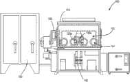
图3为用于组装图1的近端股骨构件的示例性设备的前正视图;3 is a front elevational view of an exemplary device for assembling the proximal femoral component of FIG. 1;
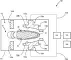
图4A为图3的设备的示意图,所述设备包括固定装置和焊接头,所述固定装置和焊接头在接收近端股骨构件的打开位置中示出;Fig. 4 A is the schematic diagram of the apparatus of Fig. 3, described apparatus comprises fixing device and welding head, and described fixing device and welding head are shown in the open position that receives proximal end femoral component;
图4B为与图4A类似的示意图,所述设备的固定装置和焊接头在将多孔金属层抵靠着近端股骨构件的金属基体保持的闭合位置中示出;Figure 4B is a schematic view similar to Figure 4A, with the fixture and welding head of the device shown in a closed position with the porous metal layer held against the metal matrix of the proximal femoral component;
图5为依照实施例1的各种多孔层与金属基体之间的平均结合强度的图示性绘图;5 is a graphical plot of the average bond strength between various porous layers and metal substrates according to Example 1;
图6为依照实施例2的各种多孔层与金属基体之间的平均结合强度的另一图示性绘图;6 is another graphical plot of the average bond strength between various porous layers and metal substrates according to Example 2;
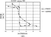
图7为依照实施例3的各种多孔层与金属基体之间的结合强度的图示性绘图;7 is a graphical plot of bond strength between various porous layers and metal substrates according to Example 3;
图8为扩散结合样本和电阻焊接样本中钽浓度梯度的图示性绘图;Figure 8 is a graphical plot of tantalum concentration gradients in diffusion bonded samples and resistance welded samples;
图9为扩散结合样本和电阻焊接样本中钽浓度梯度的图示性绘图;Figure 9 is a graphical plot of tantalum concentration gradients in diffusion bonded and resistance welded samples;
图10为沿着扩散结合样本的多孔构件与基体之间的分界面获得的扫描电子显微镜影像;10 is a scanning electron microscope image obtained along the interface between the porous member and the matrix of the diffusion bonded sample;
图11为沿着电阻焊接样本的多孔构件与基体之间的分界面获得的扫描电子显微镜影像;Figure 11 is a scanning electron microscope image obtained along the interface between the porous member and the substrate of the resistance welded sample;
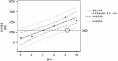
图12为依照实施例6的各种多孔层与金属基体之间的结合强度的另一图示性绘图;12 is another graphical plot of bond strength between various porous layers and metal substrates according to Example 6;
图13为沿着依照实施例6的多孔层与金属基体之间的分界面获得的扫描电子显微镜影像;13 is a scanning electron microscope image obtained along the interface between the porous layer and the metal substrate according to Example 6;
图14为沿着依照实施例7的多孔层与金属基体之间的分界面获得的扫描电子显微镜影像;14 is a scanning electron microscope image obtained along the interface between the porous layer and the metal substrate according to Example 7;
图15为依照实施例7的各种多孔层与金属基体之间的结合强度的另一图示性绘图。15 is another graphical plot of bond strength between various porous layers and metal substrates according to Example 7. FIG.
几个视图从头到尾相同的参考标号代表相同的部件。此处展现的示例图示出了本发明示例性实施例,并且这些示例不以任何方式构成对本发明范围的限定。Like reference numerals represent like parts throughout the several views. The examples presented herein illustrate exemplary embodiments of the invention and are not intended to limit the scope of the invention in any way.
具体实施方式Detailed ways
参照图1和图2,提供形式为近端股骨构件10(例如髋骨柄)的整形假体。虽然这里描述和图绘了近端股骨构件10形式的整形假体,但是整形假体也可以是例如远端股骨构件、胫骨构件、髋臼构件或肱骨构件的形式。Referring to Figures 1 and 2, an orthopedic prosthesis in the form of a proximal
图1的近端股骨构件10包括柄部12和颈部14,所述颈部构造成接收模块化头部(未示出)。同样属于本申请范围内的是该头部可以一体连接至颈部14。在使用中,通过将近端股骨构件10的柄部12植入患者近端股骨的髓腔,近端股骨构件10的颈部14和头部(未示出)从患者的近端股骨居中地延伸以与患者的天然髋臼或假体的髋臼构件关节连接。近端股骨构件10的柄部12包括外骨接触表面18,其构造成接触患者股骨的骨头和/或软组织。The proximal
如图2中所示,近端股骨构件10包括金属基体20以及多孔金属层22,所述多孔金属层22连接至位于其下的基体20的。多孔层22可安置在基体20的凹部26中。通过多孔层22限定了骨接触表面18的至少一部分,久而久之患者股骨的骨头和/或软组织可以生长进入多孔层22以增强近端股骨构件10与患者股骨之间的固定(即骨整合)。As shown in FIG. 2 , the proximal
近端股骨构件10的基体20可包括诸如钛、钛合金、钴铬、钴铬钼、钽或钽合金的生物相容性金属。根据本发明的示例性实施例,基体20包括Ti-6Al-4V ELI合金,例如能从Indiana州Warsaw的Zimmer公司得到的

近端股骨构件10的多孔层22可包括诸如钛、钛合金、钴铬、钴铬钼、钽或钽合金的生物相容性金属。多孔层22可以是高度多孔生物材料的形式,这作为骨替代物以及细胞和软组织接受材料是有用的。同样处于本发明范围内的是,例如,多孔层22可以是纤维金属垫或诸如Cancellous-Structured TitaniumTM(CSTiTM)层的烧结金属层的形式。CSTiTM多孔层由Indiana州Warsaw的Zimmer公司制造。Cancellous-Structured TitaniumTM和CSTiTM是Zimmer公司的商标。
高度多孔生物材料可具有低到55%、65%或75%和高到80%、85%或90%,或者处于前述值任一配对之间所限定的任意范围内的孔隙率。这样的材料的例子为高度多孔的纤维金属垫。这样的材料的又一例子为CSTiTM层。这样的材料的另一例子使用大体可从Indiana州Warsaw的Zimmer公司得到的Trabecular MetalTM技术生产。Trabecular MetalTM是Zimmer公司的商标。这样的材料可以由网形的玻璃碳泡沫基体形成,通过在美国专利No.5,282,861中以详细方式公开的化学气相沉积(“CVD”)工艺,该基体采用诸如钽的生物相容性金属渗透和涂覆,该专利公开文献通过引用被清楚地结合于此。除了钽之外,也可以使用其他诸如铌的金属或者钽和铌彼此的、或钽和铌与其他金属的合金。A highly porous biomaterial may have a porosity as low as 55%, 65% or 75% and as high as 80%, 85% or 90%, or within any range defined between any pair of the preceding values. An example of such a material is a highly porous fibrous metal mat. Yet another example of such a material is a layer of CSTi™ . Another example of such a material is produced using Trabecular Metal(TM) technology generally available from Zimmer Corporation of Warsaw, Indiana. Trabecular Metal™ is a trademark of Zimmer Corporation. Such materials may be formed from a matrix of reticulated glassy carbon foam infiltrated with a biocompatible metal such as tantalum and coating, this patent publication is expressly incorporated herein by reference. Besides tantalum, other metals such as niobium or alloys of tantalum and niobium with each other or with other metals can also be used.
大体上,多孔钽结构包括大量的纤维(ligament),纤维限定了位于其间的开放空间,各纤维大体上例如包括由诸如钽的金属薄膜覆盖的碳芯。纤维之间的开放空间形成了没有尽头的连续通道基质(matrix),使得松质骨经过多孔钽结构的生长是不受抑制的。多孔钽在其中可包括高达75%-85%或更多的空隙空间。因而多孔钽是轻重量的、强力的多孔结构,所述多孔结构在组分上大体上统一和一致,并且酷似天然松质骨的结构,从而设置了松质骨可生长到其中的基质以提供近端股骨构件10至患者股骨的固定。In general, porous tantalum structures comprise a multitude of ligaments defining open spaces therebetween, each fiber generally comprising, for example, a carbon core covered by a thin film of metal such as tantalum. The open spaces between the fibers form an endless matrix of continuous channels, allowing the growth of cancellous bone through the porous tantalum structure to be uninhibited. Porous tantalum can include as much as 75%-85% or more void space therein. Porous tantalum is thus a lightweight, strong porous structure that is substantially uniform and consistent in composition and mimics that of natural cancellous bone, thereby providing a matrix into which cancellous bone can grow to provide Fixation of the proximal
为了选择性地为特定应用订制结构,多孔钽结构可以以不同的密度制成。尤其如以上结合的美国专利No.5,282,861中所述的,多孔钽可制造成实质上任何所想要的孔隙率和孔隙尺寸,并且因而能够与周围的天然骨骼相匹配以便为骨骼向内生长和矿化提供最优化的基质。Porous tantalum structures can be fabricated in different densities in order to selectively tailor the structure for specific applications. Porous tantalum can be fabricated to virtually any desired porosity and pore size, and thus can be matched to the surrounding natural bone to provide for bone ingrowth and Mineralization provides an optimized matrix.
当近端股骨构件10的多孔层22采用如上所述的TrabecularMetalTM技术生产时,小百分比率的基体20可与多孔层22的纤维直接接触。例如基体20的表面积的近似15%、20%或25%可与多孔层22的纤维直接接触。When the
接下来参照图3,提供设备100以用于将多孔层22电阻焊接至近端股骨构件10的基体20。设备100在图4A和图4B中也示意地示出。设备100包括壳体110,在壳体110内包括一个或多个支架或固定装置120a、120b,一个或多个焊接头130a、130b,各个焊接头具有电极132a、132b;所述设备包括变压器140、电源或电流发生器150以及控制器160。设备100的各构件进一步在以下描述。Referring next to FIG. 3 , an
设备100的壳体110限定了内部腔室112,所述内部腔室尺寸被设置为接收至少一个诸如图1和图2的近端股骨构件10的假体。根据本发明的示例性实施例,在电阻焊接过程期间,设备100的壳体110在腔室112中制造了真空环境或惰性环境。在一特别的实施例中,壳体110的腔室112充入惰性气体(例如氩气)并且控制成具有约-60°C以下的露点以及约10ppm以下的氧气浓度。
壳体110可以至少部分地透明以使得使用者能看见腔室112内部。壳体110也可以包括一个或多个开口114以使得使用者能进入腔室112。为了保持腔室112中的真空环境或惰性环境,壳体110可以是手套箱的形式。换句话说,各个开口114可以包括手套件(未示出)或其他适合的屏障物,所述手套件或屏障物延伸进入腔室112以接收使用者的手同时保持开口114周围的密封。
设备100的固定装置120a、120b接触近端股骨构件10以将近端股骨构件10在设备100的壳体110中保持就位。固定装置120a、120b可分开地移动至打开位置(图4A)以接收近端股骨构件10,并且向一起移动到闭合或夹持位置(图4B)以将近端股骨构件10保持就位。属于本发明范围内的是固定装置120a、120b的闭合位置可以调节以使得设备100能接收和保持不同形状和尺寸的假体。The
设备100的焊接头130a、130b上的电极132a、132b分别经由电线152a、152b连接至变压器140和电流发生器150。如图4A中所示,各电极132a、132b朝向多孔层22的对应侧。更具体地,各电极132a、132b的接触表面134a、134b朝向多孔层22的对应侧。根据本发明的示例性实施例,各电极132a、132b的接触表面134a、134b设计成大体上与多孔层22的相应侧的轮廓相匹配。在该实施例中,各电极132a、132b能被使得靠近、甚至接触近端股骨构件10。取决于近端股骨构件10的形状,相应的轮廓表面134a、134b可以例如是凹的、凸的或平坦的。
设备100的焊接头130a、130b可构造成在电阻焊接过程期间抵靠基体20保持多孔层22。更具体地,焊接头130a、130b可构造成在电阻焊接过程期间将多孔层22保持在基体20的凹部26中。类似上述的固定装置120a、120b,焊接头130a、130b可以远离近端股骨构件10移动到打开位置(图4A)以接收近端股骨构件10,并且然后焊接头130a、130b可以朝着近端股骨构件10移动到闭合或夹持位置(图4B)以将多孔层22保持在基体20的凹部26中。焊接头130a、130b的打开和/或闭合位置可以采用一个或多个止挡件136a、136b控制,所述止挡件与焊接头130a、130b上相应的凸缘138a、138b接触以限制电极132a、132b的运动。属于本发明范围内的是各焊接头130a、130b的闭合位置可以例如通过移动止挡件136a、136b调节以使得设备100能够接收和保持不同形状和尺寸的假体。The welding heads 130a, 130b of the
可选地,设备100可包括附加的支架或固定装置(未示出),所述支架或固定装置构造成在电阻焊接过程期间抵靠基体20保持多孔层22。更特别地,这些附加的固定装置可以构造成在电阻焊接过程期间将多孔层22保持在基体20的凹部26中。Optionally,
在电阻焊接过程期间所使用的抵靠近端股骨构件10的基体20保持多孔层22的压力可足够地低以避免多孔层22变形或压缩同时仍阻碍多孔层22相对于基体20的运动。因而,焊接压力应当不超过基体20或多孔层22的压缩屈服强度。例如,如果多孔层22的压缩屈服强度为大约4000psi(27.6MPa),那么适合的焊接压力可以例如低到100psi(0.7MPa)、500psi(3.4MPa)或1000psi(6.9MPa),和高到2000psi(13.8Mpa)、2500psi(17.2MPa)或3000psi(20.7MPa),或者处于前述值任一配对之间所限定的任意范围内。多孔层22可以在电阻焊接过程之前设成大体最终的形状以避免在电阻焊接过程期间不得不压缩或以其他方式使多孔层22成型。结果,多孔层22的厚度以及多孔层22与基体20之间的接触面积在电阻焊接过程期间可大体上保持不变。如上所述,当焊接头130a、130b处于闭合位置(图4B)时,焊接压力可由焊接头130a、130b施加和/或由设备100附加的固定装置(未示出)施加。The pressure used to hold the
设备100的、可以为通用计算机形式的控制器160连接到变压器140和电流发生器150以控制电极132a、132b的操作。设备100的控制器160也可以控制壳体110的抽空和/或以惰性气体(例如氩气)充入壳体110。附加地,设备100的控制器160可控制固定装置120a、120b和/或焊接头130a、130b在它们各自的打开位置(图4A)与闭合位置(图4B)之间的运动。A
在使用中,近端股骨构件10被装载到设备100的壳体110中。随着多孔层22适当地抵靠近端股骨构件10的基体20安置,控制器160可被操作以将固定装置120a、120b和/或焊接头130a、130b从它们各自的打开位置(图4A)朝着它们各自的闭合位置(图4B)移动。接近压力(即,固定装置120a、120b和/或焊接头130a、130b与近端股骨构件10相接触之前接近近端股骨构件10的压力)可以小于上述焊接压力以避免损坏构件。例如,接近压力可以低到10psi(0.07MPa)、30psi(0.2MPa)或50psi(0.3MPa)和高到70psi(0.5MPa)、90psi(0.6MPa)或110psi(0.8MPa),或者处于前述值任一配对之间所限定的任意范围内。In use, the proximal
在近端股骨构件10被装载到设备100的壳体110中之后,控制器160可被操作以抽空壳体110的腔室112和/或以惰性气体(例如氩气)充入壳体110的腔室112。设备100的壳体110中的真空或惰性环境可大体上防止近端股骨构件10在电阻焊接过程期间氧化、吸收大气污染物和/或变得褪色。After the proximal
控制器160然后可继续将固定装置120a、120b和焊接头130a、130b移动到它们各自的闭合位置(图4B)中以将近端股骨构件10的多孔层22和基体20都在壳体110中保持就位。如上所述,焊接压力(即电阻焊接过程期间固定装置120a、120b和/或焊接头130a、130b达到保持近端股骨构件10时的压力)可以例如低到100psi(0.7MPa)、500psi(3.4MPa)或1000psi(6.9MPa)和高到2000psi(13.8MPa)、2500psi(17.2MPa)或3000psi(20.7MPa)。The
接下来,控制器160可被操作以引起电流从电流发生器150流至变压器140。电流发生器150可例如以4kJ、6kJ、8kJ、10kJ或更大的功率操作。随着各电极132a、132b的接触表面134a、134b抵靠近端股骨构件10的多孔层22定位,焊接电流从一个电极(例如经由电线152a从电极132a)流经近端股骨构件10,并从另一电极(例如经由电线152b从电极132b)流出。在示例性实施例中,源电极132a、132b可将例如低到20kA、30kA或40kA和高到50kA、60kA或70kA,或者处于前述值任一配对之间所限定的任意范围内的焊接电流输送至近端股骨构件10,以产生低到25kA/in2(3.9kA/cm2)、35kA/in2(5.4kA/cm2)或45kA/in2(7.0kA/cm2)和高到55kA/in2(8.5kA/cm2)、65kA/in2(10.1kA/cm2)、75kA/in2(11.6kA/cm2)或85kA/in2(13.2kA/cm2),或者处于前述值任一配对之间所限定的任意范围内的焊接电流密度。当焊接电流流经近端股骨构件10时,控制器160可保持固定装置120a、120b和/或焊接头130a、130b的焊接压力。Next, the
根据欧姆定律(P=I2*R),流经近端股骨构件10的多孔层22和基体20的焊接电流I作为热量散发,伴随着在电路中的任意点处产生的热量与电阻R成比例。当采用不同的材料构建多孔层22和基体20时,电阻R在多孔层22与基体20之间的分界面处可以是最高的。因此,在多孔层22与基体20之间的接触点处可局部地产生大量的热量。According to Ohm's law (P=I2 *R), the welding current I flowing through the
根据本发明的示例性实施例,产生的热量足以引起用于构建多孔层22和/或基体20的材料的软化和/或热熔,结合用于抵靠基体20保持多孔层22的焊接压力,所述软化和/或热熔使得在多孔层22与基体20之间的接触点处发生表面冶金结合。同样属于本发明范围的是冶金结合可在多孔层22内的接触点处发生。例如,如果多孔层22形式为纤维金属垫,那么冶金结合可在纤维金属垫中相邻金属线之间的接触点处发生。According to an exemplary embodiment of the present invention, the heat generated is sufficient to cause softening and/or melting of the material used to construct the
根据本发明的又一示例性实施例,焊接电流可在离散但迅速的脉冲中输送至近端股骨构件10。焊接电流可以例如以少到4、6或8个脉冲和多到10、12或14个脉冲、或以任何其间数值的脉冲输送至近端股骨构件10。各脉冲可例如短到20毫秒、40毫秒或60毫秒和长到80毫秒、100毫秒或120毫秒、或任何其间的数值。在每个脉冲之间,焊接电流的缺失可以以不消除多孔层22和基体20的局部的、分界面上热量的方式促进多孔层22和基体20的大量冷却。各脉冲之间的冷却时间可少于1秒,并且更具体地可例如短到20毫秒、40毫秒或60毫秒和长到80毫秒、100毫秒或120毫秒、或任何其间的数值。According to yet another exemplary embodiment of the present invention, welding current may be delivered to the proximal
如上所述,在电阻焊接过程期间用于抵靠基体20保持多孔层22的焊接压力应当充分地低以避免多孔层22变形。由于基体20沿着分界面的软化和/或热熔,多孔层22可朝着软化的基体20略微地移动或平移并且可变得嵌进软化的基体20中。因此,近端股骨构件10的总厚度(即多孔层22和基体20的结合厚度)在电阻焊接过程期间可降低。例如,在电阻焊接过程期间,近端股骨构件10的总厚度可降低近似0.1%、0.2%、0.3%或更多。然而,多孔层22本身的厚度不应当显著地改变。换句话说,近端股骨构件10厚度上的任何可测量到的改变应当由多孔层22移动到软化的基体20中而引起,而不是由多孔层22本身的压缩或变形而引起。当多孔层22形式为纤维金属垫时,由于多孔层22中形成冶金结合,所以多孔层22可承受某种变形(例如皱缩)。然而,该变形不应当归因于焊接压力。As mentioned above, the welding pressure used to hold the
在将电流输送至近端股骨构件10之后,基体20和多孔层22将开始冷却。在此期间,控制器160可被操作以保持构件上的锻造压力。锻造压力(即在焊接电流结束之后,固定装置120a、120b和/或焊接头130a、130b保持近端股骨构件10的压力)可比上述焊接压力小。例如,锻造压力可低到40psi(0.3MPa)、60psi(0.4MPa)或80psi(0.6MPa)和高到100psi(0.7MPa)、120psi(0.8MPa)或140psi(1.0MPa),或者处于前述值任一配对之间所限定的任意范围内。锻造时间可例如短到1秒、2秒或3秒和长到4秒、5秒或更多。After delivery of electrical current to the proximal
总体来讲,采用设备100将多孔层22电阻焊接至基体20所需的时间例如可短到1秒、10秒、20秒或30秒和长到1分钟、2分钟、3分钟或更多。取决于多孔层22的厚度、由电流发生器产生的电流、以及其他参数,所需的时间可变化。In general, the time required to resistance weld
最后,控制器160可被操作以将固定装置120a、120b和/或焊接头130a、130b返回至它们各自的打开位置(图4A)。近端股骨构件10随后可以以多孔层22牢固地固定至基体20的方式从设备100的壳体110移除。Finally, the
有利的是,通过将多孔层22电阻焊接至基体20上,在多孔层22与基体20之间可实现坚固的冶金结合。在特定的实施例中,多孔层22与基体20之间的结合强度可至少为2900psi(20.0MPa),该结合强度为FDA推荐的用于整形植入的结合强度。而且,因为电阻焊接包含多孔层22和基体20的局部的、分界面上的加热并且需要短的循环时间,所以多孔层22和基体20的劣化可以避免。结果,在电阻焊接过程期间,基体20和多孔层22的疲劳强度可大体上没有改变。Advantageously, by resistance welding
尽管多孔层22在此描述和描绘成直接结合至近端股骨构件10的基体20,然而也属于本发明范围的是多孔层22可预先结合至中间层(未示出),所述中间层随后结合至基体20。适合的中间层可例如包括钛箔。多孔层22与中间层之间的预结合步骤以及中间层与基体20之间随后的结合步骤均可包含参照图3、图4A和图4B的上述电阻焊接。然而,也属于本发明范围的是随后的中间层与基体20之间结合步骤可包含传统的扩散结合。Although the
实施例Example
1.实施例1—Trabecular MetalTM表面精饰和厚度的分析1. Analysis of embodiment 1—Trabecular Metal™ surface finish and thickness
准备了一系列样品,各样品具有使用Trabecular MetalTM技术生产的盘状多孔构件和盘状的
表1Table 1

在将各多孔构件的分界表面抵靠其相应的基体放置之前,各多孔构件的分界表面如以上表1中所列的进行处理。The interface surface of each porous member was treated as listed in Table 1 above, prior to placing the interface surface of each porous member against its corresponding substrate.
在组1中,各多孔构件的分界表面经受放电加工(EDM),其折断多孔构件的一些突出纤维并且使分界表面平整,使得在分离表面处更多可用的纤维接触在下面的基体。因此,EDM适度地增加了组1中多孔构件的净接触面积。In set 1, the interface surface of each porous member was subjected to electrical discharge machining (EDM), which broke some of the protruding fibers of the porous member and smoothed the interface surface so that more fibers were available at the separation surface to contact the underlying matrix. Thus, EDM modestly increased the net contact area of the porous members in Group 1.
在组2中,各多孔构件设成网形(net shape)并且在制造之后各多孔构件的分界表面没有经受加工,所以在分界表面处保持了多孔构件的容积孔隙率。更具体地,网状的分界表面通过以金属涂覆多孔结构(即网状的玻璃碳泡沫结构)的外表面并且随后以不对外表面加工或成型的方式保持外部的、涂覆的表面来生产。因此,组2中多孔构件的净接触面积得以保留。In group 2, each porous member was set in a net shape and the boundary surface of each porous member was not subjected to processing after manufacture, so the volumetric porosity of the porous member was maintained at the boundary surface. More specifically, the reticulated interface surface is produced by metal-coating the outer surface of the porous structure (i.e. reticulated glassy carbon foam structure) and then maintaining the outer, coated surface in such a way that the outer surface is not machined or shaped . Therefore, the net contact area of the porous members in Group 2 is preserved.
在组3中,各多孔构件的分界表面经受物理加工以折断多孔构件的一些纤维并且展开或“涂抹”多孔构件的其他纤维,这导致分界表面的表面孔隙率的显著减少。因此,涂抹增加了组3中多孔构件的净接触面积。In Group 3, the interface surface of each porous member was subjected to physical processing to break some fibers of the porous member and spread or "smear" other fibers of the porous member, which resulted in a significant reduction in the surface porosity of the interface surface. Therefore, smearing increased the net contact area of the porous members in Group 3.
这些表面处理的结果在于,组2的多孔构件具有与在下面的基体最少的表面接触,而组3的多孔构件具有与在下面的基体最多的表面接触。As a result of these surface treatments, the porous members of group 2 had the least surface contact with the underlying substrate, while the porous members of group 3 had the most surface contact with the underlying substrate.
样品随后通过电阻焊接组装。施加第一量级的功率以将0.060英寸(1.5mm)厚和0.125英寸(3.2mm)厚的多孔构件(组1A、1B、2A、2B、3A和3B)焊接到它们相应的基体上。施加比第一量级功率大50%的第二量级功率以将0.250英寸(6.4mm)厚的多孔构件(组1C、2C和3C)焊接到它们相应的基体上。各组1-3的样品的平均结合强度在图5中图示性地绘出。The samples were then assembled by resistance welding. A first level of power was applied to weld the 0.060 inch (1.5 mm) thick and 0.125 inch (3.2 mm) thick porous members (
如图5中所示,组2的样品相比组1或组3的样品具有更高的平均结合强度。因为组1和组3的多孔构件相比组2的样品具有更多的与在下面的基体的表面接触,所以发明人怀疑跨过更大表面接触面积所施加的电流和散失的热量导致了对于组1和组3的样品而言相比组2样品更弱的结合。相反地,因为组2的多孔构件相比组1和组3的样品具有更少的与在下面的基体的表面接触,所以发明人怀疑施加的电流和在各分别的纤维处局部化的热量导致了对于组2的样品而言相比组1和组3的样品更强的结合。As shown in FIG. 5 , the samples of Group 2 had a higher average binding strength than the samples of Group 1 or Group 3 . Because the porous members of Groups 1 and 3 had more surface contact with the underlying substrate than the samples of Group 2, the inventors suspected that the applied current and dissipated heat across the larger surface contact area contributed to the Group 1 and Group 3 samples showed weaker binding than Group 2 samples. Conversely, because the porous members of Group 2 had less surface contact with the underlying substrate than the samples of Groups 1 and 3, the inventors suspected that the applied current and the localized heat at each respective fiber caused Stronger binding was observed for Group 2 samples compared to Group 1 and Group 3 samples.
而且,在各个组1-3中,子组A和C的样品相比相应子组B的样品具有更高的平均结合强度。例如,组2A和组2C的样品相比组2B的样品具有更高的平均结合强度。Also, in each of groups 1-3, samples from subgroups A and C had higher average binding strengths than samples from the corresponding subgroup B. For example, the samples of
在各个组1-3中从子组A至B结合强度的降低可归因于多孔构件从0.060英寸到0.125英寸所增加的厚度。因为在各多孔构件中钽的导热率(大约54W/m/K)大于各基体中钽的导热率(大约7W/m/K),所以各子组B的更厚的多孔构件可充当散热器,将在分界面产生的热量传导远离分界面并且传导进多孔构件的空间中。The decrease in bond strength from subgroups A to B in each of groups 1-3 is attributable to the increased thickness of the porous member from 0.060 inches to 0.125 inches. Because the thermal conductivity of tantalum in each porous member (approximately 54 W/m/K) is greater than that of tantalum in each matrix (approximately 7 W/m/K), the thicker porous members of each subgroup B act as heat sinks , conduct the heat generated at the interface away from the interface and into the space of the porous member.
在各个组1-3中从子组B至C结合强度的增加可归因于用于电阻焊接0.060英寸厚和0.125英寸厚的多孔构件的第一量级功率与用于电阻焊接0.250英寸厚的多孔构件的第二量级功率之间50%的增加。增加的功率产生了增加的电流,其导致更大的发热和更强的结合。The increase in bond strength from subgroups B to C in each of groups 1-3 can be attributed to the first order of magnitude power used for resistance welding 0.060 inch thick and 0.125 inch thick porous members compared to resistance welding 0.250 inch thick A 50% increase between the second magnitude power of the porous member. Increased power produces increased current, which results in greater heating and stronger bonding.
2.实施例2—Trabecular MetalTM厚度、焊接功率以及焊接循环次数的分析2. The analysis of embodiment 2—Trabecular MetalTM thickness, welding power and number of welding cycles
准备了另外一系列样品,各样品具有使用Trabecular MetalTM技术生产的盘状多孔构件和盘状的
表2Table 2

各个组4-6的样品的平均结合强度在图6中图示性地绘出。组4和组6的样品相比组5的样品具有更高的平均结合强度。其实,组4和组6的样品具有4000psi(27.6MPa)以上的平均结合强度,该平均结合强度超过了FDA推荐的2900psi(20.0MPa)的结合强度。The average binding strength of samples from each of Groups 4-6 is plotted graphically in FIG. 6 . Group 4 and
结合强度中变化的大约90.6%可归因于多孔构件变化的厚度以及变化的焊接功率。发现焊接循环的次数在统计上显得无关紧要。Approximately 90.6% of the variation in bond strength can be attributed to the varying thickness of the porous member as well as the varying welding power. The number of welding cycles was found to be statistically insignificant.
3.实施例3—Trabecular MetalTM厚度和焊接时间的分析3. The analysis of embodiment 3—Trabecular MetalTM thickness and welding time
准备了另外一系列的圆形样品,各样品具有使用TrabecularMetalTM技术生产的盘状多孔构件和盘状的
表3table 3
在电阻焊接所述样品之后,从各样品上切下两个1.2英寸(3.0cm)直径的试样以用于拉伸测试。组7和组8的各试样的结合强度在图7中图示性地绘出。如图7中所示,组8B的两个试样的其中一个具有比FDA推荐的2900psi(20.0MPa)的结合强度更大的结合强度。然而,组8B的另一个试样具有1000psi(6.9MPa)以下的结合强度。After resistance welding the samples, two 1.2 inch (3.0 cm) diameter specimens were cut from each sample for tensile testing. The bond strength of each sample of
相应试样之间的结合强度的变化可能由于经过各样品的非均匀的压力和/或电流。在切掉1.2英寸(3.0cm)直径的试样之后留下的残留材料的物理检测证实了各样品中结合强度变化等级的发现。Variations in bond strength between corresponding samples may be due to non-uniform pressure and/or current passing through the samples. Physical examination of the residual material left after cutting away 1.2 inch (3.0 cm) diameter specimens confirmed the finding of varying degrees of bond strength among the samples.
4.实施例4—电阻焊接与扩散结合之间的比较4. Example 4—Comparison between Resistance Welding and Diffusion Bonding
除了拉伸测试之外,也执行了金相学测试以比较通过电阻焊接实现的结合和通过扩散结合实现的结合。In addition to tensile testing, metallographic testing was also performed to compare the bonding achieved by resistance welding with that achieved by diffusion bonding.
当多孔构件扩散结合至在下面的基体时,来自多孔构件的原子与来自基体的原子相互扩散。例如,当采用Trabecular MetalTM技术生产的多孔构件扩散结合到
当多孔构件被电阻焊接至在下面的基体时,很少发生或不发生相互扩散。例如,在图8中多孔构件中的钽浓度大体保持恒定,并且在图9中基体中的钛浓度大体保持恒定。多孔构件与基体之间的任何显著的相互扩散层的缺失在图11中也可见地示出,该图为沿着电阻焊接样品的多孔构件与基体之间分界面获得的扫描电子显微镜影像。When the porous member is resistance welded to the underlying substrate, little or no interdiffusion occurs. For example, the concentration of tantalum in the porous member remains substantially constant in FIG. 8 and the concentration of titanium in the matrix remains substantially constant in FIG. 9 . The absence of any significant interdiffusion layer between the porous member and the substrate is also visible in Figure 11, which is a scanning electron microscope image taken along the interface between the porous member and the substrate of the resistance welded samples.
5.实施例5—焊接压力的分析5.
准备了一系列直径为1英寸(2.5cm)的盘状样品,各样品的电极分界面具有约0.79平方英寸(5.1cm2)的表面积。各样品具有0.055英寸(1.4mm)厚度的、采用Trabecular MetalTM技术生产的多孔构件以及0.130英寸(3.3mm)厚度的基体。焊接压力计算为4160psi(28.7MPa),其可与多孔构件的压缩屈服强度相比。该高焊接压力的结果是,在焊接期间多孔构件部分地受挤压并且平均厚度减少约0.022英寸(0.6mm)或减少40%(从0.055英寸(1.4mm)至0.033英寸(0.8mm))。A series of 1 inch (2.5 cm) diameter disk samples were prepared, each having an electrode interface having a surface area of about 0.79 square inches (5.1cm² ). Each sample had a 0.055 inch (1.4 mm) thick porous member produced using Trabecular MetalTM technology and a 0.130 inch (3.3 mm) thick matrix. The weld pressure was calculated to be 4160 psi (28.7 MPa), which is comparable to the compressive yield strength of the porous member. As a result of this high weld pressure, the porous member was partially compressed and the average thickness was reduced by about 0.022 inches (0.6 mm) or 40% (from 0.055 inches (1.4 mm) to 0.033 inches (0.8 mm)) during welding.
6.实施例6—脉冲焊接的分析6.
准备了另外一系列直径为1英寸(2.5cm)的盘状样品,各样品具有0.055英寸(1.4mm)厚度的、采用Trabecular MetalTM技术生产的多孔构件以及0.130英寸(3.3mm)厚度的
表4Table 4
如以下在表5中列出的,各样品接收不同数量的焊接电流脉冲,各脉冲持续80毫秒并且各脉冲之间的冷却时间持续80毫秒。样品1-5被准备以预估高达10个脉冲。样品6-11被准备以更具体地预估5个和10个之间的脉冲。As listed below in Table 5, each sample received a different number of welding current pulses, each pulse lasting 80 milliseconds and a cooling time between pulses lasting 80 milliseconds. Samples 1-5 were prepared to estimate up to 10 pulses. Samples 6-11 were prepared to more specifically estimate between 5 and 10 pulses.
表5table 5
设计和建造一种新型的电阻焊接设备以在受控的环境中输送这些焊接电流脉冲。所述设备包括具有BMI-500单柱气体净化系统的AX5000大气封闭装置、具有冷却的铜合金电极的KN-Ⅱ突出焊接头、IT-1400-3变压器以及ISA-2000CR逆变电源,所有这些可从California州Monrovia的Miyachi Unitek公司得到。A new type of resistance welding equipment was designed and built to deliver these welding current pulses in a controlled environment. The equipment includes AX5000 atmospheric enclosure with BMI-500 single-column gas purification system, KN-II protruding welding head with cooled copper alloy electrodes, IT-1400-3 transformer, and ISA-2000CR inverter power supply, all of which can Obtained from Miyachi Unitek, Monrovia, California.
各样品的总体厚度在焊接之前和之后大体上保持相同,表明实施例5的较低的800psi(5.5MPa)的焊接压力成功地消除了以上在实施例4中所见的多孔构件的扭曲和挤压。The overall thickness of each sample remained substantially the same before and after welding, indicating that the lower welding pressure of Example 5 of 800 psi (5.5 MPa) successfully eliminated the twisting and pinching of the porous member seen above in Example 4. pressure.
样品1-5经受拉伸测试。焊接部的结合强度从对于样品1(1个脉冲)的0psi(0MPa)增加至对于样品3(6个脉冲)的6882psi(47.4MPa)。对于样品4(8个脉冲)和样品5(10个脉冲)而言焊接部的结合强度保持近似相同。Samples 1-5 were subjected to tensile testing. The bond strength of the weld increased from 0 psi (0 MPa) for sample 1 (1 pulse) to 6882 psi (47.4 MPa) for sample 3 (6 pulses). The bond strength of the weld remained approximately the same for Sample 4 (8 pulses) and Sample 5 (10 pulses).
样品6-11随后经受拉伸测试和回归分析,其结果在图12中图示性地绘出。如图12中所示,结合强度伴随着每个附加的脉冲增加。较低的95%预测区间在9个焊接脉冲之上与2900psi(20.0MPa)参考线相交(见图12中环形交叉点)。因而,对于给定的焊接参数,需要至少10个焊接脉冲以持续地产生至少2900psi的结合强度。Samples 6-11 were then subjected to tensile testing and regression analysis, the results of which are plotted graphically in FIG. 12 . As shown in Figure 12, the binding strength increased with each additional pulse. The lower 95% prediction interval intersects the 2900 psi (20.0 MPa) reference line above 9 welding pulses (see circular intersection in Figure 12). Thus, for given welding parameters, at least 10 welding pulses are required to consistently produce a bond strength of at least 2900 psi.
样品的可视化检验展现出既沿着结合分界面(即多孔构件与基体之间的分界面)又沿着电极分界面(即样品与电阻焊接电极之间的分界面)形成能注意到的热影响区。由于在电阻焊接过程期间产生的热量,所以样品在这样的热影响区中可经历扭曲、渗透和/或微结构改变。例如,图13图绘出沿着以上样品1的结合分界面形成的热影响区。可能的并且属于本发明范围的是在电阻焊接过程之后将电极分界面加工掉或以其他方式去除。然而,在电阻焊接过程之后不能以不毁坏结合的方式去除结合分界面。Visual inspection of the sample exhibits noticeable thermal effects along both the bonding interface (i.e., the interface between the porous member and the substrate) and along the electrode interface (i.e., the interface between the sample and the resistance welding electrode) district. Due to the heat generated during the resistance welding process, samples may undergo distortion, infiltration, and/or microstructural changes in such a heat-affected zone. For example, Figure 13 depicts the heat affected zone formed along the bonding interface of Sample 1 above. It is possible and within the scope of the invention to machine or otherwise remove the electrode interface after the resistance welding process. However, the bond interface cannot be removed after the resistance welding process without destroying the bond.
7.实施例7—针对网形的多孔构件为减少热影响区的脉冲焊接电流的分析7. Example 7—Analysis of the pulse welding current for reducing the heat-affected zone for mesh-shaped porous members
为了消除以上在实施例6中所见的热影响区,准备了另外一系列直径为1英寸(2.5cm)的盘状样品,各样品具有0.055英寸(1.4mm)厚度的、采用Trabecular MetalTM技术生产的多孔构件以及0.130英寸(3.3mm)厚度的
表6Table 6
如以下在表7中所列出的,所述样品接收35kA与51kA之间的脉冲焊接电流。As listed below in Table 7, the samples received a pulsed welding current between 35 kA and 51 kA.

作为初始的物质,样品的可视化检验显示了沿着结合分界面的热影响区的宽度和范围相比于实施例6显著地降低或者在一些情况下完全消除。例如,实施例6的样品1(图13)相比实施例7的样品3b(图14)具有能注意到的更大的热影响区。一些热影响区沿着电极分界面保留,但是如上所述,可以在电阻焊接过程之后将这些电极分界面加工掉或以其他方式去除。As with the original material, visual inspection of the samples showed that the width and extent of the heat-affected zone along the bonding interface was significantly reduced or in some cases completely eliminated compared to Example 6. For example, Sample 1 of Example 6 (Figure 13) has a noticeably larger heat affected zone than Sample 3b of Example 7 (Figure 14). Some heat-affected zones remain along the electrode interfaces, but as noted above, these electrode interfaces may be machined or otherwise removed after the resistance welding process.
样品同样经受拉伸测试和回归分析,其结果在图15中图示性地示出。如图15中所示,当每个脉冲的焊接电流增加时结合强度增加。较低的95%预测区间在大约每个脉冲43kA处与2900psi(20.0MPa)参考线相交(见图13中环形交叉点)。因而,以给定的焊接参数,需要至少每个脉冲43kA的焊接电流(或者至少每个脉冲54kA/in2(8.4kA/cm2)的焊接密度)以持续地产生至少2900psi的结合强度。The samples were also subjected to tensile testing and regression analysis, the results of which are shown graphically in FIG. 15 . As shown in Fig. 15, the bond strength increased as the welding current per pulse increased. The lower 95% prediction interval intersects the 2900 psi (20.0 MPa) reference line at approximately 43 kA per pulse (see circular intersection in Figure 13). Thus, at given welding parameters, a welding current of at least 43 kA per pulse (or at least a welding density of 54 kA/in2 (8.4 kA/cm2 ) per pulse) is required to consistently produce a bond strength of at least 2900 psi.
附加的样品以每个脉冲46kA(或者以大约每个脉冲58kA/in2(9.0kA/cm2)的焊接密度)焊接以证实该结果,但是结合强度不一致并且范围从2387psi(16.5MPa)到4246psi(29.3MPa)。同样,这些附加样品的可视化检验表现了沿着结合分界面能注意到的热影响区。发明人将这些不一致的结果至少部分地归因于电极磨损和金属转移到电极上。Additional samples were welded at 46kA per pulse (or at a weld density of approximately 58kA/in2 (9.0kA/cm2 ) per pulse) to confirm the results, but bond strengths were inconsistent and ranged from 2387psi (16.5MPa) to 4246psi (29.3MPa). Also, visual inspection of these additional samples showed the heat-affected zone that could be noticed along the bonding interface. The inventors attribute these inconsistent results, at least in part, to electrode wear and metal transfer to the electrodes.
8.实施例8—针对EDM成型的多孔构件为减少热影响区的脉冲焊接电流的分析8. Example 8—Analysis of the pulsed welding current for reducing the heat-affected zone for porous components formed by EDM
以具有EDM成型(非网形)表面的多孔构件重复实施例7,所述EDM成型表面与基体分界。没有样品达到2900psi(20.0MPa)的结合强度。同样,样品沿着结合分界面形成能注意到的热影响区。Example 7 was repeated with a porous member having an EDM formed (non-mesh) surface demarcating the substrate. No sample achieved a bond strength of 2900 psi (20.0 MPa). Also, the sample forms a noticeable heat-affected zone along the bonding interface.
9.实施例9—为减少电极损伤和改善结合强度的焊接压力和脉冲焊接电流的分析9.
为了改善实施例7的结果,包括减少大体的电极磨损和金属转移到电极上,以更高的40psi(0.3MPa)的接近压力、更高的2000psi(13.8MPa)的焊接压力以及更低的55psi(0.4MPa)的锻造压力重复实施例7。依照实施例7,样品经受大于43kA、具体地在45kA和61kA之间的脉冲焊接电流。To improve the results of Example 7, including reducing general electrode wear and metal transfer to the electrode, a higher approach pressure of 40 psi (0.3 MPa), a higher welding pressure of 2000 psi (13.8 MPa) and a lower 55 psi Example 7 was repeated with a forging pressure of (0.4 MPa). According to Example 7, the samples were subjected to a pulsed welding current greater than 43 kA, in particular between 45 kA and 61 kA.
以实施例9的较高的焊接压力(2000psi),发明人注意到样品与电极之间的粘连相比以实施例7的较低的焊接压力(1000psi)更少。本发明人相信较高的焊接压力增加了样品与电极之间的接触,并且因而降低了样品与电极之间的电阻以及产生的热量。With the higher welding pressure of Example 9 (2000 psi), the inventors noticed less sticking between the sample and the electrode than with the lower welding pressure of Example 7 (1000 psi). The inventors believe that higher welding pressure increases the contact between the sample and the electrode, and thus reduces the resistance between the sample and the electrode and the heat generated.
样品经受了拉伸测试和回归分析,其表明了需要至少每个脉冲59kA的焊接电流(或至少每个脉冲75kA/in2(11.6kA/cm2)的焊接密度)以持续地产生至少2900psi(20.0MPa)的结合强度。The samples were subjected to tensile testing and regression analysis, which indicated that a welding current of at least 59 kA per pulse (or a welding density of at least 75 kA/in2 (11.6 kA/cm2 ) per pulse) was required to consistently produce at least 2900 psi ( 20.0MPa) bonding strength.
九个附加的样品以大约每个脉冲59kA焊接来证实该结果,并且这九个附加样品的结合强度平均为4932psi(34.0MPa),范围从3174psi(21.9MPa)至6688psi(46.1MPa)。而且,这九个附加样品的可视化检验显示了沿着结合分界面热影响区的最小存在。Nine additional samples were welded at approximately 59kA per pulse to confirm this result, and the bond strength for these nine additional samples averaged 4932psi (34.0MPa), ranging from 3174psi (21.9MPa) to 6688psi (46.1MPa). Furthermore, visual inspection of these nine additional samples showed minimal presence of the heat-affected zone along the bonding interface.
六个附加的样品以大约每个脉冲61kA(或大约每个脉冲77kA/in2(11.9kA/cm2)的焊接密度)焊接来进一步证实该结果。相比之前的、其中基体为0.130英寸(3.3mm)厚的测试,这些附加样品的每一个具有稍微更厚的基体,具体为0.170英寸(4.3mm)厚的基体。这些附加样品的结合强度平均为3968psi(27.4MPa),范围从3259psi(22.5MPa)至4503psi(31.0MPa)。在所有这些附加的样品中,在多孔材料中、而不是沿着多孔材料与基体之间的结合分界面发生拉伸破坏。而且,这些样品的可视化检验显示了沿着结合分界面没有肉眼可见的热影响区。此外,这些样品的可视化检验显示了沿着电极分界面的微结构变化,但是以非常浅的、能够去除的深度(例如小于0.020英寸(0.5mm)的深度)变化。Six additional samples were welded at approximately 61 kA per pulse (or a weld density of approximately 77 kA/in2 (11.9 kA/cm2 ) per pulse) to further confirm this result. Each of these additional samples had a slightly thicker substrate, specifically a 0.170 inch (4.3 mm) thick substrate, than the previous test in which the substrate was 0.130 inch (3.3 mm) thick. Bond strengths for these additional samples averaged 3968 psi (27.4 MPa), ranging from 3259 psi (22.5 MPa) to 4503 psi (31.0 MPa). In all of these additional samples, tensile failure occurred in the porous material rather than along the bonding interface between the porous material and the matrix. Furthermore, visual inspection of these samples showed no macroscopic heat-affected zone along the bonding interface. Furthermore, visual inspection of these samples revealed microstructural changes along the electrode interface, but at very shallow, removable depths (eg, depths of less than 0.020 inches (0.5 mm)).
尽管已经如具有示例性设计一样描述了本发明,然而本发明能够在本公开的精神和范围内进一步修改。本申请因此意在覆盖采用其一般原理的发明的改型、使用或改编。此外,本申请意在覆盖从本公开引申的、作为处于本发明所属技术领域中公知或惯用实践范围内并且落在所附权利要求的限制内的方案。While this invention has been described as having an exemplary design, the present invention is capable of further modification within the spirit and scope of this disclosure. This application is therefore intended to cover adaptations, uses or adaptations of the invention employing its general principles. Furthermore, it is intended that this application proceeds from this disclosure to come within known or customary practice in the art to which this invention pertains and which falls within the limits of the appended claims.
Claims (20)
Translated fromChineseApplications Claiming Priority (3)
| Application Number | Priority Date | Filing Date | Title |
|---|---|---|---|
| US41497810P | 2010-11-18 | 2010-11-18 | |
| US61/414,978 | 2010-11-18 | ||
| PCT/US2011/061454WO2012068492A1 (en) | 2010-11-18 | 2011-11-18 | Resistance welding a porous metal layer to a metal substrate |
Publications (1)
| Publication Number | Publication Date |
|---|---|
| CN103221000Atrue CN103221000A (en) | 2013-07-24 |
Family
ID=45094796
Family Applications (1)
| Application Number | Title | Priority Date | Filing Date |
|---|---|---|---|
| CN2011800554219APendingCN103221000A (en) | 2010-11-18 | 2011-11-18 | Resistance Welding of Porous Metal Layers to Metal Substrates |
Country Status (6)
| Country | Link |
|---|---|
| US (2) | US9174297B2 (en) |
| EP (1) | EP2640318B1 (en) |
| CN (1) | CN103221000A (en) |
| AU (1) | AU2011329690B2 (en) |
| CA (1) | CA2818195C (en) |
| WO (1) | WO2012068492A1 (en) |
Cited By (9)
| Publication number | Priority date | Publication date | Assignee | Title |
|---|---|---|---|---|
| US9174297B2 (en) | 2010-11-18 | 2015-11-03 | Zimmer, Inc. | Resistance welding a porous metal layer to a metal substrate |
| US10427235B2 (en) | 2010-11-18 | 2019-10-01 | Zimmer, Inc. | Resistance welding a porous metal layer to a metal substrate |
| CN110773854A (en)* | 2019-12-30 | 2020-02-11 | 骄英医疗器械(上海)有限公司 | Method for preparing connection structure of porous surface structure and substrate |
| CN111084676A (en)* | 2019-12-30 | 2020-05-01 | 骄英医疗器械(上海)有限公司 | Porous surface structure and substrate connecting structure and preparation device |
| CN111449806A (en)* | 2019-12-30 | 2020-07-28 | 雅博尼西医疗科技(苏州)有限公司 | Connection structure of porous surface structure and substrate, preparation method and prosthesis |
| WO2021135931A1 (en)* | 2019-12-30 | 2021-07-08 | 骄英医疗器械(上海)有限公司 | Method for preparing connection structure of porous surface structure and substrate |
| WO2021135930A1 (en)* | 2019-12-30 | 2021-07-08 | 骄英医疗器械(上海)有限公司 | Connecting structure of porous surface structure and substrate, and preparation device |
| WO2021135929A1 (en)* | 2019-12-30 | 2021-07-08 | 骄英医疗器械(上海)有限公司 | Prosthesis based on connection structure of porous surface structure and substrate |
| CN114587724A (en)* | 2016-08-17 | 2022-06-07 | 联合创新技术有限责任公司 | Fixing device for orthopedic prosthesis, heat treatment device for orthopedic prosthesis and method of use |
Families Citing this family (9)
| Publication number | Priority date | Publication date | Assignee | Title |
|---|---|---|---|---|
| WO2009158318A1 (en) | 2008-06-27 | 2009-12-30 | Zimmer, Inc. | Acl accommodating tibial design |
| US8906108B2 (en)* | 2012-06-18 | 2014-12-09 | DePuy Synthes Products, LLC | Dual modulus hip stem and method of making the same |
| US9271839B2 (en) | 2013-03-14 | 2016-03-01 | DePuy Synthes Products, Inc. | Femoral component for an implantable hip prosthesis |
| WO2016007304A1 (en) | 2014-07-08 | 2016-01-14 | Zimmer, Inc. | Intercondylar component and fin attachment features for use in knee arthroplasty |
| EP3169278B1 (en)* | 2014-07-16 | 2019-11-13 | Zimmer, Inc. | Resistance welding a porous metal layer to a metal substrate utilizing an intermediate element |
| US9788951B2 (en) | 2014-09-12 | 2017-10-17 | Zimmer, Inc. | Shapeable porous metal implant |
| JP6504134B2 (en)* | 2016-08-26 | 2019-04-24 | マツダ株式会社 | Apparatus and method for joining metal members |
| CN111012551B (en)* | 2019-12-30 | 2024-10-08 | 雅博尼西医疗科技(苏州)有限公司 | A prosthesis based on a connection structure of a porous surface structure and a substrate |
| CN112618114A (en)* | 2020-11-27 | 2021-04-09 | 北京市春立正达医疗器械股份有限公司 | Tantalum metal trabecular femoral condyle prosthesis and knee joint replacement body |
Citations (6)
| Publication number | Priority date | Publication date | Assignee | Title |
|---|---|---|---|---|
| FR2215927A1 (en)* | 1973-01-31 | 1974-08-30 | Louyot Comptoir Lyon Alemand | |
| US3852045A (en)* | 1972-08-14 | 1974-12-03 | Battelle Memorial Institute | Void metal composite material and method |
| US4660755A (en)* | 1985-09-09 | 1987-04-28 | Zimmer, Inc. | Method for constructing a surgical implant |
| US4829152A (en)* | 1987-11-16 | 1989-05-09 | Rostoker, Inc. | Method of resistance welding a porous body to a substrate |
| US6214049B1 (en)* | 1999-01-14 | 2001-04-10 | Comfort Biomedical, Inc. | Method and apparatus for augmentating osteointegration of prosthetic implant devices |
| CN101283936A (en)* | 2008-05-29 | 2008-10-15 | 上海交通大学 | Partial grid structure artificial joint prosthesis and preparation method thereof |
Family Cites Families (33)
| Publication number | Priority date | Publication date | Assignee | Title |
|---|---|---|---|---|
| US4164794A (en) | 1977-04-14 | 1979-08-21 | Union Carbide Corporation | Prosthetic devices having coatings of selected porous bioengineering thermoplastics |
| GB8318483D0 (en) | 1983-07-08 | 1983-08-10 | Zimmer Deloro Surgical Ltd | Skeletal implants |
| US4636219A (en)* | 1985-12-05 | 1987-01-13 | Techmedica, Inc. | Prosthesis device fabrication |
| US5018285A (en) | 1987-08-24 | 1991-05-28 | Zimmer, Inc. | Method of constructing prosthetic implant with wrapped porous surface |
| US4990163A (en) | 1989-02-06 | 1991-02-05 | Trustees Of The University Of Pennsylvania | Method of depositing calcium phosphate cermamics for bone tissue calcification enhancement |
| US5074313A (en) | 1989-03-20 | 1991-12-24 | Cardiac Pacemakers, Inc. | Porous electrode with enhanced reactive surface |
| US5118400A (en) | 1990-01-29 | 1992-06-02 | Spire Corporation | Method of making biocompatible electrodes |
| US5282861A (en) | 1992-03-11 | 1994-02-01 | Ultramet | Open cell tantalum structures for cancellous bone implants and cell and tissue receptors |
| US5443510A (en) | 1993-04-06 | 1995-08-22 | Zimmer, Inc. | Porous coated implant and method of making same |
| US5504300A (en)* | 1994-04-18 | 1996-04-02 | Zimmer, Inc. | Orthopaedic implant and method of making same |
| US5947893A (en) | 1994-04-27 | 1999-09-07 | Board Of Regents, The University Of Texas System | Method of making a porous prothesis with biodegradable coatings |
| US5734959A (en) | 1995-10-12 | 1998-03-31 | Zimmer, Inc. | Method of making an orthopaedic implant having a porous surface using an organic binder |
| US5801104A (en) | 1995-10-24 | 1998-09-01 | Micron Technology, Inc. | Uniform dielectric film deposition on textured surfaces |
| JP3740858B2 (en)* | 1997-09-16 | 2006-02-01 | マツダ株式会社 | Joined metal member and method of joining the member |
| JP4173573B2 (en)* | 1997-12-03 | 2008-10-29 | 株式会社ナノテム | Method for producing porous abrasive wheel |
| US6127596A (en) | 1998-01-23 | 2000-10-03 | Sulzer Orthopedics Inc. | Implantable orthopedic prosthesis having tissue attachment surface and method of manufacture |
| US6063442A (en)* | 1998-10-26 | 2000-05-16 | Implex Corporation | Bonding of porous materials to other materials utilizing chemical vapor deposition |
| US6395327B1 (en) | 1999-03-12 | 2002-05-28 | Zimmer, Inc. | Enhanced fatigue strength orthopaedic implant with porous coating and method of making same |
| US7918382B2 (en) | 2002-06-18 | 2011-04-05 | Zimmer Technology, Inc. | Method for attaching a porous metal layer to a metal substrate |
| US6945448B2 (en) | 2002-06-18 | 2005-09-20 | Zimmer Technology, Inc. | Method for attaching a porous metal layer to a metal substrate |
| AU2003261497B2 (en) | 2002-11-08 | 2009-02-26 | Howmedica Osteonics Corp. | Laser-produced porous surface |
| WO2006050106A1 (en) | 2004-10-28 | 2006-05-11 | Microchips, Inc. | Orthopedic and dental implant devices providing controlled drug delivery |
| US8814567B2 (en)* | 2005-05-26 | 2014-08-26 | Zimmer Dental, Inc. | Dental implant prosthetic device with improved osseointegration and esthetic features |
| US20070016163A1 (en) | 2005-06-28 | 2007-01-18 | Microchips, Inc. | Medical and dental implant devices for controlled drug delivery |
| US8496657B2 (en) | 2006-02-07 | 2013-07-30 | P Tech, Llc. | Methods for utilizing vibratory energy to weld, stake and/or remove implants |
| EP1984035A2 (en) | 2006-02-13 | 2008-10-29 | Medtronic, Inc. | Medical devices having textured surfaces |
| NZ550531A (en) | 2006-10-12 | 2009-05-31 | Canterprise Ltd | A method of producing an implant with an improved bone growth surface |
| US8608049B2 (en)* | 2007-10-10 | 2013-12-17 | Zimmer, Inc. | Method for bonding a tantalum structure to a cobalt-alloy substrate |
| EP2198993B1 (en)* | 2008-12-19 | 2012-09-26 | EPoS S.r.L. | Sintering process and corresponding sintering system |
| US8383987B2 (en)* | 2009-09-25 | 2013-02-26 | Illinois Tool Works Inc. | Welding contact tips for pulse applications |
| US8602782B2 (en) | 2009-11-24 | 2013-12-10 | Zimmer Dental, Inc. | Porous implant device with improved core |
| US10427235B2 (en) | 2010-11-18 | 2019-10-01 | Zimmer, Inc. | Resistance welding a porous metal layer to a metal substrate |
| AU2011329690B2 (en) | 2010-11-18 | 2015-09-24 | Zimmer, Inc. | Resistance welding a porous metal layer to a metal substrate |
- 2011
- 2011-11-18AUAU2011329690Apatent/AU2011329690B2/enactiveActive
- 2011-11-18WOPCT/US2011/061454patent/WO2012068492A1/enactiveApplication Filing
- 2011-11-18USUS13/300,151patent/US9174297B2/enactiveActive
- 2011-11-18CNCN2011800554219Apatent/CN103221000A/enactivePending
- 2011-11-18CACA2818195Apatent/CA2818195C/enactiveActive
- 2011-11-18EPEP11791389.7Apatent/EP2640318B1/enactiveActive
- 2014
- 2014-02-07USUS14/175,036patent/US10537961B2/enactiveActive
Patent Citations (6)
| Publication number | Priority date | Publication date | Assignee | Title |
|---|---|---|---|---|
| US3852045A (en)* | 1972-08-14 | 1974-12-03 | Battelle Memorial Institute | Void metal composite material and method |
| FR2215927A1 (en)* | 1973-01-31 | 1974-08-30 | Louyot Comptoir Lyon Alemand | |
| US4660755A (en)* | 1985-09-09 | 1987-04-28 | Zimmer, Inc. | Method for constructing a surgical implant |
| US4829152A (en)* | 1987-11-16 | 1989-05-09 | Rostoker, Inc. | Method of resistance welding a porous body to a substrate |
| US6214049B1 (en)* | 1999-01-14 | 2001-04-10 | Comfort Biomedical, Inc. | Method and apparatus for augmentating osteointegration of prosthetic implant devices |
| CN101283936A (en)* | 2008-05-29 | 2008-10-15 | 上海交通大学 | Partial grid structure artificial joint prosthesis and preparation method thereof |
Cited By (19)
| Publication number | Priority date | Publication date | Assignee | Title |
|---|---|---|---|---|
| US9174297B2 (en) | 2010-11-18 | 2015-11-03 | Zimmer, Inc. | Resistance welding a porous metal layer to a metal substrate |
| US10427235B2 (en) | 2010-11-18 | 2019-10-01 | Zimmer, Inc. | Resistance welding a porous metal layer to a metal substrate |
| US10537961B2 (en) | 2010-11-18 | 2020-01-21 | Zimmer, Inc. | Resistance welding a porous metal layer to a metal substrate |
| US11440118B2 (en) | 2010-11-18 | 2022-09-13 | Zimmer, Inc. | Resistance welding a porous metal layer to a metal substrate |
| CN114587724A (en)* | 2016-08-17 | 2022-06-07 | 联合创新技术有限责任公司 | Fixing device for orthopedic prosthesis, heat treatment device for orthopedic prosthesis and method of use |
| WO2021135931A1 (en)* | 2019-12-30 | 2021-07-08 | 骄英医疗器械(上海)有限公司 | Method for preparing connection structure of porous surface structure and substrate |
| WO2021135925A1 (en)* | 2019-12-30 | 2021-07-08 | 骄英医疗器械(上海)有限公司 | Porous composite connection structure capable of sensing detection and medicine preparation, method, and prosthesis |
| CN112618109A (en)* | 2019-12-30 | 2021-04-09 | 雅博尼西医疗科技(苏州)有限公司 | Porous structure with containing space and base connecting structure and its making method and prosthesis |
| CN111449806A (en)* | 2019-12-30 | 2020-07-28 | 雅博尼西医疗科技(苏州)有限公司 | Connection structure of porous surface structure and substrate, preparation method and prosthesis |
| WO2021135928A1 (en)* | 2019-12-30 | 2021-07-08 | 骄英医疗器械(上海)有限公司 | Connecting structure of porous surface structure and substrate, preparation method, and prosthesis |
| WO2021135930A1 (en)* | 2019-12-30 | 2021-07-08 | 骄英医疗器械(上海)有限公司 | Connecting structure of porous surface structure and substrate, and preparation device |
| WO2021135927A1 (en)* | 2019-12-30 | 2021-07-08 | 骄英医疗器械(上海)有限公司 | Connection structure of porous surface structure and substrate, preparation method for connection structure, and prosthesis |
| CN112237498A (en)* | 2019-12-30 | 2021-01-19 | 雅博尼西医疗科技(苏州)有限公司 | Connection structure of porous surface structure and substrate, and preparation method and prosthesis |
| WO2021135929A1 (en)* | 2019-12-30 | 2021-07-08 | 骄英医疗器械(上海)有限公司 | Prosthesis based on connection structure of porous surface structure and substrate |
| CN111084676A (en)* | 2019-12-30 | 2020-05-01 | 骄英医疗器械(上海)有限公司 | Porous surface structure and substrate connecting structure and preparation device |
| TWI771843B (en)* | 2019-12-30 | 2022-07-21 | 大陸商驕英醫療器械(上海)有限公司 | Connection structure of porous surface structure and substrate, and preparation method and prosthesis |
| CN110773854A (en)* | 2019-12-30 | 2020-02-11 | 骄英医疗器械(上海)有限公司 | Method for preparing connection structure of porous surface structure and substrate |
| CN115568982A (en)* | 2019-12-30 | 2023-01-06 | 雅博尼西医疗科技(苏州)有限公司 | Prosthesis with different rigidity in multiple composite regions and manufacturing method thereof |
| CN111084676B (en)* | 2019-12-30 | 2024-03-15 | 骄英医疗器械(上海)有限公司 | Porous surface structure and substrate connecting structure and preparation device |
Also Published As
| Publication number | Publication date |
|---|---|
| US10537961B2 (en) | 2020-01-21 |
| US9174297B2 (en) | 2015-11-03 |
| CA2818195A1 (en) | 2012-05-24 |
| AU2011329690A1 (en) | 2013-07-11 |
| CA2818195C (en) | 2018-12-18 |
| EP2640318A1 (en) | 2013-09-25 |
| AU2011329690B2 (en) | 2015-09-24 |
| EP2640318B1 (en) | 2016-08-31 |
| WO2012068492A1 (en) | 2012-05-24 |
| US20140151342A1 (en) | 2014-06-05 |
| US20120125896A1 (en) | 2012-05-24 |
Similar Documents
| Publication | Publication Date | Title |
|---|---|---|
| CN103221000A (en) | Resistance Welding of Porous Metal Layers to Metal Substrates | |
| US10912650B2 (en) | Resistance welding a porous metal layer to a metal substrate utilizing an intermediate element | |
| US11440118B2 (en) | Resistance welding a porous metal layer to a metal substrate | |
| EP1398045B1 (en) | A method for attaching a porous metal layer to a metal substrate | |
| US7918382B2 (en) | Method for attaching a porous metal layer to a metal substrate | |
| CA2839407C (en) | Micro-alloyed porous metal having optimized chemical composition and method of manufacturing the same | |
| US4829152A (en) | Method of resistance welding a porous body to a substrate | |
| US9707317B2 (en) | Pulsed current sintering for surfaces of medical implants | |
| CN100588379C (en) | Preparation method of artificial joint prosthesis with locally controllable porous structure | |
| US20140010951A1 (en) | Porous metal implants made from custom manufactured substrates | |
| HUP0401035A2 (en) | Surgical implant and a method of manufacturing it | |
| CN115568982A (en) | Prosthesis with different rigidity in multiple composite regions and manufacturing method thereof | |
| IL190932A (en) | Method for obtaining a biocompatible composite implant | |
| JP2000514343A (en) | Methods for improving the osteointegration of bone fixation implants | |
| CN110123491B (en) | A kind of artificial acetabular lining based on titanium alloy porous skeleton and manufacturing method thereof | |
| Alontseva et al. | Manufacturing and Characterization of Tantalum Microplasma Coatings for Biomedical Application | |
| JP2023546951A (en) | System and method for selective laser sintering of silicon nitride and metal composites | |
| US10888426B2 (en) | Multi-layer substrate apparatus, systems and methods of assembling same | |
| JPWO2019177165A1 (en) | Manufacturing method of artificial joint |
Legal Events
| Date | Code | Title | Description |
|---|---|---|---|
| C06 | Publication | ||
| PB01 | Publication | ||
| C10 | Entry into substantive examination | ||
| SE01 | Entry into force of request for substantive examination | ||
| C02 | Deemed withdrawal of patent application after publication (patent law 2001) | ||
| WD01 | Invention patent application deemed withdrawn after publication | Application publication date:20130724 |