CN103213508A - Driving control system of electric vehicle - Google Patents
Driving control system of electric vehicleDownload PDFInfo
- Publication number
- CN103213508A CN103213508ACN2012100154123ACN201210015412ACN103213508ACN 103213508 ACN103213508 ACN 103213508ACN 2012100154123 ACN2012100154123 ACN 2012100154123ACN 201210015412 ACN201210015412 ACN 201210015412ACN 103213508 ACN103213508 ACN 103213508A
- Authority
- CN
- China
- Prior art keywords
- switch
- energy
- charge storage
- heater circuit
- control system
- Prior art date
- Legal status (The legal status is an assumption and is not a legal conclusion. Google has not performed a legal analysis and makes no representation as to the accuracy of the status listed.)
- Granted
Links
Images


Classifications
- B—PERFORMING OPERATIONS; TRANSPORTING
- B60—VEHICLES IN GENERAL
- B60L—PROPULSION OF ELECTRICALLY-PROPELLED VEHICLES; SUPPLYING ELECTRIC POWER FOR AUXILIARY EQUIPMENT OF ELECTRICALLY-PROPELLED VEHICLES; ELECTRODYNAMIC BRAKE SYSTEMS FOR VEHICLES IN GENERAL; MAGNETIC SUSPENSION OR LEVITATION FOR VEHICLES; MONITORING OPERATING VARIABLES OF ELECTRICALLY-PROPELLED VEHICLES; ELECTRIC SAFETY DEVICES FOR ELECTRICALLY-PROPELLED VEHICLES
- B60L1/00—Supplying electric power to auxiliary equipment of vehicles
- B60L1/02—Supplying electric power to auxiliary equipment of vehicles to electric heating circuits
- B—PERFORMING OPERATIONS; TRANSPORTING
- B60—VEHICLES IN GENERAL
- B60L—PROPULSION OF ELECTRICALLY-PROPELLED VEHICLES; SUPPLYING ELECTRIC POWER FOR AUXILIARY EQUIPMENT OF ELECTRICALLY-PROPELLED VEHICLES; ELECTRODYNAMIC BRAKE SYSTEMS FOR VEHICLES IN GENERAL; MAGNETIC SUSPENSION OR LEVITATION FOR VEHICLES; MONITORING OPERATING VARIABLES OF ELECTRICALLY-PROPELLED VEHICLES; ELECTRIC SAFETY DEVICES FOR ELECTRICALLY-PROPELLED VEHICLES
- B60L58/00—Methods or circuit arrangements for monitoring or controlling batteries or fuel cells, specially adapted for electric vehicles
- B60L58/10—Methods or circuit arrangements for monitoring or controlling batteries or fuel cells, specially adapted for electric vehicles for monitoring or controlling batteries
- B60L58/24—Methods or circuit arrangements for monitoring or controlling batteries or fuel cells, specially adapted for electric vehicles for monitoring or controlling batteries for controlling the temperature of batteries
- B60L58/27—Methods or circuit arrangements for monitoring or controlling batteries or fuel cells, specially adapted for electric vehicles for monitoring or controlling batteries for controlling the temperature of batteries by heating
- B—PERFORMING OPERATIONS; TRANSPORTING
- B60—VEHICLES IN GENERAL
- B60L—PROPULSION OF ELECTRICALLY-PROPELLED VEHICLES; SUPPLYING ELECTRIC POWER FOR AUXILIARY EQUIPMENT OF ELECTRICALLY-PROPELLED VEHICLES; ELECTRODYNAMIC BRAKE SYSTEMS FOR VEHICLES IN GENERAL; MAGNETIC SUSPENSION OR LEVITATION FOR VEHICLES; MONITORING OPERATING VARIABLES OF ELECTRICALLY-PROPELLED VEHICLES; ELECTRIC SAFETY DEVICES FOR ELECTRICALLY-PROPELLED VEHICLES
- B60L50/00—Electric propulsion with power supplied within the vehicle
- B60L50/40—Electric propulsion with power supplied within the vehicle using propulsion power supplied by capacitors
- B—PERFORMING OPERATIONS; TRANSPORTING
- B60—VEHICLES IN GENERAL
- B60R—VEHICLES, VEHICLE FITTINGS, OR VEHICLE PARTS, NOT OTHERWISE PROVIDED FOR
- B60R16/00—Electric or fluid circuits specially adapted for vehicles and not otherwise provided for; Arrangement of elements of electric or fluid circuits specially adapted for vehicles and not otherwise provided for
- B60R16/02—Electric or fluid circuits specially adapted for vehicles and not otherwise provided for; Arrangement of elements of electric or fluid circuits specially adapted for vehicles and not otherwise provided for electric constitutive elements
- H—ELECTRICITY
- H01—ELECTRIC ELEMENTS
- H01M—PROCESSES OR MEANS, e.g. BATTERIES, FOR THE DIRECT CONVERSION OF CHEMICAL ENERGY INTO ELECTRICAL ENERGY
- H01M10/00—Secondary cells; Manufacture thereof
- H01M10/60—Heating or cooling; Temperature control
- H01M10/61—Types of temperature control
- H01M10/615—Heating or keeping warm
- H—ELECTRICITY
- H01—ELECTRIC ELEMENTS
- H01M—PROCESSES OR MEANS, e.g. BATTERIES, FOR THE DIRECT CONVERSION OF CHEMICAL ENERGY INTO ELECTRICAL ENERGY
- H01M10/00—Secondary cells; Manufacture thereof
- H01M10/60—Heating or cooling; Temperature control
- H01M10/62—Heating or cooling; Temperature control specially adapted for specific applications
- H01M10/625—Vehicles
- H—ELECTRICITY
- H01—ELECTRIC ELEMENTS
- H01M—PROCESSES OR MEANS, e.g. BATTERIES, FOR THE DIRECT CONVERSION OF CHEMICAL ENERGY INTO ELECTRICAL ENERGY
- H01M10/00—Secondary cells; Manufacture thereof
- H01M10/60—Heating or cooling; Temperature control
- H01M10/65—Means for temperature control structurally associated with the cells
- H01M10/657—Means for temperature control structurally associated with the cells by electric or electromagnetic means
- B—PERFORMING OPERATIONS; TRANSPORTING
- B60—VEHICLES IN GENERAL
- B60L—PROPULSION OF ELECTRICALLY-PROPELLED VEHICLES; SUPPLYING ELECTRIC POWER FOR AUXILIARY EQUIPMENT OF ELECTRICALLY-PROPELLED VEHICLES; ELECTRODYNAMIC BRAKE SYSTEMS FOR VEHICLES IN GENERAL; MAGNETIC SUSPENSION OR LEVITATION FOR VEHICLES; MONITORING OPERATING VARIABLES OF ELECTRICALLY-PROPELLED VEHICLES; ELECTRIC SAFETY DEVICES FOR ELECTRICALLY-PROPELLED VEHICLES
- B60L2210/00—Converter types
- B60L2210/30—AC to DC converters
- B—PERFORMING OPERATIONS; TRANSPORTING
- B60—VEHICLES IN GENERAL
- B60L—PROPULSION OF ELECTRICALLY-PROPELLED VEHICLES; SUPPLYING ELECTRIC POWER FOR AUXILIARY EQUIPMENT OF ELECTRICALLY-PROPELLED VEHICLES; ELECTRODYNAMIC BRAKE SYSTEMS FOR VEHICLES IN GENERAL; MAGNETIC SUSPENSION OR LEVITATION FOR VEHICLES; MONITORING OPERATING VARIABLES OF ELECTRICALLY-PROPELLED VEHICLES; ELECTRIC SAFETY DEVICES FOR ELECTRICALLY-PROPELLED VEHICLES
- B60L2240/00—Control parameters of input or output; Target parameters
- B60L2240/40—Drive Train control parameters
- B60L2240/54—Drive Train control parameters related to batteries
- B60L2240/545—Temperature
- B—PERFORMING OPERATIONS; TRANSPORTING
- B60—VEHICLES IN GENERAL
- B60L—PROPULSION OF ELECTRICALLY-PROPELLED VEHICLES; SUPPLYING ELECTRIC POWER FOR AUXILIARY EQUIPMENT OF ELECTRICALLY-PROPELLED VEHICLES; ELECTRODYNAMIC BRAKE SYSTEMS FOR VEHICLES IN GENERAL; MAGNETIC SUSPENSION OR LEVITATION FOR VEHICLES; MONITORING OPERATING VARIABLES OF ELECTRICALLY-PROPELLED VEHICLES; ELECTRIC SAFETY DEVICES FOR ELECTRICALLY-PROPELLED VEHICLES
- B60L2240/00—Control parameters of input or output; Target parameters
- B60L2240/40—Drive Train control parameters
- B60L2240/54—Drive Train control parameters related to batteries
- B60L2240/547—Voltage
- B—PERFORMING OPERATIONS; TRANSPORTING
- B60—VEHICLES IN GENERAL
- B60L—PROPULSION OF ELECTRICALLY-PROPELLED VEHICLES; SUPPLYING ELECTRIC POWER FOR AUXILIARY EQUIPMENT OF ELECTRICALLY-PROPELLED VEHICLES; ELECTRODYNAMIC BRAKE SYSTEMS FOR VEHICLES IN GENERAL; MAGNETIC SUSPENSION OR LEVITATION FOR VEHICLES; MONITORING OPERATING VARIABLES OF ELECTRICALLY-PROPELLED VEHICLES; ELECTRIC SAFETY DEVICES FOR ELECTRICALLY-PROPELLED VEHICLES
- B60L2240/00—Control parameters of input or output; Target parameters
- B60L2240/40—Drive Train control parameters
- B60L2240/54—Drive Train control parameters related to batteries
- B60L2240/549—Current
- Y—GENERAL TAGGING OF NEW TECHNOLOGICAL DEVELOPMENTS; GENERAL TAGGING OF CROSS-SECTIONAL TECHNOLOGIES SPANNING OVER SEVERAL SECTIONS OF THE IPC; TECHNICAL SUBJECTS COVERED BY FORMER USPC CROSS-REFERENCE ART COLLECTIONS [XRACs] AND DIGESTS
- Y02—TECHNOLOGIES OR APPLICATIONS FOR MITIGATION OR ADAPTATION AGAINST CLIMATE CHANGE
- Y02E—REDUCTION OF GREENHOUSE GAS [GHG] EMISSIONS, RELATED TO ENERGY GENERATION, TRANSMISSION OR DISTRIBUTION
- Y02E60/00—Enabling technologies; Technologies with a potential or indirect contribution to GHG emissions mitigation
- Y02E60/10—Energy storage using batteries
- Y—GENERAL TAGGING OF NEW TECHNOLOGICAL DEVELOPMENTS; GENERAL TAGGING OF CROSS-SECTIONAL TECHNOLOGIES SPANNING OVER SEVERAL SECTIONS OF THE IPC; TECHNICAL SUBJECTS COVERED BY FORMER USPC CROSS-REFERENCE ART COLLECTIONS [XRACs] AND DIGESTS
- Y02—TECHNOLOGIES OR APPLICATIONS FOR MITIGATION OR ADAPTATION AGAINST CLIMATE CHANGE
- Y02T—CLIMATE CHANGE MITIGATION TECHNOLOGIES RELATED TO TRANSPORTATION
- Y02T10/00—Road transport of goods or passengers
- Y02T10/60—Other road transportation technologies with climate change mitigation effect
- Y02T10/70—Energy storage systems for electromobility, e.g. batteries
- Y—GENERAL TAGGING OF NEW TECHNOLOGICAL DEVELOPMENTS; GENERAL TAGGING OF CROSS-SECTIONAL TECHNOLOGIES SPANNING OVER SEVERAL SECTIONS OF THE IPC; TECHNICAL SUBJECTS COVERED BY FORMER USPC CROSS-REFERENCE ART COLLECTIONS [XRACs] AND DIGESTS
- Y02—TECHNOLOGIES OR APPLICATIONS FOR MITIGATION OR ADAPTATION AGAINST CLIMATE CHANGE
- Y02T—CLIMATE CHANGE MITIGATION TECHNOLOGIES RELATED TO TRANSPORTATION
- Y02T10/00—Road transport of goods or passengers
- Y02T10/60—Other road transportation technologies with climate change mitigation effect
- Y02T10/72—Electric energy management in electromobility
Landscapes
- Engineering & Computer Science (AREA)
- Power Engineering (AREA)
- Mechanical Engineering (AREA)
- Transportation (AREA)
- Electrochemistry (AREA)
- Manufacturing & Machinery (AREA)
- Chemical & Material Sciences (AREA)
- Chemical Kinetics & Catalysis (AREA)
- General Chemical & Material Sciences (AREA)
- Sustainable Energy (AREA)
- Sustainable Development (AREA)
- Life Sciences & Earth Sciences (AREA)
- Physics & Mathematics (AREA)
- Electromagnetism (AREA)
- Electric Propulsion And Braking For Vehicles (AREA)
- Charge And Discharge Circuits For Batteries Or The Like (AREA)
- Secondary Cells (AREA)
Abstract
Translated fromChineseDescription
Translated fromChinese技术领域technical field
本发明属于电力电子领域,尤其涉及一种电动车行车控制系统。The invention belongs to the field of power electronics, in particular to a driving control system for an electric vehicle.
背景技术Background technique
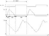
考虑到汽车需要在复杂的路况和环境条件下行驶,作为电动车电源的车载电池需要适应这些复杂的状况,尤其当电动车处于低温环境中时,更需要车载电池具有优异的低温充放电性能和较高的输入输出功率性能。一般而言,在低温条件下会导致车载电池的阻抗增大,极化增强,由此导致车载电池的容量下降。为了保持车载电池在低温条件下的容量,现有的电动车设置有车载电池的加热电路。如图1所示,现有技术中的加热电路F通常与车载电池E构成回路,通过控制能量在车载电池E与加热电路F之间流动使得加热电路F中的阻尼元件发热达到给车载电池E加热的目的,以此提高车载电池E的充放电性能。然而,当电动车在低温环境下需要边行车边加热时,需要通过电动车的负载电容C不断为车辆负载R提供能量,边行车边加热会导致加热电路F与负载电路同时工作,由于加热电路F在工作时会产生负电压,造成负载电容C两端电压波动大,加热电路F也会受到负载电路的影响而导致无法正常工作,如图2的现有技术的电动车行车控制系统中的加热电路F和负载电容C所对应的电压波形时序图所示,其中,VF指的是加热电路F的电压值,VC指的是负载电容C两端的输出电压值。Considering that the car needs to drive under complex road conditions and environmental conditions, the on-board battery as the power source of the electric vehicle needs to adapt to these complex conditions, especially when the electric vehicle is in a low-temperature environment, it is even more necessary for the on-board battery to have excellent low-temperature charge and discharge performance and Higher input and output power performance. Generally speaking, under low temperature conditions, the impedance of the on-board battery will increase, and the polarization will increase, which will lead to a decrease in the capacity of the on-board battery. In order to maintain the capacity of the on-board battery under low temperature conditions, existing electric vehicles are provided with a heating circuit for the on-board battery. As shown in Figure 1, the heating circuit F in the prior art usually forms a circuit with the vehicle battery E, and by controlling the energy flow between the vehicle battery E and the heating circuit F, the damping element in the heating circuit F generates heat to reach the vehicle battery E The purpose of heating is to improve the charging and discharging performance of the vehicle battery E. However, when an electric vehicle needs to be heated while driving in a low-temperature environment, the load capacitor C of the electric vehicle needs to continuously provide energy for the vehicle load R, and heating while driving will cause the heating circuit F to work simultaneously with the load circuit. F will generate a negative voltage when it is working, causing large voltage fluctuations at both ends of the load capacitor C, and the heating circuit F will also be affected by the load circuit and cause it to fail to work normally, as shown in the prior art electric vehicle driving control system in Figure 2 The timing diagram of the voltage waveform corresponding to the heating circuit F and the load capacitance C is shown in the figure, where VF refers to the voltage value of the heating circuit F, and VC refers to the output voltage value at both ends of the load capacitance C.
发明内容Contents of the invention
本发明的目的是针对现有的电动车在低温环境下行车时,由于边行车边加热会导致加热电路和负载电路相互影响,导致加热电路不能正常工作的问题,提供一种能够在电动车边行车边加热时保证加热电路和负载电路互不影响的电动车行车控制系统。The purpose of the present invention is to solve the problem that the heating circuit and the load circuit will interact with each other due to heating while driving when the existing electric vehicle is driving in a low-temperature environment, so that the heating circuit cannot work normally, and to provide a method that can be used on the side of the electric vehicle The electric vehicle driving control system ensures that the heating circuit and the load circuit do not affect each other when heating while driving.
本发明提供的电动车行车控制系统包括加热电路和负载电容C12,所述加热电路用于与车载电池连接构成加热回路,该控制系统还包括开关装置和开关控制模块,该开关装置与所述负载电容C12串联之后与所述加热电路并联,所述开关控制模块与所述开关装置连接,用于在所述加热电路与所述车载电池处于连接状态时控制所述开关装置关断。The electric vehicle driving control system provided by the present invention includes a heating circuit and a load capacitor C12, the heating circuit is used to connect with the vehicle battery to form a heating circuit, the control system also includes a switch device and a switch control module, the switch device is connected to the load The capacitor C12 is connected in parallel with the heating circuit after being connected in series, and the switch control module is connected with the switching device for controlling the switching device to turn off when the heating circuit is connected to the vehicle battery.
优选地,该控制系统还可以包括加热电路控制模块,该加热电路控制模块与所述加热电路连接,用于控制所述加热电路与所述车载电池的连接和断开。Preferably, the control system may further include a heating circuit control module connected to the heating circuit for controlling the connection and disconnection of the heating circuit to the vehicle battery.
优选地,所述加热电路可以包括相互串联的阻尼元件R1、双向开关装置、电流存储元件L1和电荷存储元件C1,所述加热电路控制模块与所述双向开关装置连接,用于通过控制双向开关装置导通和关断来控制所述加热电路与所述车载电池的连接和断开。Preferably, the heating circuit may include a damping element R1, a bidirectional switching device, a current storage element L1 and a charge storage element C1 connected in series, and the heating circuit control module is connected to the bidirectional switching device for controlling the bidirectional switch The device is turned on and off to control the connection and disconnection of the heating circuit to the vehicle battery.
优选地,所述阻尼元件R1可以为所述车载电池内部的寄生电阻,所述电流存储元件L1可以为所述车载电池内部的寄生电感。Preferably, the damping element R1 may be a parasitic resistance inside the vehicle battery, and the current storage element L1 may be a parasitic inductance inside the vehicle battery.
优选地,所述阻尼元件R1可以为电阻,所述电流存储元件L1和电流存储元件L11可以为电感,所述电荷存储元件C1可以为电容。Preferably, the damping element R1 may be a resistor, the current storage element L1 and the current storage element L11 may be an inductor, and the charge storage element C1 may be a capacitor.
优选地,所述开关装置可以为双向开关装置K3。Preferably, the switch device may be a bidirectional switch device K3.
优选地,所述开关装置可以包括双向开关装置K4和双向开关装置K5,所述双向开关装置K4和双向开关装置K5彼此反向串联,所述开关控制模块与所述双向开关装置K4和双向开关装置K5分别连接。Preferably, the switch device may include a bidirectional switch device K4 and a bidirectional switch device K5, the bidirectional switch device K4 and the bidirectional switch device K5 are connected in reverse series with each other, and the switch control module is connected to the bidirectional switch device K4 and the bidirectional switch The device K5 is connected separately.
优选地,所述加热电路还包括能量叠加单元,该能量叠加单元用于在双向开关装置导通再关断后,将加热电路中的能量与车载电池中的能量进行叠加;所述能量叠加单元包括极性反转单元,该极性反转单元用于在双向开关装置导通再关断后,对电荷存储元件C1的电压极性进行反转。Preferably, the heating circuit further includes an energy superimposing unit, which is used to superimpose the energy in the heating circuit and the energy in the vehicle battery after the bidirectional switch device is turned on and then turned off; the energy superimposing unit A polarity inversion unit is included, and the polarity inversion unit is used for inverting the voltage polarity of the charge storage element C1 after the bidirectional switch device is turned on and then turned off.
优选地,所述加热电路还包括能量转移单元,该能量转移单元用于在双向开关装置导通再关断后,将加热电路中的能量转移至储能元件中;所述能量转移单元包括电量回灌单元,该电量回灌单元用于在双向开关装置导通再关断后,将加热电路中的电能转移至所述储能元件中。Preferably, the heating circuit further includes an energy transfer unit, which is used to transfer the energy in the heating circuit to the energy storage element after the bidirectional switch device is turned on and then turned off; the energy transfer unit includes a power The recharging unit is used to transfer the electric energy in the heating circuit to the energy storage element after the bidirectional switch device is turned on and then turned off.
优选地,所述加热电路还包括能量叠加和转移单元;该能量叠加和转移单元用于在双向开关装置导通再关断后,将加热电路中的能量转移至储能元件中,之后将加热电路中的剩余能量与车载电池中的能量进行叠加。Preferably, the heating circuit further includes an energy superposition and transfer unit; the energy superposition and transfer unit is used to transfer the energy in the heating circuit to the energy storage element after the bidirectional switch device is turned on and then turned off, and then the heating The remaining energy in the circuit is superimposed with the energy in the on-board battery.
优选地,所述能量叠加和转移单元包括能量叠加单元和能量转移单元,所述能量转移单元用于在双向开关装置导通再关断后,将加热电路中的能量转移至储能元件中;所述能量叠加单元用于在所述能量转移单元进行能量转移之后,将加热电路中的剩余能量与车载电池中的能量进行叠加;所述能量转移单元包括电量回灌单元,该电量回灌单元用于在双向开关装置导通再关断后,将加热电路中的能量转移至所述储能元件中,所述能量叠加单元包括极性反转单元,该极性反转单元用于在所述电量回灌单元进行能量转移之后,对电荷存储元件C1的电压极性进行反转。Preferably, the energy superposition and transfer unit includes an energy superposition unit and an energy transfer unit, and the energy transfer unit is used to transfer the energy in the heating circuit to the energy storage element after the bidirectional switch device is turned on and then turned off; The energy superposition unit is used to superimpose the remaining energy in the heating circuit and the energy in the vehicle battery after the energy transfer unit performs energy transfer; the energy transfer unit includes a power recharge unit, and the power recharge unit It is used to transfer the energy in the heating circuit to the energy storage element after the bidirectional switch device is turned on and then turned off, and the energy superposition unit includes a polarity inversion unit, which is used to After the power recharging unit performs energy transfer, the voltage polarity of the charge storage element C1 is reversed.
优选地,所述能量叠加和转移单元包括DC-DC模块,所述加热电路控制模块还与所述DC-DC模块连接,用于通过控制DC-DC模块工作来将所述电荷存储元件C1中的能量转移至储能元件中,之后将所述电荷存储元件C1中的剩余能量与电池车载电池中的能量进行叠加。Preferably, the energy superimposition and transfer unit includes a DC-DC module, and the heating circuit control module is also connected to the DC-DC module, and is used to control the operation of the DC-DC module to store energy in the charge storage element C1 The energy of the charge storage element C1 is transferred to the energy storage element, and then the remaining energy in the charge storage element C1 is superimposed with the energy in the battery on-board battery.
优选地,所述极性反转单元包括单刀双掷开关J1和单刀双掷开关J2,所述单刀双掷开关J1和单刀双掷开关J2分别位于所述电荷存储元件C1两端,所述单刀双掷开关J1的入线连接在所述加热电路中,所述单刀双掷开关J1的第一出线连接所述电荷存储元件C1的第一极板,所述单刀双掷开关J1的第二出线连接所述电荷存储元件C1的第二极板,所述单刀双掷开关J2的入线连接在所述加热电路中,所述单刀双掷开关J2的第一出线连接所述电荷存储元件C1的第二极板,所述单刀双掷开关J2的第二出线连接在所述电荷存储元件C1的第一极板,所述加热电路控制模块还与所述单刀双掷开关J1和单刀双掷开关J2分别连接,用于通过改变所述单刀双掷开关J1和单刀双掷开关J2各自的入线和出线的连接关系来对所述电荷存储元件C1的电压极性进行反转。Preferably, the polarity reversing unit includes a single-pole double-throw switch J1 and a single-pole double-throw switch J2, the single-pole double-throw switch J1 and the single-pole double-throw switch J2 are respectively located at both ends of the charge storage element C1, the single-pole The incoming line of the double-throw switch J1 is connected to the heating circuit, the first outgoing line of the single-pole double-throw switch J1 is connected to the first plate of the charge storage element C1, and the second outgoing line of the single-pole double-throw switch J1 The second pole plate of the charge storage element C1 is connected, the input line of the SPDT switch J2 is connected to the heating circuit, and the first output line of the SPDT switch J2 is connected to the charge storage element C1 The second pole plate, the second outgoing line of the SPDT switch J2 is connected to the first pole plate of the charge storage element C1, and the heating circuit control module is also connected with the SPDT switch J1 and the SPDT switch J2 are respectively connected for inverting the voltage polarity of the charge storage element C1 by changing the connection relationship between the input and output lines of the SPDT switch J1 and the SPDT switch J2 respectively.
优选地,所述极性反转单元包括单向半导体元件D3、电流存储元件L2以及开关K9,所述电荷存储元件C1、电流存储元件L2和开关K9顺次串联形成回路,所述单向半导体元件D3串联在所述电荷存储元件C1与电流存储元件L2或所述电流存储元件L2与开关K9之间,所述加热电路控制模块还与所述开关K9连接,用于通过控制开关K9导通来对所述电荷存储元件C1的电压极性进行反转。Preferably, the polarity inversion unit includes a unidirectional semiconductor element D3, a current storage element L2, and a switch K9, the charge storage element C1, the current storage element L2, and the switch K9 are connected in series to form a loop, and the unidirectional semiconductor The element D3 is connected in series between the charge storage element C1 and the current storage element L2 or between the current storage element L2 and the switch K9, and the heating circuit control module is also connected to the switch K9 for conducting by controlling the switch K9 to reverse the voltage polarity of the charge storage element C1.
优选地,所述极性反转单元包括第一DC-DC模块和电荷存储元件C2,所述加热电路控制模块还与所述第一DC-DC模块连接,用于通过控制第一DC-DC模块工作来将所述电荷存储元件C1中的能量转移至所述电荷存储元件C2,再将所述电荷存储元件C2中的能量反向转移回所述电荷存储元件C1,以实现对所述电荷存储元件C1的电压极性的反转。Preferably, the polarity reversing unit includes a first DC-DC module and a charge storage element C2, and the heating circuit control module is also connected to the first DC-DC module for controlling the first DC-DC The module works to transfer the energy in the charge storage element C1 to the charge storage element C2, and then reversely transfer the energy in the charge storage element C2 back to the charge storage element C1 to realize the charge storage Inversion of the voltage polarity of storage element C1.
优选地,所述电量回灌单元包括第二DC-DC模块,所述加热电路控制模块还与所述第二DC-DC模块连接,用于通过控制第二DC-DC模块工作来将电荷存储元件C1中的能量转移到所述车载电池中。Preferably, the power recharging unit includes a second DC-DC module, and the heating circuit control module is also connected to the second DC-DC module, and is used to store electric charge by controlling the operation of the second DC-DC module The energy in element C1 is transferred to the on-board battery.
优选地,该控制系统还包括能量限制电路,该能量限制电路用于限制由加热电路流向车载电池的电流大小。Preferably, the control system further includes an energy limiting circuit, and the energy limiting circuit is used to limit the magnitude of the current flowing from the heating circuit to the vehicle battery.
优选地,所述双向开关装置包括用于实现能量从车载电池流向加热电路的第一单向支路和用于实现能量从加热电路流向车载电池的第二单向支路,所述加热电路控制模块与所述第一单向支路和第二单向支路中的一者或两者分别连接,用以控制所连接的支路的导通和关断。Preferably, the bidirectional switch device includes a first unidirectional branch for realizing energy flowing from the vehicle battery to the heating circuit and a second unidirectional branch for realizing energy flowing from the heating circuit to the vehicle battery, and the heating circuit controls The module is respectively connected to one or both of the first unidirectional branch and the second unidirectional branch, and is used to control the on and off of the connected branch.
优选地,所述能量限制电路包括电流存储元件L111,该电流存储元件L111串联在第二单向支路中。Preferably, the energy limiting circuit includes a current storage element L111 connected in series in the second unidirectional branch.
优选地,所述双向开关装置包括开关K6、单向半导体元件D11以及单向半导体元件D12,开关K6和单向半导体元件D11彼此串联以构成所述第一单向支路,单向半导体元件D12构成所述第二单向支路,所述加热电路控制模块与开关K6连接,用于通过控制开关K6的导通和关断来控制第一单向支路的导通和关断,所述电流存储元件L111与单向半导体元件D12串联。Preferably, the bidirectional switch device includes a switch K6, a unidirectional semiconductor element D11 and a unidirectional semiconductor element D12, the switch K6 and the unidirectional semiconductor element D11 are connected in series to form the first unidirectional branch, and the unidirectional semiconductor element D12 The second unidirectional branch is formed, and the heating circuit control module is connected to the switch K6 for controlling the on and off of the first unidirectional branch by controlling the on and off of the switch K6. The current storage element L111 is connected in series with the unidirectional semiconductor element D12.
优选地,所述双向开关装置还包括位于第二单向支路中的开关K7,该开关K7与单向半导体元件D12串联,所述加热电路控制模块还与开关K7连接,用于通过控制开关K7的导通和关断来控制第二单向支路的导通和关断,所述电流存储元件L111串联在单向半导体元件D12与开关K7之间。Preferably, the bidirectional switch device further includes a switch K7 located in the second unidirectional branch, the switch K7 is connected in series with the unidirectional semiconductor element D12, and the heating circuit control module is also connected to the switch K7 for controlling the switch K7 The turn-on and turn-off of K7 controls the turn-on and turn-off of the second unidirectional branch, and the current storage element L111 is connected in series between the unidirectional semiconductor element D12 and the switch K7.
优选地,该加热电路还包括单向半导体元件D15、单向半导体元件D16、开关K10、开关K11;单向半导体元件D16的阴级连接到开关K7与电荷存储元件L111之间,阳级连接到开关K11的一端,开关K11的另一端连接到车载电池的负级;单向半导体元件D15的阳级连接到单向半导体元件D12与电荷存储元件L111之间,阴级连接到开关K10的一端,开关K10的另一端连接到车载电池的负级;所述加热电路控制模块还与开关K10和开关K11连接,用于控制开关K10和开关K11的导通和关断。Preferably, the heating circuit also includes a unidirectional semiconductor element D15, a unidirectional semiconductor element D16, a switch K10, and a switch K11; the cathode of the unidirectional semiconductor element D16 is connected between the switch K7 and the charge storage element L111, and the anode is connected to One end of the switch K11, the other end of the switch K11 is connected to the negative pole of the vehicle battery; the anode of the one-way semiconductor element D15 is connected between the one-way semiconductor element D12 and the charge storage element L111, and the cathode is connected to one end of the switch K10, The other end of the switch K10 is connected to the negative pole of the vehicle battery; the heating circuit control module is also connected to the switch K10 and the switch K11 for controlling the switch K10 and the switch K11 to be turned on and off.
优选地,所述加热电路控制模块用于:控制开关K6和开关K7导通以使得能量从车载电池流向电荷存储元件C1和从电荷存储元件C1流向车载电池;当电荷存储元件C1两端的电压值达到取值大于车载电池电压的第一预设值时,关断开关K7,导通开关K11;当流经电流存储元件L111的电流为零时关断开关K11,并且导通开关K7和开关K10以使得电荷存储元件C1两端的电压极性反转。Preferably, the heating circuit control module is used to: control switch K6 and switch K7 to conduct so that energy flows from the vehicle battery to the charge storage element C1 and from the charge storage element C1 to the vehicle battery; when the voltage value across the charge storage element C1 When the first preset value greater than the vehicle battery voltage is reached, the switch K7 is turned off and the switch K11 is turned on; when the current flowing through the current storage element L111 is zero, the switch K11 is turned off, and the switch K7 and the switch K10 are turned on In order to reverse the polarity of the voltage across the charge storage element C1.
优选地,所述加热电路控制模块用于:控制开关K6和开关K7导通以使得能量从车载电池流向电荷存储元件C1和从电荷存储元件C1流向车载电池;当电荷存储元件C1两端的电压值达到取值小于等于车载电池电压的第二预设值时,关断开关K7,导通开关K11;当流经电流存储元件L111的电流达到第二电流设置值时,关断开关K11,导通开关K7和开关K10;当流经电流存储元件L111的电流达到第一电流设置值时,关断开关K10以使得电流存储元件L111中的能量流向车载电池;当流经电流存储元件L111的电流为零时导通开关K7和K10以使得电荷存储元件C1两端的电压极性反转。Preferably, the heating circuit control module is used to: control switch K6 and switch K7 to conduct so that energy flows from the vehicle battery to the charge storage element C1 and from the charge storage element C1 to the vehicle battery; when the voltage value across the charge storage element C1 When the value is less than or equal to the second preset value of the vehicle battery voltage, the switch K7 is turned off and the switch K11 is turned on; when the current flowing through the current storage element L111 reaches the second current setting value, the switch K11 is turned off and turned on Switch K7 and switch K10; when the current flowing through the current storage element L111 reaches the first current setting value, switch K10 is turned off so that the energy in the current storage element L111 flows to the vehicle battery; when the current flowing through the current storage element L111 is Switches K7 and K10 are turned on at zero time to reverse the polarity of the voltage across charge storage element C1.
由于本发明提供的电动车行车控制系统中还包括开关装置和开关控制模块,所述开关控制模块用于在所述加热电路与所述车载电池处于连接状态时控制所述开关装置断开,由此,可以在电动车加热时、即加热电路与车载电池连接构成的加热回路导通时,通过开关装置控制车载电池与负载电容的连接断开,停止车载电池向负载电路提供能量,通过控制加热电路与负载电路分时工作来避免其相互影响。Since the electric vehicle driving control system provided by the present invention also includes a switch device and a switch control module, the switch control module is used to control the switch device to be disconnected when the heating circuit is connected to the vehicle battery, by Therefore, when the electric vehicle is heated, that is, when the heating circuit formed by the connection between the heating circuit and the vehicle battery is turned on, the switch device controls the connection between the vehicle battery and the load capacitor to disconnect, stops the vehicle battery from supplying energy to the load circuit, and controls the heating The circuit and the load circuit work in time sharing to avoid their mutual influence.
本发明的其他特征和优点将在随后的具体实施方式部分予以详细说明。Other features and advantages of the present invention will be described in detail in the following detailed description.
附图说明Description of drawings
附图是用来提供对本发明的进一步理解,并且构成说明书的一部分,与下面的具体实施方式一起用于解释本发明,但并不构成对本发明的限制。在附图中:The accompanying drawings are used to provide a further understanding of the present invention, and constitute a part of the description, together with the following specific embodiments, are used to explain the present invention, but do not constitute a limitation to the present invention. In the attached picture:
图1为现有技术中的电动车行车控制系统的结构示意图;Fig. 1 is a schematic structural diagram of an electric vehicle driving control system in the prior art;
图2为与图1中的电动车行车控制系统中的加热电路和负载电容所对应的电压波形时序图;FIG. 2 is a timing diagram of voltage waveforms corresponding to the heating circuit and load capacitance in the electric vehicle driving control system in FIG. 1;
图3为本发明提供的电动车行车控制系统的结构示意图;FIG. 3 is a schematic structural view of the electric vehicle driving control system provided by the present invention;
图4为本发明提供的电动车行车控制系统中加热电路的结构示意图;Fig. 4 is a structural schematic diagram of the heating circuit in the electric vehicle driving control system provided by the present invention;
图5为图4中的开关装置的一种实施方式的示意图;Fig. 5 is a schematic diagram of an embodiment of the switching device in Fig. 4;
图6为图4中的开关装置的一种实施方式的示意图;Fig. 6 is a schematic diagram of an embodiment of the switch device in Fig. 4;
图7为本发明提供的电动车行车控制系统的一种实施方式的结构示意图;Fig. 7 is a structural schematic diagram of an embodiment of the electric vehicle driving control system provided by the present invention;
图8为与图7中的电动车行车控制系统中的加热电路和负载电容对应的波形时序图。FIG. 8 is a timing diagram of waveforms corresponding to the heating circuit and load capacitance in the driving control system of the electric vehicle in FIG. 7 .
图9为本发明提供的电动车行车控制系统的一种优选实施方式的示意图;Fig. 9 is a schematic diagram of a preferred embodiment of the electric vehicle driving control system provided by the present invention;
图10为图9中的能量叠加单元的一种实施方式的示意图;Fig. 10 is a schematic diagram of an embodiment of the energy superposition unit in Fig. 9;
图11为图10中的极性反转单元的一种实施方式的示意图;Fig. 11 is a schematic diagram of an embodiment of the polarity inversion unit in Fig. 10;
图12为图10中的极性反转单元的一种实施方式的示意图;Fig. 12 is a schematic diagram of an embodiment of the polarity inversion unit in Fig. 10;
图13为图10中的极性反转单元的一种实施方式的示意图;Fig. 13 is a schematic diagram of an embodiment of the polarity inversion unit in Fig. 10;
图14为图13中的第一DC-DC模块的一种实施方式的示意图;FIG. 14 is a schematic diagram of an embodiment of the first DC-DC module in FIG. 13;
图15为本发明提供的电动车行车控制系统的一种优选实施方式的示意图;Fig. 15 is a schematic diagram of a preferred embodiment of the electric vehicle driving control system provided by the present invention;
图16为图15中的能量转移单元的一种优选实施方式的示意图;Fig. 16 is a schematic diagram of a preferred embodiment of the energy transfer unit in Fig. 15;
图17为图16中的电量回灌单元的一种实施方式的示意图;Fig. 17 is a schematic diagram of an embodiment of the power recharging unit in Fig. 16;
图18为图17中的第二DC-DC模块的一种实施方式的示意图;Fig. 18 is a schematic diagram of an embodiment of the second DC-DC module in Fig. 17;
图19为本发明提供的电动车行车控制系统的一种优选实施方式的示意图;Fig. 19 is a schematic diagram of a preferred embodiment of the electric vehicle driving control system provided by the present invention;
图20为图19中的能量叠加和转移单元的一种优选实施方式的示意图;Fig. 20 is a schematic diagram of a preferred embodiment of the energy superposition and transfer unit in Fig. 19;
图21为本发明提供的电动车行车控制系统中加热电路的一种实施方式的示意图;Fig. 21 is a schematic diagram of an embodiment of the heating circuit in the electric vehicle driving control system provided by the present invention;
图22为本发明提供的电动车行车控制系统中加热电路的一种优选实施方式的示意图;Fig. 22 is a schematic diagram of a preferred embodiment of the heating circuit in the electric vehicle driving control system provided by the present invention;
图23为本发明提供的电动车行车控制系统中加热电路的一种优选实施方式的示意图。Fig. 23 is a schematic diagram of a preferred embodiment of the heating circuit in the electric vehicle driving control system provided by the present invention.
图24为本发明提供的电动车行车控制系统的一种优选实施方式的结构示意图;以及Fig. 24 is a structural schematic diagram of a preferred embodiment of the electric vehicle driving control system provided by the present invention; and
图25为与图24中的电动车行车控制系统中的加热电路和负载电容对应的波形时序图。FIG. 25 is a timing diagram of waveforms corresponding to the heating circuit and load capacitance in the driving control system of the electric vehicle in FIG. 24 .
具体实施方式Detailed ways
以下结合附图对本发明的具体实施方式进行详细说明。应当理解的是,此处所描述的具体实施方式仅用于说明和解释本发明,并不用于限制本发明。Specific embodiments of the present invention will be described in detail below in conjunction with the accompanying drawings. It should be understood that the specific embodiments described here are only used to illustrate and explain the present invention, and are not intended to limit the present invention.
需要指出的是,除非特别说明,当下文中提及时,术语“加热电路控制模块”为任意能够根据设定的条件或者设定的时刻输出控制指令(例如脉冲波形)从而控制与其连接的加热电路相应地启动或停止的控制器,例如可以为PLC;当下文中提及时,术语“双向开关”指的是可以通过电信号实现通断控制或者根据元器件自身的特性实现通断控制的双向开关,例如金属氧化物半导体型场效应管(MOSFET)或带有反并续流二极管的IGBT;当下文中提及时,术语“电荷存储元件”指任意可以实现电荷存储的装置,例如可以为电容等;当下文中提及时,术语“电流存储元件”指任意可以对电流进行存储的装置,例如可以为电感等;当下文中提及时,术语“正向”指能量从车载电池向加热电路流动的方向,术语“反向”指能量从加热电路向车载电池流动的方向;当下文中提及时,术语“车载电池”包括一次电池(例如干电池、碱性电池等)和二次电池(例如锂离子电池、镍镉电池、镍氢电池或铅酸电池等);当下文中提及时,术语“阻尼元件”指任意通过对电流的流动起阻碍作用以实现能量消耗的装置,例如可以为电阻等;当下文中提及时,术语“加热回路”指的是车载电池与加热电路组成的回路。It should be pointed out that, unless otherwise specified, when mentioned below, the term "heating circuit control module" refers to any module capable of outputting control commands (such as pulse waveforms) according to set conditions or set moments to control the corresponding heating circuit connected to it. A controller that starts or stops automatically, such as a PLC; when mentioned below, the term "bidirectional switch" refers to a bidirectional switch that can realize on-off control through electrical signals or realize on-off control according to the characteristics of the components themselves, such as Metal Oxide Semiconductor Field Effect Transistor (MOSFET) or IGBT with anti-parallel freewheeling diode; when mentioned below, the term "charge storage element" refers to any device that can realize charge storage, such as a capacitor; when mentioned below When mentioned, the term "current storage element" refers to any device that can store current, such as an inductor; when mentioned below, the term "forward" refers to the direction in which energy flows from the vehicle battery to the heating circuit, and the term "reverse" "to" refers to the direction in which energy flows from the heating circuit to the on-board battery; when referred to below, the term "on-board battery" includes primary batteries (such as dry batteries, alkaline batteries, etc.) and secondary batteries (such as lithium-ion batteries, nickel-cadmium batteries, Ni-MH battery or lead-acid battery, etc.); when mentioned hereinafter, the term "damping element" refers to any device that hinders the flow of current to achieve energy consumption, such as a resistor, etc.; when mentioned hereinafter, the term "damping element" "Heating circuit" refers to the circuit composed of the on-board battery and the heating circuit.
这里还需要特别说明的是,考虑到不同类型的车载电池的不同特性,在本发明中,“车载电池”可以指不包含内部寄生电阻和寄生电感、或者内部寄生电阻的阻值和寄生电感的电感值较小的理想电池,也可以指包含有内部寄生电阻和寄生电感的电池包;因此,本领域技术人员应当理解的是,当“车载电池”为不包含内部寄生电阻和寄生电感、或者内部寄生电阻的阻值和寄生电感的电感值较小的理想电池时,阻尼元件R1指的是车载电池外部的阻尼元件,电流存储元件L1指的是车载电池外部的电流存储元件;当“车载电池”为包含有内部寄生电阻和寄生电感的电池包时,阻尼元件R1既可以指电池包外部的阻尼元件,也可以指电池包内部的寄生电阻,同样地,电流存储元件L1既可以指电池包外部的电流存储元件,也可以指电池包内部的寄生电感。What needs to be specially explained here is that, considering the different characteristics of different types of on-board batteries, in the present invention, "on-board battery" may refer to the An ideal battery with a small inductance value can also refer to a battery pack containing internal parasitic resistance and parasitic inductance; therefore, those skilled in the art should understand that when the "vehicle battery" does not contain internal parasitic resistance and parasitic inductance, or For an ideal battery with a small resistance value of the internal parasitic resistance and a small inductance value of the parasitic inductance, the damping element R1 refers to the damping element outside the vehicle battery, and the current storage element L1 refers to the current storage element outside the vehicle battery; when "vehicle When "battery" is a battery pack containing internal parasitic resistance and parasitic inductance, the damping element R1 can refer to either the damping element outside the battery pack or the parasitic resistance inside the battery pack. Similarly, the current storage element L1 can refer to the battery The current storage element outside the pack can also refer to the parasitic inductance inside the pack.
为了实现电动车在低温环境中边行车边加热,本发明提供了一种电动车行车控制系统,如图3所示,该控制系统包括加热电路11和负载电容C12,所述加热电路11用于与车载电池5连接构成加热回路,所述负载电容C12用于为车辆负载6提供能量,该控制系统还包括开关装置20和开关控制模块200,该开关装置20与所述负载电容C12串联之后与所述加热电路11并联,所述开关控制模块200与所述开关装置20连接,用于在所述加热电路11与所述车载电池5处于连接状态时控制所述开关装置20关断。In order to realize heating of electric vehicles while driving in a low-temperature environment, the present invention provides a driving control system for electric vehicles, as shown in Figure 3, the control system includes a
为了保证车载电池的使用寿命,可以在低温情况下控制加热电路11与车载电路连接,通过加热电路11对车载电池进行加热。当达到加热条件时,对车载电池进行加热,当达到停止加热条件时,断开加热电路11与车载电池的连接。In order to ensure the service life of the on-board battery, the
如图4所示,本发明提供的电动车行车控制系统还包括加热电路控制模块100,该加热电路控制模块100与所述加热电路11连接,用于控制所述加热电路11与所述车载电池5的连接和断开。As shown in Figure 4, the electric vehicle driving control system provided by the present invention also includes a heating
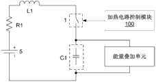
所述加热电路11包括相互串联的阻尼元件R1、双向开关装置1、电流存储元件L1和电荷存储元件C1,所述加热电路控制模块100与所述双向开关装置1连接,用于通过控制双向开关装置1导通和关断来控制所述加热电路11与所述车载电池5的连接和断开。The
由此,当达到加热条件时,加热电路控制模块100控制双向开关装置1导通,车载电池5与加热电路11连接构成回路,车载电池5可以通过回路放电,即对电荷存储元件C1进行充电,当回路中的电流经过电流峰值后正向为零时,电荷存储元件C1开始通过回路放电,即是对车载电池5充电;在车载电池5的充放电过程中,回路中的电流正向、反向均能流过阻尼元件R1,通过阻尼元件R1的发热可以达到给车载电池5加热的目的。当达到停止加热条件时,加热电路控制模块100可以控制双向开关装置1关断,加热电路11停止工作。Thus, when the heating condition is reached, the heating
根据本发明的技术方案,本发明提供的电动车行车控制系统中还包括开关装置20和开关控制模块200,该开关装置20与所述负载电容C12串联之后与所述加热电路11并联,所述开关控制模块200与所述开关装置20连接,用于在所述加热电路11与所述车载电池5处于连接状态时控制所述开关装置20关断。According to the technical solution of the present invention, the electric vehicle driving control system provided by the present invention further includes a
由此,在电动车加热时、即加热电路11与车载电池5连接构成的加热回路导通时,可以通过开关装置20控制车载电池5与负载电容C12的连接断开,停止车载电池5向负载电容C12提供能量,通过控制加热电路11与负载电路分时工作来避免其相互影响。Thus, when the electric vehicle is heated, that is, when the heating circuit formed by the connection of the
根据一种实施方式,所述开关装置20为双向开关K3,如图5所示,由开关控制模块200控制双向开关K3关断来控制车载电池5与负载电容C12的连接断开。According to one embodiment, the
根据另一种实施方式,如图6所示,所述开关装置20包括双向开关K4和双向开关K5,所述双向开关K4和双向开关K5彼此反向串联,所述开关控制模块200与所述双向开关K4和双向开关K5分别连接,用于通过控制双向开关K4和双向开关K5的关断来控制车载电池5与负载电容C12的连接断开。在该实施方式中,所述开关控制模块200可以为一个单独的控制器,通过对其内部程序的设置,可以实现对不同的外接开关的通断控制,所述开关控制模块200也可以为多个控制器,例如针对每一个外接开关设置对应的开关控制模块200,所述多个开关控制模块200也可以集成为一体,本发明不对开关控制模块200的实现形式作出任何限定。According to another implementation, as shown in FIG. 6 , the
优选情况下,所述加热电路控制模块100与所述开关控制模块200集成在一起。Preferably, the heating
下面结合图7和图8对本发明提供的电动车行车控制系统的工作方式进行简单介绍。需要注意的是,虽然本发明的特征和元素参考图7和图8以特定的结合进行了描述,但每个特征或元素可以在没有其它特征和元素的情况下单独使用,或在与或不与其它特征和元素结合的各种情况下使用。本发明提供的电动车行车控制系统并不限于图7和图8所示的实现方式。The working mode of the electric vehicle driving control system provided by the present invention will be briefly introduced below with reference to FIG. 7 and FIG. 8 . It should be noted that although the features and elements of the present invention are described in particular combinations with reference to FIGS. Used in various contexts in combination with other features and elements. The electric vehicle driving control system provided by the present invention is not limited to the implementations shown in FIG. 7 and FIG. 8 .
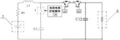
在图7中所示的电动车行车控制系统中,加热电路11包括相互串联的阻尼元件R1、双向开关装置1、电流存储元件L1和电荷存储元件C1,加热电路11与车载电池5连接构成回路,车辆负载6并联在负载电容C12两端,用于通过负载电容C12提供的能量工作,加热电路控制模块100与双向开关装置1连接,用于通过控制双向开关装置1导通和关断来控制所述加热电路11与所述车载电池5的连接和断开,所述开关装置20由双向开关K4和双向开关K5反向串联构成,开关控制模块200与所述双向开关K4和双向开关K5分别连接,用于通过控制双向开关K4和双向开关K5的关断来控制车载电池5与负载电容C12的连接断开。In the electric vehicle driving control system shown in Figure 7, the
图8为与图7中的加热电路11和负载电容C12对应的波形时序图,其中,VC1为加热电路11中的电荷存储元件C1两端的电压值,VC12为负载电容C12两端的电压值。图7中的电动车行车控制系统边行车边加热的工作过程如下:Fig. 8 is a waveform timing diagram corresponding to the
a)在电动车行车过程中,当需要对车载电池5进行加热时,加热电路控制模块100控制双向开关装置1导通,加热电路11与车载电池5连接构成加热回路,车载电池5通过加热电路11放电,即对加热电路11中的电荷存储元件C1进行充电,同时,开关控制模块200控制双向开关装置K4和双向开关装置K5关断,断开车载电池5与负载电容C12的连接,此时电动车在行车过程中,负载电容C12中剩余的能量可以供车辆负载6短暂工作,如图8中所示的t1时间段;a) During the driving process of the electric vehicle, when the on-
b)当加热回路中的电流经过电流峰值后正向为零时,加热电路11中的电荷存储元件C1开始通过加热回路向车载电池5充电,当加热电路11中的电荷存储元件C1放电达到最低电压值时,所述加热电路控制模块100可以控制双向开关装置1关断,断开所述加热电路11与所述车载电池5的连接,电荷存储元件C1保持最低电压值,如图8中所示的t2时间段;b) When the current in the heating circuit passes through the current peak value and becomes zero in the positive direction, the charge storage element C1 in the
c)当负载电容C12中的能量不足以供车辆负载6工作时,可以通过开关控制模块200控制双向开关K4和双向开关K5导通,控制车载电池5与负载电容C12连接,可以通过车载电池5对负载电容C12充电,车辆负载6可以通过负载电容C12提供的能量工作,如图8中所示的t3时间段。c) When the energy in the load capacitor C12 is not enough for the
本发明提供的电动车行车控制系统中包括开关装置20和开关控制模块200,在电动车加热时、即加热电路11与车载电池5连接构成的加热回路导通时,可以通过开关装置20控制车载电池5与负载电容C12的连接断开,停止车载电池5向负载电容C12提供能量,通过控制加热电路11与负载电路分时工作来避免其相互影响。The electric vehicle driving control system provided by the present invention includes a
在上述加热过程中,当电流从加热电路11流回车载电池5时,电荷存储元件C1中的能量不会完全流回车载电池5,而是会有一些能量余留在电荷存储元件C1中,最终使得电荷存储元件C1电压接近或等于车载电池5的电压,从而使得从车载电池5向电荷存储元件C1的能量流动不能进行,不利于加热电路11的循环工作。During the above heating process, when the current flows from the
因此,本发明优选实施方式中还增加了将电荷存储元件C1内的能量与车载电池5的能量进行叠加、将电荷存储元件C1内的能量转移到其他储能元件等功能的附加单元。在达到一定时刻时,关断双向开关装置1,对电荷存储元件C1中的能量进行叠加、转移等操作。Therefore, in the preferred embodiment of the present invention, an additional unit with functions such as superimposing the energy in the charge storage element C1 and the energy of the
根据本发明的一种优选实施方式,如图9所示,本发明提供的控制系统中,加热电路11可以包括能量叠加单元,该能量叠加单元与所述电流存储元件L1和电荷存储元件C1形成的通路连接,用于在双向开关装置1导通再关断后,将加热电路11中的能量与车载电池5中的能量进行叠加。所述能量叠加单元使得在双向开关装置1再次导通时,车载电池5能够将叠加后的能量充入电荷存储元件C1,由此提高加热电路11的工作效率。According to a preferred embodiment of the present invention, as shown in FIG. 9 , in the control system provided by the present invention, the
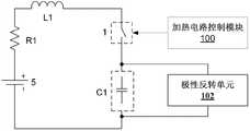
根据本发明的一种实施方式,如图10所示,所述能量叠加单元包括极性反转单元102,该极性反转单元102与所述电流存储元件L1和电荷存储元件C1形成的通路连接,用于在双向开关装置1导通再关断后,对电荷存储元件C1的电压极性进行反转,由于极性反转后的电荷存储元件C1的电压极性与车载电池5的电压极性形成串联相加关系,当双向开关装置1再次导通时,电荷存储元件C1中的能量可以与车载电池5中的能量进行叠加。According to an embodiment of the present invention, as shown in FIG. 10 , the energy superposition unit includes a
作为极性反转单元102的一种实施方式,如图11所示,所述极性反转单元102包括单刀双掷开关J1和单刀双掷开关J2,所述单刀双掷开关J1和单刀双掷开关J2分别位于所述电荷存储元件C1两端,所述单刀双掷开关J1的入线连接在所述加热电路11中,所述单刀双掷开关J1的第一出线连接所述电荷存储元件C1的第一极板,所述单刀双掷开关J1的第二出线连接所述电荷存储元件C1的第二极板,所述单刀双掷开关J2的入线连接在所述加热电路11中,所述单刀双掷开关J2的第一出线连接所述电荷存储元件C1的第二极板,所述单刀双掷开关J2的第二出线连接在所述电荷存储元件C1的第一极板,所述加热电路控制模块100还与所述单刀双掷开关J1和单刀双掷开关J2分别连接,用于通过改变所述单刀双掷开关J1和单刀双掷开关J2各自的入线和出线的连接关系来对所述电荷存储元件C1的电压极性进行反转。As an implementation of the
根据上述实施方式,可以预先对单刀双掷开关J1和单刀双掷开关J2各自的入线和出线的连接关系进行设置,使得当双向开关装置1导通时,所述单刀双掷开关J1的入线与其第一出线连接,而所述单刀双掷开关J2的入线与其第一出线连接,当双向开关装置1关断时,通过加热电路控制模块100控制单刀双掷开关J1的入线切换到与其第二出线连接,而所述单刀双掷开关J2的入线切换到与其第二出线连接,由此实现电荷存储元件C1电压极性反转的目的。According to the above embodiment, the connection relationship between the incoming and outgoing lines of the SPDT switch J1 and the SPDT switch J2 can be set in advance, so that when the
作为极性反转单元102的另一种实施方式,如图12所示,所述极性反转单元102包括单向半导体元件D3、电流存储元件L2以及开关K9,所述电荷存储元件C1、电流存储元件L2和开关K9顺次串联形成回路,所述单向半导体元件D3和串联在所述电荷存储元件C1与电流存储元件L2或所述电流存储元件L2与开关K9之间,所述加热电路控制模块100还与所述开关K9连接,用于通过控制开关K9导通来对所述电荷存储元件C1的电压极性进行反转。As another implementation of the
根据上述实施方式,当双向开关装置1关断时,可以通过加热电路控制模块100控制开关K9导通,由此,电荷存储元件C1与单向半导体元件D3、电流存储元件L2以及开关K9形成LC振荡回路,电荷存储元件C1通过电流存储元件L2放电,振荡回路上的电流流经正半周期后,流经电流存储元件L2的电流为零时达到电荷存储元件C1电压极性反转的目的。According to the above embodiment, when the
作为极性反转单元102的又一种实施方式,如图13所示,所述极性反转单元102包括第一DC-DC模块2和电荷存储元件C2,该第一DC-DC模块2与所述电荷存储元件C1和电荷存储元件C2分别连接,所述加热电路控制模块100还与所述第一DC-DC模块2连接,用于通过控制第一DC-DC模块2工作来将所述电荷存储元件C1中的能量转移至所述电荷存储元件C2,再将所述电荷存储元件C2中的能量反向转移回所述电荷存储元件C1,以实现对所述电荷存储元件C1的电压极性的反转。As yet another embodiment of the
所述第一DC-DC模块2是本领域中常用的用于实现电压极性反转的直流变直流转换电路,本发明不对第一DC-DC模块2的具体电路结构作任何限制,只要能够实现对电荷存储元件C1的电压极性反转即可,本领域技术人员可以根据实际操作的需要对其电路中的元件进行增加、替换或删减。The first DC-
图14为本发明提供的第一DC-DC模块2的一种实施方式,如图14所示,所述第一DC-DC模块2包括:双向开关Q1、双向开关Q2、双向开关Q3、双向开关Q4、第一变压器T1、单向半导体元件D4、单向半导体元件D5、电流存储元件L3、双向开关Q5、双向开关Q6、第二变压器T2、单向半导体元件D6、单向半导体元件D7、以及单向半导体元件D8。Fig. 14 is an embodiment of the first DC-
在该实施方式中,双向开关Q1、双向开关Q2、双向开关Q3和双向开关Q4均为MOSFET,双向开关Q5和双向开关Q6为IGBT。In this embodiment, the bidirectional switch Q1 , the bidirectional switch Q2 , the bidirectional switch Q3 and the bidirectional switch Q4 are all MOSFETs, and the bidirectional switch Q5 and the bidirectional switch Q6 are IGBTs.
其中,所述第一变压器T1的1脚、4脚、5脚为同名端,第二变压器T2的2脚与3脚为同名端。Wherein, pins 1, 4, and 5 of the first transformer T1 are terminals with the same name, and pins 2 and 3 of the second transformer T2 are terminals with the same name.
其中,单向半导体元件D7的阳极与电容C1的a端连接,单向半导体元件D7的阴极与双向开关Q1和双向开关Q2的漏极连接,双向开关Q1的源极与双向开关Q3的漏极连接,双向开关Q2的源极与双向开关Q4的漏极连接,双向开关Q3、双向开关Q4的源极与电容C1的b端连接,由此构成全桥电路,此时电容C1的电压极性为a端为正,b端为负。Wherein, the anode of the unidirectional semiconductor element D7 is connected to the terminal a of the capacitor C1, the cathode of the unidirectional semiconductor element D7 is connected to the drains of the bidirectional switch Q1 and the bidirectional switch Q2, and the source of the bidirectional switch Q1 is connected to the drain of the bidirectional switch Q3 connection, the source of the bidirectional switch Q2 is connected to the drain of the bidirectional switch Q4, the sources of the bidirectional switch Q3 and Q4 are connected to the b terminal of the capacitor C1, thus forming a full bridge circuit, and the voltage polarity of the capacitor C1 at this time Terminal a is positive and terminal b is negative.
在该全桥电路中,双向开关Q1、双向开关Q2为上桥臂,双向开关Q3、双向开关Q4为下桥臂,该全桥电路通过第一变压器T1与所述电荷存储元件C2相连;第一变压器T1的1脚与第一节点N1连接、2脚与第二节点N2连接,3脚和5脚分别连接至单向半导体元件D4和单向半导体元件D5的阳极;单向半导体元件D4和单向半导体元件D5的阴极与电流存储元件L3的一端连接,电流存储元件L3的另一端与电荷存储元件C2的d端连接;变压器T1的4脚与电荷存储元件C2的c端连接,单向半导体元件D8的阳极与电荷存储元件C2的d端连接,单向半导体元件D8的阴极与电荷存储元件C1的b端连接,此时电荷存储元件C2的电压极性为c端为负,d端为正。In the full bridge circuit, the bidirectional switch Q1 and the bidirectional switch Q2 are the upper bridge arms, the bidirectional switch Q3 and the bidirectional switch Q4 are the lower bridge arms, and the full bridge circuit is connected to the charge storage element C2 through the first transformer T1; the
其中,电荷存储元件C2的c端连接双向开关Q5的发射极,双向开关Q5的集电极与变压器T2的2脚连接,变压器T2的1脚与电荷存储元件C1的a端连接,变压器T2的4脚与电荷存储元件C1的a端连接,变压器T2的3脚连接单向半导体元件D6的阳极,单向半导体元件D6的阴极与双向开关Q6的集电极连接,双向开关Q6的发射极与电荷存储元件C2的b端连接。Wherein, the c terminal of the charge storage element C2 is connected to the emitter of the bidirectional switch Q5, the collector of the bidirectional switch Q5 is connected to the 2 pin of the transformer T2, the 1 pin of the transformer T2 is connected to the a terminal of the charge storage element C1, and the 4 pin of the transformer T2 The pin is connected to the a terminal of the charge storage element C1, the 3 pin of the transformer T2 is connected to the anode of the unidirectional semiconductor element D6, the cathode of the unidirectional semiconductor element D6 is connected to the collector of the bidirectional switch Q6, and the emitter of the bidirectional switch Q6 is connected to the charge storage Terminal b of element C2 is connected.
其中,双向开关Q1、双向开关Q2、双向开关Q3、双向开关Q4、双向开关Q5和双向开关Q6分别通过所述加热电路控制模块100的控制来实现导通和关断。Wherein, the bidirectional switch Q1 , bidirectional switch Q2 , bidirectional switch Q3 , bidirectional switch Q4 , bidirectional switch Q5 and bidirectional switch Q6 are respectively controlled by the heating
下面对所述第一DC-DC模块2的工作过程进行描述:The working process of the first DC-
1、在双向开关装置1关断后,所述加热电路控制模块100控制双向开关Q5、双向开关Q6关断,控制双向开关Q1和双向开关Q4同时导通以构成A相,控制双向开关Q2、双向开关Q3同时导通以构成B相,通过控制所述A相、B相交替导通以构成全桥电路进行工作;1. After the
2、当所述全桥电路工作时,电荷存储元件C1上的能量通过第一变压器T1、单向半导体元件D4、单向半导体元件D5、以及电流存储元件L3转移到电荷存储元件C2上,此时电荷存储元件C2的电压极性为c端为负,d端为正。2. When the full bridge circuit is working, the energy on the charge storage element C1 is transferred to the charge storage element C2 through the first transformer T1, the unidirectional semiconductor element D4, the unidirectional semiconductor element D5, and the current storage element L3. At this time, the voltage polarity of the charge storage element C2 is negative at the c terminal and positive at the d terminal.
3、所述加热电路控制模块100控制双向开关Q5导通,电荷存储元件C1通过第二变压器T2和单向半导体元件D8与电荷存储元件C2构成通路,由此,电荷存储元件C2上的能量向电荷存储元件C1反向转移,其中,部分能量将储存在第二变压器T2上;此时,所述加热电路控制模块100控制双向开关Q5关断、双向开关Q6闭合,通过第二变压器T2和单向半导体元件D6将储存在第二变压器T2上的能量转移至电荷存储元件C1,以实现对电荷存储元件C1进行反向充电,此时电荷存储元件C1的电压极性反转为a端为负,b端为正,由此达到了将电荷存储元件C1的电压极性反向的目的。3. The heating
本领域技术人员应当理解,对电荷存储元件C1的电压极性进行反转的实现方式并不局限于上述几种特定结构,本领域技术人员可以采用其他结构来实现对电荷存储元件C1的电压极性进行反转,例如电荷泵等。Those skilled in the art should understand that the implementation of inverting the voltage polarity of the charge storage element C1 is not limited to the above-mentioned specific structures, and those skilled in the art can adopt other structures to realize the voltage polarity reversal of the charge storage element C1. Reversal, such as charge pumps, etc.
为了对加热电路11中的能量进行回收利用,根据本发明的一种优选实施方式,如图15所示,本发明提供的控制系统中,加热电路11可以包括能量转移单元,所述能量转移单元与所述电流存储元件L1和电荷存储元件C1形成的通路连接,用于在双向开关装置1导通再关断后,将加热电路11中的能量转移至储能元件中。所述能量转移单元目的在于对存储电路中的能量进行回收利用。所述储能元件可以是外接电容、低温电池或者电网以及其他用电设备。In order to recycle the energy in the
优选情况下,所述储能元件是本发明提供的车载电池5,所述能量转移单元包括电量回灌单元103,该电量回灌单元103与所述电流存储元件L1和电荷存储元件C1形成的通路连接,用于在双向开关装置1导通再关断后,将加热电路11中的能量转移至所述车载电池5中,如图16所示。Preferably, the energy storage element is the on-
根据本发明的技术方案,在双向开关装置1关断后,通过能量转移单元将加热电路11中的能量转移到车载电池5中,能够在双向开关装置1再次导通后对被转移的能量进行循环利用,提高了加热电路11的工作效率。According to the technical solution of the present invention, after the
作为电量回灌单元103的一种实施方式,如图17所示,所述电量回灌单元103包括第二DC-DC模块3,该第二DC-DC模块3与所述电荷存储元件C1和所述车载电池5分别连接,所述加热电路控制模块100还与所述第二DC-DC模块3连接,用于通过控制第二DC-DC模块3工作来将电荷存储元件C1中的能量转移到所述车载电池5中。As an implementation manner of the power recharging unit 103, as shown in FIG. The on-
所述第二DC-DC模块3是本领域中常用的用于实现能量转移的直流变直流转换电路,本发明不对第二DC-DC模块3的具体电路结构作任何限制,只要能够实现对电荷存储元件C1的能量进行转移即可,本领域技术人员可以根据实际操作的需要对其电路中的元件进行增加、替换或删减。The second DC-
图18为本发明提供的第二DC-DC模块3的一种实施方式,如图18所示,所述第二DC-DC模块3包括:双向开关S1、双向开关S2、双向开关S3、双向开关S4、第三变压器T3、电流存储元件L4、以及四个单向半导体元件。在该实施方式中,所述双向开关S1、双向开关S2、双向开关S3、双向开关S4均为MOSFET。Fig. 18 is an embodiment of the second DC-
其中,所述第三变压器T3的1脚和3脚为同名端,所述四个单向半导体元件中的两个单向半导体元件负极相接成组,接点通过电流存储元件L4与车载电池5的正端连接,另两个单向半导体元件正极相接成组,接点与车载电池5的负端连接,且组与组之间的对接点分别与第三变压器T3的3脚和4脚连接,由此构成桥式整流电路。Wherein,
其中,双向开关S1的源极与双向开关S3的漏极连接,双向开关S2的源极与双向开关S4的漏极连接,双向开关S1、双向开关S2的漏极与电荷存储元件C1的正端连接,双向开关S3、双向开关S4的源极与电荷存储元件C1的负端连接,由此构成全桥电路。Wherein, the source of the bidirectional switch S1 is connected to the drain of the bidirectional switch S3, the source of the bidirectional switch S2 is connected to the drain of the bidirectional switch S4, and the drains of the bidirectional switch S1 and the bidirectional switch S2 are connected to the positive terminal of the charge storage element C1 The sources of the bidirectional switch S3 and the bidirectional switch S4 are connected to the negative terminal of the charge storage element C1, thereby forming a full bridge circuit.
在该全桥电路中,双向开关S1、双向开关S2为上桥臂,双向开关S3、双向开关S4为下桥臂,第三变压器T3的1脚与双向开关S1和双向开关S3之间的节点连接、2脚与双向开关S2和双向开关S4之间的节点连接。In this full bridge circuit, the bidirectional switch S1 and the bidirectional switch S2 are the upper bridge arms, the bidirectional switch S3 and the bidirectional switch S4 are the lower bridge arms, and the node between
其中,双向开关S1、双向开关S2、双向开关S3和双向开关S4分别通过所述加热电路控制模块100的控制来实现导通和关断。Wherein, the bidirectional switch S1 , the bidirectional switch S2 , the bidirectional switch S3 and the bidirectional switch S4 are respectively turned on and off under the control of the heating
下面对所述第二DC-DC模块3的工作过程进行描述:The working process of the second DC-
1、在双向开关装置1关断后,所述加热电路控制模块100控制双向开关S1和双向开关S4同时导通以构成A相,控制双向开关S2、双向开关S3同时导通以构成B相,通过控制所述A相、B相交替导通以构成全桥电路进行工作;1. After the
2、当所述全桥电路工作时,电荷存储元件C1上的能量通过第三变压器T3和整流电路转移到车载电池5上,所述整流电路将输入的交流电转化为直流电输出至车载电池5,达到电量回灌的目的。2. When the full bridge circuit is working, the energy on the charge storage element C1 is transferred to the
本领域技术人员应当理解,将加热电路11中的能量转移到储能元件中的实现方式并不局限于上述特定结构,本领域技术人员可以采用其他结构来实现对加热电路11中的能量的转移,例如电荷泵、变压器等。Those skilled in the art should understand that the implementation of transferring the energy in the
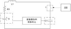
为了使本发明提供的加热电路11在提高工作效率的同时能够对加热电路11中的能量进行回收利用,根据本发明的一种优选实施方式,如图19所示,本发明提供的控制系统中,加热电路11可以包括能量叠加和转移单元,该能量叠加和转移单元与所述电流存储元件L1和电荷存储元件C1形成的通路连接,用于在双向开关装置1导通再关断后,将加热电路11中的能量转移至储能元件中,之后将加热电路11中的剩余能量与车载电池5中的能量进行叠加。所述能量叠加和转移单元既能够提高加热电路11的工作效率,又能够对加热电路11中的能量进行回收利用。In order to enable the
将加热电路11中的剩余能量与车载电池5中的能量进行叠加可以通过将电荷存储元件C1的电压极性进行反转来实现,电荷存储元件C1的电压极性进行反转后其极性与车载电池5的电压极性形成串联相加关系,由此,当下一次导通双向开关装置1时,车载电池5中的能量能够与电荷存储元件C1中的能量进行叠加。The superimposition of the remaining energy in the
因此,根据一种实施方式,如图20所示,所述能量叠加和转移单元包括DC-DC模块4,该DC-DC模块4与所述电荷存储元件C1和所述车载电池5分别连接,所述加热电路控制模块100还与所述DC-DC模块4连接,用于通过控制DC-DC模块4工作来将所述电荷存储元件C1中的能量转移至储能元件中,之后将所述电荷存储元件C1中的剩余能量与车载电池5中的能量进行叠加。Therefore, according to an implementation manner, as shown in FIG. 20 , the energy superposition and transfer unit includes a DC-
所述DC-DC模块4是本领域中常用的用于实现能量转移和电压极性反转的直流变直流转换电路,本发明不对DC-DC模块4的具体电路结构作任何限制,只要能够实现对电荷存储元件C1的能量转移和电压极性反转即可,本领域技术人员可以根据实际操作的需要对其电路中的元件进行增加、替换或删减。The DC-
作为DC-DC模块4的一种实施方式,如图20所示,该DC-DC模块4包括:双向开关S1、双向开关S2、双向开关S3、双向开关S4、双向开关S5、双向开关S6、第四变压器T4、单向半导体元件D13、单向半导体元件D14、电流存储元件L4、以及四个单向半导体元件。在该实施方式中,所述双向开关S1、双向开关S2、双向开关S3、双向开关S4均为MOSFET,双向开关S5和双向开关S6为IGBT。As an implementation of the DC-
其中,第四变压器T4的1脚和3脚为同名端,所述四个单向半导体元件中的两个单向半导体元件负极相接成组,接点通过电流存储元件L4与车载电池5的正端连接,另两个单向半导体元件正极相接成组,接点与车载电池5的负端连接,且组与组之间的对接点分别通过双向开关S5和双向开关S6与第三变压器T3的3脚和4脚连接,由此构成桥式整流电路。Wherein,
其中,双向开关S1的源极与双向开关S3的漏极连接,双向开关S2的源极与双向开关S4的漏极连接,双向开关S1、双向开关S2的漏极通过单向半导体元件D13与电荷存储元件C1的正端连接,双向开关S3、双向开关S4的源极通过单向半导体元件D14与电荷存储元件C1的负端连接,由此构成全桥电路。Wherein, the source of the bidirectional switch S1 is connected to the drain of the bidirectional switch S3, the source of the bidirectional switch S2 is connected to the drain of the bidirectional switch S4, and the drains of the bidirectional switch S1 and the bidirectional switch S2 are connected to the electric charge via the unidirectional semiconductor element D13. The positive end of the storage element C1 is connected, and the sources of the bidirectional switches S3 and S4 are connected to the negative end of the charge storage element C1 through the unidirectional semiconductor element D14, thereby forming a full bridge circuit.
在该全桥电路中,双向开关S1、双向开关S2为上桥臂,双向开关S3、双向开关S4为下桥臂,第四变压器T4的1脚与双向开关S1和双向开关S3之间的节点连接、2脚与双向开关S2和双向开关S4之间的节点连接。In this full bridge circuit, the bidirectional switch S1 and the bidirectional switch S2 are the upper bridge arms, the bidirectional switch S3 and the bidirectional switch S4 are the lower bridge arms, and the node between
其中,双向开关S1、双向开关S2、双向开关S3和双向开关S4、双向开关S5和双向开关S6分别通过所述加热电路控制模块100的控制来实现导通和关断。Wherein, the bidirectional switch S1 , the bidirectional switch S2 , the bidirectional switch S3 , the bidirectional switch S4 , the bidirectional switch S5 and the bidirectional switch S6 are respectively turned on and off under the control of the heating
下面对所述DC-DC模块4的工作过程进行描述:The working process of the DC-
1、在双向开关装置1关断后,当需要对电荷存储元件C1执行电量回灌以实现能量转移时,所述加热电路控制模块100控制双向开关S5和S6导通,控制双向开关S1和双向开关S4同时导通以构成A相,控制双向开关S2、双向开关S3同时导通以构成B相,通过控制所述A相、B相交替导通以构成全桥电路进行工作;1. After the
2、当所述全桥电路工作时,电荷存储元件C1上的能量通过第四变压器T4和整流电路转移到车载电池5上,所述整流电路将输入的交流电转化为直流电输出至车载电池5,达到电量回灌的目的;2. When the full bridge circuit is working, the energy on the charge storage element C1 is transferred to the
3、当需要对电荷存储元件C1进行极性反转以实现能量叠加时,所述加热电路控制模块100控制双向开关S5和双向开关S6关断,控制双向开关S1和双向开关S4或者双向开关S2和双向开关S3两组中的任意一组导通;此时,电荷存储元件C1中的能量通过其正端、双向开关S1、第四变压器T4的原边、双向开关S4反向回到其负端,或者通过其正端、双向开关S2、第四变压器T4的原边、双向开关S3反向回到其负端,利用T4的原边励磁电感,达到对电荷存储元件C1进行电压极性反转的目的。3. When it is necessary to reverse the polarity of the charge storage element C1 to achieve energy superposition, the heating
根据另一种实施方式,所述能量叠加和转移单元可以包括能量叠加单元和能量转移单元,所述能量转移单元与所述电流存储元件L1和电荷存储元件C1形成的通路连接,用于在双向开关装置1导通再关断后,将加热电路11中的能量转移至储能元件中,所述能量叠加单元与所述电流存储元件L1和电荷存储元件C1形成的通路连接,用于在所述能量转移单元进行能量转移之后,将加热电路11中的剩余能量与车载电池5中的能量进行叠加。According to another embodiment, the energy superposition and transfer unit may include an energy superposition unit and an energy transfer unit, and the energy transfer unit is connected to the path formed by the current storage element L1 and the charge storage element C1 for bidirectional After the
其中,所述能量叠加单元和能量转移单元均可以采用本发明在前述实施方式中提供的能量叠加单元和能量转移单元,其目的在于实现对电荷存储元件C1的能量转移和叠加,其具体结构和功能在此不再赘述。Wherein, both the energy superposition unit and the energy transfer unit can adopt the energy superposition unit and the energy transfer unit provided in the foregoing embodiments of the present invention, the purpose of which is to realize the energy transfer and superposition of the charge storage element C1, its specific structure and The function will not be repeated here.
本领域技术人员应当理解,对加热电路11中的能量进行转移之后再进行叠加的实现方式并不局限于上述几种特定结构,本领域技术人员可以采用其他结构来实现对加热电路11中的能量的叠加和转移,例如电荷泵等。Those skilled in the art should understand that the implementation of superimposing after transferring the energy in the
根据本发明的技术方案,所述双向开关装置1可以包括用于实现能量从车载电池5流向加热电路11的第一单向支路和用于实现能量从加热电路11流向车载电池5的第二单向支路,所述加热电路控制模块100与所述第一单向支路和第二单向支路中的一者或两者分别连接,用以控制所连接的支路的导通和关断。所述能量限制电路可以包括电流存储元件L111,该电流存储元件L111串联在第二单向支路中,以用于限制流向车载电池5的电流大小。According to the technical solution of the present invention, the
作为双向开关装置的一种实施方式,如图21所示,所述双向开关装置1包括开关K6、单向半导体元件D11以及单向半导体元件D12,开关K6和单向半导体元件D11彼此串联以构成所述第一单向支路,单向半导体元件D12构成所述第二单向支路,所述加热电路控制模块100与开关K6连接,用于通过控制开关K6的导通和关断来控制第一单向支路的导通和关断。所述电流存储元件L111与单向半导体元件D12串联。在如图21所示的双向开关装置1中,当需要加热时,导通开关K6即可,不需要加热时,关断开关K6即可。As an embodiment of a bidirectional switch device, as shown in FIG. 21, the
如图21中所示的双向开关装置1的实现方式虽然实现了能量往返沿着相对独立的支路流动,但是还不能实现能量反向流动时的关断功能。本发明还提出了双向开关装置1的另一种实施方式,如图22所示,所述双向开关装置1还可以包括位于第二单向支路中的开关K7,该开关K7与单向半导体元件D12串联,所述加热电路控制模块100还与开关K7连接,用于通过控制开关K7的导通和关断来控制第二单向支路的导通和关断。这样在图22示出的双向开关装置1中,由于两个单向支路上均存在开关(即开关K6和开关K7),同时具备能量正向和反向流动时的关断功能。Although the implementation of the
所述电流存储元件L111串联在单向半导体元件D12与开关K7之间以实现限制流向车载电池5的电流的作用。The current storage element L111 is connected in series between the unidirectional semiconductor element D12 and the switch K7 to realize the function of limiting the current flowing to the
根据本发明的技术方案,当需要对车载电池5加热时,加热电路控制模块100控制双向开关装置1导通,车载电池5与加热电路11串联构成回路,车载电池5对电荷存储元件C1进行充电,当回路中的电流经过电流峰值后正向为零时,电荷存储元件C1开始放电,电流从电荷存储元件C1流回车载电池5,回路中的正向、反向电流均流过阻尼元件R1,通过阻尼元件R1的发热可以达到给车载电池5加热的目的。上述充放电过程循环进行,当车载电池5的温度升高达到停止加热条件时,加热电路控制模块100可以控制双向开关装置1关断,加热电路11停止工作。According to the technical solution of the present invention, when the on-
为了节省元器件、减小加热电路11的体积,本发明还提供了一种优选实施方式,使得用于能量限制作用的电流存储元件L111也能够用在极性反转单元102中,以在需要对电荷存储元件C1两端的电压进行极性反转时起作用。在这种优选实施方式中,如图23所示,所述双向开关装置1可以采用如图22所示的双向开关装置形式,用于能量限制作用的电流存储元件L111串联在双向开关装置1的第二单向支路上的单向半导体元件D12与开关K7之间;所述加热电路11还包括单向半导体元件D15、单向半导体元件D16、开关K10、开关K11;单向半导体元件D16的阴级连接到开关K7与电荷存储元件L111之间,阳级连接到开关K11的一端,开关K11的另一端连接到车载电池5的负级;单向半导体元件D15的阳级连接到单向半导体元件D12与电荷存储元件L111之间,阴级连接到开关K10的一端,开关K10的另一端连接到车载电池5的负级;所述加热电路控制模块100还与开关K10和开关K11连接,用于控制开关K10和开关K11的导通和关断。In order to save components and reduce the volume of the
在这一优选实施方式中,加热电路控制模块100对于加热电路11中的开关K6、K7、K10和K11的控制可以采用各种不同的导通关断策略,只要能实现能量在车载电池5和电荷存储元件C1之间的流动,且能将电荷存储元件C1两端的电压反转即可。例如,在一种方式中,当需要对车载电池5加热时,所述加热电路控制模块100控制开关K6和开关K7导通以使得能量从车载电池5流向电荷存储元件C1,并且再从电荷存储元件C1流向车载电池5(其中,对于开关K6和开关K7,可以同时导通,也可以在开关K6关断后再导通开关K7);当电荷存储元件C1两端的电压值达到取值大于车载电池5电压的第一预设值时,关断开关K7,导通开关K11,直到流经电流存储元件L111的电流为零时关断开关K11,并且导通开关K7和开关K10以使得电荷存储元件C1两端的电压极性反转。又如,在另一种方式中,当需要对车载电池5加热时,所述加热电路控制模块100控制开关K6和开关K7导通以使得能量从车载电池5流向电荷存储元件C1,并且再从电荷存储元件C1流向车载电池5;当电荷存储元件C1两端的电压值达到取值小于等于车载电池5电压的第二预设值时,关断开关K7,导通开关K11,当流经电流存储元件L111的电流达到第二电流设置值时,关断开关K11,导通开关K7和开关K10,当流经电流存储元件L111的电流达到第一电流设置值时,关断开关K10以使得电流存储元件L111中的能量流向车载电池5,当流经电流存储元件L111的电流为零时导通开关K7和K10以使得电荷存储元件C1两端的电压极性反转。In this preferred embodiment, the heating
下面结合图24和图25对本发明提供的包括能量叠加单元的电动车行车控制系统的工作方式进行简单介绍。The following briefly introduces the working mode of the electric vehicle driving control system including the energy superimposing unit provided by the present invention with reference to FIG. 24 and FIG. 25 .
在图24中所示的电动车行车控制系统中,加热电路11包括相互串联的阻尼元件R1、双向开关装置1、电流存储元件L1和电荷存储元件C1,加热电路11与车载电池5连接构成回路,车辆负载6并联在负载电容C12两端,用于通过负载电容C12提供的能量工作,加热电路控制模块100与双向开关装置1连接,用于通过控制双向开关装置1导通和关断来控制所述加热电路11与所述车载电池5的连接和断开,所述开关装置20由双向开关K4和双向开关K5反向串联构成,开关控制模块200与所述双向开关K4和双向开关K5分别连接,用于通过控制双向开关K4和双向开关K5的关断来控制车载电池5与负载电容C12的连接断开,单向半导体元件D3、电流存储元件L2和开关K9构成极性反转单元102,加热电路控制模块100可以控制开关K9和开关K3的导通和关断。In the electric vehicle driving control system shown in FIG. 24, the
图25为与图24中的加热电路11和负载电容C12对应的波形时序图,其中,VC1为加热电路11中的电荷存储元件C1两端的电压值,VC12为负载电容C12两端的电压值。图24中的电动车行车控制系统边行车边加热的工作过程如下:Fig. 25 is a waveform timing diagram corresponding to the
a)在电动车行车过程中,当需要对车载电池5进行加热时,加热电路控制模块100控制双向开关装置1导通,加热电路11与车载电池5连接构成加热回路,车载电池5通过加热电路11放电,即对加热电路11中的电荷存储元件C1进行充电,同时,开关控制模块200控制双向开关装置K4和双向开关装置K5关断,断开车载电池5与负载电容C12的连接,此时电动车在行车过程中,负载电容C12中剩余的能量可以供车辆负载6短暂工作,如图25中所示的t1时间段;a) During the driving process of the electric vehicle, when the on-
b)当加热回路中的电流经过电流峰值后正向为零时,加热电路11中的电荷存储元件C1开始通过加热回路向车载电池5充电,当加热电路11中的电荷存储元件C1放电达到最低电压值时,所述加热电路控制模块100可以控制双向开关装置1关断,断开所述加热电路11与所述车载电池5的连接,同时,加热电路控制模块100控制开关K9导通,极性反转单元102工作,电荷存储元件C1通过单向半导体元件D3、电流存储元件L2和开关K9组成的回路放电,并达到电压极性反转的目的,此时电荷存储元件C1两端的电压值VC1下降为负值,之后,加热电路控制模块100控制开关K9关断,如图25中所示的t2时间段;b) When the current in the heating circuit passes through the current peak value and becomes zero in the positive direction, the charge storage element C1 in the
c)当负载电容C12中的能量不足以供车辆负载6工作时,可以通过开关控制模块200控制双向开关K4和双向开关K5导通,控制车载电池5与负载电容C12连接,可以通过车载电池5对负载电容C12充电,车辆负载6可以通过负载电容C12提供的能量工作,如图25中所示的t3时间段。c) When the energy in the load capacitor C12 is not enough for the
由于上述包括能量叠加单元的电动车行车控制系统中包括开关装置20和开关控制模块200,在电动车加热时、即加热电路11与车载电池5连接构成的加热回路导通时,可以通过开关装置20控制车载电池5与负载电容C12的连接断开,停止车载电池5向负载电容C12提供能量,通过控制加热电路11与负载电路分时工作来避免其相互影响。Since the above-mentioned electric vehicle driving control system including the energy superimposing unit includes the
以上结合附图详细描述了本发明的优选实施方式,但是,本发明并不限于上述实施方式中的具体细节,在本发明的技术构思范围内,可以对本发明的技术方案进行多种简单变型,这些简单变型均属于本发明的保护范围。The preferred embodiment of the present invention has been described in detail above in conjunction with the accompanying drawings, but the present invention is not limited to the specific details of the above embodiment, within the scope of the technical concept of the present invention, various simple modifications can be made to the technical solution of the present invention, These simple modifications all belong to the protection scope of the present invention.
另外需要说明的是,在上述具体实施方式中所描述的各个具体技术特征,在不矛盾的情况下,可以通过任何合适的方式进行组合,为了避免不必要的重复,本发明对各种可能的组合方式不再另行说明。此外,本发明的各种不同的实施方式之间也可以进行任意组合,只要其不违背本发明的思想,其同样应当视为本发明所公开的内容。In addition, it should be noted that the various specific technical features described in the above specific embodiments can be combined in any suitable way if there is no contradiction. The combination method will not be described separately. In addition, various combinations of different embodiments of the present invention can also be combined arbitrarily, as long as they do not violate the idea of the present invention, they should also be regarded as the disclosed content of the present invention.
Claims (25)
Priority Applications (8)
| Application Number | Priority Date | Filing Date | Title |
|---|---|---|---|
| CN201210015412.3ACN103213508B (en) | 2012-01-18 | 2012-01-18 | A kind of electric motor car running control system |
| TW102200441UTWM456933U (en) | 2012-01-18 | 2013-01-09 | A electric vehicle running control system |
| TW102100711ATWI551486B (en) | 2012-01-18 | 2013-01-09 | A electric vehicle running control system |
| CA2861409ACA2861409C (en) | 2012-01-18 | 2013-01-18 | Electric vehicle running control system |
| US14/373,109US9126499B2 (en) | 2012-01-18 | 2013-01-18 | Electric vehicle running control system |
| PCT/CN2013/070647WO2013107373A1 (en) | 2012-01-18 | 2013-01-18 | Electric vehicle running control system |
| EP13738948.2AEP2804780B1 (en) | 2012-01-18 | 2013-01-18 | Electric vehicle running control system |
| RU2014133810/11ARU2585195C2 (en) | 2012-01-18 | 2013-01-18 | System for monitoring operation of electric vehicle |
Applications Claiming Priority (1)
| Application Number | Priority Date | Filing Date | Title |
|---|---|---|---|
| CN201210015412.3ACN103213508B (en) | 2012-01-18 | 2012-01-18 | A kind of electric motor car running control system |
Publications (2)
| Publication Number | Publication Date |
|---|---|
| CN103213508Atrue CN103213508A (en) | 2013-07-24 |
| CN103213508B CN103213508B (en) | 2016-06-01 |
Family
ID=48798641
Family Applications (1)
| Application Number | Title | Priority Date | Filing Date |
|---|---|---|---|
| CN201210015412.3AActiveCN103213508B (en) | 2012-01-18 | 2012-01-18 | A kind of electric motor car running control system |
Country Status (7)
| Country | Link |
|---|---|
| US (1) | US9126499B2 (en) |
| EP (1) | EP2804780B1 (en) |
| CN (1) | CN103213508B (en) |
| CA (1) | CA2861409C (en) |
| RU (1) | RU2585195C2 (en) |
| TW (2) | TWM456933U (en) |
| WO (1) | WO2013107373A1 (en) |
Cited By (6)
| Publication number | Priority date | Publication date | Assignee | Title |
|---|---|---|---|---|
| CN104979346A (en)* | 2014-04-14 | 2015-10-14 | 万国半导体股份有限公司 | Mosfet switch circuit for slow switching application |
| CN107666028A (en)* | 2017-08-16 | 2018-02-06 | 同济大学 | A kind of lithium ion battery for electric vehicle low temperature exchanges heater |
| CN107666026A (en)* | 2016-07-28 | 2018-02-06 | 杭州波谱莱新能源科技有限公司 | A kind of electric car lithium-ion-power cell group heater and method |
| CN110970689A (en)* | 2018-11-30 | 2020-04-07 | 宁德时代新能源科技股份有限公司 | Battery heating system and method |
| CN113054289A (en)* | 2021-03-13 | 2021-06-29 | 山东大学 | Alternating current heating circuit, system and heating method in lithium battery pack |
| CN113733986A (en)* | 2020-05-29 | 2021-12-03 | 比亚迪股份有限公司 | Battery self-heating device, control method thereof and vehicle |
Families Citing this family (12)
| Publication number | Priority date | Publication date | Assignee | Title |
|---|---|---|---|---|
| US9831534B2 (en)* | 2013-10-18 | 2017-11-28 | Textron Innovations Inc. | Lithium ion battery heater systems and methods |
| CN105428753B (en)* | 2015-12-07 | 2019-08-30 | 国安新能源(荆门)有限公司 | A kind of method of lithium battery fast heating |
| JP6733256B2 (en)* | 2016-03-28 | 2020-07-29 | 日産自動車株式会社 | Control method and control device for self-driving vehicle power supply |
| US11451091B2 (en)* | 2017-03-28 | 2022-09-20 | Auckland Uniservices Limited | Converter |
| CN108705943B (en)* | 2018-05-22 | 2020-05-05 | 宁德时代新能源科技股份有限公司 | Battery pack heating device and control method |
| DE102019120530A1 (en)* | 2019-07-30 | 2021-02-04 | Dr. Ing. H.C. F. Porsche Aktiengesellschaft | Electric vehicle with heating element and onboard charger |
| WO2021034226A1 (en)* | 2019-08-19 | 2021-02-25 | Общество с ограниченной ответственностью "Маффин Ком" | Mobile electronic device case with heating and charging functions |
| DE102019212475A1 (en)* | 2019-08-21 | 2021-02-25 | Robert Bosch Gmbh | Battery system for a motor vehicle, method for operating a battery system and motor vehicle |
| DE102020106584B3 (en)* | 2020-03-11 | 2021-06-24 | Dr. Ing. H.C. F. Porsche Aktiengesellschaft | Battery system for a vehicle |
| CN111497768A (en)* | 2020-04-20 | 2020-08-07 | 吉利汽车研究院(宁波)有限公司 | Vehicle auxiliary power supply method and system based on super capacitor |
| CN114374024B (en)* | 2021-12-31 | 2024-11-29 | 优跑汽车技术(上海)有限公司 | Heating control method and device of power battery and electric automobile |
| US20240055883A1 (en)* | 2022-08-10 | 2024-02-15 | Coast Cutlery Co. | Converter for a rechargeable battery |
Citations (11)
| Publication number | Priority date | Publication date | Assignee | Title |
|---|---|---|---|---|
| US6340879B1 (en)* | 1999-02-03 | 2002-01-22 | Nokia Mobile Phones Ltd. | Device for reactivating an electric battery |
| US6373232B1 (en)* | 1999-11-11 | 2002-04-16 | Canon Kabushiki Kaisha | Power supply device for image forming apparatus, and image forming apparatus using the same |
| US20090121702A1 (en)* | 2007-11-08 | 2009-05-14 | Huijuan Li | Methods and apparatus to provide self-tracking pre-driver controls |
| WO2009099342A2 (en)* | 2008-02-08 | 2009-08-13 | Restech Limited | Electromagnetic field energy recycling |
| CN101820181A (en)* | 2010-03-03 | 2010-09-01 | 海洋王照明科技股份有限公司 | Battery device |
| CN201667552U (en)* | 2010-03-30 | 2010-12-08 | 比亚迪股份有限公司 | A battery heating device |
| CN102074754A (en)* | 2010-12-23 | 2011-05-25 | 比亚迪股份有限公司 | Heating circuit for batteries |
| CN102082306A (en)* | 2010-07-30 | 2011-06-01 | 比亚迪股份有限公司 | Heating circuit of battery |
| CN202009059U (en)* | 2010-12-23 | 2011-10-12 | 比亚迪股份有限公司 | Heating circuit of battery |
| CN202111197U (en)* | 2011-01-14 | 2012-01-11 | 华北电网有限公司 | Battery insulation system |
| CN202541451U (en)* | 2012-01-18 | 2012-11-21 | 比亚迪股份有限公司 | Electric car traffic control system |
Family Cites Families (11)
| Publication number | Priority date | Publication date | Assignee | Title |
|---|---|---|---|---|
| JP4081855B2 (en)* | 1998-05-14 | 2008-04-30 | 日産自動車株式会社 | Battery temperature riser |
| JP4797476B2 (en)* | 2005-07-12 | 2011-10-19 | トヨタ自動車株式会社 | Secondary battery control device |
| CN101714647B (en)* | 2008-10-08 | 2012-11-28 | 株式会社牧田 | Battery pack for power tool, and power tool |
| RU2398315C1 (en)* | 2009-03-11 | 2010-08-27 | Общество с ограниченной ответственностью "Транспорт" | Storage battery with automatic inner heating |
| JPWO2010110377A1 (en)* | 2009-03-25 | 2012-10-04 | 株式会社東芝 | Secondary battery device and vehicle |
| JP5257220B2 (en)* | 2009-04-23 | 2013-08-07 | 株式会社デンソー | Battery system |
| JP5853696B2 (en)* | 2009-08-05 | 2016-02-09 | 株式会社Gsユアサ | Battery system |
| US8452490B2 (en)* | 2009-12-14 | 2013-05-28 | Control Solutions LLC | Electronic circuit for charging and heating a battery |
| JP5502603B2 (en)* | 2010-06-04 | 2014-05-28 | 本田技研工業株式会社 | Vehicle battery heating device |
| DE102010032088A1 (en)* | 2010-07-23 | 2011-04-21 | Daimler Ag | Method for heating battery system of electrically driven vehicle, involves supplying alternating current to battery or battery section in phase-shifted manner for supplying current to another battery or another battery section |
| CN102074752B (en)* | 2010-12-23 | 2012-07-04 | 比亚迪股份有限公司 | Heating circuit of battery |
- 2012
- 2012-01-18CNCN201210015412.3Apatent/CN103213508B/enactiveActive
- 2013
- 2013-01-09TWTW102200441Upatent/TWM456933U/enunknown
- 2013-01-09TWTW102100711Apatent/TWI551486B/enactive
- 2013-01-18EPEP13738948.2Apatent/EP2804780B1/enactiveActive
- 2013-01-18USUS14/373,109patent/US9126499B2/enactiveActive
- 2013-01-18CACA2861409Apatent/CA2861409C/enactiveActive
- 2013-01-18RURU2014133810/11Apatent/RU2585195C2/enactive
- 2013-01-18WOPCT/CN2013/070647patent/WO2013107373A1/enactiveApplication Filing
Patent Citations (11)
| Publication number | Priority date | Publication date | Assignee | Title |
|---|---|---|---|---|
| US6340879B1 (en)* | 1999-02-03 | 2002-01-22 | Nokia Mobile Phones Ltd. | Device for reactivating an electric battery |
| US6373232B1 (en)* | 1999-11-11 | 2002-04-16 | Canon Kabushiki Kaisha | Power supply device for image forming apparatus, and image forming apparatus using the same |
| US20090121702A1 (en)* | 2007-11-08 | 2009-05-14 | Huijuan Li | Methods and apparatus to provide self-tracking pre-driver controls |
| WO2009099342A2 (en)* | 2008-02-08 | 2009-08-13 | Restech Limited | Electromagnetic field energy recycling |
| CN101820181A (en)* | 2010-03-03 | 2010-09-01 | 海洋王照明科技股份有限公司 | Battery device |
| CN201667552U (en)* | 2010-03-30 | 2010-12-08 | 比亚迪股份有限公司 | A battery heating device |
| CN102082306A (en)* | 2010-07-30 | 2011-06-01 | 比亚迪股份有限公司 | Heating circuit of battery |
| CN102074754A (en)* | 2010-12-23 | 2011-05-25 | 比亚迪股份有限公司 | Heating circuit for batteries |
| CN202009059U (en)* | 2010-12-23 | 2011-10-12 | 比亚迪股份有限公司 | Heating circuit of battery |
| CN202111197U (en)* | 2011-01-14 | 2012-01-11 | 华北电网有限公司 | Battery insulation system |
| CN202541451U (en)* | 2012-01-18 | 2012-11-21 | 比亚迪股份有限公司 | Electric car traffic control system |
Cited By (10)
| Publication number | Priority date | Publication date | Assignee | Title |
|---|---|---|---|---|
| CN104979346A (en)* | 2014-04-14 | 2015-10-14 | 万国半导体股份有限公司 | Mosfet switch circuit for slow switching application |
| CN104979346B (en)* | 2014-04-14 | 2018-09-18 | 万国半导体股份有限公司 | The switch mosfet circuit of low speed switch application |
| CN107666026A (en)* | 2016-07-28 | 2018-02-06 | 杭州波谱莱新能源科技有限公司 | A kind of electric car lithium-ion-power cell group heater and method |
| CN107666028A (en)* | 2017-08-16 | 2018-02-06 | 同济大学 | A kind of lithium ion battery for electric vehicle low temperature exchanges heater |
| CN110970689A (en)* | 2018-11-30 | 2020-04-07 | 宁德时代新能源科技股份有限公司 | Battery heating system and method |
| CN110970689B (en)* | 2018-11-30 | 2020-12-29 | 宁德时代新能源科技股份有限公司 | Battery heating system and method |
| US11394066B2 (en) | 2018-11-30 | 2022-07-19 | Contemporary Amperex Technology Co., Limited | Battery heating system and method |
| CN113733986A (en)* | 2020-05-29 | 2021-12-03 | 比亚迪股份有限公司 | Battery self-heating device, control method thereof and vehicle |
| CN113054289A (en)* | 2021-03-13 | 2021-06-29 | 山东大学 | Alternating current heating circuit, system and heating method in lithium battery pack |
| CN113054289B (en)* | 2021-03-13 | 2022-11-08 | 山东大学 | Alternating current heating circuit, system and heating method in lithium battery pack |
Also Published As
| Publication number | Publication date |
|---|---|
| RU2585195C2 (en) | 2016-05-27 |
| CA2861409C (en) | 2019-07-02 |
| TW201341239A (en) | 2013-10-16 |
| US9126499B2 (en) | 2015-09-08 |
| EP2804780B1 (en) | 2017-12-20 |
| TWM456933U (en) | 2013-07-11 |
| CA2861409A1 (en) | 2013-07-25 |
| RU2014133810A (en) | 2016-03-10 |
| US20150001927A1 (en) | 2015-01-01 |
| WO2013107373A1 (en) | 2013-07-25 |
| EP2804780A1 (en) | 2014-11-26 |
| CN103213508B (en) | 2016-06-01 |
| TWI551486B (en) | 2016-10-01 |
| EP2804780A4 (en) | 2015-10-21 |
Similar Documents
| Publication | Publication Date | Title |
|---|---|---|
| CN103213543B (en) | A kind of battery-driven car running control system | |
| CN202042567U (en) | battery heating circuit | |
| CN103213508B (en) | A kind of electric motor car running control system | |
| CN202541451U (en) | Electric car traffic control system | |
| TWI465001B (en) | Battery heating circuit | |
| TWI430537B (en) | Battery heating circuit | |
| TWI465000B (en) | Battery heating circuit | |
| TWI433428B (en) | Battery heating circuit | |
| HK1158373B (en) | Battery heating circuit | |
| HK1158829B (en) | Battery heating circuit | |
| HK1158374B (en) | Battery heating circuit | |
| HK1162766B (en) | Battery heating circuit | |
| HK1158372B (en) | Battery heating circuit | |
| HK1158375B (en) | Battery heating circuit |
Legal Events
| Date | Code | Title | Description |
|---|---|---|---|
| C06 | Publication | ||
| PB01 | Publication | ||
| SE01 | Entry into force of request for substantive examination | ||
| SE01 | Entry into force of request for substantive examination | ||
| C14 | Grant of patent or utility model | ||
| GR01 | Patent grant | ||
| TR01 | Transfer of patent right | ||
| TR01 | Transfer of patent right | Effective date of registration:20191230 Address after:518119 1 Yanan Road, Kwai Chung street, Dapeng New District, Shenzhen, Guangdong Patentee after:SHENZHEN BYD MICROELECTRONICS Co.,Ltd. Address before:BYD 518118 Shenzhen Road, Guangdong province Pingshan New District No. 3009 Patentee before:BYD Co.,Ltd. | |
| CP01 | Change in the name or title of a patent holder | ||
| CP01 | Change in the name or title of a patent holder | Address after:518119 No.1 Yan'an Road, Kuiyong street, Dapeng New District, Shenzhen City, Guangdong Province Patentee after:BYD Semiconductor Co.,Ltd. Address before:518119 No.1 Yan'an Road, Kuiyong street, Dapeng New District, Shenzhen City, Guangdong Province Patentee before:SHENZHEN BYD MICROELECTRONICS Co.,Ltd. Address after:518119 No.1 Yan'an Road, Kuiyong street, Dapeng New District, Shenzhen City, Guangdong Province Patentee after:BYD Semiconductor Co.,Ltd. Address before:518119 No.1 Yan'an Road, Kuiyong street, Dapeng New District, Shenzhen City, Guangdong Province Patentee before:BYD Semiconductor Co.,Ltd. |