CN103207941A - Transient analysis method and transient analysis system under integrated circuit power supply network full-parameter model - Google Patents
Transient analysis method and transient analysis system under integrated circuit power supply network full-parameter modelDownload PDFInfo
- Publication number
- CN103207941A CN103207941ACN201310152859XACN201310152859ACN103207941ACN 103207941 ACN103207941 ACN 103207941ACN 201310152859X ACN201310152859X ACN 201310152859XACN 201310152859 ACN201310152859 ACN 201310152859ACN 103207941 ACN103207941 ACN 103207941A
- Authority
- CN
- China
- Prior art keywords
- circuit
- power supply
- supply network
- sub
- time
- Prior art date
- Legal status (The legal status is an assumption and is not a legal conclusion. Google has not performed a legal analysis and makes no representation as to the accuracy of the status listed.)
- Pending
Links
Images


Landscapes
- Design And Manufacture Of Integrated Circuits (AREA)
Abstract
Translated fromChineseDescription
Translated fromChinese技术领域technical field
本发明涉及集成电路设计领域,尤其是涉及一种集成电路供电网络全参数模型下瞬态分析方法及系统。The invention relates to the field of integrated circuit design, in particular to a transient analysis method and system under a full parameter model of an integrated circuit power supply network.
背景技术Background technique
在超大规模集成电路中,各元器件正常工作的一个重要前提是其能得到正常的供电电压。而实际上,随着集成电路工艺尺寸的不断降低,平面工艺设计下的集成电路供电系统的网络阻抗越来越大,供电系统的金属走线上的电压降已经变得不可忽略,即元器件上得到的实际供电电压小于外部对集成电路供电的电源电压。如果供电网络上的电压降过大,就可能使元器件上得到的供电电压过低,导致元器件的时延增加,尤其是在芯片供电网络的全参数模型(包括电阻、电容和电感效应)下,供电系统的瞬态噪声将愈发严重,这将影响芯片的实际工作性能,严重时还会引起逻辑错误以至于芯片失效。In VLSI, an important prerequisite for the normal operation of each component is that it can obtain a normal power supply voltage. In fact, with the continuous reduction of the size of the integrated circuit process, the network impedance of the integrated circuit power supply system under the planar process design is getting larger and larger, and the voltage drop on the metal traces of the power supply system has become non-negligible, that is, components The actual power supply voltage obtained on the circuit is smaller than the external power supply voltage for the integrated circuit. If the voltage drop on the power supply network is too large, the supply voltage on the component may be too low, resulting in an increase in the delay of the component, especially in the full parameter model of the chip power supply network (including resistance, capacitance and inductance effects) In this situation, the transient noise of the power supply system will become more and more serious, which will affect the actual working performance of the chip, and even cause logic errors in severe cases so that the chip will fail.
随着集成电路设计与工艺制造能力的不断发展,供电网络的设计面临着越来越严峻的挑战,这主要体现在:一、芯片制造工艺尺寸不断降低,集成度越来越高,也即是芯片功率密度越来越大,对供电系统的能力提出了越来越高的要求;二、由于低功耗设计和散热方面的设计考虑,芯片供电电压越来越低,使得供电电压降阈值越来越低;三、由于晶体管的工作电压不断降低,使得其噪声容限变得越来越低,对供电电压降的波动更加敏感;四、随着集成电路的特征尺寸的降低,供电系统的金属走线也越来越窄,进而使得单位长度上的电阻电容等寄生效应更加显著;五、芯片的工作频率愈来愈高,以及工作电流的增加,使得供电网络的瞬态噪声愈发显著。因此,供电网络的性能已经成为集成电路设计与优化的一个重要瓶颈,日益受到学术界和工业界的重视。With the continuous development of integrated circuit design and process manufacturing capabilities, the design of the power supply network is facing more and more severe challenges, which are mainly reflected in: 1. The size of the chip manufacturing process is continuously reduced, and the degree of integration is getting higher and higher, that is, The power density of the chip is getting higher and higher, which puts forward higher and higher requirements for the capability of the power supply system; 2. Due to the design considerations of low power consumption and heat dissipation, the power supply voltage of the chip is getting lower and lower, making the power supply voltage drop threshold lower and higher. Third, as the working voltage of the transistor continues to decrease, its noise margin becomes lower and lower, and it is more sensitive to the fluctuation of the power supply voltage drop; Fourth, with the reduction of the characteristic size of the integrated circuit, the power supply system The metal traces are also getting narrower, which makes the parasitic effects of resistance and capacitance per unit length more significant; 5. The chip's operating frequency is getting higher and higher, and the operating current is increasing, making the transient noise of the power supply network more and more significant . Therefore, the performance of the power supply network has become an important bottleneck in the design and optimization of integrated circuits, and has been paid more and more attention by academia and industry.
高效、精确的供电网络的分析方法,对供电网络的设计与优化有着重要的意义。在供电网络的设计过程中,供电网络的仿真可以尽早地发现潜在的问题并进行调整,避免在设计后期再调整时带来很大的设计成本。而目前供电网络的优化流程一般都是迭代地进行的,即在当前设计的基础上根据仿真分析的结果进行调整,得到下一步的设计,重复这样的流程直到得到一个合理的设计效果,这样重复地进行仿真分析往往是优化过程中比较耗时的部分。尤其是对于全参数的供电网络模型,在考虑到了动态元件(电容和电感)之后,则必须通过时域离散差分方式的仿真才能够得到电路实际工作时的瞬态噪声,也就是说,必须对足够的时钟周期内的不同工作模式下进行实际模拟,才能够在一定程度上反映出供电网络在芯片实际工作时的性能,而对于每个仿真周期可能就需要在数千个时间点上进行仿真,因此,整个瞬态仿真将会非常耗时。Efficient and accurate analysis methods of power supply network are of great significance to the design and optimization of power supply network. During the design process of the power supply network, the simulation of the power supply network can find potential problems as early as possible and make adjustments, avoiding the large design cost caused by re-adjustment in the later stage of design. At present, the optimization process of the power supply network is generally carried out iteratively, that is, on the basis of the current design, adjustments are made according to the results of simulation analysis to obtain the next design, and this process is repeated until a reasonable design effect is obtained, and so on. Performing simulation analysis accurately is often a time-consuming part of the optimization process. Especially for the full-parameter power supply network model, after considering the dynamic components (capacitance and inductance), it is necessary to simulate the transient noise when the circuit is actually working through the time-domain discrete-difference method. That is to say, it is necessary to The actual simulation in different working modes within enough clock cycles can reflect the performance of the power supply network when the chip is actually working to a certain extent, and it may be necessary to simulate at thousands of time points for each simulation cycle , therefore, the entire transient simulation will be very time-consuming.
目前广泛使用的供电网络的拓扑结构是一个网格状的拓扑结构,供电网络的静态仿真分析是针对一个纯电阻网络模型,采用经典的节点分析方法,建立一个大规模的线性方程组,通过求解这个线性方程组即可得到所有节点的电压值,从而可以进一步分析各节点的电压降以及检查电流密度等。供电网络的瞬态分析通常是针对包含电阻、电容和电感的全参数模型,将储能元件电容和电感进行离散化,离散化后的电容和电感元件都可以等效为一个常数电阻并联一个电流源,电流源的大小可以根据上一个时间点的仿真结果得到,通过求解每个时间点上的电路节点电压响应,即可得到供电网络节点电压的动态变化,因此供电网络的瞬态仿真相当于是需要求解一系列的线性方程组。而包括电阻、电容和电感的全参数模型形成的动态系统将更加复杂。The topology of the power supply network widely used at present is a grid-like topology. The static simulation analysis of the power supply network is aimed at a pure resistance network model, using the classic node analysis method to establish a large-scale linear equation system, by solving This linear equation set can get the voltage values of all nodes, so that the voltage drop of each node can be further analyzed and the current density can be checked. The transient analysis of the power supply network is usually aimed at the full parameter model including resistance, capacitance and inductance, and the energy storage element capacitance and inductance are discretized, and the discretized capacitance and inductance elements can be equivalent to a constant resistance connected in parallel with a current Source, the size of the current source can be obtained according to the simulation results at the previous time point. By solving the circuit node voltage response at each time point, the dynamic change of the node voltage of the power supply network can be obtained. Therefore, the transient simulation of the power supply network is equivalent to A series of linear equations needs to be solved. The dynamic system formed by the full parameter model including resistance, capacitance and inductance will be more complex.
因此,工业界亟需一种更高精度、更快收敛速度而且更加稳定的解决方案来对该复杂系统进行高效的瞬态分析。Therefore, the industry urgently needs a higher precision, faster convergence speed and more stable solution to perform efficient transient analysis of this complex system.
发明内容Contents of the invention
本发明所要解决的技术问题之一是需要提供一种能够快速精确,减少内存消耗的集成电路供电网络全参数模型下瞬态分析方法及系统。One of the technical problems to be solved by the present invention is to provide a transient analysis method and system under the full parameter model of the integrated circuit power supply network that can be fast, accurate and reduce memory consumption.
为了解决上述技术问题,本发明提供了一种集成电路供电网络全参数模型下瞬态分析方法,包括:确定步骤,确定待分析的集成电路供电网络的全参数模型信息;建立步骤,基于所述全参数模型信息建立包含多个独立子电路的供电网络拓扑图;分析步骤,对所述供电网络拓扑图中的各个子电路并行进行直流工作点分析和瞬态分析得到各个子电路在各个时刻的电路节点电压分布。In order to solve the above-mentioned technical problems, the present invention provides a transient analysis method under the full-parameter model of the integrated circuit power supply network, comprising: a determining step, determining the full-parameter model information of the integrated circuit power supply network to be analyzed; a establishing step, based on the The full parameter model information establishes a power supply network topology diagram that includes multiple independent sub-circuits; the analysis step is to perform DC operating point analysis and transient analysis on each sub-circuit in the power supply network topology diagram in parallel to obtain the status of each sub-circuit at each moment Circuit node voltage distribution.
在一个实施例中,通过对待分析的集成电路供电网络的SPICE网表进行扫描来确定该集成电路供电网络的全参数模型信息;基于所述全参数模型信息建立电路元件与电路节点之间的邻接表关系,然后利用所述邻接表关系构建包含多个独立子电路的供电网络拓扑图。In one embodiment, the full parameter model information of the integrated circuit power supply network is determined by scanning the SPICE netlist of the integrated circuit power supply network to be analyzed; the adjacency between circuit elements and circuit nodes is established based on the full parameter model information table relationship, and then use the adjacency list relationship to construct a power supply network topology diagram including multiple independent sub-circuits.
在一个实施例中,在确定该集成电路供电网络的网络模型信息的步骤中,进一步将网络模型信息中供电源模型的所有电压源转换成电流源;识别网络模型信息中复合吸纳电流源模型的电流方向。In one embodiment, in the step of determining the network model information of the integrated circuit power supply network, all voltage sources of the power supply model in the network model information are further converted into current sources; current direction.
在一个实施例中,在利用所述邻接表关系构建包含多个独立子电路的供电网络拓扑图的步骤中,进一步包括:步骤21,采用并查集将所述邻接表关系中设定属性的电路节点进行等效,所述设定属性的电路节点包括短路或通孔电阻小于设定值的电路节点;步骤22,将每个等效后的电路节点所代表的原电路节点上挂载的吸纳电流源进行合并;步骤23,将执行所述步骤22后的每个等效后的电路节点与未被忽略的电阻建立成连接拓扑图;步骤24,采用深度优先搜索算法识别出所述连接拓扑图中无电气连接关系的各个独立子电路,以得到供电网络拓扑图。In one embodiment, in the step of using the adjacency table relationship to construct a power supply network topology diagram containing multiple independent sub-circuits, it further includes: Step 21, using union search to set the attribute in the adjacency table relationship The circuit node is equivalent, and the circuit node with the set attribute includes a short circuit or a circuit node whose via resistance is less than the set value; step 22, mount the original circuit node represented by each equivalent circuit node Absorbing current sources for merging; step 23, establishing a connection topology diagram for each equivalent circuit node after performing step 22 and resistances that have not been ignored; step 24, using a depth-first search algorithm to identify the connection Each independent sub-circuit without electrical connection relationship in the topological diagram to obtain the topological diagram of the power supply network.
在一个实施例中,在所述分析步骤中,进一步包括:步骤31,对于所述供电网络拓扑图中的各个子电路,在第0时刻,对该子电路进行直流工作点分析;步骤32,在第1时刻,采用欧拉离散差分法构建关于该子电路的RLC模型下的瞬态分析矩阵以及右端项,然后求解得到该子电路的第1时刻的电路节点电压分布;步骤33,在其他时刻,采用梯形离散差分法构建关于该子电路的RLC模型下的各个时刻的瞬态分析矩阵以及右端项,然后求解得到该子电路的在各个时刻的电路节点电压分布。In one embodiment, the analysis step further includes: step 31, for each sub-circuit in the topological diagram of the power supply network, at
在一个实施例中,在所述步骤31中,进一步包括:忽略该子电路中所有的储能元件,构建关于该子电路的静态分析矩阵以及右端项;利用迭代求解器求解得到该子电路在第0时刻的电路节点电压分布,优选利用AMGPCG求解器。In one embodiment, in the step 31, it further includes: ignoring all the energy storage elements in the subcircuit, constructing a static analysis matrix and the right-hand term of the subcircuit; using an iterative solver to obtain the subcircuit in For the voltage distribution of the circuit nodes at the 0th moment, the AMGPCG solver is preferably used.
在一个实施例中,在所述步骤32中,利用以下表达式来表示采用欧拉离散差分法构建关于该子电路的RLC模型下的瞬态分析矩阵以及右端项,In one embodiment, in the step 32, the following expression is used to represent the transient analysis matrix and the right-hand term under the RLC model about the subcircuit constructed by the Euler discrete-difference method,
其中,n是供电网络的电路节点数目,vn(t)和vn(t+h)分别是第t时刻和第t+h时刻电路节点电压向量,il(t)是第t时刻流过电感支路的电流向量,ii(t+h)是第t+h时刻吸纳电流源向量,并且
利用迭代求解器求解得到第1时刻的电路节点电压分布,优选利用AMGPCG求解器。The circuit node voltage distribution at the first moment is obtained by using an iterative solver, preferably using an AMGPCG solver.
在一个实施例中,在所述步骤33中,利用以下表达式来表示采用梯形离散差分法构建关于该子电路的RLC模型下的各个时刻的瞬态分析矩阵以及右端项,In one embodiment, in the step 33, the following expression is used to represent the transient analysis matrix and the right-hand term at various moments under the RLC model of the subcircuit constructed by the trapezoidal discrete difference method,
其中,vn(t)和vn(t+h)分别是第t时刻和第t+h时刻电路节点电压向量,il(t)是第t时刻流过电感支路的电流向量,ii(t)和ii(t+h)分别是第t时刻和第t+h时刻吸纳电流源向量,并且

利用直接求解器求解得到每个时刻电路节点电压分布,优选利用Cholmod求解器。The circuit node voltage distribution at each moment is obtained by using a direct solver, preferably using a Cholmod solver.
根据本发明另一方面,还提供了一种集成电路供电网络全参数模型下瞬态分析系统,包括:全参数模型信息确定模块,其确定待分析的集成电路供电网络的全参数模型信息;网络拓扑图建立模块,其基于所述全参数模型信息建立包含多个独立子电路的供电网络拓扑图;分析模块,其对所述供电网络拓扑图中的各个子电路并行进行直流工作点分析和瞬态分析得到各个子电路在各个时刻的电路节点电压分布。According to another aspect of the present invention, a transient analysis system under the full parameter model of the integrated circuit power supply network is also provided, including: a full parameter model information determination module, which determines the full parameter model information of the integrated circuit power supply network to be analyzed; A topology diagram establishment module, which establishes a power supply network topology diagram including multiple independent sub-circuits based on the full parameter model information; an analysis module, which performs parallel DC operating point analysis and transient analysis on each sub-circuit in the power supply network topology diagram. State analysis obtains the circuit node voltage distribution of each sub-circuit at each moment.
在一个实施例中,通过对待分析的集成电路供电网络的SPICE网表进行扫描来确定该集成电路供电网络的全参数模型信息;基于所述全参数模型信息建立电路元件与电路节点之间的邻接表关系,然后利用所述邻接表关系构建包含多个独立子电路的供电网络拓扑图。In one embodiment, the full parameter model information of the integrated circuit power supply network is determined by scanning the SPICE netlist of the integrated circuit power supply network to be analyzed; the adjacency between circuit elements and circuit nodes is established based on the full parameter model information table relationship, and then use the adjacency list relationship to construct a power supply network topology diagram including multiple independent sub-circuits.
在一个实施例中,在所述分析模块中,进一步包括:直流工作点分析单元,其对于所述供电网络拓扑图中的各个子电路,在第0时刻,对该子电路进行直流工作点分析;瞬态分析单元,其在第1时刻,采用欧拉离散差分法构建关于该子电路的RLC模型下的瞬态分析矩阵以及右端项,然后求解得到该子电路的第1时刻的电路节点电压分布,以及,在其他时刻,采用梯形离散差分法构建关于该子电路的RLC模型下的各个时刻的瞬态分析矩阵以及右端项,然后求解得到该子电路的在各个时刻的电路节点电压分布。In one embodiment, the analysis module further includes: a DC operating point analysis unit, which analyzes the DC operating point of each sub-circuit in the topology diagram of the power supply network at
与现有技术相比,本发明的一个或多个实施例可以具有如下优点:Compared with the prior art, one or more embodiments of the present invention may have the following advantages:
对于全参数的电路模型,本发明建立了可以采用对称矩阵求解器的线性系统,根据问题求解的特点,混合采用了直接求解器和迭代求解器。本发明可以对例如SPICE网表格式全参数模型下的供电网络进行快速精确的瞬态电压降分析,尤其是在内存消耗方面,相比以往的仿真器有着很大程度的提高。For the full-parameter circuit model, the present invention establishes a linear system that can use a symmetric matrix solver, and uses a direct solver and an iterative solver mixedly according to the characteristics of problem solving. The invention can quickly and accurately analyze the transient voltage drop of the power supply network under the full-parameter model of the SPICE netlist format, especially in terms of memory consumption, which is greatly improved compared with the previous simulators.
本发明的其它特征和优点将在随后的说明书中阐述,并且,部分地从说明书中变得显而易见,或者通过实施本发明而了解。本发明的目的和其他优点可通过在说明书、权利要求书以及附图中所特别指出的结构来实现和获得。Additional features and advantages of the invention will be set forth in the description which follows, and in part will be apparent from the description, or may be learned by practice of the invention. The objectives and other advantages of the invention may be realized and attained by the structure particularly pointed out in the written description and claims hereof as well as the appended drawings.
附图说明Description of drawings
附图用来提供对本发明的进一步理解,并且构成说明书的一部分,与本发明的实施例共同用于解释本发明,并不构成对本发明的限制。在附图中:The accompanying drawings are used to provide a further understanding of the present invention, and constitute a part of the description, and are used together with the embodiments of the present invention to explain the present invention, and do not constitute a limitation to the present invention. In the attached picture:
图1根据本发明第一实施例的集成电路供电网络全参数模型下瞬态分析方法的流程示意图;Fig. 1 is a schematic flowchart of a transient analysis method under a full parameter model of an integrated circuit power supply network according to a first embodiment of the present invention;
图2是全参数RLC模型下的供电网络模型示意图;Fig. 2 is a schematic diagram of a power supply network model under a full parameter RLC model;
图3是供电电压源模型示意图;Fig. 3 is a schematic diagram of a power supply voltage source model;
图4是作为供电网负载的吸纳电流源模型示意图;Fig. 4 is a schematic diagram of a sinking current source model as a power supply network load;
图5是瞬态仿真在时间轴上每个时刻的依赖性示意图;Fig. 5 is a schematic diagram of the dependence of each moment of the transient simulation on the time axis;
图6是基于多线程的并行化瞬态仿真示意图;Fig. 6 is a schematic diagram of parallel transient simulation based on multithreading;
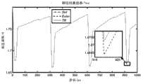
图7(a)和图7(b)分别是利用图1所示的方法对ibmpg1t实例进行瞬态仿真后其中一个电路节点n1_18333_5432的电压波形图和电压误差曲线图;Figure 7(a) and Figure 7(b) are the voltage waveform and voltage error curve of one of the circuit nodes n1_18333_5432 after the transient simulation of the ibmpg1t instance using the method shown in Figure 1;
图8是根据本发明第二实施例的集成电路供电网络全参数模型下瞬态分析系统的结构示意图。FIG. 8 is a schematic structural diagram of a transient analysis system under a full parameter model of an integrated circuit power supply network according to a second embodiment of the present invention.
具体实施方式Detailed ways
以下将结合附图及实施例来详细说明本发明的实施方式,借此对本发明如何应用技术手段来解决技术问题,并达成技术效果的实现过程能充分理解并据以实施。需要说明的是,只要不构成冲突,本发明中的各个实施例以及各实施例中的各个特征可以相互结合,所形成的技术方案均在本发明的保护范围之内。The implementation of the present invention will be described in detail below in conjunction with the accompanying drawings and examples, so as to fully understand and implement the process of how to apply technical means to solve technical problems and achieve technical effects in the present invention. It should be noted that, as long as there is no conflict, each embodiment and each feature in each embodiment of the present invention can be combined with each other, and the formed technical solutions are all within the protection scope of the present invention.
另外,在附图的流程图示出的步骤可以在诸如一组计算机可执行指令的计算机系统中执行,并且,虽然在流程图中示出了逻辑顺序,但是在某些情况下,可以以不同于此处的顺序执行所示出或描述的步骤。In addition, the steps shown in the flow diagrams of the figures may be performed in a computer system, such as a set of computer-executable instructions, and, although a logical order is shown in the flow diagrams, in some cases, the sequence may be different. The steps shown or described are performed in the order herein.
第一实施例first embodiment
本实施例的目的在于提出一种比该领域中其他方法更稳定、高效,且占用内存更少的全参数模型下供电网络瞬态分析方法,也就是在满足用户指定的求解精度情况下,以尽量少的运行时间、尽量少的内存消耗来完成对指定SPICE网表格式的供电网络节点电压降的瞬态分析。The purpose of this embodiment is to propose a transient analysis method for the power supply network under a full parameter model that is more stable and efficient than other methods in this field and takes up less memory, that is, when the solution accuracy specified by the user is satisfied, the The transient analysis of the voltage drop of the power supply network nodes in the specified SPICE netlist format is completed with as little running time as possible and as little memory consumption as possible.
为达到上述目的,本实施例提出的全参数模型下供电网络瞬态分析方法的流程图,具体如图1所示。In order to achieve the above purpose, the flow chart of the transient analysis method for the power supply network under the full parameter model proposed in this embodiment is specifically shown in FIG. 1 .
步骤S110(以下省略“步骤”二字)确定待分析的集成电路供电网络的全参数模型信息。Step S110 (the word "step" is omitted hereinafter) determines the full parameter model information of the integrated circuit power supply network to be analyzed.
在本实施例中,优选地,通过对待分析的集成电路供电网络的SPICE网表进行扫描来确定该集成电路供电网络的全参数模型信息。当然,并不限定SPICE格式,只要能够将待分析的电路的信息进行完整描述,那么其他格式,例如DEF/SPEF/DSPF文件格式也可以。In this embodiment, preferably, the full parameter model information of the integrated circuit power supply network to be analyzed is determined by scanning the SPICE netlist of the integrated circuit power supply network. Of course, the SPICE format is not limited, as long as the information of the circuit to be analyzed can be fully described, other formats, such as DEF/SPEF/DSPF file formats, are also acceptable.
通过两次扫描SPICE网表得到关于供电网络的信息,第一次扫描统计出该供电网络中电阻的数目和金属走线层数,然后基于统计结果建立哈希表。在第二次读入网表时从得到的哈希表中快速查询已经存储的电路节点。The information about the power supply network is obtained by scanning the SPICE netlist twice. The first scan counts the number of resistors and the number of metal wiring layers in the power supply network, and then builds a hash table based on the statistical results. When the netlist is read into the netlist for the second time, the stored circuit nodes are quickly queried from the obtained hash table.
需要说明的是,SPICE格式是一种工业界应用于描述电路元器件及其拓扑关系的标准格式。对于全参数的供电网络瞬态分析,其电路模型包含金属走线的电阻、供电电压源模型以及作为供电网络负载的吸纳电流源模型,电路输出是供电网络中各个电路节点每一时刻的电压值。It should be noted that the SPICE format is a standard format used in the industry to describe circuit components and their topological relationships. For the transient analysis of the full-parameter power supply network, the circuit model includes the resistance of metal traces, the model of the supply voltage source, and the model of the absorbing current source as the load of the power supply network. The output of the circuit is the voltage value of each circuit node in the power supply network at each moment .
如图2所示,其为一全参数的供电网络模型。片上金属走线被建模为集总电阻,其电感效应很小而被忽略(图中未示出);供电源被建模为标准电压源与一个封装电阻和封装电感串联的复合模型;作为负载的芯片工作单元被建模为一个复合的吸纳电流源模型,其包括描述工作单元开启的电流源以及单元内部的电容效应和描述电阻效应的内部电阻。As shown in Figure 2, it is a full parameter power supply network model. On-chip metal traces are modeled as lumped resistors with negligible inductive effects (not shown); the power supply is modeled as a composite model of a standard voltage source in series with a package resistor and package inductor; as The chip working unit of the load is modeled as a composite sinking current source model, which includes a current source describing the turning on of the working unit as well as the capacitive effect inside the unit and the internal resistance describing the resistive effect.
具体来说,如图3所示为一个典型的供电电压源模型,其考虑到了由芯片封装而引起的电学效应,封装效应被建模成了一个集总电感L和一个集总电阻r,因此使用到的供电源模型就是由一个标准的电压源Vdd与封装电感L和封装电阻r串联而成。为了便于形成仿真矩阵,需要对其进行变换,首先将封装电阻r分为两个阻值为


如图4所示为一个典型的复合吸纳电流源模型,实际上是在对作为负载的芯片单元进行仿真时,采用的一个复合的电路模型来描述其电学响应。其包括一个等效电阻Requiv与一个等效电容Cequiv进行串联之后再与一个等效的电流源Is进行并联,然后接入供电网络中。而对于实际接入供电网络中的VDD线网和GND线网来说,这个模型中等效电阻Requiv与等效电容Cequiv的顺序不同,但是这并不影响其电路响应,因此在实际仿真中只需要正确识别电流Is的方向即可。As shown in Figure 4, it is a typical composite sink current source model, which is actually a composite circuit model used to describe its electrical response when simulating the chip unit as a load. It includes an equivalent resistor Requiv connected in series with an equivalent capacitor Cequiv and then connected in parallel with an equivalent current source Is , and then connected to the power supply network. For the VDD line network and GND line network actually connected to the power supply network, the order of the equivalent resistance Requiv and the equivalent capacitance Cequiv in this model is different, but this does not affect its circuit response, so in the actual simulation It is only necessary to correctly identify the direction of the current Is .
步骤S120,基于全参数模型建立包含多个独立子电路的供电网络拓扑图。In step S120, a power supply network topology diagram including multiple independent sub-circuits is established based on the full parameter model.
具体地,基于全参数模型信息建立电路元件与电路节点之间的邻接表关系,然后利用邻接表关系构建包含多个独立子电路的供电网络拓扑图。Specifically, the adjacency list relationship between circuit elements and circuit nodes is established based on the full parameter model information, and then a power supply network topology diagram including multiple independent sub-circuits is constructed using the adjacency list relationship.
在利用邻接表关系构建包含多个独立子电路的供电网络拓扑图的步骤中,首先处理电路中的诸如节点短路或者是通孔电阻过小的情况,采用并查集的技术将上述节点进行等效,然后将每个等效后的节点所代表的原始节点上挂载的吸纳电流源进行合并,再将经上述处理的等效后的节点与未被忽略的电阻建立成连接拓扑图。In the step of using the adjacency list relationship to construct a power supply network topology diagram that includes multiple independent sub-circuits, firstly deal with the situation in the circuit such as node short circuit or too small via resistance, and use the technology of union search to divide the above nodes into equal Then combine the absorbing current sources mounted on the original nodes represented by each equivalent node, and then establish a connection topology diagram with the above-mentioned equivalent nodes and the resistances that have not been ignored.
由于供电网络中存在着互相独立而没有电气连接关系的若干子电路,因此可以采用深度优先搜索的方法识别出该图中的所有连通分支,并将识别出的连通分支作为独立子电路的连接拓扑图,利用此属性可并行地对每个子电路进行直流工作点分析以及瞬态分析。Since there are several sub-circuits that are independent of each other and have no electrical connection relationship in the power supply network, it is possible to use the depth-first search method to identify all connected branches in the graph, and use the identified connected branches as the connection topology of independent sub-circuits Figure, this property allows parallel analysis of the DC operating point and transient analysis of each subcircuit.
步骤S130,对供电网络拓扑图中的各个子电路并行进行直流工作点分析和瞬态分析得到各个子电路在每个时刻的电路节点电压分布。Step S130, performing DC operating point analysis and transient analysis on each sub-circuit in the topology diagram of the power supply network in parallel to obtain the circuit node voltage distribution of each sub-circuit at each moment.
具体来说,在第0时刻,对各个子电路进行直流工作点分析。进一步对于t=0时刻的直流工作点分析,可以将所有的储能元件忽略,也即是将电感短路,电容开路,然后建立静态分析矩阵方程和右端项GV=I,其中G是电导矩阵,V是待求的电路节点电压向量,I是吸纳电流源负载向量,求解此矩阵方程得到初始时刻t=0时电路节点的电压分布。Specifically, at
在第1时刻,采用欧拉离散差分法构建关于该子电路的RLC模型下的瞬态分析矩阵以及右端项,然后求解得到各个子电路的第1时刻的电路节点电压分布。在其他时刻,采用梯形离散差分法构建关于该子电路图的RLC模型下的各个时刻的瞬态分析矩阵以及右端项,然后求解得到各个子电路图的在各个时刻的电路节点电压分布。At the first moment, the Euler discrete-difference method is used to construct the transient analysis matrix and the right-hand term of the sub-circuit under the RLC model, and then the circuit node voltage distribution of each sub-circuit at the first moment is obtained by solving. At other times, use the trapezoidal discrete difference method to construct the transient analysis matrix and the right-hand term at each moment under the RLC model of the sub-circuit diagram, and then obtain the circuit node voltage distribution of each sub-circuit diagram at each moment.
需要说明的是,对于第一步的瞬态分析,即t=1时刻的瞬态分析,由于其前面只有一个时间点t=0时刻的分析结果可使用,因此必须采用Euler差分方式进行离散化,建立RLC模型下的瞬态矩阵方程和右端项,求解得到第一步的瞬态分析t=1时刻的电路节点的电压分布。It should be noted that, for the transient analysis of the first step, that is, the transient analysis at time t=1, since there is only one analysis result at the time point t=0 before it, it must be discretized by means of Euler difference , establish the transient matrix equation and the right-hand term under the RLC model, and solve to obtain the voltage distribution of the circuit node at the moment t=1 of the transient analysis in the first step.
而后t=2时刻以及其他的时间点,由于其前面已经有两个时间点(t-2)时刻和(t-1)时刻的分析结果可以使用,因此采用了更高精度的梯形差分方式进行离散化,建立RLC模型下的瞬态矩阵方程和右端项,求解得到t=2时刻以及剩余时间点瞬态仿真的电路节点的电压分布。Then at time t=2 and other time points, because the analysis results of two time points (t-2) and (t-1) are available before it, a higher-precision trapezoidal difference method is used to carry out For discretization, the transient matrix equation and the right-hand term under the RLC model are established, and the voltage distribution of the circuit nodes of the transient simulation at t=2 and the remaining time points is obtained by solving the solution.
下面详细说明如何来建立瞬态分析方程(瞬态矩阵方程和右端项)。The following details how to establish the transient analysis equation (transient matrix equation and right-hand term).
供电网络的瞬态分析指的是在给定随时间变化的电流负载情况下,求出供电网络电路节点上随时间变化的电压波形。全参数RLC模型下供电网络的瞬态分析,实质上是去求解一个大规模的常微分方程,实际中需要对其在时间域上进行离散化,然后求解一系列的差分代数方程。瞬态分析面临的最大问题在于,时域上离散差分后会形成一系列的大规模代数方程需要求解,需要非常长的仿真周期。The transient analysis of the power supply network refers to finding the voltage waveform on the circuit node of the power supply network that changes with time under the given current load that changes with time. The transient analysis of the power supply network under the full-parameter RLC model is essentially to solve a large-scale ordinary differential equation. In practice, it needs to be discretized in the time domain, and then solve a series of differential algebraic equations. The biggest problem faced by transient analysis is that after discrete difference in time domain, a series of large-scale algebraic equations need to be solved, which requires a very long simulation cycle.
对于一个含有n个电路节点的RLC模型的供电网络,采用基于KCL定律和KVL定律的节点分析方法(MNA),在只保留流过电感支路的电流变量时,该系统可被形式化为For a power supply network with an RLC model containing n circuit nodes, using the node analysis method (MNA) based on KCL law and KVL law, when only the current variable flowing through the inductive branch is retained, the system can be formalized as
其中,n是供电网络的电路节点数目,vn是待求的电路节点电压向量,il是流过电感支路的电流向量,ii是吸纳电流源向量,并且
上述微分方程经过离散差分之后形成一系列矩阵形式的代数方程,在数值领域中已经发展出许多种解法,主要分为两大类:直接求解器和迭代求解器。由于直接求解器是对矩阵进行分解,然后通过回代求的数值结果,而对于瞬态仿真来说,一旦仿真矩阵形成之后,只需一次矩阵分解,后续的每一时刻的分析就可以通过回代的形式来得到结果,因此对于瞬态分析来说,直接求解器更容易受到青睐。The above differential equations form a series of algebraic equations in the form of a matrix after discrete differences. Many solutions have been developed in the numerical field, which are mainly divided into two categories: direct solvers and iterative solvers. Since the direct solver decomposes the matrix, and then returns the numerical results obtained by interrogation, for transient simulation, once the simulation matrix is formed, only one matrix decomposition is required, and subsequent analysis at each moment can be performed by returning For transient analysis, direct solvers are more likely to be favored.
对于上述微分方程形式化后的代数矩阵方程,主流的求解方法是对其系数矩阵进行LU分解,同时衍生出一些列基于重排序技术来减少矩阵分解时的非零元填入,以降低求解器的内存消耗,但是对于大规模的供电网络瞬态分析来说,其节点数目可达到数百万甚至数亿,对其进行瞬态分析时消耗的内存急剧增长。For the above-mentioned algebraic matrix equation after the formalization of the differential equation, the mainstream solution method is to perform LU decomposition on the coefficient matrix, and at the same time derive some columns based on the reordering technology to reduce the non-zero element filling in the matrix decomposition, so as to reduce the solver However, for large-scale transient analysis of power supply networks, the number of nodes can reach millions or even hundreds of millions, and the memory consumption for transient analysis increases sharply.
而本实施例通过以下分析方法,极大地降低了瞬态分析的内存消耗,同时也提高了求解的效率。注意到上述微分方程离散差分后的代数矩阵方程具有稀疏、正定但非对称的特点,如果采用直接求解方法则必须对电导矩阵进行LU分解,形成两个矩阵分解因子L和U,其对内存的需求非常高。本实施例基于此,将上述微分方程重新形式化,然后进行离散差分形成的代数矩阵方程具有稀疏、正定且对称的特点,此时便可优选采用高效的乔莱斯基分解求解器Cholmod(关于该求解器的具体内容,详见网址http://www.cise.ufl.edu/research/sparse/cholmod中的《CHOLMOD:supernodal sparseCholesky factorization and update/downdate》),其只需分解得到一个矩阵因子L,极大地节省了求解器的内存,同时也提高了矩阵分解的效率。However, this embodiment greatly reduces the memory consumption of the transient analysis and improves the efficiency of the solution through the following analysis method. Note that the algebraic matrix equation after discrete difference of the above differential equation is sparse, positive definite but asymmetrical. If the direct solution method is used, the conductance matrix must be decomposed by LU to form two matrix decomposition factors L and U, which have a significant impact on memory The demand is very high. Based on this, this embodiment re-formalizes the above differential equation, and then the algebraic matrix equation formed by discrete difference has the characteristics of sparse, positive definite and symmetric. At this time, the efficient Cholesky decomposition solver Cholmod (about For the specific content of the solver, see "CHOLMOD: supernodal sparse Cholesky factorization and update/downdate" in the website http://www.cise.ufl.edu/research/sparse/cholmod), which only needs to be decomposed to obtain a matrix factor L, which greatly saves the memory of the solver, and also improves the efficiency of matrix decomposition.
注意到上述微分方程正是由于引入了额外电感支路的电流变量才导致了形成的代数矩阵方程的非对称化,这里通过重新形式化将其消去。首先,对上述微分方程采用离散差分,采用欧拉方式或者梯形方式皆可,为了便于描述,这里暂时采用欧拉差分方式。对于上述微分方程,给定离散步长h,则t时刻与(t+h)时刻的电流电压关系可以描述为如下矩阵方程It is noticed that the above differential equation is asymmetrical to the formed algebraic matrix equation because of the introduction of the current variable of the extra inductance branch, which is eliminated by re-formalization here. Firstly, discrete difference is used for the above differential equation, either Euler method or trapezoidal method can be used. For the convenience of description, Euler difference method is temporarily used here. For the above differential equation, given the discrete step length h, the relationship between current and voltage at time t and time (t+h) can be described as the following matrix equation
将t时刻的电压变量vn(t)和电流变量il(t)移到等式右端,可以得到Moving the voltage variable vn (t) and current variable il (t) at time t to the right side of the equation, we can get
将上述分块形式的矩阵方程展开,消去电流变量ii(t+h),可以得到Expand the matrix equation in block form above, and eliminate the current variable ii (t+h), we can get
并且注意到
至此,从上式可以看出,一旦知道了t时刻的电压分布,则可以通过求解上式得到(t+h)时刻的电压分布,并且稀疏矩阵
同样,一旦知道了t时刻的电压分布,则可以通过求解上式得到(t+h)时刻的电压分布,并且系数矩阵


由于其中的
至此,本实施例提出的将MNA方程重新形式化为对称形式的代数矩阵方程的方法,使得RLC模型下的瞬态分析可以采用对称的乔莱斯基求解器,在内存消耗和运行时间方面都有着很大的提高。So far, the method of re-formalizing the MNA equation into a symmetric algebraic matrix equation proposed in this embodiment enables the transient analysis under the RLC model to use a symmetric Cholesky solver, which is both memory consumption and running time. There has been a great improvement.
本实施例优选采用两个求解器:迭代求解器AMGPCG(Algebraic MultigridPreconditioned Conjugate Gradient Method,基于网格点聚合的代数多重网格预条件的共轭梯度迭代求解器)和直接求解器Cholmod。其中,迭代求解器AMGPCG在矩阵层次上采用纯代数的网格点聚合方法对粗网格与细网格进行映射,同时在不同层次的粗化网格上采用克雷洛夫子空间加速策略,并其作为隐式的预条件子用来提高共轭梯度算法的收敛稳定性。进一步,关于该求解器的具体内容,详见2011年IEEE/ACM计算机辅助设计国际会议中的《PowerRush:A Linear Simulator for Power Grid》。由于Cholmod的特点是只需进行一次对阵矩阵分解即可对多右端项的系统进行求解,而AMGPCG则无此特点,但是对于只需一次求解的情形,AMGPCG求解器要比Cholmod的运行速度和内存要好很多,因此在t=0时刻的直流工作点分析采用的是AMGPCG求解器。In this embodiment, two solvers are preferably used: an iterative solver AMGPCG (Algebraic MultigridPreconditioned Conjugate Gradient Method, an algebraic multigrid preconditioned conjugate gradient iterative solver based on grid point aggregation) and a direct solver Cholmod. Among them, the iterative solver AMGPCG uses a pure algebraic grid point aggregation method at the matrix level to map the coarse grid and the fine grid, and at the same time uses the Krylov subspace acceleration strategy on the coarse grid at different levels, and It is used as an implicit preconditioner to improve the convergence stability of the conjugate gradient algorithm. Further, for the specific content of the solver, see "PowerRush: A Linear Simulator for Power Grid" in the 2011 IEEE/ACM International Conference on Computer-Aided Design. Since the characteristic of Cholmod is that it can solve the system with multiple right-hand items only by performing a matrix decomposition once, and AMGPCG does not have this characteristic, but for the case of only one solution, the AMGPCG solver is faster than Cholmod in terms of speed and memory. Much better, so the DC operating point analysis at t = 0 uses the AMGPCG solver.
而且由于离散差分方式的不同,第1步的瞬态分析t=1时刻与t=2时刻以及其他的时间点的瞬态分析矩阵并不相同,因此第1步的瞬态仿真t=1时刻仍然采用AMGPCG求解器,而t=2时刻以及其他的时间点则采用Cholmod求解器。Moreover, due to the difference in the discrete difference method, the transient analysis matrix at the time t=1 of the first step is different from that at the time t=2 and at other time points, so the transient simulation of the first step at the time t=1 The AMGPCG solver is still used, while the Cholmod solver is used at t=2 and other time points.
步骤S140,输出各个子电路在每个时刻的电路节点电压分布。Step S140, outputting the circuit node voltage distribution of each sub-circuit at each moment.
本发明方法首先解析例如SPICE格式的网表,将供电网络中的电学元件以及节点信息存储到高效的数据结构中;然后,在供电网络特有的几何拓扑性质基础上,根据节点分析方法的原理,建立供电网络的静态仿真矩阵以及右端电流向量,采用AMGPCG求解器进行直流分析,得到各个电路节点的初始电压分布;最后,建立供电网络的瞬态仿真矩阵以及右端电流向量,采用基于乔莱斯基分解的直接求解器Cholmod求解后续每个时间点上供电网络节点电压向量,并将其输出。The method of the present invention first parses a netlist such as SPICE format, and stores the electrical components and node information in the power supply network into an efficient data structure; then, on the basis of the unique geometric topology properties of the power supply network, according to the principle of the node analysis method, Establish the static simulation matrix of the power supply network and the current vector at the right end, and use the AMGPCG solver for DC analysis to obtain the initial voltage distribution of each circuit node; finally, establish the transient simulation matrix and the current vector at the right end of the power supply network, using the Cholesky-based The decomposed direct solver Cholmod solves the power supply network node voltage vector at each subsequent time point and outputs it.
本实施例通过上述步骤能够对全参数模型下的供电网络进行快速精确的瞬态电压降分析,尤其是在内存消耗方面,有很大程度的提高。In this embodiment, through the above steps, fast and accurate transient voltage drop analysis can be performed on the power supply network under the full parameter model, especially in terms of memory consumption, which is greatly improved.
仿真示例Simulation example
下面通过一仿真示例来进一步说明本发明实施例的特征和优点。The features and advantages of the embodiment of the present invention are further described below through a simulation example.
对于输入SPICE网表格式的供电网络,首先通过SPICE解析器将其读入到内部的数据结构中,然后针对每个子电路分别并行地进行仿真,也即是直流工作点分析和瞬态分析。对于直流工作点分析,首先建立静态模型,形成仿真矩阵和右端项,然后采用AMGPCG求解器对其进行求解得到电路节点的初始电压分布;然后建立瞬态模型,对于t=0的时刻采用欧拉(Euler)差分法进行离散作为启动,形成仿真矩阵和右端项,同样采用AMGPCG求解器求解得到电路节点的电压分布,而对于后续的时间点则采用梯形差分法进行离散,形成仿真矩阵和右端项,采用Cholmod求解器求解得到每个时刻电路节点的电压分布;最后输出电路的瞬态电压波形。具体来说,包括以下步骤。For the power supply network input in SPICE netlist format, it is first read into the internal data structure through the SPICE parser, and then each sub-circuit is simulated in parallel, that is, DC operating point analysis and transient analysis. For the analysis of the DC operating point, first establish a static model, form the simulation matrix and the right-hand term, and then use the AMGPCG solver to solve it to obtain the initial voltage distribution of the circuit nodes; then establish a transient model, and use Euler for the time t=0 The (Euler) difference method is used as a starting point for discretization to form a simulation matrix and the right-hand term. The AMGPCG solver is also used to solve the voltage distribution of the circuit nodes. For subsequent time points, the trapezoidal difference method is used for discretization to form a simulation matrix and the right-hand term. , use the Cholmod solver to solve the voltage distribution of the circuit nodes at each moment; finally output the transient voltage waveform of the circuit. Specifically, the following steps are included.
具体的仿真步骤如下:The specific simulation steps are as follows:
(1)读取SPICE网表格式的供电网络;(1) Read the power supply network in SPICE netlist format;
(2)构建电路拓扑图,识别出供电网络中无电气连接关系的电路子图,分别并行地对他们进行仿真分析;(2) Construct the circuit topology diagram, identify the circuit subgraphs without electrical connection in the power supply network, and simulate and analyze them in parallel;
(3)在t=0时刻进行直流工作点分析(静态分析):(3) Perform DC operating point analysis (static analysis) at time t=0:
(3.1)构建静态分析矩阵以及右端项;(3.1) Construct the static analysis matrix and the right-hand term;
(3.2)调用AMGPCG求解器求解得到在t=0时刻的电路节点电压分布;(3.2) Call the AMGPCG solver to solve the circuit node voltage distribution at t=0 moment;
(4)在t=1时刻采用Euler离散差分方式进行第1步的瞬态仿真:(4) At the time t=1, the Euler discrete difference method is used to perform the transient simulation of the first step:
(4.1)构建瞬态仿真矩阵以及右端项;(4.1) Construct the transient simulation matrix and the right-hand term;
(4.2)调用AMGPCG求解器求解得到在t=1时刻的电路节点电压分布;(4.2) Call the AMGPCG solver to solve the circuit node voltage distribution at t=1 moment;
(5)在t=2时刻以及剩余的时间点采用梯形离散差分方式进行瞬态仿真:(5) At t=2 and the rest of the time points, the trapezoidal discrete difference method is used for transient simulation:
(5.1)重新构建瞬态仿真矩阵以及每一时刻的右端项;(5.1) Reconstruct the transient simulation matrix and the right-hand term at each moment;
(5.2)调用Cholmod求解器求解得到每一时刻电路节点电压分布。(5.2) Call the Cholmod solver to solve the circuit node voltage distribution at each moment.
在瞬态仿真步骤中,Euler离散差分方式只需前一个时间点的结果,而梯形离散差分方式需要前两个时间点的结果,其在时间轴上的描述可见图5所示,以前4步的瞬态仿真为例,具体来说包括如下步骤:In the transient simulation step, the Euler discrete-difference method only needs the results of the previous time point, while the trapezoidal discrete-difference method requires the results of the first two time points. Its description on the time axis can be seen in Figure 5, the first 4 steps For example, the transient simulation includes the following steps:
(1)在t=0起始时刻进行瞬态分析;(1) Transient analysis is performed at the initial moment of t=0;
(2)在t=1时刻进行第1步瞬态分析,采用Euler离散差分方式(图中Euler),其需要用到t=0时刻的节点电压分布;(2) Perform the first step of transient analysis at time t=1, using the Euler discrete difference method (Euler in the figure), which needs to use the node voltage distribution at time t=0;
(3)在t=2时刻进行第2步瞬态分析,采用梯形离散差分方式(图中TR),其需要用到t=0时刻以及t=1时刻的节点电压分布;(3) Perform the second-step transient analysis at time t=2, using the trapezoidal discrete difference method (TR in the figure), which needs to use the node voltage distribution at time t=0 and time t=1;
(4)在t=3时刻进行第3步瞬态分析,采用梯形离散差分方式,其需要用到t=1时刻以及t=2时刻的节点电压分布。(4) The third step of transient analysis is performed at time t=3, and the trapezoidal discrete difference method is used, which needs to use the node voltage distribution at time t=1 and time t=2.
随后,采用梯形离散差分方式对剩余的时间点进行仿真,直至到达所要求的时刻为止。Subsequently, the remaining time points are simulated using the trapezoidal discrete difference method until the required time is reached.
同时,由于原始供电网络中存在无电气连接关系的子电路,本发明实施例采用深度优先的方法将其识别,然后分别对每个子电路同时进行仿真分析以提高仿真器的仿真速度。At the same time, since there are sub-circuits without electrical connections in the original power supply network, the embodiment of the present invention adopts a depth-first method to identify them, and then performs simulation analysis on each sub-circuit at the same time to improve the simulation speed of the simulator.
在对每个子电路进行并行仿真时,需要为每个子电路并行仿真进行线程分配,对所有子电路的节点数目进行排序,根据可用的线程数目,尽量平均分配这些子电路到指定的线程上进行仿真。When performing parallel simulation of each sub-circuit, it is necessary to allocate threads for parallel simulation of each sub-circuit, sort the number of nodes of all sub-circuits, and distribute these sub-circuits to the designated threads evenly for simulation according to the number of available threads. .
如图6所示,一般的供电网络中都存在着若干个自然分割的子电路,它们之间没有任何电气连接关系,比如包括4个子电路,包括3个VDD线网(图中所示的子线网#1、子线网#2和子线网#3)和1个GND线网(图中所示的子线网#0),分别将每个子电路放在一个线程中,采用多线程技术来对整个仿真进行加速。最直接的方法便是一个子电路对应一个线程,如图所示,将子线网#0、子线网#1、子线网#2和子线网#3分别对应线程0、线程1、线程2和线程3。但是在实际应用中存在着线程不够用、内存峰值过高或者线程闲置等待的情况,因此需要对其进行简单的线程调度分配。As shown in Figure 6, there are several naturally divided sub-circuits in the general power supply network, without any electrical connection between them, for example, including 4 sub-circuits, including 3 VDD line networks (the sub-circuits shown in the figure
由供电网本身的特点可知,GND线网中的电路节点数目一般与VDD线网中的电路节点数目相当,但VDD线网一般都被分作若干个无电气连接关系的子电路,而GND线网只对应着一个子电路,因此最简单的方法便是采用一个线程来仿真GND线网,如图6所示,采用线程0来仿真子线网#0,而采用另外一个线程分别串行地仿真所有VDD线网中的子电路,如图6所示,采用线程1来仿真子线网#1、#2和#3。这样以来内存峰值不会过高,而且不易存在线程闲置等待的情况。更一般的情形是,首先对所有子电路的节点数目进行排序,然后根据可用的线程数目,尽量平均分配这些子电路到指定的线程上进行仿真。According to the characteristics of the power supply network itself, the number of circuit nodes in the GND line network is generally equivalent to the number of circuit nodes in the VDD line network, but the VDD line network is generally divided into several sub-circuits without electrical connections, and the GND line The net only corresponds to one sub-circuit, so the easiest way is to use one thread to simulate the GND net, as shown in Figure 6, use
最后,输出电路的瞬态电压波形。具体地,根据上述瞬态仿真存储下来的每个时间点上所有节点电压值输出到指定的文件中,完成整个瞬态仿真流程。Finally, output the transient voltage waveform of the circuit. Specifically, all node voltage values at each time point stored according to the above transient simulation are output to a specified file to complete the entire transient simulation process.
如图7(a)所示为ibmpg1t中名称为n1_18333_5432的节点的波形图,仿真周期为1ns,离散步长为1ps,因此图中所示为1001个时刻的电压波形,在该图中分别以“Std”、“Euler”和“TR”来表示标准解、欧拉差分形式下的仿真结果和梯形差分形式下的仿真结果。同时,如图7(b)所示,还给出了采用Eluer差分和梯形差分形式下的仿真精度,与标准解进行对比可以发现采用梯形差分方式进行仿真得到的解的精度基本上比采用Eluer差分方式进行仿真得到的解的精度要高一个数量级。Figure 7(a) shows the waveform diagram of the node named n1_18333_5432 in ibmpg1t, the simulation cycle is 1ns, and the discrete step length is 1ps, so the voltage waveform at 1001 moments is shown in the figure. "Std", "Euler" and "TR" represent the standard solution, the simulation result under the Euler difference form and the simulation result under the trapezoidal difference form. At the same time, as shown in Figure 7(b), the simulation accuracy of Eluer difference and trapezoidal difference is also given. Compared with the standard solution, it can be found that the accuracy of the solution obtained by using trapezoidal difference is basically higher than that of Eluer The accuracy of the solution obtained by simulation in the differential mode is an order of magnitude higher.
如下表1所示,为分别测试子电路ibmpg1t~ibmpgt6t时,运行时间和内存消耗情况。Table 1 below shows the running time and memory consumption when the sub-circuits ibmpg1t~ibmpgt6t are tested respectively.
表1Table 1


上述仿真示例的仿真器采用C/C++语言实现,在一台Intel Xeon E5506CPU2.13Hz和24GB内存的Liunx服务器上进行测试,测试实例采用美国IBM公司提供的实际设计中针对瞬态分析的供电网络ibmpg1t~ibmpgt6t测试集。对上述示例,在保证0.01mV的求解精度下,可以快速求解得到供电网络的瞬态电压降,并且内存消耗几乎是传统的LU求解器的一半,运行时间也得到了提升,尤其是多线程加速情况下整个仿真器的速度得到了很大的提升。The emulator of the above simulation example is implemented in C/C++ language, and tested on a Liunx server with Intel Xeon E5506CPU2.13Hz and 24GB memory. The test example uses the power supply network ibmpg1t for transient analysis in the actual design provided by IBM Corporation of the United States ~ibmpgt6t test set. For the above example, under the guaranteed solution accuracy of 0.01mV, the transient voltage drop of the power supply network can be quickly solved, and the memory consumption is almost half that of the traditional LU solver, and the running time has also been improved, especially the multi-thread acceleration The speed of the entire emulator has been greatly improved.
通过采用工业界标准的SPICE格式的设计实例进行仿真测试,测试结果表明了本实施例的有效性,对供电网络在全参数模型下进行瞬态分析时,有着很好的稳定性,尤其是内存使用方面,节省了近一半的内存消耗。Through the simulation test using the design example of the industry standard SPICE format, the test results show the effectiveness of this embodiment, and it has good stability when performing transient analysis on the power supply network under the full parameter model, especially the memory In terms of usage, nearly half of the memory consumption is saved.
第二实施例second embodiment
图8是根据本发明第二实施例的集成电路供电网络全参数模型下瞬态分析系统的结构示意图。FIG. 8 is a schematic structural diagram of a transient analysis system under a full parameter model of an integrated circuit power supply network according to a second embodiment of the present invention.
如图8所示,本系统包括全参数模型信息确定模块80、与其连接的网络拓扑图建立模块81、和建立模块81连接的分析模块82以及输出模块83。As shown in FIG. 8 , the system includes a full parameter model
全参数模型信息确定模块80,其确定待分析的集成电路供电网络的全参数模型信息。A full parameter model
具体地,该模块80通过对待分析的集成电路供电网络的SPICE网表进行扫描来确定该集成电路供电网络的全参数模型信息。Specifically, the
网络拓扑图建立模块81,其基于全参数模型信息建立包含多个独立子电路的供电网络拓扑图。A network topology
该模块81基于全参数模型信息建立电路元件与电路节点之间的邻接表关系,然后利用邻接表关系构建包含多个独立子电路的供电网络拓扑图。并且,还用于将网络模型信息中供电源模型的所有电压源转换成电流源以及识别网络模型信息中复合吸纳电流源模型的电流方向。The
进一步,该模块81采用并查集将邻接表关系中设定属性的电路节点进行等效,设定属性的电路节点包括短路或通孔电阻小于设定值的电路节点;将每个等效后的电路节点所代表的原电路节点上挂载的吸纳电流源进行合并;将执行吸纳电流源合并后的每个等效后的电路节点与未被忽略的电阻建立成连接拓扑图;以及采用深度优先搜索算法识别出所述连接拓扑图中无电气连接关系的各个独立子电路,以得到供电网络拓扑图。Further, the
分析模块82,其对供电网络拓扑图中的各个子电路并行进行直流工作点分析和瞬态分析得到各个子电路在各个时刻的电路节点电压分布。An
在分析模块82中,进一步包括直流工作点分析单元82a和瞬态分析单元82b。In the
直流工作点分析单元82a,其对于供电网络拓扑图中的各个子电路,在第0时刻,对该子电路进行直流工作点分析。具体地,该单元82a忽略该子电路中所有的储能元件,构建关于该子电路的静态分析矩阵以及右端项,然后,利用迭代求解器求解得到该子电路在第0时刻的电路节点电压分布,优选利用AMGPCG求解器。The DC operating
瞬态分析单元82b,其在第1时刻,采用欧拉离散差分法构建关于该子电路的RLC模型下的瞬态分析矩阵以及右端项,然后求解得到该子电路的第1时刻的电路节点电压分布。瞬态分析矩阵以及右端项可如下式所示:The
其中,vn(t)和vn(t+h)分别是第t时刻和第t+h时刻电路节点电压向量,il(t)是第t时刻流过电感支路的电流向量,ii(t+h)是第t+h时刻吸纳电流源向量,并且

瞬态分析单元82b,利用迭代求解器求解得到第1时刻的电路节点电压分布,优选利用AMGPCG求解器。The
在其他时刻,瞬态分析单元82b,采用梯形离散差分法构建关于该子电路的RLC模型下的各个时刻的瞬态分析矩阵以及右端项,然后求解得到该子电路的在各个时刻的电路节点电压分布。瞬态分析矩阵以及右端项可如下式所示:At other moments, the
其中,ii(t)和ii(t+h)分别是第t时刻和第t+h时刻吸纳电流源向量。Wherein, ii (t) and ii (t+h) are the vectors of the absorbing current source at the tth time and the t+h time, respectively.
瞬态分析单元82b,利用直接求解器求解得到每个时刻电路节点电压分布,优选利用Cholmod求解器。The
输出模块83,其输出电路的瞬态电压波形。具体地,将分析模块82存储下来的每个时间点上所有节点电压值输出到指定的文件中。An
通过本实施例的系统,可以对全参数模型下的供电网络进行快速精确的瞬态电压降分析,尤其是在内存消耗方面,相比以往的仿真器有着很大程度的提高。Through the system of this embodiment, fast and accurate transient voltage drop analysis can be performed on the power supply network under the full parameter model, especially in terms of memory consumption, which is greatly improved compared with previous simulators.
本领域的技术人员应该明白,上述的本发明的各模块或各步骤可以用通用的计算装置来实现,它们可以集中在单个的计算装置上,或者分布在多个计算装置所组成的网络上,可选地,它们可以用计算装置可执行的程序代码来实现,从而,可以将它们存储在存储装置中由计算装置来执行,或者将它们分别制作成各个集成电路模块,或者将它们中的多个模块或步骤制作成单个集成电路模块来实现。这样,本发明不限制于任何特定的硬件和软件结合。Those skilled in the art should understand that each module or each step of the present invention described above can be realized by a general-purpose computing device, and they can be concentrated on a single computing device, or distributed on a network formed by a plurality of computing devices, Optionally, they can be implemented with program codes executable by computing devices, thus, they can be stored in storage devices and executed by computing devices, or they can be made into individual integrated circuit modules, or multiple of them Each module or step is realized as a single integrated circuit module. As such, the present invention is not limited to any specific combination of hardware and software.
虽然本发明所揭露的实施方式如上,但所述的内容只是为了便于理解本发明而采用的实施方式,并非用以限定本发明。任何本发明所属技术领域内的技术人员,在不脱离本发明所揭露的精神和范围的前提下,可以在实施的形式上及细节上作任何的修改与变化,但本发明的专利保护范围,仍须以所附的权利要求书所界定的范围为准。Although the embodiments disclosed in the present invention are as above, the described content is only an embodiment adopted for the convenience of understanding the present invention, and is not intended to limit the present invention. Anyone skilled in the technical field to which the present invention belongs can make any modifications and changes in the form and details of the implementation without departing from the spirit and scope disclosed by the present invention, but the patent protection scope of the present invention, The scope defined by the appended claims must still prevail.
Claims (11)
Translated fromChinese


Priority Applications (1)
| Application Number | Priority Date | Filing Date | Title |
|---|---|---|---|
| CN201310152859XACN103207941A (en) | 2013-04-27 | 2013-04-27 | Transient analysis method and transient analysis system under integrated circuit power supply network full-parameter model |
Applications Claiming Priority (1)
| Application Number | Priority Date | Filing Date | Title |
|---|---|---|---|
| CN201310152859XACN103207941A (en) | 2013-04-27 | 2013-04-27 | Transient analysis method and transient analysis system under integrated circuit power supply network full-parameter model |
Publications (1)
| Publication Number | Publication Date |
|---|---|
| CN103207941Atrue CN103207941A (en) | 2013-07-17 |
Family
ID=48755161
Family Applications (1)
| Application Number | Title | Priority Date | Filing Date |
|---|---|---|---|
| CN201310152859XAPendingCN103207941A (en) | 2013-04-27 | 2013-04-27 | Transient analysis method and transient analysis system under integrated circuit power supply network full-parameter model |
Country Status (1)
| Country | Link |
|---|---|
| CN (1) | CN103207941A (en) |
Cited By (27)
| Publication number | Priority date | Publication date | Assignee | Title |
|---|---|---|---|---|
| CN105451445A (en)* | 2014-08-29 | 2016-03-30 | 展讯通信(上海)有限公司 | Method of designing power supply network for printed circuit board |
| CN105447242A (en)* | 2015-11-17 | 2016-03-30 | 西安华芯半导体有限公司 | Method for analyzing state of power supply network of integrated circuit in real time |
| CN105631105A (en)* | 2015-12-24 | 2016-06-01 | 北京航空航天大学 | Cable equivalent circuit modeling method containing applied field coupling |
| CN105912811A (en)* | 2016-05-03 | 2016-08-31 | 山东大学 | Simulation method for analog and digital hybrid circuit |
| CN107153750A (en)* | 2017-06-12 | 2017-09-12 | 北京工业大学 | Supply network electromigration reliability analysis method on a kind of piece based on physical model |
| CN107305535A (en)* | 2016-04-19 | 2017-10-31 | 全球能源互联网研究院 | A kind of method that accelerating circuit network state Equation Iterative is solved |
| CN108170923A (en)* | 2017-12-21 | 2018-06-15 | 北京工业大学 | A kind of on piece metal interconnecting wires net electromigration reliability analysis method of feature based function |
| CN108614909A (en)* | 2016-12-13 | 2018-10-02 | 台湾积体电路制造股份有限公司 | Method for estimating power supply noise of power distribution network (PDN) of circuit design |
| CN109063390A (en)* | 2018-09-29 | 2018-12-21 | 大连大学 | A kind of computer-implemented method of micro-fluidic dilution gradient network generator |
| CN109829474A (en)* | 2018-12-27 | 2019-05-31 | 北京邮电大学 | A kind of circuit diagram recognition methods |
| CN109829216A (en)* | 2019-01-22 | 2019-05-31 | 天津大学 | A kind of spacer units model equivalent method for power system real-time simulation |
| CN111553120A (en)* | 2020-05-12 | 2020-08-18 | 北京华大九天软件有限公司 | Method for generating SPICE netlist of digital circuit local clock network |
| CN111597767A (en)* | 2020-04-29 | 2020-08-28 | 东南大学 | Random nanowire network topology analysis and electrical property simulation method |
| CN112214955A (en)* | 2020-10-13 | 2021-01-12 | 天津飞腾信息技术有限公司 | Method for extracting power model parameters of very large scale integrated circuit chip |
| CN112257365A (en)* | 2020-12-08 | 2021-01-22 | 南京集成电路设计服务产业创新中心有限公司 | Method for establishing timing diagram in parallel based on geometric information |
| CN113128157A (en)* | 2021-04-22 | 2021-07-16 | 北京华大九天科技股份有限公司 | Method and device for solving high-impedance node non-convergence in analog circuit simulation |
| CN113326671A (en)* | 2021-06-15 | 2021-08-31 | 深圳华大九天科技有限公司 | Method for calculating circuit equation node current of linear resistor in circuit |
| CN113435157A (en)* | 2021-07-08 | 2021-09-24 | 苏州悦谱半导体有限公司 | Method for analyzing industrial graphic computer-aided manufacturing network data |
| CN113536722A (en)* | 2021-07-08 | 2021-10-22 | 北京华大九天科技股份有限公司 | Method for parameter evaluation based on dependency relationship |
| CN113673192A (en)* | 2021-10-22 | 2021-11-19 | 南京集成电路设计服务产业创新中心有限公司 | Parallel accelerated extraction method for SPEF parasitic parameters of ultra-large scale integrated circuit |
| CN114186528A (en)* | 2021-12-06 | 2022-03-15 | 成都华大九天科技有限公司 | IRdrop simulation method of large-scale array circuit |
| CN114185280A (en)* | 2021-12-06 | 2022-03-15 | 国网湖南省电力有限公司 | Energy storage power station semi-physical real-time simulation architecture building method based on embedded system |
| CN114722760A (en)* | 2022-04-22 | 2022-07-08 | 广州大学 | SPICE circuit network table generation method for assisting in circuit parameter optimization |
| CN116227612A (en)* | 2022-12-07 | 2023-06-06 | 阿里巴巴达摩院(杭州)科技有限公司 | Equivalent capacitance determining method and computer equipment |
| CN116258111A (en)* | 2023-05-15 | 2023-06-13 | 贝叶斯电子科技(绍兴)有限公司 | Static analog integrated circuit layout analysis method |
| CN118171623A (en)* | 2024-05-11 | 2024-06-11 | 杭州芯晓电子科技有限公司 | Power supply network analysis method and system based on distributed computing platform |
| CN118551715A (en)* | 2024-07-22 | 2024-08-27 | 杭州行芯科技有限公司 | Circuit processing method and device for analyzing circuit performance and electronic equipment |
Citations (2)
| Publication number | Priority date | Publication date | Assignee | Title |
|---|---|---|---|---|
| CN1431704A (en)* | 2003-02-28 | 2003-07-23 | 清华大学 | Solving method for transient analysis of power source network based on equivalent circuit |
| CN102663166A (en)* | 2011-12-08 | 2012-09-12 | 清华大学 | Method and system for simulating on-chip power supply network |
- 2013
- 2013-04-27CNCN201310152859XApatent/CN103207941A/enactivePending
Patent Citations (2)
| Publication number | Priority date | Publication date | Assignee | Title |
|---|---|---|---|---|
| CN1431704A (en)* | 2003-02-28 | 2003-07-23 | 清华大学 | Solving method for transient analysis of power source network based on equivalent circuit |
| CN102663166A (en)* | 2011-12-08 | 2012-09-12 | 清华大学 | Method and system for simulating on-chip power supply network |
Non-Patent Citations (3)
| Title |
|---|
| JIANLEI YANG 等: "《2011 IEEE/ACM International Conference on Computer-Aided Design (ICCAD)》", 10 November 2011, article "PowerRush : A Linear Simulator for Power Grid", pages: 482-487* |
| JIANLEI YANG 等: "《2012 IEEE/ACM International Conference on Computer-Aided Design(ICCAD)》", 8 November 2012, article "PowerRush:Efficient Transient Simulation for Power Grid Analysis"* |
| JIANLEI YANG 等: "《2012 IEEE/ACM International Conference on Computer-Aided Design(ICCAD)》", 8 November 2012, article "PowerRush:Efficient Transient Simulation for Power Grid Analysis", pages: 653-659* |
Cited By (43)
| Publication number | Priority date | Publication date | Assignee | Title |
|---|---|---|---|---|
| CN105451445A (en)* | 2014-08-29 | 2016-03-30 | 展讯通信(上海)有限公司 | Method of designing power supply network for printed circuit board |
| CN105451445B (en)* | 2014-08-29 | 2019-01-22 | 展讯通信(上海)有限公司 | A kind of design method of printed circuit board supply network |
| CN105447242B (en)* | 2015-11-17 | 2019-01-15 | 西安紫光国芯半导体有限公司 | A kind of method of real-time analysing integrated circuits electric power network state |
| CN105447242A (en)* | 2015-11-17 | 2016-03-30 | 西安华芯半导体有限公司 | Method for analyzing state of power supply network of integrated circuit in real time |
| CN105631105A (en)* | 2015-12-24 | 2016-06-01 | 北京航空航天大学 | Cable equivalent circuit modeling method containing applied field coupling |
| CN107305535B (en)* | 2016-04-19 | 2022-07-26 | 全球能源互联网研究院 | Method for accelerating iterative solution of state equation of circuit network |
| CN107305535A (en)* | 2016-04-19 | 2017-10-31 | 全球能源互联网研究院 | A kind of method that accelerating circuit network state Equation Iterative is solved |
| CN105912811A (en)* | 2016-05-03 | 2016-08-31 | 山东大学 | Simulation method for analog and digital hybrid circuit |
| CN105912811B (en)* | 2016-05-03 | 2019-03-05 | 山东大学 | A kind of emulation mode of analog-digital hybrid circuit |
| CN108614909B (en)* | 2016-12-13 | 2023-10-24 | 台湾积体电路制造股份有限公司 | Method and system for estimating power supply noise of power distribution network of circuit design |
| CN108614909A (en)* | 2016-12-13 | 2018-10-02 | 台湾积体电路制造股份有限公司 | Method for estimating power supply noise of power distribution network (PDN) of circuit design |
| CN107153750A (en)* | 2017-06-12 | 2017-09-12 | 北京工业大学 | Supply network electromigration reliability analysis method on a kind of piece based on physical model |
| CN108170923A (en)* | 2017-12-21 | 2018-06-15 | 北京工业大学 | A kind of on piece metal interconnecting wires net electromigration reliability analysis method of feature based function |
| CN109063390B (en)* | 2018-09-29 | 2023-01-03 | 大连大学 | Computer aided design method of microfluidic dilution network gradient generator |
| CN109063390A (en)* | 2018-09-29 | 2018-12-21 | 大连大学 | A kind of computer-implemented method of micro-fluidic dilution gradient network generator |
| CN109829474B (en)* | 2018-12-27 | 2020-12-22 | 北京邮电大学 | Circuit diagram identification method |
| CN109829474A (en)* | 2018-12-27 | 2019-05-31 | 北京邮电大学 | A kind of circuit diagram recognition methods |
| CN109829216A (en)* | 2019-01-22 | 2019-05-31 | 天津大学 | A kind of spacer units model equivalent method for power system real-time simulation |
| CN111597767A (en)* | 2020-04-29 | 2020-08-28 | 东南大学 | Random nanowire network topology analysis and electrical property simulation method |
| CN111553120A (en)* | 2020-05-12 | 2020-08-18 | 北京华大九天软件有限公司 | Method for generating SPICE netlist of digital circuit local clock network |
| CN112214955A (en)* | 2020-10-13 | 2021-01-12 | 天津飞腾信息技术有限公司 | Method for extracting power model parameters of very large scale integrated circuit chip |
| CN112214955B (en)* | 2020-10-13 | 2023-03-24 | 飞腾信息技术有限公司 | Method for extracting power model parameters of very large scale integrated circuit chip |
| CN112257365A (en)* | 2020-12-08 | 2021-01-22 | 南京集成电路设计服务产业创新中心有限公司 | Method for establishing timing diagram in parallel based on geometric information |
| CN112257365B (en)* | 2020-12-08 | 2021-03-12 | 南京集成电路设计服务产业创新中心有限公司 | Method for establishing timing diagram in parallel based on geometric information |
| CN113128157A (en)* | 2021-04-22 | 2021-07-16 | 北京华大九天科技股份有限公司 | Method and device for solving high-impedance node non-convergence in analog circuit simulation |
| CN113326671A (en)* | 2021-06-15 | 2021-08-31 | 深圳华大九天科技有限公司 | Method for calculating circuit equation node current of linear resistor in circuit |
| CN113536722A (en)* | 2021-07-08 | 2021-10-22 | 北京华大九天科技股份有限公司 | Method for parameter evaluation based on dependency relationship |
| CN113435157A (en)* | 2021-07-08 | 2021-09-24 | 苏州悦谱半导体有限公司 | Method for analyzing industrial graphic computer-aided manufacturing network data |
| CN113673192B (en)* | 2021-10-22 | 2022-02-22 | 南京集成电路设计服务产业创新中心有限公司 | Parallel accelerated extraction method for SPEF parasitic parameters of ultra-large scale integrated circuit |
| CN113673192A (en)* | 2021-10-22 | 2021-11-19 | 南京集成电路设计服务产业创新中心有限公司 | Parallel accelerated extraction method for SPEF parasitic parameters of ultra-large scale integrated circuit |
| CN114185280A (en)* | 2021-12-06 | 2022-03-15 | 国网湖南省电力有限公司 | Energy storage power station semi-physical real-time simulation architecture building method based on embedded system |
| CN114186528A (en)* | 2021-12-06 | 2022-03-15 | 成都华大九天科技有限公司 | IRdrop simulation method of large-scale array circuit |
| CN114185280B (en)* | 2021-12-06 | 2023-11-21 | 国网湖南省电力有限公司 | Construction method of semi-physical real-time simulation architecture of energy storage power station based on embedded system |
| CN114186528B (en)* | 2021-12-06 | 2024-06-07 | 成都华大九天科技有限公司 | IRDrop simulation method of large-scale array circuit |
| CN114722760A (en)* | 2022-04-22 | 2022-07-08 | 广州大学 | SPICE circuit network table generation method for assisting in circuit parameter optimization |
| CN114722760B (en)* | 2022-04-22 | 2025-03-18 | 广州大学 | A SPICE circuit netlist generation method for auxiliary circuit parameter optimization |
| CN116227612B (en)* | 2022-12-07 | 2024-11-12 | 阿里巴巴达摩院(杭州)科技有限公司 | Method for determining equivalent capacitance and computer equipment |
| CN116227612A (en)* | 2022-12-07 | 2023-06-06 | 阿里巴巴达摩院(杭州)科技有限公司 | Equivalent capacitance determining method and computer equipment |
| CN116258111B (en)* | 2023-05-15 | 2023-08-04 | 贝叶斯电子科技(绍兴)有限公司 | Static analog integrated circuit layout analysis method |
| US12112111B1 (en) | 2023-05-15 | 2024-10-08 | Bayes Electronics Technology Co., Ltd | Method for analyzing static analog integrated circuit layout |
| CN116258111A (en)* | 2023-05-15 | 2023-06-13 | 贝叶斯电子科技(绍兴)有限公司 | Static analog integrated circuit layout analysis method |
| CN118171623A (en)* | 2024-05-11 | 2024-06-11 | 杭州芯晓电子科技有限公司 | Power supply network analysis method and system based on distributed computing platform |
| CN118551715A (en)* | 2024-07-22 | 2024-08-27 | 杭州行芯科技有限公司 | Circuit processing method and device for analyzing circuit performance and electronic equipment |
Similar Documents
| Publication | Publication Date | Title |
|---|---|---|
| CN103207941A (en) | Transient analysis method and transient analysis system under integrated circuit power supply network full-parameter model | |
| US9330222B2 (en) | Methods, systems, and articles of manufacture for implementing electronic circuit designs with electro-migration awareness | |
| US10325041B2 (en) | Circuit design analyzer | |
| US8850375B2 (en) | Integrated circuit design and simulation | |
| US8543360B2 (en) | Parallel simulation of general electrical and mixed-domain circuits | |
| CN102663166B (en) | Supply network emulation mode and system on a kind of sheet | |
| Hu et al. | TAU 2015 contest on incremental timing analysis | |
| CN114742001A (en) | System static time sequence analysis method based on multiple FPGAs | |
| Vandenberghe et al. | Optimizing dominant time constant in RC circuits | |
| US11461523B1 (en) | Glitch analysis and glitch power estimation system | |
| US7188327B2 (en) | Method and system for logic-level circuit modeling | |
| Tehrani et al. | Deep sub-micron static timing analysis in presence of crosstalk | |
| US7373289B2 (en) | Electrical isomorphism | |
| US7594209B2 (en) | Method for incorporating Miller capacitance effects in digital circuits for an accurate timing analysis | |
| US7844438B1 (en) | Method to analyze and correct dynamic power grid variations in ICs | |
| CN102915385B (en) | A kind of Interconnect model order reducing method based on time domain trapezoidal method difference | |
| CN117952045A (en) | Delay computation with pattern matching for static timing analysis | |
| US20230260591A1 (en) | Transforming local wire thru resistances into global distributed resistances | |
| Xiong et al. | Verifying RLC power grids with transient current constraints | |
| US8924911B2 (en) | Equation based transient circuit optimization | |
| CN117648900A (en) | Simulation method, device, equipment and storage medium for statistical eye diagram | |
| US11568117B2 (en) | Generating simulation-friendly compact physical models for passive structures | |
| CN101901279A (en) | Analysis method and device for integrated circuit power supply ground network | |
| Zhao et al. | Towards efficient SPICE-accurate nonlinear circuit simulation with on-the-fly support-circuit preconditioners | |
| CN102243675B (en) | Method for analytically calculating power consumption of coupled interconnection |
Legal Events
| Date | Code | Title | Description |
|---|---|---|---|
| C06 | Publication | ||
| PB01 | Publication | ||
| C10 | Entry into substantive examination | ||
| SE01 | Entry into force of request for substantive examination | ||
| RJ01 | Rejection of invention patent application after publication | Application publication date:20130717 | |
| RJ01 | Rejection of invention patent application after publication |