CN103207422A - Optical angle reflection target ball and manufacturing method thereof - Google Patents
Optical angle reflection target ball and manufacturing method thereofDownload PDFInfo
- Publication number
- CN103207422A CN103207422ACN201310112067XACN201310112067ACN103207422ACN 103207422 ACN103207422 ACN 103207422ACN 201310112067X ACN201310112067X ACN 201310112067XACN 201310112067 ACN201310112067 ACN 201310112067ACN 103207422 ACN103207422 ACN 103207422A
- Authority
- CN
- China
- Prior art keywords
- sphere
- target ball
- metal
- reflective
- metal sphere
- Prior art date
- Legal status (The legal status is an assumption and is not a legal conclusion. Google has not performed a legal analysis and makes no representation as to the accuracy of the status listed.)
- Pending
Links
- 230000003287optical effectEffects0.000titleclaimsabstractdescription32
- 238000004519manufacturing processMethods0.000titleclaimsabstractdescription16
- 239000002184metalSubstances0.000claimsabstractdescription55
- 238000000034methodMethods0.000claimsabstractdescription11
- 239000007787solidSubstances0.000claimsabstractdescription11
- 239000011248coating agentSubstances0.000claimsabstractdescription8
- 238000000576coating methodMethods0.000claimsabstractdescription8
- 238000005498polishingMethods0.000claimsabstractdescription4
- 238000003466weldingMethods0.000claimsdescription6
- 229910000679solderInorganic materials0.000claimsdescription5
- 230000013011matingEffects0.000claims1
- 238000005520cutting processMethods0.000abstractdescription4
- 238000012545processingMethods0.000abstractdescription4
- 238000005259measurementMethods0.000description8
- 239000011521glassSubstances0.000description5
- 238000010586diagramMethods0.000description4
- 230000007812deficiencyEffects0.000description2
- 238000005516engineering processMethods0.000description2
- 238000003672processing methodMethods0.000description2
- 230000009286beneficial effectEffects0.000description1
- 238000005266castingMethods0.000description1
- 238000010276constructionMethods0.000description1
- 238000013461designMethods0.000description1
- 238000011161developmentMethods0.000description1
- 238000001125extrusionMethods0.000description1
- 238000009434installationMethods0.000description1
- 238000011900installation processMethods0.000description1
- 238000000465mouldingMethods0.000description1
- 230000001681protective effectEffects0.000description1
- 238000002310reflectometryMethods0.000description1
- 230000003068static effectEffects0.000description1
- 230000009466transformationEffects0.000description1
Images


Landscapes
- Optical Elements Other Than Lenses (AREA)
Abstract
Translated fromChinese
Description
Translated fromChinese技术领域technical field
本发明涉及一种光学角反射装置及其制造方法,该装置主要用于激光跟踪测量,也可用于其他光学测量系统。The invention relates to an optical angle reflection device and a manufacturing method thereof. The device is mainly used for laser tracking measurement and can also be used for other optical measurement systems.
背景技术Background technique
随着科学技术的进步和装备制造业的发展,对激光跟踪仪的要求越来越高,激光跟踪仪具有测量范围大、精度高、动态性能好、实时现场测量等特点。它不仅可对空间静态目标进行高精度三维测量,而且还可对运动目标进行跟踪测量,在航空航天、轨道交通、船舶制造等高端智能制造业得到了广泛应用。With the advancement of science and technology and the development of the equipment manufacturing industry, the requirements for laser trackers are getting higher and higher. Laser trackers have the characteristics of large measurement range, high precision, good dynamic performance, and real-time on-site measurement. It can not only perform high-precision three-dimensional measurement of space static targets, but also track and measure moving targets. It has been widely used in high-end intelligent manufacturing industries such as aerospace, rail transit, and shipbuilding.
跟踪靶球,即光学角反射靶球,是激光跟踪仪的重要部件。现有靶球由玻璃角反射器和球体组成,角反射器分为空心和实心两种类型,空心角反射器由三个互成90度的反射面组成,实心角反射器是一个玻璃四面体,其中三个反射面互成90度。为了使出射光严格平行于入射光,角反射器的三个反射面必须严格呈90度。为了保证角反射器在不同入射角情况下均能得到正确的测量结果,角反射器通常需要安装在一个球体内,该球体通常为实心的,在用于嵌入安装角反射器的部分制成空心,且角反射器的角点应与球心重合。在制造跟踪靶球时,通常是在一个实心球上钻一个孔,然后嵌入一个角反射器模块。The tracking target ball, that is, the optical angle reflection target ball, is an important part of the laser tracker. The existing target ball is composed of a glass corner reflector and a sphere. The corner reflector is divided into two types: hollow and solid. The hollow corner reflector is composed of three reflecting surfaces that are 90 degrees to each other. The solid corner reflector is a glass tetrahedron , where the three reflective surfaces are 90 degrees to each other. In order to make the outgoing light strictly parallel to the incident light, the three reflective surfaces of the corner reflector must be strictly 90 degrees. In order to ensure that the corner reflector can get correct measurement results under different incident angles, the corner reflector usually needs to be installed in a sphere, the sphere is usually solid, and the part used to embed the corner reflector is made hollow , and the corner point of the corner reflector should coincide with the center of the sphere. When manufacturing a tracking target ball, a hole is usually drilled in a solid sphere and a corner reflector module is embedded.
现有跟踪靶球及其制造方法具有以下不足:Existing tracking target ball and manufacturing method thereof have following deficiencies:
1.玻璃反射器的角点与球体的同心度难以达到很高的精度,影响测量精度。1. The concentricity between the corner point of the glass reflector and the sphere is difficult to achieve high precision, which affects the measurement accuracy.
2.三个反射面的安装工艺复杂,垂直度难以保证。2. The installation process of the three reflective surfaces is complicated, and the verticality is difficult to guarantee.
3.当环境温度发生变化时,玻璃反射面容易变形。3. When the ambient temperature changes, the glass reflective surface is easily deformed.
4.反射球跌落时容易受损。4. The reflective ball is easily damaged when it falls.
5.玻璃反射器制造成本高。5. The manufacturing cost of the glass reflector is high.
因此,需要研制新型的跟踪靶球以克服上述不足。Therefore, need to develop novel tracking target ball to overcome above-mentioned deficiency.
发明内容Contents of the invention
本发明的目的在于提供一种光学角反射靶球及其制造方法,该光学角反射靶球可以使反射器的角点与球体的同心度以及三个反射面的垂直度得到保证。The object of the present invention is to provide an optical angle reflective target ball and its manufacturing method. The optical angle reflective target ball can ensure the concentricity between the corner point of the reflector and the sphere and the perpendicularity of the three reflective surfaces.
根据本发明的一个方面,提供了一种光学角反射靶球,所述光学角反射靶球为角反射器和球体的一体化结构,其是一个7/8球体,在所缺的1/8球体位置处形成相互垂直的三个反射面,该7/8球体为全金属结构,所述三个反射面为抛光镀膜表面。According to one aspect of the present invention, an optical angle reflective target ball is provided, the optical angle reflective target ball is an integrated structure of an angle reflector and a sphere, which is a 7/8 sphere, and the missing 1/8 Three reflective surfaces perpendicular to each other are formed at the position of the sphere, the 7/8 sphere is an all-metal structure, and the three reflective surfaces are polished coating surfaces.
其中,该光学角反射靶球由一个1/2金属球体、一个1/4金属球体和一个1/8金属球体固定结合而形成,所述的1/2、1/4、1/8金属球体为从同一个实心金属球体上切割而成。Wherein, the optical angle reflection target ball is formed by a fixed combination of a 1/2 metal sphere, a 1/4 metal sphere and a 1/8 metal sphere, and the 1/2, 1/4, 1/8 metal sphere For cutting from the same solid metal sphere.
其中,所述固定结合可以采用焊接或粘接。Wherein, the fixed combination may adopt welding or bonding.
根据本发明的另一个方面,提供了一种光学角反射靶球的制造方法,其中角反射器和球体同步形成,其包括以下步骤:对一个实心金属球体进行三次对半切割,分别得到一个1/2金属球体、一个1/4金属球体和两个1/8金属球体,舍去一个1/8球体,在所述1/2金属球体、1/4金属球体、1/8金属球体中,形成了三个反射面以及三组对应的结合面;将每组对应的结合面固定结合,形成7/8球体,其中形成了相互垂直的所述三个反射面。According to another aspect of the present invention, there is provided a method for manufacturing an optical corner reflector target ball, wherein the corner reflector and the sphere are formed synchronously, which includes the following steps: cutting a solid metal sphere in half three times to obtain a 1 /2 metal sphere, a 1/4 metal sphere and two 1/8 metal spheres, one 1/8 sphere is discarded, in the 1/2 metal sphere, 1/4 metal sphere, 1/8 metal sphere, Three reflecting surfaces and three groups of corresponding bonding surfaces are formed; each group of corresponding bonding surfaces is fixedly combined to form a 7/8 sphere, wherein the three reflecting surfaces perpendicular to each other are formed.
其中,还包括以下步骤:对所述三个反射面进行抛光镀膜。Wherein, the following step is also included: polishing and coating the three reflective surfaces.
其中,还包括以下步骤:在所述三个反射面的上方加设遮光保护圈。Wherein, the following step is also included: adding a light-shielding protective ring above the three reflecting surfaces.
其中,将每组对应的结合面固定结合的步骤可以包括:在每组对应的结合面的两个面的其中之一上挖槽并涂上焊料;将每组对应的结合面进行焊接。Wherein, the step of fixing and combining each group of corresponding bonding surfaces may include: digging a groove on one of the two surfaces of each group of corresponding bonding surfaces and coating solder; welding each group of corresponding bonding surfaces.
其中,将每组对应的结合面固定结合可以采用粘接进行。Wherein, bonding each group of corresponding bonding surfaces can be fixedly bonded.
本发明的有益效果主要体现在:The beneficial effects of the present invention are mainly reflected in:
本发明三个反射面取自于同一个球体,反射器的角点与球体的同心度得到了保证。The three reflecting surfaces of the present invention are taken from the same sphere, and the concentricity between the corner point of the reflector and the sphere is guaranteed.
本发明中,其7/8球体的结构保证了三个反射面相互垂直。In the present invention, its 7/8 spherical structure ensures that the three reflecting surfaces are perpendicular to each other.
本发明采用全金属结构,提高了反射器的结构坚固性及抗摔能力。The invention adopts an all-metal structure, which improves the structural firmness and anti-fall ability of the reflector.
并且,归功于全金属结构,当环境温度发生变化时,金属反射面不容易变形,其降低了环境温度变化对反射面的影响,保证了测量精度。Moreover, thanks to the all-metal structure, when the ambient temperature changes, the metal reflective surface is not easily deformed, which reduces the influence of ambient temperature changes on the reflective surface and ensures measurement accuracy.
与现有技术中分别制成角反射器和球体,再将角反射器安装嵌入在球体内不同,本发明采用角反射器和球体一体化的设计,结构简单。Unlike the prior art where the corner reflector and the sphere are made separately, and then the corner reflector is installed and embedded in the sphere, the present invention adopts the integrated design of the corner reflector and the sphere, and has a simple structure.
本发明只需简单的切割和焊接或粘接即可成形,并且角反射器和球体同步形成,不再需要像现有技术中那样进行复杂的嵌入工序,加工工艺简单,安装方便,制造成本低廉,更容易保证反射器的角点与球体的同心度以及三个反射面的垂直度。The invention can be formed by simply cutting and welding or bonding, and the corner reflector and the sphere are formed synchronously, and no complicated embedding process as in the prior art is needed, the processing technology is simple, the installation is convenient, and the manufacturing cost is low , it is easier to ensure the concentricity between the corner point of the reflector and the sphere and the perpendicularity of the three reflecting surfaces.
由上可见,本发明具有精度高、结构简单、成本低廉、坚固耐用、抗摔能力强等特点。It can be seen from the above that the present invention has the characteristics of high precision, simple structure, low cost, sturdy and durable, and strong resistance to falling.
附图说明Description of drawings
图1为本发明的光学角反射靶球其加工过程中形成1/2金属球体步骤的示意图;Fig. 1 is the schematic diagram that forms 1/2 metal sphere step in its process of optical angle reflective target ball of the present invention;
图2为本发明的光学角反射靶球其加工过程中形成1/4金属球体步骤的示意图;Fig. 2 is the schematic diagram that forms 1/4 metal sphere step in its processing process of optical angle reflective target ball of the present invention;
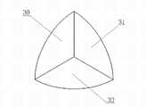
图3为本发明的光学角反射靶球其加工过程中形成1/8金属球体步骤的示意图;Fig. 3 is the schematic diagram that forms 1/8 metal sphere step in its processing process of optical angle reflective target ball of the present invention;
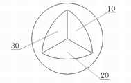
图4为本发明的光学角反射靶球的结构示意图;Fig. 4 is the structural representation of the optical angle reflection target ball of the present invention;
图5为本发明的光学角反射靶球的成品结构示意图。Fig. 5 is a schematic diagram of the finished structure of the optical angle reflective target ball of the present invention.
具体实施方式Detailed ways
下面结合附图详细说明本发明的具体实施方式。Specific embodiments of the present invention will be described in detail below in conjunction with the accompanying drawings.
下面就本发明的光学角反射靶球其一种加工方法进行介绍,该方法的具体步骤如下。首先取一实心金属球体,对其依次进行三次对半切割,分别得到一个1/2金属球体(如图1所示)、一个1/4金属球体(如图2所示)和两个1/8金属球体(如图3所示),舍去一个1/8球体。如图1、2、3所示,在所述1/2金属球体、1/4金属球体、1/8金属球体中,形成了三个反射面10、20、30;还形成了三组对应的结合面:结合面11与结合面21;结合面12与结合面31;结合面22与结合面32。下面,在每组对应的结合面的两个面的其中之一上挖槽并涂上焊料,以备焊接对应的结合面,图示实施例中为在结合面11、12、22上挖槽、涂焊料。并且,对反射面10、20、30进行抛光镀膜,以提高其反射率。接下来,将每组对应的结合面进行焊接,即将结合面11与结合面21焊接,将结合面12与结合面31焊接,将结合面22与结合面32焊接,形成如图4的7/8球体,即光学角反射靶球,其中形成了相互垂直的三个反射面10、20、30。最后,在光学角反射靶球51的反射面10、20、30的上方加上遮光保护圈52,形成如图5的结构,即为成品。A processing method of the optical angle reflective target ball of the present invention is introduced below, and the specific steps of the method are as follows. First, take a solid metal sphere, cut it in half three times in sequence, and obtain a 1/2 metal sphere (as shown in Figure 1), a 1/4 metal sphere (as shown in Figure 2) and two 1/2 metal spheres respectively. 8 metal spheres (as shown in Figure 3), one 1/8 sphere is discarded. As shown in Figures 1, 2, and 3, in the 1/2 metal sphere, 1/4 metal sphere, and 1/8 metal sphere, three
如图4所示,本发明的光学角反射靶球是一个7/8球体,在所缺的1/8球体位置处形成了相互垂直的三个反射面10、20、30。该球体为全金属结构。反射面10、20、30为抛光镀膜表面。该光学角反射靶球可以由一个1/2金属球体、一个1/4金属球体和一个1/8金属球体固定结合而形成,所述的1/2、1/4、1/8金属球体为从同一个实心金属球体上切割而成。所述固定结合可以采用多种方式,如焊接(在上面的加工方法中已经描述)、粘接,甚或是浇铸、挤压成形之类的一体成型。As shown in FIG. 4 , the optical angle reflective target ball of the present invention is a 7/8 sphere, and three mutually perpendicular
以上仅是本发明的具体应用范例,对本发明的保护范围不构成任何限制。凡采用等同变换或者等效替换而形成的技术方案,均落在本发明权利保护范围之内。The above are only specific application examples of the present invention, and do not constitute any limitation to the protection scope of the present invention. All technical solutions formed by equivalent transformation or equivalent replacement fall within the protection scope of the present invention.
Claims (8)
Translated fromChinesePriority Applications (1)
| Application Number | Priority Date | Filing Date | Title |
|---|---|---|---|
| CN201310112067XACN103207422A (en) | 2013-04-02 | 2013-04-02 | Optical angle reflection target ball and manufacturing method thereof |
Applications Claiming Priority (1)
| Application Number | Priority Date | Filing Date | Title |
|---|---|---|---|
| CN201310112067XACN103207422A (en) | 2013-04-02 | 2013-04-02 | Optical angle reflection target ball and manufacturing method thereof |
Publications (1)
| Publication Number | Publication Date |
|---|---|
| CN103207422Atrue CN103207422A (en) | 2013-07-17 |
Family
ID=48754697
Family Applications (1)
| Application Number | Title | Priority Date | Filing Date |
|---|---|---|---|
| CN201310112067XAPendingCN103207422A (en) | 2013-04-02 | 2013-04-02 | Optical angle reflection target ball and manufacturing method thereof |
Country Status (1)
| Country | Link |
|---|---|
| CN (1) | CN103207422A (en) |
Cited By (4)
| Publication number | Priority date | Publication date | Assignee | Title |
|---|---|---|---|---|
| CN105929531A (en)* | 2016-07-12 | 2016-09-07 | 武汉大学 | A Numerical Simulation Method of Far Field Diffraction Intensity of Laser Corner Reflector |
| CN106094889A (en)* | 2016-07-27 | 2016-11-09 | 中国电子科技集团公司第三十八研究所 | A kind of laser-bounce target ball actively self-adaptive regulating |
| CN108802877A (en)* | 2018-06-08 | 2018-11-13 | 四川拉姆达科技有限公司 | A kind of integral type all-metal reflection target ball |
| CN119087370A (en)* | 2024-09-09 | 2024-12-06 | 北京航空航天大学 | A passive polarization calibration body for full polarization measurement radar system calibration |
Citations (9)
| Publication number | Priority date | Publication date | Assignee | Title |
|---|---|---|---|---|
| DE2308701A1 (en)* | 1973-02-22 | 1974-09-05 | Hagenuk Neufeldt Kuhnke Gmbh | RADAR REFLECTOR CONSISTING OF SEVERAL TRIPLE MIRRORS |
| US4740056A (en)* | 1986-04-24 | 1988-04-26 | Bennett John G | Collapsible corner reflector |
| US4785301A (en)* | 1985-12-19 | 1988-11-15 | Marlene Schafer | Method for producing a radar reflector |
| CN2450734Y (en)* | 2000-11-02 | 2001-09-26 | 程晔增 | Magnetic combined globe |
| US20040212886A1 (en)* | 2003-01-30 | 2004-10-28 | Hubbs William O. | Displacement process for hollow surveying retroreflector |
| US7110194B2 (en)* | 2002-11-27 | 2006-09-19 | Hubbs Machine & Manufacturing Inc. | Spherical retro-reflector mount negative |
| CN1922511A (en)* | 2004-02-24 | 2007-02-28 | Faro科技有限公司 | Retroreflector covered by window |
| CN102753989A (en)* | 2009-09-21 | 2012-10-24 | 法罗技术股份有限公司 | Laser pointing mechanism |
| CN203178509U (en)* | 2013-04-02 | 2013-09-04 | 中国科学院光电研究院 | Optical angle reflective target ball |
- 2013
- 2013-04-02CNCN201310112067XApatent/CN103207422A/enactivePending
Patent Citations (9)
| Publication number | Priority date | Publication date | Assignee | Title |
|---|---|---|---|---|
| DE2308701A1 (en)* | 1973-02-22 | 1974-09-05 | Hagenuk Neufeldt Kuhnke Gmbh | RADAR REFLECTOR CONSISTING OF SEVERAL TRIPLE MIRRORS |
| US4785301A (en)* | 1985-12-19 | 1988-11-15 | Marlene Schafer | Method for producing a radar reflector |
| US4740056A (en)* | 1986-04-24 | 1988-04-26 | Bennett John G | Collapsible corner reflector |
| CN2450734Y (en)* | 2000-11-02 | 2001-09-26 | 程晔增 | Magnetic combined globe |
| US7110194B2 (en)* | 2002-11-27 | 2006-09-19 | Hubbs Machine & Manufacturing Inc. | Spherical retro-reflector mount negative |
| US20040212886A1 (en)* | 2003-01-30 | 2004-10-28 | Hubbs William O. | Displacement process for hollow surveying retroreflector |
| CN1922511A (en)* | 2004-02-24 | 2007-02-28 | Faro科技有限公司 | Retroreflector covered by window |
| CN102753989A (en)* | 2009-09-21 | 2012-10-24 | 法罗技术股份有限公司 | Laser pointing mechanism |
| CN203178509U (en)* | 2013-04-02 | 2013-09-04 | 中国科学院光电研究院 | Optical angle reflective target ball |
Cited By (6)
| Publication number | Priority date | Publication date | Assignee | Title |
|---|---|---|---|---|
| CN105929531A (en)* | 2016-07-12 | 2016-09-07 | 武汉大学 | A Numerical Simulation Method of Far Field Diffraction Intensity of Laser Corner Reflector |
| CN105929531B (en)* | 2016-07-12 | 2018-04-20 | 武汉大学 | A Numerical Simulation Method of Far Field Diffraction Intensity of Laser Corner Reflector |
| CN106094889A (en)* | 2016-07-27 | 2016-11-09 | 中国电子科技集团公司第三十八研究所 | A kind of laser-bounce target ball actively self-adaptive regulating |
| CN106094889B (en)* | 2016-07-27 | 2023-07-14 | 中国电子科技集团公司第三十八研究所 | Active self-adaptive adjustment device for laser reflective target ball |
| CN108802877A (en)* | 2018-06-08 | 2018-11-13 | 四川拉姆达科技有限公司 | A kind of integral type all-metal reflection target ball |
| CN119087370A (en)* | 2024-09-09 | 2024-12-06 | 北京航空航天大学 | A passive polarization calibration body for full polarization measurement radar system calibration |
Similar Documents
| Publication | Publication Date | Title |
|---|---|---|
| CN107782293B (en) | Spacecraft equipment posture information measurement method based on six degree of freedom laser tracking target | |
| CN106153074B (en) | Optical calibration system and method for inertial measurement combined dynamic navigation performance | |
| CN104483664B (en) | Single-linear-array laser radar equipment centering method | |
| CN109079774B (en) | A kind of isotropic visual sensing stereo spherical target and calibration method | |
| CN107782240A (en) | A kind of two dimensional laser scanning instrument scaling method, system and device | |
| CN103207422A (en) | Optical angle reflection target ball and manufacturing method thereof | |
| CN104142579A (en) | Adjustment method for reflectors of periscopic type acquisition and tracking mechanism | |
| CN107234487B (en) | Moving component multi-parameter detecting method based on combinatorial surface type standard | |
| CN106595638B (en) | Three-axis air bearing attitude measurement device and measurement method based on photoelectric tracking technology | |
| CN110440760B (en) | Preparation method of high-precision photogrammetry target | |
| CN103925890B (en) | Three-dimensional angle measuring system based on beam aberration | |
| CN104154931B (en) | Optical machine positioning survey method of intersection survey system | |
| CN203178509U (en) | Optical angle reflective target ball | |
| CN105629430B (en) | 360 degree of total reflection prisms and its aligning method | |
| CN113267195B (en) | A relative pose measurement method for docking assembly of spacecraft cabins | |
| CN106767403A (en) | A kind of optical axis position error detection method of many optical axis optical systems | |
| CN104807437B (en) | A kind of multi-pass self calibration laser tracking measurement system | |
| CN105953820B (en) | A kind of optical calibrating device of inertial measurement combination dynamic navigation performance | |
| CN110671400B (en) | Target ball assembling tool and method for laser tracker | |
| CN210859477U (en) | Laser tracker target ball assembly fixture | |
| CN105974502B (en) | Reflecting mirror in three-dimensional laser scanner and three-dimensional laser scanner | |
| CN108802877A (en) | A kind of integral type all-metal reflection target ball | |
| CN101866183B (en) | Coarse Tracking Boresight Calibration Device for Space Laser Communication System | |
| CN107747945B (en) | An attitude angle detection device for a suspended platform | |
| CN102004252B (en) | Device for carrying out three-dimensional space positioning on static workpieces and special hand-held movable optical retroreflector |
Legal Events
| Date | Code | Title | Description |
|---|---|---|---|
| C06 | Publication | ||
| PB01 | Publication | ||
| C10 | Entry into substantive examination | ||
| SE01 | Entry into force of request for substantive examination | ||
| C02 | Deemed withdrawal of patent application after publication (patent law 2001) | ||
| WD01 | Invention patent application deemed withdrawn after publication | Application publication date:20130717 |