CN103201920A - Power distribution device - Google Patents
Power distribution deviceDownload PDFInfo
- Publication number
- CN103201920A CN103201920ACN2011800502604ACN201180050260ACN103201920ACN 103201920 ACN103201920 ACN 103201920ACN 2011800502604 ACN2011800502604 ACN 2011800502604ACN 201180050260 ACN201180050260 ACN 201180050260ACN 103201920 ACN103201920 ACN 103201920A
- Authority
- CN
- China
- Prior art keywords
- power distribution
- current protection
- protection switch
- distribution equipment
- switch
- Prior art date
- Legal status (The legal status is an assumption and is not a legal conclusion. Google has not performed a legal analysis and makes no representation as to the accuracy of the status listed.)
- Pending
Links
Images


Classifications
- H—ELECTRICITY
- H02—GENERATION; CONVERSION OR DISTRIBUTION OF ELECTRIC POWER
- H02H—EMERGENCY PROTECTIVE CIRCUIT ARRANGEMENTS
- H02H3/00—Emergency protective circuit arrangements for automatic disconnection directly responsive to an undesired change from normal electric working condition with or without subsequent reconnection ; integrated protection
- H02H3/26—Emergency protective circuit arrangements for automatic disconnection directly responsive to an undesired change from normal electric working condition with or without subsequent reconnection ; integrated protection responsive to difference between voltages or between currents; responsive to phase angle between voltages or between currents
- H02H3/32—Emergency protective circuit arrangements for automatic disconnection directly responsive to an undesired change from normal electric working condition with or without subsequent reconnection ; integrated protection responsive to difference between voltages or between currents; responsive to phase angle between voltages or between currents involving comparison of the voltage or current values at corresponding points in different conductors of a single system, e.g. of currents in go and return conductors
- H02H3/33—Emergency protective circuit arrangements for automatic disconnection directly responsive to an undesired change from normal electric working condition with or without subsequent reconnection ; integrated protection responsive to difference between voltages or between currents; responsive to phase angle between voltages or between currents involving comparison of the voltage or current values at corresponding points in different conductors of a single system, e.g. of currents in go and return conductors using summation current transformers
- H02H3/334—Emergency protective circuit arrangements for automatic disconnection directly responsive to an undesired change from normal electric working condition with or without subsequent reconnection ; integrated protection responsive to difference between voltages or between currents; responsive to phase angle between voltages or between currents involving comparison of the voltage or current values at corresponding points in different conductors of a single system, e.g. of currents in go and return conductors using summation current transformers with means to produce an artificial imbalance for other protection or monitoring reasons or remote control
- H02H3/335—Emergency protective circuit arrangements for automatic disconnection directly responsive to an undesired change from normal electric working condition with or without subsequent reconnection ; integrated protection responsive to difference between voltages or between currents; responsive to phase angle between voltages or between currents involving comparison of the voltage or current values at corresponding points in different conductors of a single system, e.g. of currents in go and return conductors using summation current transformers with means to produce an artificial imbalance for other protection or monitoring reasons or remote control the main function being self testing of the device
- H—ELECTRICITY
- H01—ELECTRIC ELEMENTS
- H01H—ELECTRIC SWITCHES; RELAYS; SELECTORS; EMERGENCY PROTECTIVE DEVICES
- H01H71/00—Details of the protective switches or relays covered by groups H01H73/00 - H01H83/00
- H01H71/74—Means for adjusting the conditions under which the device will function to provide protection
- H—ELECTRICITY
- H01—ELECTRIC ELEMENTS
- H01H—ELECTRIC SWITCHES; RELAYS; SELECTORS; EMERGENCY PROTECTIVE DEVICES
- H01H83/00—Protective switches, e.g. circuit-breaking switches, or protective relays operated by abnormal electrical conditions otherwise than solely by excess current
- H01H83/02—Protective switches, e.g. circuit-breaking switches, or protective relays operated by abnormal electrical conditions otherwise than solely by excess current operated by earth fault currents
- H01H83/04—Protective switches, e.g. circuit-breaking switches, or protective relays operated by abnormal electrical conditions otherwise than solely by excess current operated by earth fault currents with testing means for indicating the ability of the switch or relay to function properly
- H—ELECTRICITY
- H02—GENERATION; CONVERSION OR DISTRIBUTION OF ELECTRIC POWER
- H02H—EMERGENCY PROTECTIVE CIRCUIT ARRANGEMENTS
- H02H3/00—Emergency protective circuit arrangements for automatic disconnection directly responsive to an undesired change from normal electric working condition with or without subsequent reconnection ; integrated protection
- H02H3/02—Details
- H02H3/027—Details with automatic disconnection after a predetermined time
- H—ELECTRICITY
- H02—GENERATION; CONVERSION OR DISTRIBUTION OF ELECTRIC POWER
- H02H—EMERGENCY PROTECTIVE CIRCUIT ARRANGEMENTS
- H02H3/00—Emergency protective circuit arrangements for automatic disconnection directly responsive to an undesired change from normal electric working condition with or without subsequent reconnection ; integrated protection
- H02H3/02—Details
- H02H3/04—Details with warning or supervision in addition to disconnection, e.g. for indicating that protective apparatus has functioned
- H02H3/044—Checking correct functioning of protective arrangements, e.g. by simulating a fault
- H—ELECTRICITY
- H02—GENERATION; CONVERSION OR DISTRIBUTION OF ELECTRIC POWER
- H02H—EMERGENCY PROTECTIVE CIRCUIT ARRANGEMENTS
- H02H3/00—Emergency protective circuit arrangements for automatic disconnection directly responsive to an undesired change from normal electric working condition with or without subsequent reconnection ; integrated protection
- H02H3/02—Details
- H02H3/05—Details with means for increasing reliability, e.g. redundancy arrangements
- H—ELECTRICITY
- H02—GENERATION; CONVERSION OR DISTRIBUTION OF ELECTRIC POWER
- H02H—EMERGENCY PROTECTIVE CIRCUIT ARRANGEMENTS
- H02H3/00—Emergency protective circuit arrangements for automatic disconnection directly responsive to an undesired change from normal electric working condition with or without subsequent reconnection ; integrated protection
- H02H3/08—Emergency protective circuit arrangements for automatic disconnection directly responsive to an undesired change from normal electric working condition with or without subsequent reconnection ; integrated protection responsive to excess current
- H02H3/093—Emergency protective circuit arrangements for automatic disconnection directly responsive to an undesired change from normal electric working condition with or without subsequent reconnection ; integrated protection responsive to excess current with timing means
Landscapes
- Engineering & Computer Science (AREA)
- Power Engineering (AREA)
- Emergency Protection Circuit Devices (AREA)
- Keying Circuit Devices (AREA)
- Remote Monitoring And Control Of Power-Distribution Networks (AREA)
- Supply And Distribution Of Alternating Current (AREA)
Abstract
Description
Translated fromChinese技术领域technical field
本发明涉及一种根据权利要求1的前序部分所述的配电装置/开关设备。The invention relates to a switchgear/switchgear according to the preamble of
背景技术Background technique
故障电流保护开关具有检查装置,以便检查相关的故障电流保护开关的功能,并进而检查在出现故障电流时的脱扣/释放。因为在此时相关的故障电流保护开关被脱扣,所以在下游连接的子网络被断电,并进而所有连接的电器被断电。这使得大多数电设备使用者感觉到不舒适,因为在许多设备中删除了有针对性的设定。此外存在大量电设备,其中断电可能导致严重的问题,因为例如相关的电设备履行安全任务或者执行控制过程,并因此相关设备的断电会导致问题。The fault current circuit breaker has a checking device in order to check the function of the associated fault current circuit breaker and thus to check the tripping/release in the event of a fault current. Since at this moment the associated fault current circuit breaker is tripped, the downstream connected sub-network is de-energized and thus all connected electrical appliances are de-energized. This makes most electric device users feel uncomfortable, because targeted settings are removed in many devices. Furthermore, there are a large number of electrical installations in which a power outage can lead to serious problems, because for example the relevant electrical equipment fulfills a safety task or executes a control process, and thus a de-energization of the relevant equipment can cause problems.
发明内容Contents of the invention
因此,本发明的目的在于,提出一种前述类型的配电装置,利用该配电装置可以避免上述缺点,且利用该配电装置支持在无强制网络断电的情况下进行故障电流保护开关的功能检查。It is therefore the object of the present invention to propose a power distribution device of the aforementioned type, with which the above-mentioned disadvantages are avoided and with which fault current protection switching without forced network outages is supported. Functional check.
根据本发明该目的通过权利要求1所述的特征实现。This object is achieved according to the invention by the features of
通过这种配电装置可以同时接通两个故障电流保护开关,负载电流从两个故障电流保护开关中的一个切换至另一个故障电流保护开关,同时不出现两个故障电流保护开关之一的脱扣并因此不出现网络断电。由此能够在不会因此而失去对电器的设定或者由于重要设备断电而出现安全危险的情况下执行对故障电流保护开关的功能检查。由此可以更换识别为故障的故障电流保护开关,而同时不必为此将连接在故障电流保护开关下游的分电网断电。Through this power distribution device, two fault current protection switches can be connected at the same time, and the load current is switched from one of the two fault current protection switches to the other fault current protection switch, and at the same time, one of the two fault current protection switches does not appear trip and therefore no network outage. A function check of the fault current circuit breaker can thus be carried out without losing the setting of the electrical appliance or causing a safety hazard due to a power outage of important installations. As a result, a faulty circuit breaker detected as faulty can be replaced without at the same time having to de-energize the power distribution network connected downstream of the fault circuit breaker.
如权利要求1那样同时形成说明书的一部分的从属权利要求2至10涉及本发明的其它有利的设计方案。Dependent claims 2 to 10 , which form part of the description at the same time as
本发明还涉及根据权利要求11的前序部分所述的故障电流保护开关。The invention also relates to a fault current protective switch according to the preamble of
在负载电流从一个故障电流保护开关切换至另一个故障电流保护开关的切换过程中,不排除在这两个故障电流保护开关的至少一个上暂时会出现不对称的电势。然而,这种电势差在故障电流保护开关上会如出现故障电流那样起作用,并因此意外地且在不出现故障电流的情况下使故障电流保护开关脱扣。然而,由此可能会阻止从一个故障电流保护开关至另一个故障电流保护开关的无中断切换。During the switching of the load current from one fault current circuit breaker to the other fault current circuit breaker, it cannot be ruled out that an asymmetrical potential temporarily occurs across at least one of the two fault current circuit breaker switches. However, this potential difference can act on the fault current switch as if a fault current had occurred and thus trip the fault current switch accidentally and without the occurrence of a fault current. However, this may prevent an uninterrupted switching from one fault current circuit breaker to the other fault current circuit breaker.
因此本发明的目的在于,给出一种前述类型的故障电流保护开关,利用该故障电流保护开关可以避免所述缺点并且利用该故障电流保护开关有利于在不强制网络断电的情况下对故障电流保护开关进行功能检查。It is therefore the object of the present invention to provide a fault current protective switch of the aforementioned type, with which the disadvantages mentioned can be avoided and with which it is advantageous to detect faults without forcing the network to be de-energized. Check the function of the current protection switch.
根据本发明这通过权利要求11所述的特征实现。This is achieved according to the invention by the features of
由此在负载电流从第一故障电流保护开关至第二故障电流保护开关的无间断切换过程期间,可以阻止这两个故障电流保护开关之一被无意地脱扣。由此可以在切换过程期间阻止错误脱扣。由此可以阻止在故障电流保护开关的功能检查期间意外的网络断电。During the uninterrupted switching process of the load current from the first fault current circuit breaker to the second fault current circuit breaker, unintentional tripping of one of the two fault current circuit breaker switches can thus be prevented. False tripping can thus be prevented during the switching process. Unintentional network interruptions during the function check of the fault current circuit breaker can thus be prevented.
如权利要求10那样同时形成说明书的一部分的从属权利要求12涉及本发明的其它有利的设计方案。Dependent claim 12 , which also forms part of the description like
本发明还涉及根据权利要求13的前序部分所述的用于故障电流保护开关的无中断功能检查的方法。The invention also relates to a method for the non-stop function checking of a fault current circuit breaker according to the preamble of
如上所述,在对故障电流保护开关进行功能检查时由于网络断电而出现问题,该问题至少是功能检查的间接后果。As mentioned above, problems arising from network outages during the function check of the fault current circuit breaker are at least an indirect consequence of the function check.
因此,本发明的目的在于给出前述类型的方法,借助于该方法可以避免所述缺点并且利用该方法有利于在不强制网络断电的情况下对故障电流保护开关进行功能检查。It is therefore the object of the present invention to provide a method of the aforementioned type by means of which the disadvantages mentioned can be avoided and with which a function check of a fault current circuit breaker can be facilitated without forcing a network shutdown.
根据本发明该目的通过权利要求13所述的特征实现。This object is achieved according to the invention by the features of
由此能在不出现网络断电的情况下对故障电流保护开关进行功能检查。由此能够在不会因此而失去对电器的设定或者由于重要设备断电而出现安全危险的情况下执行对故障电流保护开关的功能检查In this way, a function check of the fault current circuit breaker can be carried out without the occurrence of a network outage. This makes it possible to carry out a function check of the fault current circuit breaker without losing the setting of the appliance or causing a safety hazard due to a power outage of important equipment
如权利要求13那样同时形成说明书的一部分的从属权利要求14至17涉及本发明的其它有利的设计方案。Dependent claims 14 to 17 , which form part of the description at the same time as
附图说明Description of drawings
下面参考其中仅示例性示出优选实施方案的附图进一步描述本发明。附图中:The invention is further described below with reference to the accompanying drawings, in which only preferred embodiments are shown by way of example. In the attached picture:
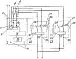
图1是根据本发明的配电装置和两个故障电流保护开关的系统的第一优选实施方案的框图,Figure 1 is a block diagram of a first preferred embodiment of a system of a power distribution device and two fault current protection switches according to the invention,
图2是根据本发明的配电装置和两个故障电流保护开关的系统的第二优选实施方案的框图,Figure 2 is a block diagram of a second preferred embodiment of a system of a power distribution device and two fault current protection switches according to the invention,
图3是根据本发明的配电装置和两个故障电流保护开关的系统的第三优选实施方案的框图,Figure 3 is a block diagram of a third preferred embodiment of a system of a power distribution device and two fault current protection switches according to the invention,
图4以并联地透视法示出根据本发明的配电装置、两个故障电流保护开关和联接装置的系统的第一结构设计方案,FIG. 4 shows a first structural configuration of a system of a power distribution device, two fault current protection switches and a coupling device according to the invention in a parallel perspective,
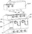
图5以并联地透视法的第一视角示出根据本发明的配电装置、两个故障电流保护开关和联接装置的系统的第二结构设计方案,以及FIG. 5 shows a second structural configuration of a system of a power distribution device, two fault current protection switches and a coupling device according to the invention in a first view of parallel ground perspective, and
图6以并联地透视法的第二视角示出根据本发明的配电装置、两个故障电流保护开关和联接装置的系统的第二结构设计方案。FIG. 6 shows a second structural configuration of a system according to the invention of a power distribution device, two fault current circuit breakers and a coupling device in a second view of parallel perspective.
具体实施方式Detailed ways
图1至6分别示出由第一故障电流保护开关22、第二故障电流保护开关23以及根据本发明的配电装置1组成的系统,其中第一故障电流保护开关22和第二故障电流保护开关23借助于联接单元在电路技术方面彼此并联地与配电装置1联接。1 to 6 respectively show a system composed of a first fault
本发明涉及一种用于对至少一个第一故障电流保护开关22进行无中断的功能检查的方法,并且涉及用于有利地执行所述方法的装置。下面描述相关装置的优选实施方案,其中如下描述的根据本发明的方法优选不必与所述装置的应用联系在一起。The invention relates to a method for an uninterrupted function check of at least one first fault
所述的装置包括根据本发明的优选实施方案的故障电流保护开关22、23、专门的根据本发明的配电装置1以及联接装置12,该联接装置用于将两个故障电流保护开关与配电装置至少在电路技术方面并进而尤其是机械地连接。Said arrangement comprises a fault
此外,图1至3分别示出一电路框图,其中分别示出带有至少一个第一电配电装置输入件2、至少一个第一电配电装置输出件3和至少一个第二电配电装置输出件4的配电装置1的不同的优选实施方案,其中在配电装置1的第一工作状态中第一配电装置输入件2与第一配电装置输出件3在电路技术方面连接,在配电装置1的第二工作状态中第一配电装置输入件2与第二配电装置输出件4在电路技术方面连接,其中配电装置1设计用于无中断地从第一工作状态过渡至第二工作状态和/或无中断地从第二工作状态过渡至第一工作状态。Furthermore, FIGS. 1 to 3 each show a block circuit diagram in which each shows a circuit with at least one first electrical
通过这种配电装置1可以使两个故障电流保护开关22、23并联,并将负载电流从这两个故障电流保护开关22、23中的一个切换至另一个故障电流保护开关23、22,而不会在此时引起这两个故障电流保护开关22、23之一被脱扣且因此不导致网络断电。由此,可以在不失去对电器的设定或者由于对重要电器的非计划断电而导致安全性危险的情况下,对故障电流保护开关22、23执行功能检查。由此也可以更换被识别为损坏的故障电流保护开关22,而同时不必为此使连接在故障电流保护开关22、23下游的分电网断电,这是因为在替换过程的持续时间期间相应的另一故障电流保护开关23保护了连接在下游的电网以及所连接的负载。With such a
术语“无中断”优选表示负载电流从一个配电装置——在此例如从第一故障电流保护开关22——切换至另一个配电装置——在此例如至第二故障电流保护开关23,而同时不因此出现连接在下游的部件的供电过程的中断,这样的中断由于在切换过程本身期间短时的网络中断或者由于故障电流保护开关22、23的至少一个的不期望的脱扣引起。The term "uninterrupted" preferably means that the load current is switched from one power distribution device, here for example from the first fault current
根据本发明,配电装置1可以具有第一工作状态和第二工作状态。配电装置1优选仅具有这两个稳定的工作状态,且从所述工作状态中的一个至相应的另一个的过渡设计为短时的切换过程,该切换过程本身并不设置为稳定的工作状态。According to the present invention, the
在本发明的一改进方案中,配电装置1还可以具有第三工作状态,在该第三工作状态中第一配电装置输入件2与第一配电装置输出件3在电路技术方面连接并且与第二配电装置输出件4在电路技术方面连接,从第一或第二工作状态至第三工作状态的过渡以及从第三工作状态至第一或第二工作状态的过渡同样设计为无中断的。由此不仅实现了负载电流从第一故障电流保护开关22至第二故障电流保护开关23的无中断的切换或相反的切换,而且实现了这两个故障电流保护开关22、23的稳定的并行工作。In a further development of the invention, the
像已经设想的那样,配电装置1具有至少一个第一电配电装置输入件2、至少一个第一电配电装置输出件3和至少一个第二电配电装置输出件4。术语“输入件”以及“输出件”优选应当被解释为:相应地以单独使用的术语优选包括输入件或输出件2、3、4的所有功能上所需的连接件。在示出的优选的实施方案中,第一配电装置输入件2包括两个连接件,第一和第二配电装置输出件3、4同样分别包括两个连接件。配电装置输入件2优选具有与每个配电装置输出件3、4相同数量的连接件,以及与待保护或者说待切换的电网相同数量的导体、进而相同数量的相位和中性导体(零线)。As already conceived, the
配电装置1优选具有至少一个开关5、7,该开关在电路技术方面与第一控制装置输入件2、第一控制装置输出件3和第二控制装置输出件4连接,其中在开关5、7的第一开关位置中第一控制装置输入件2在电路技术方面与第一控制装置输出件3连接,而在开关5、7的第二开关位置中第一控制装置输入件3在电路技术方面与第二控制装置输出件4连接。相关的开关5、7如此设计,即从第一开关位置至第二开关位置的过渡无中断地进行。在此可以设计为,开关5、7仅具有两个所述的稳定的开关状态。此外——在具有前述第三工作状态的配电装置1的设计中——也设置有相应的第三开关位置,例如该第三开关位置作为开关5、7的中间位置实现。The
根据在图1和2中示出的实施方案,配电装置1优选具有至少一个机械的开关5,该开关具有至少局部搭接的开关触点6。在相关的附图中,这些通过对机械的开关5的象征性图示表示。借助于这种机械的开关5可以形成对电干扰不敏感的配电装置1,其即使在困难的条件下也能被简单地维护。According to the embodiment shown in FIGS. 1 and 2 , the
机械的开关5的触点优选借助于一开关轴连接和引导。此外,机械的开关5优选与一开关锁连接。由此可以预先规定并强制控制相关的机械开关5的开关过程。The contacts of the
根据图3示出的实施方案,配电装置1优选具有至少一个电子开关7。由此可以形成在很大程度上对机械振动不敏感且实现快速切换过程的配电装置1。相关的电子开关7优选设计为包括可预定的多个三端双向交流开关/双向晶闸管(Triac)8的开关系统,如在图3中示出的那样。三端双向交流开关8表示“triode alternating current switch”。然而,也可以设想包括任意类型的作为开关起作用的开关系统的设计方案,该开关系统包括半导体,其中尤其是开关元件是或包括晶体管。According to the embodiment shown in FIG. 3 , the
配电装置1优选具有至少一个控制单元9用于控制从一个工作状态至另一个工作状态的过渡。通过这种控制单元9可以主动地执行和监控切换过程。由此例如可以监控:在第一故障电流保护开关22断电、因此在输入侧与网络分开之前,在第二故障电流保护开关23上便已经存在完全的网络电压。The
控制单元9优选设计为或包括可编程的逻辑电路和/或微处理器。此外,配电装置1优选具有用于给控制单元9提供能量的网络部分,然而其在附图中未示出。The
按照根据本发明的配电装置1的所示优选实施方案,该配电装置总共具有一个控制单元9,由控制单元9控制机械的或电子的开关5、7并与之作用连接。因此,例如控制单元9至少间接地——优选通过机电执行器——作用于开关锁;或者当开关5、7设计为电子开关7时例如控制所示三端双向交流开关的栅极连接件。也可以设计为,机械的开关5是布置在配电装置1中的继电器的一部分,该继电器由控制单元控制。According to the shown preferred embodiment of the
根据另一示出的优选实施方案,配电装置1包括至少一个电压测量装置用于测量在第一配电装置输出件3和/或第二配电装置输出件4上的电压。由此可以确保:在第一故障电流保护开关22断电之前便在第二故障电流保护开关23上存在完全的网络电压。在这种情况下,电压测量装置优选形成控制单元9的一部分,且控制单元9在电路技术方面与第一配电装置输出件3和/或第二配电装置输出件4连接。According to a further illustrated preferred embodiment, the
配电装置1优选还具有至少一个操纵元件25,该操纵元件25优选——在设有该操纵元件的情况下——与控制单元9作用连接,例如在简单设计的配电装置1中可以规定,操纵元件25例如设计成作为机械开关5的开关5的操作元件。优选如图所示地,操纵元件25与控制单元9相连接且作用于该控制单元。The
此外,按照根据本发明的配电装置1的一优选实施方案,配电装置1具有至少一个——尤其是光学的——信号单元11,该信号单元尤其由控制单元9控制。由此可以指示出配电装置1和/或与配电装置连接的故障电流保护开关22、23的工作状态。由此可以对使用者开通或给出任务以操纵两个故障电流保护开关22、23之一的检查设备。在所示实施方案中,配电装置1具有两个设计为LED的信号单元11。要指出,在图1至3中未示出在控制单元9与信号单元11之间的电路技术方面的连接。Furthermore, according to a preferred embodiment of the
图1示出由根据本发明的配电装置1、第一和第二故障电流保护开关22、23组成的第一优选实施方案。未示出的能量供给网络连接在第一电配电装置输入件2上。第一故障电流保护开关22的输入件在电路技术方面与第一配电装置输出件3连接,而第二故障电流保护开关23的输入件在电路技术方面与第二配电装置输出件4连接。Fig. 1 shows a first preferred embodiment consisting of a
配电装置1具有机械的开关5,该开关由控制单元9控制。The
第一和第二故障电流保护开关22、23根据图1设计为与网络电压无关的故障电流保护开关,所述故障电流保护开关分别具有总变流器32、永磁体脱扣器31以及脱扣电路或脱扣电流回路19和开关锁26,该开关锁控制分离触点20布置在其上的开关轴。在图1至3中未示出脱扣电流回路19的细节、因而未示出该脱扣电流回路19的所有部件或组件。此外,这两个故障电流保护开关22、23分别具有检查电路30,该检查电路具有检查键27和检查电阻28。当检查键27的触点闭合时,检查电路在总变流器32外部跨接地(vorbei)连接待保护的且通过故障电流保护开关22、23引导的网络的两个导体,并如此模拟故障电流。然而在此也可以规定与所示方案不同的其它实施方案。The first and second fault current protection switches 22, 23 are designed as network voltage-independent fault current protection switches according to FIG. A circuit or trip
图1所示的两个故障电流保护开关22、23优选配备有延迟的故障电流脱扣。在出现故障电流时,这种故障电流保护开关22、23不立即脱扣,而是仅当在一确定的时间之后仍存在故障电流时才脱扣。这种故障电流保护开关22、23也称为G类型或S类型。The two fault current
在根据图1的这种系统中,如果切换过程在比这两个故障电流保护开关22、23的脱扣延迟的持续时间更短的持续时间内进行,便实现了负载电流从第一至第二故障电流保护开关22、23的无中断切换,其中不引起脱扣。在切换过程期间出现的不对称的电势不会被误解为故障电流,这是因为该电势仅在其中不出现故障电流脱扣的极短的时间段内出现。In such a system according to FIG. 1, a load current change from the first to the second 2. Uninterrupted switching of the fault current protection switches 22, 23, which does not cause tripping. An asymmetrical potential that occurs during the switching process cannot be misinterpreted as a fault current, since this potential occurs only during a very short time period in which no fault current tripping occurs.
图2和3示出根据本发明的系统的其它实施方案。2 and 3 show other embodiments of the system according to the invention.
根据图2的系统的基本结构在很大程度上与根据图1的结构相同,其中根据图2的系统具有附加的组件。The basic structure of the system according to FIG. 2 is largely the same as the structure according to FIG. 1 , the system according to FIG. 2 having additional components.
根据图2的这两个故障电流保护开关22、23——从图2本身不能直接得到——设计为不具有脱扣延迟或非延迟式或无延迟式的,因此在识别出故障电流时尽可能快地脱扣。为了针对这种故障电流保护开关22、23也实现无中断的切换,优选配电装置1具有至少一个第一控制输出件10,从而以可预定的方式影响故障电流保护开关22、23的脱扣特性。The two fault current
根据图2的第一和第二故障电流保护开关22、23的脱扣电流回路19还分别具有第一电路布置21,从而使脱扣电流回路19的脱扣时间延长一可预定的时间段。根据脱扣回路的设计,所述的第一电路布置21可以设计为不同的。在此处的例子中,例如设计为,第一电路布置21设计用于使总变流器32的次级绕组与永磁体脱扣器31之间的连接短路。然而也可以规定其它的作用机制和电路布置。The tripping
根据故障电流保护开关22、23所示实施方案,另外优选规定,故障电流保护开关22、23具有至少一个第一控制输入件24用于控制第一电路布置21。According to the illustrated embodiment of the fault
可以规定对第一电路布置21的任意方式的控制,例如由根据本发明的配电装置1单独进行的控制,其中优选配电装置1具有至少一个第一控制输出件10,从而以可预定的方式影响故障电流保护开关22、23的脱扣特性,故障电流保护开关22、23优选与控制单元9在电路技术方面连接。Any desired control of the
像图2中示出的那样,配电装置1具有第一控制输出件10和第二控制输出件,其中第一控制输出件10在电路技术方面与第一故障电流保护开关22的第一控制输入件24连接,而第二控制输出件与第二故障电流保护开关23的第一控制输入件24连接。图6以分解图示出这种系统的立体的设计。As shown in FIG. 2 , the
也可以规定,故障电流保护开关22、23的其中一个设计为具有延迟的故障电流脱扣的故障电流保护开关,而另一个故障电流保护开关22、23设计为根据本发明的非延迟的故障电流保护开关22、23。It can also be provided that one of the fault
图3示出根据本发明的配电装置1和两个故障电流保护开关22、23的系统的第三优选实施方案,其中这两个故障电流保护开关22、23设计为具有延迟的故障电流脱扣的故障电流保护开关,其中配电装置1的开关设计为电子开关7并包括四个三端双向交流开关,这四个三端双向交流开关分别由控制单元9控制。FIG. 3 shows a third preferred embodiment of a system according to the invention of a
优选地,配电装置1以及故障电流保护开关22、23具有绝缘材料壳体。Preferably, the
可以规定,这两个故障电流保护开关22、23和配电装置1例如借助于滑线电桥/跨接线/跳线在电路技术方面连接。因为这样花费大且容易出错,所以尤其优选地提出:相关的部件借助于用于配电装置的联接装置12连接。这种用于配电装置1的联接装置12例如在图4至6中示出,其中示出根据本发明的系统的优选实施方案。It can be provided that the two fault
用于配电装置的优选的联接装置12具有至少一个第一输入件13和至少一个第一输出件14,其中第一输入件13和第一输出件14在电路技术方面连接,其中联接装置12具有至少一个第二输入件15和至少一个第二输出件16,其中第二输入件15和第二输出件16在电路技术方面连接,其中联接装置12具有至少一个第三输入件17和至少一个第三输出件18,其中第三输入件17和第三输出件18在电路技术方面连接。A
优选还提出,所述至少一个第一输入件13包括至少一个螺旋接线夹,和/或所述至少一个第二和/或第三输入件15、17和/或所述至少一个第一和/或第二和/或第三输出件14、16、18设计为插接触点。It is also preferably provided that the at least one
根据图5和6的联接装置12的实施方案以前述的优选方式设计,其中相关的实施方案还具有相应的触点和连接导线,以便连接配电装置1的第一控制输出件与第一和第二故障电流保护开关22、23的相应的(第一控制输入件)24。The embodiment of the
根据图4的系统具有与本发明的此前描述的结构上的设计方案不同的结构。该系统不具有配电装置,而仅具有控制器40。这种控制器40优选按照根据本发明的配电装置1的优选实施方案设计,其中控制器40本身不具有开关,而仅具有用于控制外部开关必需的电端口。The system according to FIG. 4 has a different structure than the previously described structural design of the invention. This system does not have a power distribution device, but only a
根据图4的系统还具有专门设计的联接/开关单元41,该联接/开关单元41包括开关。该联接/开关单元41具有用于电能供给网络的导线的相应的馈电线以及用于控制第一或第二故障电流保护开关22、23的相应的输出件。该联接/开关单元41还包括另一开关,该开关是按照在根据本发明的配电装置1中的开关的前述实施方案设计的并因此实现了负载电流从两个故障电流保护开关中的一个至另一个的无中断的切换。此外,该联接/开关单元41还包括用于接收由控制器40执行的开关任务的端口。The system according to FIG. 4 also has a specially designed coupling/switching unit 41 which includes a switch. The coupling/switching unit 41 has corresponding feeders for the conductors of the power supply network and corresponding outputs for controlling the first or second fault
本发明还涉及一种用于对第一故障电流保护开关22进行无中断功能检查的方法,其中负载电流被引导经过第一故障电流保护开关22,其中第二故障电流保护开关23在输入侧与第一故障电流保护开关22并联地连接到负载电流,其中负载电流无中断地从第一故障电流保护开关22切换至第二故障电流保护开关23,其中执行对第一故障电流保护开关22的功能检查,其中在成功地执行第一故障电流保护开关22的功能检查之后接通第一故障电流保护开关22,其中第一故障电流保护开关22在输入侧与第二故障电流保护开关23并联地连接到负载电流,其中负载电流无中断地从第二故障电流保护开关23切换至第一故障电流保护开关22,并且其中第二故障电流保护开关23被切断。The invention also relates to a method for an uninterrupted function check of a first fault
利用这种方法可以无中断地测试一个故障电流保护开关22、23的功能。In this way, the function of a fault
下面描述根据本发明的方法的特别优选的实施方案的流程,其中并非所有被描述的优选方法步骤都必须执行。The sequence of a particularly preferred embodiment of the method according to the invention is described below, in which not all described preferred method steps have to be carried out.
负载电流流过配电装置1——且优选在此前通过联接装置12——以及通过第一故障电流保护开关22并流至负载。在电路技术方面与第一故障电流保护开关22并联地布置第二故障电流保护开关23,其中第二故障电流保护开关23在此时刻以分离触头20闭合的方式被接通,然而在输入侧不与能量供给网络连接。因此在此时刻没有负载电流经第二故障电流保护开关23流至负载。The load current flows through the
然而第二故障电流保护开关23在输出侧或负载侧与第一故障电流保护开关22的相应的连接件连接,因此其检查装置中也存在基本上与第一故障电流保护开关22的相应的设备一样的电势。在根据本发明的方法的优选实施方案中,在进一步检查第一故障电流保护开关22的故障电流脱扣的功能之前执行第二故障电流保护开关23的相应的功能检查,优选通过相应地操纵第二故障电流保护开关23的检查键27来进行。However, the second fault
为了无中断地检查,第二故障电流保护开关23借助于配电装置1在输入侧与第一故障电流保护开关22并联地连接在能量供给网络上。在这种状态下,负载电流既经过第一故障电流保护开关22也经过第二故障电流保护开关23流至负载,如果在该时刻所述负载工作便是如此。For uninterrupted checking, a second fault
优选地,在从第一故障电流保护开关22至第二故障电流保护开关23的无中断地切换之前检查:第二故障电流保护开关23是否接通。由此,如果第二故障电流保护开关23仍不引导负载电流,可以阻止第一故障电流保护开关22的切断。Preferably, prior to the uninterrupted switching from the first fault
必要时可以规定,阻拦第一和第二故障电流保护开关22、23的脱扣电流回路19或者在从第一故障电流保护开关22至第二故障电流保护开关23的无中断的切换期间在一可预定的时间段中以可预定方式延长第一故障电流保护开关22的第一脱扣时间和第二故障电流保护开关23的第二脱扣时间。在此,完全禁止脱扣也可以体现为脱扣时间的延长。Optionally, it can be provided that the tripping
随后负载电流无中断地从第一故障电流保护开关切换至第二故障电流保护开关,然后第一故障电流保护开关22与负载电流分离,其中该切换过程优选利用根据本发明的配电装置执行。第一故障电流保护开关22像之前一样在负载侧上与第二故障电流保护开关23连接。The load current is then switched without interruption from the first fault current circuit breaker to the second fault current circuit breaker, and then the first fault
如果已经对第一和第二故障电流保护开关22、23的脱扣电流回路进行了阻拦,则取消该阻拦。If the tripping current circuit of the first and second fault
优选地,此后对于从第一故障电流保护开关22至第二故障电流保护开关23的无中断的切断输出尤其是光学的第一信号。由此使使用者得知,可以对第一故障电流保护开关22的故障电流脱扣功能进行检查。优选地,以这种方式通知使用者其它的工作状态或给使用者例如关于对确定的故障电流保护开关的检查设备进行操作的指示。Preferably, a first, in particular optical, signal is then output for the uninterrupted disconnection from the first fault
接下来可以对第一故障电流保护开关22的故障电流脱扣功能进行测试,为此对第一故障电流保护开关22的检查键27进行操纵,这一点可以手动进行,或者——如果在电路技术方面允许——借助于通信技术对检查键27进行操控,例如通过配电装置1进行。因为第一故障电流保护开关22在负载侧与第二故障电流保护开关23连接,所以传统的检查电流回路30进一步起作用。Next, the fault current tripping function of the first fault
在成功地检查了第一故障电流保护开关22的故障电流脱扣功能之后,因此如果该第一故障电流保护开关22已被成功地脱扣,则进行从第二故障电流保护开关23至第一故障电流保护开关22的切换。在此,在第一步骤中再次接通第一故障电流保护开关22。随后第一故障电流保护开关22借助于配电装置1再次在输入侧与第二故障电流保护开关23并联地连接到负载电流,且随后第二故障电流保护开关23在输入侧与负载电流分离。After successfully checking the fault current tripping function of the first fault
在这种状态下,只要这种检查尚未执行,便例如通过对第二故障电流保护开关23的相应检查电流回路30进行操纵来检查第二故障电流保护开关23的故障电流脱扣。In this state, the fault current tripping of the second fault
在具有故障电流脱扣延迟的故障电流保护开关22、23的检查或使用中,优选仅具有前述方法步骤。During testing or use of a fault
在不具有相应的故障电流脱扣延迟的故障电流保护开关22、23的检查或使用中,优选规定:在从一个故障电流保护开关22、23至另一个故障电流保护开关22、23的切换过程之前或期间如上所述地延长相关的故障电流保护开关22、23的脱扣时间和/或完全阻拦脱扣。During the inspection or use of fault current
其它根据本发明的实施方案仅具有所述特征的一部分,其中可以设计出尤其不同的所述实施方案的任意特征组合。Other embodiments according to the invention have only some of the features described, wherein any desired combination of features of the described embodiments can be conceived in particular differently.
Claims (17)
Applications Claiming Priority (3)
| Application Number | Priority Date | Filing Date | Title |
|---|---|---|---|
| AT0139110AAT510330A2 (en) | 2010-08-19 | 2010-08-19 | SWITCHGEAR |
| ATA1391/2010 | 2010-08-19 | ||
| PCT/AT2011/000335WO2012021909A1 (en) | 2010-08-19 | 2011-08-04 | Switching device |
Publications (1)
| Publication Number | Publication Date |
|---|---|
| CN103201920Atrue CN103201920A (en) | 2013-07-10 |
Family
ID=44532489
Family Applications (1)
| Application Number | Title | Priority Date | Filing Date |
|---|---|---|---|
| CN2011800502604APendingCN103201920A (en) | 2010-08-19 | 2011-08-04 | Power distribution device |
Country Status (9)
| Country | Link |
|---|---|
| US (1) | US8836339B2 (en) |
| EP (1) | EP2606546B1 (en) |
| CN (1) | CN103201920A (en) |
| AT (1) | AT510330A2 (en) |
| AU (1) | AU2011291419A1 (en) |
| BR (1) | BR112013003701A2 (en) |
| ES (1) | ES2879280T3 (en) |
| RU (1) | RU2568560C2 (en) |
| WO (1) | WO2012021909A1 (en) |
Families Citing this family (9)
| Publication number | Priority date | Publication date | Assignee | Title |
|---|---|---|---|---|
| DE102012220692B4 (en)* | 2012-11-13 | 2019-05-29 | Bender Gmbh & Co. Kg | Method and device for monitoring a test interval for a residual current device |
| CN104678293B (en)* | 2013-11-26 | 2018-02-16 | 际华三五一五皮革皮鞋有限公司 | Clipping solid-state relay detector |
| DE102014103420A1 (en)* | 2014-03-13 | 2015-09-17 | Weidmüller Interface GmbH & Co. KG | Safety test arrangement and method for its operation |
| DE102014012266B4 (en)* | 2014-08-22 | 2024-10-02 | Maschinenfabrik Reinhausen Gmbh | Switching arrangement with two on-load tap-changers, electrical system with such a switching arrangement and its use |
| KR101916060B1 (en)* | 2016-08-11 | 2018-11-07 | 현대자동차 주식회사 | Apparatus and method for failure prognosis in inverter |
| JP6200116B1 (en)* | 2017-05-13 | 2017-09-20 | 丸井 智敬 | Emergency power protection device and emergency power control device. |
| EP3874535A1 (en)* | 2018-10-29 | 2021-09-08 | Hager-Electro Sas | Auxiliary shunt module for a differential protection device |
| DE102019212661A1 (en)* | 2019-08-23 | 2021-02-25 | Siemens Aktiengesellschaft | Electronic circuit breaker and method |
| FR3116391B1 (en)* | 2020-11-18 | 2022-12-16 | Hager Electro Sas | Electronic cut-off protection device |
Citations (4)
| Publication number | Priority date | Publication date | Assignee | Title |
|---|---|---|---|---|
| DE4432643A1 (en)* | 1994-09-14 | 1996-03-21 | Rainer Dipl Phys Berthold | Contact arrangement for fault-current (FI) circuit breaker for e.g. refrigerators or freezers |
| US20080013227A1 (en)* | 2005-08-24 | 2008-01-17 | Ross Mernyk | Self-testing circuit interrupting device |
| WO2009043075A2 (en)* | 2007-10-04 | 2009-04-09 | Technische Universität Graz | Ground fault circuit interrupter |
| DE102008006360B3 (en)* | 2008-01-28 | 2009-07-23 | Siemens Aktiengesellschaft | Residual current circuit breaker and method for performing a self-test of a residual current circuit breaker |
Family Cites Families (16)
| Publication number | Priority date | Publication date | Assignee | Title |
|---|---|---|---|---|
| DE1965425C3 (en)* | 1969-12-19 | 1973-08-23 | Siemens Ag | Overcurrent release for electrical switches, depending on the rate of increase in current |
| US3665495A (en)* | 1970-06-01 | 1972-05-23 | Power Systems And Controls Inc | No break power system |
| US4016385A (en)* | 1975-10-08 | 1977-04-05 | Bell Telephone Laboratories, Incorporated | High voltage transfer switch with cam controlled overlap during transfer |
| RU2091981C1 (en)* | 1993-08-02 | 1997-09-27 | Калужский филиал Московского государственного технического университета им.Н.Э.Баумана | Touch-sensitive ac switch for active load |
| US5646459A (en)* | 1995-11-09 | 1997-07-08 | Lucent Technologies Inc. | Integrated maintenance bypass switch and method of operation thereof |
| FR2774822B1 (en)* | 1998-02-11 | 2000-03-17 | Schneider Electric Ind Sa | DIFFERENTIAL PROTECTION DEVICE |
| US7173428B2 (en)* | 2001-11-13 | 2007-02-06 | Hurwicz Maxim D | Portable circuit interrupter shutoff testing device and method |
| US6825426B2 (en) | 2002-10-02 | 2004-11-30 | Mcgraw-Edison Company | Make-before-break selector switch |
| FR2865582B1 (en)* | 2004-01-22 | 2006-03-10 | Schneider Electric Ind Sas | DIFFERENTIAL PROTECTION DEVICE WITH SIMPLIFIED ADJUSTMENT MEANS FOR PROTECTIVE PARAMETERS |
| EP1562213B1 (en)* | 2004-02-06 | 2007-04-11 | GEWISS S.p.A. | Residual current-operated circuit breaker with autodiagnostic and autoreset functions |
| AT503541B1 (en) | 2006-04-20 | 2008-10-15 | Moeller Produktions Und Vertri | SWITCHING DEVICE |
| AT506346B1 (en) | 2008-02-14 | 2010-01-15 | Moeller Gebaeudeautomation Gmb | FAULT CIRCUIT BREAKER |
| AT509277A1 (en) | 2008-03-05 | 2011-07-15 | Moeller Gebaeudeautomation Gmbh | SWITCHGEAR |
| AT509280A1 (en) | 2008-03-05 | 2011-07-15 | Moeller Gebaeudeautomation Gmbh | SWITCHGEAR |
| DE102008017499A1 (en)* | 2008-04-04 | 2009-10-08 | Doepke Schaltgeräte GmbH & Co. KG | Fault current protective switch device |
| AT506973B1 (en) | 2008-06-18 | 2010-01-15 | Moeller Gebaeudeautomation Gmb | FAULT CIRCUIT BREAKER |
- 2010
- 2010-08-19ATAT0139110Apatent/AT510330A2/ennot_activeApplication Discontinuation
- 2011
- 2011-08-04ESES11749325Tpatent/ES2879280T3/enactiveActive
- 2011-08-04EPEP11749325.4Apatent/EP2606546B1/enactiveActive
- 2011-08-04BRBR112013003701Apatent/BR112013003701A2/ennot_activeIP Right Cessation
- 2011-08-04AUAU2011291419Apatent/AU2011291419A1/ennot_activeAbandoned
- 2011-08-04WOPCT/AT2011/000335patent/WO2012021909A1/enactiveApplication Filing
- 2011-08-04CNCN2011800502604Apatent/CN103201920A/enactivePending
- 2011-08-04RURU2013111997/07Apatent/RU2568560C2/ennot_activeIP Right Cessation
- 2011-08-18USUS13/212,664patent/US8836339B2/ennot_activeExpired - Fee Related
Patent Citations (4)
| Publication number | Priority date | Publication date | Assignee | Title |
|---|---|---|---|---|
| DE4432643A1 (en)* | 1994-09-14 | 1996-03-21 | Rainer Dipl Phys Berthold | Contact arrangement for fault-current (FI) circuit breaker for e.g. refrigerators or freezers |
| US20080013227A1 (en)* | 2005-08-24 | 2008-01-17 | Ross Mernyk | Self-testing circuit interrupting device |
| WO2009043075A2 (en)* | 2007-10-04 | 2009-04-09 | Technische Universität Graz | Ground fault circuit interrupter |
| DE102008006360B3 (en)* | 2008-01-28 | 2009-07-23 | Siemens Aktiengesellschaft | Residual current circuit breaker and method for performing a self-test of a residual current circuit breaker |
Also Published As
| Publication number | Publication date |
|---|---|
| RU2568560C2 (en) | 2015-11-20 |
| EP2606546B1 (en) | 2021-04-21 |
| BR112013003701A2 (en) | 2019-09-24 |
| EP2606546A1 (en) | 2013-06-26 |
| AU2011291419A1 (en) | 2013-04-11 |
| US20120212231A1 (en) | 2012-08-23 |
| AT510330A2 (en) | 2012-03-15 |
| US8836339B2 (en) | 2014-09-16 |
| RU2013111997A (en) | 2014-09-27 |
| WO2012021909A1 (en) | 2012-02-23 |
| ES2879280T3 (en) | 2021-11-22 |
Similar Documents
| Publication | Publication Date | Title |
|---|---|---|
| CN103201920A (en) | Power distribution device | |
| CN101292320B (en) | Self-testing circuit interrupting device | |
| US7800874B2 (en) | Circuit interrupting device with automatic test | |
| US20170004948A1 (en) | Electrical circuit protector | |
| CN106663937A (en) | Selective circuit breaker | |
| CA2751685A1 (en) | Zone selective interlocking test method and apparatus, and circuit interrupter apparatus and power distribution system including the same | |
| US20240395477A1 (en) | Circuit breaker | |
| US20240404764A1 (en) | Circuit breaker | |
| JP5155687B2 (en) | Wiring equipment | |
| US8427794B2 (en) | Multi-pole arc-fault circuit interrupter | |
| CN101911239B (en) | Arc protection module and tandem circuit including same | |
| CN110221113A (en) | Apparatus and method for fault current | |
| JP5322784B2 (en) | Protection relay device characteristic test system | |
| Ransom | Choosing the correct transfer switch | |
| EP1569314B1 (en) | Automatic reset device particularly for residual current-operated circuit breakers and the like | |
| JP2010049988A (en) | Uninterruptive testing device of wiring circuit breaker | |
| EP2509092B1 (en) | Electric switching device | |
| CN111799749A (en) | Electrical protection system and method | |
| US11165239B2 (en) | Virtual electronic circuit breaker | |
| CN103532111A (en) | Incoming line and outgoing line protector of switching station | |
| CN204012700U (en) | Power network neutral point grounding system | |
| Pallam et al. | Microcontroller based electronic distribution board | |
| CN206628433U (en) | A kind of intelligent breaker | |
| Paul et al. | Performance evaluation and operation of Auto Load transfer switch | |
| EP2469674A1 (en) | Protective device for electrical installations |
Legal Events
| Date | Code | Title | Description |
|---|---|---|---|
| C06 | Publication | ||
| PB01 | Publication | ||
| C10 | Entry into substantive examination | ||
| SE01 | Entry into force of request for substantive examination | ||
| AD01 | Patent right deemed abandoned | Effective date of abandoning:20170315 | |
| C20 | Patent right or utility model deemed to be abandoned or is abandoned |