CN103196746A - Novel device for pseudo tri-axial creep of rock and earth engineering test block and using method of device - Google Patents
Novel device for pseudo tri-axial creep of rock and earth engineering test block and using method of deviceDownload PDFInfo
- Publication number
- CN103196746A CN103196746ACN2013100927408ACN201310092740ACN103196746ACN 103196746 ACN103196746 ACN 103196746ACN 2013100927408 ACN2013100927408 ACN 2013100927408ACN 201310092740 ACN201310092740 ACN 201310092740ACN 103196746 ACN103196746 ACN 103196746A
- Authority
- CN
- China
- Prior art keywords
- spring
- test block
- steel plate
- pressure
- creep
- Prior art date
- Legal status (The legal status is an assumption and is not a legal conclusion. Google has not performed a legal analysis and makes no representation as to the accuracy of the status listed.)
- Granted
Links
- 238000012360testing methodMethods0.000titleclaimsabstractdescription36
- 238000000034methodMethods0.000titleclaimsabstractdescription12
- 239000011435rockSubstances0.000titleabstractdescription14
- 229910000831SteelInorganic materials0.000claimsabstractdescription38
- 239000010959steelSubstances0.000claimsabstractdescription38
- 230000005540biological transmissionEffects0.000claimsdescription9
- 238000006073displacement reactionMethods0.000claimsdescription8
- 238000002474experimental methodMethods0.000abstractdescription18
- 239000002689soilSubstances0.000abstractdescription14
- 238000013461designMethods0.000description2
- 238000009434installationMethods0.000description2
- 238000011161developmentMethods0.000description1
- 238000005259measurementMethods0.000description1
- 238000000691measurement methodMethods0.000description1
- 239000004033plasticSubstances0.000description1
- 238000011160researchMethods0.000description1
- 239000011343solid materialSubstances0.000description1
Images

Landscapes
- Investigating Strength Of Materials By Application Of Mechanical Stress (AREA)
- Investigation Of Foundation Soil And Reinforcement Of Foundation Soil By Compacting Or Drainage (AREA)
Abstract
Translated fromChinese
Description
Translated fromChinese技术领域technical field
本发明涉及一种用于岩土工程试块假三轴蠕变的新型装置及其使用方法。The invention relates to a novel device for pseudo-triaxial creep of geotechnical engineering test block and its application method.
背景技术Background technique
蠕变是指固体材料在保持应力不变的条件下,应变随时间延长而增加的现象。它与塑性变形不同,塑性变形通常在应力超过弹性极限之后才出现,而蠕变只要应力的作用时间相当长,它在应力小于弹性极限时也能出现。Creep refers to the phenomenon that the strain of a solid material increases with time under the condition of keeping the stress constant. It is different from plastic deformation, which usually occurs after the stress exceeds the elastic limit, and creep can occur when the stress is less than the elastic limit, as long as the stress is applied for a long time.
岩土工程中蠕变现象非常普遍,很多岩土工程灾害也与岩土体蠕变息息相关,如滑坡,塌方,地基沉降等,因此研究岩土体蠕变非常必要,这也是岩土工程安全的重要保证。Creep phenomenon is very common in geotechnical engineering, and many geotechnical engineering disasters are also closely related to rock and soil creep, such as landslides, landslides, foundation settlements, etc. Important guarantee.
目前,国内外对岩土体蠕变现象已进行了深入研究,相应的实验装置应运而生,单轴蠕变实验装置较为普遍,但不能准确描述试件的实际受力状态,三轴实验装置相对较少,如油压蠕变实验机,气压实验机等,但大多数都适用于高强度蠕变实验的研究,虽然可以进行对低强度试件的实验,但操作过于繁琐,效率低下;低强度蠕变实验装置比较少见,前人所研发的实验装置过于复杂,全电子操控,虽然基本满足精度的要求,但实验效率与实验操作存在较大问题,越来越难以满足岩土工程的发展需要。At present, the creep phenomenon of rock and soil has been deeply studied at home and abroad, and corresponding experimental devices have emerged. Uniaxial creep experimental devices are more common, but they cannot accurately describe the actual stress state of the specimen. Triaxial experimental devices There are relatively few, such as hydraulic creep testing machines, pneumatic testing machines, etc., but most of them are suitable for the research of high-strength creep experiments. Although experiments on low-strength specimens can be carried out, the operation is too cumbersome and inefficient; Low-strength creep experimental devices are relatively rare. The experimental devices developed by predecessors are too complicated and fully electronically controlled. Although they basically meet the requirements of accuracy, there are major problems in experimental efficiency and experimental operation, and it is increasingly difficult to meet the requirements of geotechnical engineering. development needs.
发明内容Contents of the invention
本发明的目的在于设计一种用于岩土工程试块假三轴蠕变的新型装置及其使用方法,有效保证实验精度,提高实验效率,方便实验操作。The purpose of the present invention is to design a novel device for pseudo-triaxial creep of geotechnical engineering test blocks and its use method, which can effectively ensure the accuracy of the experiment, improve the efficiency of the experiment, and facilitate the experiment operation.
为实现上述目的,本设计采用如下方案:In order to achieve the above purpose, this design adopts the following scheme:
一种用于岩土工程试块假三轴蠕变的新型装置,它包括包围岩土体试块的多块环绕钢板,每个环绕钢板与一个压力可调的弹簧垂直施压装置连接,在岩土体试块的顶部设有压力可调的纵向加载装置,弹簧垂直施压装置与环绕钢板间设有压力传感器,压力传感器和加载装置与控制装置连接,弹簧垂直施压装置与纵向加载装置连接。A new type of device for pseudo-triaxial creep of geotechnical engineering test blocks, which includes multiple surrounding steel plates surrounding the rock and soil mass test block, each surrounding steel plate is connected with a pressure-adjustable spring vertical pressure device, in The top of the rock and soil test block is equipped with a pressure-adjustable longitudinal loading device. A pressure sensor is installed between the spring vertical pressure device and the surrounding steel plate. The pressure sensor and the loading device are connected with the control device. The spring vertical pressure device and the longitudinal loading device connect.
所述弹簧垂直施压装置包括一个高强度弹簧,在高强度弹簧两侧是弹簧侧挡板,两端分别为弹簧两端挡板,同时高强度弹簧与调节螺丝连接,调节螺丝与支撑钢板连接,支撑钢板与两个弹簧侧挡板一端连接,两弹簧侧挡板的另一端与环绕钢板连接,支撑钢板与纵向加载装置连接。The spring vertical pressing device includes a high-strength spring, on both sides of the high-strength spring are spring side baffles, and the two ends are respectively spring two-end baffles, and the high-strength spring is connected to the adjusting screw, and the adjusting screw is connected to the supporting steel plate The supporting steel plate is connected to one end of the two spring side baffles, the other end of the two spring side baffles is connected to the surrounding steel plate, and the supporting steel plate is connected to the longitudinal loading device.
所述环绕钢板与岩土体试块间设有橡胶圈。A rubber ring is provided between the surrounding steel plate and the rock-soil test block.
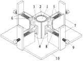
所述纵向加载装置包括一个置于岩土体试块顶部的下托盘,下托盘上方为上部支撑连接,上部支撑为一个十字架,传压轴穿过上部支撑,传压轴一端与下托盘连接,另一端与上托盘连接;上部支撑通过固定螺丝与支撑钢板连接。The longitudinal loading device includes a lower tray placed on the top of the rock and soil mass test block, above the lower tray is an upper support connection, the upper support is a cross, the pressure transmission shaft passes through the upper support, one end of the pressure transmission shaft is connected with the lower tray, and the other end It is connected with the upper tray; the upper support is connected with the supporting steel plate through fixing screws.
一种用于岩土工程试块假三轴蠕变的新型装置的使用方法,包括以下几步:A method for using a novel device for pseudo-triaxial creep of geotechnical engineering test blocks, comprising the following steps:
(1)将岩土体试块放置于装置地板中部,外围加套橡胶圈;(1) Place the rock and soil test block in the middle of the device floor, and add a rubber ring around it;
(2)将多组环绕钢板与传感器以及弹簧连接好,使环绕钢板贴紧橡胶圈,保持岩土体试块在地板中心的位置;(2) Connect multiple sets of surrounding steel plates with sensors and springs, make the surrounding steel plates stick to the rubber ring, and keep the rock and soil mass test block in the center of the floor;
(3)安置稳定后,按需要调节旋转调节螺丝控制高强度弹簧长度,当压力传感器示数达目标值且四组示数一致时停止调节;(3) After the placement is stable, adjust the rotation adjustment screw to control the length of the high-strength spring as required, and stop the adjustment when the pressure sensor reading reaches the target value and the four sets of readings are consistent;
(4)安置岩土体试块上方加载装置,在上托盘加载,计算总压力,达到目标之后停止加载;(4) Install the loading device above the rock and soil test block, load on the upper tray, calculate the total pressure, and stop loading after reaching the target;
(5)每隔一定时间量测每组环绕钢板的位移量,取其平均值作为环向位移,并做好记录,同时适当旋转调节螺丝,保证压力传感器示数恒定,最大程度上避免弹簧因蠕变产生的压力改变,减小实验误差。(5) Measure the displacement of each group of surrounding steel plates at regular intervals, take the average value as the circumferential displacement, and make a record, and at the same time properly rotate the adjustment screw to ensure that the pressure sensor shows a constant value, and to the greatest extent avoid the spring due to The pressure change caused by creep reduces the experimental error.
本发明与以往的测量方法相比具有以下优点:Compared with previous measurement methods, the present invention has the following advantages:
1本发明解决了以前实验中的诸多不便,弹簧压力简单而容易实现,便于调节;1. The present invention solves many inconveniences in previous experiments, and the spring pressure is simple and easy to realize, and it is convenient to adjust;
2通过旋转螺丝挤压弹簧的方式避免了以往装置大量繁琐机械化的控制,大幅度提升实验效率;2 By rotating the screw to squeeze the spring, it avoids a lot of cumbersome mechanized control of the previous device, and greatly improves the experimental efficiency;
3蠕变过程变形较慢,通过适时调整旋转螺丝,避免弹簧略微伸长带来的轻微误差,保证了实验精度,足以满足低强度蠕变实验的需要;3. The deformation of the creep process is relatively slow. By timely adjusting the rotating screw, the slight error caused by the slight elongation of the spring is avoided, and the accuracy of the experiment is guaranteed, which is enough to meet the needs of low-strength creep experiments;
4压力传感器的安装保证了蠕变围压的恒定,确保了低强度假三轴蠕变实验的准确性。4 The installation of the pressure sensor ensures the constant creep confining pressure and the accuracy of the low-strength false triaxial creep experiment.
5装置上方重物加载的方式较为便捷,传压轴确保了压力的垂直施加,避免偏压。5. The method of loading heavy objects above the device is more convenient, and the pressure transmission shaft ensures the vertical application of pressure and avoids bias.
附图说明Description of drawings
图1为本发明的弹簧垂直施压装置结构示意图;Fig. 1 is a schematic structural view of a spring vertical pressing device of the present invention;
图2为本发明的加载装装置结构示意图;Fig. 2 is a schematic structural view of the loading device of the present invention;
其中,1岩土体试块;2橡胶圈;3环绕钢板;4压力传感器;5弹簧侧挡板;6弹簧两端挡板;7支撑钢板;8高强度弹簧;9调节螺丝;10底板;11上托盘;12传压轴;13上部支撑;14下托盘;15;固定螺丝。Among them, 1 rock and soil test block; 2 rubber ring; 3 surrounding steel plate; 4 pressure sensor; 5 spring side baffle; 11 upper tray; 12 pressure transmission shaft; 13 upper support; 14 lower tray; 15; fixing screw.
具体实施方式Detailed ways
下面结合附图和实例对本发明做进一步说明:Below in conjunction with accompanying drawing and example the present invention will be further described:
图1、图2中,一种用于岩土工程试块假三轴蠕变的新型装置,加载装置主要包括上托盘11,下托盘14,传压轴12及上部支撑13;弹簧垂直施压装置主要包括环绕钢板3,弹簧侧挡板5和弹簧两端挡板6,高强度弹簧8,压力传感器4,调节螺丝9以及支撑钢板7。In Fig. 1 and Fig. 2, a new device for pseudo-triaxial creep of geotechnical engineering test blocks, the loading device mainly includes an
其中上部的传压轴12嵌套入十字形上部支撑13中间的圆孔中,两端分别与上下托盘11和14相连;下部分为四组相同结构的弹簧垂直施压装置,环绕钢板3外接压力传感器4,高强度弹簧8两侧为弹簧侧挡板5避免侧向变形,高强度弹簧8两端有弹簧两端挡板6,其中内侧的弹簧两端挡板6与压力传感器4相连,外侧的弹簧两端挡板6与调节螺丝9相接触,调节螺丝9穿透支撑钢板7,通过旋转调节螺丝9可调节伸入钢板的长度从而控制高强度弹簧8伸长量。Among them, the upper
一种用于岩土工程试块假三轴蠕变的新型装置,其操作方法包括以下几步:A new device for pseudo-triaxial creep of geotechnical engineering test block, its operation method includes the following steps:
(1)按实验需要选择合适的岩土体试块1放置于底板10上,外围套有橡胶圈2,使受力更加均匀。(1) According to the needs of the experiment, select a suitable rock and
(2)将环绕钢板3,压力传感器4和高强度弹簧8等装置连接好后,将四组环绕钢板3紧贴橡胶圈2放置,尽量保证试块处于底板10的中心位置。(2) After connecting the surrounding
(3)将调节螺丝9拧入支撑钢板7,并与外侧的弹簧两端挡板6接触,旋转调节螺丝9并观察压力传感器4的示数,达到预期压力值且四组压力传感器4示数一致时停止调节。(3) Screw the adjusting
(4)将传压轴12套入上部支撑13,两端分别与上下托盘11和14相连,下托盘14放置于岩土体试块1正上方,通过固定螺丝15将上部支撑与下部的支撑钢板7固定在一起。(4) Insert the
(5)在上托盘11上加载,计算上部荷载总重,达到预期压力时停止加载。(5) Load on the
(6)定期测量四组环绕钢板3的位移,取平均值作为环向蠕变位移,取下托盘14沉降位移作为试块轴向蠕变位移,做好记录。(6) Regularly measure the displacements of the four groups surrounding the
(7)记录完成后,略微旋转调节螺丝9,使压力传感器4的压力值保持恒定,尽量减少高强度弹簧8因蠕变伸长而带来的误差,之后定期重复测量。(7) After the recording is completed, turn the adjusting
本发明解决了以前实验中的诸多不便,弹簧压力简单而容易实现,便于调节;通过旋转螺丝挤压弹簧的方式避免了以往装置大量繁琐机械化的控制,大幅度提升实验效率;蠕变过程变形较慢,通过适时调整旋转螺丝,避免弹簧略微伸长带来的轻微误差,保证了实验精度;压力传感器的安装保证了蠕变围压的恒定,确保了低强度假三轴蠕变实验的准确性。与前人的装置相比,本装置操作上具明显优势,实验效率显著提高,精度上足以满足低强度蠕变实验的需要,更具实用性与推广性。The invention solves many inconveniences in the previous experiments, the spring pressure is simple and easy to realize, and is convenient to adjust; the way of rotating the screw to squeeze the spring avoids a large number of cumbersome mechanized control of the previous device, and greatly improves the experimental efficiency; the deformation in the creep process is relatively small. Slow, by timely adjusting the rotating screw, avoiding the slight error caused by the slight elongation of the spring, ensuring the accuracy of the experiment; the installation of the pressure sensor ensures the constant creep confining pressure, ensuring the accuracy of the low-strength false triaxial creep experiment . Compared with the previous devices, this device has obvious advantages in operation, the experimental efficiency is significantly improved, the accuracy is sufficient to meet the needs of low-strength creep experiments, and it is more practical and popular.
Claims (5)
Priority Applications (1)
| Application Number | Priority Date | Filing Date | Title |
|---|---|---|---|
| CN201310092740.8ACN103196746B (en) | 2013-03-21 | 2013-03-21 | Novel device for pseudo tri-axial creep of rock and earth engineering test block and using method of device |
Applications Claiming Priority (1)
| Application Number | Priority Date | Filing Date | Title |
|---|---|---|---|
| CN201310092740.8ACN103196746B (en) | 2013-03-21 | 2013-03-21 | Novel device for pseudo tri-axial creep of rock and earth engineering test block and using method of device |
Publications (2)
| Publication Number | Publication Date |
|---|---|
| CN103196746Atrue CN103196746A (en) | 2013-07-10 |
| CN103196746B CN103196746B (en) | 2015-04-22 |
Family
ID=48719439
Family Applications (1)
| Application Number | Title | Priority Date | Filing Date |
|---|---|---|---|
| CN201310092740.8AExpired - Fee RelatedCN103196746B (en) | 2013-03-21 | 2013-03-21 | Novel device for pseudo tri-axial creep of rock and earth engineering test block and using method of device |
Country Status (1)
| Country | Link |
|---|---|
| CN (1) | CN103196746B (en) |
Cited By (16)
| Publication number | Priority date | Publication date | Assignee | Title |
|---|---|---|---|---|
| CN103604697A (en)* | 2013-11-22 | 2014-02-26 | 山东大学 | Fake triaxial creeping device and method for geotechnical engineering under uniform confining pressure |
| CN104344997A (en)* | 2014-11-04 | 2015-02-11 | 同济大学 | Passive type restraint loading device for triaxial test |
| CN104880366A (en)* | 2015-05-26 | 2015-09-02 | 温州大学瓯江学院 | Soil body kinetic parameter and anisotropy tester under K0 condition |
| CN106289845A (en)* | 2016-09-01 | 2017-01-04 | 中南大学 | A kind of Quantitative study tunnel surrounding comes to nothing and the dynamic test device and method softened |
| CN106546492A (en)* | 2016-10-28 | 2017-03-29 | 中国地质大学(武汉) | A kind of Rock And Soil large scale original position triaxial creep test system |
| KR101814020B1 (en)* | 2017-08-31 | 2018-01-02 | 한국건설기술연구원 | Current Hydraulic Fracturing System for Applying Differential Stress |
| KR101814019B1 (en)* | 2017-08-31 | 2018-01-30 | 한국건설기술연구원 | Current Hydraulic Fracturing System for Applying Differential Stress |
| CN106338409B (en)* | 2016-08-31 | 2018-07-24 | 中南大学 | A kind of tunnel bottom structural stress state accurately simulates laboratory testing rig |
| CN108414348A (en)* | 2018-05-07 | 2018-08-17 | 绍兴文理学院 | A kind of true triaxial test system and its implementation of test rock |
| CN108613881A (en)* | 2018-05-07 | 2018-10-02 | 绍兴文理学院 | A kind of true triaxial test system of high temperature and the test rock under seepage effect |
| CN108918287A (en)* | 2018-09-19 | 2018-11-30 | 西安建筑科技大学 | A kind of tunnel creep model experimental rig and test method |
| CN109030210A (en)* | 2018-08-02 | 2018-12-18 | 三峡大学 | Soil body creep simulation device |
| CN109655336A (en)* | 2018-12-10 | 2019-04-19 | 三峡大学 | A method of research complex condition ground Creep Rule |
| CN110823727A (en)* | 2019-11-21 | 2020-02-21 | 安徽理工大学 | A high-voltage pulse discharge fracturing experimental platform for reforming oil and gas reservoirs |
| CN111735724A (en)* | 2020-06-23 | 2020-10-02 | 三峡大学 | A device and method for detecting in-situ creep force of rock and soil mass |
| CN113720693A (en)* | 2020-05-26 | 2021-11-30 | 中国石油天然气集团有限公司 | Experimental device and experimental method for observing hydraulic fracture |
Citations (5)
| Publication number | Priority date | Publication date | Assignee | Title |
|---|---|---|---|---|
| JP2000180323A (en)* | 1998-12-10 | 2000-06-30 | Ohbayashi Corp | Constant-load giving apparatus |
| CN1609587A (en)* | 2004-08-10 | 2005-04-27 | 中国科学院寒区旱区环境与工程研究所 | Low temperature and high pressure triaxial creep tester |
| CN101074912A (en)* | 2007-06-06 | 2007-11-21 | 河海大学 | Apparatus and method for testing cement concrete penetration performance under loading action |
| CN202631363U (en)* | 2012-07-09 | 2012-12-26 | 重庆大学 | Multi-directional stress loading device |
| CN203164055U (en)* | 2013-03-21 | 2013-08-28 | 山东大学 | Novel device for false triaxial creep of geotechnical engineering test block |
- 2013
- 2013-03-21CNCN201310092740.8Apatent/CN103196746B/ennot_activeExpired - Fee Related
Patent Citations (5)
| Publication number | Priority date | Publication date | Assignee | Title |
|---|---|---|---|---|
| JP2000180323A (en)* | 1998-12-10 | 2000-06-30 | Ohbayashi Corp | Constant-load giving apparatus |
| CN1609587A (en)* | 2004-08-10 | 2005-04-27 | 中国科学院寒区旱区环境与工程研究所 | Low temperature and high pressure triaxial creep tester |
| CN101074912A (en)* | 2007-06-06 | 2007-11-21 | 河海大学 | Apparatus and method for testing cement concrete penetration performance under loading action |
| CN202631363U (en)* | 2012-07-09 | 2012-12-26 | 重庆大学 | Multi-directional stress loading device |
| CN203164055U (en)* | 2013-03-21 | 2013-08-28 | 山东大学 | Novel device for false triaxial creep of geotechnical engineering test block |
Non-Patent Citations (2)
| Title |
|---|
| CHUNHE YANG ET AL.: ""Experimental investigation of creep behavior of salt rock"", 《INTERNATIONAL JOURNAL OF ROCK MECHANICS AND MINING SCIENCES》, vol. 36, no. 2, 28 February 1999 (1999-02-28), pages 233 - 242* |
| 范庆忠 等.: ""软岩三轴蠕变特性的试验研究"", 《岩石力学与工程学报》, vol. 26, no. 7, 31 July 2007 (2007-07-31), pages 1381 - 1385* |
Cited By (26)
| Publication number | Priority date | Publication date | Assignee | Title |
|---|---|---|---|---|
| CN103604697B (en)* | 2013-11-22 | 2015-07-22 | 山东大学 | Fake triaxial creeping device and method for geotechnical engineering under uniform confining pressure |
| CN103604697A (en)* | 2013-11-22 | 2014-02-26 | 山东大学 | Fake triaxial creeping device and method for geotechnical engineering under uniform confining pressure |
| CN104344997A (en)* | 2014-11-04 | 2015-02-11 | 同济大学 | Passive type restraint loading device for triaxial test |
| CN104880366A (en)* | 2015-05-26 | 2015-09-02 | 温州大学瓯江学院 | Soil body kinetic parameter and anisotropy tester under K0 condition |
| CN104880366B (en)* | 2015-05-26 | 2018-01-16 | 温州大学瓯江学院 | Evolution Microstructure method based on soil body kinetic parameter and anisotropy analyzer under the conditions of K0 |
| CN106338409B (en)* | 2016-08-31 | 2018-07-24 | 中南大学 | A kind of tunnel bottom structural stress state accurately simulates laboratory testing rig |
| CN106289845A (en)* | 2016-09-01 | 2017-01-04 | 中南大学 | A kind of Quantitative study tunnel surrounding comes to nothing and the dynamic test device and method softened |
| CN106289845B (en)* | 2016-09-01 | 2018-08-28 | 中南大学 | A kind of dynamic test device and method that Quantitative study tunnel surrounding comes to nothing with softening |
| CN106546492A (en)* | 2016-10-28 | 2017-03-29 | 中国地质大学(武汉) | A kind of Rock And Soil large scale original position triaxial creep test system |
| CN106546492B (en)* | 2016-10-28 | 2018-04-13 | 中国地质大学(武汉) | A kind of Rock And Soil large scale original position triaxial creep test system |
| KR101814020B1 (en)* | 2017-08-31 | 2018-01-02 | 한국건설기술연구원 | Current Hydraulic Fracturing System for Applying Differential Stress |
| KR101814019B1 (en)* | 2017-08-31 | 2018-01-30 | 한국건설기술연구원 | Current Hydraulic Fracturing System for Applying Differential Stress |
| CN108613881A (en)* | 2018-05-07 | 2018-10-02 | 绍兴文理学院 | A kind of true triaxial test system of high temperature and the test rock under seepage effect |
| CN108414348A (en)* | 2018-05-07 | 2018-08-17 | 绍兴文理学院 | A kind of true triaxial test system and its implementation of test rock |
| CN108414348B (en)* | 2018-05-07 | 2020-05-26 | 绍兴文理学院 | A true triaxial test system for testing rocks and its realization method |
| CN108613881B (en)* | 2018-05-07 | 2020-09-04 | 绍兴文理学院 | A true triaxial test system for testing rocks under high temperature and seepage |
| CN109030210A (en)* | 2018-08-02 | 2018-12-18 | 三峡大学 | Soil body creep simulation device |
| CN109030210B (en)* | 2018-08-02 | 2024-08-06 | 三峡大学 | Soil creep simulation device |
| CN108918287B (en)* | 2018-09-19 | 2023-09-19 | 西安建筑科技大学 | Tunnel creep model test device and test method |
| CN108918287A (en)* | 2018-09-19 | 2018-11-30 | 西安建筑科技大学 | A kind of tunnel creep model experimental rig and test method |
| CN109655336A (en)* | 2018-12-10 | 2019-04-19 | 三峡大学 | A method of research complex condition ground Creep Rule |
| CN109655336B (en)* | 2018-12-10 | 2021-07-23 | 三峡大学 | A method to study the creep law of rock and soil under complex conditions |
| CN110823727A (en)* | 2019-11-21 | 2020-02-21 | 安徽理工大学 | A high-voltage pulse discharge fracturing experimental platform for reforming oil and gas reservoirs |
| CN113720693A (en)* | 2020-05-26 | 2021-11-30 | 中国石油天然气集团有限公司 | Experimental device and experimental method for observing hydraulic fracture |
| CN111735724B (en)* | 2020-06-23 | 2023-03-10 | 三峡大学 | Device and method for detecting creep stress of in-situ rock-soil body |
| CN111735724A (en)* | 2020-06-23 | 2020-10-02 | 三峡大学 | A device and method for detecting in-situ creep force of rock and soil mass |
Also Published As
| Publication number | Publication date |
|---|---|
| CN103196746B (en) | 2015-04-22 |
Similar Documents
| Publication | Publication Date | Title |
|---|---|---|
| CN103196746B (en) | Novel device for pseudo tri-axial creep of rock and earth engineering test block and using method of device | |
| CN104849151B (en) | A movable plate stacked ring shearing instrument adaptable to free shear deformation | |
| CN103234821B (en) | Test apparatus and method for geotechnical engineering side slope multi-direction loading | |
| CN203164055U (en) | Novel device for false triaxial creep of geotechnical engineering test block | |
| CN102607754A (en) | Device for measuring negative skin friction of pile soil | |
| CN102877492A (en) | Negative frictional resistance pile soil displacement measuring device | |
| CN103499491B (en) | A kind of Multi-axial Loading system and loading method | |
| CN105002939B (en) | Model device and method for grouped pile field test | |
| CN103900902A (en) | Laterally constrained rock uniaxial compression test device | |
| CN108955967A (en) | A kind of device and method for simulating annular tunnel liquid filling liner supporting structure stress | |
| CN207597459U (en) | The realization device of soil lateral pressure in pile foundation model test | |
| CN103149095B (en) | Test method and test device for studying steel-soil contact surface mechanical property | |
| CN106480910A (en) | The device and method that a kind of simulation is acted on test pile end different bearer | |
| CN108827784B (en) | Experimental device and method for research on load-bearing characteristics of soil plugs in pipe piles | |
| CN107764645B (en) | A test device for high-pressure consolidation of large-sized clay | |
| CN103344485B (en) | Axial loading system and loading method | |
| CN107806117B (en) | Device and method for realizing lateral earth pressure in pile foundation model test | |
| CN109900467A (en) | A kind of device of helical spring simulation soil resistance | |
| CN103604697B (en) | Fake triaxial creeping device and method for geotechnical engineering under uniform confining pressure | |
| CN106885734B (en) | Concrete material poisson ratio measuring device and method | |
| CN216791895U (en) | A load test device with controllable confining pressure | |
| CN218331019U (en) | A Settlement Simulation Mechanism Considering the Interaction Between Foundation and Ground | |
| CN114323982A (en) | A load test device and method for providing confinement with large principal stress | |
| CN102589800A (en) | Method for calibrating soil pressure sensor in stress test of free field | |
| CN216791897U (en) | Load test device for providing lateral limit for large main stress |
Legal Events
| Date | Code | Title | Description |
|---|---|---|---|
| C06 | Publication | ||
| PB01 | Publication | ||
| C10 | Entry into substantive examination | ||
| SE01 | Entry into force of request for substantive examination | ||
| GR01 | Patent grant | ||
| CF01 | Termination of patent right due to non-payment of annual fee | Granted publication date:20150422 Termination date:20210321 | |
| CF01 | Termination of patent right due to non-payment of annual fee |