CN103196115A - Actuating device, cover plate component and lighting device provided with same - Google Patents
Actuating device, cover plate component and lighting device provided with sameDownload PDFInfo
- Publication number
- CN103196115A CN103196115ACN2012100063444ACN201210006344ACN103196115ACN 103196115 ACN103196115 ACN 103196115ACN 2012100063444 ACN2012100063444 ACN 2012100063444ACN 201210006344 ACN201210006344 ACN 201210006344ACN 103196115 ACN103196115 ACN 103196115A
- Authority
- CN
- China
- Prior art keywords
- elastic body
- actuating
- cover plate
- transmission member
- elastic
- Prior art date
- Legal status (The legal status is an assumption and is not a legal conclusion. Google has not performed a legal analysis and makes no representation as to the accuracy of the status listed.)
- Pending
Links
Images


Classifications
- F—MECHANICAL ENGINEERING; LIGHTING; HEATING; WEAPONS; BLASTING
- F03—MACHINES OR ENGINES FOR LIQUIDS; WIND, SPRING, OR WEIGHT MOTORS; PRODUCING MECHANICAL POWER OR A REACTIVE PROPULSIVE THRUST, NOT OTHERWISE PROVIDED FOR
- F03G—SPRING, WEIGHT, INERTIA OR LIKE MOTORS; MECHANICAL-POWER PRODUCING DEVICES OR MECHANISMS, NOT OTHERWISE PROVIDED FOR OR USING ENERGY SOURCES NOT OTHERWISE PROVIDED FOR
- F03G7/00—Mechanical-power-producing mechanisms, not otherwise provided for or using energy sources not otherwise provided for
- F03G7/06—Mechanical-power-producing mechanisms, not otherwise provided for or using energy sources not otherwise provided for using expansion or contraction of bodies due to heating, cooling, moistening, drying or the like
- F03G7/061—Mechanical-power-producing mechanisms, not otherwise provided for or using energy sources not otherwise provided for using expansion or contraction of bodies due to heating, cooling, moistening, drying or the like characterised by the actuating element
- F03G7/0612—Mechanical-power-producing mechanisms, not otherwise provided for or using energy sources not otherwise provided for using expansion or contraction of bodies due to heating, cooling, moistening, drying or the like characterised by the actuating element using polymers
- F—MECHANICAL ENGINEERING; LIGHTING; HEATING; WEAPONS; BLASTING
- F03—MACHINES OR ENGINES FOR LIQUIDS; WIND, SPRING, OR WEIGHT MOTORS; PRODUCING MECHANICAL POWER OR A REACTIVE PROPULSIVE THRUST, NOT OTHERWISE PROVIDED FOR
- F03G—SPRING, WEIGHT, INERTIA OR LIKE MOTORS; MECHANICAL-POWER PRODUCING DEVICES OR MECHANISMS, NOT OTHERWISE PROVIDED FOR OR USING ENERGY SOURCES NOT OTHERWISE PROVIDED FOR
- F03G7/00—Mechanical-power-producing mechanisms, not otherwise provided for or using energy sources not otherwise provided for
- F03G7/06—Mechanical-power-producing mechanisms, not otherwise provided for or using energy sources not otherwise provided for using expansion or contraction of bodies due to heating, cooling, moistening, drying or the like
- F03G7/061—Mechanical-power-producing mechanisms, not otherwise provided for or using energy sources not otherwise provided for using expansion or contraction of bodies due to heating, cooling, moistening, drying or the like characterised by the actuating element
- F03G7/0614—Mechanical-power-producing mechanisms, not otherwise provided for or using energy sources not otherwise provided for using expansion or contraction of bodies due to heating, cooling, moistening, drying or the like characterised by the actuating element using shape memory elements
- F03G7/06145—Springs
- F—MECHANICAL ENGINEERING; LIGHTING; HEATING; WEAPONS; BLASTING
- F21—LIGHTING
- F21V—FUNCTIONAL FEATURES OR DETAILS OF LIGHTING DEVICES OR SYSTEMS THEREOF; STRUCTURAL COMBINATIONS OF LIGHTING DEVICES WITH OTHER ARTICLES, NOT OTHERWISE PROVIDED FOR
- F21V29/00—Protecting lighting devices from thermal damage; Cooling or heating arrangements specially adapted for lighting devices or systems
- F21V29/50—Cooling arrangements
- F21V29/502—Cooling arrangements characterised by the adaptation for cooling of specific components
- F21V29/507—Cooling arrangements characterised by the adaptation for cooling of specific components of means for protecting lighting devices from damage, e.g. housings
- F—MECHANICAL ENGINEERING; LIGHTING; HEATING; WEAPONS; BLASTING
- F21—LIGHTING
- F21V—FUNCTIONAL FEATURES OR DETAILS OF LIGHTING DEVICES OR SYSTEMS THEREOF; STRUCTURAL COMBINATIONS OF LIGHTING DEVICES WITH OTHER ARTICLES, NOT OTHERWISE PROVIDED FOR
- F21V29/00—Protecting lighting devices from thermal damage; Cooling or heating arrangements specially adapted for lighting devices or systems
- F21V29/50—Cooling arrangements
- F21V29/70—Cooling arrangements characterised by passive heat-dissipating elements, e.g. heat-sinks
- F—MECHANICAL ENGINEERING; LIGHTING; HEATING; WEAPONS; BLASTING
- F21—LIGHTING
- F21Y—INDEXING SCHEME ASSOCIATED WITH SUBCLASSES F21K, F21L, F21S and F21V, RELATING TO THE FORM OR THE KIND OF THE LIGHT SOURCES OR OF THE COLOUR OF THE LIGHT EMITTED
- F21Y2115/00—Light-generating elements of semiconductor light sources
- F21Y2115/10—Light-emitting diodes [LED]
Landscapes
- Engineering & Computer Science (AREA)
- Chemical & Material Sciences (AREA)
- Combustion & Propulsion (AREA)
- General Engineering & Computer Science (AREA)
- Mechanical Engineering (AREA)
- Arrangement Of Elements, Cooling, Sealing, Or The Like Of Lighting Devices (AREA)
- Projection Apparatus (AREA)
Abstract
Translated fromChinese
Description
Translated fromChinese技术领域technical field
本发明涉及一种用于具有热源的装置的致动装置、一种具有该致动装置的盖板组件以及一种配备有该盖板组件的照明装置。The invention relates to an actuation device for a device with a heat source, a cover assembly with the actuation device and a lighting device equipped with the cover assembly.
背景技术Background technique
随着电子装置、特别是照明装置越来越广泛地应用在人们的日常生活中,散热也成为影响该领域发展的一个重要因素。散热效果的好坏可以直接影响照明装置的寿命和光效果。通常,部分照明装置、例如大功率LED照明装置具有外置的散热体,但这种散热体会被ID(工业设计)或外部轮廓设计所局限,并且不便于维护。另一部分照明装置具有集成在壳体内部的散热体,但壳体同时会阻碍空气对流,降低散热效果。As electronic devices, especially lighting devices, are more and more widely used in people's daily life, heat dissipation has also become an important factor affecting the development of this field. The quality of the heat dissipation effect can directly affect the life and light effect of the lighting device. Usually, some lighting devices, such as high-power LED lighting devices, have an external heat sink, but this heat sink is limited by ID (industrial design) or external contour design, and is not easy to maintain. Another part of the lighting device has a cooling body integrated inside the casing, but the casing will hinder air convection at the same time, reducing the heat dissipation effect.
为了解决以上问题,在现有技术中已经提出一种用于照明装置的自动控制系统。通过使用这种系统,可以在照明装置处于非工作状态时关闭照明装置的壳体,以便保护照明装置并且实现美观的效果;在照明装置进入工作状态时,自动控制系统使壳体打开,这样可以有利地进行散热。这种自动控制系统安装在发光模块的远离壳体的一侧上,自动控制系统中的控制模块向电机发出控制信号,用于打开和关闭盖板的传动杆在接收到控制信号以后可以将盖板打开,使被盖板封闭的散热体能直接和外界环境进行热交换。但这种照明装置的IP性能并不高,并且系统的成本高昂、结构复杂,因此出现故障的几率较高。此外在打开和关闭盖板时也会由于电机运行而产生无法避免的噪音。In order to solve the above problems, an automatic control system for lighting devices has been proposed in the prior art. By using this system, the casing of the lighting device can be closed when the lighting device is in a non-working state, so as to protect the lighting device and achieve an aesthetic effect; when the lighting device enters a working state, the automatic control system opens the casing, which can Heat dissipation is advantageously carried out. This automatic control system is installed on the side away from the housing of the light-emitting module. The control module in the automatic control system sends a control signal to the motor, and the transmission rod for opening and closing the cover can move the cover after receiving the control signal. The plate is opened, so that the radiator closed by the cover plate can directly exchange heat with the external environment. However, the IP performance of this lighting device is not high, and the cost of the system is high and the structure is complex, so the probability of failure is relatively high. In addition, when the cover is opened and closed, unavoidable noise is generated due to the operation of the motor.
发明内容Contents of the invention
为解决上述问题,本发明提出一种用于具有热源的装置的致动装置,该致动装置的尺寸小、结构简单成本低廉,并且可以低噪声高可靠性地工作。In order to solve the above problems, the present invention proposes an actuating device for a device with a heat source, which is small in size, simple in structure and low in cost, and can work with low noise and high reliability.
根据本发明提出一种用于具有热源的装置的致动装置,包括壳体、容纳在壳体中的第一弹性体和第二弹性体、致动件以及传动件,致动件设置在第一和第二弹性体之间,致动件的一端和传动件的一端可活动连接,其特征在于,第一和/或第二弹性体能取决于温度改变弹力,促使致动件在壳体中线性运动,以控制传动件的位置。According to the present invention, an actuating device for a device with a heat source is provided, which includes a housing, a first elastic body and a second elastic body accommodated in the housing, an actuating member and a transmission member, and the actuating member is arranged at the second Between the first elastic body and the second elastic body, one end of the actuating member and one end of the transmission member are movably connected, and it is characterized in that the first and/or second elastic body can change the elastic force depending on the temperature, so as to promote the actuating member in the casing Linear motion to control the position of the transmission.
本发明的构思在于,摒弃现有技术中通过电路进行致动的设计,优选地通过取决于温度的机械控制过程来实现自动控制传动件的位置。根据本发明的致动装置是偏压式致动装置,这样有利于简单地仅仅根据温度变化来控制致动件在壳体中的线性运动。也就是说,致动装置可以在温度改变时自动地改变所产生的偏压方向,由此可以使位于致动装置中的致动件在偏压的作用下,例如可以在致动装置中往复运动,由此带动传动件运动,从而为装置提供机械力。由于避免使用电机,因此根据本发明致动装置在工作时产生的噪声较小。The idea of the present invention is to abandon the prior art design of actuation through electric circuits, preferably through a temperature-dependent mechanical control process to realize automatic control of the position of the transmission member. The actuating device according to the invention is a biased actuating device, which facilitates simply controlling the linear movement of the actuating member in the housing as a function of temperature variations only. That is to say, the actuating device can automatically change the direction of the generated bias when the temperature changes, so that the actuating member located in the actuating device can be reciprocated in the actuating device under the action of the bias, for example Movement, thereby driving the movement of the transmission member, thereby providing mechanical force for the device. Since the use of an electric motor is avoided, the actuating device according to the invention generates less noise during operation.
根据本发明的一个优选的设计方案,第二弹性体是能取决于温度形变的弹性体。由此确保在温度改变时,至少第二弹性体施加在致动件上的弹力取决于温度而改变。According to a preferred design solution of the present invention, the second elastic body is an elastic body that can deform depending on temperature. This ensures that at least the spring force exerted by the second elastic body on the actuating element changes as a function of the temperature when the temperature changes.
根据本发明的一个优选的设计方案,第一弹性体是压力弹簧,第二弹性体是形状记忆弹簧。优选地,第二弹性体由形状记忆合金制成。形状记忆合金(SMA)通常由镍-钛合金制成,这种合金可以在高温中被制成具有适合弹性系数的弹簧,然后在冷却后进行压缩或变形,当该合金的温度再次达到特定温度时,可以恢复成最初的弹簧并具有足够的弹性系数。除了镍-钛合金以外,也存在钛镍铜、钛镍铁、钛镍铬等新的镍钛系形状记忆合金;除此以外还有其他种类的形状记忆合金,如:铜镍系合金、铜铝系合金、铜锌系合金、铁系合金(Fe-Mn-Si,Fe-Pd)等。According to a preferred solution of the present invention, the first elastic body is a pressure spring, and the second elastic body is a shape memory spring. Preferably, the second elastic body is made of shape memory alloy. Shape memory alloys (SMA) are usually made of nickel-titanium alloys, which can be made into springs with suitable elastic constants at high temperatures, and then compressed or deformed after cooling, when the temperature of the alloy reaches a specific temperature again. , it can return to the original spring and has a sufficient elastic coefficient. In addition to nickel-titanium alloys, there are also new nickel-titanium-based shape memory alloys such as titanium-nickel-copper, titanium-nickel-iron, and titanium-nickel-chromium; in addition, there are other types of shape memory alloys, such as: copper-nickel alloys, copper Aluminum-based alloys, copper-zinc-based alloys, iron-based alloys (Fe-Mn-Si, Fe-Pd), etc.
根据本发明的一个优选的设计方案,壳体的至少部分区域由导热材料制成,第二弹性体抵压在该区域上的一端和热源热接触。由此可以将热源的热量良好地传导给第二弹性体,以便其根据热量、特别是温度的变化改变自身的形变,以提供不同的弹力。According to a preferred solution of the present invention, at least part of the area of the housing is made of heat-conducting material, and one end of the second elastic body pressed against this area is in thermal contact with the heat source. Therefore, the heat from the heat source can be well conducted to the second elastic body, so that it can change its own deformation according to the heat, especially the temperature change, so as to provide different elastic forces.
根据本发明的一个优选的设计方案,第一弹性体形变产生的第一弹力和第二弹性体受热形变产生的第二弹力共同施加在致动件上,第一和第二弹性力作用在同一直线上,并且方向相反。由此可以保证致动件在受压状态下可以线性地运动。According to a preferred design solution of the present invention, the first elastic force generated by the deformation of the first elastic body and the second elastic force generated by the thermal deformation of the second elastic body are jointly applied to the actuator, and the first and second elastic forces act on the same straight and in opposite directions. This ensures that the actuator can move linearly in the pressed state.
根据本发明的一个优选的设计方案,致动装置具有第一状态和第二状态,其中在第一状态时第二弹力大于第一弹力,在第二状态时第二弹力小于第一弹力。在第一和第二弹性体在各个状态时的合力不同,由此可以促使致动件在壳体中运动。此外在第一状态和第二状态之间还存在过渡状态,在过渡状态中,第一弹力和第二弹力的绝对值可以暂时相等。According to a preferred solution of the present invention, the actuating device has a first state and a second state, wherein in the first state, the second elastic force is greater than the first elastic force, and in the second state, the second elastic force is smaller than the first elastic force. The resultant forces of the first and second elastic bodies are different when they are in various states, so that the actuator can be urged to move in the housing. Furthermore, there is a transition state between the first state and the second state, in which the absolute values of the first spring force and the second spring force can temporarily be equal.
根据本发明的一个优选的设计方案,壳体为纵向上开设有槽的套筒,致动件的一端伸出槽和传动件的一端铰接。通过将壳体设计为具有槽的套筒,可以将第一和第二弹性体固定地保持在其中,槽特别地为致动件提供导向作用,以确保致动件部分地伸出壳体并仅仅线性地往复运动。According to a preferred design solution of the present invention, the casing is a sleeve with a groove in the longitudinal direction, and one end of the actuating member protrudes from the groove and is hinged to one end of the transmission member. By designing the housing as a sleeve with grooves, the first and second elastomeric bodies can be held fixedly therein, the grooves in particular providing a guide for the actuating member to ensure that the actuating member protrudes partially out of the housing and Only linear reciprocating motion.
根据本发明的一个优选的设计方案,传动件设计为一端安装有转轴的杆形传动件,传动件的一端利用转轴与致动件可旋转连接。通过转轴可以在致动件和传动件之间实现低损耗的力传递。According to a preferred design solution of the present invention, the transmission member is designed as a rod-shaped transmission member with a rotating shaft installed at one end, and one end of the transmission member is rotatably connected to the actuating member by the rotating shaft. A low-loss force transmission between the actuating part and the transmission part can be achieved via the rotating shaft.
此外本发明的另一个目的通过一种包括盖板的盖板组件来实现,该盖板组件还包括上述致动装置,其中致动装置的传动件的另一端和盖板可活动连接。由此可以利用结构简单的致动装置在温度改变的情况下控制盖板的运动,例如在热源的温度较低时关闭盖板,在热源的温度较高时打开盖板。优选地,传动件的另一端安装有转轴,通过转轴将传动件和盖板可活动连接。In addition, another object of the present invention is achieved by a cover plate assembly including the cover plate, and the cover plate assembly further includes the above-mentioned actuating device, wherein the other end of the transmission member of the actuating device is movably connected to the cover plate. In this way, the movement of the cover can be controlled by means of a structurally simple actuating device in the event of a temperature change, for example closing the cover when the temperature of the heat source is low and opening the cover when the temperature of the heat source is high. Preferably, a rotating shaft is installed at the other end of the transmission member, through which the transmission member and the cover plate are movably connected.
本发明的另一个目的通过一种照明装置来实现,该照明装置包括作为热源的发光模块和承载发光模块的本体,其特征在于,照明装置还配备有上述盖板组件,盖板组件安装在照明装置内部,其中盖板组件的壳体的至少部分区域和热源热接触,盖板可以覆盖照明装置的至少部分外表面。Another object of the present invention is achieved by a lighting device, which includes a light-emitting module as a heat source and a body carrying the light-emitting module. Inside the device, where at least a portion of the housing of the cover assembly is in thermal contact with the heat source, the cover may cover at least part of an exterior surface of the lighting device.
根据本发明的照明装置可以通过内部的温度变化、即根据作为热源的发光模块的工作状态来自动地控制用于覆盖至少部分照明装置的表面的盖板。例如在照明装置处于工作状态时,发光模块产生的热量使盖板组件中的致动装置工作,自动地将盖板打开,以便照明装置的内部部件、例如散热体等可以和外界直接进行热交换;而在照明装置处于非工作状态时,发光模块并不产生热量,照明装置内部的温度降低,由此使盖板自动关闭,从而避免外界的灰尘或污染物进入照明装置内部。The lighting device according to the present invention can automatically control the cover plate for covering at least part of the surface of the lighting device according to the internal temperature change, that is, according to the working state of the light emitting module as a heat source. For example, when the lighting device is in the working state, the heat generated by the light emitting module makes the actuating device in the cover plate assembly work, and the cover plate is automatically opened, so that the internal components of the lighting device, such as heat sinks, can directly exchange heat with the outside world ; and when the lighting device is in non-working state, the light emitting module does not generate heat, and the temperature inside the lighting device decreases, thereby automatically closing the cover, thereby preventing external dust or pollutants from entering the lighting device.
根据本发明的一个优选的设计方案提出,主体包括导热区域,其中致动装置的区域通过导热区域和热源热接触。在此情况下,致动装置的用于导热的区域经过导热区域和热源间接地热接触,由于导热区域导热性能良好,因此不会对热源和致动装置之间的热传递产生不良的影响。According to a preferred design solution of the present invention, the main body includes a heat conduction area, wherein the area of the actuating device is in thermal contact with the heat source through the heat conduction area. In this case, the heat conduction area of the actuator device is in indirect thermal contact with the heat source through the heat conduction area. Since the heat conduction area has good heat conduction performance, it will not adversely affect the heat transfer between the heat source and the actuator device.
优选地,壳体一体地形成在照明装置中。由此实现了照明装置内部的紧凑性。也可以在照明装置中直接开设长形的容纳部,用于替代壳体容纳第一和第二弹性体以及致动件。Preferably, the housing is integrally formed in the lighting device. This achieves a compact interior of the lighting device. An elongated receiving portion can also be directly provided in the illuminating device to accommodate the first and second elastic bodies and the actuator instead of the housing.
附图说明Description of drawings
附图构成本说明书的一部分,用于帮助进一步理解本发明。这些附图图解了本发明的实施例,并与说明书一起用来说明本发明的原理。在附图中相同的部件用相同的标号表示。图中示出:The accompanying drawings constitute a part of this specification and are provided to help further understanding of the invention. The drawings illustrate embodiments of the invention and together with the description serve to explain the principles of the invention. The same components are denoted by the same reference numerals in the drawings. The figure shows:
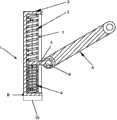
图1是根据本发明的第一实施例的致动装置的纵向截面图;1 is a longitudinal sectional view of an actuator device according to a first embodiment of the present invention;
图2是根据本发明的第二实施例的照明装置的截面图,其中安装有图1中示出的盖板组件;2 is a cross-sectional view of a lighting device according to a second embodiment of the present invention, wherein the cover plate assembly shown in FIG. 1 is installed;
图3是图2的局部放大图。FIG. 3 is a partially enlarged view of FIG. 2 .
具体实施方式Detailed ways
图1示出了根据本发明的第一实施例的致动装置的纵向截面图。在优选地设计为套筒的壳体2中顺次地安装有第一弹性体3、致动件5和第二弹性体4,其中致动件5的一端伸出纵向上开设在壳体2上的槽7和传动件6可活动连接。第一和第二弹性体3,4优选地设计为弹簧,第一弹性件3受压地位于壳体2的顶面和致动件5之间;第二弹性体4受压地位于壳体2的底面和致动件5之间,因此可以将致动件5固定地夹持在第一和第二弹性体3,4之间。在图1中,第一弹性体3向致动件5施加垂直向下的第一弹力F1,第二弹性体4向致动件5施加垂直向上的第二弹力F2。这两个弹力的方向相反,并且作用在同一直线上,因此可以形成施加在致动件5上的合力。Fig. 1 shows a longitudinal sectional view of an actuating device according to a first embodiment of the invention. A first
第一和第二弹性体3,4中的至少一个(在本实施例中是位于致动件5下方的第二弹性体4)是由形状记忆合金制成。这种形状记忆合金制成的第二弹性体4在例如常温的第一温度范围中时具有第一弹性系数k1,在例如被加热处于预定的第二温度范围中时具有第二弹性系数k2,在此k2>k1。壳体2的底面设计为能导热的区域B,第二弹性体4通过区域B可以和热源10热接触。由此可以利用温度的改变使第二弹性体4形变产生的第二弹力F2自动改变。At least one of the first and second
为了根据温度的改变使致动件5自动地带动传动件6运动,特别地将根据本发明的致动装置1设计为偏压式致动装置。具体地说,利用形状记忆合金的特性,将第二弹性体4设计为偏压式致动装置中的主动部件,第一弹性体3相应地被用作被动部件。例如在热源10产生热量时,第二弹性体4受热形变,第二弹力F2大于第一弹力F1,使致动装置1处于第一状态,即致动件5在合力F2-F1的作用下朝向壳体2的顶面运动;在热源10不产生热量时,第二弹力F2小于第一弹力F1,使致动装置1处于第二状态,即致动件5在合力F1-F2在作用下向朝向壳体2的底面运动。In order to make the actuating
可以有利地利用转轴8将致动件5和传动件6连接,从而使致动件5带动传动件6共同运动,并且尽可能地减少两者之间的力损耗。也可以以铰接的方式将致动件5和传动件6连接。在另一个优选的实施例中,可以直接在致动件5用于连接传动件6的端部上设置凸起,在传动件6的端部上设置相应的环形容纳部,以实现致动件5和传动件6的可活动连接。Advantageously, the
图2是根据本发明的第二实施例的照明装置的截面图,其中安装有根据本发明的盖板组件。盖板组件包括图1中示出的致动装置1以及和传动件6的另一端可活动连接的盖板9。盖板组件安装在照明装置内部,其中致动装置1的区域B和照明装置的热源10热接触。在本实施例中,照明装置的发光模块被视为热源10。Fig. 2 is a cross-sectional view of a lighting device according to a second embodiment of the present invention, in which the cover plate assembly according to the present invention is installed. The cover plate assembly includes the actuating device 1 shown in FIG. 1 and the
参照图3中示出的照明装置的局部放大图可以看出,致动装置1安装在照明装置内部,在一个优选的实施例中,致动装置1的壳体2可以一体地形成在照明装置中。在一个未示出的实施例中,也可以在照明装置中开设长形的容纳部,用于替代壳体2容纳第一和第二弹性体3,4以及致动件5。Referring to the partially enlarged view of the lighting device shown in FIG. 3, it can be seen that the actuating device 1 is installed inside the lighting device. In a preferred embodiment, the
在照明装置内部,热源10安装在主体12上,通过主体12的一部分、即导热区域13可以将热源10产生的热量通过区域B传递给第二弹性体4,形成间接的热接触。由此可以实现:在照明装置处于工作状态时,热源10产生的热量使盖板组件中的致动装置1工作,自动地将盖板9打开,以便照明装置可以和外界直接进行热交换;而在照明装置处于非工作状态时,光源10并不产生热量,照明装置内部的温度降低,由此使盖板9自动关闭,从而避免外界的灰尘或污染物进入照明装置内部。Inside the lighting device, the
以上仅为本发明的优选实施例而已,并不用于限制本发明,对于本领域的技术人员来说,本发明可以有各种更改和变化。凡在本发明的精神和原则之内所作的任何修改、等同替换、改进等,均应包含在本发明的保护范围之内。The above are only preferred embodiments of the present invention, and are not intended to limit the present invention. For those skilled in the art, the present invention may have various modifications and changes. Any modification, equivalent replacement, improvement, etc. made within the spirit and principle of the present invention shall be included within the protection scope of the present invention.
参考标号reference number
1 致动装置1 Actuating device
2 壳体2 shell
3 第一弹性体3 The first elastic body
4 第二弹性体4 Second elastic body
5 致动件5 actuators
6 传动件6 transmission parts
7 槽7 slots
8 转轴8 shafts
9 盖板9 cover
10 热源10 heat sources
12 本体12 body
13 导热区域13 heat conduction area
B 壳体的部分区域Part of the B shell
F1 第一弹力F1 first stretch
F2 第二弹力F2 second elastic
Claims (14)
Translated fromChinesePriority Applications (2)
| Application Number | Priority Date | Filing Date | Title |
|---|---|---|---|
| CN2012100063444ACN103196115A (en) | 2012-01-10 | 2012-01-10 | Actuating device, cover plate component and lighting device provided with same |
| PCT/EP2012/075754WO2013104491A2 (en) | 2012-01-10 | 2012-12-17 | Actuator, cover-plate assembly having the actuator and illuminating device |
Applications Claiming Priority (1)
| Application Number | Priority Date | Filing Date | Title |
|---|---|---|---|
| CN2012100063444ACN103196115A (en) | 2012-01-10 | 2012-01-10 | Actuating device, cover plate component and lighting device provided with same |
Publications (1)
| Publication Number | Publication Date |
|---|---|
| CN103196115Atrue CN103196115A (en) | 2013-07-10 |
Family
ID=47557038
Family Applications (1)
| Application Number | Title | Priority Date | Filing Date |
|---|---|---|---|
| CN2012100063444APendingCN103196115A (en) | 2012-01-10 | 2012-01-10 | Actuating device, cover plate component and lighting device provided with same |
Country Status (2)
| Country | Link |
|---|---|
| CN (1) | CN103196115A (en) |
| WO (1) | WO2013104491A2 (en) |
Cited By (8)
| Publication number | Priority date | Publication date | Assignee | Title |
|---|---|---|---|---|
| CN106481996A (en)* | 2016-11-22 | 2017-03-08 | 遵义市义阳光电有限公司 | A kind of LED |
| CN107228318A (en)* | 2017-06-29 | 2017-10-03 | 东莞市闻誉实业有限公司 | Tube spotlight |
| CN107314284A (en)* | 2017-06-29 | 2017-11-03 | 东莞市闻誉实业有限公司 | Double lamp plate ligthing paraphernalias |
| CN107327769A (en)* | 2017-07-26 | 2017-11-07 | 东莞市闻誉实业有限公司 | Snap-in lamps |
| CN107345650A (en)* | 2017-06-29 | 2017-11-14 | 东莞市闻誉实业有限公司 | Outdoor lighting lamp |
| CN107435872A (en)* | 2017-08-30 | 2017-12-05 | 东莞市闻誉实业有限公司 | reflective light emitting device |
| CN107606528A (en)* | 2017-08-30 | 2018-01-19 | 东莞市闻誉实业有限公司 | spotlight |
| CN108869216A (en)* | 2018-06-19 | 2018-11-23 | 北京航空航天大学 | A kind of non-firer's paraffin driver of Rapid reset using SMA spring |
Family Cites Families (5)
| Publication number | Priority date | Publication date | Assignee | Title |
|---|---|---|---|---|
| NL294816A (en)* | 1963-05-08 | 1900-01-01 | ||
| EP0107900A1 (en)* | 1982-09-21 | 1984-05-09 | Blazer International Corp. | Improved lamp comprising automatically actuated louver system |
| WO2008120255A1 (en)* | 2007-04-03 | 2008-10-09 | Fontanaarte S.P.A. | Lighting device |
| JP4832373B2 (en)* | 2007-07-10 | 2011-12-07 | オリンパス株式会社 | Shape memory alloy actuator |
| DE102008027541B4 (en)* | 2008-06-10 | 2017-04-06 | Günther Zimmer | Actuating device for pieces of furniture with at least one shape memory element |
- 2012
- 2012-01-10CNCN2012100063444Apatent/CN103196115A/enactivePending
- 2012-12-17WOPCT/EP2012/075754patent/WO2013104491A2/enactiveApplication Filing
Cited By (12)
| Publication number | Priority date | Publication date | Assignee | Title |
|---|---|---|---|---|
| CN106481996A (en)* | 2016-11-22 | 2017-03-08 | 遵义市义阳光电有限公司 | A kind of LED |
| CN106481996B (en)* | 2016-11-22 | 2019-01-25 | 遵义市义阳光电有限公司 | A kind of LED light |
| CN107228318A (en)* | 2017-06-29 | 2017-10-03 | 东莞市闻誉实业有限公司 | Tube spotlight |
| CN107314284A (en)* | 2017-06-29 | 2017-11-03 | 东莞市闻誉实业有限公司 | Double lamp plate ligthing paraphernalias |
| CN107345650A (en)* | 2017-06-29 | 2017-11-14 | 东莞市闻誉实业有限公司 | Outdoor lighting lamp |
| CN107314284B (en)* | 2017-06-29 | 2020-05-05 | 东莞市闻誉实业有限公司 | Double-lamp-plate lighting device |
| CN107327769A (en)* | 2017-07-26 | 2017-11-07 | 东莞市闻誉实业有限公司 | Snap-in lamps |
| CN107327769B (en)* | 2017-07-26 | 2020-03-24 | 东莞市闻誉实业有限公司 | Clamping type lamp |
| CN107435872A (en)* | 2017-08-30 | 2017-12-05 | 东莞市闻誉实业有限公司 | reflective light emitting device |
| CN107606528A (en)* | 2017-08-30 | 2018-01-19 | 东莞市闻誉实业有限公司 | spotlight |
| CN107435872B (en)* | 2017-08-30 | 2020-10-23 | 东莞市闻誉实业有限公司 | Reflective light emitting device |
| CN108869216A (en)* | 2018-06-19 | 2018-11-23 | 北京航空航天大学 | A kind of non-firer's paraffin driver of Rapid reset using SMA spring |
Also Published As
| Publication number | Publication date |
|---|---|
| WO2013104491A3 (en) | 2014-04-24 |
| WO2013104491A2 (en) | 2013-07-18 |
Similar Documents
| Publication | Publication Date | Title |
|---|---|---|
| CN103196115A (en) | Actuating device, cover plate component and lighting device provided with same | |
| US8939427B2 (en) | Arrangement for adjusting a valve | |
| JP4287505B1 (en) | Closed shock absorber for furniture door | |
| US8956021B2 (en) | Aircraft light | |
| CN105811640A (en) | Motor assembly | |
| WO2014119048A1 (en) | Thermo valve | |
| US20090237887A1 (en) | Electronic device | |
| DE502006005441D1 (en) | Heat exchanger valve control attachment, in particular radiator valve thermostatic attachment, with thermoelectric generator | |
| EP1965051A4 (en) | Engine assembly with variable stroke characteristics | |
| US20210212236A1 (en) | Phase-change mechanically deformable cooling device | |
| JP6321641B2 (en) | Heat transfer device, luminaire and method of assembling luminaire | |
| US20210381593A1 (en) | Actuator for a motor vehicle | |
| JP6609168B2 (en) | Valve actuator | |
| CN210246819U (en) | Electronic device | |
| JP2014170744A (en) | System for cooling devices | |
| CN101286485A (en) | semiconductor module | |
| CN107077985B (en) | Operating device for vehicle, particularly passenger car | |
| CN107110144A (en) | Reciprocating compressor valve gear | |
| JP4722505B2 (en) | Imaging device | |
| CN101270701A (en) | Thermally driven actuator | |
| CN103822009B (en) | Actuator | |
| US10738864B2 (en) | Linear drive apparatus | |
| CN106401788B (en) | Stirling cycle engine | |
| EP3502556A1 (en) | Automotive lighting device | |
| CN119871540B (en) | Pull formula heat abstractor and robot |
Legal Events
| Date | Code | Title | Description |
|---|---|---|---|
| C06 | Publication | ||
| PB01 | Publication | ||
| C05 | Deemed withdrawal (patent law before 1993) | ||
| WD01 | Invention patent application deemed withdrawn after publication | Application publication date:20130710 |