CN103191528A - Ultrasound phase control array focus mode high-speed switching system and focus mode synthetic method - Google Patents
Ultrasound phase control array focus mode high-speed switching system and focus mode synthetic methodDownload PDFInfo
- Publication number
- CN103191528A CN103191528ACN2013100936426ACN201310093642ACN103191528ACN 103191528 ACN103191528 ACN 103191528ACN 2013100936426 ACN2013100936426 ACN 2013100936426ACN 201310093642 ACN201310093642 ACN 201310093642ACN 103191528 ACN103191528 ACN 103191528A
- Authority
- CN
- China
- Prior art keywords
- phase
- sine wave
- amplitude
- phased array
- microcontroller
- Prior art date
- Legal status (The legal status is an assumption and is not a legal conclusion. Google has not performed a legal analysis and makes no representation as to the accuracy of the status listed.)
- Granted
Links
Images

Landscapes
- Investigating Or Analyzing Materials By The Use Of Ultrasonic Waves (AREA)
Abstract
Translated fromChinese
Description
Translated fromChinese技术领域technical field
本发明涉及生物医学工程技术领域,具体地,涉及一种超声相控阵列聚焦模式高速切换系统及聚焦模式合成方法。The invention relates to the technical field of biomedical engineering, in particular to an ultrasonic phased array focus mode high-speed switching system and a focus mode synthesis method.
背景技术Background technique
相控型聚焦超声是新一代聚焦超声技术,它通过调控超声相控阵列内任意阵元激励正弦波信号的幅度和相位,将体外超声波束汇聚于一点或多点,该点(即焦点)在三维声场分布中具有声压幅度最大的特性,从理论上说,通过切换焦点的空间位置和时间分布可实现设定的超声能量分布和温度场结果。聚焦模式合成以及不同聚焦模式间切换是相控型聚焦超声系统的关键核心技术,以下将相控型聚焦超声系统简写为相控系统。聚焦模式合成是相控系统实现超声能量空间分布的唯一手段,不同聚焦模式间切换则是相控系统调整超声能量空间和时间分布的实现方式,间接影响温度场分布结果。对相控系统而言,合成单组聚焦模式须产生对应相控阵列内各阵元的激励正弦波信号,不同聚焦模式间切换则需要改变对应激励正弦波信号的幅度和相位。因此,要实现超声能量的精确时空分布,必须提高相邻聚焦模式的切换速度和频率,这就需要一个针对超声相控阵列的聚焦模式高速切换系统。Phase-controlled focused ultrasound is a new generation of focused ultrasound technology. It focuses the external ultrasound beam on one or more points by regulating the amplitude and phase of the sine wave signal excited by any element in the ultrasonic phased array. The three-dimensional sound field distribution has the characteristic of the largest sound pressure amplitude. Theoretically speaking, the set ultrasonic energy distribution and temperature field results can be achieved by switching the spatial position and time distribution of the focal point. Focus mode synthesis and switching between different focus modes are the key core technologies of the phase-controlled focused ultrasound system. The phase-controlled focused ultrasound system will be abbreviated as the phase-controlled system below. Focusing mode synthesis is the only way for the phase control system to realize the spatial distribution of ultrasonic energy, and switching between different focusing modes is the way for the phase control system to adjust the spatial and temporal distribution of ultrasonic energy, which indirectly affects the temperature field distribution results. For a phased system, synthesizing a single focus mode must generate an excitation sine wave signal corresponding to each array element in the phased array, and switching between different focus modes requires changing the amplitude and phase of the corresponding excitation sine wave signal. Therefore, in order to realize the precise temporal and spatial distribution of ultrasonic energy, the switching speed and frequency of adjacent focusing modes must be increased, which requires a high-speed switching system for focusing modes for ultrasonic phased arrays.
经对现有技术的文献检索发现,中国专利授权公告号为CN101862511B,2012.04.25授权,由上海交通大学申请的发明专利《多通道高精度相控信号发生装置》披露了“一种多通道高精度相控信号发生装置,具体结构包括高精度有源晶振、现场可编程门阵列芯片、可编程只读存储器和I/O接口板,由电源模块为整个装置供电。所述可编程只读存储器存储现场可编程门阵列芯片的程序和配置信息。所述现场可编程门阵列芯片通过从可编程只读存储器中读取程序和配置信息,生成相移模块、相位译码模块、地址译码模块及若干个多路选通器。上位机提供的相位控制信号和通道控制信号通过I/O接口板分别连接到相位译码模块和地址译码模块,两个模块的输出分别连接到每一个多路选通器。高精度有源晶振作为系统信源,产生的时钟信号连接相移模块,其输出连接到每一个多路选通器。各个多路选通器并行工作:每个多路选通器根据上位机提供的相位控制信号确定输出信号的相位值;多路选通器输出的方波信号通过I/O接口板连接外部推挽式功率放大器。I/O接口板实现现场可编程门阵列芯片与输出信号之间的光电隔离,并将现场可编程门阵列芯片3.3V的高电平电压输出提升为I/O接口板5V的高电平电压输出。”该技术存在以下三点不足:第一,一次“上位机提供的相位控制信号和通道控制信号”仅能合成单组聚焦模式,若需切换聚焦模式,上位机不得不重新发送新的相位控制信号和通道控制信号至“相位译码模块和地址译码模块”,进而发送一次信号无法实现多组聚焦模式的切换;第二,相邻聚焦模式间的切换很大程度上依赖上位机和现场可编程门阵列芯片内对应模块之间的数据传输,而I/O接口板传输速度的瓶颈限制了多组聚焦模式间的切换速度,进而影响相控系统对超声能量时空分布的精确调控;第三,该多通道高精度相控信号发生装置缺乏锁相环电路,因此无法对存在相位误差的“输出的方波信号”进行调整,进而不能实现输出信号与设定相位信号的同步。After searching the literature of the existing technology, it was found that the Chinese patent authorization announcement number is CN101862511B, authorized on 2012.04.25, and the invention patent "multi-channel high-precision phase control signal generator" applied by Shanghai Jiaotong University disclosed "a multi-channel high-precision A precision phase control signal generating device, the specific structure includes a high-precision active crystal oscillator, a field programmable gate array chip, a programmable read-only memory and an I/O interface board, and the power supply module supplies power to the entire device. The programmable read-only memory Store the program and configuration information of field programmable gate array chip.Described field programmable gate array chip generates phase shift module, phase decoding module, address decoding module by reading program and configuration information from programmable read-only memory and several multiplexers. The phase control signal and channel control signal provided by the host computer are respectively connected to the phase decoding module and the address decoding module through the I/O interface board, and the outputs of the two modules are respectively connected to each multiple Road selector. The high-precision active crystal oscillator is used as the system source, and the generated clock signal is connected to the phase shift module, and its output is connected to each multiplexer. Each multiplexer works in parallel: each multiplexer The passer determines the phase value of the output signal according to the phase control signal provided by the host computer; the square wave signal output by the multiplexer is connected to the external push-pull power amplifier through the I/O interface board. The I/O interface board realizes field programming The optical isolation between the gate array chip and the output signal, and the 3.3V high-level voltage output of the field programmable gate array chip is raised to the 5V high-level voltage output of the I/O interface board." This technology has the following three points Disadvantages: First, the "phase control signal and channel control signal provided by the host computer" can only synthesize a single focus mode. If the focus mode needs to be switched, the host computer has to resend a new phase control signal and channel control signal to the " Phase decoding module and address decoding module", and then sending a signal cannot realize the switching of multiple groups of focus modes; second, the switching between adjacent focus modes largely depends on the correspondence between the host computer and the field programmable gate array chip. Data transmission between modules, and the bottleneck of the transmission speed of the I/O interface board limits the switching speed between multiple groups of focusing modes, which in turn affects the precise regulation of the phase control system on the temporal and spatial distribution of ultrasonic energy; third, the multi-channel high-precision The phase control signal generating device lacks a phase-locked loop circuit, so it cannot adjust the "output square wave signal" with phase error, and thus cannot realize the synchronization of the output signal and the set phase signal.
经对现有技术的文献检索还发现,中国专利申请公布号为CN102231625A,2011.11.02申请公布,由哈尔滨工程大学申请的《一种相控信号发生器及相控方法》披露了“一种可以使信号源的规模大大降低的相控信号发生器和一种相控方法,相控信号发生器由多个基本信号产生单元构成,每个基本信号产生单元又包含可控相移信号产生电路、幅度控制及驱动电路和单路-多路信号转接头,三者依次电信号连接;可控相移信号产生电路产生具有一定相移的信号;幅度控制及驱动电路用来控制输出信号的幅度,并提供驱动能力;单路-多路信号转接头将可控相移信号产生电路产生的并经幅度控制及驱动电路的单路信号分接成相同的多路信号,这些多路信号对应于被测多波束系统不同的输入端。”该技术存在明显不足:由于相控信号发生器和“被测多波束系统”内对应基元间存在电缆连接,每根电缆具有特性阻抗(与电缆的感抗和容抗有关),但该发生器内部缺乏阻抗匹配电路,因此,“被测多波束系统”的输入信号和相控信号发生器的输出信号之间会存在差别,表现为信号幅度和相位的不同。虽然单路输入信号的误差并不大,但随着基元数量的大幅增加,“被测多波束系统”输入信号的整体误差将变得不可忽略,进而影响“波束形成”效果。After searching the literature of the prior art, it is also found that the Chinese patent application publication number is CN102231625A, which was published on 2011.11.02, and the "A Phase Control Signal Generator and Phase Control Method" applied by Harbin Engineering University discloses "a kind of A phase control signal generator and a phase control method that greatly reduce the scale of signal sources. The phase control signal generator is composed of a plurality of basic signal generating units, and each basic signal generating unit includes a controllable phase shift signal generating circuit, Amplitude control and drive circuit and single-channel-multi-channel signal adapter, the three are connected by electrical signals in turn; the controllable phase shift signal generation circuit generates a signal with a certain phase shift; the amplitude control and drive circuit is used to control the amplitude of the output signal, And provide driving ability; the single-channel-multi-channel signal adapter taps the single-channel signal generated by the controllable phase-shift signal generating circuit and passed through the amplitude control and driving circuit into the same multiple-channel signal, and these multiple-channel signals correspond to the Different input ends of the multi-beam system to be tested.” This technique has obvious disadvantages: since there is a cable connection between the phase-controlled signal generator and the corresponding primitive in the “multi-beam system under test”, each cable has a characteristic impedance (compared to the inductance of the cable). reactance and capacitive reactance), but the generator lacks an impedance matching circuit inside, therefore, there will be a difference between the input signal of the "multi-beam system under test" and the output signal of the phase-controlled signal generator, which is expressed as signal amplitude and phase s difference. Although the error of a single input signal is not large, with the substantial increase in the number of primitives, the overall error of the input signal of the "multi-beam system under test" will become non-negligible, which will affect the effect of "beamforming".
发明内容Contents of the invention
针对现有技术中的缺陷,本发明的目的是提供一种可以在多个聚焦模式间高速切换的超声相控阵列聚焦模式高速切换系统及聚焦模式合成方法。In view of the defects in the prior art, the purpose of the present invention is to provide an ultrasonic phased array focus mode high-speed switching system and a focus mode synthesis method that can switch between multiple focus modes at high speed.
根据本发明的一个方面,提供一种超声相控阵列聚焦模式高速切换系统,包括:上位机、上/下位机通讯接口、微控制器、存储器、幅相控制信号发生器和超声相控阵列,微控制器通过上/下位机通讯接口与上位机连接,存储器与微控制器连接,幅相控制信号发生器分别与微控制器、上位机和超声相控阵列连接,微控制器通过上/下位机通讯接口与上位机进行数据接收和发送,同时将相关数据存入存储器,当微控制器接收到上位机发送的控制命令,随即取出存储器内相关数据,并将相关数据发送至幅相控制信号发生器,幅相控制信号发生器根据接收到的数据产生合成聚焦模式或高速切换不同聚焦模式所需的多路正弦波信号,并发送至超声相控阵列激励超声相控阵列内对应阵元。According to one aspect of the present invention, a high-speed switching system for ultrasonic phased array focus mode is provided, including: a host computer, an upper/lower computer communication interface, a microcontroller, a memory, an amplitude and phase control signal generator, and an ultrasonic phased array, The microcontroller is connected to the host computer through the upper/lower computer communication interface, the memory is connected to the microcontroller, the amplitude and phase control signal generator is respectively connected to the microcontroller, the upper computer and the ultrasonic phased array, and the microcontroller is connected through the upper/lower bit The computer communication interface receives and sends data with the upper computer, and stores the relevant data in the memory at the same time. When the microcontroller receives the control command sent by the upper computer, it immediately takes out the relevant data in the memory and sends the relevant data to the amplitude and phase control signal. Generator, amplitude and phase control signal generator generates multi-channel sine wave signals required for synthetic focus mode or high-speed switching of different focus modes according to the received data, and sends them to the ultrasonic phased array to excite the corresponding elements in the ultrasonic phased array.
优选地,微控制器通过上/下位机通讯接口与上位机进行传输的数据包括接收部分和发送部分,其中,接收部分至少包括聚焦模式信息和控制命令信息,聚焦模式信息至少包括各组聚焦模式对应的序号、焦点三维坐标以及超声相控阵列激励正弦波信号的幅度和相位;控制命令信息至少包括开启或停止输出激励正弦波信号指令、各组聚焦模式对应的焦点三维坐标、激励正弦波信号的输出开启时间和输出停止时间;发送部分至少包括各组聚焦模式对应激励正弦波信号的反馈信息,该信息至少包括单组聚焦模式对应激励正弦波信号的输出结束反馈信息。Preferably, the data transmitted between the microcontroller and the host computer through the upper/lower computer communication interface includes a receiving part and a sending part, wherein the receiving part includes at least focus mode information and control command information, and the focus mode information includes at least each group of focus mode Corresponding serial numbers, three-dimensional coordinates of the focal point, and the amplitude and phase of the ultrasonic phased array excitation sine wave signal; the control command information includes at least the command to start or stop outputting the excitation sine wave signal, the three-dimensional coordinates of the focal point corresponding to each group of focus modes, and the excitation sine wave signal The output start time and output stop time; the sending part at least includes the feedback information of the excitation sine wave signal corresponding to each group of focus modes, and the information at least includes the output end feedback information of the excitation sine wave signal corresponding to the single focus mode.
优选地,幅相控制信号发生器至少包括相控信号发生器、幅度控制及功率放大驱动电路、幅相控制信号输出接口、超声相控阵列内对应阵元的声阻抗匹配电路和电功率反馈电路,相控信号发生器用以接收微控制器发出的激励正弦波信号的相位信息、输出开启时间和输出停止时间并进行相应的处理,且当单组聚焦模式对应激励正弦波信号的总输出时间结束后,相控信号发生器将输出结束反馈信息发送至微控制器;幅度控制及功率放大驱动电路用以接收微控制器发出的激励正弦波信号的幅度信息;电功率反馈电路与上位机连接,用以将超声相控阵列内对应阵元正弦波信号的电功率反馈发送至上位机。Preferably, the amplitude and phase control signal generator at least includes a phase control signal generator, an amplitude control and power amplification drive circuit, an amplitude and phase control signal output interface, an acoustic impedance matching circuit and an electric power feedback circuit for corresponding elements in the ultrasonic phased array, The phase control signal generator is used to receive the phase information of the excitation sine wave signal, the output start time and the output stop time from the microcontroller and perform corresponding processing, and when the total output time of the excitation sine wave signal corresponding to the single group focus mode ends , the phase control signal generator sends the output end feedback information to the microcontroller; the amplitude control and power amplification drive circuit is used to receive the amplitude information of the exciting sine wave signal sent by the microcontroller; the electric power feedback circuit is connected to the host computer for The electrical power feedback corresponding to the array element sine wave signal in the ultrasonic phased array is sent to the host computer.
优选地,相控信号发生器进一步包括周期信号产生电路、相移电路、锁相环电路和计时电路,周期信号产生电路、相移电路和锁相环电路依次连接,周期信号产生电路与微控制器连接,锁相环电路与幅度控制及功率放大驱动电路连接,计时电路分别与微控制器和周期信号产生电路连接。Preferably, the phase-controlled signal generator further includes a periodic signal generation circuit, a phase shift circuit, a phase-locked loop circuit and a timing circuit, the periodic signal generation circuit, the phase-shift circuit and the phase-locked loop circuit are connected in sequence, and the periodic signal generation circuit is connected to the microcontroller The phase-locked loop circuit is connected with the amplitude control and power amplification driving circuit, and the timing circuit is connected with the micro-controller and the periodic signal generating circuit respectively.
优选地,微控制器存入存储器的相关数据至少包括聚焦模式信息,聚焦模式信息至少包括各组聚焦模式对应的序号、焦点三维坐标以及超声相控阵列激励正弦波信号的幅度和相位;根据控制命令信息中各组聚焦模式对应的焦点三维坐标,微控制器从存储器内取出对应的相关数据,至少包括各组聚焦模式对应的超声相控阵列激励正弦波信号的幅度和相位。Preferably, the relevant data stored in the memory by the microcontroller includes at least focus mode information, and the focus mode information includes at least the sequence numbers corresponding to each group of focus modes, the three-dimensional coordinates of the focus, and the amplitude and phase of the ultrasonic phased array excitation sine wave signal; according to the control For the three-dimensional coordinates of the focal point corresponding to each group of focusing modes in the command information, the microcontroller retrieves the corresponding relevant data from the memory, at least including the amplitude and phase of the ultrasonic phased array excitation sine wave signal corresponding to each group of focusing modes.
优选地,微控制器、存储器和相控信号发生器为各自独立的功能模块;或者,三者共同集成在现场可编程门阵列芯片上。Preferably, the microcontroller, the memory and the phase control signal generator are independent functional modules; or, the three are integrated together on a field programmable gate array chip.
优选地,超声相控阵列为一维、二维或三维阵列;阵列内阵元形状不局限于圆形、方形或菱形;阵列内阵元尺寸相同,或不尽相同;阵列内相邻阵元间距相同,或不尽相同。Preferably, the ultrasonic phased array is a one-dimensional, two-dimensional or three-dimensional array; the shape of the elements in the array is not limited to circular, square or rhombus; the size of the elements in the array is the same or different; the adjacent elements in the array The spacing may be the same, or they may vary.
优选地,该系统用以产生合成单组聚焦模式所需的64~512路正弦波激励信号,正弦波激励信号为连续波信号或脉冲波信号;产生单组聚焦模式合成的多路正弦波信号的耗时与超声相控阵列的阵元数目成正比,且耗时不超过10毫秒。Preferably, the system is used to generate 64-512 channels of sine wave excitation signals required for synthesizing a single group of focus modes, and the sine wave excitation signals are continuous wave signals or pulse wave signals; generate multiple channels of sine wave signals synthesized by a single group of focus modes The time-consuming is proportional to the number of elements of the ultrasonic phased array, and the time-consuming does not exceed 10 milliseconds.
优选地,存储器至少存储三组不同聚焦模式信息的数据。Preferably, the memory stores at least three sets of data of different focus mode information.
根据本发明的另一方面,提供一种基于上述超声相控阵列聚焦模式高速切换系统的聚焦模式合成方法,根据单组聚焦模式的焦点三维坐标和超声相控阵列内各阵元之间的几何关系以及焦点处设定声压的复数向量,采用伪逆矩阵方法或纯相位激励方法求出对应的超声相控阵列内各阵元激励正弦波信号的幅度和相位,具体包括以下步骤:According to another aspect of the present invention, a focus mode synthesis method based on the above-mentioned ultrasonic phased array focus mode high-speed switching system is provided. relationship and the complex vector of sound pressure set at the focal point, use the pseudo-inverse matrix method or the pure phase excitation method to obtain the amplitude and phase of the sine wave signal excited by each array element in the corresponding ultrasonic phased array, specifically including the following steps:
第一步,初步确定上位机的发送数据,包括各组聚焦模式对应的序号、焦点三维坐标以及激励正弦波信号的输出开启时间和输出停止时间;The first step is to preliminarily determine the sending data of the host computer, including the serial numbers corresponding to each group of focus modes, the three-dimensional coordinates of the focus, and the output start time and output stop time of the excitation sine wave signal;
第二步,通过聚焦模式合成方法进一步确定上位机的发送数据,包括各组聚焦模式对应超声相控阵列激励正弦波信号的幅度和相位;The second step is to further determine the sending data of the host computer through the focus mode synthesis method, including the amplitude and phase of the ultrasonic phased array excitation sine wave signal corresponding to each group of focus modes;
第三步,经上/下位机通讯接口,上位机将聚焦模式信息发送至微控制器,该信息至少包括各组聚焦模式对应的序号、焦点三维坐标以及超声相控阵列激励正弦波信号的幅度和相位,微控制器随后将该数据存入存储器;In the third step, the upper computer sends the focus mode information to the microcontroller through the upper/lower computer communication interface. The information includes at least the serial numbers corresponding to each group of focus modes, the three-dimensional coordinates of the focus, and the amplitude of the sine wave signal excited by the ultrasonic phased array and phase, the microcontroller then stores this data into memory;
第四步,经上/下位机通讯接口,上位机将控制命令信息发送至微控制器,该信息至少包括开启或停止输出激励正弦波信号指令、各组聚焦模式对应的焦点三维坐标、激励正弦波信号的输出开启时间和输出停止时间,根据控制命令信息中各组聚焦模式对应的焦点三维坐标,微控制器从存储器内取出对应的相关数据,至少包括各组聚焦模式对应的超声相控阵列激励正弦波信号的幅度和相位;Step 4: Through the upper/lower computer communication interface, the upper computer sends the control command information to the microcontroller. The information includes at least the command to start or stop outputting the excitation sine wave signal, the three-dimensional coordinates of the focal point corresponding to each group of focus modes, and the excitation sine wave signal. Wave signal output start time and output stop time, according to the focus three-dimensional coordinates corresponding to each group of focus modes in the control command information, the microcontroller fetches the corresponding relevant data from the memory, including at least the ultrasonic phased array corresponding to each group of focus modes Amplitude and phase of excitation sine wave signal;
第五步,微控制器将激励正弦波信号的相位信息、输出开启时间和输出停止时间发送至相控信号发生器,同时将幅度信息发送至幅度控制及功率放大驱动电路;In the fifth step, the microcontroller sends the phase information, output start time and output stop time of the excitation sine wave signal to the phase control signal generator, and at the same time sends the amplitude information to the amplitude control and power amplification drive circuit;
第六步,幅相控制信号发生器接收到通过上位机计算得到的激励正弦波信号的相位和幅度后,产生相应激励正弦波信号,并输出激励正弦波信号至超声相控阵列内对应阵元,同时相控信号发生器对该激励信号的输出总时间进行计时,电功率反馈电路将超声相控阵列内对应阵元正弦波信号的电功率反馈发送至上位机,当该组聚焦模式对应激励正弦波信号的总输出时间结束后,相控信号发生器将输出结束反馈发送至微控制器,微控制器将该反馈发送至上位机,之后将下一组聚焦模式对应激励正弦波信号的相关信息发送至相控信号发生器和幅度控制及功率放大驱动电路,进而实现相邻聚焦模式的高速切换,重复第六步直至完成各组聚焦模式的合成和切换。Step 6: After receiving the phase and amplitude of the excitation sine wave signal calculated by the host computer, the amplitude and phase control signal generator generates the corresponding excitation sine wave signal, and outputs the excitation sine wave signal to the corresponding array element in the ultrasonic phased array , and at the same time the phase control signal generator times the total output time of the excitation signal, the electric power feedback circuit sends the electric power feedback corresponding to the sine wave signal of the array element in the ultrasonic phase control array to the host computer, when the group of focus modes corresponds to the excitation sine wave After the total output time of the signal is over, the phase control signal generator sends the feedback of the output end to the microcontroller, and the microcontroller sends the feedback to the host computer, and then sends the relevant information of the next group of focus modes corresponding to the excitation sine wave signal To the phase control signal generator and the amplitude control and power amplification drive circuit, and then realize the high-speed switching of adjacent focus modes, and repeat the sixth step until the synthesis and switching of each group of focus modes is completed.
优选地,步骤六中,上位机计算得到激励正弦波信号的相位和幅度的步骤,具体为:将焦点处设定声压的复数向量定义为p,根据焦点三维坐标和超声相控阵列内各阵元之间的几何关系可确定一前向传递算子,用矩阵H表示,单组聚焦模式对应激励正弦波信号的复数向量为u,以上三者关系为:p=Hu,u包含幅度和相位的信息,u=A×ejθ,其中,A表示幅度,θ表示相位,×表示向量间对应位置复数的乘法运算,j表示虚数单位;采用伪逆矩阵方法适用于合成多焦点聚焦模式,则H为矩阵;采用纯相位激励方法适用于合成单焦点聚焦模式,则H为向量;其中,Preferably, in step six, the host computer calculates the step of obtaining the phase and amplitude of the excitation sine wave signal, specifically: define the complex number vector of the set sound pressure at the focal point as p, according to the three-dimensional coordinates of the focal point and each The geometric relationship between array elements can determine a forward transfer operator, which is represented by matrix H. The complex vector of a single group of focusing modes corresponding to the excitation sine wave signal is u. The relationship between the above three is: p=Hu, u includes the amplitude and Phase information, u=A×ejθ , where A represents the amplitude, θ represents the phase, × represents the multiplication operation of the complex number corresponding to the position between the vectors, and j represents the imaginary unit; the pseudo-inverse matrix method is suitable for the synthetic multi-focus focusing mode, Then H is a matrix; if the pure phase excitation method is suitable for the synthetic single-focus focusing mode, then H is a vector; where,
伪逆矩阵方法为:u=H+p,The pseudo-inverse matrix method is: u=H+ p,
H+是H的伪逆,H+=H*t(HH*t)-1,其中,上标*表示矩阵共轭,上标t表示矩阵转置,上标-1表示矩阵求逆;H+ is the pseudo-inverse of H, H+ =H*t (HH*t )-1 , where the superscript * indicates matrix conjugation, superscript t indicates matrix transposition, and superscript -1 indicates matrix inversion;
纯相位激励方法为:θ=arg(H*t)+arg(p),The pure phase excitation method is: θ=arg(H*t )+arg(p),
A=abs(p)/dot(H,ejθ),A=abs(p)/dot(H,ejθ ),
u=A×ejθ,u=A×ejθ ,
其中,arg表示对向量取幅角,abs表示对向量取模,dot表示两向量的点积。Among them, arg means taking the argument of the vector, abs means taking the modulus of the vector, and dot means the dot product of two vectors.
与现有技术相比,本发明具有如下的有益效果:上位机发送一次控制命令至微控制器即可依次完成多组设定聚焦模式的合成与切换,且无需与幅相控制信号发生器直接通讯,大幅提高数据传输速度,实现聚焦模式间的高速切换;在系统内设计了反馈模块,可实现超声相控阵列内各阵元激励信号与设定正弦波信号的同步。本发明可用于医学成像系统引导的相控型聚焦超声系统中聚焦模式合成或多个聚焦模式间高速切换。Compared with the prior art, the present invention has the following beneficial effects: the host computer sends a control command to the microcontroller to complete the synthesis and switching of multiple groups of set focus modes in sequence, and does not need to directly communicate with the amplitude and phase control signal generator. Communication greatly improves the data transmission speed and realizes high-speed switching between focusing modes; a feedback module is designed in the system to realize the synchronization of the excitation signal of each array element in the ultrasonic phased array and the set sine wave signal. The present invention can be used for focusing mode synthesis or high-speed switching between multiple focusing modes in a phase-controlled focused ultrasound system guided by a medical imaging system.
附图说明Description of drawings
通过阅读参照以下附图对非限制性实施例所作的详细描述,本发明的其它特征、目的和优点将会变得更明显:Other characteristics, objects and advantages of the present invention will become more apparent by reading the detailed description of non-limiting embodiments made with reference to the following drawings:
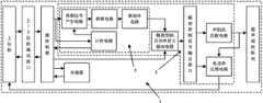
图1为本发明超声相控阵列聚焦模式高速切换系统的系统组成框图;Fig. 1 is a system composition block diagram of the ultrasonic phased array focus mode high-speed switching system of the present invention;
图2为本发明的系统工作流程图;Fig. 2 is a system work flowchart of the present invention;
图中:1为超声相控阵列聚焦模式高速切换系统,2为幅相控制信号发生器,3为相控信号发生器。In the figure: 1 is the high-speed switching system of ultrasonic phased array focus mode, 2 is the amplitude and phase control signal generator, and 3 is the phase control signal generator.
具体实施方式Detailed ways
下面结合具体实施例对本发明进行详细说明。以下实施例将有助于本领域的技术人员进一步理解本发明,但不以任何形式限制本发明。应当指出的是,对本领域的普通技术人员来说,在不脱离本发明构思的前提下,还可以做出若干变形和改进。这些都属于本发明的保护范围。The present invention will be described in detail below in conjunction with specific embodiments. The following examples will help those skilled in the art to further understand the present invention, but do not limit the present invention in any form. It should be noted that those skilled in the art can make several modifications and improvements without departing from the concept of the present invention. These all belong to the protection scope of the present invention.
请参阅图1,一种超声相控阵列聚焦模式高速切换系统1,包括:上位机、上/下位机通讯接口、微控制器、存储器、幅相控制信号发生器2和超声相控阵列,微控制器通过上/下位机通讯接口与上位机连接,存储器与微控制器连接,幅相控制信号发生器2分别与微控制器、上位机和超声相控阵列连接,微控制器通过上/下位机通讯接口与上位机进行数据接收和发送,同时将相关数据存入存储器,当微控制器接收到上位机发送的控制命令,随即取出存储器内相关数据,并将相关数据发送至幅相控制信号发生器2,幅相控制信号发生器2根据接收到的数据产生合成聚焦模式或高速切换不同聚焦模式所需的多路正弦波信号,并发送至超声相控阵列激励超声相控阵列内对应阵元。Please refer to Fig. 1, a high-speed switching system 1 of ultrasonic phased array focus mode, including: upper computer, upper/lower computer communication interface, microcontroller, memory, amplitude and phase control signal generator 2 and ultrasonic phased array, micro The controller is connected to the host computer through the upper/lower computer communication interface, the memory is connected to the microcontroller, the amplitude and phase control signal generator 2 is respectively connected to the microcontroller, the upper computer and the ultrasonic phased array, and the microcontroller is connected through the upper/lower bit The computer communication interface receives and sends data with the upper computer, and stores the relevant data in the memory at the same time. When the microcontroller receives the control command sent by the upper computer, it immediately takes out the relevant data in the memory and sends the relevant data to the amplitude and phase control signal. Generator 2, amplitude and phase control signal generator 2 generates multiple sine wave signals required for synthesizing the focus mode or switching between different focus modes at high speed according to the received data, and sends them to the ultrasonic phased array to excite the corresponding array in the ultrasonic phased array Yuan.
幅相控制信号发生器2至少包括相控信号发生器3、幅度控制及功率放大驱动电路、幅相控制信号输出接口、超声相控阵列内对应阵元的声阻抗匹配电路和电功率反馈电路,相控信号发生器用以接收微控制器发出的激励正弦波信号的相位信息、输出开启时间和输出停止时间并进行相应的处理,且当单组聚焦模式对应激励正弦波信号的总输出时间结束后,相控信号发生器将输出结束反馈信息发送至微控制器;幅度控制及功率放大驱动电路用以接收微控制器发出的激励正弦波信号的幅度信息;电功率反馈电路与上位机连接,用以将超声相控阵列内对应阵元正弦波信号的电功率反馈发送至上位机。The amplitude and phase control signal generator 2 at least includes a phase
相控信号发生器3进一步包括周期信号产生电路、相移电路、计时电路和用以实现激励信号的相位与设定信号相位同步并减小两者相位间误差的锁相环电路。周期信号产生电路、相移电路和锁相环电路依次连接,周期信号产生电路与微控制器连接,锁相环电路与幅度控制及功率放大驱动电路连接,计时电路分别与微控制器和周期信号产生电路连接。The phase
具体地,微控制器通过上/下位机通讯接口与上位机进行传输的数据包括接收部分和发送部分,其中,接收部分至少包括聚焦模式信息和控制命令信息,聚焦模式信息至少包括各组聚焦模式对应的序号、焦点三维坐标以及超声相控阵列激励正弦波信号的幅度和相位;控制命令信息至少包括开启或停止输出激励正弦波信号指令、各组聚焦模式对应的焦点三维坐标、激励正弦波信号的输出开启时间和输出停止时间;发送部分至少包括各组聚焦模式对应激励正弦波信号的反馈信息,该信息至少包括单组聚焦模式对应激励正弦波信号的输出结束反馈信息。Specifically, the data transmitted between the microcontroller and the host computer through the upper/lower computer communication interface includes a receiving part and a sending part, wherein the receiving part includes at least focus mode information and control command information, and the focus mode information includes at least each group of focus mode information. Corresponding serial numbers, three-dimensional coordinates of the focal point, and the amplitude and phase of the ultrasonic phased array excitation sine wave signal; the control command information includes at least the command to start or stop outputting the excitation sine wave signal, the three-dimensional coordinates of the focal point corresponding to each group of focus modes, and the excitation sine wave signal The output start time and output stop time; the sending part at least includes the feedback information of the excitation sine wave signal corresponding to each group of focus modes, and the information at least includes the output end feedback information of the excitation sine wave signal corresponding to the single focus mode.
进一步地,微控制器存入存储器的相关数据至少包括聚焦模式信息,聚焦模式信息至少包括各组聚焦模式对应的序号、焦点三维坐标以及超声相控阵列激励正弦波信号的幅度和相位;根据控制命令信息中各组聚焦模式对应的焦点三维坐标,微控制器从存储器内取出对应的相关数据,至少包括各组聚焦模式对应的超声相控阵列激励正弦波信号的幅度和相位。Further, the relevant data stored in the memory by the microcontroller includes at least focus mode information, and the focus mode information includes at least the serial number corresponding to each group of focus modes, the three-dimensional coordinates of the focus, and the amplitude and phase of the ultrasonic phased array excitation sine wave signal; according to the control For the three-dimensional coordinates of the focal point corresponding to each group of focusing modes in the command information, the microcontroller retrieves the corresponding relevant data from the memory, at least including the amplitude and phase of the ultrasonic phased array excitation sine wave signal corresponding to each group of focusing modes.
本实例中,需要说明的是,微控制器或存储器既可以是独立于相控信号发生器的真实的微控制器或存储器,也可以是与相控信号发生器共同集成在现场可编程门阵列芯片上且采用其资源构建的虚拟的微控制器或存储器。并且,存储器可至少存储三组不同聚焦模式信息的数据。In this example, it should be noted that the microcontroller or memory can be a real microcontroller or memory independent of the phase control signal generator, or it can be integrated with the phase control signal generator in a field programmable gate array A virtual microcontroller or memory built on a chip and using its resources. Also, the memory can store at least three sets of data of different focus mode information.
超声相控阵列为一维、二维或三维阵列;阵列内阵元形状不局限于圆形、方形或菱形;阵列内阵元尺寸相同,或不尽相同;列内相邻阵元间距相同,或不尽相同。Ultrasonic phased arrays are one-dimensional, two-dimensional or three-dimensional arrays; the shape of the array elements is not limited to circular, square or rhombus; the array elements in the array have the same or different dimensions; the distance between adjacent elements in the column is the same, or not quite the same.
本发明的系统用以产生合成单组聚焦模式所需的64~512路正弦波激励信号,正弦波激励信号为连续波信号或脉冲波信号;产生单组聚焦模式合成的多路正弦波信号的耗时与超声相控阵列的阵元数目成正比,且耗时不超过10毫秒。The system of the present invention is used to generate 64-512 channels of sine wave excitation signals required for synthesizing single-group focus modes, and the sine-wave excitation signals are continuous wave signals or pulse wave signals; The time consumption is proportional to the number of array elements of the ultrasonic phased array, and the time consumption does not exceed 10 milliseconds.
在本发明的一个实施例中,超声相控阵列由128个阵元组成,合成单组聚焦模式则须产生128路激励正弦波信号。上位机采用自带多个串/并行接口和USB接口的工控机,微控制器是独立于相控信号发生器的真实微控制器,采用MCS-51系列单片机,上/下位机通讯接口采用串/并行接口,存储器是独立于相控信号发生器的真实存储器,采用Cypress半导体公司的静态RAM芯片(CY62182BN),该芯片容量为1Mbit(128K*8bit),地址线为16位,数据线为8位,可被MCS-51系列单片机读写。相控信号发生器3中,根据阵元谐振频率,周期信号产生电路中除信号源采用石英晶体振荡器外,周期信号产生电路其余部分、相移电路、锁相环电路和计时电路均集成在现场可编程门阵列芯片上,采用Altera公司的FPGA芯片(Cyclone III EP3C40F484C8),该芯片具有331个外部独立I/O,满足了128路信号的输出要求,锁相环输出频率最高可达402MHz,满足了128倍频(假设阵元谐振频率即基频为2MHz)的需求,幅度控制及功率放大驱动电路采用附带电源的变压器耦合乙类推挽式功率放大器电路,幅相控制信号输出接口采用同轴电缆连接器接口。针对各阵元自身阻抗特性,声阻抗匹配电路采用LC(电感电容)阻抗匹配电路,电功率反馈电路如下:将Agilent示波器的电压探头和电流探头分别置于幅相控制信号输出接口和同轴电缆上测量激励正弦波信号的电压和电流,示波器随后将两者有效值的乘积(即电功率)采用USB传输方式发送至上位机。In an embodiment of the present invention, the ultrasonic phased array is composed of 128 array elements, and 128 excitation sine wave signals must be generated to synthesize a single focus mode. The upper computer adopts an industrial computer with multiple serial/parallel interfaces and USB interfaces. The microcontroller is a real microcontroller independent of the phase control signal generator. It adopts MCS-51 series single-chip microcomputers. /parallel interface, the memory is a real memory independent of the phase control signal generator, using the static RAM chip (CY62182BN) of Cypress Semiconductor Company, the chip capacity is 1Mbit (128K*8bit), the address line is 16 bits, and the data line is 8 Bits, can be read and written by MCS-51 series MCU. In the phase-controlled
请参阅图2,其为本发明的超声相控阵列聚焦模式高速切换系统的工作流程图。基于上述的超声相控阵列聚焦模式高速切换系统1,本发明还提供一种基于上述的超声相控阵列聚焦模式高速切换系统的聚焦模式合成方法,根据单组聚焦模式的焦点三维坐标和超声相控阵列内各阵元之间的几何关系以及焦点处设定声压的复数向量,采用伪逆矩阵方法或纯相位激励方法求出对应的超声相控阵列内各阵元激励正弦波信号的幅度和相位,具体包括以下步骤:Please refer to FIG. 2 , which is a working flow chart of the high-speed switching system of the ultrasonic phased array focus mode of the present invention. Based on the above-mentioned ultrasonic phased array focus mode high-speed switching system 1, the present invention also provides a focusing mode synthesis method based on the above-mentioned ultrasonic phased array focus mode high-speed switching system. According to the geometric relationship between the array elements in the ultrasonic phased array and the complex number vector of the sound pressure at the focal point, use the pseudo inverse matrix method or the pure phase excitation method to obtain the amplitude of the corresponding excitation sine wave signal of each array element in the ultrasonic phased array and phase, specifically including the following steps:
第一步,初步确定上位机的发送数据,包括各组聚焦模式对应的序号、焦点三维坐标以及激励正弦波信号的输出开启时间和输出停止时间。The first step is to preliminarily determine the sending data of the host computer, including the serial numbers corresponding to each group of focus modes, the three-dimensional coordinates of the focus, and the output start time and output stop time of the excitation sine wave signal.
第二步,通过聚焦模式合成方法进一步确定上位机的发送数据,包括各组聚焦模式对应超声相控阵列激励正弦波信号的幅度和相位。The second step is to further determine the sending data of the host computer through the focus mode synthesis method, including the amplitude and phase of the ultrasonic phased array excitation sine wave signal corresponding to each group of focus modes.
第三步,经上/下位机通讯接口,上位机将聚焦模式信息发送至微控制器,该信息至少包括各组聚焦模式对应的序号、焦点三维坐标以及超声相控阵列激励正弦波信号的幅度和相位,微控制器随后将该数据存入存储器。In the third step, the upper computer sends the focus mode information to the microcontroller through the upper/lower computer communication interface. The information includes at least the serial numbers corresponding to each group of focus modes, the three-dimensional coordinates of the focus, and the amplitude of the sine wave signal excited by the ultrasonic phased array and phase, the microcontroller then stores this data into memory.
第四步,经上/下位机通讯接口,上位机将控制命令信息发送至微控制器,该信息至少包括开启或停止输出激励正弦波信号指令、各组聚焦模式对应的焦点三维坐标、激励正弦波信号的输出开启时间和输出停止时间,根据控制命令信息中各组聚焦模式对应的焦点三维坐标,微控制器从存储器内取出对应的相关数据,至少包括各组聚焦模式对应的超声相控阵列激励正弦波信号的幅度和相位。Step 4: Through the upper/lower computer communication interface, the upper computer sends the control command information to the microcontroller. The information includes at least the command to start or stop outputting the excitation sine wave signal, the three-dimensional coordinates of the focal point corresponding to each group of focus modes, and the excitation sine wave signal. Wave signal output start time and output stop time, according to the focus three-dimensional coordinates corresponding to each group of focus modes in the control command information, the microcontroller fetches the corresponding relevant data from the memory, including at least the ultrasonic phased array corresponding to each group of focus modes Amplitude and phase of the excitation sine wave signal.
第五步,微控制器将激励正弦波信号的相位信息、输出开启时间和输出停止时间发送至相控信号发生器,同时将幅度信息发送至幅度控制及功率放大驱动电路。In the fifth step, the microcontroller sends the phase information, output start time and output stop time of the excitation sine wave signal to the phase control signal generator, and sends the amplitude information to the amplitude control and power amplification driving circuit.
第六步,幅相控制信号发生器接收到通过上位机计算得到的激励正弦波信号的相位和幅度,产生相应激励正弦波信号,并输出激励正弦波信号至超声相控阵列内对应阵元,同时相控信号发生器对该激励信号的输出总时间进行计时,电功率反馈电路将超声相控阵列内对应阵元正弦波信号的电功率反馈发送至上位机,当该组聚焦模式对应激励正弦波信号的总输出时间结束后,相控信号发生器将输出结束反馈发送至微控制器,微控制器将该反馈发送至上位机,之后将下一组聚焦模式对应激励正弦波信号的相关信息发送至相控信号发生器和幅度控制及功率放大驱动电路,进而实现相邻聚焦模式的高速切换,重复第六步直至完成各组聚焦模式的合成和切换。In the sixth step, the amplitude and phase control signal generator receives the phase and amplitude of the excitation sine wave signal calculated by the host computer, generates the corresponding excitation sine wave signal, and outputs the excitation sine wave signal to the corresponding array element in the ultrasonic phased array, At the same time, the phase control signal generator will time the total output time of the excitation signal, and the electric power feedback circuit will send the electric power feedback corresponding to the sine wave signal of the array element in the ultrasonic phase control array to the host computer. When the group of focus modes corresponds to the excitation sine wave signal After the total output time is over, the phase control signal generator will send the output end feedback to the microcontroller, and the microcontroller will send the feedback to the host computer, and then send the relevant information of the excitation sine wave signal corresponding to the next group of focus modes to the The phase control signal generator and the amplitude control and power amplification drive circuit realize the high-speed switching of adjacent focus modes, and repeat the sixth step until the synthesis and switching of each group of focus modes is completed.
步骤六中,上位机计算得到激励正弦波信号的相位和幅度的步骤具体为:合成单组聚焦模式须求出对应相控阵列内各阵元激励正弦波信号的幅度和相位,假设该相控阵列由N个阵元组成且该组聚焦模式包括M个焦点,则设焦点处设定声压的复数矩阵定义为pM*1,其中,下标表示矩阵的行数(M)和列数(1),根据焦点三维坐标和超声相控阵列内各阵元之间的几何关系可确定一前向传递算子,用矩阵HM*N表示,该组聚焦模式对应激励正弦波信号的复数向量为uN*1,以上三者关系为:pM*1=HM*NuN*1。以下将pM*1、HM*N和uN*1分别简写为p、H和u,即三者关系为:p=Hu,u包含幅度和相位的信息,u=A×ejθ,其中,A表示幅度,θ表示相位,×表示向量间对应位置复数的乘法运算,j表示虚数单位;采用伪逆矩阵方法适用于合成多焦点聚焦模式,则H为矩阵;采用纯相位激励方法适用于合成单焦点聚焦模式,则H为向量;其中,In step six, the host computer calculates the phase and amplitude of the excitation sine wave signal specifically as follows: the amplitude and phase of the excitation sine wave signal of each array element in the corresponding phased array must be obtained for synthesizing a single-group focusing mode, assuming that the phase control The array is composed of N array elements and the group of focus modes includes M focal points, then the complex matrix of the set sound pressure at the focal point is defined as pM*1 , where the subscript represents the number of rows (M) and columns of the matrix (1), according to the three-dimensional coordinates of the focal point and the geometric relationship between the elements in the ultrasonic phased array, a forward transfer operator can be determined, represented by the matrix HM*N , and this group of focusing modes corresponds to the complex number of the excitation sine wave signal The vector is uN*1 , and the relationship between the above three is: pM*1 =HM*N uN*1 . In the following, pM*1 , HM*N , and uN*1 are abbreviated as p, H, and u respectively, that is, the relationship between the three is: p=Hu, u contains the information of amplitude and phase, u=A×ejθ , Among them, A represents the amplitude, θ represents the phase, × represents the multiplication operation of the complex number corresponding to the position between the vectors, and j represents the imaginary number unit; the pseudo-inverse matrix method is suitable for the synthetic multi-focus focusing mode, and H is a matrix; the pure phase excitation method is suitable In the synthetic single focus mode, then H is a vector; where,
伪逆矩阵方法为:u=H+p,The pseudo-inverse matrix method is: u=H+ p,
H+是H的伪逆,H+=H*t(HH*t)-1,其中,上标*表示矩阵共轭,上标t表示矩阵转置,上标-1表示矩阵求逆;H+ is the pseudo-inverse of H, H+ =H*t (HH*t )-1 , where the superscript * indicates matrix conjugation, superscript t indicates matrix transposition, and superscript -1 indicates matrix inversion;
纯相位激励方法为:θ=arg(H*t)+arg(p),The pure phase excitation method is: θ=arg(H*t )+arg(p),
A=abs(p)/dot(H,ejθ),A=abs(p)/dot(H,ejθ ),
u=A×ejθ,u=A×ejθ ,
其中,arg表示对向量取幅角,abs表示对向量取模,dot表示两向量的点积。Among them, arg means taking the argument of the vector, abs means taking the modulus of the vector, and dot means the dot product of two vectors.
本发明利用上位机发送一次控制命令至微控制器即可依次完成多组设定聚焦模式的合成与切换,无需与幅相控制信号发生器直接通讯,大幅提高了数据传输速度,实现了聚焦模式间的高速切换,且在系统内设计了反馈模块,实现了超声相控阵列内各阵元激励信号与设定正弦波信号的同步。本发明可用于医学成像系统引导的相控型聚焦超声系统中聚焦模式合成或多个聚焦模式间高速切换。The present invention uses the host computer to send a control command to the microcontroller to complete the combination and switching of multiple set focus modes in sequence, without direct communication with the amplitude and phase control signal generator, greatly improving the data transmission speed and realizing the focus mode The high-speed switching between them, and the feedback module is designed in the system, which realizes the synchronization of the excitation signal of each array element in the ultrasonic phased array and the set sine wave signal. The present invention can be used for focusing mode synthesis or high-speed switching between multiple focusing modes in a phase-controlled focused ultrasound system guided by a medical imaging system.
以上对本发明的具体实施例进行了描述。需要理解的是,本发明并不局限于上述特定实施方式,本领域技术人员可以在权利要求的范围内做出各种变形或修改,这并不影响本发明的实质内容。Specific embodiments of the present invention have been described above. It should be understood that the present invention is not limited to the specific embodiments described above, and those skilled in the art may make various changes or modifications within the scope of the claims, which do not affect the essence of the present invention.
Claims (11)
Priority Applications (1)
| Application Number | Priority Date | Filing Date | Title |
|---|---|---|---|
| CN201310093642.6ACN103191528B (en) | 2013-03-21 | 2013-03-21 | Ultrasonic phased array focusing mode high-speed switching system and focusing mode synthetic method |
Applications Claiming Priority (1)
| Application Number | Priority Date | Filing Date | Title |
|---|---|---|---|
| CN201310093642.6ACN103191528B (en) | 2013-03-21 | 2013-03-21 | Ultrasonic phased array focusing mode high-speed switching system and focusing mode synthetic method |
Publications (2)
| Publication Number | Publication Date |
|---|---|
| CN103191528Atrue CN103191528A (en) | 2013-07-10 |
| CN103191528B CN103191528B (en) | 2015-10-14 |
Family
ID=48714452
Family Applications (1)
| Application Number | Title | Priority Date | Filing Date |
|---|---|---|---|
| CN201310093642.6AActiveCN103191528B (en) | 2013-03-21 | 2013-03-21 | Ultrasonic phased array focusing mode high-speed switching system and focusing mode synthetic method |
Country Status (1)
| Country | Link |
|---|---|
| CN (1) | CN103191528B (en) |
Cited By (7)
| Publication number | Priority date | Publication date | Assignee | Title |
|---|---|---|---|---|
| CN105686852A (en)* | 2014-11-24 | 2016-06-22 | 深圳大学 | Ophthalmology diagnosis-based ultrasonic pulse excitation and echo acquisition system |
| CN107863097A (en)* | 2017-11-28 | 2018-03-30 | 华中科技大学 | A kind of method based on patterning tailoring technique focused sound waves |
| CN108062948A (en)* | 2017-11-28 | 2018-05-22 | 华中科技大学 | A kind of method based on patterning tailoring technique regulation and control sound wave |
| CN108062947A (en)* | 2017-11-28 | 2018-05-22 | 华中科技大学 | A kind of method being vortexed based on patterning tailoring technique formation sound |
| CN114047256A (en)* | 2021-10-25 | 2022-02-15 | 扬州大学 | Ultrasonic imaging method for defects of flat ceramic membrane based on dynamic array element synthetic aperture focusing |
| WO2023035503A1 (en)* | 2021-09-08 | 2023-03-16 | 中惠医疗科技(上海)有限公司 | Multi-channel ultrasonic drive circuit having phase-controlled focus and multi-channel ultrasonic therapeutic apparatus |
| CN118170058A (en)* | 2024-02-02 | 2024-06-11 | 沈阳长江源科技发展有限公司 | Spherical focusing ultrasonic transducer control system, method, terminal and treatment equipment |
Citations (3)
| Publication number | Priority date | Publication date | Assignee | Title |
|---|---|---|---|---|
| CN1883397A (en)* | 2005-06-20 | 2006-12-27 | 株式会社东芝 | Ultrasonic diagnosis device and ultrasonic metering method |
| CN101862511A (en)* | 2010-05-07 | 2010-10-20 | 上海交通大学 | Multi-channel high precision phase control signal generator |
| US20110054315A1 (en)* | 2009-08-26 | 2011-03-03 | Roberts William W | Micromanipulator control arm for therapeutic and imaging ultrasound transducers |
- 2013
- 2013-03-21CNCN201310093642.6Apatent/CN103191528B/enactiveActive
Patent Citations (3)
| Publication number | Priority date | Publication date | Assignee | Title |
|---|---|---|---|---|
| CN1883397A (en)* | 2005-06-20 | 2006-12-27 | 株式会社东芝 | Ultrasonic diagnosis device and ultrasonic metering method |
| US20110054315A1 (en)* | 2009-08-26 | 2011-03-03 | Roberts William W | Micromanipulator control arm for therapeutic and imaging ultrasound transducers |
| CN101862511A (en)* | 2010-05-07 | 2010-10-20 | 上海交通大学 | Multi-channel high precision phase control signal generator |
Cited By (11)
| Publication number | Priority date | Publication date | Assignee | Title |
|---|---|---|---|---|
| CN105686852A (en)* | 2014-11-24 | 2016-06-22 | 深圳大学 | Ophthalmology diagnosis-based ultrasonic pulse excitation and echo acquisition system |
| CN107863097A (en)* | 2017-11-28 | 2018-03-30 | 华中科技大学 | A kind of method based on patterning tailoring technique focused sound waves |
| CN108062948A (en)* | 2017-11-28 | 2018-05-22 | 华中科技大学 | A kind of method based on patterning tailoring technique regulation and control sound wave |
| CN108062947A (en)* | 2017-11-28 | 2018-05-22 | 华中科技大学 | A kind of method being vortexed based on patterning tailoring technique formation sound |
| CN108062948B (en)* | 2017-11-28 | 2020-07-10 | 华中科技大学 | A method for regulating sound waves based on pattern cutting technology |
| CN108062947B (en)* | 2017-11-28 | 2021-06-29 | 华中科技大学 | A method for forming acoustic vortex based on pattern cutting technology |
| CN107863097B (en)* | 2017-11-28 | 2021-07-02 | 华中科技大学 | A method of focusing sound waves based on patterned cutting technology |
| WO2023035503A1 (en)* | 2021-09-08 | 2023-03-16 | 中惠医疗科技(上海)有限公司 | Multi-channel ultrasonic drive circuit having phase-controlled focus and multi-channel ultrasonic therapeutic apparatus |
| CN114047256A (en)* | 2021-10-25 | 2022-02-15 | 扬州大学 | Ultrasonic imaging method for defects of flat ceramic membrane based on dynamic array element synthetic aperture focusing |
| CN114047256B (en)* | 2021-10-25 | 2023-10-20 | 扬州大学 | Flat ceramic membrane defect ultrasonic imaging method based on dynamic array element synthetic aperture focusing |
| CN118170058A (en)* | 2024-02-02 | 2024-06-11 | 沈阳长江源科技发展有限公司 | Spherical focusing ultrasonic transducer control system, method, terminal and treatment equipment |
Also Published As
| Publication number | Publication date |
|---|---|
| CN103191528B (en) | 2015-10-14 |
Similar Documents
| Publication | Publication Date | Title |
|---|---|---|
| CN103191528B (en) | Ultrasonic phased array focusing mode high-speed switching system and focusing mode synthetic method | |
| US11914079B2 (en) | Architecture of single substrate ultrasonic imaging devices, related apparatuses, and methods | |
| Marzo et al. | Ultraino: An open phased-array system for narrowband airborne ultrasound transmission | |
| US11137486B2 (en) | Parameter loader for ultrasound probe and related apparatus and methods | |
| CN109031435B (en) | NMR groundwater directional detection system and detection method based on phased array | |
| CA3018870A1 (en) | Serial interface for parameter transfer in an ultrasound device | |
| JP4638622B2 (en) | Real-time 3D ultrasound imaging device and probe | |
| JP5552062B2 (en) | Ultrasonic diagnostic equipment | |
| Zheng et al. | Multi-channel drive system of phased array based on DDS chips | |
| KR102834454B1 (en) | High-speed distribution of data for control of ultrasonic devices | |
| WO2005027747A1 (en) | Ultrasonic diagnosis apparatus | |
| JP2005131409A (en) | Method and device for transducer probe | |
| CN114089282B (en) | Digital beam processing method based on software radar | |
| CN112199899B (en) | Single-source generation method and generation device for orbital angular momentum in two-dimensional fluctuation system | |
| CN114326508B (en) | Ultrasonic phased array timing control method and device, ultrasonic equipment | |
| WO2017026019A1 (en) | Ultrasonic imaging device and ultrasonic probe | |
| CN117507369A (en) | A 3D printing method and system based on ultrasonic phase control technology | |
| JP2014121478A (en) | Ultrasonic diagnostic apparatus | |
| JP2003116851A (en) | Wide angle directional ultrasonic beam forming method and device |
Legal Events
| Date | Code | Title | Description |
|---|---|---|---|
| C06 | Publication | ||
| PB01 | Publication | ||
| C10 | Entry into substantive examination | ||
| SE01 | Entry into force of request for substantive examination | ||
| C14 | Grant of patent or utility model | ||
| GR01 | Patent grant | ||
| TR01 | Transfer of patent right | ||
| TR01 | Transfer of patent right | Effective date of registration:20250110 Address after:200233, 1st and 4th floors, Building 8, No. 1001 Qinzhou North Road, Xuhui District, Shanghai Patentee after:Shanghai Shende Wuchuang Era Medical Technology Co.,Ltd. Country or region after:China Address before:200240 No. 800, Dongchuan Road, Shanghai, Minhang District Patentee before:SHANGHAI JIAO TONG University Country or region before:China |