CN103184142A - Light biological reaction equipment and light biological culture method - Google Patents
Light biological reaction equipment and light biological culture methodDownload PDFInfo
- Publication number
- CN103184142A CN103184142ACN201110449620XACN201110449620ACN103184142ACN 103184142 ACN103184142 ACN 103184142ACN 201110449620X ACN201110449620X ACN 201110449620XACN 201110449620 ACN201110449620 ACN 201110449620ACN 103184142 ACN103184142 ACN 103184142A
- Authority
- CN
- China
- Prior art keywords
- photobioreactor
- container
- photobiological
- heat
- heat preservation
- Prior art date
- Legal status (The legal status is an assumption and is not a legal conclusion. Google has not performed a legal analysis and makes no representation as to the accuracy of the status listed.)
- Pending
Links
- 238000006243chemical reactionMethods0.000titleclaimsabstractdescription17
- 238000012136culture methodMethods0.000title1
- 238000004321preservationMethods0.000claimsabstractdescription59
- 230000000258photobiological effectEffects0.000claimsabstractdescription58
- 239000007788liquidSubstances0.000claimsabstractdescription18
- 238000009413insulationMethods0.000claimsdescription21
- 239000012531culture fluidSubstances0.000claimsdescription11
- 239000004033plasticSubstances0.000claimsdescription10
- 229920003023plasticPolymers0.000claimsdescription10
- XLYOFNOQVPJJNP-UHFFFAOYSA-NwaterSubstancesOXLYOFNOQVPJJNP-UHFFFAOYSA-N0.000claimsdescription10
- 239000011521glassSubstances0.000claimsdescription9
- 239000000463materialSubstances0.000claimsdescription6
- 239000002184metalSubstances0.000claimsdescription6
- 239000007787solidSubstances0.000claimsdescription3
- 238000012365batch cultivationMethods0.000claimsdescription2
- 239000011449brickSubstances0.000claimsdescription2
- 239000004568cementSubstances0.000claimsdescription2
- 239000000919ceramicSubstances0.000claimsdescription2
- 239000002131composite materialSubstances0.000claimsdescription2
- 230000001788irregularEffects0.000claimsdescription2
- 239000004579marbleSubstances0.000claimsdescription2
- 239000005060rubberSubstances0.000claimsdescription2
- 238000012364cultivation methodMethods0.000claims1
- 238000009395breedingMethods0.000abstractdescription23
- 230000001488breeding effectEffects0.000abstractdescription23
- 230000003287optical effectEffects0.000abstractdescription15
- 238000000034methodMethods0.000abstractdescription3
- 238000012258culturingMethods0.000abstract1
- 239000002609mediumSubstances0.000description18
- 238000005265energy consumptionMethods0.000description8
- 238000005273aerationMethods0.000description7
- 239000012780transparent materialSubstances0.000description5
- 239000001963growth mediumSubstances0.000description4
- 230000000886photobiologyEffects0.000description4
- 238000009423ventilationMethods0.000description4
- 239000004698PolyethyleneSubstances0.000description3
- 238000009826distributionMethods0.000description3
- VVQNEPGJFQJSBK-UHFFFAOYSA-NMethyl methacrylateChemical compoundCOC(=O)C(C)=CVVQNEPGJFQJSBK-UHFFFAOYSA-N0.000description2
- 229920005372Plexiglas®Polymers0.000description2
- 230000010261cell growthEffects0.000description2
- 230000007613environmental effectEffects0.000description2
- 238000002474experimental methodMethods0.000description2
- -1polyethylenePolymers0.000description2
- 229920000573polyethylenePolymers0.000description2
- 238000003756stirringMethods0.000description2
- 241000195493CryptophytaSpecies0.000description1
- 241000224474NannochloropsisSpecies0.000description1
- 239000011358absorbing materialSubstances0.000description1
- 238000010521absorption reactionMethods0.000description1
- 230000000052comparative effectEffects0.000description1
- 238000001816coolingMethods0.000description1
- 239000000498cooling waterSubstances0.000description1
- 238000010586diagramMethods0.000description1
- 230000000694effectsEffects0.000description1
- 238000009313farmingMethods0.000description1
- 230000012010growthEffects0.000description1
- 238000004519manufacturing processMethods0.000description1
- 238000009827uniform distributionMethods0.000description1
Images


Classifications
- C—CHEMISTRY; METALLURGY
- C12—BIOCHEMISTRY; BEER; SPIRITS; WINE; VINEGAR; MICROBIOLOGY; ENZYMOLOGY; MUTATION OR GENETIC ENGINEERING
- C12M—APPARATUS FOR ENZYMOLOGY OR MICROBIOLOGY; APPARATUS FOR CULTURING MICROORGANISMS FOR PRODUCING BIOMASS, FOR GROWING CELLS OR FOR OBTAINING FERMENTATION OR METABOLIC PRODUCTS, i.e. BIOREACTORS OR FERMENTERS
- C12M21/00—Bioreactors or fermenters specially adapted for specific uses
- C12M21/02—Photobioreactors
- C—CHEMISTRY; METALLURGY
- C12—BIOCHEMISTRY; BEER; SPIRITS; WINE; VINEGAR; MICROBIOLOGY; ENZYMOLOGY; MUTATION OR GENETIC ENGINEERING
- C12M—APPARATUS FOR ENZYMOLOGY OR MICROBIOLOGY; APPARATUS FOR CULTURING MICROORGANISMS FOR PRODUCING BIOMASS, FOR GROWING CELLS OR FOR OBTAINING FERMENTATION OR METABOLIC PRODUCTS, i.e. BIOREACTORS OR FERMENTERS
- C12M23/00—Constructional details, e.g. recesses, hinges
- C12M23/20—Material Coatings
- C—CHEMISTRY; METALLURGY
- C12—BIOCHEMISTRY; BEER; SPIRITS; WINE; VINEGAR; MICROBIOLOGY; ENZYMOLOGY; MUTATION OR GENETIC ENGINEERING
- C12M—APPARATUS FOR ENZYMOLOGY OR MICROBIOLOGY; APPARATUS FOR CULTURING MICROORGANISMS FOR PRODUCING BIOMASS, FOR GROWING CELLS OR FOR OBTAINING FERMENTATION OR METABOLIC PRODUCTS, i.e. BIOREACTORS OR FERMENTERS
- C12M41/00—Means for regulation, monitoring, measurement or control, e.g. flow regulation
- C12M41/12—Means for regulation, monitoring, measurement or control, e.g. flow regulation of temperature
Landscapes
- Health & Medical Sciences (AREA)
- Life Sciences & Earth Sciences (AREA)
- Engineering & Computer Science (AREA)
- Chemical & Material Sciences (AREA)
- Wood Science & Technology (AREA)
- Zoology (AREA)
- Organic Chemistry (AREA)
- Bioinformatics & Cheminformatics (AREA)
- Biotechnology (AREA)
- Genetics & Genomics (AREA)
- Sustainable Development (AREA)
- Biochemistry (AREA)
- General Engineering & Computer Science (AREA)
- General Health & Medical Sciences (AREA)
- Microbiology (AREA)
- Biomedical Technology (AREA)
- Clinical Laboratory Science (AREA)
- Immunology (AREA)
- Physics & Mathematics (AREA)
- Thermal Sciences (AREA)
- Analytical Chemistry (AREA)
- Molecular Biology (AREA)
- Apparatus Associated With Microorganisms And Enzymes (AREA)
Abstract
Translated fromChinese
Description
Translated fromChinese技术领域technical field
本发明涉及一种光生物反应设备。The invention relates to a photobiological reaction device.
背景技术Background technique
在现有技术中,有两种光生物反应器,一种是光程(该处光程表示为光生物反应器的光程即光生物反应器的宽度:从光生物反应器的一个侧壁(受光面)到相对的另一个侧壁(受光面)的距离)较短的短光程反应器,一种是光程较长的宽光程反应器。In the prior art, there are two kinds of photobioreactors, one is the light path (the light path here is represented as the light path of the photobioreactor, which is the width of the photobioreactor: from one side wall of the photobioreactor (the distance from the light-receiving surface) to the opposite side wall (light-receiving surface)) is a short optical path reactor, and one is a wide optical path reactor with a longer optical path.
对于短光程反应器,由于其宽度小、光程短,因此光射入培养液充分,使光生物反应器内细胞受光充分,最适细胞密度高,可实现光生物(如微藻)高密度养殖,而且由于内部容积小,曝气分布均匀,光生物不易贴壁。但是,由于短光程反应器的内部容积小,能够容纳的光生物培养液的体积小,因此热容量低,户外养殖时,温度上升快,易造成养殖温度过高,导致藻细胞死亡。For the short photopath reactor, due to its small width and short photopath, the light is fully injected into the culture medium, so that the cells in the photobioreactor are fully exposed to light, and the optimal cell density is high, which can realize high photobiology (such as microalgae). Density farming, and because of the small internal volume and uniform distribution of aeration, photobiology is not easy to adhere to the wall. However, due to the small internal volume of the short photopath reactor, the volume of the photobiological culture solution that can be accommodated is small, so the heat capacity is low. When the outdoor culture is performed, the temperature rises rapidly, which easily causes the culture temperature to be too high, resulting in the death of algae cells.
对于宽光程反应器,由于其宽度大、光程长,因此,内部容积较大,能够容纳的光生物培养液的体积就较大,因此热容量大,温度上升速度慢,温度易控制。但是,由于其宽度大、光程长,因此光射入培养液不充分,使光生物反应器内细胞受光不充分,养殖最适细胞密度低,养殖效率低;由于内部容积大,易造成曝气分布不均,同时光生物易贴壁。另外,为增加光反应器内细胞受光频率,提高光的利用效率,需加大曝气量,使曝气能耗增大。For the wide optical path reactor, due to its large width and long optical path, the internal volume is larger, and the volume of the photobiological culture solution that can be accommodated is larger, so the heat capacity is large, the temperature rises slowly, and the temperature is easy to control. However, due to its large width and long optical path, the light is not injected into the culture medium sufficiently, so that the cells in the photobioreactor are not fully exposed to light, the optimum cell density for cultivation is low, and the cultivation efficiency is low; due to the large internal volume, it is easy to cause exposure. The gas distribution is uneven, and photobiology is easy to adhere to the wall. In addition, in order to increase the light receiving frequency of the cells in the photoreactor and improve the light utilization efficiency, it is necessary to increase the amount of aeration to increase the energy consumption of the aeration.
发明内容Contents of the invention
本发明提供一种光生物反应设备,其不仅热容量大,能够实现稳定的养殖温度,而且通气能耗低,曝气分布均一,可改善贴壁状况。The invention provides a photobiological reaction device, which not only has a large heat capacity, can realize a stable breeding temperature, but also has low ventilation energy consumption, uniform aeration distribution, and can improve the wall-attachment condition.
根据本发明的一个方面,提供一种光生物反应设备,包括:至少一个光生物反应器,在所述光生物反应器中容纳有光生物培养液;和至少一个保温容器,在所述保温容器中容纳有吸热介质。其中,所述保温容器设置成与光生物反应器的侧壁接触或直接与光生物反应器内的光生物培养液接触,以便在光生物培养液和吸热介质之间进行热交换,所述光生物反应器的侧壁和与其相邻但不接触的所述保温容器的侧壁之间的距离在0.5cm至50cm的范围内。优选地,在1cm至25cm的范围内。According to one aspect of the present invention, a kind of photobioreactor equipment is provided, comprising: at least one photobioreactor, photobioreactor is contained in the photobioreactor; and at least one heat preservation container, in the heat preservation container A heat absorbing medium is contained in it. Wherein, the heat preservation container is arranged to be in contact with the side wall of the photobioreactor or directly in contact with the photobiological culture liquid in the photobioreactor, so as to perform heat exchange between the photobiological culture liquid and the heat-absorbing medium, and the The distance between the side wall of the photobioreactor and the side wall of the heat preservation container adjacent to but not in contact with it is in the range of 0.5 cm to 50 cm. Preferably, in the range of 1 cm to 25 cm.
根据本发明的一个优选实施例,所述光生物反应器和/或所述保温容器为长方体形容器、类似长方体的不规则容器、或横截面为圆形或梯形的容器。优选地,所述光生物反应器和所述保温容器均为长方体形容器。According to a preferred embodiment of the present invention, the photobioreactor and/or the heat preservation container is a rectangular parallelepiped container, an irregular container similar to a rectangular parallelepiped, or a circular or trapezoidal container in cross section. Preferably, both the photobioreactor and the heat preservation container are rectangular parallelepiped containers.
根据本发明的另一个优选实施例,所述保温容器直接放置在所述光生物反应器中,并且所述保温容器的底面、侧面与所述光生物反应器的至少一个面不接触。According to another preferred embodiment of the present invention, the heat preservation container is directly placed in the photobioreactor, and the bottom surface and the side surface of the heat preservation container are not in contact with at least one surface of the photobioreactor.
根据本发明的另一个优选实施例,所述光生物反应器的端壁和与其相邻的所述保温容器的端壁之间的距离在0.5cm至50cm的范围内。优选地,在1cm至25cm的范围内。According to another preferred embodiment of the present invention, the distance between the end wall of the photobioreactor and the end wall of the adjacent heat preservation container is in the range of 0.5 cm to 50 cm. Preferably, in the range of 1 cm to 25 cm.
根据本发明的另一个优选实施例,所述保温容器放置在两个光生物反应器之间,使得所述保温容器的两个侧壁分别与两个光生物反应器的侧壁接触。According to another preferred embodiment of the present invention, the heat preservation container is placed between two photobioreactors, so that the two side walls of the heat preservation container are respectively in contact with the side walls of the two photobioreactors.
根据本发明的另一个优选实施例,所述光生物反应器依靠在所述保温容器的侧壁上,使得所述光生物反应器的侧壁与所述保温容器的侧壁接触。According to another preferred embodiment of the present invention, the photobioreactor rests on the side wall of the heat preservation container, so that the side wall of the photobioreactor is in contact with the side wall of the heat preservation container.
根据本发明的另一个优选实施例,所述光生物反应器为圆筒形容器,具有外壁和内壁,在所述外壁和所述内壁之间限定第一空间,所述第一空间作为所述光生物反应器,由所述内壁环绕所形成的第二空间作为所述保温容器。According to another preferred embodiment of the present invention, the photobioreactor is a cylindrical container with an outer wall and an inner wall, a first space is defined between the outer wall and the inner wall, and the first space serves as the In the photobioreactor, the second space surrounded by the inner wall is used as the heat preservation container.
根据本发明的另一个优选实施例,所述外壁和内壁之间的距离在1cm至25cm范围内。According to another preferred embodiment of the present invention, the distance between the outer wall and the inner wall is in the range of 1 cm to 25 cm.
根据本发明的另一个优选实施例,所述光生物反应器的侧壁和与其相邻但不接触的所述保温容器的侧壁之间的距离在1cm至20cm的范围内。According to another preferred embodiment of the present invention, the distance between the side wall of the photobioreactor and the side wall of the heat preservation container adjacent to but not in contact with it is in the range of 1 cm to 20 cm.
根据本发明的另一个优选实施例,所述光生物反应器的侧壁和与其相邻但不接触的所述保温容器的侧壁之间的距离在3cm至8cm的范围内。According to another preferred embodiment of the present invention, the distance between the side wall of the photobioreactor and the side wall of the heat preservation container adjacent to but not in contact with it is in the range of 3 cm to 8 cm.
根据本发明的另一个优选实施例,所述吸热介质为液体或固体。According to another preferred embodiment of the present invention, the heat-absorbing medium is liquid or solid.
根据本发明的另一个优选实施例,所述吸热介质为水、金属或其它合适的吸热材料。According to another preferred embodiment of the present invention, the heat-absorbing medium is water, metal or other suitable heat-absorbing materials.
根据本发明的另一个优选实施例,所述光生物反应器由透明材料制成。According to another preferred embodiment of the present invention, the photobioreactor is made of transparent material.
根据本发明的另一个优选实施例,所述光生物反应器由有机玻璃,聚乙烯等塑料或无机质玻璃制成。According to another preferred embodiment of the present invention, the photobioreactor is made of organic glass, plastic such as polyethylene or inorganic glass.
根据本发明的另一个优选实施例,所述保温容器由透明材料或不透明材料制成。According to another preferred embodiment of the present invention, the thermal insulation container is made of transparent material or opaque material.
根据本发明的另一个优选实施例,所述所述保温容器的材料为金属、玻璃、塑料、橡胶、大理石材、复合材料、陶瓷、水泥、砖瓦或其它合适的材料。According to another preferred embodiment of the present invention, the material of the heat preservation container is metal, glass, plastic, rubber, marble, composite material, ceramics, cement, brick or other suitable materials.
本发明还提供一种应用权利要求1的光生物反应设备对光生物进行的批次培养,半连续培养及连续培养方法。The present invention also provides a method for batch cultivation, semi-continuous cultivation and continuous cultivation of photobiology using the photobiological reaction equipment of
在本发明的光生物反应设备中,由于提供了保温容器,通过保温容器内的吸热介质与光生物反应器内的光生物培养液之间进行热交换,从而增大了光生物反应器的热容量,可以利用自然界昼夜环境温度变化与保温容器的吸热放热之间的速度差,实现稳定的养殖温度。同时,能够缩短光穿过光生物培养液的光程,从而可以提高养殖密度和养殖效率。In the photobioreaction equipment of the present invention, since the heat preservation container is provided, heat exchange is performed between the heat-absorbing medium in the heat preservation container and the photobiological culture liquid in the photobioreactor, thereby increasing the temperature of the photobioreactor. The heat capacity can make use of the speed difference between the natural day and night environmental temperature change and the heat absorption and heat release of the heat preservation container to achieve a stable breeding temperature. At the same time, the optical path of light passing through the photobiological culture solution can be shortened, thereby improving the breeding density and breeding efficiency.
附图说明Description of drawings
图1显示根据本发明的第一优选实施例的光生物反应设备的立体示意图;Fig. 1 shows the three-dimensional schematic view of the photobioreactor device according to the first preferred embodiment of the present invention;
图2显示图1所示的光生物反应设备的立体外观图;Fig. 2 shows the three-dimensional appearance diagram of the photobiological reaction equipment shown in Fig. 1;
图3显示根据本发明的第二优选实施例的光生物反应设备的立体示意图;Fig. 3 shows the three-dimensional schematic view of the photobioreactor device according to the second preferred embodiment of the present invention;
图4显示图3所示的光生物反应设备沿高度方向的剖视图;Fig. 4 shows the cross-sectional view of the photobioreaction device shown in Fig. 3 along the height direction;
图5显示根据本发明的第三优选实施例的光生物反应设备的立体示意图;Fig. 5 shows the three-dimensional schematic view of the photobioreactor device according to the third preferred embodiment of the present invention;
图6显示图5所示的光生物反应设备沿高度方向的剖视图;Fig. 6 shows the cross-sectional view of the photobioreaction device shown in Fig. 5 along the height direction;
图7显示根据本发明的第四优选实施例的光生物反应设备的立体示意图;Fig. 7 shows the three-dimensional schematic view of the photobioreactor device according to the fourth preferred embodiment of the present invention;
图8(a)显示第一试验组的反应器;图8(b)显示第二试验组的反应器;图8(c)显示第三试验组的反应器;Figure 8(a) shows the reactor of the first test group; Figure 8(b) shows the reactor of the second test group; Figure 8(c) shows the reactor of the third test group;
图9显示以上三个试验组从2011年8月1日至2011年8月11日的养殖速度比较图;Fig. 9 shows above three test groups from August 1st, 2011 to August 11th, 2011 breeding speed comparison figure;
图10显示以上三个试验组从2011年8月1日至2011年8月11日的日平均养殖速度比较图;Fig. 10 shows above three test groups from August 1, 2011 to August 11, 2011 daily average breeding speed comparison figure;
图11显示以上三个试验组的单位反应器产量比较;Fig. 11 shows the unit reactor output comparison of above three test groups;
图12显示以上三个试验组的反应器在养殖期间单位占地面积日产量变化;和Fig. 12 shows that the reactor of above three test groups changes in the daily output per unit area during cultivation; With
图13显示环境温度(气温)及以上三个试验组的各个反应器的一天中最高温度(PM4:00-5:00)的数据比较。Figure 13 shows the data comparison of the ambient temperature (air temperature) and the maximum temperature (PM4:00-5:00) of each reactor in the above three test groups in a day.
具体实施方式Detailed ways
下面通过实施例,并结合附图,对本发明的技术方案作进一步具体的说明。在说明书中,相同或相似的附图标号指示相同或相似的部件。下述参照附图对本发明实施方式的说明旨在对本发明的总体发明构思进行解释,而不应当理解为对本发明的一种限制。The technical solutions of the present invention will be further specifically described below through the embodiments and in conjunction with the accompanying drawings. In the specification, the same or similar reference numerals designate the same or similar components. The following description of the embodiments of the present invention with reference to the accompanying drawings is intended to explain the general inventive concept of the present invention, but should not be construed as a limitation of the present invention.
[第一实施例][first embodiment]
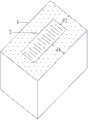
图1显示根据本发明的第一优选实施例的光生物反应设备的立体示意图;和图2显示图1所示的光生物反应设备的立体外观图。Fig. 1 shows a schematic perspective view of a photobioreaction device according to a first preferred embodiment of the present invention; and Fig. 2 shows a perspective view of the photobioreaction device shown in Fig. 1 .
如图1和图2所示,图示的光生物反应设备主要包括一个光生物反应器1和一个保温容器2。As shown in FIG. 1 and FIG. 2 , the illustrated photobioreaction equipment mainly includes a
如图2所示,在光生物反应器1中容纳有光生物培养液,例如,含有微藻的培养液,在保温容器2中容纳有热容量较大的吸热介质,例如,水或其它液体。As shown in Figure 2, the photobiological culture fluid is contained in the
在图1和图2所示的优选实施例中,光生物反应器1和保温容器2均为长方体形容器。但是,请注意,本发明不局限于此,光生物反应器1和保温容器2也可以均为圆筒形容器。In the preferred embodiment shown in Fig. 1 and Fig. 2, both the
请继续参见图1和图2,保温容器2直接放置在光生物反应器1中,并且保温容器2的四壁与光生物反应器1不接触。这样,光生物反应器1中的光生物培养液就能够与保温容器2中的吸热介质例如水或其它液体之间通过保温容器2的四壁进行热交换,从而提高光生物反应器1中的光生物培养液的热容量,保证其温度稳定。例如,在夏季高温环境下养殖微藻时,微藻培养液的温度会升高,通过保温容器2的四壁,可将微藻培养液吸收的太阳光热量及时交换给保温容器2中的吸热介质例如水或其它液体,从而实现光生物反应器1中的微藻培养液温度的稳定控制。Please continue to refer to FIG. 1 and FIG. 2 , the insulated
如图2所示,光生物反应器1的侧壁和与其相邻的保温容器2的侧壁之间的距离d1在1cm至25cm的范围内,这样就能够将光穿过光生物培养液的光程控制在较短的范围内,提高单位体积光生物培养液的光能接收量,从而能够提高养殖效率。但是本发明不局限于此,光生物反应器1的侧壁和与其相邻的保温容器2的侧壁之间的距离d1也可以在0.5cm至50cm的范围内。As shown in Figure 2, the distance d1 between the side wall of
在本发明的另一个优选实施例中,光生物反应器1的侧壁和与其相邻但不接触的保温容器2的侧壁之间的距离d1在2cm至10cm的范围内。更优选地,光生物反应器1的侧壁和与其相邻但不接触的保温容器2的侧壁之间的距离d1在3cm至8cm的范围内。In another preferred embodiment of the present invention, the distance d1 between the side wall of the
在本发明的一个优选实施例中,如图2所示,光生物反应器1的端壁和与其相邻的保温容器2的端壁之间的距离d2在1cm至25cm的范围内。这样不仅保证光生物培养液能够在光生物反应器1的前后两端处连通,而且能够缩短光生物反应器1的前后两端处的光程,提高单位体积光生物培养液的光能接收量,从而能够提高养殖效率。但是,请注意,本发明不局限于图示的实施例,光生物反应器1的端壁和与其相邻的保温容器2的端壁之间的距离d2也可以为零,即,光生物反应器1的端壁和与其相邻的保温容器2的端壁相互接触,之间没有间隙。但是本发明不局限于此,光生物反应器1的端壁和与其相邻的保温容器2的端壁之间的距离d2也可以在0.5cm至50cm的范围内。In a preferred embodiment of the present invention, as shown in FIG. 2 , the distance d2 between the end wall of the
在本发明的另一个优选实施例中,光生物反应器1的端壁和与其相邻的保温容器2的端壁之间的距离d2在2cm至10cm的范围内。更优选地,光生物反应器1的端壁和与其相邻的保温容器2的端壁之间的距离d2在3cm至8cm的范围内。In another preferred embodiment of the present invention, the distance d2 between the end wall of the
在本发明中的其它实施例中,吸热介质除了热容量大的液体外,还可以是热容量大的固体,例如,金属,这样可以在夏天用于制冷。In other embodiments of the present invention, the heat-absorbing medium may be a solid with a large heat capacity, such as metal, in addition to a liquid with a large heat capacity, so that it can be used for cooling in summer.
在本发明中,光生物反应器1由透明材料制成,例如,塑料或玻璃。In the present invention, the
在本发明中,光生物反应器1外壁由透明材料制成,例如,有机玻璃,PE、PP、PA、PVC等塑料或玻璃制成。而内壁可以采用有机玻璃,聚乙烯等塑料或玻璃制成,也可以采用不透明材料。In the present invention, the outer wall of the
在本发明中,光生物反应器1和保温容器2的高度可以相同也可以不同,光生物反应器1中培养液深度与保温容器2中吸热介质高度可以相同也可以不同。In the present invention, the heights of the
在本发明中,在高度方向上,1个光生物反应器1不限于与1个保温容器2配合使用。In the present invention, one
在本发明中,保温容器2可以由透明材料或不透明材料制成,例如,可以由金属、玻璃或塑料制成,这样能够有效提高保温容器2的侧壁的导热性能,提高光生物反应器1内的光生物培养液与保温容器2内的吸热介质之间的热交换效率。In the present invention, the
[第二实施例][Second embodiment]
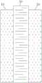
图3显示根据本发明的第二优选实施例的光生物反应设备的立体示意图;和图4显示图3所示的光生物反应设备沿高度方向的剖视图。Fig. 3 shows a schematic perspective view of a photobioreaction device according to a second preferred embodiment of the present invention; and Fig. 4 shows a cross-sectional view of the photobioreaction device shown in Fig. 3 along the height direction.
如图3和图4所示,图示的光生物反应设备主要包括一个保温容器30和两个独立的光生物反应器10、20。在光生物反应器10、20中容纳有光生物培养液,例如,含有微藻的培养液,在保温容器30中容纳有热容量较大的吸热介质,例如,水。As shown in FIG. 3 and FIG. 4 , the illustrated photobioreaction equipment mainly includes a
保温容器30放置在两个光生物反应器10、20之间,使得保温容器30的两个侧壁分别与两个光生物反应器10、20的侧壁接触。这样,光生物反应器10、20中的光生物培养液就能够与保温容器30中的吸热介质之间进行热交换,从而提高光生物反应器10、20中的光生物培养液的热容量,提高其温度稳定性。The
在图3和图4所示的实施例中,光生物反应器10、20和保温容器30均为长方体形容器,容器侧壁间紧密接触,这样,能够增大光生物反应器10、20和保温容器30之间的相互接触面积,提高热交换效率。In the embodiment shown in Fig. 3 and Fig. 4,
请继续参见图3和图4,每个光生物反应器10、20的侧壁和与其相邻但不接触的保温容器30的侧壁之间的距离d1在1cm至25cm的范围内。即,每个光生物反应器10、20的宽度在1cm至25cm的范围内,这样就能够将光穿过光生物培养液的光程控制在较短的范围内,提高了光生物反应器10、20中的单位体积光生物培养液的光能接收量,另外,由于保温容器30的加入,提高了光生物培养液的热容量,养殖温度稳定性提高,从而能够提高养殖效率。Please continue to refer to FIG. 3 and FIG. 4 , the distance d1 between the side wall of each photobioreactor 10 , 20 and the side wall of the
在本发明的另一个优选实施例中,每个光生物反应器10、20的侧壁和与其相邻但不接触的保温容器30的侧壁之间的距离d1在2cm至10cm的范围内。更优选地,每个光生物反应器10、20的侧壁和与其相邻但不接触的保温容器30的侧壁之间的距离d1在3cm至8cm的范围内。In another preferred embodiment of the present invention, the distance d1 between the side wall of each photobioreactor 10, 20 and the side wall of the
[第三实施例][Third embodiment]
图5显示根据本发明的第三优选实施例的光生物反应设备的立体示意图;和图6显示图5所示的光生物反应设备沿高度方向的剖视图。Fig. 5 shows a schematic perspective view of a photobioreaction device according to a third preferred embodiment of the present invention; and Fig. 6 shows a cross-sectional view of the photobioreaction device shown in Fig. 5 along the height direction.
如图5和图6所示,图示的光生物反应设备主要包括一个保温容器300和一个独立的光生物反应器100。在光生物反应器100中容纳有光生物培养液,例如,含有微藻的培养液,在保温容器300中容纳有热容量较大的吸热介质,例如,水。As shown in FIG. 5 and FIG. 6 , the illustrated photobioreactor mainly includes an
在图5和图6所示的实施例中,光生物反应器100依靠在保温容器300的侧壁上,使得光生物反应器100的侧壁与保温容器300的侧壁接触。这样,光生物反应器100中的光生物培养液就能够与保温容器300中的吸热介质之间进行热交换,从而提高光生物反应器100中的光生物培养液的热容量,保证其温度稳定。In the embodiment shown in FIG. 5 and FIG. 6 , the
在图5和图6所示的实施例中,光生物反应器100和保温容器300均为长方体形容器,容器侧壁间紧密接触,这样,能够增大光生物反应器100和保温容器300之间的相互接触面积,提高热交换效率。In the embodiment shown in Fig. 5 and Fig. 6,
请继续参见图5和图6,光生物反应器100的侧壁和与其相邻但不接触的保温容器300的侧壁之间的距离d1在1cm至25cm的范围内。即,光生物反应器100的宽度在1cm至25cm的范围内,这样就能够将光穿过光生物培养液的光程控制在较短的范围内,从而能够提高养殖效率。Please continue to refer to FIG. 5 and FIG. 6 , the distance d1 between the side wall of the
在本发明的另一个优选实施例中,光生物反应器100的侧壁和与其相邻但不接触的保温容器300的侧壁之间的距离d1在2cm至10cm的范围内。更优选地,光生物反应器100的侧壁和与其相邻但不接触的保温容器300的侧壁之间的距离d1在3cm至8cm的范围内。In another preferred embodiment of the present invention, the distance d1 between the side wall of the
[第四实施例][Fourth embodiment]
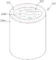
图7显示根据本发明的第四优选实施例的光生物反应设备的立体示意图。Fig. 7 shows a schematic perspective view of a photobioreaction device according to a fourth preferred embodiment of the present invention.
如图7所示,图示的光生物反应设备主要包括一个圆筒形容器200,其具有外壁200a和内壁200b。As shown in FIG. 7 , the illustrated photobioreaction device mainly includes a
在图7所示的实施例中,在外壁200a和内壁200b之间限定第一空间201,该第一空间201作为在其中容纳光生物培养液(例如,含有微藻的培养液)的光生物反应器。由内壁200b环绕所形成的第二空间202作为在其中容纳热容量较大的吸热介质(例如,水)的保温容器。In the embodiment shown in FIG. 7, a
在图7所示的实施例中,光生物反应器和保温容器具有圆柱形壁面,因此,能够增大光生物反应器和保温容器之间的相互接触面积,提高热交换效率。In the embodiment shown in FIG. 7 , the photobioreactor and the heat preservation container have cylindrical walls, therefore, the mutual contact area between the photobioreactor and the heat preservation container can be increased, and the heat exchange efficiency can be improved.
如图7所示,容纳在第二空间202中的吸热介质与容纳在第一空间201中的光生物培养液之间能够通过内壁200b进行热交换,从而提高光生物反应器中的光生物培养液的热容量,保证其温度稳定。As shown in Figure 7, heat exchange can be performed between the heat-absorbing medium contained in the
请继续参见图7,外壁200a和内壁200b之间的距离在1cm至25cm的范围内,这样就能够将光穿过光生物培养液的光程控制在较短的范围内,从而能够提高养殖效率。Please continue to refer to Figure 7, the distance between the
在本发明的另一个优选实施例中,外壁200a和内壁200b之间的距离在2cm至10cm的范围内。更优选地,外壁200a和内壁200b之间的距离在3cm至8cm的范围内。In another preferred embodiment of the present invention, the distance between the
与现有技术相比,本发明的上述各个实施例的光生物反应设备至少具有如下优点:Compared with the prior art, the photobioreaction equipment of the above-mentioned embodiments of the present invention has at least the following advantages:
1)热容量大,利用昼夜环境温度变化(利用完全的自然能),实现稳定的养殖温度。1) The heat capacity is large, and the stable breeding temperature can be realized by utilizing the temperature change of the day and night environment (using complete natural energy).
2)中间冷却水不需泵循环,可节省能耗。2) The intermediate cooling water does not need pump circulation, which can save energy consumption.
3)养殖光程短,节约养殖用水,实现高浓度养殖。3) The optical path of breeding is short, saving water for breeding and realizing high-concentration breeding.
4)在养殖液内进行搅拌,搅拌水量减少,通气能耗降低。4) Stirring is carried out in the culture liquid, the amount of stirring water is reduced, and the energy consumption of ventilation is reduced.
5)曝气分布均一,可改善贴壁状况。5) The aeration distribution is uniform, which can improve the adhesion condition.
下面通过以拟微绿球藻养殖试验组来说明本发明光生物培养设备对养殖效果和效率的影响。首先对各个试验组的光生物反应设备的情况进行简单说明,。The impact of the photobiological cultivation equipment of the present invention on the cultivation effect and efficiency will be illustrated below by using the Nannochloropsis pseudochloropsis cultivation test group. Firstly, briefly explain the conditions of the photobiological reaction equipment of each test group.
图8(a)显示第一试验组的光生物反应设备:其为由塑料袋制成的普通的板式反应器,光程LP=10cm,容积为50L,微藻浓度为0.15vvm,曝气流量为7.5L/min。Figure 8(a) shows the photobiological reaction equipment of the first test group: it is a common plate reactor made of plastic bags, the light path LP=10cm, the volume is 50L, the microalgae concentration is 0.15vvm, and the aeration flow rate It is 7.5L/min.
图8(b)显示第二试验组的光生物反应设备:其为由塑料袋制成的普通的板式反应器,光程LP=20cm,容积为100L,微藻浓度为0.15vvm,流量为15L/min。Figure 8(b) shows the photobiological reaction equipment of the second test group: it is a common plate reactor made of plastic bags, the light path LP=20cm, the volume is 100L, the microalgae concentration is 0.15vvm, and the flow rate is 15L /min.
图8(c)显示第三试验组为本发明的光生物反应设备:其为中间放置玻璃水槽的塑料袋制的板式反应器,光程LP=5cm,容积为50L,微藻浓度为0.15vvm,流量为7.5L/min。Fig. 8 (c) shows that the 3rd test group is the photobiological reaction equipment of the present invention: it is the plate reactor made of the plastic bag of placing glass tank in the middle, light path LP=5cm, volume is 50L, and microalgae concentration is 0.15vvm , the flow rate is 7.5L/min.
图9显示以上三个试验组从2011年8月1日至2011年8月11日的养殖速度比较图。Figure 9 shows the comparison of the breeding speeds of the above three test groups from August 1, 2011 to August 11, 2011.
如图9所示,除了开始几天外,总体而言,第三试验组的光生物反应设备的OD变化最快,养殖速度最快、第一试验组的光生物反应设备的养殖速度其次、第二试验组的光生物反应设备的养殖速度最慢。而且,从图9中可以清楚地看出,相对于第一和第二试验组的光生物反应设备,越到后期,第三试验组的光生物反应设备的养殖速度就变得越快。As shown in Figure 9, in addition to the first few days, generally speaking, the OD of the photobioreaction equipment of the third test group changed the fastest, and the cultivation speed was the fastest, and the cultivation speed of the photobioreaction equipment of the first test group was second, The breeding speed of the photobioreactor equipment in the second test group was the slowest. Moreover, it can be clearly seen from FIG. 9 that, compared with the photobioreactor devices of the first and second test groups, the breeding speed of the photobioreactor devices of the third test group becomes faster in the later stage.
由此可见,光程较短的第三试验组的光生物反应设备高于其他2个比较实验结果。这就初步验证了当初的本实验的设想。即回避了短光程反应器的温升快及宽光程反应器的能耗大的问题,实现了能控制温度在低于38℃,低通气能耗,并且高密度养殖。It can be seen that the photobiological reaction equipment of the third experimental group with a shorter optical path is higher than the results of the other two comparative experiments. This preliminarily verified the original idea of this experiment. That is to say, it avoids the problems of fast temperature rise of short light path reactors and high energy consumption of wide light path reactors, realizes temperature control below 38°C, low ventilation energy consumption, and high-density breeding.
图10显示以上三个试验组从2011年8月1日至2011年8月11日的日平均养殖速度比较图。Figure 10 shows the comparison chart of the average daily breeding speed of the above three test groups from August 1, 2011 to August 11, 2011.
如图10所示,第一和第二试验组的光生物反应设备的日平均养殖速度相当,其中第一试验组为0.16,第二试验组为0.17。但是,第三试验组的日平均养殖速度高达0.27,大约是前面2个的一倍,与10cm反应器相比,新型反应器温度得到有效控制,OD增长速度得到大幅度提高。As shown in Figure 10, the average daily breeding speed of the photobioreaction equipment of the first and second test groups is equivalent, wherein the first test group is 0.16, and the second test group is 0.17. However, the average daily breeding speed of the third test group was as high as 0.27, about twice that of the previous two. Compared with the 10cm reactor, the temperature of the new reactor was effectively controlled, and the OD growth rate was greatly improved.
图11显示以上三个试验组的单位反应器产量比较。Figure 11 shows the comparison of unit reactor yields of the above three test groups.
如图11所示,如果以第一试验组的光生物反应设备的产量为100%,那么第二试验组的光生物反应设备的产量相对于第一组为211%,第三试验组的光生物反应设备相对于第一组为168%。As shown in Figure 11, if the output of the photobioreaction equipment of the first test group is 100%, then the output of the photobioreactor equipment of the second test group is 211% relative to the first group, and the photobioreactor equipment of the third test group is 211%. Bioreactor equipment is 168% relative to the first group.
由此,可见,第一组的10cm光程光生物反应设备因在前述环境条件下,养殖温度偏高,阻碍细胞生长。而其他得到良好温控的反应器有利于细胞生长。而同样光程的第三组光生物反应设备在同样通气能耗的条件下,单台光生物反应设备产量约为第一试验组的10cm反应器的1.7倍。而对于通气能耗2倍的20cm宽光程的第二组反应器,单台反应器总产量仅约为第一试验组的10cm反应器的2.1倍。其生产效率低于第三组光生物反应设备。Thus, it can be seen that the 10cm optical path photobioreaction equipment of the first group hinders cell growth due to the relatively high culture temperature under the aforementioned environmental conditions. Other well-controlled reactors favor cell growth. While the third group of photobioreactors with the same optical path has the same energy consumption of ventilation, the output of a single photobioreactor is about 1.7 times that of the 10cm reactor of the first test group. However, for the second group of reactors with a 20 cm wide optical path whose aeration energy consumption is 2 times, the total output of a single reactor is only about 2.1 times that of the 10 cm reactors of the first test group. Its production efficiency is lower than that of the third group of photobiological reaction equipment.
图12显示以上三个试验组的光生物反应设备在养殖期间单位占地面积日产量变化。如图12所示,第三试验组的光生物反应设备在养殖期间单位占地面积日产量远高于具有同样容积的第一试验组的光生物反应设备,仅稍低于具有2倍容积的第二试验组的光生物反应设备。Figure 12 shows the changes in the daily output per unit area of the photobioreaction equipment of the above three test groups during the breeding period. As shown in Figure 12, the photobioreactor equipment of the third test group had a much higher daily output per unit floor area during cultivation than the photobioreactor equipment of the first test group with the same volume, and was only slightly lower than that of the one with 2 times the volume. Photobioreactor equipment for the second test group.
图13显示环境温度(气温)及以上三个试验组的各个反应器的一天中最高温度(PM4:00-5:00)的数据比较。如图13所示,5cm光程的新反应器较10cm光程的反应器温度得到有效控制。Figure 13 shows the data comparison of the ambient temperature (air temperature) and the maximum temperature (PM4:00-5:00) of each reactor in the above three test groups in a day. As shown in Figure 13, the temperature of the new reactor with 5 cm path length is more effectively controlled than that of the reactor with 10 cm path length.
虽然结合附图对本发明进行了说明,但是附图中公开的实施例旨在对本发明优选实施方式进行示例性说明,而不能理解为对本发明的一种限制。Although the present invention has been described with reference to the accompanying drawings, the embodiments disclosed in the accompanying drawings are intended to illustrate preferred embodiments of the present invention and should not be construed as a limitation of the present invention.
虽然本总体发明构思的一些实施例已被显示和说明,本领域普通技术人员将理解,在不背离本总体发明构思的原则和精神的情况下,可对这些实施例做出改变,本发明的范围以权利要求和它们的等同物限定。While certain embodiments of the present general inventive concept have been shown and described, it will be understood by those of ordinary skill in the art that changes may be made to these embodiments without departing from the principles and spirit of the present general inventive concept. The scope is defined by the claims and their equivalents.
Claims (15)
Translated fromChinesePriority Applications (1)
| Application Number | Priority Date | Filing Date | Title |
|---|---|---|---|
| CN201110449620XACN103184142A (en) | 2011-12-29 | 2011-12-29 | Light biological reaction equipment and light biological culture method |
Applications Claiming Priority (1)
| Application Number | Priority Date | Filing Date | Title |
|---|---|---|---|
| CN201110449620XACN103184142A (en) | 2011-12-29 | 2011-12-29 | Light biological reaction equipment and light biological culture method |
Publications (1)
| Publication Number | Publication Date |
|---|---|
| CN103184142Atrue CN103184142A (en) | 2013-07-03 |
Family
ID=48675593
Family Applications (1)
| Application Number | Title | Priority Date | Filing Date |
|---|---|---|---|
| CN201110449620XAPendingCN103184142A (en) | 2011-12-29 | 2011-12-29 | Light biological reaction equipment and light biological culture method |
Country Status (1)
| Country | Link |
|---|---|
| CN (1) | CN103184142A (en) |
Cited By (1)
| Publication number | Priority date | Publication date | Assignee | Title |
|---|---|---|---|---|
| CN104560634A (en)* | 2014-12-23 | 2015-04-29 | 新奥科技发展有限公司 | Immobilized microalgae breeding method and device thereof |
Citations (4)
| Publication number | Priority date | Publication date | Assignee | Title |
|---|---|---|---|---|
| FR2564854B1 (en)* | 1984-05-28 | 1986-11-14 | Commissariat Energie Atomique | PHOTOBIOREACTOR. |
| CN1697875A (en)* | 2003-12-16 | 2005-11-16 | 仁菏大学校产学协力团 | Multilayer photobioreactor and method for cultivating photosynthetic microorganisms therewith |
| US20090291490A1 (en)* | 2008-01-18 | 2009-11-26 | Touchstone Research Laboratory, Ltd. | Photo-Bioreactor |
| WO2011017171A1 (en)* | 2009-07-28 | 2011-02-10 | Joule Unlimited, Inc. | Photobioreactors, solar energy gathering systems, and thermal control methods |
- 2011
- 2011-12-29CNCN201110449620XApatent/CN103184142A/enactivePending
Patent Citations (5)
| Publication number | Priority date | Publication date | Assignee | Title |
|---|---|---|---|---|
| FR2564854B1 (en)* | 1984-05-28 | 1986-11-14 | Commissariat Energie Atomique | PHOTOBIOREACTOR. |
| CN1697875A (en)* | 2003-12-16 | 2005-11-16 | 仁菏大学校产学协力团 | Multilayer photobioreactor and method for cultivating photosynthetic microorganisms therewith |
| US20090291490A1 (en)* | 2008-01-18 | 2009-11-26 | Touchstone Research Laboratory, Ltd. | Photo-Bioreactor |
| WO2011017171A1 (en)* | 2009-07-28 | 2011-02-10 | Joule Unlimited, Inc. | Photobioreactors, solar energy gathering systems, and thermal control methods |
| US20110217692A1 (en)* | 2009-07-28 | 2011-09-08 | Morgan Frederick M | Photobioreactors, Solar Energy Gathering Systems, And Thermal Control Methods |
Cited By (2)
| Publication number | Priority date | Publication date | Assignee | Title |
|---|---|---|---|---|
| CN104560634A (en)* | 2014-12-23 | 2015-04-29 | 新奥科技发展有限公司 | Immobilized microalgae breeding method and device thereof |
| CN104560634B (en)* | 2014-12-23 | 2017-01-11 | 新奥科技发展有限公司 | Immobilized microalgae breeding method and device thereof |
Similar Documents
| Publication | Publication Date | Title |
|---|---|---|
| Xu et al. | Microalgal bioreactors: challenges and opportunities | |
| CN102296022B (en) | Bioreactor | |
| US20100304456A1 (en) | Continuous-batch hybrid process for production of oil and other useful products from photosynthetic microbes | |
| WO2005006838A2 (en) | Flat panel photobioreactor | |
| WO2010115996A1 (en) | Photobioreactor in a closed medium for cultivating photosynthetic micro-organisms | |
| CN101709264B (en) | Optical bioreactor | |
| CN101405385A (en) | Photobioreactor and uses therefor | |
| CN105368699B (en) | Make the microalgae photobiological reactor of light decentralized medium using nanometer light guide plate | |
| CN104726321B (en) | A kind of racetrack bioreactor suitable for sunlight batch production | |
| CN102382754A (en) | Optical fiber photobioreactor for making full use of 'flash effect' of microalgae | |
| CN108060058A (en) | A photobioreactor for high-density cultivation of microalgae | |
| CN1721523A (en) | Pipeline Photobioreactor for Scale Cultivation of Microalgae | |
| CN105219635A (en) | A kind of built-in light source air lift type inner ring stream photosynthesis physiological target | |
| CN201424476Y (en) | A photobioreactor | |
| CN204999909U (en) | Circulation photobioreactor in built in light source gas lift formula | |
| CN102443536B (en) | Auxiliary device for photobioreactor | |
| CN102787066A (en) | Enclosed perfusion-type photobioreactor | |
| CN201381319Y (en) | Optical bioreactor for nursing microalgae | |
| CN103184142A (en) | Light biological reaction equipment and light biological culture method | |
| CN106916723B (en) | A kind of haematococcus pluvialis cultural method and culture apparatus | |
| EP3013938A2 (en) | Floating photobioreactor system comprising a floating photobioreactor and an integrated paddle wheel and an airlift and methods of use | |
| CN104232471A (en) | Culturing method of photosynthetic organism | |
| CN108285859B (en) | Novel pneumatic nostoc algae runway pond culture system | |
| CN204644342U (en) | For cultivating the microporous culture plate of photosynthetic microorganism | |
| CN105462816B (en) | Realize that sunlight divides uniformly distributed raceway pond microalgae reactor using nanometer light guide plate |
Legal Events
| Date | Code | Title | Description |
|---|---|---|---|
| C06 | Publication | ||
| PB01 | Publication | ||
| C10 | Entry into substantive examination | ||
| SE01 | Entry into force of request for substantive examination | ||
| RJ01 | Rejection of invention patent application after publication | ||
| RJ01 | Rejection of invention patent application after publication | Application publication date:20130703 |