CN103169520A - Surgical cutting suture instrument provided with stroke indication device - Google Patents
Surgical cutting suture instrument provided with stroke indication deviceDownload PDFInfo
- Publication number
- CN103169520A CN103169520ACN2013100890795ACN201310089079ACN103169520ACN 103169520 ACN103169520 ACN 103169520ACN 2013100890795 ACN2013100890795 ACN 2013100890795ACN 201310089079 ACN201310089079 ACN 201310089079ACN 103169520 ACN103169520 ACN 103169520A
- Authority
- CN
- China
- Prior art keywords
- mentioned
- block
- indicator
- limit
- wheel
- Prior art date
- Legal status (The legal status is an assumption and is not a legal conclusion. Google has not performed a legal analysis and makes no representation as to the accuracy of the status listed.)
- Granted
Links
- 230000005540biological transmissionEffects0.000claimsabstractdescription69
- 244000309464bullSpecies0.000claimsdescription7
- 238000003780insertionMethods0.000claimsdescription4
- 230000037431insertionEffects0.000claimsdescription4
- 238000010586diagramMethods0.000description23
- 238000009434installationMethods0.000description11
- 238000010304firingMethods0.000description8
- 238000000034methodMethods0.000description7
- 230000009471actionEffects0.000description6
- 230000008569processEffects0.000description5
- 230000007812deficiencyEffects0.000description2
- 230000002708enhancing effectEffects0.000description2
- 210000001035gastrointestinal tractAnatomy0.000description2
- 210000002345respiratory systemAnatomy0.000description2
- 208000002847Surgical WoundDiseases0.000description1
- 206010052428WoundDiseases0.000description1
- 208000027418Wounds and injuryDiseases0.000description1
- 230000003872anastomosisEffects0.000description1
- 210000004204blood vesselAnatomy0.000description1
- 230000008859changeEffects0.000description1
- 210000001072colonAnatomy0.000description1
- 239000003086colorantSubstances0.000description1
- 230000007547defectEffects0.000description1
- 238000006073displacement reactionMethods0.000description1
- 210000001198duodenumAnatomy0.000description1
- 230000000694effectsEffects0.000description1
- 210000003238esophagusAnatomy0.000description1
- 230000002496gastric effectEffects0.000description1
- 238000010879hemorrhoidectomyMethods0.000description1
- 210000004072lungAnatomy0.000description1
- 210000000056organAnatomy0.000description1
- 210000000664rectumAnatomy0.000description1
- 210000000813small intestineAnatomy0.000description1
- 210000002784stomachAnatomy0.000description1
- 230000008093supporting effectEffects0.000description1
- 210000003437tracheaAnatomy0.000description1
- 230000002792vascularEffects0.000description1
Images


Landscapes
- Surgical Instruments (AREA)
Abstract
Translated fromChinese
Description
Translated fromChinese技术领域technical field
本发明涉及医疗器械领域,特别涉及一种具有行程指示装置的外科切割缝合器械。 The invention relates to the field of medical instruments, in particular to a surgical cutting and suturing instrument with a stroke indicating device. the
背景技术Background technique
在医学科学的外科手术中,自从20世纪60年代的第一把缝钉类产品以来,医用缝合器已成为辅助于刀口缝合过程中的必不可少的一种医疗器械。各种外科用医用缝合器正在外科手术中被广泛地用于缝合人体消化道组织、呼吸道组织和血管组织,可以减少手术时间,提高手术质量。它们通常被用于消化道中食管、胃、十二指肠、小肠、结肠和直肠等端端、端侧及侧侧缝合手术或痔切除和胃幽门造口等形成通道或闭合切口的手术,也被用于呼吸道中肺和气管等缝合手术和血管组织的缝合手术,特别适用于显露和操作困难的器官和组织的缝合手术。 In the surgical operation of medical science, since the first staple product in the 1960s, the medical stapler has become an indispensable medical device in the process of suturing the knife edge. Various surgical medical staplers are widely used in surgical operations to suture human digestive tract tissues, respiratory tract tissues and vascular tissues, which can reduce operation time and improve operation quality. They are usually used for end-to-end, end-to-side, and side-to-side suture operations such as esophagus, stomach, duodenum, small intestine, colon, and rectum in the digestive tract, or operations for forming channels or closing incisions such as hemorrhoidectomy and gastric pylorostomy. It is used in the suture operation of the lung and trachea in the respiratory tract and the suture operation of blood vessel tissue, especially suitable for the suture operation of organs and tissues that are difficult to expose and operate. the
外科切割缝合器械中,直线切割缝合器具有缝合与切割两个功能,在进行伤口缝合的同时,将多余的组织切除,直线切割缝合器已被广泛用于外科手术的伤口缝合、内部组织缝合与切割中。现有的直线切割缝合器一般包括上、下两个钳夹,以及用于闭合上、下钳夹的闭合把手,相对设置在上、下钳夹前端的钉仓和抵钉座,设于钉仓内并可同时相对于钉仓移动的击发片和切刀,以及用于驱动击发片和切刀移动的推扭。钉仓内排列设有缝合钉,击发片依次推动推钉片并将缝合钉推向抵钉座,所述的切刀将位于钉仓和抵钉座之间的组织切断,在这些过程中,通过行程指示装置能 更好的了解器械的工作状态,在现有技术中,以直线切割缝合器为例,申请公布号为CN102813539A的专利申请公布了一种带有行程指示装置的直线切割缝合器,该申请公布的技术方案虽然解决了常见的直线切割缝合器不能明确显示切刀和击发片的行程而对手术操作带来不便的缺陷,但该技术方案仍存在不足,由于行程指示装置的部分滑槽设置在手柄外壳内,当用力按压手柄外壳时,可能会导致滑槽有一定程度的变形而导致其他零件难以配合,此外,限制传动齿轮单向旋转的零件比较复杂而导致对零件的配合度的要求较高。基于现有技术中的上述不足,有待提出新的行程指示的技术方案。 Among the surgical cutting and suturing instruments, the linear cutting and suturing device has two functions of suturing and cutting. While suturing the wound, it removes excess tissue. The linear cutting and suturing device has been widely used in surgical wound suturing, internal tissue suturing and Cutting. Existing linear cutting staplers generally include upper and lower jaws, and closing handles for closing the upper and lower jaws. The firing piece and the cutting knife in the magazine can move relative to the staple cartridge at the same time, and the push torque for driving the firing piece and the cutting knife to move. Staples are arranged in the staple cartridge, and the firing piece pushes the staple pusher in turn and pushes the staples to the staple abutment seat, and the cutter cuts off the tissue between the staple cartridge and the staple abutment seat. During these processes, The working state of the instrument can be better understood through the stroke indicating device. In the prior art, taking the linear cutting stapler as an example, the patent application whose application publication number is CN102813539A discloses a linear cutting stapler with a stroke indicating device , although the technical solution disclosed in this application solves the defect that the common linear cutting stapler cannot clearly display the stroke of the cutting knife and the firing piece, which brings inconvenience to the surgical operation, the technical solution still has deficiencies, because the part of the stroke indicating device The chute is set in the handle shell. When the handle shell is pressed hard, the chute may be deformed to a certain extent, making it difficult to cooperate with other parts. In addition, the parts that limit the one-way rotation of the transmission gear are more complicated, which leads to the matching of the parts. Degree requirements are higher. Based on the above-mentioned deficiencies in the prior art, a new technical solution for the itinerary indication is yet to be proposed. the
发明内容Contents of the invention
本发明提供了一种具有行程指示装置的外科切割缝合器械,以至少解决现有技术中由于行程指示装置的部分滑槽设置在手柄外壳内,当用力按压手柄外壳时,可能会导致滑槽有一定程度的变形而导致其他零件难以配合,以及由于限制传动齿轮单向旋转的零件比较复杂而导致对零件的配合度的要求较高的技术问题。 The present invention provides a surgical cutting and suturing instrument with a stroke indicating device to at least solve the problem that in the prior art, since part of the chute of the stroke indicating device is arranged in the handle shell, when the handle shell is pressed hard, the chute may be damaged. A certain degree of deformation makes it difficult to cooperate with other parts, and due to the complexity of the parts that limit the one-way rotation of the transmission gear, it leads to technical problems that require a high degree of cooperation for the parts. the
本发明提供了一种具有行程指示装置的外科切割缝合器械,包括传动组件、指示组件和限位组件,上述传动组件包括闭合夹板、导条、行程块及传动轮,上述导条插入上述行程块,并与上述行程块通过弹簧连接,上述导条与上述闭合夹板滑动连接,上述行程块与上述传动轮啮合连接;上述指示组件包括指示座、指示轮、指示盘及组件固定块,上述指示轮穿过上述组件固定块与上述指示盘固定安装,上述指示轮转动连接在上述指示座上,上述组件固定块固定安装在上述指示座上;上述限位组件包括限位绳、指示限位块、限位滑块及推环,上述指示限位块转动连接在上述限位滑块上,上述限位绳的两端分别连接在上述限位滑块及上述推环上;上述传动组件驱动上述指示组件显示指示信息,上述限位组件与传动组件配合防止上述指示轮沿顺时针方向旋转。 The present invention provides a surgical cutting and suturing instrument with a stroke indicating device, which includes a transmission assembly, an indication assembly and a limit assembly. The above transmission assembly includes a closing splint, a guide bar, a stroke block and a drive wheel. The above guide bar is inserted into the above stroke block , and connected with the above-mentioned stroke block through a spring, the above-mentioned guide bar is slidingly connected with the above-mentioned closed splint, and the above-mentioned stroke block is meshed with the above-mentioned transmission wheel; The above-mentioned component fixing block is fixedly installed with the above-mentioned indicating plate, the above-mentioned indicating wheel is rotatably connected to the above-mentioned indicating seat, and the above-mentioned component fixing block is fixedly installed on the above-mentioned indicating seat; the above-mentioned limiting component includes a limit rope, an indicating limit block, A limit slider and a push ring, the above-mentioned indicator limit block is rotatably connected to the above-mentioned limit slider, and the two ends of the above-mentioned limit rope are respectively connected to the above-mentioned limit slider and the above-mentioned push ring; the above-mentioned transmission assembly drives the above-mentioned indicator The component displays indication information, and the above-mentioned limit component cooperates with the transmission component to prevent the above-mentioned indicator wheel from rotating clockwise. the
优选地,上述传动组件驱动上述指示组件显示指示信息是指上述行程块带动上述传动轮驱动上述指示轮及上述指示盘旋转使上述指示盘显示指示信息;上述限位组件与传动组件配合防止上述指示轮沿顺时针方向旋转是指上述指示限位块啮合于上述传动轮防止上述传动轮驱动上述指示轮沿顺时针方向旋转。 Preferably, the above transmission assembly drives the above indication assembly to display indication information means that the above stroke block drives the above transmission wheel to drive the above indication wheel and the above indication disk to rotate so that the above indication disk displays indication information; the above limit assembly cooperates with the transmission assembly to prevent the above indication The clockwise rotation of the wheel means that the above-mentioned indicating limit block is engaged with the above-mentioned driving wheel to prevent the above-mentioned driving wheel from driving the above-mentioned indicating wheel to rotate in the clockwise direction. the
优选地,上述传动轮设有小齿轮、棘齿齿轮以及大齿轮,上述棘齿齿轮设置于上述小齿轮和上述大齿轮之间,上述小齿轮、上述棘齿齿轮以及上述大齿轮连为一体,上述行程块带动上述大齿轮转动从而使上述小齿轮驱动上述指示轮及上述指示盘旋转,上述指示限位块啮合于上述传动轮上的上述棘齿齿轮防止上述传动轮上的上述小齿轮驱动上述指示轮沿顺时针方向旋转。 Preferably, the transmission wheel is provided with a pinion, a ratchet gear and a bull gear, the ratchet gear is arranged between the pinion gear and the bull gear, the pinion gear, the ratchet gear and the bull gear are connected as one, The above-mentioned travel block drives the above-mentioned large gear to rotate so that the above-mentioned pinion gear drives the above-mentioned indicating wheel and the above-mentioned indicating plate to rotate, and the above-mentioned indicating limit block meshes with the above-mentioned ratchet gear on the above-mentioned transmission wheel to prevent the above-mentioned small gear on the above-mentioned transmission wheel from driving the above-mentioned The indicator wheel rotates clockwise. the
优选地,上述闭合夹板上固定连接行程块复位弹性部件,上述指示座设有下弹弹性部件。 Preferably, the above-mentioned closing splint is fixedly connected with a return elastic part of the stroke block, and the above-mentioned indicating seat is provided with a spring-down elastic part. the
优选地,上述行程块复位弹性部件为行程块复位簧,上述下弹弹性部件为下弹板簧,上述闭合夹板上固定连接行程块复位弹性部件为上述闭合夹板上焊接行程块复位簧。 Preferably, the stroke block reset elastic component is a stroke block reset spring, the lower elastic component is a lower spring leaf spring, and the stroke block reset elastic component fixedly connected to the closing splint is a stroke block reset spring welded on the closing splint. the
优选地,上述外科切割缝合器械满足以下一项或几项: Preferably, the above-mentioned surgical cutting and suturing instrument satisfies one or more of the following:
a.上述导条设有插片,上述插片插入上述行程块,上述导条和上述行程块通过第一拉簧连接; a. The above-mentioned guide bar is provided with an insert, and the above-mentioned insert is inserted into the above-mentioned stroke block, and the above-mentioned guide bar and the above-mentioned stroke block are connected by the first tension spring;
b.上述导条设有滑动销,上述闭合夹板设有导向槽,上述滑动销可在上述导向槽内滑动; b. The above-mentioned guide bar is provided with a sliding pin, and the above-mentioned closed splint is provided with a guide groove, and the above-mentioned sliding pin can slide in the above-mentioned guide groove;
c.上述指示座和上述指示轮通过第一扭簧连接; c. The above-mentioned indicator seat and the above-mentioned indicator wheel are connected by the first torsion spring;
d.上述指示限位块设有限位台; d. The above-mentioned indicating limit block is provided with a limit platform;
e.上述限位滑块设有阶梯销轴,上述指示限位块转动安装于上述阶梯销轴上; e. The above-mentioned limit slider is provided with a stepped pin shaft, and the above-mentioned indicating limit block is rotatably installed on the above-mentioned stepped pin shaft;
f.上述指示限位块和上述限位滑块通过第二扭簧连接。 f. The above-mentioned indicating limit block and the above-mentioned limit slider are connected by a second torsion spring. the
优选地,上述外科切割缝合器械还包括固定夹板,上述固定夹板与上述闭合夹板配合的转动销,上述限位绳的一端连接于上述推环,上述限位绳的另一端绕过上述转动销连接于上述限位滑块。 Preferably, the above-mentioned surgical cutting and suturing instrument also includes a fixed splint, a rotating pin that cooperates between the above-mentioned fixed splint and the above-mentioned closing splint, one end of the above-mentioned limit rope is connected to the above-mentioned push ring, and the other end of the above-mentioned limit rope is connected around the above-mentioned rotating pin on the above limit slider. the
优选地,上述推环套在上述固定夹板上,上述指示座固定安装在上述闭合夹板上,上述限位滑块与上述指示座滑动连接,上述行程块滑动连接于上述指示座,上述传动轮的一端转动连接在上述指示座上,上述传动轮的另一端转动连接在上述组件固定块上。 Preferably, the above-mentioned push ring is sleeved on the above-mentioned fixed splint, the above-mentioned indicating seat is fixedly installed on the above-mentioned closed splint, the above-mentioned limit slider is slidably connected to the above-mentioned indicating seat, the above-mentioned stroke block is slidably connected to the above-mentioned indicating seat, and the above-mentioned transmission wheel One end is rotatably connected to the above-mentioned indicating seat, and the other end of the above-mentioned transmission wheel is rotatably connected to the above-mentioned component fixing block. the
优选地,上述外科切割缝合器械满足以下一项或几项: Preferably, the above-mentioned surgical cutting and suturing instrument satisfies one or more of the following:
I.上述指示座上设有限位滑块滑槽,上述限位滑块上设有限位滑块轨道,上述限位滑块轨道在上述限位滑块滑槽中滑动; I. The above-mentioned indicator seat is provided with a limit slider chute, and the above-mentioned limit slider is provided with a limit slider track, and the above-mentioned limit slider track slides in the above-mentioned limit slider chute;
II.上述行程块上设有滑动轴,上述指示座上设有行程块导轨,上述滑动轴在上述行程块导轨内滑动; II. The above-mentioned stroke block is provided with a sliding shaft, and the above-mentioned indicating seat is provided with a stroke block guide rail, and the above-mentioned sliding shaft slides in the above-mentioned stroke block guide rail;
III.上述组件固定块的中部设有传动轮销槽,上述传动轮设有传动轮销,上述传动轮销的上端插入上述传动轮销槽。 III. The middle part of the fixing block of the above-mentioned assembly is provided with a transmission wheel pin groove, and the above-mentioned transmission wheel is provided with a transmission wheel pin, and the upper end of the above-mentioned transmission wheel pin is inserted into the above-mentioned transmission wheel pin groove. the
优选地,上述外科切割缝合器械为直线切割缝合器。 Preferably, the above-mentioned surgical cutting and suturing instrument is a linear cutting and suturing instrument. the
在本发明中,行程指示装置的零件不再与手柄外壳内的滑槽配合,当用力按压手柄外壳时,行程指示装置的零件不再因为手柄外壳内的滑槽可能有一定程度的变形而难以配合,增强了行程指示的稳定性。此外,本发明简化了限制传动轮单向旋转的零件,进一步增强了行程指示的稳定性。达到了增强行程指示的稳定性的技术效果。指示盘的显示窗口置于器械上表面,不再置于器械的两侧,视窗视野更开阔,使操作者更容易观察到行程指示的信息,本发明外科切割缝合器械的行程指示装置更方便手术操作。 In the present invention, the parts of the stroke indicating device are no longer matched with the chute in the handle shell, and when the handle shell is pressed hard, the parts of the stroke indicating device are no longer difficult because the chute in the handle shell may have a certain degree of deformation. Cooperate to enhance the stability of the stroke indication. In addition, the invention simplifies the parts that limit the one-way rotation of the transmission wheel, further enhancing the stability of the stroke indication. The technical effect of enhancing the stability of the stroke indication is achieved. The display window of the indicator plate is placed on the upper surface of the instrument instead of on both sides of the instrument. The view of the window is wider, making it easier for the operator to observe the information of the stroke indication. The stroke indicator device of the surgical cutting and suturing instrument of the present invention is more convenient for operation. operate. the
附图说明Description of drawings
上述仅是本发明技术方案的概述,为了能够更清楚了解本发明的技术手段,以下结合附图与具体实施方式对本发明作进一步的详细说明,本发明包括但不限于以下附图及实施例。 The above is only an overview of the technical solution of the present invention. In order to better understand the technical means of the present invention, the present invention will be further described in detail below in conjunction with the drawings and specific embodiments. The present invention includes but is not limited to the following drawings and embodiments. the
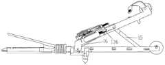
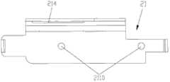
图1是本发明提供的一种优选实施例的直线切割缝合器的示意图。 Fig. 1 is a schematic diagram of a linear cutting stapler according to a preferred embodiment of the present invention. the
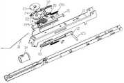
图2是本发明提供的一种优选实施例的直线切割缝合器的爆炸示意图。 Fig. 2 is an exploded schematic view of a linear cutting stapler according to a preferred embodiment of the present invention. the
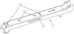
图3是本发明提供的一种优选实施例的直线切割缝合器的闭合夹板示意图。 Fig. 3 is a schematic diagram of a closing splint of a linear cutting stapler according to a preferred embodiment of the present invention. the
图4是本发明提供的一种优选实施例的直线切割缝合器的导条的示意图。 Fig. 4 is a schematic diagram of a guide strip of a linear cutting stapler according to a preferred embodiment of the present invention. the
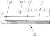
图5-1是本发明提供的一种优选实施例的直线切割缝合器的行程块的排齿朝上的行程块示意图。 Fig. 5-1 is a schematic diagram of the stroke block of the stroke block of the linear cutting stapler according to a preferred embodiment of the present invention, with the rows of teeth facing upward. the
图5-2是本发明提供的一种优选实施例的直线切割缝合器的行程块的排齿朝下的行程块示意图。 Fig. 5-2 is a schematic diagram of the stroke block with the row of teeth facing downward of the stroke block of the linear cutting stapler according to a preferred embodiment of the present invention. the
图5-3是本发明提供的一种优选实施例的直线切割缝合器的行程块的立体示意图。 Fig. 5-3 is a schematic perspective view of a stroke block of a linear cutting stapler according to a preferred embodiment of the present invention. the
图6是本发明提供的一种优选实施例的直线切割缝合器的行程块和导条配合安装的示意图。 Fig. 6 is a schematic diagram of the cooperating installation of the stroke block and the guide bar of a linear cutting stapler according to a preferred embodiment of the present invention. the
图7是本发明提供的一种优选实施例的直线切割缝合器的传动轮和传动轮销的示意图。 Fig. 7 is a schematic diagram of a transmission wheel and a transmission wheel pin of a linear cutting stapler according to a preferred embodiment of the present invention. the
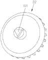
图8-1是本发明提供的一种优选实施例的直线切割缝合器的指示轮的复位扭簧挂钩朝外的指示轮示意图。 Fig. 8-1 is a schematic diagram of the indicator wheel of the linear cutting stapler according to a preferred embodiment of the present invention, with the reset torsion spring hook facing outward. the
图8-2是本发明提供的一种优选实施例的直线切割缝合器的指示轮的多边形凸台朝外的指示轮示意图。 Fig. 8-2 is a schematic diagram of the indicator wheel of the linear cutting stapler according to a preferred embodiment of the present invention, with the polygonal boss facing outward. the
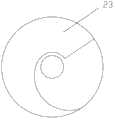
图9-1是本发明提供的一种优选实施例的直线切割缝合器的指示盘示意图。 Fig. 9-1 is a schematic diagram of an indicator plate of a linear cutting stapler according to a preferred embodiment of the present invention. the
图9-2是本发明提供的一种优选实施例的直线切割缝合器的指示盘和指示 轮配合安装的示意图。 Fig. 9-2 is a schematic diagram of the cooperating installation of the indicator plate and the indicator wheel of a linear cutting stapler of a preferred embodiment provided by the present invention. the
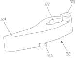
图10是本发明提供的一种优选实施例的直线切割缝合器的指示限位块的示意图。 Fig. 10 is a schematic diagram of an indicating limit block of a linear cutting stapler according to a preferred embodiment of the present invention. the
图11是本发明提供的一种优选实施例的直线切割缝合器的限位滑块的示意图。 Fig. 11 is a schematic diagram of a limit slider of a linear cutting stapler according to a preferred embodiment of the present invention. the
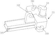
图12是本发明提供的一种优选实施例的直线切割缝合器的指示限位块和限位滑块配合安装的示意图。 Fig. 12 is a schematic diagram of the cooperating installation of the indicating limit block and the limit slider of a linear cutting stapler according to a preferred embodiment of the present invention. the
图13-1是本发明提供的一种优选实施例的直线切割缝合器的组件固定块的仰视示意图。 Fig. 13-1 is a schematic bottom view of a component fixing block of a linear cutting stapler according to a preferred embodiment of the present invention. the
图13-2是本发明提供的一种优选实施例的直线切割缝合器的组件固定块的主视示意图。 Fig. 13-2 is a schematic front view of a component fixing block of a linear cutting stapler according to a preferred embodiment of the present invention. the
图14-1是本发明提供的一种优选实施例的直线切割缝合器的指示座的立体示意图。 Fig. 14-1 is a schematic perspective view of an indicator seat of a linear cutting stapler according to a preferred embodiment of the present invention. the
图14-2是本发明提供的一种优选实施例的直线切割缝合器的指示座的仰视示意图。 Fig. 14-2 is a schematic bottom view of an indicator seat of a linear cutting stapler according to a preferred embodiment of the present invention. the
图14-3是本发明提供的一种优选实施例的直线切割缝合器的指示座的显示导轨下表面的指示座示意图。 Fig. 14-3 is a schematic diagram of the indicator seat showing the lower surface of the guide rail of the indicator seat of the linear cutting stapler according to a preferred embodiment of the present invention. the
图15是本发明提供的一种优选实施例的直线切割缝合器的指示座、指示盘、指示轮和组件固定块配合安装的示意图。 Fig. 15 is a schematic diagram of the cooperating installation of the indicator seat, the indicator plate, the indicator wheel and the assembly fixing block of a linear cutting stapler according to a preferred embodiment of the present invention. the
图16是本发明提供的一种优选实施例的直线切割缝合器的限位绳示意图。 Fig. 16 is a schematic diagram of a limit rope of a linear cutting stapler according to a preferred embodiment of the present invention. the
图17是本发明提供的一种优选实施例的直线切割缝合器的推环的示意图。 Fig. 17 is a schematic diagram of a push ring of a linear cutting stapler according to a preferred embodiment of the present invention. the
图18是本发明提供的一种优选实施例的直线切割缝合器的显示限位绳的直线切割缝合器示意图。 Fig. 18 is a schematic diagram of a linear cutting stapler showing a limiting rope according to a preferred embodiment of the present invention. the
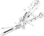
图19是本发明提供的一种优选实施例的直线切割缝合器的初始状态的主视 示意图。 Figure 19 is a schematic front view of the initial state of a linear cutting stapler according to a preferred embodiment of the present invention. the
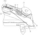
图20是本发明提供的一种优选实施例的直线切割缝合器的初始状态的立体示意图。 Fig. 20 is a schematic perspective view of the initial state of a linear cutting stapler according to a preferred embodiment of the present invention. the
图21是图20的局部示意图。 FIG. 21 is a partial schematic diagram of FIG. 20 . the
图22-1是本发明提供的一种优选实施例的直线切割缝合器的闭合状态的主视示意图。 Fig. 22-1 is a schematic front view of a closed state of a linear cutting stapler according to a preferred embodiment of the present invention. the
图22-2是本发明提供的一种优选实施例的直线切割缝合器的闭合状态的部分零件配合关系的示意图。 Fig. 22-2 is a schematic diagram of the cooperation relationship of some parts in the closed state of the linear cutting stapler according to a preferred embodiment of the present invention. the
图23是本发明提供的一种优选实施例的直线切割缝合器初始状态显示推刀连杆的立体示意图。 Fig. 23 is a three-dimensional schematic diagram showing the push knife link in the initial state of a linear cutting stapler according to a preferred embodiment of the present invention. the
图24-1是本发明提供的一种优选实施例的直线切割缝合器的闭合状态的行程块开始回退的主视示意图。 Fig. 24-1 is a schematic front view of a linear cutting stapler in a closed state in which the stroke block starts to retreat according to a preferred embodiment of the present invention. the
图24-2是本发明提供的一种优选实施例的直线切割缝合器的闭合状态的行程块开始回退的部分零件配合关系的示意图。 Fig. 24-2 is a schematic diagram of the matching relationship of some parts when the stroke block starts to retreat in the closed state of the linear cutting stapler according to a preferred embodiment of the present invention. the
具体实施方式Detailed ways
本实施例提供了一种优选的外科切割缝合器械,以直线切割缝合器为例,包括传动组件、指示组件及限位组件,如图1及图2所示,传动组件包括闭合夹板11、导条12、行程块13、传动轮14、支撑连杆15及推刀连杆16,指示组件包括指示座21、指示轮22、指示盘23及组件固定块24,限位组件包括限位绳31、指示限位块32、限位滑块33及推环34。 This embodiment provides a preferred surgical cutting and suturing instrument. Taking a linear cutting and stapling device as an example, it includes a transmission assembly, an indicating assembly and a limit assembly. As shown in Figures 1 and 2, the transmission assembly includes a closing
如图3所示,上述闭合夹板11一侧开设有导向槽111,上述闭合夹板11的上表面设有安装孔112和卡槽113,用来安装指示组件。 As shown in FIG. 3 , a
如图4所示,上述导条12一侧设有销孔121,销孔121中可设置滑动 销125,该上述滑动销125和上述闭合夹板11上的上述导向槽111相配合,可在上述导向槽111内滑动,上述导条12前端为两块插片123,上述插片123近端设有第一拉簧固定轴122,上述插片123和上述导条12的其余部分可以为一体结构,也可以为分体结构。 As shown in Figure 4, above-mentioned
如图5-1、图5-2及图5-3所示,上述行程块13中间为通槽131,上述通槽131将上述行程块13分成上、下两部分,近上述闭合夹板11的一侧还设有一排齿135,上述行程块13的上述通槽131内还设有第二拉簧固定轴134,上述行程块13的上述通槽131底部以及近上述闭合夹板11一侧设有安装台阶132,用来和上述导条12上的上述插片123配合安装,上述行程块13上端设有一滑动轴133。 As shown in Fig. 5-1, Fig. 5-2 and Fig. 5-3, there is a through
如图6所示,上述导条12和上述行程块13配合安装,如图4、图5-1及图5-2所示,上述导条12的上述两块插片123和上述行程块13的上述安装台阶132配合插入,上述导条12的上述第一拉簧固定轴122和上述行程块13的上述第二拉簧固定轴134上安装第一拉簧124,上述第一拉簧124可实现上述导条12和上述行程块13有相对的位移产生。 As shown in Figure 6, the above-mentioned
如图7所示,上述传动轮14包括三部分,分别由上、中、下三组轮齿组成,分别为上端的小齿轮141、中间的棘齿齿轮142以及下端的大齿轮143,上述大齿轮143直径较上段齿轮直径大,传动轮销144穿过上述小齿轮141、中间的棘齿齿轮142以及下端的大齿轮143,上述棘齿齿轮142用于单向限位,上述大齿轮143用于与上述行程块13的上述排齿135配合。 As shown in Figure 7, the
如图8-1及图8-2所示,上述指示轮22包括多边形凸台221、轮齿222、转轴安装槽223及复位扭簧挂钩224。上述指示轮22通过上述指示座21销轴安装在上述指示座21上,在上述指示轮22和上述指示座21表面之间还设有第一扭簧225,如图2所示,上述第一扭簧225用于复位上述指示轮22。上述小齿轮141与上述指示轮22的上述轮齿222配合。 As shown in FIG. 8-1 and FIG. 8-2 , the
如图9-1及图9-2所示,上述指示轮22与上述指示盘23配合安装,上述指示轮22与上述指示盘23通过如图8-2所示的上述指示轮22上的上述多边形凸台221扣合安装,上述指示盘23在上述指示轮22的带动下一同转动,上述指示盘23可设置不同颜色或形状区域,作为行程指示标识。 As shown in Figure 9-1 and Figure 9-2, the above-mentioned indicating
如图10所示,上述指示限位块32上端设有限位台321,用于限制上述限位块32的转动角度,上述指示限位块32含有销孔322,使上述指示限位块32能安装于上述限位滑块33上,上述指示限位块32下端设有挂钩323,用于与上述限位滑块33配合,如图10所示的棘爪324与如图7所示的上述棘齿齿轮142的齿相啮合,使上述传动轮14单向旋转。 As shown in Figure 10, the upper end of the above-mentioned indicating
如图11及图12所示,上述限位滑块33上端有阶梯销轴331,上述阶梯销轴331与上述限位台321配合限制上述指示限位块32的转动位置,上述销孔322使上述指示限位块32能安装于上述限位滑块33的上述阶梯销轴331上端,使上述指示限位块32绕上述限位滑块33转动;上述限位滑块33设有第二扭簧挂钩332,上述挂钩323用于与上述限位滑块33上的第二扭簧336配合。上述限位滑块33边缘设有限位绳挂钩333,上述限位滑块33中部设有拉簧挂钩334,尾部为滑动轨道335,上述滑动轨道335使上述限位滑块33能在上述指示座21内自由滑动。 As shown in Figure 11 and Figure 12, the upper end of the above-mentioned
如图13-1及图13-2所示,上述组件固定块24中部设有传动轮销槽241,用于如图7所示的上述传动轮销144上端的进入,如图2所示,同时对上述传动轮14在销轴方向起到限位作用,上述组件固定块24横梁处设有指示轮让位孔242,方便上述指示轮22的安装,如图2所示,上述指示轮22穿过上述组件固定块24与上述指示盘23固定安装。上述组件固定块24两端有固定支腿243,使上述组件固定块24固定安装于上述指示座21上,完成对组件的定位。 As shown in Figure 13-1 and Figure 13-2, the middle part of the above-mentioned
如图14-1、图14-2及图15所示,上述指示座21上两安装孔211用于与如图13-2所示的上述组合固定块24的上述固定支腿243配合。上述指 示座21上的指示轮销212用于上述指示轮22的插入,即上述指示轮销212插入如图8-1所示的上述转轴安装槽223中。上述指示座21有用于安装如图7所示的上述传动轮销144的销孔213,如图2所示。上述指示座21有用于上述行程块13滑动的导轨214,上述行程块13上突出的上述滑动轴133在上述导轨214中滑动。上述指示座21设有限位滑块滑槽215,如图11所示的上述滑动轨道335使上述限位滑块33能在上述指示座21的上述限位滑块滑槽215内自由滑动。上述指示座21上的上述限位滑块滑槽215后端设有挂钩216,与如图2及如图23所示的复位拉簧2161配合拉回上述限位滑块33,上述复位拉簧2161挂在如图11所示的上述拉簧挂钩334上。上述指示座21两端设有扣合块217,与如图3所示的上述卡槽113配合安装,使整个上述指示座21稳定的固定于上述闭合夹板11上,如图2所示。上述指示座21设有下弹板簧插槽218,用于安装如图15所示的下弹板簧2181,使上述行程块13在推出后被弹向下方。上述指示座21还设有第一扭簧挂钩219,与安装在如图15所示的上述指示轮22下方的上述第一扭簧225相扣,上述第一扭簧225挂在如图8-1所示的上述复位扭簧挂钩224上。上述指示座21下方设有两个定位轴2110,插入如图3所示的上述安装孔112中,用于上述指示座21在上述闭合夹板11上的定位。 As shown in Fig. 14-1, Fig. 14-2 and Fig. 15, the two mounting
如图16所示的上述限位绳31一端固定于如图17所示的上述推环34侧面的孔341中,另一端绕过如图18所示的上述固定夹板17与上述闭合夹板11配合的转动销114,连接于如图11所示的上述限位滑块33的上述限位绳挂钩333上,上述限位绳31负责控制上述限位滑块33的滑动距离。 One end of the above-mentioned
如图19所示,上述导条12和传动组件所包含的上述支撑连杆15以及上述推刀连杆16通过同一滑动销125活动连接,导条12和推刀连杆16动作相同。 As shown in FIG. 19 , the above-mentioned
本实施例中所描述的各个部件之间的连接关系仅是一种示例,本发明还可以采用与上述连接关系等同的连接关系进行连接。 The connection relationship between the various components described in this embodiment is only an example, and the present invention may also use a connection relationship equivalent to the above connection relationship for connection. the
本实施例优选的直线切割缝合器的工作原理如下: The working principle of the preferred linear cutting stapler of the present embodiment is as follows:
本实施例直线切割缝合器的初始状态如图19所示,上述限位绳31的初始位置如图20所示,此时,如图21所示,上述指示限位块32与上述传动轮14分离。 The initial state of the linear cutting stapler of this embodiment is shown in Figure 19, and the initial position of the above-mentioned
如图22-1所示,钳口闭合时,按压闭合手柄,上述支撑连杆15推动安装在上述闭合夹板11上的如图19及图23所示的上述推刀连杆16和上述导条12向上述闭合夹板11近端滑动,并带动配合安装的上述行程块13向上述闭合夹板11近端滑动,如图22-2所示,由于上述行程块13近上述闭合夹板11一侧设有如图5-3所示的排齿135,并和如图7所示的上述传动轮14的大直径齿轮143上的齿相啮合,上述行程块13带动上述传动轮14顺时针转动,进而通过如图7所示的上述小齿轮141带动如图15所示的上述指示轮22带动上述指示盘23发生逆时针旋转,在器械的显示窗内会发生颜色或图案的变化。在此过程中,由于焊接于上述闭合夹板11上的上述行程块复位簧136的支撑作用,上述导条12的运动方向与上述闭合夹板11上表面平行。同时,与上述导条12配合安装的上述行程块13的上述滑动轴133也顺利从上述指示座21上的上述行程块导轨214表面滑过。 As shown in Figure 22-1, when the jaws are closed, press the closing handle, and the above-mentioned
当器械闭合后,如图24-1所示,上述行程块13行进一段距离,并在上述指示座21的下弹板簧2181作用下向下方弹出一定角度,如图24-2所示,上述行程块13的排齿135与传动轮14的大齿143脱离,此时在传动组件的带动下,上述指示轮22已旋转一定角度,同时,如图2所示,通过安装在上述指示座21中的上述指示限位块32进行单向止动,即防止上述指示轮22沿顺时针方向旋转。 When the instrument is closed, as shown in Figure 24-1, the
保险止动,保险结构及配合方式: Safety stop, safety structure and coordination method:
钳口闭合过程中,如图22-1及图22-2所示,上述推环34在如图19所示的推刀连杆16的作用下前行,如图20所示,带动固定于上述推环34 侧面的上述限位绳31拉动上述限位滑块33前行,位于上述限位滑块33上的上述指示限位块32和如图7所示的上述传动轮14中间的上述棘齿齿轮142相啮合,在击发过程中,可防止传动轮回退。 During the jaw closing process, as shown in Figure 22-1 and Figure 22-2, the above-mentioned
钳口未完全闭合时,若松开闭合手柄进行复位,由于上述指示限位块32与上述传动轮14啮合,使得上述行程块13在上述闭合夹板11复位过程中不能回退,上述指示轮22停止转动,而上述导条12相对于上述行程块13发生移动,回退到初始位置,上述行程块13和上述导条12之间的如图6所述的上述第一拉簧124被拉伸。再次闭合手柄,当上述导条12行动到与上述行程块13接触时,再次带动上述行程块13前进,此前停转的上述指示轮22才继续转动至手柄完全闭合为止。 When the jaws are not completely closed, if the closing handle is loosened to reset, because the above-mentioned indicating
在完全闭合后将手柄张开,如图19所示,上述导条12在上述支撑连杆15及上述销轴125作用下带动上述行程块13回撤,由于上述行程块13已被上述下弹板簧2181压于下方,因此上述行程块13的如图5-1所示的上述滑动轴133经由如图14-3所示的上述指示座21的上述行程块导轨214下表面滑动,当行程块的上述滑动轴133与上述行程块导轨214下表面脱离时,上述行程块13在上述行程块复位簧136的作用下弹回到初始位置。 Open the handle after it is completely closed, as shown in Figure 19, the above-mentioned
再次按压闭合手柄,进行击发,如图22-1所示,上述导条12带动上述行程块13,重复同样的动作,如图22-2所示,上述行程块13上的齿和上述传动轮14上的齿相啮合,带动上述传动轮14继续顺时针旋转,上述传动轮14进一步带动上述指示轮22逆时针转动,进而带动上述指示盘23逆时针转动,通过固定于器械上的指示窗看到上述指示盘23上的色块发生变化获得指示信息。 Press the closed handle again to fire, as shown in Figure 22-1, the above-mentioned
反复按压手柄三次,完成击发行程,器械闭合锁紧。 Repeatedly press the handle three times to complete the firing stroke, and the instrument is closed and locked. the
直线切割缝合器完成吻合后,进行钳口复位,如图20所示的上述限位绳31松动,如图21所示,上述限位滑块33在上述复位拉簧2161作用下 回弹,位于上述限位滑块33上的上述指示限位块32与上述传动轮14的齿脱离,指示组件在位于上述指示轮22下端的如图15所示的上述第一扭簧225作用下进行复位,上述指示轮22带动上述传动轮14逆时针转动,上述指示轮22带动上述指示盘23顺时针转动回到初始位置。 After the linear cutting stapler completes the anastomosis, the jaws are reset. The above-mentioned
举例说明,器械初始状态时,指示窗内的颜色为白色,钳口闭合时,上述行程块13和上述传动轮14的配合,带动上述指示轮22发生75度旋转,指示窗内出现小部分绿色,第一次击发,视窗内绿色增多,直至完成第三次击发,指示窗内完全被绿色填充,指示块复位后,指示窗内回到白色显示。 For example, when the instrument is in the initial state, the color in the indicator window is white, and when the jaws are closed, the cooperation between the
上述复位状态即初始状态或初始位置,即如图1、图19及图23所示的状态。如图23所示,复位上述指示轮22及上述闭合夹板11到初始状态,如图19所示,上述导条12相对于上述行程块13发生移动后回退到初始位置。 The above-mentioned reset state is the initial state or initial position, that is, the state shown in FIG. 1 , FIG. 19 and FIG. 23 . As shown in FIG. 23 , reset the above-mentioned
防止上述指示轮22沿顺时针方向旋转是指防止上述指示轮22沿如图22-2所示的顺时针方向旋转,上述传动轮14顺时针旋转是指沿如图22-2所示的顺时针方向旋转,上述指示轮22、上述指示盘23及上述传动轮14的旋转方向均为如图22-2所示的方向。 Preventing the above-mentioned indicating
本发明述及的直线切割缝合器有时也称作类似名称,例如线性切割缝合器、直线切割吻合器、开放式直线切割缝合器等,其结构与功能相同的都落入本发明的保护范围内。 The linear cutting stapler mentioned in the present invention is sometimes called similar names, such as linear cutting stapler, linear cutting stapler, open linear cutting stapler, etc., and those with the same structure and function all fall within the protection scope of the present invention . the
Claims (10)
Translated fromChinesePriority Applications (1)
| Application Number | Priority Date | Filing Date | Title |
|---|---|---|---|
| CN201310089079.5ACN103169520B (en) | 2013-03-20 | 2013-03-20 | Surgical cutting suture instrument provided with stroke indication device |
Applications Claiming Priority (1)
| Application Number | Priority Date | Filing Date | Title |
|---|---|---|---|
| CN201310089079.5ACN103169520B (en) | 2013-03-20 | 2013-03-20 | Surgical cutting suture instrument provided with stroke indication device |
Publications (2)
| Publication Number | Publication Date |
|---|---|
| CN103169520Atrue CN103169520A (en) | 2013-06-26 |
| CN103169520B CN103169520B (en) | 2015-05-27 |
Family
ID=48630027
Family Applications (1)
| Application Number | Title | Priority Date | Filing Date |
|---|---|---|---|
| CN201310089079.5AActiveCN103169520B (en) | 2013-03-20 | 2013-03-20 | Surgical cutting suture instrument provided with stroke indication device |
Country Status (1)
| Country | Link |
|---|---|
| CN (1) | CN103169520B (en) |
Cited By (3)
| Publication number | Priority date | Publication date | Assignee | Title |
|---|---|---|---|---|
| CN106419983A (en)* | 2015-12-22 | 2017-02-22 | 北京派尔特医疗科技股份有限公司 | Endoscope anastomat and staple cartridge assembly thereof |
| CN106706455A (en)* | 2017-03-01 | 2017-05-24 | 扬州金威环保科技有限公司 | Sweeping brush wear degree monitoring system of movable type sweeping machine |
| CN111759385A (en)* | 2020-07-17 | 2020-10-13 | 天津瑞奇外科器械股份有限公司 | Electric anastomat and loading unit thereof |
Citations (3)
| Publication number | Priority date | Publication date | Assignee | Title |
|---|---|---|---|---|
| CN102813539A (en)* | 2012-09-17 | 2012-12-12 | 北京中法派尔特医疗设备有限公司 | Linear cutting stitching instrument with travel indicating device |
| CN102908177A (en)* | 2012-11-09 | 2013-02-06 | 北京中法派尔特医疗设备有限公司 | Indicator as well as stitching instrument and surgical operating instrument employing same |
| CN203138588U (en)* | 2013-03-20 | 2013-08-21 | 北京中法派尔特医疗设备有限公司 | Surgical incising suturing instrument with travel indicating device |
- 2013
- 2013-03-20CNCN201310089079.5Apatent/CN103169520B/enactiveActive
Patent Citations (3)
| Publication number | Priority date | Publication date | Assignee | Title |
|---|---|---|---|---|
| CN102813539A (en)* | 2012-09-17 | 2012-12-12 | 北京中法派尔特医疗设备有限公司 | Linear cutting stitching instrument with travel indicating device |
| CN102908177A (en)* | 2012-11-09 | 2013-02-06 | 北京中法派尔特医疗设备有限公司 | Indicator as well as stitching instrument and surgical operating instrument employing same |
| CN203138588U (en)* | 2013-03-20 | 2013-08-21 | 北京中法派尔特医疗设备有限公司 | Surgical incising suturing instrument with travel indicating device |
Cited By (4)
| Publication number | Priority date | Publication date | Assignee | Title |
|---|---|---|---|---|
| CN106419983A (en)* | 2015-12-22 | 2017-02-22 | 北京派尔特医疗科技股份有限公司 | Endoscope anastomat and staple cartridge assembly thereof |
| CN106706455A (en)* | 2017-03-01 | 2017-05-24 | 扬州金威环保科技有限公司 | Sweeping brush wear degree monitoring system of movable type sweeping machine |
| CN111759385A (en)* | 2020-07-17 | 2020-10-13 | 天津瑞奇外科器械股份有限公司 | Electric anastomat and loading unit thereof |
| CN111759385B (en)* | 2020-07-17 | 2021-11-30 | 天津瑞奇外科器械股份有限公司 | Electric anastomat and loading unit thereof |
Also Published As
| Publication number | Publication date |
|---|---|
| CN103169520B (en) | 2015-05-27 |
Similar Documents
| Publication | Publication Date | Title |
|---|---|---|
| CN102783980B (en) | Linear cutting stapler with splint locking mechanism | |
| JP5697974B2 (en) | Indicator for surgical stapler | |
| US9566066B2 (en) | Attachable clamp for surgical stapler | |
| US9629621B2 (en) | Endoscopic purse string surgical device | |
| US7431190B2 (en) | Linear stapler with improved firing mechanism | |
| CN102895010B (en) | Arc-shaped cutting stitching instrument | |
| JP2006081687A (en) | Medical stapler | |
| JP2006081687A5 (en) | ||
| WO2012040983A1 (en) | Endoscopic surgical cutting stapler with chain articulation | |
| CN102908177B (en) | A kind of indicator, the stiching instrument adopting this indicator and surgical operating instrument | |
| CN1330277C (en) | Surgical Stapler | |
| CN103169520B (en) | Surgical cutting suture instrument provided with stroke indication device | |
| CN102551827A (en) | Stitching instrument with cutter | |
| CN103006280B (en) | A kind of band cutter stiching instrument with instruction device | |
| CN103054618B (en) | A kind of surgery suturing appliance with percussion locking system | |
| CN102813539B (en) | A linear cutting stapler with stroke indicating device | |
| CN116138828A (en) | Surgical cutting anastomat | |
| CN203138588U (en) | Surgical incising suturing instrument with travel indicating device | |
| CN202950701U (en) | Indicator, stitching device with indicator and surgical operating instrument with the same | |
| CN102961169B (en) | A kind of stiching instrument with the retaining mechanism of firing handle | |
| CN102727269A (en) | Linear cutting stitching instrument employing novel transmission mechanism | |
| CN115363660A (en) | Anastomat | |
| CN203017016U (en) | Knife stapler with indicating device | |
| EP4023165A1 (en) | Driving mechanism for closure and medical anastomat stapler comprising same | |
| CN201153958Y (en) | Surgical Stapling Instruments |
Legal Events
| Date | Code | Title | Description |
|---|---|---|---|
| C06 | Publication | ||
| PB01 | Publication | ||
| C10 | Entry into substantive examination | ||
| SE01 | Entry into force of request for substantive examination | ||
| DD01 | Delivery of document by public notice | Addressee:B. J. ZH. F. PANTHER MEDICAL EQUIPMENT Co.,Ltd. Document name:the First Notification of an Office Action | |
| C14 | Grant of patent or utility model | ||
| GR01 | Patent grant | ||
| C56 | Change in the name or address of the patentee | ||
| CP02 | Change in the address of a patent holder | Address after:102208 Beijing City, Changping District Beiqijia town Zhenggezhuang village Hongfu building room 61704 Patentee after:B. J. ZH. F. PANTHER MEDICAL EQUIPMENT Co.,Ltd. Address before:Beijing City, Chaoyang District Wangjing two district 100018 emerging industries in the Garden District Litse No. 208 building 3 floor 3305A room 3 Patentee before:B. J. ZH. F. PANTHER MEDICAL EQUIPMENT Co.,Ltd. | |
| CP03 | Change of name, title or address | ||
| CP03 | Change of name, title or address | Address after:No. 8 Shangcheng Road, Beiqijia Town, Changping District, Beijing 102209 Patentee after:B.J. ZH. F. PANTHER MEDICAL EQUIPMENT Co.,Ltd. Country or region after:China Address before:Room 61704, Hongfu Building, Zhenggezhuang Village, Beiqijia Town, Changping District, Beijing Patentee before:B. J. ZH. F. PANTHER MEDICAL EQUIPMENT Co.,Ltd. Country or region before:China |