CN103168284A - Touch and hover toggle - Google Patents
Touch and hover toggleDownload PDFInfo
- Publication number
- CN103168284A CN103168284ACN2011800490700ACN201180049070ACN103168284ACN 103168284 ACN103168284 ACN 103168284ACN 2011800490700 ACN2011800490700 ACN 2011800490700ACN 201180049070 ACN201180049070 ACN 201180049070ACN 103168284 ACN103168284 ACN 103168284A
- Authority
- CN
- China
- Prior art keywords
- touch
- hover
- sensing
- mode
- sensor
- Prior art date
- Legal status (The legal status is an assumption and is not a legal conclusion. Google has not performed a legal analysis and makes no representation as to the accuracy of the status listed.)
- Granted
Links
Images


Classifications
- G—PHYSICS
- G06—COMPUTING OR CALCULATING; COUNTING
- G06F—ELECTRIC DIGITAL DATA PROCESSING
- G06F3/00—Input arrangements for transferring data to be processed into a form capable of being handled by the computer; Output arrangements for transferring data from processing unit to output unit, e.g. interface arrangements
- G06F3/01—Input arrangements or combined input and output arrangements for interaction between user and computer
- G06F3/03—Arrangements for converting the position or the displacement of a member into a coded form
- G06F3/041—Digitisers, e.g. for touch screens or touch pads, characterised by the transducing means
- G06F3/0416—Control or interface arrangements specially adapted for digitisers
- G06F3/04166—Details of scanning methods, e.g. sampling time, grouping of sub areas or time sharing with display driving
- G06F3/041662—Details of scanning methods, e.g. sampling time, grouping of sub areas or time sharing with display driving using alternate mutual and self-capacitive scanning
- G—PHYSICS
- G06—COMPUTING OR CALCULATING; COUNTING
- G06F—ELECTRIC DIGITAL DATA PROCESSING
- G06F3/00—Input arrangements for transferring data to be processed into a form capable of being handled by the computer; Output arrangements for transferring data from processing unit to output unit, e.g. interface arrangements
- G06F3/01—Input arrangements or combined input and output arrangements for interaction between user and computer
- G06F3/03—Arrangements for converting the position or the displacement of a member into a coded form
- G06F3/041—Digitisers, e.g. for touch screens or touch pads, characterised by the transducing means
- G06F3/044—Digitisers, e.g. for touch screens or touch pads, characterised by the transducing means by capacitive means
- G06F3/0446—Digitisers, e.g. for touch screens or touch pads, characterised by the transducing means by capacitive means using a grid-like structure of electrodes in at least two directions, e.g. using row and column electrodes
- G—PHYSICS
- G06—COMPUTING OR CALCULATING; COUNTING
- G06F—ELECTRIC DIGITAL DATA PROCESSING
- G06F3/00—Input arrangements for transferring data to be processed into a form capable of being handled by the computer; Output arrangements for transferring data from processing unit to output unit, e.g. interface arrangements
- G06F3/01—Input arrangements or combined input and output arrangements for interaction between user and computer
- G06F3/03—Arrangements for converting the position or the displacement of a member into a coded form
- G06F3/041—Digitisers, e.g. for touch screens or touch pads, characterised by the transducing means
- G06F3/0416—Control or interface arrangements specially adapted for digitisers
- G06F3/04166—Details of scanning methods, e.g. sampling time, grouping of sub areas or time sharing with display driving
- G—PHYSICS
- G06—COMPUTING OR CALCULATING; COUNTING
- G06F—ELECTRIC DIGITAL DATA PROCESSING
- G06F3/00—Input arrangements for transferring data to be processed into a form capable of being handled by the computer; Output arrangements for transferring data from processing unit to output unit, e.g. interface arrangements
- G06F3/01—Input arrangements or combined input and output arrangements for interaction between user and computer
- G06F3/03—Arrangements for converting the position or the displacement of a member into a coded form
- G06F3/041—Digitisers, e.g. for touch screens or touch pads, characterised by the transducing means
- G06F3/0416—Control or interface arrangements specially adapted for digitisers
- G06F3/0418—Control or interface arrangements specially adapted for digitisers for error correction or compensation, e.g. based on parallax, calibration or alignment
- G—PHYSICS
- G06—COMPUTING OR CALCULATING; COUNTING
- G06F—ELECTRIC DIGITAL DATA PROCESSING
- G06F3/00—Input arrangements for transferring data to be processed into a form capable of being handled by the computer; Output arrangements for transferring data from processing unit to output unit, e.g. interface arrangements
- G06F3/01—Input arrangements or combined input and output arrangements for interaction between user and computer
- G06F3/03—Arrangements for converting the position or the displacement of a member into a coded form
- G06F3/041—Digitisers, e.g. for touch screens or touch pads, characterised by the transducing means
- G06F3/044—Digitisers, e.g. for touch screens or touch pads, characterised by the transducing means by capacitive means
- G—PHYSICS
- G06—COMPUTING OR CALCULATING; COUNTING
- G06F—ELECTRIC DIGITAL DATA PROCESSING
- G06F2203/00—Indexing scheme relating to G06F3/00 - G06F3/048
- G06F2203/041—Indexing scheme relating to G06F3/041 - G06F3/045
- G06F2203/04101—2.5D-digitiser, i.e. digitiser detecting the X/Y position of the input means, finger or stylus, also when it does not touch, but is proximate to the digitiser's interaction surface and also measures the distance of the input means within a short range in the Z direction, possibly with a separate measurement setup
- G—PHYSICS
- G06—COMPUTING OR CALCULATING; COUNTING
- G06F—ELECTRIC DIGITAL DATA PROCESSING
- G06F2203/00—Indexing scheme relating to G06F3/00 - G06F3/048
- G06F2203/041—Indexing scheme relating to G06F3/041 - G06F3/045
- G06F2203/04106—Multi-sensing digitiser, i.e. digitiser using at least two different sensing technologies simultaneously or alternatively, e.g. for detecting pen and finger, for saving power or for improving position detection
- G—PHYSICS
- G06—COMPUTING OR CALCULATING; COUNTING
- G06F—ELECTRIC DIGITAL DATA PROCESSING
- G06F2203/00—Indexing scheme relating to G06F3/00 - G06F3/048
- G06F2203/041—Indexing scheme relating to G06F3/041 - G06F3/045
- G06F2203/04108—Touchless 2D- digitiser, i.e. digitiser detecting the X/Y position of the input means, finger or stylus, also when it does not touch, but is proximate to the digitiser's interaction surface without distance measurement in the Z direction
- G—PHYSICS
- G06—COMPUTING OR CALCULATING; COUNTING
- G06F—ELECTRIC DIGITAL DATA PROCESSING
- G06F2203/00—Indexing scheme relating to G06F3/00 - G06F3/048
- G06F2203/041—Indexing scheme relating to G06F3/041 - G06F3/045
- G06F2203/04111—Cross over in capacitive digitiser, i.e. details of structures for connecting electrodes of the sensing pattern where the connections cross each other, e.g. bridge structures comprising an insulating layer, or vias through substrate
Landscapes
- Engineering & Computer Science (AREA)
- General Engineering & Computer Science (AREA)
- Theoretical Computer Science (AREA)
- Human Computer Interaction (AREA)
- Physics & Mathematics (AREA)
- General Physics & Mathematics (AREA)
- Position Input By Displaying (AREA)
- User Interface Of Digital Computer (AREA)
- Switches That Are Operated By Magnetic Or Electric Fields (AREA)
- Indication And Recording Devices For Special Purposes And Tariff Metering Devices (AREA)
- Measurement Of Length, Angles, Or The Like Using Electric Or Magnetic Means (AREA)
Abstract
Description
Translated fromChinese对相关申请的交叉引用Cross References to Related Applications
本申请要求2010年8月27日提交的美国临时申请No.61/377,829以及2010年9月30日提交的美国非临时申请No.12/895,643的优先权,这些专利申请的内容以引用的方式并入本文中。·This application claims priority to U.S. Provisional Application No. 61/377,829, filed August 27, 2010, and U.S. Nonprovisional Application No. 12/895,643, filed September 30, 2010, the contents of which are incorporated by reference incorporated into this article. ·
技术领域technical field
本申请一般涉及触摸和悬停感测,具体来说涉及可以执行触摸和悬停感测二者的设备。This application relates generally to touch and hover sensing, and more particularly to devices that can perform both touch and hover sensing.
背景技术Background technique
触敏设备由于它们的操作简易性和通用性以及其价格的下跌,作为计算系统的输入设备变得十分普及。触敏设备可包括触觉传感器面板,该面板可以是带有触敏表面的透明面板,以及诸如液晶显示器(LCD)之类的显示设备,该显示设备可以部分地或完全定位在面板背后或与面板集成,以便触敏表面可以覆盖显示设备的可查看区域的至少一部分。触敏设备可以使用户通过使用手指、指示笔或其他对象,在由显示设备显示的用户界面(UI)规定的位置接触触摸传感器面板来执行各种功能。一般而言,触敏设备可以识别触摸事件和触摸事件在触觉传感器面板上的位置,以及计算系统可以根据触摸事件发生时出现的显示,来解释触摸事件,此后可以基于触摸事件,执行一个或多个动作。Touch-sensitive devices have become popular as input devices for computing systems due to their ease of operation and versatility, as well as their falling price. A touch-sensitive device may include a touch sensor panel, which may be a transparent panel with a touch-sensitive surface, and a display device such as a liquid crystal display (LCD), which may be positioned partially or completely behind or in conjunction with the panel Integrated such that the touch-sensitive surface may cover at least a portion of the viewable area of the display device. A touch-sensitive device may enable a user to perform various functions by touching a touch sensor panel at a location prescribed by a user interface (UI) displayed by the display device using a finger, stylus, or other object. In general, a touch-sensitive device can recognize a touch event and the location of the touch event on the touch sensor panel, and the computing system can interpret the touch event based on the display that appeared when the touch event occurred, and then perform one or more operations based on the touch event. action.
某些触敏设备也可以识别悬停事件,即,对象靠近触摸传感器面板但不接触触摸传感器面板,以及悬停事件在面板上的位置。然后,触敏设备可以以类似于对于触摸事件的方式来处理悬停事件,其中,计算系统可以根据悬停事件发生时出现的显示,来解释悬停事件,此后可以基于悬停事件来执行一个或多个动作。Certain touch-sensitive devices can also recognize hover events, that is, objects approaching but not touching the touch sensor panel, and the position of the hover event on the panel. The touch-sensitive device can then handle the hover event in a manner similar to a touch event, wherein the computing system can interpret the hover event based on the display that appeared when the hover event occurred, and can then perform an action based on the hover event or multiple actions.
尽管触敏设备中的触摸和悬停能力是合乎需要的,但是它们一起对触摸和悬停事件的准确可靠检测的协作性能带来挑战。While touch and hover capabilities are desirable in touch-sensitive devices, together they pose challenges to the cooperative performance of accurate and reliable detection of touch and hover events.
发明内容Contents of the invention
本申请涉及在触摸模式和悬停模式之间切换触摸和悬停感测设备。在触摸模式下,设备可以被切换以感测触摸设备的一个或多个对象。在悬停模式下,设备可以被切换以感测在设备上方悬停的一个或多个对象。设备可包括具有用于感测触摸对象和/或悬停对象的多个传感器的面板,以及用于在触摸模式和悬停模式之间切换设备的触摸和悬停控制系统。设备的触摸和悬停控制系统可包括用于耦合到传感器以在触摸模式下测量指示触摸对象的电容的触摸感测电路,用于耦合到传感器以在悬停模式下测量指示悬停对象的电容的悬停感测电路,以及用于切换传感器以耦合到触摸感测电路或者悬停感测电路中的任何一个的切换机构。设备可以基于设备的条件,诸如计时器的到期或对象与面板的相对距离,来切换模式。此切换可以有利地提供改善的触摸和悬停感测。This application relates to switching touch and hover sensing devices between touch mode and hover mode. In touch mode, the device can be switched to sense one or more objects touching the device. In hover mode, the device can be toggled to sense one or more objects hovering over the device. The device may include a panel with multiple sensors for sensing touch objects and/or hover objects, and a touch and hover control system for switching the device between touch and hover modes. The touch and hover control system of the device may include touch sensing circuitry coupled to the sensor for measuring capacitance indicative of a touched object in touch mode and for measuring capacitance indicative of a hovering object in hover mode The hover sensing circuit, and a switching mechanism for switching the sensor to be coupled to either the touch sensing circuit or the hover sensing circuit. The device may switch modes based on a condition of the device, such as the expiration of a timer or the relative distance of the object from the panel. This switching can advantageously provide improved touch and hover sensing.
附图说明Description of drawings
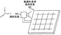
图1示出了根据各实施例的示例性触摸和悬停感测设备。Figure 1 illustrates an exemplary touch and hover sensing device in accordance with various embodiments.
图2示出了根据各实施例的可以对感测其附近的触摸进行补偿的示例性触摸和悬停感测设备。FIG. 2 illustrates an exemplary touch and hover sensing device that can compensate for sensing touches in its vicinity, according to various embodiments.
图3示出了根据各实施例的可以补偿触摸信号的示例性触摸和悬停感测设备。FIG. 3 illustrates an exemplary touch and hover sensing device that can compensate for touch signals, according to various embodiments.
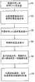
图4示出了根据各实施例的补偿触摸和悬停感测设备中的触摸信号的示例性方法。FIG. 4 illustrates an exemplary method of compensating touch signals in a touch and hover sensing device in accordance with various embodiments.
图5示出了根据各实施例的补偿触摸和悬停感测设备中的触摸信号的另一示例性方法。FIG. 5 illustrates another exemplary method of compensating touch signals in a touch and hover sensing device in accordance with various embodiments.
图6示出了根据各实施例的可以补偿触摸信号的另一示例性触摸和悬停感测设备。FIG. 6 illustrates another exemplary touch and hover sensing device that can compensate touch signals in accordance with various embodiments.
图7示出了根据各实施例的补偿触摸和悬停感测设备中的触摸信号的另一示例性方法。FIG. 7 illustrates another exemplary method of compensating touch signals in a touch and hover sensing device in accordance with various embodiments.
图8示出了根据各实施例的补偿触摸和悬停感测设备中的触摸信号的另一示例性方法。FIG. 8 illustrates another exemplary method of compensating touch signals in a touch and hover sensing device in accordance with various embodiments.
图9示出了根据各实施例的可以对感测其附近的对象进行形状改造(shape profile)的示例性触摸和悬停感测设备。FIG. 9 illustrates an exemplary touch and hover sensing device that can shape profile objects in its vicinity being sensed, in accordance with various embodiments.
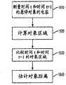
图10示出了根据各实施例的改造触摸和悬停感测设备中的对象形状的示例性方法。FIG. 10 illustrates an exemplary method of reshaping objects in a touch and hover sensing device, in accordance with various embodiments.
图11示出了根据各实施例的改造触摸和悬停感测设备中的对象形状的另一示例性方法。FIG. 11 illustrates another exemplary method of reshaping objects in a touch and hover sensing device, in accordance with various embodiments.
图12示出了根据各实施例的改造触摸和悬停感测设备中的对象形状的另一示例性方法。FIG. 12 illustrates another exemplary method of reshaping objects in a touch and hover sensing device in accordance with various embodiments.
图13示出了根据各实施例的可以对感测小的近的对象和大的远的对象彼此进行区分的示例性触摸和悬停感测设备。FIG. 13 illustrates an exemplary touch and hover sensing device that can sense small near objects and large far objects differently from each other, according to various embodiments.
图14示出了根据各实施例的可以区分小的近的对象和大的远的对象的示例性触摸和悬停感测设备。14 illustrates an example touch and hover sensing device that can distinguish between small near objects and large far objects, according to various embodiments.
图15示出了根据各实施例的可以区分小的近的对象和大的远的对象的另一示例性触摸和悬停感测设备。FIG. 15 illustrates another exemplary touch and hover sensing device that can distinguish between small near objects and large far objects, in accordance with various embodiments.
图16示出了根据各实施例的区分触摸和悬停感测设备中的小的近的对象和大的远的对象的示例性方法。FIG. 16 illustrates an exemplary method of distinguishing between small near objects and large far objects in a touch and hover sensing device, in accordance with various embodiments.
图17示出了根据各实施例的并行地感测触摸和悬停对象的示例性触摸和悬停感测设备。17 illustrates an exemplary touch and hover sensing device that senses touch and hover objects in parallel, according to various embodiments.
图18示出了根据各实施例的可以并行地感测触摸对象和悬停对象的示例性触摸和悬停感测设备。18 illustrates an exemplary touch and hover sensing device that can sense touch objects and hover objects in parallel, according to various embodiments.
图19示出了根据各实施例的并行地感测触摸和悬停感测设备中的触摸对象和悬停对象的示例性方法。FIG. 19 illustrates an exemplary method of sensing touch objects and hover objects in a touch and hover sensing device in parallel, according to various embodiments.
图20示出了根据各实施例的并行地感测触摸和悬停感测设备中的触摸对象和悬停对象的另一示例性方法。FIG. 20 illustrates another exemplary method of sensing touch objects and hover objects in parallel in a touch and hover sensing device in accordance with various embodiments.
图21示出了根据各实施例的感测多个悬停对象的示例性触摸和悬停感测设备。FIG. 21 illustrates an example touch and hover sensing device that senses multiple hovering objects, in accordance with various embodiments.
图22示出了描绘根据各实施例的触摸和悬停感测设备中的电容测量值对传感器位置的示例性图形。22 shows an exemplary graph depicting capacitive measurements versus sensor location in a touch and hover sensing device in accordance with various embodiments.
图23示出了根据各实施例的感测触摸和悬停感测设备中的多个悬停对象的示例性方法。FIG. 23 illustrates an exemplary method of sensing multiple hovering objects in a touch and hover sensing device in accordance with various embodiments.
图24示出了根据各实施例的可以补偿信号漂移的示例性触摸和悬停感测设备。FIG. 24 illustrates an exemplary touch and hover sensing device that can compensate for signal drift, according to various embodiments.
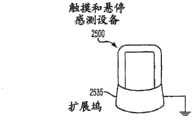
图25示出了根据各实施例的可以补偿信号漂移的另一示例性触摸和悬停感测设备。FIG. 25 illustrates another exemplary touch and hover sensing device that can compensate for signal drift, in accordance with various embodiments.
图26示出了根据各实施例的补偿信号偏移的示例性触摸和悬停感测设备。FIG. 26 illustrates an example touch and hover sensing device that compensates for signal offsets in accordance with various embodiments.
图27示出了根据各实施例的补偿触摸和悬停感测设备中的信号漂移的示例性方法。FIG. 27 illustrates an exemplary method of compensating for signal drift in a touch and hover sensing device, in accordance with various embodiments.
图28示出了根据各实施例的可以补偿传感器电阻的示例性触摸和悬停感测设备。FIG. 28 illustrates an example touch and hover sensing device that can compensate for sensor resistance, according to various embodiments.
图29示出了根据各实施例的可以补偿传感器电阻的另一示例性触摸和悬停感测设备。FIG. 29 illustrates another example touch and hover sensing device that can compensate for sensor resistance, in accordance with various embodiments.
图30示出了根据各实施例的可以补偿传感器电阻的另一示例性触摸和悬停感测设备。FIG. 30 illustrates another exemplary touch and hover sensing device that can compensate for sensor resistance, in accordance with various embodiments.
图31示出了根据各实施例的可以补偿传感器电阻的另一示例性触摸和悬停感测设备。FIG. 31 illustrates another exemplary touch and hover sensing device that can compensate for sensor resistance, in accordance with various embodiments.
图32示出了描绘根据各实施例的触摸和悬停感测设备中的电容变化对传感器位置的示例性图形。Figure 32 shows an exemplary graph depicting capacitance change versus sensor position in a touch and hover sensing device in accordance with various embodiments.
图33示出了描绘根据各实施例的补偿触摸和悬停感测设备中的电容变化对传感器位置的图形。Figure 33 shows a graph depicting capacitance changes versus sensor position in a compensated touch and hover sensing device, according to various embodiments.
图34示出了根据各实施例的补偿触摸和悬停感测设备中的作为位置的函数的电容变化的示例性方法。FIG. 34 illustrates an example method of compensating for capacitance changes as a function of position in a touch and hover sensing device, in accordance with various embodiments.
图35示出了根据各实施例的可以在触摸模式和悬停模式之间切换的示例性触摸和悬停感测设备。FIG. 35 illustrates an example touch and hover sensing device that can switch between touch mode and hover mode, according to various embodiments.
图36示出了根据各实施例的可以在触摸模式和悬停模式之间切换的另一示例性触摸和悬停感测设备。FIG. 36 illustrates another exemplary touch and hover sensing device that can be switched between touch mode and hover mode in accordance with various embodiments.
图37示出了根据各实施例的可以在触摸模式和悬停模式之间切换的另一示例性触摸和悬停感测设备。FIG. 37 illustrates another exemplary touch and hover sensing device that can be switched between touch mode and hover mode in accordance with various embodiments.
图38示出了根据各实施例的可以在触摸模式和悬停模式之间切换的另一示例性触摸和悬停感测设备。FIG. 38 illustrates another exemplary touch and hover sensing device that can be switched between touch mode and hover mode in accordance with various embodiments.
图39示出了根据各实施例的在触摸模式和悬停模式之间切换的示例性方法。Figure 39 illustrates an example method of switching between touch mode and hover mode in accordance with various embodiments.
图40示出了根据各实施例的在触摸模式和悬停模式之间切换的另一示例性方法。FIG. 40 illustrates another exemplary method of switching between touch mode and hover mode in accordance with various embodiments.
图41示出了根据各实施例的在设备触摸和悬停面板处具有接地屏蔽以最小化来自设备显示器的干扰的示例性触摸和悬停感测设备。Figure 41 illustrates an exemplary touch and hover sensing device with a ground shield at the device touch and hover panel to minimize interference from the device display, in accordance with various embodiments.
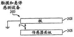
图42示出了根据各实施例的可以在设备触摸和传感器面板处最小化来自设备显示器的干扰(通过提供它们之间的最佳距离)的示例性触摸和悬停感测设备。Figure 42 illustrates an exemplary touch and hover sensing device that can minimize interference from the device display at the device touch and sensor panels by providing an optimal distance between them, according to various embodiments.
图43示出了根据各实施例的可以执行触摸和悬停感测的示例性计算系统。Figure 43 illustrates an example computing system that can perform touch and hover sensing in accordance with various embodiments.
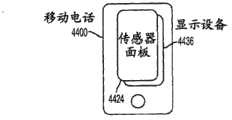
图44示出了根据各实施例的可以执行触摸和悬停感测的示例性移动电话。FIG. 44 illustrates an example mobile phone that can perform touch and hover sensing in accordance with various embodiments.
图45示出了根据各实施例的可以执行触摸和悬停感测的示例性数字媒体播放器。Figure 45 illustrates an example digital media player that can perform touch and hover sensing, in accordance with various embodiments.
图46示出了根据各实施例的可以执行触摸和悬停感测的示例性计算机。FIG. 46 illustrates an example computer that can perform touch and hover sensing, according to various embodiments.
具体实施方式Detailed ways
在下面的各实施例的描述中,将参考构成本发明的一部分的附图,并通过例图示出了其中可以实施本发明的特定实施例。可以理解,可以使用其它实施例并且可以做出结构上的改变而不背离各实施例的范围。In the following description of various embodiments, reference is made to the accompanying drawings which form a part hereof, and show by way of illustration specific embodiments in which the invention may be practiced. It is to be understood that other embodiments may be utilized and structural changes may be made without departing from the scope of the embodiments.
这涉及改善的触摸和悬停感测。可以解决触摸和悬停感测的各方面以改善对触摸和悬停事件的检测。在某些实施例中,触摸和悬停感测设备可以通过补偿感测信号中表示两个事件的触摸事件,来确保所希望的悬停事件不被附带的触摸事件(例如,手握住设备)遮蔽。相反,在某些实施例中,当悬停和触摸事件两者都是所希望的时,设备可以对其传感器和/或感测信号进行调整,以确保两种事件都被检测到。在某些实施例中,设备可以通过改造(profile)对象形状来提高其确定悬停对象正在指向的设备用户界面位置的精确度。在某些实施例中,设备可以区分对象的距离和区域(面积或大小)以便适当地处理对应的感测信号,并随后执行计划的动作。在某些实施例中,设备可以改善对并行悬停事件的检测。在某些实施例中,设备可以通过调整设备的基准电容来补偿感测信号中的信号漂移。在某些实施例中,设备可以通过对驱动设备的传感器和/或电压起伏图(voltage pattern)进行调整来补偿触摸和悬停传感器的电阻。在某些实施例中,设备可以通过作为悬停事件的位置的函数向感测信号施加增益因子,来对感测信号补偿传感器的灵敏度变化(一般而言,在涉及悬停事件过程中)。在某些实施例中,设备可以通过补偿由感测信号中的切换分量所引入的寄生电容,来改善触摸模式和悬停模式之间的传感器切换。在某些实施例中,设备可以通过减少来自显示器在传感器处的干扰来改善显示器与传感器的集成。This involves improved touch and hover sensing. Aspects of touch and hover sensing can be addressed to improve detection of touch and hover events. In some embodiments, a touch and hover sensing device can ensure that a desired hover event is not overshadowed by an incidental touch event (e.g., a hand holding the device) by compensating for touch events representing two events in the sense signal. ) shaded. Conversely, in some embodiments, when both hover and touch events are desired, the device may make adjustments to its sensors and/or sense signals to ensure that both events are detected. In some embodiments, the device can profile the object shape to improve the accuracy with which it can determine where a hovering object is pointing at the device user interface. In some embodiments, the device can distinguish the distance and area (area or size) of an object in order to properly process the corresponding sensed signal and subsequently perform the planned action. In some embodiments, the device may improve detection of parallel hover events. In some embodiments, the device can compensate for signal drift in the sensed signal by adjusting a reference capacitance of the device. In some embodiments, the device can compensate for touch and hover sensor resistance by making adjustments to the sensors and/or voltage patterns driving the device. In some embodiments, the device may compensate the sensed signal for changes in sensitivity of the sensor (generally, during a hovering event involved) by applying a gain factor to the sensed signal as a function of the position of the hovering event. In some embodiments, a device may improve sensor switching between touch and hover modes by compensating for parasitic capacitance introduced by switching components in the sense signal. In some embodiments, the device may improve display and sensor integration by reducing interference from the display at the sensor.
这些及其他方法可以有利地提供改善的触摸和悬停感测。These and other approaches can advantageously provide improved touch and hover sensing.
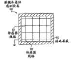
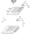
图1示出了根据各实施例的示例性触摸和悬停感测设备。在以符号方式绘制的图1的示例中,触摸和悬停感测设备100可包括传感器面板111,该传感器面板111具有可以彼此交叉以构成用于感测触摸对象和/或悬停对象的传感器的水平线路101和垂直线路102的阵列。可另选地,水平线路101和垂直线路102可以彼此靠近地排列在同一层上,而不进行直接电接触以构成传感器。基于设备100的需求,也可以使用线路101,102的其他非正交布局。水平线路101和垂直线路102可以是导电材料的导电迹线,例如氧化锡铟(ITO)。导电材料可以是透明的、半透明的、或不透明的,取决于设备100的需求。触摸和感测设备100也可以包括触摸和悬停控制系统107,该系统107可以利用向水平线路101和/或垂直线路102施加的电信号,例如交流(AC)信号,来驱动传感器面板111。传输到传感器面板111的交流信号会产生从传感器面板延伸的电场,该电场可以被用来感测在面板上方悬停或触摸面板的对象。然后,触摸和悬停控制系统107可以测量由水平线路101和/或垂直线路102上的悬停或触摸对象所引起的电容变化,以检测传感器面板111处的悬停事件或触摸事件。Figure 1 illustrates an exemplary touch and hover sensing device in accordance with various embodiments. In the example of FIG. 1, which is drawn symbolically, the touch and hover
触摸和悬停感测设备100可以基于自电容和/或互电容来操作。在自电容中,可以测量传感器面板111相对于某些参考(例如,地线)的自电容。被置于传感器面板111靠近的电场中的对象会引起传感器面板的自电容变化,该变化可以通过各种技术来测量。例如,触摸和悬停控制系统107可以驱动每条水平线路101和垂直线路102,以产生从传感器面板111延伸的电场。然后,触摸和悬停控制系统107可以测量每条水平线路101和垂直线路102上的自电容,其中,水平线路和垂直线路上的最强的测量值,例如自电容的最大变化,可以指示悬停事件或触摸事件的(x,y)位置。The touch and hover
在互电容中,可以在交叉的或附近的水平线路101和垂直线路102之间形成传感器面板111的互电容。被置于传感器面板111靠近的电场中的对象会引起传感器面板的互电容变化,该变化可以通过各种技术来测量。例如,触摸和悬停控制系统107可以驱动每条水平线路101,以产生从传感器面板111延伸的电场。然后,触摸和悬停控制系统107可以测量垂直线路102上的互电容变化,其中水平线路和垂直线路的交叉或附近位置处的最强的测量值,例如互电容的最大变化,可以指示悬停事件或触摸事件的(x,y)位置。In mutual capacitance, the mutual capacitance of the
在某些实施例中,触摸和悬停感测设备100可以使用自电容来检测悬停事件和互电容,以检测触摸事件。在其他实施例中,设备100可以使用自电容来检测所有事件。在其他实施例中,设备可以使用互电容来检测所有事件。根据设备的需求,可以使用各种电容配置。In some embodiments, the touch and hover
如此处所描述的,在某些实施例中,电容测量值可以指示绝对电容,而在某些实施例中,电容测量值可以指示电容变化。As described herein, in some embodiments capacitance measurements may indicate absolute capacitance, and in some embodiments capacitance measurements may indicate capacitance changes.
下面是根据各实施例的可以被解决以提供触摸和悬停事件的改善检测的触摸和悬停感测的各方面。The following are aspects of touch and hover sensing that can be addressed to provide improved detection of touch and hover events in accordance with various embodiments.
触摸信号补偿Touch Signal Compensation
对象触摸感测设备可以一般比对象在设备上方悬停产生更强的信号,使得当它们同时发生时触摸信号会遮蔽或以其他方式减小悬停信号的可检测性。当触摸信号只是附带的而悬停信号是有关系的时,这会特别有问题。图2示出了这样的示例。这里,用户可以利用左手212夹持触摸和悬停感测设备200,其中,拇指212-a触摸设备感测区域,同时以右手214在设备上方悬停,其中手指214-b指向设备的UI显示器上的区域以引起某个动作。由于拇指212-a触摸设备200,因此拇指附近的传感器会生成更强的信号,在某些情况下,是饱和信号。相比之下,由于手指214-b在设备200上方悬停,因此检测到手指的传感器会生成较弱的信号,在某些情况下,是弱得多的信号。为适当地恢复较弱的悬停信号,设备200可以补偿较强的触摸信号的影响。An object touching the sensing device may generally produce a stronger signal than an object hovering over the device, so that when they occur simultaneously the touch signal may obscure or otherwise reduce the detectability of the hover signal. This can be especially problematic when the touch signal is only incidental and the hover signal is related. Figure 2 shows such an example. Here, a user may hold touch and hover sensing device 200 with left hand 212, with thumb 212-a touching the device sensing area, while hovering over the device with right hand 214, with fingers 214-b pointing at the device's UI display area on the surface to cause an action. As the thumb 212-a touches the device 200, the sensors near the thumb generate a stronger, and in some cases, saturated signal. In contrast, as the finger 214-b is hovering over the device 200, the sensor that detects the finger will generate a weaker signal, and in some cases, a much weaker signal. To properly restore weaker hover signals, device 200 may compensate for the effects of stronger touch signals.
图3示出了根据各实施例的可以补偿触摸信号的示例性触摸和悬停感测设备。在图3的示例中,由触摸和悬停感测设备300中的传感器线路301,302所形成的传感器可以被分区(通过虚线以符号方式示出)为象限300-a,300-b,300-c,以及300-d,使得与这些象限中的传感器相关联的感测信号也可以被分区。具有更强的触摸信号的象限可以被检测,并与具有较弱的悬停信号的象限分离,使得可以恢复较弱的悬停信号供进一步处理,可以忽略或丢弃较强的触摸信号。在某些实施例中,分区可以以软件和/或固件来执行,其中象限可以共享传感器线路301,302。在某些替换实施例中,分区可以以硬件来进行,其中每个象限都可以具有分离的传感器线路301,302。FIG. 3 illustrates an exemplary touch and hover sensing device that can compensate for touch signals, according to various embodiments. In the example of FIG. 3 , the sensor formed by the
虽然图3的触摸和悬停感测设备被分区为象限,但是也可以分区为其他数量的分区和/或配置,只要每个分区都包括设备的用于将传感器线路连接到驱动器和感测电路的至少一个边缘。Although the touch and hover sensing device of FIG. 3 is partitioned into quadrants, it may be partitioned into other numbers of partitions and/or configurations, as long as each partition includes a device for connecting the sensor lines to the driver and sensing circuitry. at least one edge of .
图4示出了补偿图3的触摸和悬停感测设备中的触摸信号的示例性方法。在图4的示例中,可以测量每个分区中的电容(410)。可以就电容测量值是否超过预定阈值作出判断(420)。如果测量值超过阈值,指示强的或饱和信号,则可以忽略作为附带触摸信号的电容测量值,例如夹持设备的拇指(430)。否则,如果测量值不超过阈值,指示较弱的信号,则可以保留电容测量值,作为所希望的悬停信号供进一步处理,例如手指在设备上方悬停(440)。FIG. 4 illustrates an exemplary method of compensating touch signals in the touch and hover sensing device of FIG. 3 . In the example of FIG. 4, the capacitance in each partition may be measured (410). A determination may be made as to whether the capacitance measurement exceeds a predetermined threshold (420). If the measurement exceeds a threshold, indicating a strong or saturated signal, the capacitive measurement may be ignored as an incidental touch signal, such as a thumb gripping the device ( 430 ). Otherwise, if the measurement does not exceed the threshold, indicating a weaker signal, the capacitive measurement may be retained for further processing as a desired hover signal, such as a finger hovering over the device (440).
图5示出了补偿图3的触摸和悬停感测设备中的触摸信号的另一示例性方法。在图5的示例中,可以利用特定电压来驱动设备传感器线路,以便确保由传感器线路所形成的相关传感器饱和(505)。在传感器被以软件和/或固件分区的某些实施例中,到所有分区的驱动电压可以相同。在传感器被以硬件分区的某些替换实施例中,其中更有可能产生附带触摸的分区中的驱动电压可以是特定电压,以便使那些分区中的传感器饱和,而其余分区中的驱动电压可以不同,以便适当地感测手指在设备上方悬停。可以测量每个分区中的电容(510)。可以就电容测量值是否超过预定阈值作出判断(520)。如果超过,指示饱和信号,则可以作为附带触摸信号,忽略电容测量值(530)。如果不,则可以保留电容测量值,作为所希望的悬停信号,供进一步处理(540)。FIG. 5 illustrates another exemplary method of compensating touch signals in the touch and hover sensing device of FIG. 3 . In the example of FIG. 5 , device sensor lines may be driven with a specific voltage in order to ensure saturation of the associated sensors formed by the sensor lines ( 505 ). In some embodiments where the sensor is partitioned in software and/or firmware, the drive voltage to all partitions may be the same. In some alternative embodiments where the sensors are partitioned in hardware, the drive voltages in partitions where incidental touches are more likely to occur may be specific voltages to saturate the sensors in those partitions, while the drive voltages in the remaining partitions may be different , to properly sense a finger hovering over the device. Capacitance in each partition can be measured (510). A determination may be made as to whether the capacitance measurement exceeds a predetermined threshold (520). If exceeded, indicating a saturated signal, the capacitive measurement may be ignored ( 530 ) as an incidental touch signal. If not, the capacitance measurement may be retained as the desired hover signal for further processing (540).
图6示出了根据各实施例的可以补偿触摸信号的另一示例性触摸和悬停感测设备。在图6的示例中,触摸和悬停感测设备600可包括设备的边界周围的接地屏蔽610。在很多情况下,最有可能的附带触摸来自拇指或其他对象在边缘处夹持设备600。如此,边界周围的接地屏蔽610会阻止拇指或其他对象接触由传感器线路601,602所形成的设备传感器,并阻止从那里生成触摸信号。接地屏蔽610可以是耦合到地以将来自触摸对象的任何电容分流到地而并非分流到设备传感器的任何导电材料。FIG. 6 illustrates another exemplary touch and hover sensing device that can compensate touch signals in accordance with various embodiments. In the example of FIG. 6 , touch and hover
除如图3中的对设备分区或如图6中的提供接地屏蔽之外或作为其替换方案,可以操纵设备的驱动电压配置,以补偿触摸信号,如图7所描述的。In addition to or as an alternative to partitioning the device as in FIG. 3 or providing a ground shield as in FIG. 6 , the drive voltage configuration of the device can be manipulated to compensate for touch signals as described in FIG. 7 .
图7示出了根据各实施例的通过调整驱动电压的频率来补偿触摸和悬停感测设备中的触摸信号的示例性方法。由于来自传感器线路的导电材料的电阻,驱动电压沿着传感器线路传播的能力会受驱动电压的频率的影响,其中,较高的频率会比较低的频率更受传感器线路的电阻的不利影响。结果,在较高频率驱动电压时,在传感器线路开始处的传感器可以比在传感器线路末端处的传感器看到更强的驱动电压,从而生成更强的电场以及随后的更强的触摸和悬停信号。在较低频率驱动电压时,沿着传感器线路的所有传感器可以被类似地驱动,从而到处生成可接受的电场以及随后的触摸和悬停信号。传感器电阻对驱动电压频率的这个影响可以被用来补偿触摸信号。7 illustrates an exemplary method of compensating touch signals in a touch and hover sensing device by adjusting the frequency of a drive voltage, according to various embodiments. Due to the resistance of the conductive material from the sensor line, the ability of the drive voltage to propagate along the sensor line will be affected by the frequency of the drive voltage, with higher frequencies being more adversely affected by the resistance of the sensor line than lower frequencies. As a result, a sensor at the beginning of the sensor line can see a stronger drive voltage than a sensor at the end of the sensor line when driving the voltage at a higher frequency, generating a stronger electric field and subsequent stronger touches and hovers Signal. When driving the voltage at a lower frequency, all sensors along the sensor line can be driven similarly, generating acceptable electric fields and subsequent touch and hover signals everywhere. This effect of the sensor resistance on the drive voltage frequency can be used to compensate the touch signal.
在图7的示例中,传感器线路可以利用较高频率驱动电压来驱动(710)。可以测量由传感器线路所形成的传感器处的电容(720)。然后,传感器线路可以利用较低频率驱动电压来驱动(730)。可以再次测量传感器处的电容(740)。假设附带触摸更有可能在传感器线路的开始处产生,较高频率电容测量值和较低频率电容测量值可以基本上是类似的。相反,假设所希望的悬停更有可能在远离传感器线路的开始处产生,较高频率电容测量值和较低频率电容测量值可以大大地不同,较低频率电容测量值较高。相应地,可以从较低频率测量值中减去较高频率测量值,从而大大地消除附带触摸信号,并保留所希望的悬停信号(750)。In the example of FIG. 7, the sensor lines can be driven with a higher frequency drive voltage (710). Capacitance at the sensor formed by the sensor lines may be measured (720). The sensor lines can then be driven with the lower frequency drive voltage (730). The capacitance at the sensor can again be measured (740). Assuming incidental touches are more likely to occur at the beginning of the sensor lines, the higher frequency capacitance measurements and the lower frequency capacitance measurements may be substantially similar. Conversely, assuming that the desired hover is more likely to occur farther from the start of the sensor line, the higher frequency capacitance measurements and the lower frequency capacitance measurements may differ substantially, with the lower frequency capacitance measurements being higher. Accordingly, the higher frequency measurements can be subtracted from the lower frequency measurements, thereby largely canceling the incidental touch signal and preserving the desired hover signal ( 750 ).
图8示出了根据各实施例的通过从多个方向驱动设备传感器线路来补偿触摸和悬停感测设备中的触摸信号的另一示例性方法。如上文所描述的,来自传感器线路的导电材料的电阻会干扰驱动电压。通过从不同的方向来驱动传感器线路,设备可以确保合计的可接受感测信号。在图8的示例中,水平传感器线路可以交替从右侧和左侧驱动(810)。例如,最上面的水平传感器线路可以从左侧驱动,从右侧驱动下一传感器线路,依次类推。如此,由左侧驱动的传感器线路形成的传感器可以在设备的左边生成更强的信号,而由右侧驱动的传感器线路形成的传感器可以在设备的右边生成更强的信号(基于驱动电压至少在某种程度上受传感器线路的电阻不利的影响的假设)。假设附带触摸更有可能在设备左侧的传感器上产生,则由左侧驱动的传感器线路所形成的传感器的电容测量值可以指示附带触摸信号(820)。另一方面,假设所希望的悬停更有可能在设备右侧的传感器上产生,则由右侧驱动的传感器线路所形成的传感器的电容测量值可以指示所希望的悬停信号(830)。相应地,可以忽略或丢弃来自左侧驱动的传感器的电容测量值(840)。可另选地,附带触摸会更有可能在右侧的传感器上产生,以及所希望的悬停在左侧的传感器上产生。如此,可以忽略或丢弃来自右侧驱动的传感器的电容测量值(840)。8 illustrates another exemplary method of compensating touch signals in a touch and hover sensing device by driving device sensor lines from multiple directions in accordance with various embodiments. As described above, resistance from the conductive material of the sensor lines can interfere with the drive voltage. By driving the sensor lines from different directions, the device can ensure an aggregated acceptable sense signal. In the example of FIG. 8, the level sensor lines may be driven alternately from the right and left (810). For example, the top horizontal sensor line can be driven from the left, the next sensor line from the right, and so on. In this way, a sensor formed from left-hand driven sensor lines can generate a stronger signal on the left side of the device, while a sensor formed from right-driven sensor lines can generate a stronger signal on the right side of the device (based on the drive voltage at least assumed to be adversely affected to some extent by the resistance of the sensor lines). Assuming that incidental touches are more likely to occur on sensors on the left side of the device, capacitance measurements of the sensors formed by sensor lines driven on the left side may indicate incidental touch signals ( 820 ). On the other hand, assuming that the desired hover is more likely to occur on the sensor on the right side of the device, the capacitive measurement of the sensor formed by the right side driven sensor line can be indicative of the desired hover signal ( 830 ). Accordingly, capacitive measurements from left-hand driven sensors may be ignored or discarded ( 840 ). Alternatively, incidental touches would be more likely to occur on the sensor on the right, and the desired hover on the sensor on the left. As such, capacitive measurements from right side driven sensors may be ignored or discarded ( 840 ).
虽然图2到8的示例描述了附带触摸更加可能在设备的一侧产生,但是可以理解,根据各实施例,其他位置,例如顶部和底部,中心等等,也是可以的并被容易地补偿。While the examples of FIGS. 2 to 8 describe that incidental touches are more likely to occur on one side of the device, it is understood that other locations, such as top and bottom, center, etc., are possible and easily compensated for in accordance with various embodiments.
对象形状改造(profiling)Object shape transformation (profiling)
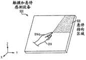
对象在感测设备上方悬停可以指向设备的UI显示器上的一个区域以引起动作。在某些情况下,在具体确定对象正在指向哪里以便引起计划的动作时会有困难。图9示出了这样的示例。这里,手914的914-b可以在触摸和悬停感测设备900上方悬停,其中,手指正在指向设备UI显示器的区域928中的某处。为帮助标识手指914-b正在指向的区域928内的哪里,可以使用与手形状改造相关联的各种方法。An object hovering over a sensing device may point to an area on the device's UI display to cause an action. In some cases, there is difficulty in determining exactly where an object is pointing in order to cause a planned action. Figure 9 shows such an example. Here, 914-b of
图10示出了根据各实施例的改造触摸和悬停感测设备中的对象形状的示例性方法。在图10的示例中,可以就悬停对象(例如手)相对于触摸和悬停感测设备的朝向作出判断,诸如对象在朝着设备的右上或左上角或中心的直立位置定向,对象在朝着设备的右下或左下角的倒立位置定向等等(1010)。可以通过例如用户输入对象朝向或者基于悬停信号来计算朝向的合适的朝向算法来作出判断。可以计算对象的质心(1020)。为计算质心,可以标识检测到悬停对象的传感器位置来确定对象区域。然后,可以使用任何合适的质心检测算法来计算对象区域的质心以及其对应的传感器位置。可以将指针设置在质心以指示对象正在指向的位置的初始估计值(1030)。指针位置可以从质心位置移到对象区域的更指示对象正在指向哪里并且是根据对象的朝向的另一传感器位置(1040)。例如,如果对象朝向设备UI显示器的右上方,则指针位置可以在右上方向从对应于确定的对象区域的质心的传感器位置移动到该区域的右上传感器位置。类似地,在另一个示例中,如果对象朝向设备UI显示器的顶部,则指针位置可以从质心位置向上移到对象区域的最上面的传感器位置。可以根据在UI显示器上的指针作出轨迹或某种其他归纳,以估计被指向的区域(1050)。FIG. 10 illustrates an exemplary method of reshaping objects in a touch and hover sensing device, in accordance with various embodiments. In the example of FIG. 10 , a determination can be made regarding the orientation of a hovering object (e.g., a hand) relative to the touch and hover sensing device, such as when the object is oriented in an upright position toward the upper right or left corner or center of the device, when the object is Orientate toward the bottom right or bottom left corner of the device in an upside-down position, etc. (1010). The determination may be made by, for example, a user inputting an object orientation or a suitable orientation algorithm calculating an orientation based on a hovering signal. The centroid of the object can be calculated (1020). To calculate the centroid, the object area can be determined by identifying the sensor location that detected the hovering object. Any suitable centroid detection algorithm may then be used to calculate the centroid of the object region and its corresponding sensor location. A pointer may be set at the centroid to indicate an initial estimate of where the object is pointing (1030). The pointer position may be moved from the centroid position to another sensor position of the object area that is more indicative of where the object is pointing and is based on the object's orientation ( 1040 ). For example, if the object is towards the upper right of the device UI display, the pointer position may be moved in the upper right direction from the sensor position corresponding to the centroid of the determined object area to the upper right sensor position of the area. Similarly, in another example, if the object is towards the top of the device UI display, the pointer position may be moved up from the centroid position to the uppermost sensor position of the object area. A trajectory or some other generalization may be made from the pointer on the UI display to estimate the pointed area (1050).
在某些实施例中,当触摸和悬停感测设备被保持在大体上直立的姿势时,可以使用设备中的加速度计或类似的检测器来确定向哪里移动指针位置(1040)。例如,加速度计可以检测重力相对于设备的方向。假设指向设备的对象是右侧向上并且不向下,则指针位置可以从质心位置移到与重力相反的方向的另一传感器位置。然后,可以使用偏移的指针来估计UI显示器上的被指向区域(1050)。In some embodiments, when the touch and hover sensing device is held in a generally upright posture, an accelerometer or similar detector in the device may be used to determine where to move the pointer position (1040). For example, an accelerometer can detect the orientation of gravity relative to the device. Assuming the object pointing at the device is right side up and not down, the pointer position can be moved from the center of mass position to another sensor position in the opposite direction of gravity. The offset pointer can then be used to estimate the pointed area on the UI display (1050).
图11示出了根据各实施例的改造触摸和悬停感测设备中的对象形状的另一示例性方法。在图11的示例中,可以基于悬停信号确定悬停对象(例如手)的形状(1110)。例如,检测到悬停对象的传感器位置可以被任何合适的形状标识算法用来确定对象的区域,因此亦可确定其形状。可以计算对象的质心(1120)。可以使用任何合适的质心检测算法来计算确定的区域的质心以及其对应的传感器位置。可以将指针设置在质心,以指示对象正在指向的位置的初始估计值(1130)。指针位置可以从质心位置移到对象区域的更指示对象正在指向哪里并且是根据对象区域的形状的另一传感器位置(1140)。例如,如果对象形状具有朝向设备UI显示器的右上方的扩展部分,则指针位置可以从质心移到对象区域的右上方的传感器位置。可以根据UI显示器上的偏移的指针作出轨迹或某种其他归纳,以估计被指向的区域(1150)。FIG. 11 illustrates another exemplary method of reshaping objects in a touch and hover sensing device, in accordance with various embodiments. In the example of FIG. 11 , the shape of a hovering object (eg, a hand) may be determined based on the hovering signal ( 1110 ). For example, the location of a sensor at which a hovering object is detected may be used by any suitable shape identification algorithm to determine the region of the object, and thus its shape. The centroid of the object may be calculated (1120). The centroids of the determined regions and their corresponding sensor positions may be calculated using any suitable centroid detection algorithm. A pointer may be set at the centroid to indicate an initial estimate of where the object is pointing (1130). The pointer position may be moved from the centroid position to another sensor position of the object area that is more indicative of where the object is pointing and according to the shape of the object area ( 1140 ). For example, if the object shape has an extended portion towards the upper right of the device UI display, the pointer position may be moved from the centroid to the sensor position at the upper right of the object area. A trajectory or some other generalization may be made from the offset pointer on the UI display to estimate the pointed area (1150).
在某些实施例中,可以对确定的对象区域中的悬停信号进行曲线拟合,以确定指示对象与触摸和悬停感测设备最近的部分以及相应地对象正在指向哪里的信号最大值。相应地,指针位置可以从质心位置移到对应于信号最大值的传感器位置(1140)。然后,可以使用偏移的指针来估计UI显示器上的被指向区域(1150)。In some embodiments, a curve fit may be performed on the hover signal in the determined object region to determine a signal maximum indicating the portion of the object closest to the touch and hover sensing device and accordingly where the object is pointing. Accordingly, the pointer position may be moved from the centroid position to the sensor position corresponding to the signal maximum (1140). The offset pointer can then be used to estimate the pointed area on the UI display (1150).
图12示出了根据各实施例的改造触摸和悬停感测设备中的对象形状的另一示例性方法。在图12的示例中,悬停对象(例如手)相对于设备的运动可以被用来确定对象正在指向哪里。可以测量时间t和t+1的电容,以检测那些时间的悬停对象(1210)。可以比较测量值来估计悬停对象的运动方向(1220)。例如,可以使用检测到对象的传感器位置来确定时间t和t+1的对象位置。然后,可以根据任何合适的运动检测算法,使用时间t和t+1之间的位置的偏移来确定对象运动方向。可以计算时间t+1测量值的质心(1230)。例如,可以使用对应于对象的传感器位置来确定对象区域。然后,可以使用任何合适的质心检测算法来计算对象区域的质心以及其对应的传感器位置。可以将指针设置在质心以指示对象正在指向的位置的初始估计值(1240)。指针位置可以从确定的运动方向中的质心位置移到对象区域的更指示对象正在指向哪里的并且是根据对象的运动的另一传感器位置(1250)。例如,如果对象正在朝向UI显示器的顶部在向上的方向移动,则指针位置可以在向上的方向从质心位置移动到对象区域的最上面的传感器位置。可以根据设备UI显示器上的偏移的指针作出轨迹或某种其他归纳,以估计被指向的区域(1260)。FIG. 12 illustrates another exemplary method of reshaping objects in a touch and hover sensing device in accordance with various embodiments. In the example of FIG. 12, the motion of a hovering object (eg, a hand) relative to the device can be used to determine where the object is pointing. Capacitance at times t and t+1 may be measured to detect hovering objects at those times ( 1210 ). The measurements may be compared to estimate the direction of motion of the hovering object (1220). For example, the location of the object at times t and t+1 may be determined using the sensor location at which the object was detected. The offset in position between time t and t+1 can then be used to determine the object motion direction according to any suitable motion detection algorithm. The centroid of the time t+1 measurement may be calculated (1230). For example, the object area may be determined using sensor locations corresponding to the object. Any suitable centroid detection algorithm may then be used to calculate the centroid of the object region and its corresponding sensor location. A pointer may be set at the centroid to indicate an initial estimate of where the object is pointing (1240). The pointer position may be moved from the centroid position in the determined direction of motion to another sensor position of the object area that is more indicative of where the object is pointing and is based on the motion of the object (1250). For example, if the object is moving in an upward direction towards the top of the UI display, the pointer position may move in an upward direction from the centroid position to the uppermost sensor position of the object area. A trajectory or some other generalization may be made from the offset pointer on the device UI display to estimate the pointed area (1260).
可以理解,根据设备的需求也可以使用其他方法来改造对象形状。It can be understood that other methods can also be used to modify the shape of the object according to the requirements of the device.
距离和区域区分distance and area
较小的对象靠近感测设备和较大的对象远离感测设备可以生成类似的感测信号,使得难以基于信号来区分它们以确定它们的区域和/或与设备的距离,这会对随后的设备动作产生不利的影响。图13示出了这样的示例。这里,具有区域a的较小的对象1314可以位于离触摸和悬停感测设备1300的距离d处,而具有区域A的较大的对象1324可以位于离设备的距离D处,其中,A>a,并且D>d。然而,较小的对象1314的悬停信号1312可以基本上与较大的对象1324的悬停信号1322相同,使得相应的距离d和D以及区域a和A的差异不可辩别。Smaller objects approaching the sensing device and larger objects moving away from the sensing device can generate similar sensing signals, making it difficult to distinguish them based on the signal to determine their area and/or distance from the device, which can have consequences for subsequent The operation of the equipment will have an adverse effect. Figure 13 shows such an example. Here, a
图14示出了根据各实施例的可以区分小的近的对象和大的远的对象的示例性触摸和悬停感测设备。在图14的示例中,视频捕捉设备1430可以被安置在触摸和悬停感测设备1400的传感器线路附近的位置,以捕捉悬停对象的图像和/或视频。然后,捕捉到的图像和/或视频可以被用来确定对象的距离和区域。可以使用任何合适的图像/视频对象识别算法,根据捕捉到的图像和/或视频中的对象和设备位置,来确定对象与触摸和悬停感测设备的距离。可以使用任何合适的图像/视频对象识别算法,根据捕捉到的图像和/或视频中的对象的大小,来确定对象的区域。视频捕捉设备的示例可包括静物照相机、摄像机等等。在某些实施例中,捕捉设备1430可以与触摸和悬停感测设备1400集成。在其他实施例中,捕捉设备1430可以与触摸和悬停感测设备1400是分离的,并在其附近。14 illustrates an example touch and hover sensing device that can distinguish between small near objects and large far objects, according to various embodiments. In the example of FIG. 14 ,
图15示出了根据各实施例的可以区分小的近的对象和大的远的对象的另一示例性触摸和悬停感测设备。在图15的示例中,检测器1530可以被安置在触摸和悬停感测设备1500的传感器线路的附近的位置,以检测悬停对象。可以使用任何合适的信号处理算法,根据检测器的信号的各种特征,来确定对象的距离和区域。检测器的示例可包括声纳、红外线、光学、无线电等等。在某些实施例中,检测器1530可以与触摸和悬停感测设备1500集成。在其他实施例中,检测器1530可以与触摸和悬停感测设备1500是分离的,并在其附近。FIG. 15 illustrates another exemplary touch and hover sensing device that can distinguish between small near objects and large far objects, in accordance with various embodiments. In the example of FIG. 15 , a
除使用捕捉设备和检测器之外或作为其替换方案,还可以使用感测信号来区分对象的距离和区域,如图16所描述的。In addition to or as an alternative to using capture devices and detectors, sensing signals may be used to differentiate distance and area of objects, as depicted in FIG. 16 .
图16示出了根据各实施例的触摸和悬停感测设备中的使用感测信号来区分小的近的对象和大的远的对象的示例性方法。在图16的示例中,可以测量时间t和t+1的电容,以检测那些时间的悬停对象(1610)。可以使用测量值来确定对象区域(1620)。例如,可以使用检测到对象的传感器位置来确定时间t和t+1的对象区域。可以将区域进行比较,来确定从时间t到时间t+1的区域变化(1630)。基于区域的变化,可以估计对象的距离(1640)。确定的对象区域(例如时间t+1的)以及估计的距离中的一个可以被用于随后的设备动作中,例如选择显示器用户界面上的元素。FIG. 16 illustrates an exemplary method of using sense signals to distinguish small near objects from large far objects in a touch and hover sensing device according to various embodiments. In the example of FIG. 16, the capacitance at times t and t+1 may be measured to detect hovering objects at those times (1610). The object area may be determined using the measurements (1620). For example, the object area at time t and t+1 may be determined using the sensor position at which the object was detected. The regions may be compared to determine a change in region from time t to time t+1 (1630). Based on the change in area, the distance of the object can be estimated (1640). One of the determined object area (eg at time t+1) and the estimated distance may be used in a subsequent device action, eg selecting an element on the display user interface.
可以理解,根据各实施例,可以使用其他方法来基于对象感测信号,确定对象的区域和距离。It is understood that other methods may be used to determine the area and distance of the object based on the object sensing signal according to various embodiments.
并行触摸和悬停Parallel touch and hover
如上所述,对象触摸感测设备可以一般比对象在设备上方悬停产生更强的信号,使得当它们同时发生时触摸信号会遮蔽或以其他方式减小悬停信号的可检测性。与图2的实例不同,在此情况下,触摸信号与悬停信号一起是故意的并且是需要的。因此,较强的触摸信号遮蔽较弱的悬停信号会有问题。图17示出了这样的示例。这里,用户可以利用左手1712来夹持触摸和悬停感测设备1700,使用拇指1712-a来触摸设备感测区域以提供触摸输入,同时利用右手1714在设备上方悬停,使用手指1714-b来指向设备的UI显示器上的区域,以提供悬停输入,其中触摸和悬停输入可以一起起作用以导致某些动作。由于拇指1712-a触摸设备1700,因此拇指附近的传感器会生成更强的信号,在某些情况下,是饱和信号。而由于手指1714-b在设备1700上方悬停,因此传感器检测手指会生成较弱的信号,在某些情况下,是更弱的信号。可以对设备和/或信号作出某些调整,以确保触摸信号和悬停信号两者被并行地感测。As noted above, an object touching a sensing device may generally produce a stronger signal than an object hovering over the device such that when they occur simultaneously the touch signal may obscure or otherwise reduce the detectability of the hover signal. Unlike the example of Figure 2, in this case the touch signal is intentional and required along with the hover signal. Therefore, it would be problematic for a stronger touch signal to obscure a weaker hover signal. Figure 17 shows such an example. Here, the user may hold touch and hover
并行的触摸和悬停感测的示例应用可包括使用拇指触摸来选择改变到设备的特定操作模式的按钮,同时使用手指悬停来选择在该操作模式下执行的动作。An example application of parallel touch and hover sensing may include using a thumb touch to select a button that changes to a particular mode of operation of the device while using a finger hover to select an action to perform in that mode of operation.
图18示出了根据各实施例的可以并行地感测触摸对象和悬停对象的示例性触摸和悬停感测设备。在图18的示例中,触摸和悬停感测设备1800可以被分区(通过虚线以符号方式示出)为象限1800-a,1800-b、1800-c和1800-d,使得与这些象限中的传感器相关联的感测信号也可以被分区。具有更强的触摸信号的象限可以是可检测的,并与具有较弱的悬停信号的象限分开,使得触摸信号和悬停信号两者都可以被恢复,以便进行进一步处理。其中更有可能产生触摸信号的象限中的一个或多个可以被指定为触摸象限。类似地,其中更有可能产生悬停信号的象限中的一个或多个可以被指定为悬停象限。某些象限也可以被指示为其中可能产生触摸或者悬停信号的双象限。在此示例中,最左边的象限被指定为触摸象限,因为用户更有可能在此区域夹持设备1800,并使用夹持手的拇指来提供触摸输入。其余的象限被指定为悬停象限,因为用户更有可能利用指向手或其他对象来指向在这些区域的设备UI显示。在某些实施例中,分区可以以软件和/或固件来执行,其中象限可以共享传感器线路(未示出)。在某些替换实施例中,分区可以以硬件来进行,其中每个象限都可以具有分离的传感器线路。为确保触摸和悬停信号两者都被适当地感测,设备1800可以在互电容模式下操作,其中传感器线路测量互电容。可另选地,在某些实施例中,设备1800可以在自电容模式下操作,并使用与如上文所描述的方法类似的方法来检测但是与悬停信号一起保留触摸信号。18 illustrates an exemplary touch and hover sensing device that can sense touch objects and hover objects in parallel, according to various embodiments. In the example of FIG. 18 , touch and hover
虽然图18的触摸感测设备被分区为象限,但是也可以分区为其他数量的分区和/或配置,只要每个分区都包括设备的用于将传感器线路连接到驱动和感测电路的至少一个边缘。Although the touch-sensing device of FIG. 18 is partitioned into quadrants, it may be partitioned into other numbers of partitions and/or configurations as long as each partition includes at least one of the device's components for connecting sensor lines to drive and sense circuits. edge.
图19示出了使用图18的设备来并行地感测触摸对象和悬停对象的示例性方法。在图19的示例中,分区可以分别基于在该分区产生触摸、悬停、或两者的可能性,被指定为触摸分区、悬停分区和/或双分区(1910)。可以测量每个分区中互电容(1920)。在大多数情况下,互电容感测可以比自电容感测更容易地检测到多个对象,例如并行触摸和悬停对象。指示检测到的对象的指定触摸分区中的测量值可以被标识为触摸信号;而指示检测到的对象的指定悬停分区中的测量值可以被标识为悬停信号(1930)。在双分区中检测到的信号的情况下,在某些实施例中,信号可以作为不能确定的而被忽略或丢弃。在其他实施例中,可以将信号的大小与预定阈值进行比较,如果高出阈值,则将其视为触摸信号,如果等于或低于阈值,则将其视为悬停信号。FIG. 19 illustrates an example method of sensing touch objects and hover objects in parallel using the device of FIG. 18 . In the example of FIG. 19 , partitions may be designated as touch partitions, hover partitions, and/or dual partitions based on the likelihood of a touch, hover, or both, respectively, at that partition ( 1910 ). Mutual capacitance in each partition may be measured (1920). In most cases, mutual capacitance sensing can detect multiple objects more easily than self-capacitance sensing, such as touching and hovering objects in parallel. Measurements in designated touch partitions indicative of detected objects may be identified as touch signals; and measurements in designated hover partitions indicative of detected objects may be identified as hover signals (1930). In the case of a signal detected in a dual partition, in some embodiments, the signal may be ignored or discarded as indeterminate. In other embodiments, the magnitude of the signal may be compared with a predetermined threshold, and if above the threshold, it is considered a touch signal, and if it is equal to or below the threshold, it is considered a hover signal.
图20示出了根据各实施例的并行地感测触摸和悬停感测设备中的触摸对象和悬停对象的另一示例性方法。这里,设备可以被分区,但是不必分区。在图20的示例中,尽管在设备上有触摸,但是可以测量电容(2005)。如果测量值使传感器线路饱和,则测量值可以被指定为触摸饱和信号(2010)。可以基于饱和的测量值来重新校准设备,以便设备上的随后触摸不会使传感器线路饱和(2020)。在某些实施例中,为重新校准设备,驱动传感器的电压的振幅可以与触摸饱和信号成比例地减小,以便提供不饱和的电容测量值。在某些实施例中,为重新校准设备,电容测量值可以与触摸饱和信号成比例地减小,以便提供不饱和的电容测量值。在重新校准过程中,可以采取措施,以平衡使触摸信号不饱和与可观地减小悬停信号的可检测性以及信号的总的信噪比。在重新校准之后,随后的触摸信号可以是不饱和的,并且与悬停信号一起是可检测的(2030)。FIG. 20 illustrates another exemplary method of sensing touch objects and hover objects in parallel in a touch and hover sensing device in accordance with various embodiments. Here, devices can be partitioned, but need not be partitioned. In the example of Figure 20, despite a touch on the device, capacitance can be measured (2005). If the measurement saturates the sensor line, the measurement may be designated as a touch saturation signal (2010). The device may be recalibrated based on the saturation measurement so that subsequent touches on the device do not saturate the sensor lines (2020). In some embodiments, to recalibrate the device, the amplitude of the voltage driving the sensor may be reduced proportionally to the touch saturation signal in order to provide a capacitive measurement that does not saturate. In some embodiments, to recalibrate the device, the capacitance measurement may be reduced proportionally to the touch saturation signal to provide a non-saturated capacitance measurement. During the recalibration process, steps can be taken to balance desaturating the touch signal with appreciably reducing the detectability of the hover signal and the overall signal-to-noise ratio of the signal. Subsequent touch signals may be desaturated and detectable together with hover signals after recalibration (2030).
可以理解,根据各实施例,也可以使用用于检测并行悬停和触摸事件的其他方法。It will be appreciated that other methods for detecting concurrent hover and touch events may also be used in accordance with various embodiments.
多悬停检测Multiple hover detection
对于需要多个输入的设备动作,检测感测设备中的多个悬停对象是合乎需要的。图21示出了这样的示例。这里,手指2112-b可以悬停在触摸和悬停感测设备2100的一个区域上方,而手指2114-b可以悬停在设备的另一区域上方。然后,设备2100可以检测两个手指,并生成悬停信号供进一步处理。For device actions that require multiple inputs, it is desirable to detect multiple hovering objects in a sensing device. Figure 21 shows such an example. Here, finger 2112-b may hover over one area of touch and hover
图22示出了根据各实施例的从触摸和悬停感测设备中的多个悬停对象生成的悬停信号的示例性图形。在图22的示例中,沿着传感器线路的电容测量值可以在悬停对象附近的传感器位置具有峰值。可以处理测量值,以确定悬停对象的悬停信号,例如如图23所示。在某些实施例中,为确保多个悬停信号被适当地感测,设备可以在互电容模式下操作。22 illustrates an example graph of hover signals generated from multiple hovering objects in a touch and hover sensing device, in accordance with various embodiments. In the example of FIG. 22, capacitance measurements along a sensor line may have peaks at sensor locations near a hovering object. The measurements may be processed to determine a hover signal for a hovering object, such as shown in FIG. 23 . In some embodiments, to ensure that multiple hover signals are properly sensed, the device may operate in a mutual capacitance mode.
在图23的示例中,可以测量电容(2310)。可以标识指示多个悬停对象的电容测量值中的峰值(2320)。可以使用任何合适的峰值检测算法来标识峰值。可以忽略或丢弃某些杂散或小的标识的峰值来防止假检测。每个标识的峰值可以被视为悬停对象的悬停信号,并保留供进一步处理(2330)。In the example of FIG. 23, capacitance may be measured (2310). Peaks in capacitance measurements indicative of multiple hovering objects may be identified (2320). Peaks may be identified using any suitable peak detection algorithm. Certain spurious or small identified peaks can be ignored or discarded to prevent false detections. Each identified peak may be considered a hover signal for the hovering object and retained for further processing (2330).
在某些实施例中,触摸和悬停感测设备可以被分区为象限(或其他分区),以便可以在每个象限中实现多悬停,从而增大可以检测到的悬停对象的数量。In some embodiments, touch and hover sensing devices can be partitioned into quadrants (or other partitions) so that multiple hovers can be implemented within each quadrant, thereby increasing the number of hovering objects that can be detected.
信号漂移补偿Signal Drift Compensation
当感测设备遇到环境变化,例如环境温度、湿度或压力的变化;操作变化,例如组件启动、关闭、操作延长或噪声;或机械变化,例如组件偏移、膨胀或收缩时,设备的基准电容可以随着时间而变化。基准电容是指当在设备处没有触摸或悬停时设备的电容。结果,指示设备上的触摸或悬停的电容测量值可以类似地变化。这被称为信号漂移。信号漂移会对产生设备动作不利的影响,特别是当动作对特定电容测量值或特定电容值的范围敏感时。为补偿信号漂移,可以周期性地复位基准电容,以考虑任何环境、操作、机械的及其他变化。然后,可以向触摸或悬停电容测量值应用新基准,以校正测量值。When the sensing device encounters environmental changes, such as changes in ambient temperature, humidity, or pressure; operational changes, such as component startup, shutdown, prolonged operation, or noise; or mechanical changes, such as component shifting, expansion, or contraction, the device’s baseline Capacitance can change over time. The baseline capacitance refers to the capacitance of the device when there is no touch or hover at the device. As a result, capacitive measurements indicating a touch or hover on the device may vary similarly. This is called signal drift. Signal drift can adversely affect device operation, especially when the operation is sensitive to specific capacitance measurements or ranges of specific capacitance values. To compensate for signal drift, the reference capacitor can be reset periodically to account for any environmental, operational, mechanical and other changes. A new baseline can then be applied to the touch or hover capacitance measurements to correct the measurements.
图24示出了根据各实施例的可以补偿信号漂移的示例性触摸和悬停感测设备。在图24的示例中,触摸和悬停感测设备2400可包括触摸和悬停传感器面板2426和盖板2428。面板2426可包括用于生成指示触摸对象和/或悬停对象的电容测量值的传感器线路。板2428可以接地,并可以在与面板的距离d处覆盖面板2426。板2428可以是例如在用户临时用完设备2400之后可以拉开或滑动面板2426的设备盖子。可另选地,板2428可以是例如外壳的一侧,用户可以在用户临时用完设备2400之后将设备2400放入外壳中供存储或携带。在这些停用的时段,设备可以补偿信号漂移。例如,当板2428覆盖面板2426时,触摸对象或悬停对象中两者都不可能在面板处(因为面板不能在原位与板一起使用),以便面板上的传感器线路中的任何电容变化会只由于或基本上由于信号漂移。可以获取电容测量值,并可以以测量值作为新基准来校准面板2426。当板2428不覆盖面板2426时,触摸或悬停对象更加可能在面板中,以便复位基准电容可以被挂起,直到板再次覆盖面板。FIG. 24 illustrates an exemplary touch and hover sensing device that can compensate for signal drift, according to various embodiments. In the example of FIG. 24 , touch and hover
图25示出了根据各实施例的可以补偿信号漂移的另一示例性触摸和悬停感测设备。在图25的示例中,触摸和悬停感测设备2500可以位于扩展坞2535中。扩展坞2535可以接地。当设备2500被对接时,触摸对象或悬停对象两者都不可能在设备中,以便设备2500中的任何电容变化会只由于或基本上由于信号漂移。可以获取电容测量值,并可以以测量值作为新基准来校准设备2500。当设备2500被脱离时,触摸或悬停对象更加可能在设备上,以便复位基准电容可以被挂起,直到设备被再次对接。FIG. 25 illustrates another exemplary touch and hover sensing device that can compensate for signal drift, in accordance with various embodiments. In the example of FIG. 25 , touch and hover
在某些实施例中,触摸和悬停感测设备可以不具有盖子或者扩展坞。在这样的实施例中,当没有检测到触摸或悬停时,可以获取电容测量值,并可以以测量值作为新基准来校准设备。当设备空闲了比较长的时间,当设备正在使用中但是在触摸或悬停检测之间,或在某些非触摸或非悬停情况下时,这可以进行。In some embodiments, the touch and hover sensing device may not have a cover or docking station. In such an embodiment, when no touch or hover is detected, capacitive measurements may be taken and the device may be calibrated using the measurements as a new baseline. This can be done when the device has been idle for an extended period of time, when the device is in use but between touch or hover detections, or in certain non-touch or non-hover situations.
可另选地,并非等到在设备处没有触摸或悬停,可以在触摸或悬停过程中设置新基准电容。图26示出了这样的示例。这里,在手指2614-b在预先确定的时间段内触摸“触摸和悬停感测设备”2600而没有移动时,可以在该时间段内获取电容测量值,以确定电容如何随着时间的推移而漂移。该漂移的平均值可以是新基准。类似地,可以使用手指悬停而非移动来复位基准电容。Alternatively, instead of waiting until there is no touch or hover at the device, the new reference capacitance can be set during the touch or hover. Figure 26 shows such an example. Here, when finger 2614-b touches "touch and hover sensing device" 2600 for a predetermined period of time without moving, capacitance measurements can be taken during that period of time to determine how capacitance changes over time. And drift. The average of this drift can be the new baseline. Similarly, the reference capacitance can be reset using a finger hover rather than movement.
图27示出了根据各实施例的补偿触摸和悬停感测设备中的信号漂移的示例性方法。在图27的示例中,可以就在触摸和悬停感测设备处是否有触摸或悬停作出判断(2710)。在某些实施例中,用户可以输入没有触摸或悬停的指示或者复位基准电容的指示。在某些实施例中,触摸和悬停感测设备可以确定在设备处没有触摸或悬停,例如通过检测设备上的盖板(如在图24中),扩展坞中的设备(如在图25中),或指示非触摸和非悬停条件的某种其他设备参数。FIG. 27 illustrates an exemplary method of compensating for signal drift in a touch and hover sensing device, in accordance with various embodiments. In the example of FIG. 27, a determination may be made as to whether there is a touch or a hover at the touch and hover sensing device (2710). In some embodiments, the user may input an indication of no touch or hover, or an indication of reset baseline capacitance. In some embodiments, the touch and hover sensing device can determine that there is no touch or hover at the device, such as by detecting a cover on the device (as in FIG. 24 ), a device in a dock (as in FIG. 25), or some other device parameter indicating the non-touch and non-hover conditions.
如果在设备处没有触摸或悬停,则可以就设备是否基本上是固定的作出判断(2715)。通常,基本上固定的设备是更希望的,以复位基准电容,从而避免电容测量值受设备运动的不利的影响。可以使用任何合适的运动检测器或检测算法,根据设备的需求,来确定设备的运动。如果设备正在移动,则复位基准电容可以被挂起,直到条件更有利。如果设备没在移动,则可以获取电容测量值以补偿信号漂移(2720)。可以就电容测量值是否指示某些不能接受的条件,例如测量值是负的或者在负方向漂移,来作出判断(2725)。如果这样的话,则复位基准电容可以被挂起,直到条件更有利。否则,如果电容测量值是可接受的,则测量值可以被设置为设备的新基准电容,从而补偿信号漂移(2730)。If there is no touch or hover at the device, a determination may be made as to whether the device is substantially stationary (2715). In general, a substantially stationary device is more desirable to reset the reference capacitance so as to avoid capacitance measurements being adversely affected by movement of the device. Motion of the device may be determined using any suitable motion detector or detection algorithm, depending on the requirements of the device. If the device is moving, resetting the reference capacitance can be suspended until conditions are more favorable. If the device is not moving, capacitance measurements may be taken to compensate for signal drift (2720). A determination may be made (2725) as to whether the capacitance measurement indicates some unacceptable condition, such as the measurement being negative or drifting in a negative direction. If so, resetting the reference capacitance can be suspended until conditions are more favorable. Otherwise, if the capacitance measurement is acceptable, the measurement may be set as a new reference capacitance for the device, thereby compensating for signal drift (2730).
如果在设备处有触摸或悬停,则可以就触摸或悬停对象是否基本上是固定的作出判断(2750)。如果没有,则设备可能在操作中,或者对象正在摇动,以便复位基准可以被挂起,直到条件是更有利的。如果触摸或悬停对象基本上是固定的,则对象可能触摸或悬停,以复位基准电容(如在图26中那样)。可以在设备中测量电容(2755)。可以就电容测量值是否指示某些不能接受的条件,例如测量值是负的或者在负方向漂移,来作出判断(2760)。如果这样的话,则复位基准电容可以被挂起,直到条件更有利。否则,如果电容测量值是可接受的,则可以就与复位的基准电容相关联的预先确定的时间段是否已经到期作出判断(2765)。如果该时间段没有到期,则可以获取额外的电容测量值,只要对象保持固定(2750-2765)。如果该时间段已经到期,则可以对在预先确定的时间段内获取的电容测量值进行平均(2770)。该平均值可以被设置为设备的新基准电容,从而补偿信号漂移(2775)。If there is a touch or hover at the device, a determination may be made as to whether the touch or hover object is substantially stationary (2750). If not, the equipment may be in operation, or the object is being shaken, so resetting the baseline can be suspended until conditions are more favorable. If the touching or hovering object is substantially stationary, the object may be touched or hovered to reset the reference capacitance (as in Figure 26). Capacitance can be measured in the device (2755). A determination may be made (2760) as to whether the capacitance measurement indicates some unacceptable condition, such as the measurement being negative or drifting in a negative direction. If so, resetting the reference capacitance can be suspended until conditions are more favorable. Otherwise, if the capacitance measurement is acceptable, a determination may be made as to whether a predetermined period of time associated with the reset baseline capacitance has expired (2765). If the time period has not expired, additional capacitance measurements can be taken as long as the subject remains stationary (2750-2765). If the time period has expired, the capacitance measurements taken over the predetermined time period may be averaged (2770). This average may be set as a new reference capacitance for the device, thereby compensating for signal drift (2775).
在某些实施例中,用户可以手动输入新基准电容,以补偿信号漂移。In some embodiments, a user can manually enter a new reference capacitance to compensate for signal drift.
在基准电容被复位之后,可以测量指示设备处的触摸或者悬停的电容(2780)。可以从电容测量值中减去补偿信号漂移的新基准电容,以作为触摸或悬停的结果,来确定电容变化(2785)。After the reference capacitance is reset, the capacitance of the touch or hover at the pointing device may be measured (2780). A new reference capacitance that compensates for signal drift may be subtracted from the capacitance measurement to determine capacitance change as a result of the touch or hover (2785).
可以理解,还可以使用其他方法来复位基准电容,以根据设备的需求,补偿信号漂移。It can be understood that other methods can also be used to reset the reference capacitor, so as to compensate for signal drift according to the requirements of the device.
传感器电阻补偿Sensor Resistance Compensation
如上所述,由于触摸和悬停感测设备传感器线路的导电材料的电阻,驱动电压以沿着传感器线路传播的能力会受驱动电压的频率的影响,其中,较高的频率比较低的频率具有更大的困难。结果,在较高频率驱动电压时,传感器线路的开始处的传感器可以比传感器线路的末端处的传感器看到更强的驱动电压,从而生成更强的电场以及随后的触摸和悬停信号。在较低频率驱动电压时,沿着传感器线路的所有传感器可以被类似地驱动,从而到处生成可接受的电场以及随后的触摸和悬停信号。尽管较高频率驱动电压是希望的,但是较大的触摸和悬停感测设备沿着比较长的传感器线路驱动所有传感器会有困难。为补偿传感器线路的电阻,可以使用各种传感器配置,如下面所描述的。As mentioned above, due to the resistance of the conductive material of the touch and hover sensing device sensor lines, the ability of the drive voltage to propagate along the sensor lines can be affected by the frequency of the drive voltage, where higher frequencies have a greater impact than lower frequencies. greater difficulty. As a result, at higher frequency drive voltages, sensors at the beginning of the sensor line can see a stronger drive voltage than sensors at the end of the sensor line, generating stronger electric fields and subsequent touch and hover signals. When driving the voltage at a lower frequency, all sensors along the sensor line can be driven similarly, generating acceptable electric fields and subsequent touch and hover signals everywhere. While higher frequency drive voltages are desirable, larger touch and hover sensing devices can have difficulty driving all of the sensors along relatively long sensor lines. To compensate for the resistance of the sensor lines, various sensor configurations can be used, as described below.
图28示出了根据各实施例的可以补偿传感器电阻的示例性触摸和悬停感测设备。在图28的示例中,触摸和悬停感测设备2800的相邻的传感器线路2801-a到2801-d可以分组(gang)在一起以降低传感器电阻。分组传感器线路2801-a和2801-b可以有效地构成单个传感器线路2810-a,线路的单个电阻现在并联,从而使分组的线路的总电阻减半。传感器线路2801-c和2801-d可以类似地分组在一起,以构成单个传感器线路2810-b。分组还可以通过将两个传感器线路组合为一个来降低设备2800的分辨率。相应地,降低电阻以产生较强的信号可以与降低那些信号的分辨率保持平衡。因此,可以确定分组的量,以便减小传感器线路的电阻,同时维护适当的感测分辨率。FIG. 28 illustrates an example touch and hover sensing device that can compensate for sensor resistance, according to various embodiments. In the example of FIG. 28, adjacent sensor lines 2801-a through 2801-d of touch and hover
在此示例中,水平传感器线路被分组在一起。然而,可以理解,垂直传感器线路可以根据设备的需求,类似地分组在一起。In this example, the level sensor lines are grouped together. However, it is understood that the vertical sensor lines can be similarly grouped together according to the needs of the device.
图29示出了根据各实施例的可以补偿传感器电阻的另一示例性触摸和悬停感测设备。在图29的示例中,触摸和悬停感测设备2900可以根据悬停对象2914的距离来动态地分组传感器线路。设备2900对对象2914的灵敏度可以是对象的区域和距离的函数。当对象2914较远,在距离D处时,其区域可以较小,以便设备2900处的电容测量值可以较小。更高的传感器分辨率可以是首选的,以适当地感测远的对象。相应地,传感器线路2901-a到2901-d可以保持分离,以提供更高的分辨率。相反,当对象2914较近,在距离d时,其区域可以较大,以便设备2900处的电容测量值可以较大。较低的传感器分辨率仍可以适当地感测对象。相应地,传感器线路2901-a和2901-b可以被分组在一起,作为单个传感器线路2910-a,而传感器线路2901-c和2901-d可以被分组在一起,作为传感器线路2910-b,以实现较低的传感器电阻。可以对于水平传感器线路、垂直传感器线路或两者执行分组。FIG. 29 illustrates another example touch and hover sensing device that can compensate for sensor resistance, in accordance with various embodiments. In the example of FIG. 29 , touch and hover
图30示出了根据各实施例的可以补偿传感器电阻的另一示例性触摸和悬停感测设备。在图30的示例中,可以同时从两个方向沿着触摸和悬停感测设备3000的传感器线路3001向传感器施加驱动电压V1,以便电压必须沿着线路传播的距离减半,从而减小传感器电阻的影响。在某些实施例中,可以同时从顶部方向和底部方向沿着传感器线路3002向传感器施加驱动电压。FIG. 30 illustrates another exemplary touch and hover sensing device that can compensate for sensor resistance, in accordance with various embodiments. In the example of FIG. 30 , the drive voltage V1 can be applied to the sensor from both directions along the
图31示出了根据各实施例的可以补偿传感器电阻的另一示例性触摸和悬停感测设备。在图31的示例中,触摸和悬停感测设备3100可以在物理上被分区(通过分区线以符号方式示出)为象限3100-a、3100-b、3100-c以及3100-d,其中,每个象限都可以具有分离的传感器线路3101,3102。分区可以将传感器线路缩短一半,以便沿着每个线路的电阻被减半,从而减小传感器电阻的影响。FIG. 31 illustrates another exemplary touch and hover sensing device that can compensate for sensor resistance, in accordance with various embodiments. In the example of FIG. 31 , touch and hover
虽然图31的触摸感测设备被分区为象限,但是也可以分区为其他数量的分区和/或配置,假设每个分区都包括设备的用于将传感器线路连接到驱动器和感测电路的至少一个边缘。Although the touch-sensing device of FIG. 31 is partitioned into quadrants, it may be partitioned into other numbers of partitions and/or configurations, provided that each partition includes at least one of the devices for connecting sensor lines to driver and sense circuits. edge.
灵敏度变化补偿Sensitivity Change Compensation
触摸或悬停灵敏度可以作为触摸和悬停感测设备中的传感器位置的函数而变化。设备的边缘处的传感器位置一般而言会比设备的中心处的传感器位置不敏感。图32描绘了作为设备中的传感器位置的函数的这样的灵敏度变化的示例。这里,设备的中心处的传感器可以比边缘处的传感器具有更大的灵敏度,其中,灵敏度从中心到边缘降低。这意味着,对象在设备的中心上方悬停可以比对象在设备的边缘上方悬停在更远处被感测,感测距离从中心处的最大减小到边缘处的最小。这会产生不一致的悬停信号,在某些情况下,在设备边缘处遗漏悬停信号。因此,希望有对于这样的灵敏度变化的补偿,如图33中所描绘的,其中不同位置上的传感器具有基本上相同的灵敏度。Touch or hover sensitivity can vary as a function of sensor position in touch and hover sensing devices. Sensor locations at the edges of the device will generally be less sensitive than sensor locations at the center of the device. Figure 32 depicts an example of such sensitivity changes as a function of sensor position in a device. Here, sensors at the center of the device may have greater sensitivity than sensors at the edges, where the sensitivity decreases from the center to the edges. This means that objects hovering over the center of the device can be sensed at a greater distance than objects hovering over the edges of the device, with the sensing distance decreasing from a maximum at the center to a minimum at the edges. This produces inconsistent hover signals, and in some cases, hover signals are missed at the edges of the device. Therefore, it is desirable to have compensation for sensitivity variations, as depicted in Figure 33, where sensors at different locations have substantially the same sensitivity.
为补偿灵敏度变化,可以向电容测量值应用作为悬停位置的函数的增益因子,以确保设备上的任何位置处的一致的悬停信号。图34示出了根据各实施例的补偿触摸和悬停感测设备中的灵敏度变化的示例性方法。在图34的示例中,可以在设备中测量指示设备处的悬停的电容(3410)。可以确定测量的传感器位置(3420)。基于确定的位置,可以向测量值应用增益因子,以增大测量值,好像它位于设备的中心,以便补偿任何变化(3430)。在某些实施例中,可以将增益因子与测量值相乘。可以作为表示在检测到悬停的位置的灵敏度与设备的中心处的灵敏度的减小量的比率来计算出增益因子。To compensate for sensitivity variations, a gain factor as a function of hover position can be applied to the capacitive measurements to ensure a consistent hover signal at any position on the device. FIG. 34 illustrates an example method of compensating for sensitivity variations in touch and hover sensing devices, in accordance with various embodiments. In the example of FIG. 34, a capacitance indicating a hover at the device may be measured in the device (3410). A measured sensor location may be determined (3420). Based on the determined location, a gain factor may be applied to the measurement to increase the measurement as if it were centered on the device in order to compensate for any variations (3430). In some embodiments, a gain factor may be multiplied with the measured value. The gain factor can be calculated as a ratio representing the decrease in sensitivity at the location where the hover is detected, compared to the decrease in sensitivity at the center of the device.
可以理解,根据设备的需求,还有其他方法可用于对灵敏度变化的补偿。It will be appreciated that other methods may be used to compensate for sensitivity variations, depending on the requirements of the device.
触摸和悬停切换Touch and hover toggle
如上所述,由触摸和悬停感测设备的传感器线路构成的传感器可以感测触摸对象和悬停对象。在某些实施例中,为感测触摸对象,可以基于互电容来配置传感器。在某些实施例中,为感测悬停对象,可以基于自电容来配置传感器。在触摸模式和悬停模式之间切换传感器可以通过软件、固件、或硬件来实现。As described above, a sensor composed of sensor lines of a touch and hover sensing device can sense both touching objects and hovering objects. In some embodiments, to sense a touching object, the sensors may be configured based on mutual capacitance. In some embodiments, to sense hovering objects, the sensor may be configured based on self-capacitance. Switching the sensor between touch mode and hover mode can be implemented through software, firmware, or hardware.
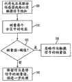
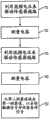
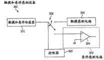
图35示出了根据各实施例的可以在触摸和悬停模式之间切换的示例性触摸和悬停感测设备。在图35的示例中,触摸和悬停感测设备3500可以具有由传感器线路构成的并耦合到触摸和悬停控制系统3507的传感器3512,触摸和悬停控制系统3507可以控制在触摸模式和悬停模式之间的传感器切换。控制系统3507可包括开关3539、触摸感测电路3516、悬停感测电路3518以及控制器3520。开关3539可以将传感器3512耦合到感测电路3516、3518中任何一个。在触摸模式下,开关3539可以将传感器3512耦合到触摸感测电路3516以处理触摸信号。在悬停模式下,开关3539可以将传感器3512耦合到悬停感测电路3518以处理悬停信号。控制器3520可以根据任何合适的控制方案来控制开关3539。在某些实施例中,控制器3520可以响应于计时器,在两种模式之间切换,其中当计时器到期时进行切换。此时,计时器可以被复位,以倒计数到下一次切换。在某些实施例中,控制器3520可以响应于诸如来自用户的手动输入或当发生特定条件时来自设备的逻辑输入之类的输入,在两种模式之间切换。FIG. 35 illustrates an example touch and hover sensing device that can switch between touch and hover modes in accordance with various embodiments. In the example of FIG. 35 , a touch and hover
开关3539可以具有会干扰来自传感器3512的触摸信号或悬停信号的大量的电容。干扰会在其中悬停感测电路可以测量绝对电容的悬停信号中更不利。相比之下,干扰会在其中触摸感测电路可以测量微变电容(或电容变化)的触摸信号中不太不利,而在某些情况下,是有利的。例如,在某些实施例中,开关电容可以大约是20pF,这可以是信号的动态范围。开关电容可以随着设备组件一起偏移,如下面的图36和37所示。
图36示出了可以在触摸模式和悬停模式之间切换的另一示例性触摸和悬停感测设备,该设备具有用于偏移会被用来在两种模式之间改变的开关引入到设备中的电容的增益放大器。在图36的示例中,悬停感测电路3618的增益放大器3644可以在一个针脚上接收到指示传感器3612上的悬停以及开关3639中的电容的悬停感测信号,并可以在另一个针脚接收到放大器可以从悬停感测信号中减去的参考信号。从增益放大器3644所产生的输出可以是在传感器3612测量到的悬停的不饱和的、校正的悬停信号。Figure 36 shows another exemplary touch and hover sensing device that can switch between touch mode and hover mode, the device has a switch introduction for offset that would be used to change between the two modes to the gain amplifier of the capacitance in the device. In the example of FIG. 36 ,
图37示出了可以在触摸模式和悬停模式之间切换的另一示例性触摸和悬停感测设备,该设备具有用于偏移会被用来在两种模式之间改变的开关引入到设备中的电容的电容器。在图37的示例中,电容器3756可以位于传感器3712和开关3739之间。电容器的电容可以与开关电容串联,从而有效地将由悬停感测电路3718遇到的总电容减小一半。所产生的到悬停感测电路3718的信号可以不饱和,敏感性降低。37 shows another exemplary touch and hover sensing device that can switch between touch mode and hover mode, the device has a switch introduction for offset that will be used to change between the two modes. capacitor to the capacitance in the device. In the example of FIG. 37 ,
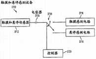
作为用于在触摸模式和悬停模式之间切换的开关的替代方案,可以使用逻辑来在各模式之间切换。图38示出了根据各实施例的在触摸模式和悬停模式之间切换的示例性触摸和悬停感测设备。在图38的示例中,触摸和悬停感测设备3800可以具有由传感器线路构成的并耦合到触摸和悬停控制系统3807的传感器3812,触摸和悬停控制系统3807可以控制在触摸模式和悬停模式之间的传感器切换。控制系统3807可包括触摸感测电路3816、悬停感测电路3818、以及控制器3820。悬停感测电路3818和触摸感测电路3816可以在耦合到传感器3812的线路上连接到一起。控制器3820可以根据模式来禁用和启用感测电路3816、3818。在触摸模式下,控制器3820可以向触摸感测电路3816发送启用信号,向悬停感测电路3818发送禁用信号,以便触摸感测电路可以处理传感器信号,悬停感测电路可以浮动。在悬停模式下,控制器3820可以向触摸感测电路3816发送禁用信号,向悬停感测电路3818发送启用信号,以便悬停感测电路可以处理传感器信号,触摸感测电路可以浮动。控制器3820可以根据任何合适的控制方案来生成和发送禁用信号和启用信号。在某些实施例中,控制器3820可以在计时器到期之后生成和发送禁用信号和启用信号。控制器3820可以在发送信号之后复位计时器。在某些实施例中,控制器3820可以响应于设备上的特定条件,例如根据对象与传感器3812的接近度,来生成和发送禁用信号和启用信号。As an alternative to a switch for switching between touch mode and hover mode, logic can be used to switch between the modes. FIG. 38 illustrates an example touch and hover sensing device that switches between touch mode and hover mode, in accordance with various embodiments. In the example of FIG. 38 , a touch and hover sensing device 3800 may have a
在将触摸感测电路3816和悬停感测电路3818连接在一起的线路上会有寄生电容,寄生电容会干扰来自传感器3812的触摸信号和悬停信号。如上所述,干扰在悬停信号中比在触摸信号中更不利。在一个实施例中,为降低寄生电容对悬停信号的影响,可以调整触摸感测电路和悬停感测电路的特征,以便通过触摸感测电路上的电阻器来提供高阻态,以迫使来自传感器的电压路径停留在悬停感测电路中,并阻止触摸感测电路中的寄生电容干涉。还有其他解决方案可用于减小寄生电容。There will be parasitic capacitance on the line connecting the
图39示出了根据各实施例的基于对象与设备的接近度来在触摸和悬停感测设备的触摸模式和悬停模式之间切换的示例性方法。此方法可以根据设备的需求,以软件、固件、或硬件来实现,以基于模式使开关将传感器耦合到适当的感测电路,如在图35到37中那样,或基于模式启用或者禁用感测电路,如在图38中那样。在图39的示例中,触摸感测设备的控制器可以切换到悬停模式,以便设备的悬停感测电路可以测量设备的传感器处的悬停电容(3910)。在某些实施例中,控制器可以发送控制信号以驱动开关与悬停感测电路耦合。在某些实施例中,控制器可以向悬停感测电路发送启用信号,并向触摸感测电路发送禁用信号。39 illustrates an example method of switching between touch and hover modes of a touch and hover sensing device based on the proximity of an object to the device, in accordance with various embodiments. This method can be implemented in software, firmware, or hardware, depending on the needs of the device, to have a switch couple the sensor to the appropriate sensing circuit based on the mode, as in Figures 35 to 37, or to enable or disable sensing based on the mode circuit, as in Figure 38. In the example of FIG. 39, the controller of the touch-sensing device may switch to hover mode so that the device's hover-sensing circuitry may measure the hover capacitance at the device's sensor (3910). In some embodiments, the controller may send a control signal to actuate a switch coupled to the hover sensing circuit. In some embodiments, the controller may send an enable signal to the hover sensing circuit and a disable signal to the touch sensing circuit.
可以基于悬停测量值,就对象是否远离设备作出判断(3920)。为执行判断,可以将悬停测量值与阈值悬停测量值进行比较。如果悬停测量值等于或低于悬停阈值,则可以判断对象在远处。如果悬停测量值高于悬停阈值,则可以判断对象在近处。A determination may be made as to whether the object is far from the device based on the hover measurements (3920). To perform the determination, the hover measurement may be compared to a threshold hover measurement. An object can be judged to be far away if the hover measurement is at or below the hover threshold. An object can be judged to be nearby if the hover measurement is above the hover threshold.
如果判断对象在远处,则设备可以继续处于悬停模式下,重复悬停电容测量(3910),并判断对象是否仍在远处(3920),直到悬停测量值超过悬停阈值,指示对象正在触摸或几乎触摸设备。If it is determined that the object is far away, the device may continue to be in hover mode, repeat the hover capacitance measurement (3910), and determine whether the object is still far away (3920), until the hover measurement value exceeds the hover threshold, indicating the object Touching or nearly touching the device.
然而,如果判断对象在近处,控制器可以切换到触摸模式,以便设备的触摸感测电路可以测量传感器处的触摸电容(3930)。在某些实施例中,控制器可以发送控制信号以驱动开关与触摸感测电路耦合。在某些实施例中,控制器可以向触摸感测电路发送启用信号,并向悬停感测电路发送禁用信号。However, if the object is determined to be nearby, the controller may switch to touch mode so that the device's touch sensing circuitry may measure the touch capacitance at the sensor (3930). In some embodiments, the controller may send a control signal to drive a switch coupled with the touch sensing circuit. In some embodiments, the controller may send an enable signal to the touch sensing circuit and a disable signal to the hover sensing circuit.
可以基于触摸测量值,就对象是否触摸设备作出判断(3940)。为执行判断,可以将触摸测量值与阈值触摸测量值进行比较。如果触摸测量值等于或高于触摸阈值,则可以判断对象正在触摸设备。如果触摸测量值低于触摸阈值,则可以判断对象不正在触摸设备。Based on the touch measurements, a determination may be made as to whether the object is touching the device (3940). To perform the determination, the touch measurement may be compared to a threshold touch measurement. If the touch measurement is equal to or higher than the touch threshold, it can be determined that the object is touching the device. If the touch measurement is below the touch threshold, it may be determined that the object is not touching the device.
如果判断对象正在触摸设备,则该设备可以在触摸模式下继续,重复触摸电容测量(3930),并判断对象是否仍触摸设备(3940),直到触摸测量值低于触摸阈值,指示不再有对设备的触摸。If it is determined that the object is touching the device, the device may continue in touch mode, repeating the touch capacitance measurement (3930), and determining whether the object is still touching the device (3940), until the touch measurement is below the touch threshold, indicating that there is no more contact device touch.
然而,如果判断对象不正在触摸设备,则测量可以被视为模糊,因为它在阈值悬停测量值和阈值触摸测量值之间。如此,设备可以在两种模式之间切换,直到测量值满足阈值中的任何一个。相应地,控制器可以切换回悬停模式,方法可以重复(3910)到(3940)。However, if it is determined that the object is not touching the device, the measurement may be considered ambiguous because it is between the threshold hover measurement and the threshold touch measurement. In this way, the device can switch between the two modes until the measured value satisfies either of the thresholds. Accordingly, the controller may switch back to hover mode and the method may repeat ( 3910 ) to ( 3940 ).
可以理解,图39的方法不仅限于所示出的那些,而且还可根据设备的需求包括额外的和/或其他动作。It will be appreciated that the method of FIG. 39 is not limited to those shown, but may include additional and/or other actions as required by the device.
图40示出了根据各实施例的基于计时器来在触摸和悬停感测设备的触摸模式和悬停模式之间切换的另一示例性方法。此方法可以根据设备的需求,以软件、固件、或硬件来实现,以基于模式使开关将传感器耦合到适当的感测电路,如在图35到37中那样,或基于模式启用或者禁用感测电路,如在图38中那样。在图40的示例中,触摸和悬停感测设备的控制器可以判断计时器是否已经到期(4010)。如果计时器没有到期,则设备可以继续处于当前模式(4020)。如果处于触摸模式下,则设备的传感器可以耦合到触摸感测电路。如果处于悬停模式下,则传感器可以耦合到悬停感测电路。40 illustrates another exemplary method of switching between touch and hover modes of a touch and hover sensing device based on a timer, in accordance with various embodiments. This method can be implemented in software, firmware, or hardware, depending on the needs of the device, to have a switch couple the sensor to the appropriate sensing circuit based on the mode, as in Figures 35 to 37, or to enable or disable sensing based on the mode circuit, as in Figure 38. In the example of FIG. 40, the controller of the touch and hover sensing device may determine whether a timer has expired (4010). If the timer has not expired, the device may continue in the current mode (4020). If in touch mode, the device's sensors may be coupled to touch sensing circuitry. If in hover mode, the sensor may be coupled to the hover sensing circuit.
如果计时器已经到期,则控制器可以复位计时器(4030)。控制器可以切换到另一模式(4040)。如果设备处于触摸模式,则设备可以切换到悬停模式。在某些实施例中,为执行切换,控制器可以发送控制信号以驱动开关从触摸感测电路脱离并耦合到悬停感测电路。在其他实施例中,为执行切换,控制器可以向悬停感测电路发送启用信号,并向触摸感测电路发送禁用信号。然而,如果设备处于悬停模式,则设备可以切换到触摸模式。在某些实施例中,为执行切换,控制器可以发送控制信号以驱动开关从悬停感测电路脱离并耦合到触摸感测电路。在其他实施例中,为执行切换,控制器可以向触摸感测电路发送启用信号,并向悬停感测电路发送禁用信号。If the timer has expired, the controller may reset the timer (4030). The controller may switch to another mode (4040). If the device is in touch mode, the device can switch to hover mode. In some embodiments, to perform the switching, the controller may send a control signal to drive the switch decoupled from the touch sensing circuit and coupled to the hover sensing circuit. In other embodiments, to perform the switching, the controller may send an enable signal to the hover sensing circuit and a disable signal to the touch sensing circuit. However, if the device is in hover mode, the device can switch to touch mode. In some embodiments, to perform the switching, the controller may send a control signal to drive the switch out of the hover sensing circuit and coupled to the touch sensing circuit. In other embodiments, to perform the switching, the controller may send an enable signal to the touch sensing circuit and a disable signal to the hover sensing circuit.
在切换到另一模式之后,控制器可以重复方法(4010)到(4040),检查计时器的到期,在到期之后,复位计时器并切换到不同的模式。After switching to another mode, the controller may repeat methods (4010) to (4040), checking for expiration of the timer, after which, resetting the timer and switching to a different mode.
可以理解,图40的方法不仅限于所示出的那些,而且还可根据设备的需求包括额外的和/或其他动作。It will be appreciated that the method of FIG. 40 is not limited to those shown, but may include additional and/or other actions as required by the device.
在触摸和悬停切换中,传感器的某些或全部可以在两种模式之间切换。例如,在某些实施例中,传感器的一部分可以被切换到悬停模式以耦合到悬停感测电路,传感器的一部分可以被切换到触摸模式以耦合到触摸感测电路。这可以实现面板分区,如上所述。在其他实施例中,全部传感器可以被切换到悬停模式以耦合到悬停感测电路,或耦合到触摸模式以耦合到触摸感测电路。In touch and hover switching, some or all of the sensors can be switched between the two modes. For example, in some embodiments, a portion of the sensor may be switched to hover mode for coupling to the hover sensing circuit and a portion of the sensor may be switched to touch mode for coupling to the touch sensing circuit. This enables panel partitioning, as described above. In other embodiments, all sensors may be switched to hover mode for coupling to hover sensing circuitry, or to touch mode for coupling to touch sensing circuitry.
显示器集成Display integration
在某些实施例中,触摸和悬停感测设备可以将显示设备与触摸和悬停感测面板集成,其中,显示器可以通过来自面板的触摸或悬停信号来提供带有可选择的各种图形的图形用户界面,以使设备执行与所选图形相关联的动作。由于其与面板的接近,显示器会干扰由面板所生成的触摸或悬停信号,从而产生噪声,降低触摸或悬停灵敏度,或以其他方式对信号产生不利的影响。这会导致非故意的设备动作。In some embodiments, the touch and hover sensing device can integrate a display device with a touch and hover sensing panel, wherein the display can provide various Graphical user interface of the graphic to cause the device to perform the action associated with the selected graphic. Due to its proximity to the panel, the display can interfere with touch or hover signals generated by the panel, thereby generating noise, reducing touch or hover sensitivity, or otherwise adversely affecting the signal. This can result in unintentional device actions.
图41示出了根据各实施例的可以减少设备显示器与设备触摸和悬停感测面板之间的干扰的示例性触摸和悬停感测设备。在图41的示例中,可以在触摸和悬停感测面板4126与显示器4128之间安置接地屏蔽4138。接地屏蔽4138可以帮助将面板4126与显示器4128电隔离,以降低显示器对面板的不希望的影响。41 illustrates an example touch and hover sensing device that can reduce interference between a device display and a device touch and hover sensing panel, in accordance with various embodiments. In the example of FIG. 41 , a
图42示出了根据各实施例的可以减少设备显示器与设备触摸和悬停感测面板之间的干扰的另一示例性触摸和悬停感测设备。在图42的示例中,触摸和悬停感测面板4226与显示器4228可以相隔最佳距离d。最佳距离可以是从显示器对面板的影响被大大地减小或消除以便触摸和悬停信号被最低限度地影响的距离。在某些实施例中,最佳距离d=1mm。这里,最佳距离d可以大大地减小或消除对接地屏蔽的需求。42 illustrates another exemplary touch and hover sensing device that can reduce interference between a device display and a device touch and hover sensing panel, in accordance with various embodiments. In the example of FIG. 42, the touch and hover
示例性触摸和悬停感测设备Exemplary touch and hover sensing device
图43示出了根据此处所描述的各实施例的可以具有触摸和悬停感测的示例性计算系统4300。在图43的示例中,计算系统4300可包括触摸和悬停控制系统4306。触摸和悬停控制系统4306可以是可包括一个或多个处理器子系统4302(可包括诸如ARM968处理器之类的一个或多个主处理器,或带有类似的功能和能力的其他处理器)的单个专用集成电路(ASIC)。然而,在其他实施例中,处理器功能可以由诸如状态机之类的专用逻辑来实现。处理器子系统4302还可以包括诸如随机存取存储器(RAM)或其他类型的存储器或存储装置、看守计时器等等之类的外围设备(未示出)。触摸和悬停控制系统4306还可以包括用于接收诸如一个或多个感测通道(未示出)的触摸和悬停信号4303的信号,来自诸如传感器4311等等之类的其他传感器的其他信号的接收部分4307。接收部分4307可包括触摸感测电路、悬停感测电路、以及根据接收到的触摸和悬停信号4303来在感测电路之间切换的切换机构。触摸和悬停控制系统4306还可以包括诸如多级矢量解调引擎之类的解调部分4309、面板扫描逻辑4310、以及用于将激励信号4316传输到触摸和悬停传感器面板4324以驱动面板的传输部分4314。面板扫描逻辑4310可以访问RAM4312,从感测通道自主地读取数据,并为感测通道提供控制。另外,面板扫描逻辑4310还可以控制传输部分4314,以便以各种频率和相位生成可以有选择地向传感器面板4324的水平线路和/或垂直线路施加的激励信号4316。FIG. 43 illustrates an
触摸和悬停控制系统4306还可以包括可以被用来为传输部分4314生成电源电压的电荷泵4315。激励信号4316可以通过将两个电荷存储设备,例如电容器,级联在一起以构成电荷泵4315,具有高于最大电压的振幅。因此,激励电压可以比单个电容器可以处理的电压电平(例如,3.6V)更高(例如,43V)。虽然图43示出了电荷泵4315是与传输部分4314分开的,但是电荷泵可以是传输部分的一部分。The touch and hover
触摸和悬停传感器面板4324可包括具有用于检测面板上触摸事件或悬停事件的传感器的电容性感测介质。传感器可以由诸如氧化锡铟(ITO)或氧化锡锑(ATO)之类的透明导电介质构成,虽然还可以使用诸如铜之类的其他透明和不透明材料。每个传感器都可以代表电容性感测节点,并可以被视为图像元素(像素)4326,该图像元素4326在传感器面板4324被视为捕捉触摸或悬停的“图像”时可以特别有用。(换言之,在触摸和悬停控制系统4306确定是否在传感器面板中的每个传感器中检测到触摸事件或悬停事件之后,面板中发生了触摸事件或悬停事件的传感器模式可以视为触摸或悬停的“图像”(例如,对象触摸或在面板上方悬停的模式)。)Touch and hover
计算系统4300还可以包括用于接收来自处理器子系统4302的输出并基于输出执行可包括但不仅限于下列各项的动作的主机处理器4328,移动诸如光标或指针之类的对象,滚动或摇摄,调整控制设置,打开文件或文档,查看菜单,进行选择,执行指令,操作耦合到主机设备的外围设备,应答电话呼叫,拨打电话,结束电话呼叫,改变音量或音频设置,存储涉及电话通信的诸如地址、频繁拨打的号码、已接来电、未接来电的信息,登录到计算机或计算机网络,准许授权的个人访问计算机或计算机网络的受限制区域,加载与用户的计算机桌面的首选布局相关联的用户简档,准许访问Web内容,启动特定程序,加密或解码消息,和/或等等。主机处理器4328还可以执行可能不涉及面板处理的额外功能,并可以耦合到程序存储器4332和用于向设备的用户提供UI的诸如LCD显示器之类的显示设备4330。在某些实施例中,主机处理器4328可以是与触摸和悬停控制系统4306分开的组件,如图所示。在其他实施例中,主机处理器4328可以作为触摸和悬停控制系统4306的一部分被包括。在其他实施例中,主机处理器4328的功能可以由处理器子系统4302执行和/或在触摸和悬停控制系统4306的其他组件之间分配。显示设备4330与触摸和悬停传感器面板4324一起,当部分地或完全定位在传感器面板下面时或当与传感器面板集成时,可以构成诸如触摸屏之类的触敏设备。
请注意,上文所描述的功能中的一个或多个,可以例如通过存储在存储器(例如,外围设备中的一个)中的并由处理器子系统4302执行的,或存储在程序存储器4332中的并由主机处理器4328执行的固件来执行。固件还可以被存储在任何计算机可读存储介质内和/或在任何计算机可读存储介质内传输,供诸如基于计算机的系统,包含处理器的系统之类的指令执行系统、设备或装置,或从指令执行系统、设备或装置获取指令并执行指令的其他系统使用或与它们一起使用。在此文档的上下文中,“计算机可读存储介质”可以是可以包含或存储供指令执行系统、设备或装置使用或与它们一起使用的程序的任何介质。计算机可读存储介质可包括但不仅限于电子、磁性、光学、电磁、红外线、或半导体系统、设备,便携式计算机磁盘(磁性)、随机存取存储器(RAM)(磁性)、只读存储器(ROM)(磁性)、只读存储器(ROM)(磁性)、可擦写可编程只读存储器(EPROM)(磁性)、便携式光盘诸如CD、CD-R、CD-RW、DVD、DVD-R、或DVD-RW,或闪存诸如紧凑型闪存卡、安全数字卡、USB存储器设备、记忆棒等等。Note that one or more of the functions described above may be performed by
固件还可以在任何传输介质内传播,供诸如基于计算机的系统,包含处理器的系统之类的指令执行系统、设备或装置,或从指令执行系统、设备或装置获取指令并执行指令的其他系统使用或与它们一起使用。在此文档的上下文中,“传输介质”可以是可以传递、传播或传输供指令执行系统、设备或装置使用或与它们一起使用的程序的任何介质。传输介质可包括但不仅限于电子、磁性、光学、电磁或红外线有线或无线传播介质。Firmware may also be transmitted over any transmission medium for an instruction execution system, device or device such as a computer-based system, a system containing a processor, or other system that receives instructions from an instruction execution system, device or device and executes the instructions use or with them. In the context of this document, a "transmission medium" may be any medium that can convey, propagate, or transport the program for use by or with an instruction execution system, apparatus, or device. Transmission media may include, but is not limited to, electronic, magnetic, optical, electromagnetic, or infrared wired or wireless propagation media.
图44示出了根据各实施例的可包括显示器4436与触摸和悬停传感器面板4424的示例性移动电话4400。FIG. 44 illustrates an exemplary
图45示出了根据各实施例的可包括显示器4536与触摸和悬停传感器面板4524的示例性数字媒体播放器4500。FIG. 45 illustrates an exemplary
图46示出了根据各实施例的可包括触摸和悬停敏感显示器4636与触摸和悬停传感器面板(跟踪板)4624的示例性个人计算机4600。Figure 46 illustrates an exemplary
图44到46的移动电话、媒体播放器、以及个人计算机可以有利地提供根据各实施例的改善的触摸和悬停感测。The mobile phones, media players, and personal computers of Figures 44-46 may advantageously provide improved touch and hover sensing in accordance with various embodiments.
在上面的示例中,电容测量值可以是在特定时间电容的度量,即绝对电容,或在特定时间段内电容差异的度量,即电容变化。相应地,在某些实施例中,触摸事件或悬停事件可以通过对触摸和悬停感测设备的感测线路处的绝对电容的测量来检测。在其他实施例中,触摸事件或悬停事件可以通过对触摸和悬停感测设备的感测线路处的电容变化的测量来检测。在其他实施例中,触摸事件或悬停事件可以通过对触摸和悬停感测设备的感测线路处的绝对电容的测量值与电容变化的组合来检测。特定测量值可以根据由设备执行的特定功能,例如信号补偿、信号检测等等来确定。In the example above, the capacitance measurement could be a measure of capacitance at a particular time, ie absolute capacitance, or a measure of the difference in capacitance over a particular time period, ie capacitance change. Accordingly, in some embodiments, touch events or hover events may be detected by measuring the absolute capacitance at the sense lines of the touch and hover sensing device. In other embodiments, touch events or hover events may be detected by measurement of capacitance changes at the sense lines of the touch and hover sensing device. In other embodiments, touch events or hover events may be detected by a combination of measurements of absolute capacitance and changes in capacitance at the sense lines of the touch and hover sensing device. Specific measurements may be determined according to specific functions performed by the device, such as signal compensation, signal detection, and the like.
虽然是参考附图来描述各实施例的,但是值得注意的是,对那些精通本技术的人显而易见的是,可以有各种更改和修改方案。这样的更改和修改方案被理解为包括在如所附权利要求书所定义的各实施例的范围内。Although the embodiments have been described with reference to the accompanying drawings, it is to be noted that various changes and modifications will be apparent to those skilled in the art. Such changes and modifications are understood to be included within the scope of the various embodiments as defined by the appended claims.
Claims (25)
Translated fromChinesePriority Applications (1)
| Application Number | Priority Date | Filing Date | Title |
|---|---|---|---|
| CN201610846833.9ACN106354331B (en) | 2010-08-27 | 2011-08-05 | It touches and hovering switches |
Applications Claiming Priority (5)
| Application Number | Priority Date | Filing Date | Title |
|---|---|---|---|
| US37782910P | 2010-08-27 | 2010-08-27 | |
| US61/377,829 | 2010-08-27 | ||
| US12/895,643 | 2010-09-30 | ||
| US12/895,643US9268431B2 (en) | 2010-08-27 | 2010-09-30 | Touch and hover switching |
| PCT/US2011/046814WO2012027086A2 (en) | 2010-08-27 | 2011-08-05 | Touch and hover switching |
Related Child Applications (1)
| Application Number | Title | Priority Date | Filing Date |
|---|---|---|---|
| CN201610846833.9ADivisionCN106354331B (en) | 2010-08-27 | 2011-08-05 | It touches and hovering switches |
Publications (2)
| Publication Number | Publication Date |
|---|---|
| CN103168284Atrue CN103168284A (en) | 2013-06-19 |
| CN103168284B CN103168284B (en) | 2016-08-31 |
Family
ID=44543815
Family Applications (3)
| Application Number | Title | Priority Date | Filing Date |
|---|---|---|---|
| CN201180049070.0AExpired - Fee RelatedCN103168284B (en) | 2010-08-27 | 2011-08-05 | Touch and hover toggle |
| CN201610846833.9AExpired - Fee RelatedCN106354331B (en) | 2010-08-27 | 2011-08-05 | It touches and hovering switches |
| CN201180049079.1AExpired - Fee RelatedCN103154866B (en) | 2010-08-27 | 2011-08-05 | For the parallel signal process touching and hovering senses |
Family Applications After (2)
| Application Number | Title | Priority Date | Filing Date |
|---|---|---|---|
| CN201610846833.9AExpired - Fee RelatedCN106354331B (en) | 2010-08-27 | 2011-08-05 | It touches and hovering switches |
| CN201180049079.1AExpired - Fee RelatedCN103154866B (en) | 2010-08-27 | 2011-08-05 | For the parallel signal process touching and hovering senses |
Country Status (5)
| Country | Link |
|---|---|
| US (8) | US9851829B2 (en) |
| EP (2) | EP2609492A2 (en) |
| KR (2) | KR101528687B1 (en) |
| CN (3) | CN103168284B (en) |
| WO (3) | WO2012027087A2 (en) |
Cited By (20)
| Publication number | Priority date | Publication date | Assignee | Title |
|---|---|---|---|---|
| CN104102403A (en)* | 2014-07-11 | 2014-10-15 | 北京智谷睿拓技术服务有限公司 | Distribution determining method and device |
| CN104423756A (en)* | 2013-09-09 | 2015-03-18 | 太瀚科技股份有限公司 | Touch panel control method |
| CN104423881A (en)* | 2013-08-26 | 2015-03-18 | 佳能株式会社 | Information processing device and method for controlling the same |
| CN105807977A (en)* | 2014-12-31 | 2016-07-27 | 清华大学 | Touch and suspension sensing device |
| TWI566136B (en)* | 2014-12-31 | 2017-01-11 | 鴻海精密工業股份有限公司 | Touch and hover sensing device |
| CN106354331A (en)* | 2010-08-27 | 2017-01-25 | 苹果公司 | Touch and hover switching |
| TWI585439B (en)* | 2014-12-31 | 2017-06-01 | 鴻海精密工業股份有限公司 | Electrostatic sensing device |
| TWI585438B (en)* | 2014-12-31 | 2017-06-01 | 鴻海精密工業股份有限公司 | Electrostatic sensing device |
| TWI585440B (en)* | 2014-12-31 | 2017-06-01 | 鴻海精密工業股份有限公司 | Electrostatic sensing device |
| TWI585441B (en)* | 2014-12-31 | 2017-06-01 | 鴻海精密工業股份有限公司 | Electrostatic sensing device |
| TWI593991B (en)* | 2014-12-31 | 2017-08-01 | 鴻海精密工業股份有限公司 | Electrostatic sensing method |
| US10101374B2 (en) | 2014-12-31 | 2018-10-16 | Tsinghua University | Electrostatic distribution measuring instrument |
| US10145879B2 (en) | 2014-12-31 | 2018-12-04 | Tsinghua University | Electrometer |
| US10209285B2 (en) | 2014-12-31 | 2019-02-19 | Tsinghua University | Electrometer |
| CN109416609A (en)* | 2016-10-27 | 2019-03-01 | 瑟克公司 | With the finger trail in the input unit close to sensing |
| CN109828693A (en)* | 2013-08-13 | 2019-05-31 | 三星电子株式会社 | Interaction sensor device and interaction method for sensing |
| US10310660B2 (en) | 2014-12-31 | 2019-06-04 | Tsinghua University | Hover controlling device |
| US10310661B2 (en) | 2014-12-31 | 2019-06-04 | Tsinghua University | Hover controlling device |
| CN110069165A (en)* | 2019-04-29 | 2019-07-30 | 广州视源电子科技股份有限公司 | Touch data processing method, device, equipment and storage medium |
| US10417996B2 (en) | 2017-08-31 | 2019-09-17 | Yuan Ze University | Method, image processing device, and display system for power-constrained image enhancement |
Families Citing this family (264)
| Publication number | Priority date | Publication date | Assignee | Title |
|---|---|---|---|---|
| US9740341B1 (en) | 2009-02-26 | 2017-08-22 | Amazon Technologies, Inc. | Capacitive sensing with interpolating force-sensitive resistor array |
| US10180746B1 (en) | 2009-02-26 | 2019-01-15 | Amazon Technologies, Inc. | Hardware enabled interpolating sensor and display |
| US8355887B1 (en) | 2009-04-24 | 2013-01-15 | Cypress Semiconductor Corporation | Proximity based gesturing devices, systems and methods |
| US9737796B2 (en) | 2009-07-08 | 2017-08-22 | Steelseries Aps | Apparatus and method for managing operations of accessories in multi-dimensions |
| US8719714B2 (en) | 2009-07-08 | 2014-05-06 | Steelseries Aps | Apparatus and method for managing operations of accessories |
| US9323398B2 (en) | 2009-07-10 | 2016-04-26 | Apple Inc. | Touch and hover sensing |
| US8723827B2 (en) | 2009-07-28 | 2014-05-13 | Cypress Semiconductor Corporation | Predictive touch surface scanning |
| US9785272B1 (en) | 2009-07-31 | 2017-10-10 | Amazon Technologies, Inc. | Touch distinction |
| US9740340B1 (en) | 2009-07-31 | 2017-08-22 | Amazon Technologies, Inc. | Visually consistent arrays including conductive mesh |
| US8638107B2 (en)* | 2009-12-18 | 2014-01-28 | Synaptics Incorporated | Transcapacitive sensor devices with ohmic seams |
| KR20110103140A (en)* | 2010-03-12 | 2011-09-20 | 삼성전자주식회사 | Multi-touch and proximity object sensing device for selectively irradiating light |
| US9766733B2 (en)* | 2010-04-16 | 2017-09-19 | Microchip Technology Germany Gmbh | TFT display, OLED interface and method for detecting the spatial position of extremities in a spatial region located in front of the display |
| KR101710657B1 (en)* | 2010-08-05 | 2017-02-28 | 삼성디스플레이 주식회사 | Display device and driving method thereof |
| CN102576276B (en)* | 2010-08-23 | 2017-05-10 | 谱瑞科技股份有限公司 | Capacitive Scan Proximity Detection |
| US20120120002A1 (en)* | 2010-11-17 | 2012-05-17 | Sony Corporation | System and method for display proximity based control of a touch screen user interface |
| FR2968488B1 (en) | 2010-12-01 | 2012-12-21 | St Microelectronics Rousset | METHOD FOR CONTROLLING A CAPACITIVE TOUCH SURFACE |
| FR2968487B1 (en) | 2010-12-01 | 2012-12-21 | St Microelectronics Rousset | DIRECTIONAL DETECTION DEVICE FOR CAPACITIVE PROXIMITY |
| FR2968421B1 (en) | 2010-12-01 | 2013-04-05 | St Microelectronics Rousset | CAPACITIVE TOUCH SURFACE CONFIGURED TO MAKE PROXIMITY DETECTION |
| KR101694272B1 (en)* | 2010-12-03 | 2017-01-10 | 삼성전자주식회사 | Apparatus and method for detecting touch and proximity information in display apparatus |
| KR20120084860A (en)* | 2011-01-21 | 2012-07-31 | 삼성전자주식회사 | Method for inputting in capacity touch screen terminal and device thereof |
| US9417696B2 (en)* | 2011-01-27 | 2016-08-16 | Blackberry Limited | Portable electronic device and method therefor |
| US9952737B2 (en) | 2011-02-24 | 2018-04-24 | Parade Technologies, Ltd. | Single layer touch sensor |
| US9389258B2 (en) | 2011-02-24 | 2016-07-12 | Parade Technologies, Ltd. | SLIM sensor design with minimum tail effect |
| US8866490B1 (en)* | 2013-01-18 | 2014-10-21 | Cypress Semiconductor Corporation | Method and apparatus for eliminating tail effect in touch applications |
| US8866491B2 (en) | 2011-02-24 | 2014-10-21 | Cypress Semiconductor Corporation | Tail effect correction for SLIM pattern touch panels |
| CN102722297B (en)* | 2011-03-30 | 2016-01-13 | 中兴通讯股份有限公司 | A kind of touch panel device and the method realized close to induction thereof |
| US9285950B2 (en)* | 2011-03-30 | 2016-03-15 | Google Inc. | Hover-over gesturing on mobile devices |
| TWI457796B (en)* | 2011-03-31 | 2014-10-21 | Novatek Microelectronics Corp | Driving method for touch-sensing display device and touch-sensing device thereof |
| DE102011017383A1 (en)* | 2011-04-18 | 2012-10-18 | Ident Technology Ag | OLED interface |
| JP5220886B2 (en)* | 2011-05-13 | 2013-06-26 | シャープ株式会社 | Touch panel device, display device, touch panel device calibration method, program, and recording medium |
| US9104272B2 (en)* | 2011-05-23 | 2015-08-11 | Sony Corporation | Finger-on display detection |
| JP2012247936A (en)* | 2011-05-26 | 2012-12-13 | Sony Corp | Information processor, display control method and program |
| US8427452B2 (en)* | 2011-05-31 | 2013-04-23 | Pixart Imaging, Inc. | Charge pump frequency selection in touch screen sensor interface system |
| TWI447066B (en)* | 2011-06-08 | 2014-08-01 | Sitronix Technology Corp | Distance sensing circuit and touch electronic device |
| US20130050131A1 (en)* | 2011-08-23 | 2013-02-28 | Garmin Switzerland Gmbh | Hover based navigation user interface control |
| CN102999198B (en)* | 2011-09-16 | 2016-03-30 | 宸鸿科技(厦门)有限公司 | Touch panel edge holds detection method and the device of touch |
| US20130083074A1 (en)* | 2011-10-03 | 2013-04-04 | Nokia Corporation | Methods, apparatuses and computer program products utilizing hovering, in part, to determine user interface orientation |
| US20130088434A1 (en)* | 2011-10-06 | 2013-04-11 | Sony Ericsson Mobile Communications Ab | Accessory to improve user experience with an electronic display |
| US9658715B2 (en) | 2011-10-20 | 2017-05-23 | Microsoft Technology Licensing, Llc | Display mapping modes for multi-pointer indirect input devices |
| US9274642B2 (en) | 2011-10-20 | 2016-03-01 | Microsoft Technology Licensing, Llc | Acceleration-based interaction for multi-pointer indirect input devices |
| US8933896B2 (en)* | 2011-10-25 | 2015-01-13 | Microsoft Corporation | Pressure-based interaction for indirect touch input devices |
| EP2587348B1 (en)* | 2011-10-28 | 2020-12-02 | Nintendo Co., Ltd. | Information processing program, information processing system, and information processing method |
| JP5827870B2 (en) | 2011-10-28 | 2015-12-02 | 任天堂株式会社 | Coordinate processing program, coordinate processing apparatus, coordinate processing system, and coordinate processing method |
| US8760423B2 (en) | 2011-10-28 | 2014-06-24 | Nintendo Co., Ltd. | Computer-readable storage medium, information processing apparatus, information processing system, and information processing method |
| US8773382B2 (en) | 2011-10-28 | 2014-07-08 | Nintendo Co., Ltd. | Computer-readable storage medium, coordinate processing apparatus, coordinate processing system, and coordinate processing method |
| DE102011086144A1 (en)* | 2011-11-11 | 2013-05-16 | Robert Bosch Gmbh | Method for correcting measured values of a sensor element |
| US9389679B2 (en) | 2011-11-30 | 2016-07-12 | Microsoft Technology Licensing, Llc | Application programming interface for a multi-pointer indirect touch input device |
| DE112011105894T5 (en)* | 2011-11-30 | 2014-11-06 | Hewlett-Packard Development Company, L.P. | Input method based on a location of a hand gesture |
| CN108459757B (en)* | 2011-12-19 | 2022-04-01 | 禾瑞亚科技股份有限公司 | Processor and touch control method of touch screen |
| US9116598B1 (en)* | 2012-01-10 | 2015-08-25 | Koji Yoden | User interface for use in computing device with sensitive display |
| US20130194314A1 (en)* | 2012-01-26 | 2013-08-01 | Nokia Corporation | Desktop extension |
| US8937602B2 (en) | 2012-02-01 | 2015-01-20 | Logitech Europe S.A. | System and method for rocking finger and static finger detection on an input device |
| US8970519B2 (en) | 2012-02-01 | 2015-03-03 | Logitech Europe S.A. | System and method for spurious signal detection and compensation on an input device |
| US20130194235A1 (en)* | 2012-02-01 | 2013-08-01 | Logitec Europe S.A. | Multi-sensor input device |
| US20140208957A1 (en)* | 2012-02-14 | 2014-07-31 | Panasonic Corporation | Electronic device |
| US9342195B2 (en)* | 2012-03-12 | 2016-05-17 | Microchip Technology Incorporated | System and method to share electrodes between capacitive touch controller and gesture detection device |
| US9019220B1 (en) | 2012-03-14 | 2015-04-28 | Cypress Semiconductor Corporation | Baseline charge compensation |
| JP5995473B2 (en) | 2012-03-19 | 2016-09-21 | ローム株式会社 | Capacitance sensor control circuit and electronic equipment using it |
| US9753592B2 (en)* | 2012-03-19 | 2017-09-05 | Rohm Co., Ltd. | Control circuit of electrostatic capacitive sensor and electronic device using the same |
| RU2519404C2 (en)* | 2012-03-22 | 2014-06-10 | Руслан Анатольевич Корешков | Device for acting on touch-screen of mobile computer |
| US9939945B2 (en)* | 2012-03-26 | 2018-04-10 | Kyocera Corporation | Electronic device |
| US9430107B2 (en)* | 2012-03-30 | 2016-08-30 | Microchip Technology Incorporated | Determining touch locations and forces thereto on a touch and force sensing surface |
| US20140267152A1 (en)* | 2013-03-12 | 2014-09-18 | Mircrochip Technology Incorporated | Force Sensing X-Y Touch Sensor |
| US9207820B2 (en) | 2012-03-30 | 2015-12-08 | Microchip Technology Incorporated | Method and system for multi-touch decoding |
| US20130265242A1 (en)* | 2012-04-09 | 2013-10-10 | Peter W. Richards | Touch sensor common mode noise recovery |
| JP6004563B2 (en)* | 2012-04-19 | 2016-10-12 | 株式会社ジャパンディスプレイ | Display device |
| US8913021B2 (en) | 2012-04-30 | 2014-12-16 | Apple Inc. | Capacitance touch near-field—far field switching |
| US9201547B2 (en) | 2012-04-30 | 2015-12-01 | Apple Inc. | Wide dynamic range capacitive sensing |
| US9086768B2 (en) | 2012-04-30 | 2015-07-21 | Apple Inc. | Mitigation of parasitic capacitance |
| US20130300696A1 (en)* | 2012-05-14 | 2013-11-14 | N-Trig Ltd. | Method for identifying palm input to a digitizer |
| KR101387681B1 (en) | 2012-06-07 | 2014-04-22 | 다믈멀티미디어주식회사 | Touch controller, method thereof, and system having the touch controller |
| US9778742B2 (en)* | 2012-06-12 | 2017-10-03 | Parade Technologies, Ltd. | Glove touch detection for touch devices |
| US9507462B2 (en)* | 2012-06-13 | 2016-11-29 | Hong Kong Applied Science and Technology Research Institute Company Limited | Multi-dimensional image detection apparatus |
| US8970525B1 (en) | 2012-06-27 | 2015-03-03 | Google Inc. | Method and system for trackpad input error mitigation |
| US20140002406A1 (en)* | 2012-06-28 | 2014-01-02 | Texas Instruments Incorporated | Low-Power Capacitive Sensor Monitoring and Method |
| US9182432B2 (en) | 2012-07-18 | 2015-11-10 | Synaptics Incorporated | Capacitance measurement |
| WO2014019124A1 (en)* | 2012-07-30 | 2014-02-06 | 华为终端有限公司 | Touch event reporting method, device and mobile terminal |
| KR101911803B1 (en)* | 2012-08-10 | 2018-10-26 | 삼성전자주식회사 | Portable terminal apparatus and method of operating thereof |
| US8886372B2 (en)* | 2012-09-07 | 2014-11-11 | The Boeing Company | Flight deck touch-sensitive hardware controls |
| JP5974745B2 (en)* | 2012-09-10 | 2016-08-23 | コニカミノルタ株式会社 | Touch panel input device, touch input method, and touch input control program |
| CN103309070B (en) | 2012-09-24 | 2016-08-17 | 上海天马微电子有限公司 | Touch control type liquid crystal display device |
| JP2014071575A (en)* | 2012-09-28 | 2014-04-21 | Panasonic Corp | Electronic apparatus using capacitive touch panel |
| TW201416909A (en)* | 2012-10-29 | 2014-05-01 | Pixart Imaging Inc | Touch system adapted to touch control and hovering control, and operation method thereof |
| JP5798103B2 (en)* | 2012-11-05 | 2015-10-21 | 株式会社Nttドコモ | Terminal device, screen display method, program |
| CN103809787B (en)* | 2012-11-07 | 2017-06-20 | 原相科技股份有限公司 | Touch system suitable for touch control and suspension control and operation method thereof |
| JP5963663B2 (en)* | 2012-12-20 | 2016-08-03 | インターナショナル・ビジネス・マシーンズ・コーポレーションInternational Business Machines Corporation | Object selection apparatus, method and program |
| US9223442B2 (en)* | 2013-01-10 | 2015-12-29 | Samsung Display Co., Ltd. | Proximity and touch sensing surface for integration with a display |
| US9323380B2 (en) | 2013-01-16 | 2016-04-26 | Blackberry Limited | Electronic device with touch-sensitive display and three-dimensional gesture-detection |
| WO2014112995A1 (en)* | 2013-01-16 | 2014-07-24 | Blackberry Limited | Electronic device with touch-sensitive display and gesture-detection |
| US9335922B2 (en) | 2013-01-16 | 2016-05-10 | Research In Motion Limited | Electronic device including three-dimensional gesture detecting display |
| CN104969151B (en)* | 2013-01-31 | 2019-09-10 | 惠普发展公司,有限责任合伙企业 | With the touch screen for unintentionally inputting prevention |
| JP6154148B2 (en)* | 2013-01-31 | 2017-06-28 | 富士通テン株式会社 | Input operation device, display device, and command selection method |
| KR102156617B1 (en)* | 2013-02-07 | 2020-09-16 | 삼성전자주식회사 | Method and apparatus for controlling operation of touch key |
| US9292138B2 (en) | 2013-02-08 | 2016-03-22 | Parade Technologies, Ltd. | Single layer sensor pattern |
| KR102118610B1 (en)* | 2013-02-22 | 2020-06-04 | 삼성전자주식회사 | Device of recognizing proximity motion using sensors and method thereof |
| US10261612B2 (en)* | 2013-02-22 | 2019-04-16 | Samsung Electronics Co., Ltd. | Apparatus and method for recognizing proximity motion using sensors |
| US10394434B2 (en) | 2013-02-22 | 2019-08-27 | Samsung Electronics Co., Ltd. | Apparatus and method for recognizing proximity motion using sensors |
| EP2770418A1 (en)* | 2013-02-25 | 2014-08-27 | Samsung Electronics Co., Ltd | Electronic apparatus comprising a touch screen and method of controlling the same |
| KR20140105985A (en)* | 2013-02-25 | 2014-09-03 | 삼성전자주식회사 | User interface providing method and apparauts thereof |
| US8754662B1 (en) | 2013-03-11 | 2014-06-17 | Cypress Semiconductor Corporation | Flipped cell sensor pattern |
| DE102013004251B4 (en)* | 2013-03-12 | 2018-05-09 | Audi Ag | Method for operating an operating system and motor vehicle with such an operating system |
| US9310457B2 (en) | 2013-03-13 | 2016-04-12 | Synaptics Incorporated | Baseline management for sensing device |
| US9035906B2 (en) | 2013-03-13 | 2015-05-19 | Synaptics Incorporated | Proximity sensing |
| KR20140114913A (en)* | 2013-03-14 | 2014-09-30 | 삼성전자주식회사 | Apparatus and Method for operating sensors in user device |
| KR102060756B1 (en) | 2013-03-14 | 2019-12-30 | 삼성전자주식회사 | Electronic device with protective case and operating method thereof |
| US9604147B2 (en) | 2013-03-15 | 2017-03-28 | Steelseries Aps | Method and apparatus for managing use of an accessory |
| US9423874B2 (en) | 2013-03-15 | 2016-08-23 | Steelseries Aps | Gaming accessory with sensory feedback device |
| US9687730B2 (en) | 2013-03-15 | 2017-06-27 | Steelseries Aps | Gaming device with independent gesture-sensitive areas |
| KR101977253B1 (en)* | 2013-03-25 | 2019-05-10 | 엘지디스플레이 주식회사 | Touch and hover sensing system and driving method thereof |
| US10955973B2 (en)* | 2013-04-16 | 2021-03-23 | Atmel Corporation | Differential sensing for touch sensors |
| EP2796993B1 (en)* | 2013-04-24 | 2022-06-01 | Samsung Electronics Co., Ltd. | Display apparatus and control method capable of performing an initial setting |
| WO2014174772A1 (en)* | 2013-04-25 | 2014-10-30 | シャープ株式会社 | Touch panel system and electronic apparatus |
| KR102056316B1 (en) | 2013-05-03 | 2020-01-22 | 삼성전자주식회사 | Method of operating touch screen and electronic device thereof |
| US20140347326A1 (en)* | 2013-05-21 | 2014-11-27 | Samsung Electronics Co., Ltd. | User input using hovering input |
| JP5884770B2 (en)* | 2013-05-21 | 2016-03-15 | トヨタ自動車株式会社 | Contact detection device |
| US9195332B2 (en)* | 2013-05-23 | 2015-11-24 | Nokia Technologies Oy | Apparatus with deformable flexible user interface area and adjustable hover input region and associated methods |
| JP5852050B2 (en)* | 2013-05-27 | 2016-02-03 | 株式会社ジャパンディスプレイ | Touch detection device, display device with touch detection function, and electronic device |
| US20140368442A1 (en)* | 2013-06-13 | 2014-12-18 | Nokia Corporation | Apparatus and associated methods for touch user input |
| KR102013592B1 (en)* | 2013-06-27 | 2019-08-23 | 엘지디스플레이 주식회사 | Touch sensing system and touch sensing method |
| ITTO20130549A1 (en)* | 2013-07-01 | 2015-01-02 | St Microelectronics Srl | PROCEDURE AND SYSTEM TO DETECT THE PRESENCE OF A FINGER AND / OR A HAND IN PROXIMITY OF A TOUCHLESS SCREEN, RELATIVE SCREEN DEVICE AND CORRESPONDENT COMPUTER PRODUCT |
| JP2015011679A (en)* | 2013-07-02 | 2015-01-19 | シャープ株式会社 | Operation input device and input operation processing method |
| US10042446B2 (en) | 2013-08-13 | 2018-08-07 | Samsung Electronics Company, Ltd. | Interaction modes for object-device interactions |
| KR101498376B1 (en)* | 2013-08-14 | 2015-03-03 | 하이디스 테크놀로지 주식회사 | Matrix switching type Touch panel |
| JP2015045909A (en)* | 2013-08-27 | 2015-03-12 | 株式会社東海理化電機製作所 | Operation input device |
| WO2015030810A1 (en)* | 2013-08-30 | 2015-03-05 | Hewlett-Packard Development Company, L.P. | Adjusting transmitted power output of an antenna of a device |
| KR102112817B1 (en)* | 2013-09-03 | 2020-05-19 | 동우 화인켐 주식회사 | Touch sensing electrode and touch screen panel |
| TWI498802B (en)* | 2013-09-10 | 2015-09-01 | 原相科技股份有限公司 | Touch control apparatus, controller used in the touch control apparatus, and the conrol method thereof |
| KR102143574B1 (en) | 2013-09-12 | 2020-08-11 | 삼성전자주식회사 | Method and apparatus for online signature vefication using proximity touch |
| US20150077345A1 (en)* | 2013-09-16 | 2015-03-19 | Microsoft Corporation | Simultaneous Hover and Touch Interface |
| US9645651B2 (en) | 2013-09-24 | 2017-05-09 | Microsoft Technology Licensing, Llc | Presentation of a control interface on a touch-enabled device based on a motion or absence thereof |
| US9652070B2 (en)* | 2013-09-25 | 2017-05-16 | Lenovo (Singapore) Pte. Ltd. | Integrating multiple different touch based inputs |
| WO2015047357A1 (en)* | 2013-09-28 | 2015-04-02 | Rinand Solutions Llc | Compensation for nonlinear variation of gap capacitance with displacement |
| KR102140791B1 (en) | 2013-10-11 | 2020-08-03 | 삼성전자주식회사 | Touch Controller, Electronic Device and Display Device including Touch Controller, and Method for Touch Sensing |
| US9395824B2 (en)* | 2013-10-18 | 2016-07-19 | Synaptics Incorporated | Active pen with improved interference performance |
| KR102241764B1 (en)* | 2013-11-01 | 2021-04-19 | 삼성전자 주식회사 | Method and apparatus for processing a input of electronic device |
| US9535505B2 (en)* | 2013-11-08 | 2017-01-03 | Polar Electro Oy | User interface control in portable system |
| US9933879B2 (en) | 2013-11-25 | 2018-04-03 | Apple Inc. | Reconfigurable circuit topology for both self-capacitance and mutual capacitance sensing |
| JP5941896B2 (en)* | 2013-11-26 | 2016-06-29 | 京セラドキュメントソリューションズ株式会社 | Operation display device |
| KR102118927B1 (en)* | 2013-12-05 | 2020-06-05 | 엘지디스플레이 주식회사 | Touch sensing system and edge coordinate compensation method thereof |
| TWI514219B (en)* | 2013-12-17 | 2015-12-21 | Ind Tech Res Inst | Bending sensor and associated bending sensing method and system applied to flexible display panel |
| KR102138594B1 (en)* | 2013-12-20 | 2020-07-28 | 엘지디스플레이 주식회사 | Touch screen display |
| US9105255B2 (en)* | 2013-12-20 | 2015-08-11 | Sharp Kabushiki Kaisha | Discriminative capacitive touch panel |
| KR102176575B1 (en)* | 2013-12-30 | 2020-11-09 | 삼성전자주식회사 | Electronic device and method for sensing inputs |
| KR102186393B1 (en)* | 2014-01-02 | 2020-12-03 | 삼성전자주식회사 | Method for processing input and an electronic device thereof |
| US9501218B2 (en)* | 2014-01-10 | 2016-11-22 | Microsoft Technology Licensing, Llc | Increasing touch and/or hover accuracy on a touch-enabled device |
| KR20150087638A (en)* | 2014-01-22 | 2015-07-30 | 삼성전자주식회사 | Method, electronic device and storage medium for obtaining input in electronic device |
| US20150231491A1 (en)* | 2014-02-19 | 2015-08-20 | Microsoft Corporation | Advanced Game Mechanics On Hover-Sensitive Devices |
| KR101527320B1 (en)* | 2014-02-26 | 2015-06-09 | 하이디스 테크놀로지 주식회사 | Matrix switching type Touch panel |
| US9164640B2 (en)* | 2014-02-28 | 2015-10-20 | Cypress Semiconductor Corporation | Barrier electrode driven by an excitation signal |
| JP6284391B2 (en)* | 2014-03-03 | 2018-02-28 | アルプス電気株式会社 | Capacitive input device |
| KR20150103455A (en)* | 2014-03-03 | 2015-09-11 | 삼성전기주식회사 | Touchscreen apparatus and method for sensing touch input |
| KR20150104302A (en)* | 2014-03-05 | 2015-09-15 | 삼성전자주식회사 | User input detection method of electronic apparatus and electronic apparatus thereof |
| KR101575650B1 (en) | 2014-03-11 | 2015-12-08 | 현대자동차주식회사 | Terminal, vehicle having the same and method for controlling the same |
| US9921657B2 (en)* | 2014-03-28 | 2018-03-20 | Intel Corporation | Radar-based gesture recognition |
| US10459623B2 (en)* | 2014-04-17 | 2019-10-29 | Microchip Technology Incorporated | Touch detection in a capacitive sensor system |
| KR101655810B1 (en)* | 2014-04-22 | 2016-09-22 | 엘지전자 주식회사 | Display apparatus for vehicle |
| US9665217B2 (en) | 2014-04-28 | 2017-05-30 | Qualcomm Incorporated | Touch panel scan control |
| KR20150129419A (en)* | 2014-05-12 | 2015-11-20 | 한국전자통신연구원 | User input device and metheod thereof |
| US9690417B2 (en) | 2014-05-21 | 2017-06-27 | Apple Inc. | Glove touch detection |
| CN103970288A (en)* | 2014-05-21 | 2014-08-06 | 钟林 | Method for inputting computer instruction by means of Chinese character spelling gestures |
| KR102302233B1 (en)* | 2014-05-26 | 2021-09-14 | 삼성전자주식회사 | Method and apparatus for providing user interface |
| US9741286B2 (en) | 2014-06-03 | 2017-08-22 | Apple Inc. | Interactive display panel with emitting and sensing diodes |
| US9703431B2 (en) | 2014-06-03 | 2017-07-11 | Synaptics Incorporated | Noise detection and mitigation for capacitive sensing devices |
| US9753587B2 (en) | 2014-06-05 | 2017-09-05 | Synaptics Incorporated | Driving sensor electrodes for absolute capacitive sensing |
| US9570002B2 (en) | 2014-06-17 | 2017-02-14 | Apple Inc. | Interactive display panel with IR diodes |
| US9552117B2 (en)* | 2014-06-20 | 2017-01-24 | Qualcomm Incorporated | Capacitive touch panel with increased scan frequency using dynamic phase compensation |
| US9703430B2 (en) | 2014-06-30 | 2017-07-11 | Synaptics Incorporated | Driving sensor electrodes for proximity sensing |
| US9658726B2 (en) | 2014-07-10 | 2017-05-23 | Cypress Semiconductor Corporation | Single layer sensor pattern |
| CN104102404B (en)* | 2014-07-11 | 2017-02-22 | 北京智谷睿拓技术服务有限公司 | Relative azimuth determination method and relative azimuth determination device |
| US10429998B2 (en) | 2014-07-23 | 2019-10-01 | Cypress Semiconductor Corporation | Generating a baseline compensation signal based on a capacitive circuit |
| US9746974B2 (en)* | 2014-08-21 | 2017-08-29 | Cypress Semiconductor Corporation | Providing a baseline capacitance for a capacitance sensing channel |
| US9594489B2 (en) | 2014-08-12 | 2017-03-14 | Microsoft Technology Licensing, Llc | Hover-based interaction with rendered content |
| US20160048372A1 (en)* | 2014-08-14 | 2016-02-18 | Nokia Corporation | User Interaction With an Apparatus Using a Location Sensor and Microphone Signal(s) |
| FR3025623B1 (en)* | 2014-09-05 | 2017-12-15 | Fogale Nanotech | CONTROL INTERFACE DEVICE AND FINGERPRINT SENSOR |
| KR20160034776A (en) | 2014-09-22 | 2016-03-30 | 삼성전자주식회사 | Device and method of controlling the device |
| WO2016072635A1 (en) | 2014-11-03 | 2016-05-12 | Samsung Electronics Co., Ltd. | User terminal device and method for control thereof and system for providing contents |
| KR102198854B1 (en) | 2014-11-05 | 2021-01-05 | 삼성전자 주식회사 | Touch analog front end and touch sensor controller having the same |
| KR102380228B1 (en) | 2014-11-14 | 2022-03-30 | 삼성전자주식회사 | Method for controlling device and the device |
| US20160154507A1 (en)* | 2014-12-01 | 2016-06-02 | Cypress Semiconductor Corporation | Systems, methods, and devices for touch event and hover event detection |
| US10795471B2 (en)* | 2015-01-05 | 2020-10-06 | Synaptics Incorporated | Modulating a reference voltage to perform capacitive sensing |
| KR102350084B1 (en)* | 2015-01-15 | 2022-01-11 | 삼성디스플레이 주식회사 | Touch panel and display device using the same |
| KR102297484B1 (en)* | 2015-01-16 | 2021-09-02 | 삼성디스플레이 주식회사 | Display device and driving method thereof |
| KR20160105245A (en)* | 2015-02-27 | 2016-09-06 | 삼성전자주식회사 | Device for Sensing Input on Touch Panel and Method thereof |
| US10095361B2 (en) | 2015-03-18 | 2018-10-09 | Microsoft Technology Licensing, Llc | Stylus detection with capacitive based digitizer sensor |
| US9746975B2 (en) | 2015-03-27 | 2017-08-29 | Synaptics Incorporated | Capacitive measurement processing for mode changes |
| US10025439B2 (en)* | 2015-04-02 | 2018-07-17 | Parade Technologies, Ltd. | Virtual sensor mirroring for circular touch panels |
| KR102278141B1 (en)* | 2015-04-09 | 2021-07-19 | 삼성전자주식회사 | Method and apparatus for operating a sensor of electronic device |
| KR102352181B1 (en)* | 2015-04-15 | 2022-01-17 | 삼성디스플레이 주식회사 | Touch panel and driving method for touch panel usinig the same |
| US9727151B2 (en) | 2015-04-16 | 2017-08-08 | Google Inc. | Avoiding accidental cursor movement when contacting a surface of a trackpad |
| US10345947B2 (en) | 2015-05-27 | 2019-07-09 | Melfas Inc. | Apparatus and method for detecting hovering object, switching matrix, apparatus for determining compensation capacitance, method of compensating for force sensing capacitance, and apparatus for detecting force input |
| US10185464B2 (en) | 2015-05-28 | 2019-01-22 | Microsoft Technology Licensing, Llc | Pausing transient user interface elements based on hover information |
| US10564770B1 (en) | 2015-06-09 | 2020-02-18 | Apple Inc. | Predictive touch detection |
| GB2540768A (en)* | 2015-07-27 | 2017-02-01 | Touchnetix Ltd | Capacitive sensing apparatus and methods |
| US9811708B2 (en)* | 2015-10-02 | 2017-11-07 | Fingerprint Cards Ab | Method and fingerprint sensing device with finger lost detection |
| US9589171B1 (en)* | 2015-10-02 | 2017-03-07 | Fingerprint Cards Ab | Method and device for detecting if a finger is present and sensing a fingerprint pattern |
| US10317947B2 (en) | 2015-10-12 | 2019-06-11 | Samsung Electronics Co., Ltd. | Electronic device and method for processing gesture thereof |
| US10216405B2 (en)* | 2015-10-24 | 2019-02-26 | Microsoft Technology Licensing, Llc | Presenting control interface based on multi-input command |
| US9927917B2 (en) | 2015-10-29 | 2018-03-27 | Microsoft Technology Licensing, Llc | Model-based touch event location adjustment |
| US9891773B2 (en) | 2015-12-17 | 2018-02-13 | Synaptics Incorporated | Detecting hover distance with a capacitive sensor |
| US10296146B2 (en) | 2015-12-22 | 2019-05-21 | Microsoft Technology Licensing, Llc | System and method for detecting grip of a touch enabled device |
| US10423268B2 (en) | 2015-12-22 | 2019-09-24 | Microsoft Technology Licensing, Llc | System and method for detecting grounding state of a touch enabled computing device |
| US10592717B2 (en)* | 2016-01-29 | 2020-03-17 | Synaptics Incorporated | Biometric imaging with hover detection |
| US9823774B2 (en) | 2016-02-23 | 2017-11-21 | Microsoft Technology Licensing, Llc | Noise reduction in a digitizer system |
| US10436733B2 (en)* | 2016-03-11 | 2019-10-08 | Hemy8 Sa | Method of measuring capacitance of row and column electrodes of capacitive imaging device |
| US10126892B2 (en) | 2016-03-16 | 2018-11-13 | Synaptics Incorporated | Moisture management |
| KR102559030B1 (en)* | 2016-03-18 | 2023-07-25 | 삼성전자주식회사 | Electronic device including a touch panel and method for controlling thereof |
| US10088942B2 (en) | 2016-03-31 | 2018-10-02 | Synaptics Incorporated | Per-finger force detection using segmented sensor electrodes |
| US10474289B2 (en)* | 2016-04-07 | 2019-11-12 | GM Global Technology Operations LLC | Touchscreen panel with heating function |
| US10120512B2 (en)* | 2016-04-08 | 2018-11-06 | Microsoft Technology Licensing, Llc | Hover sensor |
| FR3051266B1 (en)* | 2016-05-12 | 2019-07-05 | Fogale Nanotech | CAPACITIVE INTERFACE DEVICE WITH MIXED ELECTRODE STRUCTURE, AND APPARATUS COMPRISING THE DEVICE |
| US10394368B2 (en) | 2016-05-31 | 2019-08-27 | Microsoft Technology Licensing, Llc | Touch-sensitive display device |
| US10732759B2 (en) | 2016-06-30 | 2020-08-04 | Microsoft Technology Licensing, Llc | Pre-touch sensing for mobile interaction |
| US10416777B2 (en) | 2016-08-16 | 2019-09-17 | Microsoft Technology Licensing, Llc | Device manipulation using hover |
| KR102596607B1 (en)* | 2016-12-20 | 2023-11-01 | 엘지디스플레이 주식회사 | Touch circuit, touch sensing device, and touch sensing method |
| US10795450B2 (en) | 2017-01-12 | 2020-10-06 | Microsoft Technology Licensing, Llc | Hover interaction using orientation sensing |
| CN106940608B (en)* | 2017-03-07 | 2020-06-16 | Oppo广东移动通信有限公司 | A control method of a display screen, a display screen and an electronic device |
| CN108628485B (en)* | 2017-03-16 | 2021-05-04 | 宏碁股份有限公司 | Electronic device with touch function and operation method thereof |
| TW201843575A (en)* | 2017-05-05 | 2018-12-16 | 原相科技股份有限公司 | Induction quantity compensation method of the touch sensor and the touch panel thereof |
| EP3402073B1 (en)* | 2017-05-12 | 2021-02-03 | Semtech Corporation | Drift suppression filter proximity detector and method |
| US10921914B2 (en)* | 2017-06-09 | 2021-02-16 | Boe Technology Group Co., Ltd. | Touch sensing apparatus, touch control display panel, touch control display apparatus, and touch sensing method including magnetic sensor units |
| CN107145266B (en)* | 2017-06-09 | 2019-07-02 | 京东方科技集团股份有限公司 | A touch module, its driving method and display device |
| US10514801B2 (en) | 2017-06-15 | 2019-12-24 | Microsoft Technology Licensing, Llc | Hover-based user-interactions with virtual objects within immersive environments |
| TWI621988B (en)* | 2017-08-03 | 2018-04-21 | 友達光電股份有限公司 | Sensing method of fingerprint sensor |
| US20190064999A1 (en)* | 2017-08-22 | 2019-02-28 | Stmicroelectronics Asia Pacific Pte Ltd | Multi-frequency scanning of a capacitive panel to address a noise condition |
| CN107515696B (en)* | 2017-08-31 | 2020-11-13 | 北京集创北方科技股份有限公司 | Touch detection method and touch module |
| JP2019066324A (en)* | 2017-09-29 | 2019-04-25 | 株式会社ジャパンディスプレイ | Detection device and electronic device |
| US10437365B2 (en) | 2017-10-11 | 2019-10-08 | Pixart Imaging Inc. | Driver integrated circuit of touch panel and associated driving method |
| GB2568292B (en)* | 2017-11-11 | 2020-01-22 | Zedsen Ltd | Examining electrical properties of objects |
| US11972078B2 (en) | 2017-12-13 | 2024-04-30 | Cypress Semiconductor Corporation | Hover sensing with multi-phase self-capacitance method |
| US10712883B2 (en)* | 2018-02-09 | 2020-07-14 | Stmicroelectronics Asia Pacific Pte Ltd | Electronic device validating multiple finger touch detection through donut shaped touch islands, and related methods |
| TWI765968B (en)* | 2018-02-14 | 2022-06-01 | 李尚禮 | Capacitive sensing device, method for obtaining touch threshold under different control condition thereof, and correcting method therefor |
| US11354030B2 (en)* | 2018-02-22 | 2022-06-07 | Kyocera Corporation | Electronic device, control method, and program |
| US10678348B2 (en) | 2018-03-12 | 2020-06-09 | Microsoft Technology Licensing, Llc | Touch detection on an ungrounded pen enabled device |
| US10616349B2 (en) | 2018-05-01 | 2020-04-07 | Microsoft Technology Licensing, Llc | Hybrid sensor centric recommendation engine |
| CN109040422A (en)* | 2018-06-20 | 2018-12-18 | 北京小米移动软件有限公司 | Apart from inducing method and distance sensing device |
| US20210194481A1 (en)* | 2018-09-07 | 2021-06-24 | Azoteq (Pty) Ltd | Dynamic capacitive sensing |
| JP7120725B2 (en)* | 2018-11-14 | 2022-08-17 | アルパイン株式会社 | ELECTRONIC DEVICE WITH TOUCH PANEL, BASELINE VALUE UPDATE METHOD AND UPDATE PROGRAM |
| US11294501B2 (en)* | 2019-02-22 | 2022-04-05 | Novatek Microelectronics Corp. | Method for proximity sensing |
| CN110196653B (en)* | 2019-04-26 | 2020-09-11 | 北京集创北方科技股份有限公司 | Touch detection circuit, touch display device and touch detection method |
| US10921943B2 (en) | 2019-04-30 | 2021-02-16 | Apple Inc. | Compliant material for protecting capacitive force sensors and increasing capacitive sensitivity |
| US10884522B1 (en) | 2019-06-19 | 2021-01-05 | Microsoft Technology Licensing, Llc | Adaptive hover operation of touch instruments |
| DE112020003770T5 (en)* | 2019-08-05 | 2022-05-12 | Alps Alpine Co., Ltd. | Calculation device, input device, calculation method and program |
| US10963095B1 (en) | 2019-09-27 | 2021-03-30 | Apple Inc. | Glove touch detection |
| JP7248559B2 (en)* | 2019-10-30 | 2023-03-29 | ラピスセミコンダクタ株式会社 | Semiconductor device and capacitive sensor device |
| JP7378898B2 (en)* | 2020-01-17 | 2023-11-14 | アルパイン株式会社 | input device |
| US11256413B2 (en)* | 2020-02-10 | 2022-02-22 | Synaptics Incorporated | Non-contact gesture commands for touch screens |
| KR102727750B1 (en) | 2020-02-14 | 2024-11-08 | 주식회사 엘엑스세미콘 | Touch sensing device for sensing active pen and display device including the same |
| CN111573457B (en)* | 2020-04-13 | 2021-09-24 | 北京他山科技有限公司 | Hover button sensor unit and method for providing trigger of hover button |
| JP7402749B2 (en)* | 2020-06-01 | 2023-12-21 | 株式会社東海理化電機製作所 | Electrostatic sensors, controls, and computer programs |
| DE112021003067T5 (en) | 2020-06-02 | 2023-03-16 | Microchip Technology Incorporated | CAPACITIVE SENSOR TECHNOLOGY USING A DIFFERENTIAL VALUE |
| US11003294B1 (en) | 2020-06-05 | 2021-05-11 | Stmicroelectronics Asia Pacific Pte Ltd | Techniques for using a touch screen to perform ear detection using emulated self capacitance sensing |
| US20210395070A1 (en)* | 2020-06-19 | 2021-12-23 | Bunn-O-Matic Corporation | Dispensing control system for accommodating persons with disabilities and method |
| KR20220039920A (en)* | 2020-09-21 | 2022-03-30 | 삼성디스플레이 주식회사 | Display device |
| WO2022131659A1 (en)* | 2020-12-14 | 2022-06-23 | 삼성전자주식회사 | Electronic apparatus and controlling method thereof |
| US12073048B2 (en)* | 2021-03-16 | 2024-08-27 | Analog Devices, Inc. | Front-facing proximity detection using capacitive sensor |
| US12045418B2 (en) | 2021-07-06 | 2024-07-23 | Samsung Display Co., Ltd. | Electronic device |
| US11592946B1 (en) | 2021-09-21 | 2023-02-28 | Apple Inc. | Capacitive gap force sensor with multi-layer fill |
| WO2023146380A1 (en)* | 2022-01-31 | 2023-08-03 | Samsung Electronics Co., Ltd. | A system and method to identify hover data patterns as operational on touch screen panel |
| JP2024003281A (en)* | 2022-06-27 | 2024-01-15 | アルプスアルパイン株式会社 | touch panel device |
| JP2024078747A (en)* | 2022-11-30 | 2024-06-11 | シャープ株式会社 | Input detection device, input detection method, and input detection program |
| JP2024081202A (en) | 2022-12-06 | 2024-06-18 | アルプスアルパイン株式会社 | Input display device |
| JP2024137245A (en)* | 2023-03-24 | 2024-10-07 | 株式会社ジャパンディスプレイ | SENSOR SYSTEM, SENSOR MODULE DRIVING METHOD, AND PROGRAM |
| DE102023133037A1 (en) | 2023-11-27 | 2025-05-28 | Carl Zeiss Jena Gmbh | Holographic light field display system |
| KR20250102945A (en)* | 2023-12-28 | 2025-07-07 | 엘지디스플레이 주식회사 | Touch display device, driving circuit, and driving method |
Citations (7)
| Publication number | Priority date | Publication date | Assignee | Title |
|---|---|---|---|---|
| CN1251439A (en)* | 1998-10-19 | 2000-04-26 | 富士通株式会社 | Input processing method and input control device |
| US20080041639A1 (en)* | 1998-01-26 | 2008-02-21 | Apple Inc. | Contact tracking and identification module for touch sensing |
| US20080174321A1 (en)* | 2007-01-19 | 2008-07-24 | Sungchul Kang | Capacitive sensor for sensing tactile and proximity, and a sensing system using the same |
| WO2009085571A2 (en)* | 2007-12-28 | 2009-07-09 | 3M Innovative Properties Company | Pulsed capacitance measuring circuits and methods |
| CN101611373A (en)* | 2007-01-05 | 2009-12-23 | 苹果公司 | Controlling, manipulating, and editing gestures of a media file with a touch sensitive device |
| CN101632057A (en)* | 2007-01-03 | 2010-01-20 | 苹果公司 | Proximity and multi-touch sensor detection and demodulation |
| US20100141599A1 (en)* | 2008-12-08 | 2010-06-10 | Wen-Chun Wang | Touch panel and circuit thereof |
Family Cites Families (179)
| Publication number | Priority date | Publication date | Assignee | Title |
|---|---|---|---|---|
| US4603231A (en) | 1983-03-31 | 1986-07-29 | Interand Corporation | System for sensing spatial coordinates |
| US4550221A (en)* | 1983-10-07 | 1985-10-29 | Scott Mabusth | Touch sensitive control device |
| US5402151A (en) | 1989-10-02 | 1995-03-28 | U.S. Philips Corporation | Data processing system with a touch screen and a digitizing tablet, both integrated in an input device |
| US5392058A (en) | 1991-05-15 | 1995-02-21 | Sharp Kabushiki Kaisha | Display-integrated type tablet device |
| JP2516502B2 (en)* | 1991-09-25 | 1996-07-24 | 日本写真印刷株式会社 | Input device |
| US5483261A (en) | 1992-02-14 | 1996-01-09 | Itu Research, Inc. | Graphical input controller and method with rear screen image detection |
| US5488204A (en) | 1992-06-08 | 1996-01-30 | Synaptics, Incorporated | Paintbrush stylus for capacitive touch sensor pad |
| US5880411A (en)* | 1992-06-08 | 1999-03-09 | Synaptics, Incorporated | Object position detector with edge motion feature and gesture recognition |
| GB9406702D0 (en) | 1994-04-05 | 1994-05-25 | Binstead Ronald P | Multiple input proximity detector and touchpad system |
| US5825352A (en) | 1996-01-04 | 1998-10-20 | Logitech, Inc. | Multiple fingers contact sensing method for emulating mouse buttons and mouse operations on a touch sensor pad |
| US5835079A (en) | 1996-06-13 | 1998-11-10 | International Business Machines Corporation | Virtual pointing device for touchscreens |
| US6310610B1 (en) | 1997-12-04 | 2001-10-30 | Nortel Networks Limited | Intelligent touch display |
| AU729354B2 (en) | 1998-01-23 | 2001-02-01 | Hokuto Electronics, Inc. | Impedance-to-voltage converter |
| US7663607B2 (en) | 2004-05-06 | 2010-02-16 | Apple Inc. | Multipoint touchscreen |
| US8479122B2 (en)* | 2004-07-30 | 2013-07-02 | Apple Inc. | Gestures for touch sensitive input devices |
| US6188391B1 (en) | 1998-07-09 | 2001-02-13 | Synaptics, Inc. | Two-layer capacitive touchpad and method of making same |
| JP4542637B2 (en) | 1998-11-25 | 2010-09-15 | セイコーエプソン株式会社 | Portable information device and information storage medium |
| DE60011445D1 (en) | 2000-11-28 | 2004-07-15 | St Microelectronics Srl | Textile-type capacitive pressure sensor and method for imaging the pressure exerted on points on a surface of a flexible and flexible object, in particular a sail |
| JP3800984B2 (en) | 2001-05-21 | 2006-07-26 | ソニー株式会社 | User input device |
| CN1275131C (en) | 2001-08-22 | 2006-09-13 | 夏普株式会社 | Touch sensor, display device with touch sensor and position data generation method |
| JP2003173237A (en) | 2001-09-28 | 2003-06-20 | Ricoh Co Ltd | Information input / output system, program and storage medium |
| US6690387B2 (en) | 2001-12-28 | 2004-02-10 | Koninklijke Philips Electronics N.V. | Touch-screen image scrolling system and method |
| US6650157B2 (en) | 2002-01-11 | 2003-11-18 | Sun Microsystems, Inc. | Using a push/pull buffer to improve delay locked loop performance |
| US20030132922A1 (en) | 2002-01-17 | 2003-07-17 | Harald Philipp | Touch screen detection apparatus |
| US11275405B2 (en) | 2005-03-04 | 2022-03-15 | Apple Inc. | Multi-functional hand-held device |
| US7129935B2 (en) | 2003-06-02 | 2006-10-31 | Synaptics Incorporated | Sensor patterns for a capacitive sensing apparatus |
| JP4185825B2 (en)* | 2003-07-01 | 2008-11-26 | キヤノン株式会社 | Coordinate input device, control method therefor, information processing device, and program |
| US20070152977A1 (en) | 2005-12-30 | 2007-07-05 | Apple Computer, Inc. | Illuminated touchpad |
| US7274356B2 (en)* | 2003-10-09 | 2007-09-25 | Smart Technologies Inc. | Apparatus for determining the location of a pointer within a region of interest |
| US7256588B2 (en) | 2004-04-16 | 2007-08-14 | General Electric Company | Capacitive sensor and method for non-contacting gap and dielectric medium measurement |
| EP1769326A2 (en)* | 2004-06-29 | 2007-04-04 | Koninklijke Philips Electronics N.V. | A method and device for preventing staining of a display device |
| JP4531469B2 (en) | 2004-07-15 | 2010-08-25 | 株式会社フジクラ | Capacitive proximity sensor |
| US7653883B2 (en) | 2004-07-30 | 2010-01-26 | Apple Inc. | Proximity detector in handheld device |
| US7315793B2 (en) | 2004-09-11 | 2008-01-01 | Philippe Jean | Apparatus, system and methods for collecting position information over a large surface using electrical field sensing devices |
| JP4789232B2 (en)* | 2004-10-05 | 2011-10-12 | ソニー株式会社 | Information processing apparatus and input operation mode control method |
| US20060097992A1 (en) | 2004-10-25 | 2006-05-11 | Motorola, Inc. | Apparatus and method of determining a user selection in a user interface |
| US7458038B2 (en)* | 2004-12-20 | 2008-11-25 | Microsoft Corporation | Selection indication fields |
| US7696987B2 (en)* | 2005-03-04 | 2010-04-13 | Smart Technologies Ulc | Touch panel and method of manufacturing the same |
| US7728825B2 (en)* | 2005-03-22 | 2010-06-01 | Microsoft Corporation | Targeting in a stylus-based user interface |
| US20060244733A1 (en)* | 2005-04-28 | 2006-11-02 | Geaghan Bernard O | Touch sensitive device and method using pre-touch information |
| US7567240B2 (en)* | 2005-05-31 | 2009-07-28 | 3M Innovative Properties Company | Detection of and compensation for stray capacitance in capacitive touch sensors |
| US7288946B2 (en) | 2005-06-03 | 2007-10-30 | Synaptics Incorporated | Methods and systems for detecting a capacitance using sigma-delta measurement techniques |
| US20070074913A1 (en) | 2005-10-05 | 2007-04-05 | Geaghan Bernard O | Capacitive touch sensor with independently adjustable sense channels |
| TW200715176A (en)* | 2005-10-07 | 2007-04-16 | Elan Microelectronics Corp | Method for compensating sensitivity of sensor of touch panel |
| US7868874B2 (en) | 2005-11-15 | 2011-01-11 | Synaptics Incorporated | Methods and systems for detecting a position-based attribute of an object using digital codes |
| FR2893711B1 (en) | 2005-11-24 | 2008-01-25 | Nanotec Solution Soc Civ Ile | DEVICE AND METHOD FOR CAPACITIVE MEASUREMENT BY FLOATING BRIDGE |
| US8279180B2 (en) | 2006-05-02 | 2012-10-02 | Apple Inc. | Multipoint touch surface controller |
| US8259078B2 (en) | 2006-06-09 | 2012-09-04 | Apple Inc. | Touch screen liquid crystal display |
| US8692809B2 (en) | 2006-07-06 | 2014-04-08 | Elo Touch Solutions, Inc. | Auto-gain switching module for acoustic touch systems |
| US8022935B2 (en) | 2006-07-06 | 2011-09-20 | Apple Inc. | Capacitance sensing electrode with integrated I/O mechanism |
| WO2008007372A2 (en) | 2006-07-12 | 2008-01-17 | N-Trig Ltd. | Hover and touch detection for a digitizer |
| US8180114B2 (en)* | 2006-07-13 | 2012-05-15 | Northrop Grumman Systems Corporation | Gesture recognition interface system with vertical display |
| US8686964B2 (en)* | 2006-07-13 | 2014-04-01 | N-Trig Ltd. | User specific recognition of intended user interaction with a digitizer |
| US20080047764A1 (en)* | 2006-08-28 | 2008-02-28 | Cypress Semiconductor Corporation | Temperature compensation method for capacitive sensors |
| US8284165B2 (en) | 2006-10-13 | 2012-10-09 | Sony Corporation | Information display apparatus with proximity detection performance and information display method using the same |
| JP4766340B2 (en) | 2006-10-13 | 2011-09-07 | ソニー株式会社 | Proximity detection type information display device and information display method using the same |
| KR100803607B1 (en)* | 2006-10-19 | 2008-02-15 | 삼성전자주식회사 | How to adjust sensitivity of touch sensor unit and touch sensor unit |
| CH698425B1 (en)* | 2006-12-01 | 2009-08-14 | Hsr Hochschule Fuer Technik Ra | System for measuring a physical quantity. |
| US7948477B2 (en) | 2006-12-15 | 2011-05-24 | Apple Inc. | PET-based touchpad |
| US8542211B2 (en)* | 2007-01-03 | 2013-09-24 | Apple Inc. | Projection scan multi-touch sensor array |
| US8094128B2 (en)* | 2007-01-03 | 2012-01-10 | Apple Inc. | Channel scan logic |
| US8232970B2 (en)* | 2007-01-03 | 2012-07-31 | Apple Inc. | Scan sequence generator |
| US8054296B2 (en) | 2007-01-03 | 2011-11-08 | Apple Inc. | Storing baseline information in EEPROM |
| US8125455B2 (en)* | 2007-01-03 | 2012-02-28 | Apple Inc. | Full scale calibration measurement for multi-touch surfaces |
| US7877707B2 (en) | 2007-01-06 | 2011-01-25 | Apple Inc. | Detecting and interpreting real-world and security gestures on touch and hover sensitive devices |
| JP2008197934A (en)* | 2007-02-14 | 2008-08-28 | Calsonic Kansei Corp | Operator determining method |
| WO2008112519A1 (en)* | 2007-03-12 | 2008-09-18 | University Of Pittsburgh - Of The Commonwealth System Of Higher Education | Fingertip visual haptic sensor controller |
| US20080231926A1 (en)* | 2007-03-19 | 2008-09-25 | Klug Michael A | Systems and Methods for Updating Dynamic Three-Dimensional Displays with User Input |
| US8243043B2 (en) | 2007-03-29 | 2012-08-14 | Cirque Corporation | Driven shield for capacitive touchpads |
| US8860683B2 (en)* | 2007-04-05 | 2014-10-14 | Cypress Semiconductor Corporation | Integrated button activation sensing and proximity sensing |
| US9772667B2 (en)* | 2007-06-13 | 2017-09-26 | Apple Inc. | Integrated multi-touch surface having varying sensor granularity |
| US8400408B2 (en) | 2007-06-13 | 2013-03-19 | Apple Inc. | Touch screens with transparent conductive material resistors |
| US20090009483A1 (en) | 2007-06-13 | 2009-01-08 | Apple Inc. | Single-chip touch controller with integrated drive system |
| US8681104B2 (en) | 2007-06-13 | 2014-03-25 | Apple Inc. | Pinch-throw and translation gestures |
| US20090008161A1 (en)* | 2007-07-04 | 2009-01-08 | Jones Christopher W | Capacitive sensor array and gesture recognition |
| US20090045823A1 (en) | 2007-08-13 | 2009-02-19 | Winbond Electronics Corporation | Power efficient capacitive detection |
| US20100117661A1 (en) | 2007-08-15 | 2010-05-13 | Frederick Johannes Bruwer | Grid touch position determination |
| US20090128515A1 (en) | 2007-11-02 | 2009-05-21 | Bytheway Jared G | Proximity sensing by increasing gain in touchpad circuitry and increasing distance between sensor electrodes and a sense electrode |
| US8232977B2 (en) | 2007-11-14 | 2012-07-31 | N-Trig Ltd. | System and method for detection with a digitizer sensor |
| CN101952792B (en) | 2007-11-19 | 2014-07-02 | 瑟克公司 | Proximity and touch-sensing touchpad integrated with display |
| US9075483B2 (en) | 2007-12-21 | 2015-07-07 | Apple Inc. | Negative pixel compensation |
| US8358276B2 (en)* | 2007-12-21 | 2013-01-22 | Apple Inc. | Touch pad electrode design |
| US20090174675A1 (en) | 2008-01-09 | 2009-07-09 | Dave Gillespie | Locating multiple objects on a capacitive touch pad |
| KR101237640B1 (en) | 2008-01-29 | 2013-02-27 | (주)멜파스 | Touchscreen apparatus having structure for preventing forming of parasitic capacitance |
| US8358142B2 (en) | 2008-02-27 | 2013-01-22 | Cypress Semiconductor Corporation | Methods and circuits for measuring mutual and self capacitance |
| US20090225043A1 (en) | 2008-03-05 | 2009-09-10 | Plantronics, Inc. | Touch Feedback With Hover |
| US8326391B2 (en) | 2008-03-12 | 2012-12-04 | General Electric Company | Sensor interface |
| US8233206B2 (en)* | 2008-03-18 | 2012-07-31 | Zebra Imaging, Inc. | User interaction with holographic images |
| US8289289B2 (en)* | 2008-04-03 | 2012-10-16 | N-trig, Ltd. | Multi-touch and single touch detection |
| US8576181B2 (en)* | 2008-05-20 | 2013-11-05 | Lg Electronics Inc. | Mobile terminal using proximity touch and wallpaper controlling method thereof |
| US8054300B2 (en) | 2008-06-17 | 2011-11-08 | Apple Inc. | Capacitive sensor panel having dynamically reconfigurable sensor size and shape |
| US8482536B1 (en)* | 2008-07-23 | 2013-07-09 | Cypress Semiconductor Corporation | Compensation of signal values for a touch sensor |
| US9335868B2 (en) | 2008-07-31 | 2016-05-10 | Apple Inc. | Capacitive sensor behind black mask |
| US9606663B2 (en) | 2008-09-10 | 2017-03-28 | Apple Inc. | Multiple stimulation phase determination |
| US8810542B2 (en)* | 2008-09-10 | 2014-08-19 | Apple Inc. | Correction of parasitic capacitance effect in touch sensor panels |
| JP5216495B2 (en)* | 2008-09-16 | 2013-06-19 | 株式会社ジャパンディスプレイウェスト | Contact detection device and display device |
| US8237666B2 (en) | 2008-10-10 | 2012-08-07 | At&T Intellectual Property I, L.P. | Augmented I/O for limited form factor user-interfaces |
| WO2010048433A1 (en) | 2008-10-22 | 2010-04-29 | Atmel Corporation | Sensor and method of sensing |
| US20100107067A1 (en)* | 2008-10-27 | 2010-04-29 | Nokia Corporation | Input on touch based user interfaces |
| JP2010108501A (en) | 2008-10-30 | 2010-05-13 | Samsung Electronics Co Ltd | Touch screen controller having increased sensing sensitivity, and display driving circuit and display device and system having the touch screen controller |
| CN101393502B (en) | 2008-10-31 | 2012-03-07 | 敦泰科技有限公司 | Mutual capacitance touch screen and combined mutual capacitance touch screen |
| US8368657B2 (en)* | 2008-12-01 | 2013-02-05 | Freescale Semiconductor, Inc. | Touch sensor panel using regional and local electrodes to increase number of sense locations |
| US8669944B2 (en) | 2008-12-15 | 2014-03-11 | Sony Corporation | Touch sensitive displays with layers of sensor plates providing capacitance based proximity sensing and related touch panels |
| US8411045B2 (en)* | 2008-12-15 | 2013-04-02 | Sony Corporation | Touch sensitive displays with coplanar capacitive touch and proximity sensor pads and related touch panels |
| US8325147B2 (en)* | 2008-12-19 | 2012-12-04 | Motorola Mobility Llc | Touch screen device and methods thereof configured for a plurality of resolutions |
| WO2010075308A2 (en) | 2008-12-26 | 2010-07-01 | Atmel Corporation | Multiple electrode touch sensitive device |
| JP5288643B2 (en)* | 2009-02-06 | 2013-09-11 | パナソニック株式会社 | Image display device |
| US8314779B2 (en)* | 2009-02-23 | 2012-11-20 | Solomon Systech Limited | Method and apparatus for operating a touch panel |
| TWI401597B (en)* | 2009-02-25 | 2013-07-11 | Ite Tech Inc | Method and apparatus for drift compensation of capacitive touch panel |
| JP2010218422A (en) | 2009-03-18 | 2010-09-30 | Toshiba Corp | Information processing apparatus and method for controlling the same |
| EP2230589A1 (en) | 2009-03-19 | 2010-09-22 | Siemens Aktiengesellschaft | Touch screen display device |
| US20100245286A1 (en) | 2009-03-25 | 2010-09-30 | Parker Tabitha | Touch screen finger tracking algorithm |
| US8866500B2 (en) | 2009-03-26 | 2014-10-21 | Cypress Semiconductor Corporation | Multi-functional capacitance sensing circuit with a current conveyor |
| US8278571B2 (en) | 2009-04-03 | 2012-10-02 | Pixart Imaging Inc. | Capacitive touchscreen or touchpad for finger and active stylus |
| US8537126B2 (en) | 2009-04-06 | 2013-09-17 | Apple Inc. | Integrated touch sensitive display gate driver |
| US20120113051A1 (en)* | 2009-05-27 | 2012-05-10 | Koninklijke Philips Electronics N.V. | Touch- or proximity -sensitive interface |
| TWI414974B (en)* | 2009-06-17 | 2013-11-11 | Novatek Microelectronics Corp | Touch position sensing method and position sensing system of touch panel |
| JP5396167B2 (en)* | 2009-06-18 | 2014-01-22 | 株式会社ワコム | Indicator detection apparatus and indicator detection method |
| TWI528250B (en) | 2009-06-25 | 2016-04-01 | Elan Microelectronics Corp | Object Detector and Method for Capacitive Touchpad |
| US20110007019A1 (en)* | 2009-07-07 | 2011-01-13 | Nuvoton Technology Corporation | Systems and methods for using tft-based lcd panels as capacitive touch sensors |
| US9323398B2 (en) | 2009-07-10 | 2016-04-26 | Apple Inc. | Touch and hover sensing |
| TW201102885A (en)* | 2009-07-14 | 2011-01-16 | Delta Electronics Inc | Touch panel |
| US9069405B2 (en) | 2009-07-28 | 2015-06-30 | Cypress Semiconductor Corporation | Dynamic mode switching for fast touch response |
| US8723825B2 (en) | 2009-07-28 | 2014-05-13 | Cypress Semiconductor Corporation | Predictive touch surface scanning |
| US8723827B2 (en)* | 2009-07-28 | 2014-05-13 | Cypress Semiconductor Corporation | Predictive touch surface scanning |
| FR2948997B1 (en)* | 2009-08-07 | 2012-04-20 | Nanotec Solution | CAPACITIVE PRESSURE SENSOR INCLUDING TEMPERATURE MEASUREMENT COMPATIBLE WITH HOT ENVIRONMENTS. |
| FR2949008B1 (en) | 2009-08-07 | 2011-09-16 | Nanotec Solution | CAPACITIVE DETECTION DEVICE WITH FUNCTION INTEGRATION. |
| FR2949007B1 (en)* | 2009-08-07 | 2012-06-08 | Nanotec Solution | DEVICE AND METHOD FOR CONTROL INTERFACE SENSITIVE TO A MOVEMENT OF A BODY OR OBJECT AND CONTROL EQUIPMENT INCORPORATING THIS DEVICE. |
| GB2473000B (en)* | 2009-08-25 | 2014-02-19 | Promethean Ltd | Dynamic switching of interactive whiteboard data |
| US8390582B2 (en) | 2009-08-25 | 2013-03-05 | Apple Inc. | Integrated touch screen |
| TWI463381B (en)* | 2009-08-28 | 2014-12-01 | Elan Microelectronics Corp | A Method to Improve the Edge Location of Capacitive Touchpad |
| JP2011053971A (en)* | 2009-09-02 | 2011-03-17 | Sony Corp | Apparatus, method and program for processing information |
| US9444453B2 (en) | 2009-09-11 | 2016-09-13 | Apple Inc. | Measuring body capacitance effect in touch sensitive device |
| US8570289B2 (en) | 2009-10-09 | 2013-10-29 | Egalax—Empia Technology Inc. | Method and device for position detection |
| EP2491478A4 (en) | 2009-10-20 | 2014-07-23 | Cypress Semiconductor Corp | Method and apparatus for reducing coupled noise influence in touch screen controllers. |
| US8462110B2 (en)* | 2009-11-03 | 2013-06-11 | Hewlett-Packard Development Company, L.P. | User input by pointing |
| US8535133B2 (en)* | 2009-11-16 | 2013-09-17 | Broadcom Corporation | Video game with controller sensing player inappropriate activity |
| WO2011075113A1 (en)* | 2009-12-14 | 2011-06-23 | Hewlett-Packard Development Company, L.P. | Stylus for a touchscreen display |
| JP5295090B2 (en)* | 2009-12-18 | 2013-09-18 | 株式会社ワコム | Indicator detection device |
| US8542202B2 (en) | 2009-12-31 | 2013-09-24 | Motorola Mobility Llc | Electronic device and method for determining a touch input applied to a capacitive touch panel system incorporated therein |
| US8411066B2 (en)* | 2010-01-05 | 2013-04-02 | 3M Innovative Properties Company | High speed noise tolerant multi-touch touch device and controller therefor |
| TWI434207B (en) | 2010-03-25 | 2014-04-11 | Novatek Microelectronics Corp | Touch sensing system, electronic touch apparatus, and touch sensing method |
| US9542032B2 (en) | 2010-04-23 | 2017-01-10 | Handscape Inc. | Method using a predicted finger location above a touchpad for controlling a computerized system |
| FR2959305B1 (en) | 2010-04-26 | 2014-09-05 | Nanotec Solution | OPTICAL DEVICE AND METHOD FOR INSPECTING STRUCTURED OBJECTS. |
| US8933907B2 (en) | 2010-04-30 | 2015-01-13 | Microchip Technology Incorporated | Capacitive touch system using both self and mutual capacitance |
| KR101697342B1 (en) | 2010-05-04 | 2017-01-17 | 삼성전자 주식회사 | Method and apparatus for performing calibration in touch sensing system and touch sensing system applying the same |
| KR20110102794A (en) | 2010-05-06 | 2011-09-19 | 삼성전기주식회사 | Touch screen and its control method |
| TWI413362B (en) | 2010-07-16 | 2013-10-21 | Novatek Microelectronics Corp | Circuit and method for automatic gain control and amplification apparatus |
| US20120026123A1 (en)* | 2010-07-30 | 2012-02-02 | Grunthaner Martin Paul | Compensation for Capacitance Change in Touch Sensing Device |
| CN102576276B (en)* | 2010-08-23 | 2017-05-10 | 谱瑞科技股份有限公司 | Capacitive Scan Proximity Detection |
| US8692795B1 (en)* | 2010-08-24 | 2014-04-08 | Cypress Semiconductor Corporation | Contact identification and tracking on a capacitance sensing array |
| US8717331B2 (en) | 2010-08-24 | 2014-05-06 | Cypress Semiconductor Corporation | Reducing water influence on a touch-sensing device |
| WO2012027754A2 (en) | 2010-08-27 | 2012-03-01 | Uico, Inc. | Capacitive touch screen having dynamic capacitance control and improved touch-sensing |
| US9851829B2 (en) | 2010-08-27 | 2017-12-26 | Apple Inc. | Signal processing for touch and hover sensing display device |
| FR2967278B1 (en) | 2010-11-08 | 2013-06-28 | Nanotec Solution | METHOD FOR DETECTING AN OBJECT OF INTEREST IN A DISTURBED ENVIRONMENT, AND GESTUAL INTERFACE DEVICE USING THE SAME |
| EP2464008A1 (en) | 2010-12-08 | 2012-06-13 | Fujitsu Semiconductor Limited | Sampling circuitry |
| US8970512B2 (en) | 2010-12-22 | 2015-03-03 | Creator Technology B.V. | Touch screen display and method of driving the touch screen display with signal adjustment |
| TWI590133B (en) | 2010-12-31 | 2017-07-01 | 樂金顯示科技股份有限公司 | Apparatus and method for driving touch sensor |
| US9310916B2 (en) | 2011-01-14 | 2016-04-12 | Apple Inc. | Display to touch crosstalk compensation |
| US9564894B2 (en) | 2011-04-15 | 2017-02-07 | Synaptics Incorporated | Capacitive input device interference detection and operation |
| US9857921B2 (en) | 2011-05-13 | 2018-01-02 | Synaptics Incorporated | Input signal correction architecture |
| FR2976675B1 (en) | 2011-06-16 | 2013-07-12 | Nanotec Solution | INTEGRATED CAPACITIVE MEASUREMENT CIRCUIT WITH FLOATING BRIDGE. |
| FR2976724B1 (en) | 2011-06-16 | 2013-07-12 | Nanotec Solution | DEVICE FOR GENERATING AN ALTERNATIVE VOLTAGE DIFFERENCE BETWEEN REFERENCE POTENTIALS OF ELECTRONIC SYSTEMS. |
| US9337833B2 (en) | 2011-11-14 | 2016-05-10 | Atmel Corporation | Driven shield for shaping an electric field of a touch sensor |
| US20130154996A1 (en) | 2011-12-16 | 2013-06-20 | Matthew Trend | Touch Sensor Including Mutual Capacitance Electrodes and Self-Capacitance Electrodes |
| FR2985048B1 (en) | 2011-12-21 | 2014-08-15 | Nanotec Solution | PRESSURE-SENSITIVE CAPACITIVE MEASUREMENT DEVICE AND METHOD FOR TOUCH-FREE CONTACT INTERFACES |
| FR2985049B1 (en) | 2011-12-22 | 2014-01-31 | Nanotec Solution | CAPACITIVE MEASURING DEVICE WITH SWITCHED ELECTRODES FOR TOUCHLESS CONTACTLESS INTERFACES |
| US9086768B2 (en) | 2012-04-30 | 2015-07-21 | Apple Inc. | Mitigation of parasitic capacitance |
| US9201547B2 (en) | 2012-04-30 | 2015-12-01 | Apple Inc. | Wide dynamic range capacitive sensing |
| US8913021B2 (en) | 2012-04-30 | 2014-12-16 | Apple Inc. | Capacitance touch near-field—far field switching |
| KR101931737B1 (en) | 2012-07-17 | 2018-12-26 | 삼성디스플레이 주식회사 | Touch Screen Panel and Driving Method Thereof |
| US8976151B2 (en) | 2012-09-14 | 2015-03-10 | Stmicroelectronics Asia Pacific Pte Ltd | Configurable analog front-end for mutual capacitance sensing and self capacitance sensing |
| US9377907B2 (en) | 2012-09-21 | 2016-06-28 | Apple Inc. | Self capacitance implementation method |
| US9582123B2 (en) | 2012-11-26 | 2017-02-28 | Qualcomm Incorporated | Dual-mode capacitance sensing in a touch panel sensor |
| US9703473B2 (en) | 2013-01-24 | 2017-07-11 | Facebook, Inc. | Predicting touch input |
| US9280245B2 (en) | 2013-02-28 | 2016-03-08 | Qualcomm Technologies, Inc. | Touch panel sensor having dual-mode capacitive sensing for detecting an object |
| KR101514522B1 (en) | 2013-06-28 | 2015-05-04 | 삼성전기주식회사 | Touch sensing apparatus and touchscreen apparatus |
| KR20150006681A (en) | 2013-07-09 | 2015-01-19 | 삼성전기주식회사 | Touch screen to recognize a remote gesture and controlling method thereof |
| US9933879B2 (en) | 2013-11-25 | 2018-04-03 | Apple Inc. | Reconfigurable circuit topology for both self-capacitance and mutual capacitance sensing |
- 2010
- 2010-09-30USUS12/895,671patent/US9851829B2/enactiveActive
- 2010-09-30USUS12/895,762patent/US8614693B2/ennot_activeExpired - Fee Related
- 2010-09-30USUS12/895,600patent/US8982060B2/ennot_activeExpired - Fee Related
- 2010-09-30USUS12/895,778patent/US9098138B2/enactiveActive
- 2010-09-30USUS12/895,643patent/US9268431B2/enactiveActive
- 2011
- 2011-08-05CNCN201180049070.0Apatent/CN103168284B/ennot_activeExpired - Fee Related
- 2011-08-05WOPCT/US2011/046818patent/WO2012027087A2/enactiveApplication Filing
- 2011-08-05EPEP11745871.1Apatent/EP2609492A2/ennot_activeCeased
- 2011-08-05KRKR1020137007692Apatent/KR101528687B1/ennot_activeExpired - Fee Related
- 2011-08-05WOPCT/US2011/046814patent/WO2012027086A2/enactiveApplication Filing
- 2011-08-05CNCN201610846833.9Apatent/CN106354331B/ennot_activeExpired - Fee Related
- 2011-08-05WOPCT/US2011/046825patent/WO2012027088A2/enactiveApplication Filing
- 2011-08-05EPEP11745873.7Apatent/EP2609489B1/ennot_activeNot-in-force
- 2011-08-05CNCN201180049079.1Apatent/CN103154866B/ennot_activeExpired - Fee Related
- 2011-08-05KRKR1020137007722Apatent/KR101412879B1/ennot_activeExpired - Fee Related
- 2015
- 2015-02-25USUS14/631,564patent/US9836158B2/ennot_activeExpired - Fee Related
- 2015-08-03USUS14/817,160patent/US10198108B2/enactiveActive
- 2016
- 2016-02-22USUS15/050,351patent/US10289235B2/ennot_activeExpired - Fee Related
Patent Citations (7)
| Publication number | Priority date | Publication date | Assignee | Title |
|---|---|---|---|---|
| US20080041639A1 (en)* | 1998-01-26 | 2008-02-21 | Apple Inc. | Contact tracking and identification module for touch sensing |
| CN1251439A (en)* | 1998-10-19 | 2000-04-26 | 富士通株式会社 | Input processing method and input control device |
| CN101632057A (en)* | 2007-01-03 | 2010-01-20 | 苹果公司 | Proximity and multi-touch sensor detection and demodulation |
| CN101611373A (en)* | 2007-01-05 | 2009-12-23 | 苹果公司 | Controlling, manipulating, and editing gestures of a media file with a touch sensitive device |
| US20080174321A1 (en)* | 2007-01-19 | 2008-07-24 | Sungchul Kang | Capacitive sensor for sensing tactile and proximity, and a sensing system using the same |
| WO2009085571A2 (en)* | 2007-12-28 | 2009-07-09 | 3M Innovative Properties Company | Pulsed capacitance measuring circuits and methods |
| US20100141599A1 (en)* | 2008-12-08 | 2010-06-10 | Wen-Chun Wang | Touch panel and circuit thereof |
Cited By (33)
| Publication number | Priority date | Publication date | Assignee | Title |
|---|---|---|---|---|
| CN106354331B (en)* | 2010-08-27 | 2019-07-12 | 苹果公司 | It touches and hovering switches |
| CN106354331A (en)* | 2010-08-27 | 2017-01-25 | 苹果公司 | Touch and hover switching |
| CN109828693B (en)* | 2013-08-13 | 2022-05-10 | 三星电子株式会社 | Interactive sensing device and interactive sensing method |
| CN109828693A (en)* | 2013-08-13 | 2019-05-31 | 三星电子株式会社 | Interaction sensor device and interaction method for sensing |
| CN104423881A (en)* | 2013-08-26 | 2015-03-18 | 佳能株式会社 | Information processing device and method for controlling the same |
| CN104423881B (en)* | 2013-08-26 | 2018-09-25 | 佳能株式会社 | Information processing unit and its control method |
| CN104423756A (en)* | 2013-09-09 | 2015-03-18 | 太瀚科技股份有限公司 | Touch panel control method |
| CN104102403B (en)* | 2014-07-11 | 2017-06-16 | 北京智谷睿拓技术服务有限公司 | Distribution determination method and device |
| CN104102403A (en)* | 2014-07-11 | 2014-10-15 | 北京智谷睿拓技术服务有限公司 | Distribution determining method and device |
| TWI585438B (en)* | 2014-12-31 | 2017-06-01 | 鴻海精密工業股份有限公司 | Electrostatic sensing device |
| US10248267B2 (en) | 2014-12-31 | 2019-04-02 | Tsinghua University | Electrostatic sensing device |
| TWI585440B (en)* | 2014-12-31 | 2017-06-01 | 鴻海精密工業股份有限公司 | Electrostatic sensing device |
| TWI593991B (en)* | 2014-12-31 | 2017-08-01 | 鴻海精密工業股份有限公司 | Electrostatic sensing method |
| TWI585439B (en)* | 2014-12-31 | 2017-06-01 | 鴻海精密工業股份有限公司 | Electrostatic sensing device |
| US10101374B2 (en) | 2014-12-31 | 2018-10-16 | Tsinghua University | Electrostatic distribution measuring instrument |
| US10145879B2 (en) | 2014-12-31 | 2018-12-04 | Tsinghua University | Electrometer |
| CN105807977B (en)* | 2014-12-31 | 2019-02-12 | 清华大学 | Touch and Hover Sensing Devices |
| US10209285B2 (en) | 2014-12-31 | 2019-02-19 | Tsinghua University | Electrometer |
| CN105807977A (en)* | 2014-12-31 | 2016-07-27 | 清华大学 | Touch and suspension sensing device |
| US10228803B2 (en) | 2014-12-31 | 2019-03-12 | Tsinghua University | Electrostatic sensing method |
| TWI585441B (en)* | 2014-12-31 | 2017-06-01 | 鴻海精密工業股份有限公司 | Electrostatic sensing device |
| US10261636B2 (en) | 2014-12-31 | 2019-04-16 | Tsinghua University | Touch and hover sensing device |
| US10261637B2 (en) | 2014-12-31 | 2019-04-16 | Tsinghua University | Electrostatic sensing device |
| US10296129B2 (en) | 2014-12-31 | 2019-05-21 | Tsinghua University | Touch and hover sensing device |
| TWI571778B (en)* | 2014-12-31 | 2017-02-21 | 鴻海精密工業股份有限公司 | Touch and hover sensing device |
| US10310660B2 (en) | 2014-12-31 | 2019-06-04 | Tsinghua University | Hover controlling device |
| US10310661B2 (en) | 2014-12-31 | 2019-06-04 | Tsinghua University | Hover controlling device |
| TWI566136B (en)* | 2014-12-31 | 2017-01-11 | 鴻海精密工業股份有限公司 | Touch and hover sensing device |
| US10386982B2 (en) | 2014-12-31 | 2019-08-20 | Tsinghua University | Electrostatic sensing device |
| US10386983B2 (en) | 2014-12-31 | 2019-08-20 | Tsinghua University | Electrostatic sensing device |
| CN109416609A (en)* | 2016-10-27 | 2019-03-01 | 瑟克公司 | With the finger trail in the input unit close to sensing |
| US10417996B2 (en) | 2017-08-31 | 2019-09-17 | Yuan Ze University | Method, image processing device, and display system for power-constrained image enhancement |
| CN110069165A (en)* | 2019-04-29 | 2019-07-30 | 广州视源电子科技股份有限公司 | Touch data processing method, device, equipment and storage medium |
Also Published As
| Publication number | Publication date |
|---|---|
| US20160259474A1 (en) | 2016-09-08 |
| WO2012027087A3 (en) | 2012-10-26 |
| CN103168284B (en) | 2016-08-31 |
| KR101528687B1 (en) | 2015-06-12 |
| US20120050181A1 (en) | 2012-03-01 |
| EP2609489A2 (en) | 2013-07-03 |
| KR101412879B1 (en) | 2014-06-26 |
| US9268431B2 (en) | 2016-02-23 |
| US20120050211A1 (en) | 2012-03-01 |
| US20150338964A1 (en) | 2015-11-26 |
| US8982060B2 (en) | 2015-03-17 |
| CN103154866A (en) | 2013-06-12 |
| KR20130075771A (en) | 2013-07-05 |
| KR20130075770A (en) | 2013-07-05 |
| WO2012027086A2 (en) | 2012-03-01 |
| WO2012027088A2 (en) | 2012-03-01 |
| US20150169114A1 (en) | 2015-06-18 |
| EP2609489B1 (en) | 2018-09-19 |
| US20120050210A1 (en) | 2012-03-01 |
| US8614693B2 (en) | 2013-12-24 |
| US9836158B2 (en) | 2017-12-05 |
| US10289235B2 (en) | 2019-05-14 |
| US9851829B2 (en) | 2017-12-26 |
| US9098138B2 (en) | 2015-08-04 |
| US20120050209A1 (en) | 2012-03-01 |
| US20120050180A1 (en) | 2012-03-01 |
| WO2012027088A3 (en) | 2012-10-18 |
| CN103154866B (en) | 2016-11-09 |
| WO2012027086A3 (en) | 2012-10-04 |
| CN106354331A (en) | 2017-01-25 |
| US10198108B2 (en) | 2019-02-05 |
| CN106354331B (en) | 2019-07-12 |
| EP2609492A2 (en) | 2013-07-03 |
| WO2012027087A2 (en) | 2012-03-01 |
Similar Documents
| Publication | Publication Date | Title |
|---|---|---|
| CN103168284B (en) | Touch and hover toggle | |
| US10359884B2 (en) | Ground detection for touch sensitive device | |
| KR101148232B1 (en) | Negative pixel compensation | |
| AU2014254406B2 (en) | Disambiguation of touch input events on a touch sensor panel | |
| KR20140022477A (en) | Detection of gesture orientation on repositionable touch surface | |
| HK1153290A (en) | Ground detection for touch sensitive device |
Legal Events
| Date | Code | Title | Description |
|---|---|---|---|
| C06 | Publication | ||
| PB01 | Publication | ||
| C10 | Entry into substantive examination | ||
| SE01 | Entry into force of request for substantive examination | ||
| C14 | Grant of patent or utility model | ||
| GR01 | Patent grant | ||
| CF01 | Termination of patent right due to non-payment of annual fee | Granted publication date:20160831 | |
| CF01 | Termination of patent right due to non-payment of annual fee |