CN103167688A - lighting device - Google Patents
lighting deviceDownload PDFInfo
- Publication number
- CN103167688A CN103167688ACN2012105304146ACN201210530414ACN103167688ACN 103167688 ACN103167688 ACN 103167688ACN 2012105304146 ACN2012105304146 ACN 2012105304146ACN 201210530414 ACN201210530414 ACN 201210530414ACN 103167688 ACN103167688 ACN 103167688A
- Authority
- CN
- China
- Prior art keywords
- dimming
- mentioned
- light source
- control unit
- current
- Prior art date
- Legal status (The legal status is an assumption and is not a legal conclusion. Google has not performed a legal analysis and makes no representation as to the accuracy of the status listed.)
- Granted
Links
Images


Classifications
- H—ELECTRICITY
- H05—ELECTRIC TECHNIQUES NOT OTHERWISE PROVIDED FOR
- H05B—ELECTRIC HEATING; ELECTRIC LIGHT SOURCES NOT OTHERWISE PROVIDED FOR; CIRCUIT ARRANGEMENTS FOR ELECTRIC LIGHT SOURCES, IN GENERAL
- H05B45/00—Circuit arrangements for operating light-emitting diodes [LED]
- H05B45/10—Controlling the intensity of the light
- H—ELECTRICITY
- H05—ELECTRIC TECHNIQUES NOT OTHERWISE PROVIDED FOR
- H05B—ELECTRIC HEATING; ELECTRIC LIGHT SOURCES NOT OTHERWISE PROVIDED FOR; CIRCUIT ARRANGEMENTS FOR ELECTRIC LIGHT SOURCES, IN GENERAL
- H05B45/00—Circuit arrangements for operating light-emitting diodes [LED]
- H05B45/40—Details of LED load circuits
- H05B45/44—Details of LED load circuits with an active control inside an LED matrix
- H05B45/46—Details of LED load circuits with an active control inside an LED matrix having LEDs disposed in parallel lines
- H—ELECTRICITY
- H05—ELECTRIC TECHNIQUES NOT OTHERWISE PROVIDED FOR
- H05B—ELECTRIC HEATING; ELECTRIC LIGHT SOURCES NOT OTHERWISE PROVIDED FOR; CIRCUIT ARRANGEMENTS FOR ELECTRIC LIGHT SOURCES, IN GENERAL
- H05B47/00—Circuit arrangements for operating light sources in general, i.e. where the type of light source is not relevant
- H05B47/10—Controlling the light source
Landscapes
- Circuit Arrangement For Electric Light Sources In General (AREA)
Abstract
Translated fromChineseDescription
Translated fromChinese技术领域technical field
本发明涉及一种点亮装置,特别是涉及一种将包括发光二极管的半导体发光元件作为光源并具有调光功能的点亮装置。The invention relates to a lighting device, in particular to a lighting device which uses a semiconductor light-emitting element including a light-emitting diode as a light source and has a dimming function.
背景技术Background technique
作为以往的半导体发光元件即LED中的点亮装置,例如存在文献1(日本特开2011-108669号公报)所示的装置。As a lighting device in an LED that is a conventional semiconductor light emitting element, there is, for example, a device disclosed in Document 1 (Japanese Patent Application Laid-Open No. 2011-108669).
如图8所示,该现有例是一种LED调光装置,其具备:电流调整单元(恒流电路6),其对流经LED负载4的电流的大小进行可变控制;开关单元(晶体管Q1),其对流经LED负载4的电流进行间歇控制;以及调光控制单元(微型计算机5),其接收从调光器1输出的调光信号并控制上述电流调整单元和上述开关单元,该LED调光装置的特征在于,在从上述调光器1输出的调光信号与规定水平相比更靠高亮度侧的情况下,上述调光控制单元将流经LED负载4的电流设为连续电流,根据流动的电流的大小对LED负载4进行调光,在从上述调光器1输出的调光信号与上述规定水平相比更靠低亮度侧的情况下,上述调光控制单元通过将流经LED负载4的电流设为脉冲状并使该脉冲状的波形的占空比发生变化,来对LED负载4进行调光。As shown in FIG. 8, this conventional example is an LED dimming device, which includes: a current adjustment unit (constant current circuit 6), which variably controls the magnitude of the current flowing through the
是实现了如下一种点亮装置的技术:当调光浅而明亮时,使流经LED负载的电流发生变化,当调光深而暗时,使流经LED负载的电流设为脉冲状并使该脉冲状的波形的占空比发生变化来进行调光,由此,当调光明亮时不易产生噪声,即使将调光变深也不易使明亮度产生偏差。It is a technology that realizes the following lighting device: when the dimming is light and bright, the current flowing through the LED load is changed; when the dimming is deep and dark, the current flowing through the LED load is set to pulse and Dimming is performed by changing the duty ratio of the pulse-shaped waveform, whereby noise is less likely to occur when dimming is bright, and brightness variation is less likely to occur even when dimming is darkened.
另外,在根据流动的电流的大小来对LED负载进行调光(以下称为DC调光)的方式中,LED元件的V-I特性存在个体差异,需要将电流设定为所有元件能够稳定地点亮的电流值以上,因此难以实现深调光。In addition, in the method of dimming the LED load according to the magnitude of the flowing current (hereinafter referred to as DC dimming), there are individual differences in the V-I characteristics of LED elements, and it is necessary to set the current so that all elements can be stably lit. Above the current value, it is difficult to achieve deep dimming.
另外,在通过使脉冲状的波形的占空比发生变化来对LED负载进行调光(以下称为PWM调光)的方式中,为了实现深调光,需要使脉冲宽度变窄,由于脉冲宽度的小变动而导致产生闪烁,因此难以进行稳定的控制。In addition, in the method of dimming the LED load by changing the duty ratio of the pulse-shaped waveform (hereinafter referred to as PWM dimming), in order to realize deep dimming, it is necessary to narrow the pulse width. Flickering occurs due to small fluctuations of the sensor, making it difficult to perform stable control.
因而,难以实现例如调光比为1%以下的深调光。Therefore, it is difficult to realize deep dimming with a dimming ratio of 1% or less, for example.
发明内容Contents of the invention
本发明是鉴于这种问题而完成的,其目的在于提供一种能够稳定地实现更深的调光的点亮装置。The present invention has been made in view of such a problem, and an object of the present invention is to provide a lighting device capable of stably realizing deeper dimming.
本发明所涉及的第一方式的点亮装置具备调光控制单元,该调光控制单元与调光比相应地对光源进行控制,该光源具备利用直流电力发光的多个发光元件。上述调光控制单元构成为:如果上述调光比包含在第一调光范围内,则与上述调光比相应地变更向上述光源的供给电力。上述调光控制单元构成为:如果上述调光比包含在与上述第一调光范围不同的第二调光范围内,则与上述调光比相应地变更要点亮的上述发光元件的数量即点亮个数。A lighting device according to a first aspect of the present invention includes a dimming control unit that controls a light source including a plurality of light emitting elements that emit light using DC power in accordance with a dimming ratio. The dimming control unit is configured to change the power supplied to the light source according to the dimming ratio if the dimming ratio is included in a first dimming range. The dimming control unit is configured to change the number of the light emitting elements to be turned on according to the dimming ratio if the dimming ratio is included in a second dimming range different from the first dimming range. Light up the number.
在本发明所涉及的第二方式的点亮装置中,在第一方式中,上述第二调光范围的上限值为上述第一调光范围的下限值以下。In the lighting device according to the second aspect of the present invention, in the first aspect, the upper limit value of the second dimming range is equal to or less than the lower limit value of the first dimming range.
在本发明所涉及的第三方式的点亮装置中,在第二方式中,上述调光控制单元构成为:在上述第二调光范围内,上述调光比越减小,则越是减少上述点亮个数。In the lighting device according to a third aspect of the present invention, in the second aspect, the dimming control unit is configured to decrease the dimming ratio as the dimming ratio decreases in the second dimming range. The number of lights above.
在本发明所涉及的第四方式的点亮装置中,在第一~第三方式中的任一个方式中,上述调光控制单元构成为:当减少上述点亮个数时对上述供给电力进行调整,使得上述光源的明亮度的减小为规定值以下。In the lighting device according to a fourth aspect of the present invention, in any one of the first to third aspects, the dimming control unit is configured to adjust the supply power when reducing the number of lights. Adjust so that the decrease in the brightness of the light source is below a predetermined value.
在本发明所涉及的第五方式的点亮装置中,在第四方式中,选择上述规定值,使得能够视为上述光源的明亮度连续地变化。In the lighting device according to a fifth aspect of the present invention, in the fourth aspect, the predetermined value is selected so that the brightness of the light source can be regarded as continuously changing.
在本发明所涉及的第六方式的点亮装置中,在第一~第三方式中的任一个方式中,上述第二调光范围包括上述点亮个数各不相同的多个副调光区间。上述调光控制单元构成为:在上述副调光区间将上述点亮个数调整为与上述副调光区间相关联的值,并且将对各发光元件供给的单位电力变更为与上述副调光区间相关联的上述单位电力的范围内的与上述调光比相应的值。In the lighting device according to a sixth aspect of the present invention, in any one of the first to third aspects, the second dimming range includes a plurality of sub-dimming units with different lighting numbers. interval. The dimming control unit is configured to adjust the number of lights on in the sub-dimming interval to a value associated with the sub-dimming interval, and change the unit power supplied to each light-emitting element to a value corresponding to the sub-dimming interval. A value corresponding to the above-mentioned dimming ratio within the range of the above-mentioned unit electric power associated with the section.
在本发明所涉及的第七方式的点亮装置中,在第六方式中,决定上述单位电力的范围,使得当减少上述点亮个数时上述光源的明亮度的减小为规定值以下。In the lighting device according to a seventh aspect of the present invention, in the sixth aspect, the range of the unit electric power is determined such that when the number of lights is reduced, the brightness of the light source decreases to a predetermined value or less.
在本发明所涉及的第八方式的点亮装置中,在第七方式中,选择上述规定值,使得能够视为上述光源的明亮度连续地变化。In the lighting device according to an eighth aspect of the present invention, in the seventh aspect, the predetermined value is selected so that the brightness of the light source can be regarded as continuously changing.
在本发明所涉及的第九方式的点亮装置中,在第一~第八方式中的任一个方式中,上述调光控制单元构成为通过对向上述光源供给的电流的大小和占空比中的至少一个进行调整来变更上述供给电力。In the lighting device according to a ninth aspect of the present invention, in any one of the first to eighth aspects, the dimming control unit is configured to adjust the magnitude and duty ratio of the current supplied to the light source At least one of them is adjusted to change the above-mentioned supply power.
本发明所涉及的第十方式的点亮装置在第一~第九方式中的任一个方式中还具备使上述光源点亮的点亮电路。上述调光控制单元构成为利用上述点亮电路来控制上述光源。A lighting device according to a tenth aspect of the present invention further includes a lighting circuit for turning on the light source in any one of the first to ninth aspects. The dimming control unit is configured to control the light source by using the lighting circuit.
在本发明所涉及的第十一方式的点亮装置中,在第十方式中,上述点亮电路具备:电流调整单元,其对上述多个发光元件中的各个发光元件供给电流;以及开关单元,其具有分别与上述多个发光元件串联连接的多个开关元件。In the lighting device according to an eleventh aspect of the present invention, in the tenth aspect, the lighting circuit includes: a current adjusting unit that supplies current to each of the plurality of light emitting elements; and a switching unit. , which has a plurality of switching elements respectively connected in series with the plurality of light emitting elements.
在本发明所涉及的第十二方式的点亮装置中,在第十一方式中,上述调光控制单元构成为通过利用上述开关单元调整向上述光源供给的电流的占空比来变更上述供给电力。In the lighting device according to a twelfth aspect of the present invention, in the eleventh aspect, the dimming control unit is configured to change the supply by adjusting the duty ratio of the current supplied to the light source by the switching unit. electricity.
在本发明所涉及的第十三方式的点亮装置中,在第十一或者第十二方式中,上述调光控制单元构成为利用上述开关单元来变更上述点亮个数。In the lighting device according to a thirteenth aspect of the present invention, in the eleventh or twelfth aspect, the dimming control unit is configured to change the number of lighting objects by using the switching unit.
在本发明所涉及的第十四方式的点亮装置中,在第十~第十二方式中的任一个方式中,上述调光控制单元构成为通过利用上述电流调整单元调整向上述光源供给的电流的大小来变更上述供给电力。In the lighting device according to a fourteenth aspect of the present invention, in any one of the tenth to twelfth aspects, the dimming control unit is configured to adjust the current supplied to the light source by the current adjustment unit. The above-mentioned supply power is changed by the size of the current.
在本发明所涉及的第十五方式的点亮装置中,在第一~第十四方式中的任一个方式中,通过来自调光器的调光信号将上述调光比提供给上述调光控制单元。In the lighting device according to a fifteenth aspect of the present invention, in any one of the first to fourteenth aspects, the dimming ratio is given to the dimming by a dimming signal from a dimmer. control unit.
附图说明Description of drawings
图1是表示具备实施方式1的点亮装置的照明装置的框图。FIG. 1 is a block diagram showing a lighting device including a lighting device according to Embodiment 1. As shown in FIG.
图2是实施方式1的点亮装置的调光特性图。FIG. 2 is a graph showing dimming characteristics of the lighting device according to
图3是使用于实施方式1的点亮装置的LED的V-I特性图。3 is a V-I characteristic diagram of LEDs used in the lighting device of
图4是表示具备实施方式2的点亮装置的照明装置的框图。4 is a block diagram showing a lighting device including the lighting device according to Embodiment 2. FIG.
图5是实施方式2的点亮装置的调光特性图。FIG. 5 is a graph showing dimming characteristics of the lighting device according to
图6是实施方式3的点亮装置的调光特性图。FIG. 6 is a light adjustment characteristic diagram of the lighting device according to
图7是实施方式3的点亮装置的变形例的调光特性图。FIG. 7 is a light adjustment characteristic diagram of a modified example of the lighting device according to
图8是表示现有例的点亮装置的框图。Fig. 8 is a block diagram showing a conventional lighting device.
具体实施方式Detailed ways
(实施方式1)(Embodiment 1)
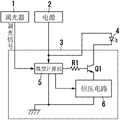
在图1中示出具备本实施方式的点亮装置3的照明装置的电路结构。FIG. 1 shows a circuit configuration of a lighting device including a
本实施方式的照明装置由调光器1、电源2、点亮装置(LED点亮装置)3以及多个(在本实施方式中为6个)LED负载4(4-1~4-6)构成。The lighting device of this embodiment is composed of a
LED负载4例如是半导体发光元件。多个LED负载4(4-1~4-6)互相并联连接。多个LED负载4-1~4-6构成光源9。换句话说,光源9具备利用直流电力发光的多个发光元件(LED负载)4。此外,发光元件并不限定为LED负载4。The
另外,LED点亮装置3由微型计算机(microcomputer)5、恒压电路6、多个(在本实施方式中为6个)电阻R1~R6以及多个(在本实施方式中为6个)晶体管(开关元件)Q1~Q6构成。In addition, the
恒压电路6构成为输出根据来自微型计算机5的信号所指定的恒定电压。恒压电路6构成对多个发光元件(LED负载)4中的各个发光元件供给电流的电流调整单元。The
多个晶体管(开关元件)Q1~Q6分别与多个发光元件(LED负载)4-1~4-6串联连接。具体地说,晶体管Q1~Q6被分别连接在LED负载4-1~4-6的阴极与地之间。多个晶体管Q1~Q6构成开关电路7(开关单元)。此外,多个电阻R1~R6被分别连接在多个晶体管Q1~Q6与微型计算机5之间。A plurality of transistors (switching elements) Q1 to Q6 are respectively connected in series to a plurality of light emitting elements (LED loads) 4-1 to 4-6. Specifically, the transistors Q1~Q6 are respectively connected between the cathodes of the LED loads 4-1~4-6 and the ground. A plurality of transistors Q1 to Q6 constitute a switching circuit 7 (switching means). In addition, the plurality of resistors R1 to R6 are respectively connected between the plurality of transistors Q1 to Q6 and the
在本实施方式中,恒压电路6(电流调整单元)和开关电路7(开关单元)构成使光源9点亮的点亮电路8。In this embodiment, the constant voltage circuit 6 (current adjustment means) and the switching circuit 7 (switching means) constitute a
微型计算机5是与调光比相应地控制光源9的调光控制单元。例如通过来自调光器1的调光信号对微型计算机5提供调光比。The
微型计算机5构成为利用点亮电路8控制光源9。微型计算机5构成为通过对向光源9供给的电流(供给电流)的大小和占空比中的至少一个进行调整来变更向光源9的供给电力。The
例如,微型计算机5构成为通过利用开关电路7对向光源9供给的电流的占空比进行调整来变更供给电力。另外,微型计算机5构成为通过利用恒压电路6对向光源9供给的电流的大小进行调整来变更供给电力。For example, the
这样,微型计算机5具有如下功能:读取调光器1的调光信号,对晶体管Q1~Q6的导通/截止进行控制,并且设定恒压电路6的电压值(设定电压)。Thus, the
如图2的(a)~(c)所示,在微型计算机5中具有预先决定的调光比(调光水平)Pa和调光水平Pb,在比该调光水平Pa明亮的区域(调光比为Pa~上限值的调光范围)内,微型计算机5通过使晶体管Q1~Q6固定为导通并改变恒压电路6的设定电压(输出电压)来使流经LED负载4-1~4-6中的每个LED负载的电流发生变化,由此进行DC调光。As shown in (a)-(c) of FIG. In the dimming range where the light ratio is Pa~the upper limit value), the
在比该调光水平Pa暗且比调光水平Pb明亮的区域(调光比为Pb~Pa的调光范围)内,微型计算机5通过使恒压电路6的设定电压固定并使晶体管Q1~Q6导通/截止来改变其占空比,由此以PWM调光的方式进行调光。In an area darker than the dimming level Pa and brighter than the dimming level Pb (the dimming range of the dimming ratio Pb to Pa), the
即,微型计算机5构成为:如果调光比包含在第一调光范围(Pb~上限值)内,则与调光比相应地变更向光源9的供给电力。That is, the
例如,调光比的上限值为100%。For example, the upper limit of the dimming ratio is 100%.
第一调光范围包括多个调光区间。在本实施方式中,第一调光范围包括第一调光区间和第二调光区间。例如,第一调光区间是调光比为Pa~100%的区间,第二调光区间是调光比为Pb~Pa的区间。The first dimming range includes multiple dimming intervals. In this embodiment, the first dimming range includes a first dimming interval and a second dimming interval. For example, the first dimming interval is an interval with a dimming ratio of Pa to 100%, and the second dimming interval is an interval with a dimming ratio of Pb to Pa.
第一调光区间是微型计算机5进行DC调光的区间(DC调光区间)。即,微型计算机5使点亮个数和占空比固定,并与调光比相应地改变供给电流的大小。The first dimming interval is an interval in which the
如果调光比包含在第一调光区间(Pa~上限值),则微型计算机5将点亮个数调整为与第一调光区间相关联的值(在本实施方式中为6),且将占空比调整为与第一调光区间相关联的值(在本实施方式中为与第二调光区间相关联的占空比的最大值[例如100%])。If the dimming ratio is included in the first dimming interval (Pa~upper limit), the
并且,微型计算机5将向光源9供给的电流(供给电流)的大小调整为与第一调光区间相关联的供给电流的范围内的与调光比相应的值。具体地说,微型计算机5调整恒压电路6的设定电压(输出电压),使得供给电流的大小成为与第一调光区间相关联的供给电流的范围内的与调光比相应的值。在第一调光区间,调光比越增大,则微型计算机5越增加供给电流(参照图2的(b))。Then, the
第二调光区间是微型计算机5进行PWM调光的区间(PWM调光区间)。即,微型计算机5使点亮个数和供给电流的大小固定,使占空比与调光比相应地变化。The second dimming period is a period in which the
如果调光比包含在第二调光区间(Pb~Pa),则微型计算机5将点亮个数调整为与第二调光区间相关联的值(在本实施方式中为6),且将供给电流的大小调整为与第二调光区间相关联的值(在本实施方式中为与第一调光区间相关联的供给电流的最小值)。If the dimming ratio is included in the second dimming interval (Pb~Pa), the
并且,微型计算机5将向光源9供给的电流(供给电流)的占空比调整为与第二调光区间相关联的占空比的范围内的与调光比相应的值。具体地说,微型计算机5对开关电路7的各开关元件(晶体管Q1~Q6)进行控制,使得占空比成为与第二调光区间相关联的占空比的范围内的与调光比相应的值。在第二调光区间,调光比越增大,则微型计算机5越增大占空比(参照图2的(c))。Then, the
另外,在比调光水平Pb暗的区域(调光比为下限值~Pb的调光范围)内,微型计算机5以间隔剔除调光(間引き調光)的方式进行调光,该间隔剔除调光是通过按开关元件Q1→开关元件Q2…Q6的顺序逐渐截止开关元件,来使LED的点亮个数发生变化。In addition, in an area darker than the dimming level Pb (dimming range in which the dimming ratio is the lower limit value to Pb), the
即,微型计算机5构成为:如果调光比包含在第二调光范围(下限值~Pb)内,则使向光源9的供给电力固定,并与调光比相应地变更点亮个数。例如,调光比的下限值为0%。第二调光范围是微型计算机5进行间隔剔除调光的区间(间隔剔除调光区间)。That is, the
在第二调光范围内,微型计算机5使供给电流的大小和占空比固定,由此使供给电力固定。因而,如果调光比包含在第二调光范围内,则微型计算机5将占空比调整为与第二调光范围相关联的值(在本实施方式中为与第二调光区间相关联的占空比的最小值),且将供给电流的大小调整为与第二调光范围相关联的值(在本实施方式中为与第一调光区间相关联的供给电流的最小值)。In the second dimming range, the
并且,微型计算机5将点亮个数调整为与第二调光范围相关联的点亮个数的范围内的与调光比相应的值。具体地说,微型计算机5对开关电路7的各开关元件(晶体管Q1~Q6)进行控制,使得点亮个数成为与第二调光范围相关联的点亮个数的范围内的与调光比相应的值。在第二调光范围内,调光比越减小,则微型计算机5越减少点亮个数。Then, the
即,微型计算机5构成为:如果调光比包含在与第一调光范围(Pb~上限值)不同的第二调光范围(下限值~Pb)内,则与调光比相应地变更要点亮的发光元件(LED负载)4的数量、即点亮个数。微型计算机5构成为利用开关电路7变更点亮个数。That is, the
在图2中示出本实施方式的点亮装置3的动作。图2的(a)示出了调光信号输出的水平(调光比)与光输出的关系,图2的(b)示出了调光信号输出的水平与流经LED负载4的导通期间(电流在LED负载4中流动的期间)的电流(峰值)的关系,图2的(c)示出了调光信号输出的水平与脉冲波形的导通占空比(对LED负载4供给的电流的占空比)的关系。The operation of the
例如根据LED元件的V-I特性来决定调光水平Pa的设定。设某个LED元件的V-I特性为如图3那样。在图3中,Vf是正向电压,If是正向电流。The setting of the dimming level Pa is determined, for example, according to the V-I characteristic of the LED element. Assume that the V-I characteristic of a certain LED element is as shown in FIG. 3 . In Figure 3, Vf is the forward voltage, If is the forward current.
将额定电流时的△V/△I设为A。如果将逐渐降低流经LED元件的电流时的△V/△I设为B,则随着降低流经LED元件的电流,B逐渐变大。Let ΔV/ΔI at the rated current be A. Assuming that ΔV/ΔI when the current flowing through the LED element is gradually reduced is B, B gradually increases as the current flowing through the LED element decreases.
当B的值相对于A的值为3倍~5倍以上时,LED元件变得不稳定,偏差也变大,因此,为了以DC调光的方式对没有变成这样的区域进行调光,对图2的调光水平Pa进行设定。When the value of B is 3 times to 5 times or more than the value of A, the LED element becomes unstable and the deviation becomes large. Therefore, in order to dim the areas that do not have such a situation by DC dimming, The dimming level Pa in FIG. 2 is set.
另外,关于调光水平Pb的设定,设定为微型计算机5能够稳定地控制脉冲宽度的最短的导通占空比(占空比)。在本实施方式中,光输出相对于调光占空比(%)直线下降,但不特别地限于直线,即使是在某种程度上具有曲线的特性也没有问题。In addition, the setting of the dimming level Pb is set to the shortest on-duty ratio (duty ratio) at which the
如上所述,本实施方式的点亮装置3是使多个半导体发光元件(LED负载4)点亮的点亮装置。本实施方式的点亮装置具备调光控制单元(微型计算机5),该调光控制单元接收从调光器1输出的调光信号来对DC调光和PWM调光中的某一种调光或者两种调光进行控制,其中,该DC调光是对流经半导体发光元件的电流的大小进行可变控制,该PWM调光是对流经半导体发光元件的电流进行间歇控制。在从调光器1输出的调光信号与规定水平相比更靠低亮度侧的情况下,本实施方式的点亮装置以减少半导体发光元件的点亮个数的间隔剔除调光的方式对半导体发光元件进行调光。As described above, the
换句话说,本实施方式的点亮装置3具备调光控制单元(微型计算机5),该调光控制单元与调光比相应地对具备利用直流电力发光的多个发光元件(LEF负载4)的光源9进行控制。调光控制单元(微型计算机5)构成为:如果调光比包含在第一调光范围内,则与调光比相应地变更向光源9的供给电力。调光控制单元(微型计算机5)构成为:如果调光比包含在与第一调光范围不同的第二调光范围内,则与调光比相应地变更要点亮的发光元件(LED负载4)的个数即点亮个数。In other words, the
根据如上所述的本实施方式的点亮装置,能够稳定地实现更深的调光。According to the lighting device of the present embodiment as described above, deeper dimming can be realized stably.
这样,在本实施方式中,能够提供如下一种LED调光装置:以DC调光和PWM调光的方式进行调光,并且进行间隔剔除调光,由此稳定地实现例如调光比为1%以下的更深的调光。In this way, in this embodiment, it is possible to provide an LED dimming device that performs dimming by means of DC dimming and PWM dimming, and performs thinning dimming, thereby stably realizing, for example, a dimming ratio of 1. % below for deeper dimming.
另外,在本实施方式的点亮装置3中,第二调光范围的上限值(在本实施方式中为Pb)为第一调光范围的下限值(在本实施方式中为Pb)以下。此外,该结构是任意结构。In addition, in the
另外,在本实施方式的点亮装置3中,调光控制单元(微型计算机5)构成为:在第二调光范围内,调光比越减小,则越是减少点亮个数。此外,该结构是任意结构。In addition, in the
另外,在本实施方式的点亮装置3中,调光控制单元(微型计算机5)构成为:通过对向光源9供给的电流的大小和占空比中的至少一个进行调整来变更供给电力。此外,该结构是任意结构。In addition, in the
另外,本实施方式的点亮装置3还具备使光源9点亮的点亮电路8。调光控制单元(微型计算机5)构成为利用点亮电路8来控制光源9。此外,该结构是任意结构。In addition, the
另外,在本实施方式的点亮装置3中,点亮电路8具备:电流调整单元(恒压电路6),其对多个发光元件(LED负载4)中的各个发光元件供给电流;以及开关单元(开关电路7),其具有分别与多个发光元件(LED负载4)串联连接的多个开关元件(晶体管Q1~Q6)。此外,该结构是任意结构。In addition, in the
另外,在本实施方式的点亮装置3中,调光控制单元(微型计算机5)构成为:通过利用开关单元(开关电路7)对向光源9供给的电流的占空比进行调整来变更供给电力。此外,该结构是任意结构。In addition, in the
另外,在本实施方式的点亮装置3中,调光控制单元(微型计算机5)构成为利用开关单元(开关电路7)来变更点亮个数。此外,该结构是任意结构。In addition, in the
另外,在本实施方式的点亮装置3中,调光控制单元(微型计算机5)构成为:通过利用电流调整单元(恒压电路6)对向光源9供给的电流的大小进行调整来变更供给电力。此外,该结构是任意结构。In addition, in the
另外,在本实施方式的点亮装置3中,通过来自调光器1的调光信号将调光比提供给调光控制单元(微型计算机5)。此外,该结构是任意结构。In addition, in the
此外,调光器1的调光信号输出既可以是模拟信号(DC0V~10V等),也可以是占空比信号(1KHZ、10V等),还可以是数字信号(DMX信号等)。In addition, the dimming signal output of the
另外,电源2既可以是AC电源也可以是DC电源。In addition, the
LED负载4(4-1~4-6)既可以是分别由一个元件构成的LED单元,也可以是分别由多个LED元件构成的LED单元。The LED loads 4 ( 4 - 1 to 4 - 6 ) may be LED units each composed of one element, or may be LED units each composed of a plurality of LED elements.
近年来,随着LED负载向大功率化发展,以串联和并联的方式使用很多LED的LED点亮装置3增加,因此通过间隔剔除调光来减小调光水平的方法变得有效。In recent years, as LED loads have increased in power,
另外,只要是能够利用DC电源、脉冲状的电源点亮的负载(即,用直流电力点亮的负载),就能够代替LED负载4(4-1~4-6)而替换为任意负载,即使是有机EL等也能够获得相同的效果。In addition, as long as it is a load that can be lit by a DC power supply or a pulse-shaped power supply (that is, a load that is lit by a DC power supply), any load can be substituted for the LED load 4 (4-1 to 4-6), The same effect can be obtained even with organic EL and the like.
在上述PWM调光中,流经LED的电流是矩形波,但该矩形波是最有效的波形,脉冲状的波形无论是正弦波形还是三角波形,只要是除了平坦的DC波形以外的波形就能够获得相同的效果。In the above-mentioned PWM dimming, the current flowing through the LED is a rectangular wave, but this rectangular wave is the most effective waveform, and the pulse-shaped waveform can be any waveform other than a flat DC waveform regardless of whether it is a sinusoidal waveform or a triangular waveform. to get the same effect.
另外,不仅可以包括以固定的PWM频率改变导通占空比的方式,还可以包括通过PWM频率的变化、导通期间或截止期间的变化来进行调光的方式。In addition, not only the method of changing the on-duty ratio with a fixed PWM frequency may be included, but also the method of dimming light by changing the PWM frequency and changing the on-period or off-period.
(实施方式2)(Embodiment 2)
在图4中示出具备本实施方式的点亮装置3的照明装置的电路结构。FIG. 4 shows a circuit configuration of a lighting device including the
本实施方式的照明装置由调光器1、电源2、点亮装置(LED点亮装置)3以及多个(在本实施方式中为5个)LED负载4(4-1~4-5)构成。The lighting device of this embodiment is composed of a
多个LED负载4(4-1~4-5)构成光源9。多个LED负载4(4-1~4-5)互相串联连接。LED负载4-1的阴极连接有LED负载4-2的阳极,LED负载4-2的阴极连接有LED负载4-3的阳极,LED负载4-3的阴极连接有LED负载4-4的阳极,LED负载4-4的阴极连接有LED负载4-5的阳极。A plurality of LED loads 4 ( 4 - 1 to 4 - 5 ) constitute a light source 9 . A plurality of LED loads 4 (4-1~4-5) are connected in series with each other. The cathode of the LED load 4-1 is connected to the anode of the LED load 4-2, the cathode of the LED load 4-2 is connected to the anode of the LED load 4-3, and the cathode of the LED load 4-3 is connected to the anode of the LED load 4-4 , the cathode of the LED load 4-4 is connected to the anode of the LED load 4-5.
另外,LED点亮装置3由微型计算机5、恒流电路6A、多个(在本实施方式中为10个)电阻R1~R5、R11~R15以及MOSFET等多个(在本实施方式中为5个)半导体开关元件(开关元件)Q1~Q5构成。In addition, the
恒流电路6A构成为使根据来自微型计算机5的电压信号所指定的恒定电流(设定电流)流动。恒流电路6A构成对多个发光元件(LED负载)4中的各个发光元件供给电流的电流调整单元。The constant
多个开关元件Q1~Q5构成开关单元(开关电路7)。开关元件Q1被连接在LED负载4-1、4-2的连接点与恒流电路6A之间。开关元件Q2被连接在LED负载4-2、4-3的连接点与恒流电路6A之间。开关元件Q3被连接在LED负载4-3、4-4的连接点与恒流电路6A之间。开关元件Q4被连接在LED负载4-4、4-5的连接点与恒流电路6A之间。开关元件Q5被连接在LED负载4-5的阴极与恒流电路6A之间。A plurality of switching elements Q1 to Q5 constitute a switching unit (switching circuit 7 ). Switching element Q1 is connected between the connection point of LED loads 4-1, 4-2 and constant
在开关电路7中,如果开关元件Q5导通而剩余的开关元件Q1~Q4截止,则LED负载4-1~4-5全部点亮,因此点亮个数为5个。如果开关元件Q4导通而剩余的开关元件Q1~Q3、Q5截止,则仅LED负载4-1~4-4点亮,因此点亮个数为4个。如果开关元件Q3导通而剩余的开关元件Q1、Q2、Q4、Q5截止,则仅LED负载4-1~4-3点亮,因此点亮个数为3个。如果开关元件Q2导通而剩余的开关元件Q1、Q3~Q5截止,则仅LED负载4-1、4-2点亮,因此点亮个数为2个。如果开关元件Q1导通而剩余的开关元件Q2~Q5截止,则仅LED负载4-1点亮,因此点亮个数为1个。In the
此外,多个电阻R1~R5被分别连接在多个开关元件Q1~Q5与微型计算机5之间。另外,多个电阻R11~R15被分别连接在多个开关元件Q1~Q5与恒流电路6A之间。In addition, the plurality of resistors R1 to R5 are respectively connected between the plurality of switching elements Q1 to Q5 and the
在本实施方式中,恒流电路6A(电流调整单元)和开关电路7(开关单元)构成使光源9点亮的点亮电路8。In the present embodiment, the constant
在本实施方式中,微型计算机5构成为通过利用开关电路7对向光源9供给的电流的占空比进行调整来变更供给电力。另外,微型计算机5构成为通过利用恒流电路6A对向光源9供给的电流的大小进行调整来变更供给电力。In the present embodiment, the
这样,微型计算机5具有如下功能:读取调光器1的调光信号,对开关元件Q1~Q5的导通/截止进行控制,并且设定恒流电路6A的电流值(设定电流)。Thus, the
如图5的(a)~(c)所示,微型计算机5构成为:如果调光比包含在第一调光范围(Pb~上限值)内,则与调光比相应地变更向光源9的供给电力。例如,调光比的上限值为100%。As shown in (a) to (c) of FIG. 5 , the
第一调光范围包括多个调光区间。在本实施方式中,第一调光范围包括第一调光区间和第二调光区间。例如,第一调光区间是调光比为Pa~100%的区间,第二调光区间是调光比为Pb~Pa的区间。The first dimming range includes multiple dimming intervals. In this embodiment, the first dimming range includes a first dimming interval and a second dimming interval. For example, the first dimming interval is an interval with a dimming ratio of Pa to 100%, and the second dimming interval is an interval with a dimming ratio of Pb to Pa.
第一调光区间是微型计算机5进行PWM调光的区间(PWM调光区间)。即,微型计算机5使点亮个数和供给电流的大小固定,与调光比相应地改变占空比。The first dimming period is a period in which the
如果调光比包含在第一调光区间(Pa~上限值),则微型计算机5将点亮个数调整为与第一调光区间相关联的值(在本实施方式中为5),且将供给电流的大小调整为与第一调光区间相关联的值(在本实施方式中为与第二调光区间相关联的供给电流的大小的最大值)。If the dimming ratio is included in the first dimming interval (Pa~upper limit), the
并且,微型计算机5将对光源9供给的电流(供给电流)的占空比调整为与第一调光区间相关联的占空比的范围内的与调光比相应的值。具体地说,微型计算机5对开关电路7的各开关元件Q1~Q5进行控制,使得占空比成为与第一调光区间相关联的占空比的范围内的与调光比相应的值。在第一调光区间,调光比越增大,则微型计算机5越增大占空比(参照图5的(c))。Then, the
第二调光区间是微型计算机5进行DC调光的区间(DC调光区间)。即,微型计算机5使点亮个数和占空比固定,与调光比相应地改变供给电流的大小。The second dimming interval is an interval in which the
如果调光比包含在第二调光区间(Pb~Pa),则微型计算机5将点亮个数调整为与第二调光区间相关联的值(在本实施方式中为5),且将占空比调整为与第二调光区间相关联的值(在本实施方式中为与第一调光区间相关联的占空比的最小值)。If the dimming ratio is included in the second dimming interval (Pb~Pa), the
并且,微型计算机5将对光源9供给的电流(供给电流)的大小调整为与第二调光区间相关联的供给电流的范围内的与调光比相应的值。具体地说,微型计算机5对恒流电路6A的设定电流(输出电流)进行调整,使得供给电流的大小成为与第二调光区间相关联的供给电流的范围内的与调光比相应的值。在第二调光区间,调光比越增大,则微型计算机5越增加供给电流(参照图5的(b))。Then, the
第二调光范围是微型计算机5进行间隔剔除调光的区间(间隔剔除调光区间)。即,微型计算机5使对光源9供给的电力固定,与调光比相应地变更点亮个数。例如,调光比的下限值为0%。The second dimming range is a section in which the
在第二调光范围内,微型计算机5使供给电流的大小和占空比固定,由此使供给电力固定。因而,如果调光比包含在第二调光范围内,则微型计算机5将占空比调整为与第二调光范围相关联的值(在本实施方式中为与第一调光区间相关联的占空比的最小值),且将供给电流的大小调整为与第二调光范围相关联的值(在本实施方式中为与第二调光区间相关联的供给电流的大小的最小值)。In the second dimming range, the
并且,微型计算机5将点亮个数调整为与第二调光范围相关联的点亮个数的范围内的与调光比相应的值。具体地说,微型计算机5对开关电路7的各开关元件Q1~Q5进行控制,使得点亮个数成为与第二调光范围相关联的点亮个数的范围内的与调光比相应的值。在第二调光范围内,调光比越减小,则微型计算机5越减少点亮个数。Then, the
即,微型计算机5构成为:如果调光比包含在与第一调光范围(Pb~上限值)不同的第二调光范围(下限值~Pb)内,则与调光比相应地变更要点亮的发光元件(LED负载4)的数量即点亮个数。微型计算机5构成为利用开关电路7变更点亮个数。That is, the
例如,为了进行平滑的调光,来自调光器1的调光信号具有256×256=65536的分辨率,将0~65535的数值数据用作调光水平的调光信号,将0设为熄灭,将65535设为100%点亮。For example, in order to perform smooth dimming, the dimming signal from dimmer 1 has a resolution of 256×256=65536, and the numerical data of 0~65535 is used as the dimming signal of the dimming level, and 0 is set as off , set 65535 to 100% on.
现在,在来自调光器1的信号为最大值65535的情况下,微型计算机5进行指示,使得开关元件Q1~Q5导通,且使最大电流(例如1A)流经恒流电路6A。于是,1A的电流在LED负载4中流动。Now, when the signal from the
接着,如果将调光水平减小至大约50%而作为调光信号的值接收到32768,则当微型计算机5使开关元件Q5导通/截止来将占空比设为50%时,LED负载4(4-1~4-5)的光大约也成为50%。Next, if the dimming level is reduced to about 50% and 32768 is received as the value of the dimming signal, when the
在将调光水平进一步减小至一半而作为调光信号的值接收到16384的信号的情况下,当将占空比设为25%时,LED负载4(4-1~4-5)的明亮度大约成为25%。When the dimming level is further reduced to half and a signal of 16384 is received as the value of the dimming signal, when the duty cycle is set to 25%, the LED load 4 (4-1~4-5) Brightness becomes about 25%.
在作为调光信号的值接收到6554的信号的情况下,当将占空比设为10%时,LED负载4(4-1~4-5)的明亮度大约成为10%。When a signal of 6554 is received as the value of the dimming signal, when the duty ratio is set to 10%, the brightness of the LED loads 4 (4-1 to 4-5) becomes about 10%.
此时,如果使开关元件Q5导通/截止的反复频率低,则会成为闪烁的原因,因此一般需要60HZ以上的反复频率。At this time, if the repetition frequency of turning ON/OFF of the switching element Q5 is low, it will cause flickering, so a repetition frequency of 60 Hz or more is generally required.
在视觉上即使在100HZ的反复频率下也不产生闪烁,但为了在视频录像等中不出现闪烁,需要以更高的反复频率(300HZ以上等)来进行点亮熄灭。Visually, flicker does not occur even at a repetition frequency of 100HZ, but in order to prevent flicker during video recording, etc., it is necessary to turn on and off at a higher repetition frequency (300HZ or more, etc.).
如果作为不产生闪烁的频率而将反复频率设为1000HZ,则即使减小至占空比10%,导通期间的脉冲宽度也为100μ秒,因此利用普通的微型计算机就能够容易地进行稳定的调光。另外,如果假设将开关元件Q1的响应速度设为10n秒,则对调光比的影响小到可忽视的程度。If the repetition frequency is set to 1000 Hz as the frequency at which flicker does not occur, even if the duty ratio is reduced to 10%, the pulse width during the conduction period is 100 μs. Therefore, it is easy to perform stable operation with an ordinary microcomputer. Dimming. In addition, assuming that the response speed of the switching element Q1 is set to 10n seconds, the influence on the dimming ratio is negligibly small.
在将调光水平进一步减小至一半而作为调光信号的值接收到3277的信号的情况下,进行指示以使一半电流即500mA流经恒流电路6,电流值变为最大电流值的50%(LED的光输出为5%)。When the dimming level is further reduced to half and the signal of 3277 is received as the value of the dimming signal, an instruction is made to flow a half current, that is, 500 mA, through the constant
在进一步减小调光水平而作为调光信号的值接收到655的信号的情况下,进行指示以使电流100mA流经恒流电路6A,由此能够使电流值变为最大电流值的10%(LED的光输出为1%)。When the dimming level is further decreased and a signal of 655 is received as the value of the dimming signal, an instruction is made to flow a current of 100 mA through the constant
接着,在进一步减小调光水平的情况下,通过使开关元件Q5截止(此时用Q4进行导通/截止控制),串联连接5个而成的LED负载(或者LED负载群)变为串联连接4个而成的LED负载,因此LED负载的光输出为0.8%。Next, in the case of further reducing the dimming level, by turning off the switching element Q5 (at this time, Q4 is used for ON/OFF control), the LED load (or LED load group) consisting of five serially connected becomes a series LED load.
另外,通过使开关元件Q4截止(此时用Q3进行导通/截止控制),LED负载的光输出变为0.6%,通过使开关元件Q3和Q2截止(此时用Q1进行导通/截止控制),能够调光至0.2%。In addition, by turning off switching element Q4 (at this time, Q3 is used for on/off control), the light output of the LED load becomes 0.6%, and by turning off switching elements Q3 and Q2 (at this time, Q1 is used for on/off control). ), capable of dimming to 0.2%.
在图5中示出本实施方式的点亮装置3的动作。图5的(a)示出了调光信号输出的水平(调光比)与光输出的关系,图5的(b)示出了调光信号输出的水平与流经LED负载的导通期间(电流在LED负载4中流动的期间)的电流(峰值)的关系,图5的(c)示出了调光信号输出的水平与导通占空比(对LED负载4供给的电流的占空比)的关系。通过设为上述结构,能够提供稳定地实现更深的调光的LED调光装置。The operation of the
在实施方式1和实施方式2的点亮装置3中,在将DC调光和PWM调光这两者相组合来进行调光之后进行间隔剔除调光,但即使在以DC调光和PWM调光中的某个方式进行调光之后进行间隔剔除调光也能够获得相同的效果。In the
另外,既可以一边同时改变DC调光和PWM调光一边进行调光,也可以一边改变DC调光或者PWM调光一边进行间隔剔除调光,均能够获得相同的效果。In addition, the dimming can be performed while simultaneously changing the DC dimming and the PWM dimming, or the thinning dimming can be performed while changing the DC dimming or the PWM dimming, both of which can obtain the same effect.
此外,点亮装置3也可以是反激(flyback)型DC-DC变换器、正向(forward)型DC-DC变换器等进行恒流控制和恒压控制的电路方式。In addition, the
(实施方式3)(Embodiment 3)
在本实施方式的点亮装置(LED点亮装置)3中,将电路结构设为与实施方式1或者实施方式2的点亮装置3的结构相同并省略说明。利用图6和图7说明本实施方式的点亮装置3的动作。图6和图7放大地示出低调光比(深调光)的部分。In the lighting device (LED lighting device) 3 of this embodiment, the circuit configuration is the same as that of the
如图6的(a)、(b)所示,第二调光范围(下限值~Pb)包括点亮个数各不相同的多个(在本实施方式中为5个)副调光区间。例如,第二调光范围包括第一副调光区间(Pc~Pb)、第二副调光区间(Pd~Pc)、第三副调光区间(Pe~Pd)、第四副调光区间(Pf~Pe)以及第五副调光区间(下限值~Pf)。As shown in (a) and (b) of Figure 6, the second dimming range (lower limit ~ Pb) includes multiple (five in this embodiment) sub-dimming with different numbers of lights. interval. For example, the second dimming range includes a first sub-dimming interval (Pc~Pb), a second sub-dimming interval (Pd~Pc), a third sub-dimming interval (Pe~Pd), a fourth sub-dimming interval (Pf~Pe) and the fifth secondary dimming interval (lower limit~Pf).
微型计算机5(调光控制单元)在副调光区间将点亮个数调整为与副调光区间相关联的值。并且,微型计算机5将对各发光元件(LED负载)4供给的单位电力在与副调光区间相关联的规定的变化宽度内与调光比相应地进行变更。The microcomputer 5 (dimming control unit) adjusts the number of lights to a value associated with the sub-dimming interval in the sub-dimming interval. Then, the
在图6所示的例子中,微型计算机5利用电流调整单元(实施方式1中的恒压电路6或者实施方式2中的恒流电路6A)对向各发光元件(LED负载)4供给的电流(单位电流)的大小进行调整,由此变更单位电力。In the example shown in FIG. 6 , the
也就是说,副调光区间是微型计算机5进行DC调光的区间(DC调光区间)。微型计算机5使点亮个数和占空比固定,与调光比相应地改变单位电流的大小。另外,在副调光区间,调光比越减小,则微型计算机5越减少单位电流(单位电力)。That is, the sub dimming section is a section in which the
微型计算机5将点亮个数调整为与副调光区间相关联的值,且将占空比调整为与副调光区间相关联的值。并且,微型计算机5在副调光区间将单位电流的大小调整为与副调光区间相关联的单位电流的范围内的与调光比相应的值。The
与第一副调光区间(Pc~Pb)相关联的点亮个数为5个,与第二副调光区间(Pd~Pc)相关联的点亮个数为4个,与第三副调光区间(Pe~Pd)相关联的点亮个数为3个,与第四副调光区间(Pf~Pe)相关联的点亮个数为2个,与第五副调光区间(下限值~Pf)相关联的点亮个数为1个。The number of lights associated with the first sub-dimming interval (Pc~Pb) is 5, the number of lights associated with the second sub-dimming interval (Pd~Pc) is 4, and the number of lights associated with the third sub-dimming interval The number of lightings associated with the dimming interval (Pe~Pd) is 3, the number of lightings associated with the fourth sub-dimming interval (Pf~Pe) is 2, and the number of lightings associated with the fifth sub-dimming interval ( The number of lights associated with the lower limit ~Pf) is 1.
多个副调光区间具有相同的占空比。与副调光区间相关联的占空比例如是第一调光范围的PWM调光区间(在实施方式1中为第二调光区间,在实施方式2中为第一调光区间)的占空比的最小值。此外,多个副调光区间也可以具有不同的占空比。Multiple secondary dimming intervals have the same duty cycle. The duty ratio associated with the sub-dimming section is, for example, the duty of the PWM dimming section of the first dimming range (the second dimming section in
多个副调光区间具有相同的单位电流的范围。与副调光区间相关联的单位电流的范围例如是下限值IL~上限值IH。因而,多个副调光区间具有相同的单位电力的范围。此外,多个副调光区间也可以具有不同的单位电流的范围。此外,单位电流的上限值IH例如是与第一调光范围的DC调光区间的供给电流的最小值相对应的值以下。The multiple sub-dimming intervals have the same unit current range. The range of the unit current associated with the sub-dimming interval is, for example, a lower limit IL to an upper limit IH . Therefore, the plurality of sub-dimming sections have the same range of unit electric power. In addition, the multiple sub-dimming intervals may also have different unit current ranges. In addition, the upper limit value IH of the unit current is, for example, equal to or less than a value corresponding to the minimum value of the supply current in the DC dimming section of the first dimming range.
例如,在调光比包含在第二副调光区间的情况下,微型计算机5将点亮个数调整为4个,并且调整为第一调光范围的PWM调光区间的占空比的最小值。并且,微型计算机5将单位电流的大小变更为与第二副调光区间相关联的单位电流的范围IL~IH中的与调光比相应的值。For example, when the dimming ratio is included in the second sub-dimming interval, the
在调光比为第二副调光区间的最小值的情况下,点亮个数为与第二副调光区间相对应的4个,占空比为PWM调光区间的占空比的最小值,单位电流的大小为IL。When the dimming ratio is the minimum value of the second sub-dimming interval, the number of lights is 4 corresponding to the second sub-dimming interval, and the duty ratio is the minimum duty ratio of the PWM dimming interval. value, the size of the unit current is IL .
另一方面,在调光比减小而成为第三副调光区间的最大值的情况下,点亮个数减少为与第三副调光区间相对应的3个,占空比不发生变化,单位电流的大小增加至IH。On the other hand, when the dimming ratio decreases to reach the maximum value in the third sub-dimming section, the number of lights is reduced to 3 corresponding to the third sub-dimming section, and the duty ratio does not change. , the magnitude of the unit current increases to IH .
即,虽然点亮个数从4个减少到3个,但单位电流的大小从IL增加至IH。在此,决定单位电流的上限值IH和下限值IL,使得随着调光比的减小而使光源9的明亮度连续地减小。即,决定单位电流的范围(换句话说,单位电力的范围),使得当减少点亮个数时光源9的明亮度的减小为规定值以下。例如,选择规定值,使得能够视为光源9的明亮度连续地变化。That is, although the numberof lit objects decreases from 4 to 3, the magnitude of the unit current increases from IL to IH. Here, the upper limit IH and the lower limit IL of the unit current are determined so that the brightness of the light source 9 decreases continuously as the dimming ratio decreases. That is, the range of the unit current (in other words, the range of the unit power) is determined so that the brightness of the light source 9 decreases below a predetermined value when the number of lights is reduced. For example, a predetermined value is selected so that the brightness of the light source 9 can be regarded as continuously changing.
在图6中示出了本实施方式的点亮装置3的调光特性图,进行控制使得在调光比为Pb~Pc的范围内减少导通期间的电流,以使调光连续,进行控制使得在调光比Pc下通过间隔剔除调光方式减少LED负载的点亮个数时,通过增加导通期间的电流而不损坏光的连续性。在调光比Pc~调光比Pf的范围内也同样地进行控制。FIG. 6 shows a dimming characteristic diagram of the
以上所述的本实施方式的点亮装置3还在减少半导体发光元件(LED负载4)的点亮个数时,通过DC调光和PWM调光中的某个方式或者这两个方式来调整流经半导体发光元件(LED负载4)的电流,使得不损坏光的连续性。The above-mentioned
换句话说,在本实施方式的点亮装置3中,调光控制单元(微型计算机5)构成为:当减少点亮个数时对供给电力进行调整,使得光源9的明亮度的减小为规定值以下。In other words, in the
另外,在本实施方式的点亮装置3中,选择规定值,使得能够视为光源9的明亮度连续地变化。此外,该结构是任意结构。In addition, in the
特别是在本实施方式的点亮装置3中,第二调光范围包括点亮个数各不相同的多个副调光区间。调光控制单元(微型计算机5)在副调光区间将点亮个数调整为与副调光区间相关联的值,且将对各发光元件(LED负载4)供给的单位电力变更为与副调光区间相关联的单位电力的范围内的与调光比相应的值。此外,该结构是任意结构。In particular, in the
另外,在本实施方式的点亮装置3中,决定单位电力的范围,使得当减少点亮个数时光源9的明亮度的减小为规定值以下。此外,该结构是任意结构。In addition, in the
另外,在本实施方式的点亮装置3中,选择规定值,使得能够视为光源9的明亮度连续地变化。此外,该结构是任意结构。In addition, in the
在本实施方式中,能够提供如下一种LED调光装置:能够进行控制,使得即使在调光至深调光时也不损坏光的连续性。In this embodiment, it is possible to provide an LED dimming device capable of performing control so that continuity of light is not impaired even when dimming to deep dimming.
在图7中示出了本实施方式的点亮装置3的变形例的调光特性图,是为了不损坏光的连续性而以调整导通占空比的方式进行控制的特性图,能够获得与调整导通期间的电流时相同的效果。FIG. 7 shows a dimming characteristic diagram of a modified example of the
即,在图7所示的例子中,微型计算机5通过利用开关电路7对向各发光元件(LED负载4)供给的电流的占空比进行调整来变更单位电力。That is, in the example shown in FIG. 7 , the
也就是说,副调光区间是微型计算机5进行PWM调光的区间(PWM调光区间)。微型计算机5使点亮个数和单位电流的大小固定,使单位电流的占空比(与供给电流的占空比相等)与调光比相应地变化。另外,在副调光区间,调光比越减小,则微型计算机5越减小占空比(单位电力)。That is, the sub dimming period is a period in which the
微型计算机5将点亮个数调整为与副调光区间相关联的值,且将单位电流的大小调整为与副调光区间相关联的值。并且,微型计算机5在副调光区间将单位电流的占空比调整为与副调光区间相关联的占空比的范围内的与调光比相应的值。The
多个副调光区间具有相同的单位电流的大小。与副调光区间相关联的单位电流的大小例如是与第一调光范围的DC调光区间(在实施方式1中为第一调光区间,在实施方式2中为第二调光区间)的供给电流的最小值相对应的值(即,供给电流为最小值时的单位电流)。此外,多个副调光区间也可以具有不同的单位电流的大小。The multiple sub-dimming intervals have the same unit current magnitude. The magnitude of the unit current associated with the sub-dimming interval is, for example, the DC dimming interval of the first dimming range (the first dimming interval in
多个副调光区间具有相同的占空比的范围。与副调光区间相关联的占空比的范围例如是下限值DL~上限值DH。因而,多个副调光区间具有相同的单位电力的范围。此外,多个副调光区间也可以具有不同的单位电流的占空比的范围。此外,占空比的上限值DH例如是第一调光范围的PWM调光区间的占空比的最小值以下。The multiple sub-dimming intervals have the same duty cycle range. The range of the duty ratio associated with the sub-dimming section is, for example, a lower limit value DL to an upper limit value DH . Therefore, the plurality of sub-dimming sections have the same range of unit electric power. In addition, the plurality of sub-dimming intervals may also have different ranges of duty ratios of the unit current. In addition, the upper limit value DH of the duty ratio is, for example, equal to or less than the minimum value of the duty ratio in the PWM dimming section of the first dimming range.
例如,在调光比包含在第二副调光区间的情况下,微型计算机5将点亮个数调整为4个,并且将单位电流调整为与第一调光范围内的DC调光区间的供给电流的最小值相对应的值。并且,微型计算机5将占空比变更为与第二副调光区间相关联的占空比的范围DL~DH内的与调光比相应的值。For example, when the dimming ratio is included in the second sub-dimming interval, the
在调光比为第二副调光区间的最小值的情况下,点亮个数为与第二副调光区间相对应的4个,单位电流为与DC调光区间的供给电流的最小值相对应的值,占空比为DL。When the dimming ratio is the minimum value of the second sub-dimming interval, the number of lights is 4 corresponding to the second sub-dimming interval, and the unit current is the minimum value of the supply current in the DC dimming interval Corresponding value, the duty cycle is DL .
另一方面,在调光比减小而成为第三副调光区间的最大值的情况下,点亮个数减少为与第三副调光区间相对应的3个,单位电流的大小不发生变化,占空比增加至DH。On the other hand, when the dimming ratio decreases to reach the maximum value of the third sub-dimming section, the number of lights is reduced to 3 corresponding to the third sub-dimming section, and the magnitude of the unit current does not change. change, the duty cycle increases to DH .
即,虽然点亮个数从4个减少到3个,但占空比从DL增加至DH。在此,决定占空比的上限值DH和下限值DL,使得随着调光比的减小而光源9的明亮度连续地减小。即,决定占空比的范围(换句话说,单位电力的范围),使得当减少点亮个数时光源9的明亮度的减小为规定值以下。例如,选择规定值,使得能够视为光源9的明亮度连续地变化。That is, although the number of lit objects decreases from 4 to 3, the duty ratio increases fromDL toDH . Here, the upper limit value DH and the lower limit valueDL of the duty ratio are determined so that the brightness of the light source 9 decreases continuously as the dimming ratio decreases. That is, the range of the duty ratio (in other words, the range of the unit electric power) is determined so that the brightness of the light source 9 decreases below a predetermined value when the number of lights is reduced. For example, a predetermined value is selected so that the brightness of the light source 9 can be regarded as continuously changing.
因而,即使在图7所示的变形例中也能够获得与图6所示的本实施方式的点亮装置3相同的效果。Therefore, also in the modified example shown in FIG. 7, the same effect as that of the
Claims (15)
Applications Claiming Priority (2)
| Application Number | Priority Date | Filing Date | Title |
|---|---|---|---|
| JP2011270476AJP2013122846A (en) | 2011-12-09 | 2011-12-09 | Lighting device |
| JP2011-270476 | 2011-12-09 |
Publications (2)
| Publication Number | Publication Date |
|---|---|
| CN103167688Atrue CN103167688A (en) | 2013-06-19 |
| CN103167688B CN103167688B (en) | 2015-06-03 |
Family
ID=47627907
Family Applications (1)
| Application Number | Title | Priority Date | Filing Date |
|---|---|---|---|
| CN201210530414.6AActiveCN103167688B (en) | 2011-12-09 | 2012-12-10 | Lighting apparatus |
Country Status (4)
| Country | Link |
|---|---|
| US (1) | US8803446B2 (en) |
| EP (1) | EP2603060A1 (en) |
| JP (1) | JP2013122846A (en) |
| CN (1) | CN103167688B (en) |
Cited By (3)
| Publication number | Priority date | Publication date | Assignee | Title |
|---|---|---|---|---|
| WO2015010456A1 (en)* | 2013-07-22 | 2015-01-29 | 深圳Tcl新技术有限公司 | Adjustment method for led backlight brightness |
| CN105913810A (en)* | 2016-06-08 | 2016-08-31 | 维沃移动通信有限公司 | Control method, control circuit, backlight integration circuit and terminal equipment |
| TWI577235B (en)* | 2014-03-13 | 2017-04-01 | 松下知識產權經營股份有限公司 | Dimming device and lighting system using the same |
Families Citing this family (12)
| Publication number | Priority date | Publication date | Assignee | Title |
|---|---|---|---|---|
| JP5884049B2 (en)* | 2011-12-05 | 2016-03-15 | パナソニックIpマネジメント株式会社 | Lighting device and lighting apparatus provided with the same |
| JP5942256B2 (en)* | 2012-06-08 | 2016-06-29 | パナソニックIpマネジメント株式会社 | Lighting device and lighting apparatus |
| US9788379B2 (en) | 2014-03-28 | 2017-10-10 | Xicato, Inc. | Deep dimming of an LED-based illumination device |
| EP2947966A1 (en)* | 2014-05-19 | 2015-11-25 | Elekno Oy | Led lighting device |
| JP2016146278A (en)* | 2015-02-09 | 2016-08-12 | サンケン電気株式会社 | LED drive device |
| JP6456197B2 (en)* | 2015-03-11 | 2019-01-23 | 株式会社デンソーテン | Image display system and image display method |
| JP6784967B2 (en)* | 2015-06-09 | 2020-11-18 | 天馬微電子有限公司 | LED backlight drive circuit and its drive method, and liquid crystal display device |
| US9844111B1 (en)* | 2015-07-24 | 2017-12-12 | Marvell International Ltd. | Dimmable LED driving system and method for reducing flicker |
| WO2018041505A1 (en) | 2016-09-01 | 2018-03-08 | Philips Lighting Holding B.V. | Spatial dimming. |
| JP6934131B2 (en)* | 2019-07-23 | 2021-09-15 | 英志 古川 | Lighting control device and lighting device |
| JP2021150154A (en)* | 2020-03-18 | 2021-09-27 | シャープ株式会社 | Display device |
| CN112469167B (en)* | 2020-12-09 | 2022-07-01 | 成都极米科技股份有限公司 | Voltage adjusting circuit and dimming circuit |
Citations (3)
| Publication number | Priority date | Publication date | Assignee | Title |
|---|---|---|---|---|
| WO2002051211A2 (en)* | 2000-12-20 | 2002-06-27 | Gestion Proche Inc. | Lighting device |
| CN101836505A (en)* | 2007-10-25 | 2010-09-15 | 松下电工株式会社 | LED dimming apparatus |
| US20100308739A1 (en)* | 2009-06-04 | 2010-12-09 | Exclara Inc. | Apparatus, Method and System for Providing AC Line Power to Lighting Devices |
Family Cites Families (8)
| Publication number | Priority date | Publication date | Assignee | Title |
|---|---|---|---|---|
| EP1353317A2 (en)* | 2002-04-08 | 2003-10-15 | Sun Microsystems, Inc. | Method and apparatus for dimming a lamp in a backlight of a liquid crystal display |
| ES2298987T3 (en)* | 2005-02-02 | 2008-05-16 | Patent-Treuhand-Gesellschaft Fur Elektrische Gluhlampen Mbh | METHOD AND SYSTEM TO DIMATE SOURCES OF LIGHT. |
| US7560677B2 (en)* | 2007-03-13 | 2009-07-14 | Renaissance Lighting, Inc. | Step-wise intensity control of a solid state lighting system |
| JP5047373B2 (en) | 2007-10-25 | 2012-10-10 | パナソニック株式会社 | LED dimmer |
| US8487546B2 (en)* | 2008-08-29 | 2013-07-16 | Cirrus Logic, Inc. | LED lighting system with accurate current control |
| US8508150B2 (en)* | 2008-12-12 | 2013-08-13 | O2Micro, Inc. | Controllers, systems and methods for controlling dimming of light sources |
| EP2233826B1 (en) | 2009-03-17 | 2015-12-16 | Thorn Europhane S.A. | Lighting unit and luminaire for road and/or street lighting |
| JP5480671B2 (en)* | 2010-03-03 | 2014-04-23 | パナソニック株式会社 | LED lighting device |
- 2011
- 2011-12-09JPJP2011270476Apatent/JP2013122846A/enactivePending
- 2012
- 2012-12-06EPEP12195791.4Apatent/EP2603060A1/ennot_activeCeased
- 2012-12-06USUS13/706,843patent/US8803446B2/enactiveActive
- 2012-12-10CNCN201210530414.6Apatent/CN103167688B/enactiveActive
Patent Citations (3)
| Publication number | Priority date | Publication date | Assignee | Title |
|---|---|---|---|---|
| WO2002051211A2 (en)* | 2000-12-20 | 2002-06-27 | Gestion Proche Inc. | Lighting device |
| CN101836505A (en)* | 2007-10-25 | 2010-09-15 | 松下电工株式会社 | LED dimming apparatus |
| US20100308739A1 (en)* | 2009-06-04 | 2010-12-09 | Exclara Inc. | Apparatus, Method and System for Providing AC Line Power to Lighting Devices |
Cited By (3)
| Publication number | Priority date | Publication date | Assignee | Title |
|---|---|---|---|---|
| WO2015010456A1 (en)* | 2013-07-22 | 2015-01-29 | 深圳Tcl新技术有限公司 | Adjustment method for led backlight brightness |
| TWI577235B (en)* | 2014-03-13 | 2017-04-01 | 松下知識產權經營股份有限公司 | Dimming device and lighting system using the same |
| CN105913810A (en)* | 2016-06-08 | 2016-08-31 | 维沃移动通信有限公司 | Control method, control circuit, backlight integration circuit and terminal equipment |
Also Published As
| Publication number | Publication date |
|---|---|
| JP2013122846A (en) | 2013-06-20 |
| US8803446B2 (en) | 2014-08-12 |
| EP2603060A1 (en) | 2013-06-12 |
| US20130147356A1 (en) | 2013-06-13 |
| CN103167688B (en) | 2015-06-03 |
Similar Documents
| Publication | Publication Date | Title |
|---|---|---|
| CN103167688B (en) | Lighting apparatus | |
| US8680787B2 (en) | Load control device for a light-emitting diode light source | |
| US8653739B2 (en) | Circuit for operating light emitting diodes (LEDs) | |
| JP5725736B2 (en) | LED power supply device and LED lighting apparatus | |
| US8339053B2 (en) | LED dimming apparatus | |
| CA2969102C (en) | Current splitter for led lighting system | |
| US8334659B2 (en) | Electronic driver dimming control using ramped pulsed modulation for large area solid-state OLEDs | |
| JP5665382B2 (en) | LED power supply device and LED lighting apparatus | |
| TWI533746B (en) | Controller and method for dimming and light source driving circuit thereof | |
| US8698409B2 (en) | Lighting device and lighting fixture using the same | |
| JP2009004483A (en) | Light emitting diode drive circuit | |
| US20110025230A1 (en) | Driver device for leds | |
| CN104427720B (en) | Lighting device and illumination apparatus using the same | |
| US8816604B2 (en) | Dimming control method and apparatus for LED light source | |
| CN103222341A (en) | LED lighting device and LED lighting device | |
| KR20110092156A (en) | LED lighting control system | |
| JP5538078B2 (en) | LED power supply | |
| JP2013254717A (en) | Lighting device and luminaire | |
| JP2012074693A (en) | Driver circuit for light-emitting component | |
| WO2012153594A1 (en) | Lighting device | |
| CN104427722B (en) | Lighting device and illumination apparatus using the same | |
| KR20140107837A (en) | Led lighting system and control circuit thereof | |
| JP7463844B2 (en) | Lighting devices and luminaires | |
| JP2007266088A (en) | Lighting system and illuminator for organic el | |
| JP2007251036A (en) | Organic el lighting device and illuminator |
Legal Events
| Date | Code | Title | Description |
|---|---|---|---|
| C06 | Publication | ||
| PB01 | Publication | ||
| C10 | Entry into substantive examination | ||
| SE01 | Entry into force of request for substantive examination | ||
| C14 | Grant of patent or utility model | ||
| GR01 | Patent grant | ||
| ASS | Succession or assignment of patent right | Owner name:PANASONIC INTELLECTUAL PROPERTY MANAGEMENT CO., LT Free format text:FORMER OWNER: MATSUSHITA ELECTRIC INDUSTRIAL CO, LTD. Effective date:20150907 | |
| C41 | Transfer of patent application or patent right or utility model | ||
| TR01 | Transfer of patent right | Effective date of registration:20150907 Address after:Osaka Japan Patentee after:PANASONIC INTELLECTUAL PROPERTY MANAGEMENT Co.,Ltd. Address before:Osaka Japan Patentee before:Matsushita Electric Industrial Co.,Ltd. |