CN103163945A - Electronic device and fan module of the same - Google Patents
Electronic device and fan module of the sameDownload PDFInfo
- Publication number
- CN103163945A CN103163945ACN201110411710XACN201110411710ACN103163945ACN 103163945 ACN103163945 ACN 103163945ACN 201110411710X ACN201110411710X ACN 201110411710XACN 201110411710 ACN201110411710 ACN 201110411710ACN 103163945 ACN103163945 ACN 103163945A
- Authority
- CN
- China
- Prior art keywords
- fan
- mounting frame
- fixing
- buckle
- piece
- Prior art date
- Legal status (The legal status is an assumption and is not a legal conclusion. Google has not performed a legal analysis and makes no representation as to the accuracy of the status listed.)
- Granted
Links
Images


Classifications
- H—ELECTRICITY
- H05—ELECTRIC TECHNIQUES NOT OTHERWISE PROVIDED FOR
- H05K—PRINTED CIRCUITS; CASINGS OR CONSTRUCTIONAL DETAILS OF ELECTRIC APPARATUS; MANUFACTURE OF ASSEMBLAGES OF ELECTRICAL COMPONENTS
- H05K7/00—Constructional details common to different types of electric apparatus
- H05K7/20—Modifications to facilitate cooling, ventilating, or heating
- H05K7/20009—Modifications to facilitate cooling, ventilating, or heating using a gaseous coolant in electronic enclosures
- H05K7/20136—Forced ventilation, e.g. by fans
- H05K7/20172—Fan mounting or fan specifications
Landscapes
- Engineering & Computer Science (AREA)
- Microelectronics & Electronic Packaging (AREA)
- Physics & Mathematics (AREA)
- Thermal Sciences (AREA)
- Cooling Or The Like Of Electrical Apparatus (AREA)
Abstract
Translated fromChinese
Description
Translated fromChinese技术领域technical field
本发明涉及一种电子装置及其风扇模组。The invention relates to an electronic device and a fan module thereof.
背景技术Background technique
随着IT产业的快速发展,服务器等电子装置内的电子元件(如中央处理器、硬盘及显卡等)的高速、高频及集成化使其发热量剧增,如不及时散热,会影响电子装置的正常运行。目前,通常利用螺丝将风扇固定于服务器机箱内,以散发电子元件产生的热量。这种安装方式,使拆装风扇非常不便。With the rapid development of the IT industry, the high-speed, high-frequency and integration of electronic components (such as central processing unit, hard disk and graphics card, etc.) in electronic devices such as servers will cause a sharp increase in heat generation. normal operation of the device. At present, the fan is usually fixed in the server chassis by screws to dissipate the heat generated by the electronic components. This installation method makes it very inconvenient to disassemble and assemble the fan.
发明内容Contents of the invention
鉴于以上内容,有必要提供一种风扇拆装方便的电子装置及其风扇模组。In view of the above, it is necessary to provide an electronic device with a fan that can be easily disassembled and assembled, and a fan module thereof.
一种风扇模组,可拆卸地插设于一电子装置的机箱内,机箱包括一开设有卡槽的侧板,所述风扇模组包括一安装架、一固定于安装架的风扇及一夹置于安装架与风扇之间的卡扣件,安装架开设一通槽,卡扣件凸设一可穿过该通槽卡扣于机箱的卡槽的楔形的卡扣片。A fan module is detachably inserted into a case of an electronic device, the case includes a side plate provided with a card slot, the fan module includes a mounting frame, a fan fixed on the mounting frame and a clip As for the buckle part placed between the installation frame and the fan, the installation frame defines a through slot, and the buckle part is protruded with a wedge-shaped buckle piece that can pass through the through slot and be buckled into a slot of the chassis.
一种电子装置,包括一机箱及一可拆卸地插设于机箱内的风扇模组,机箱包括一收容部,收容部包括一开设有卡槽的侧板,所述风扇模组容置于收容部内,所述风扇模组包括一安装架、一固定于安装架的第一侧的风扇及一卡扣件,安装架开设一通槽,卡扣件贴附于安装架的第一侧并朝向安装架凸设一楔形的卡扣片,卡扣片穿过安装架的通槽后可卡扣于机箱的侧板的卡槽内。An electronic device, comprising a case and a fan module detachably inserted in the case, the case includes a receiving portion, the receiving portion includes a side plate with a card slot, the fan module is accommodated in the receiving Inside, the fan module includes a mounting frame, a fan fixed on the first side of the mounting frame, and a buckle. A wedge-shaped buckle piece protrudes from the frame, and the buckle piece passes through the through slot of the mounting frame and can be buckled in the slot of the side plate of the chassis.
相较现有技术,本发明风扇模组利用安装架配合卡扣件可方便地将风扇模组装拆于电子装置的机箱,使用方便。Compared with the prior art, the fan module of the present invention can be conveniently assembled and disassembled from the case of the electronic device by using the mounting frame and the buckle, which is convenient to use.
附图说明Description of drawings
下面参照附图结合具体实施方式对本发明作进一步的描述。The present invention will be further described below in conjunction with specific embodiments with reference to the accompanying drawings.
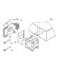
图1为本发明电子装置及其风扇模组的具体实施方式的立体分解图。FIG. 1 is a three-dimensional exploded view of a specific embodiment of the electronic device and its fan module of the present invention.
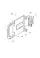
图2为图1的另一视角的立体分解图。FIG. 2 is an exploded perspective view from another perspective of FIG. 1 .
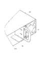
图3为图1中的风扇模组的局部组装示意图。FIG. 3 is a partial assembly diagram of the fan module in FIG. 1 .
图4为图1的局部组装示意图。FIG. 4 is a partial assembly diagram of FIG. 1 .
图5为图1的立体组装图。FIG. 5 is a perspective assembly view of FIG. 1 .
主要元件符号说明Description of main component symbols
如下具体实施方式将结合上述附图进一步说明本发明。The following specific embodiments will further illustrate the present invention in conjunction with the above-mentioned drawings.
具体实施方式Detailed ways
请参照图1及图2,本发明电子装置包括一机箱100以及装设于机箱100内的一风扇模组200。Please refer to FIG. 1 and FIG. 2 , the electronic device of the present invention includes a
该机箱100设有一方形的收容部101用于收容风扇模组200。收容部101包括一侧板103。侧板103开设两平行的卡槽1031。The
该风扇模组200包括一风扇10、一安装架20、一卡扣件30及两锁固件40。锁固件40为螺栓。The
该风扇10包括两固定板12,每一固定板12的四角分别开设一固定孔122。每一固定板12的每一侧边中部相连形成一抵接面14。The
该安装架20包括一基板22。基板22的第一端设置一环形的操作部24。基板22包括相对的第一侧221及第二侧222。基板22的第一侧221凸设一凸台26并于凸台26的上下两侧分别开设一通槽27。基板22的第二端中部沿基板22方向凸伸并向第一侧221弯折形成一垂直于基板22的固持片28。固持片28上固设一连接器50。基板22的第二端两侧分别向第一侧221凸设一垂直于基板22的固定片29。每一固定片29开设一锁固孔291。The
卡扣件30概呈片状,其中部开设一通孔31并于通孔31的两侧壁分别垂直凸设一楔形的卡扣片32。卡扣件30的一端凸设一扳动部33。The
请一并参阅图3至图5,组装风扇模组200时,将卡扣件30贴附于安装架20的基板22的第一侧221,使基板22的凸台26穿过卡扣件30的通孔31,并使两卡扣片32分别穿过基板22的两通槽27后外露于基板22的第二侧222。将风扇10贴附于安装架20,使风扇10的两固定板12均垂直于安装架20。风扇10的其中一固定板12外侧抵顶于安装架20的两固定片29,并使固定板12的靠近卡扣件30一侧的两固定孔122分别对准固定片29的锁固孔291。利用两锁固件40分别穿过风扇10的靠近安装架20的固定孔122锁入固定片29的锁固孔291内,将风扇10锁固于安装架20,风扇10的靠近卡扣件30的抵接面14抵接于凸台26。凸台26与抵接面14抵接之后安装架20的第一侧221与风扇10之间的空间能使卡扣件30发生弹性变形以使卡扣片32自卡槽1031内脱离。风扇10的连接器插接于连接器50。Please refer to FIG. 3 to FIG. 5 together. When assembling the
将风扇模组200置入收容部101内,卡扣片32抵接于侧板103后发生弹性变形,直至卡扣片32卡扣于卡槽1031,则将风扇模组200组装于机箱100内。风扇模组200的连接器50可插接于机箱100内的电路板(图未示)进而与机箱100电性连接。Put the
需要拆卸风扇模组200时,握住操作部24并扳动扳动部33使卡扣件30发生弹性变形至卡扣片32自卡槽1031内脱离,进而可将风扇模组200自机箱100内拉出。When the
在其它实施方式中,安装架20上可以直接固设一弹片,弹片设有卡扣片以实现卡扣件30的功能。In other embodiments, an elastic piece can be fixed directly on the
Claims (10)
Translated fromChinesePriority Applications (3)
| Application Number | Priority Date | Filing Date | Title |
|---|---|---|---|
| CN201110411710.XACN103163945B (en) | 2011-12-12 | 2011-12-12 | Electronic device and its fan module |
| TW100146440ATW201323733A (en) | 2011-12-12 | 2011-12-15 | Electronic device and fan module of the same |
| US13/337,263US20130149168A1 (en) | 2011-12-12 | 2011-12-26 | Mounting apparatus for fan |
Applications Claiming Priority (1)
| Application Number | Priority Date | Filing Date | Title |
|---|---|---|---|
| CN201110411710.XACN103163945B (en) | 2011-12-12 | 2011-12-12 | Electronic device and its fan module |
Publications (2)
| Publication Number | Publication Date |
|---|---|
| CN103163945Atrue CN103163945A (en) | 2013-06-19 |
| CN103163945B CN103163945B (en) | 2016-11-16 |
Family
ID=48572145
Family Applications (1)
| Application Number | Title | Priority Date | Filing Date |
|---|---|---|---|
| CN201110411710.XAActiveCN103163945B (en) | 2011-12-12 | 2011-12-12 | Electronic device and its fan module |
Country Status (3)
| Country | Link |
|---|---|
| US (1) | US20130149168A1 (en) |
| CN (1) | CN103163945B (en) |
| TW (1) | TW201323733A (en) |
Cited By (3)
| Publication number | Priority date | Publication date | Assignee | Title |
|---|---|---|---|---|
| CN105514732A (en)* | 2015-12-08 | 2016-04-20 | 英业达科技有限公司 | Fan connector connection structure |
| CN108825555A (en)* | 2018-08-15 | 2018-11-16 | 东菱技术有限公司 | A kind of mounting structure of fan cover in driver radiator |
| CN113985987A (en)* | 2021-11-09 | 2022-01-28 | 苏州浪潮智能科技有限公司 | Fan modules and electronic equipment |
Families Citing this family (8)
| Publication number | Priority date | Publication date | Assignee | Title |
|---|---|---|---|---|
| CN103186205A (en)* | 2011-12-28 | 2013-07-03 | 鸿富锦精密工业(深圳)有限公司 | Fan module fixing device |
| CN103313579A (en)* | 2012-03-15 | 2013-09-18 | 鸿富锦精密工业(深圳)有限公司 | Electronic device and fan module thereof |
| CN104632684B (en)* | 2013-11-08 | 2017-02-15 | 英业达科技有限公司 | Fan module and main case using same |
| US10165696B1 (en)* | 2017-08-10 | 2018-12-25 | Adtran, Inc. | Removable module with spring latch |
| CN110879648B (en)* | 2018-09-06 | 2024-01-23 | 联想企业解决方案(新加坡)有限公司 | Computing system, device and electronic component thereof |
| US11852186B1 (en)* | 2020-06-03 | 2023-12-26 | ZT Group Int'l, Inc. | Dial cam latch |
| KR20220015567A (en)* | 2020-07-31 | 2022-02-08 | 엘지이노텍 주식회사 | Power module |
| US12016152B2 (en)* | 2021-05-21 | 2024-06-18 | Runbeck Election Services Inc. | Cooling system for a printer |
Citations (3)
| Publication number | Priority date | Publication date | Assignee | Title |
|---|---|---|---|---|
| CN2849262Y (en)* | 2005-09-21 | 2006-12-20 | 鸿富锦精密工业(深圳)有限公司 | Fixing device of fan |
| US20090122485A1 (en)* | 2007-11-14 | 2009-05-14 | Inventec Corporation | Fixing frame |
| CN201349390Y (en)* | 2009-01-07 | 2009-11-18 | 鸿富锦精密工业(深圳)有限公司 | Heat dissipating device |
Family Cites Families (15)
| Publication number | Priority date | Publication date | Assignee | Title |
|---|---|---|---|---|
| US2968457A (en)* | 1957-11-18 | 1961-01-17 | Krauss Carl | Motor bracket assembly for fans |
| US6322042B1 (en)* | 2000-07-19 | 2001-11-27 | Lite-On Enclosure Inc. | Extracted and positioning device of a fan |
| US6611427B1 (en)* | 2002-06-03 | 2003-08-26 | Accton Technology Corporation | Flexible fan module |
| US6999313B2 (en)* | 2003-04-22 | 2006-02-14 | Epserv Tech Corporation | Signal connection assembly of cooling module |
| US7530890B2 (en)* | 2004-06-30 | 2009-05-12 | Shuttle Inc. | Quickly detached cooling fan mounting bracket for computer |
| TWM263554U (en)* | 2004-12-30 | 2005-05-01 | Inventec Corp | Fixing device for heat dissipation fan of server |
| US7623344B2 (en)* | 2005-08-09 | 2009-11-24 | Dell Products L.P. | Method and apparatus for mounting a fan in a chassis |
| US7251135B2 (en)* | 2005-09-08 | 2007-07-31 | International Business Machines Corporation | Easy release server cooling fan with integrated spring and method for using same |
| US7522415B2 (en)* | 2006-07-13 | 2009-04-21 | Hon Hai Precision Industry Co., Ltd. | Mounting assembly for fan |
| TWI314186B (en)* | 2006-07-24 | 2009-09-01 | Inventec Corp | Fan device |
| TW200808156A (en)* | 2006-07-26 | 2008-02-01 | Giga Byte Tech Co Ltd | Fan fastening holder |
| US7558061B2 (en)* | 2006-08-04 | 2009-07-07 | Hewlett-Packard Development Company, L.P. | Cooling fan module |
| US7545641B2 (en)* | 2007-04-23 | 2009-06-09 | Super Micro Computer Inc. | Computer housing shock absorber device for a vibration source frame |
| US7515413B1 (en)* | 2007-04-27 | 2009-04-07 | Cisco Technology, Inc. | Fan field replaceable unit |
| CN101754651B (en)* | 2008-12-04 | 2012-05-23 | 鸿富锦精密工业(深圳)有限公司 | Fan fixing device |
- 2011
- 2011-12-12CNCN201110411710.XApatent/CN103163945B/enactiveActive
- 2011-12-15TWTW100146440Apatent/TW201323733A/enunknown
- 2011-12-26USUS13/337,263patent/US20130149168A1/ennot_activeAbandoned
Patent Citations (3)
| Publication number | Priority date | Publication date | Assignee | Title |
|---|---|---|---|---|
| CN2849262Y (en)* | 2005-09-21 | 2006-12-20 | 鸿富锦精密工业(深圳)有限公司 | Fixing device of fan |
| US20090122485A1 (en)* | 2007-11-14 | 2009-05-14 | Inventec Corporation | Fixing frame |
| CN201349390Y (en)* | 2009-01-07 | 2009-11-18 | 鸿富锦精密工业(深圳)有限公司 | Heat dissipating device |
Cited By (4)
| Publication number | Priority date | Publication date | Assignee | Title |
|---|---|---|---|---|
| CN105514732A (en)* | 2015-12-08 | 2016-04-20 | 英业达科技有限公司 | Fan connector connection structure |
| CN108825555A (en)* | 2018-08-15 | 2018-11-16 | 东菱技术有限公司 | A kind of mounting structure of fan cover in driver radiator |
| CN113985987A (en)* | 2021-11-09 | 2022-01-28 | 苏州浪潮智能科技有限公司 | Fan modules and electronic equipment |
| CN113985987B (en)* | 2021-11-09 | 2023-07-14 | 苏州浪潮智能科技有限公司 | Fan modules and electronic equipment |
Also Published As
| Publication number | Publication date |
|---|---|
| TW201323733A (en) | 2013-06-16 |
| CN103163945B (en) | 2016-11-16 |
| US20130149168A1 (en) | 2013-06-13 |
Similar Documents
| Publication | Publication Date | Title |
|---|---|---|
| CN103163945B (en) | Electronic device and its fan module | |
| CN103313579A (en) | Electronic device and fan module thereof | |
| CN201563339U (en) | fan mount | |
| US20090257192A1 (en) | Mounting apparatus for fan | |
| CN201107714Y (en) | Electronic Fixtures | |
| CN102548344A (en) | Fan assembly | |
| US20140273647A1 (en) | Mounting apparatus for memory card | |
| CN102890544A (en) | Expansion card holder | |
| TW201306711A (en) | Mounting device for expansion card | |
| TW201348589A (en) | Mounting apparatus for fan | |
| US8848357B2 (en) | Electronic device with connector | |
| TW201405013A (en) | Mounting apparatus for fan | |
| CN102445972B (en) | Case of electronic device | |
| CN102385423B (en) | Electronic installation | |
| CN107315455A (en) | Electronic equipment | |
| CN102736697A (en) | Expansion card fixing device | |
| TW201406274A (en) | Mounting apparatus for fan module | |
| CN102548263A (en) | Casing of electronic device | |
| TWI482003B (en) | Electronic device | |
| CN103515803A (en) | Connector fixation device | |
| CN2563890Y (en) | As a pluggable unit for fixed fans | |
| CN102541214B (en) | Fan module | |
| CN201155469Y (en) | fan combination | |
| CN103488258A (en) | Radiator fixing device | |
| CN102830771A (en) | Electronic device |
Legal Events
| Date | Code | Title | Description |
|---|---|---|---|
| C06 | Publication | ||
| PB01 | Publication | ||
| C10 | Entry into substantive examination | ||
| SE01 | Entry into force of request for substantive examination | ||
| C41 | Transfer of patent application or patent right or utility model | ||
| TA01 | Transfer of patent application right | Effective date of registration:20160122 Address after:528437 Guangdong province Zhongshan Torch Development Zone, Cheung Hing Road 6 No. 222 north wing trade building room Applicant after:Zhongshan yunchuang Intellectual Property Service Co.,Ltd. Address before:518109 Guangdong province Shenzhen city Longhua District Dragon Road No. 83 wing group building 11 floor Applicant before:SCIENBIZIP CONSULTING (SHEN ZHEN) Co.,Ltd. Effective date of registration:20160122 Address after:518109 Guangdong province Shenzhen city Longhua District Dragon Road No. 83 wing group building 11 floor Applicant after:SCIENBIZIP CONSULTING (SHEN ZHEN) Co.,Ltd. Address before:518109 Guangdong city of Shenzhen province Baoan District Longhua Town Industrial Zone tabulaeformis tenth East Ring Road No. 2 two Applicant before:HONG FU JIN PRECISION INDUSTRY (SHENZHEN) Co.,Ltd. Applicant before:HON HAI PRECISION INDUSTRY Co.,Ltd. | |
| C41 | Transfer of patent application or patent right or utility model | ||
| CB03 | Change of inventor or designer information | Inventor after:Xia Tian Inventor after:Sun Zhiping Inventor after:Li Jian Inventor after:Zhu Jie Inventor before:Sun Zhengheng | |
| COR | Change of bibliographic data | ||
| TA01 | Transfer of patent application right | Effective date of registration:20160831 Address after:2-102 room 225300, Fenghuang East Road, Hailing District, Jiangsu, Taizhou Applicant after:Jiangsu Xuemei Refrigeration Equipment Co.,Ltd. Address before:528437 Guangdong province Zhongshan Torch Development Zone, Cheung Hing Road 6 No. 222 north wing trade building room Applicant before:Zhongshan yunchuang Intellectual Property Service Co.,Ltd. | |
| C14 | Grant of patent or utility model | ||
| GR01 | Patent grant |