CN103156686A - Self-holding medical device control handle with cam actuated clutch mechanism - Google Patents
Self-holding medical device control handle with cam actuated clutch mechanismDownload PDFInfo
- Publication number
- CN103156686A CN103156686ACN2012105454251ACN201210545425ACN103156686ACN 103156686 ACN103156686 ACN 103156686ACN 2012105454251 ACN2012105454251 ACN 2012105454251ACN 201210545425 ACN201210545425 ACN 201210545425ACN 103156686 ACN103156686 ACN 103156686A
- Authority
- CN
- China
- Prior art keywords
- shaft
- control handle
- actuator
- friction
- rotation
- Prior art date
- Legal status (The legal status is an assumption and is not a legal conclusion. Google has not performed a legal analysis and makes no representation as to the accuracy of the status listed.)
- Granted
Links
- 230000007246mechanismEffects0.000titleclaimsabstractdescription42
- 238000007906compressionMethods0.000claimsdescription39
- 230000006835compressionEffects0.000claimsdescription39
- 238000013507mappingMethods0.000claimsdescription13
- 230000001939inductive effectEffects0.000claimsdescription12
- 230000004044responseEffects0.000claimsdescription8
- 238000002679ablationMethods0.000claimsdescription2
- 238000013519translationMethods0.000abstractdescription2
- 239000000835fiberSubstances0.000description14
- 239000000463materialSubstances0.000description14
- 239000004642PolyimideSubstances0.000description8
- 229920001721polyimidePolymers0.000description8
- 239000003292glueSubstances0.000description7
- 239000002184metalSubstances0.000description7
- 229910052751metalInorganic materials0.000description7
- 239000010935stainless steelSubstances0.000description7
- 229910001220stainless steelInorganic materials0.000description7
- 229920002635polyurethanePolymers0.000description6
- 239000004814polyurethaneSubstances0.000description6
- 239000004809TeflonSubstances0.000description5
- 229920006362Teflon®Polymers0.000description5
- 230000000694effectsEffects0.000description5
- 210000003492pulmonary veinAnatomy0.000description4
- 230000015572biosynthetic processEffects0.000description3
- 230000008859changeEffects0.000description3
- 238000002347injectionMethods0.000description3
- 239000007924injectionSubstances0.000description3
- WABPQHHGFIMREM-UHFFFAOYSA-Nlead(0)Chemical compound[Pb]WABPQHHGFIMREM-UHFFFAOYSA-N0.000description3
- 238000000034methodMethods0.000description3
- 239000004033plasticSubstances0.000description3
- 229920003023plasticPolymers0.000description3
- 229920000642polymerPolymers0.000description3
- 230000036316preloadEffects0.000description3
- 229920002614Polyether block amidePolymers0.000description2
- 229920000508VectranPolymers0.000description2
- 239000004979VectranSubstances0.000description2
- 230000002159abnormal effectEffects0.000description2
- 230000003213activating effectEffects0.000description2
- 239000000853adhesiveSubstances0.000description2
- 230000001070adhesive effectEffects0.000description2
- 230000000712assemblyEffects0.000description2
- 238000000429assemblyMethods0.000description2
- 239000000919ceramicSubstances0.000description2
- 239000011248coating agentSubstances0.000description2
- 238000000576coating methodMethods0.000description2
- 238000010276constructionMethods0.000description2
- 230000008602contractionEffects0.000description2
- 238000013461designMethods0.000description2
- 238000001035dryingMethods0.000description2
- 230000007831electrophysiologyEffects0.000description2
- 238000002001electrophysiologyMethods0.000description2
- 239000011152fibreglassSubstances0.000description2
- 238000009472formulationMethods0.000description2
- 230000007774longtermEffects0.000description2
- 238000005259measurementMethods0.000description2
- 239000000203mixtureSubstances0.000description2
- 230000002459sustained effectEffects0.000description2
- 206010003658Atrial FibrillationDiseases0.000description1
- 229910001369BrassInorganic materials0.000description1
- 229920000049Carbon (fiber)Polymers0.000description1
- RYGMFSIKBFXOCR-UHFFFAOYSA-NCopperChemical compound[Cu]RYGMFSIKBFXOCR-UHFFFAOYSA-N0.000description1
- 229920001651CyanoacrylatePolymers0.000description1
- 229920000271Kevlar®Polymers0.000description1
- 229920000106Liquid crystal polymerPolymers0.000description1
- 239000004977Liquid-crystal polymers (LCPs)Substances0.000description1
- 239000004952PolyamideSubstances0.000description1
- 239000004698PolyethyleneSubstances0.000description1
- 239000004830Super GlueSubstances0.000description1
- 230000009471actionEffects0.000description1
- 229910045601alloyInorganic materials0.000description1
- 239000000956alloySubstances0.000description1
- 210000000709aortaAnatomy0.000description1
- 229920003235aromatic polyamidePolymers0.000description1
- 206010003119arrhythmiaDiseases0.000description1
- 230000001746atrial effectEffects0.000description1
- 238000010009beatingMethods0.000description1
- 238000005452bendingMethods0.000description1
- 230000002457bidirectional effectEffects0.000description1
- 238000009954braidingMethods0.000description1
- 239000010951brassSubstances0.000description1
- 239000004917carbon fiberSubstances0.000description1
- 150000001875compoundsChemical class0.000description1
- 229910052802copperInorganic materials0.000description1
- 239000010949copperSubstances0.000description1
- 210000003748coronary sinusAnatomy0.000description1
- 230000008878couplingEffects0.000description1
- 238000010168coupling processMethods0.000description1
- 238000005859coupling reactionMethods0.000description1
- 125000004122cyclic groupChemical group0.000description1
- 230000000994depressogenic effectEffects0.000description1
- 229910003460diamondInorganic materials0.000description1
- 239000010432diamondSubstances0.000description1
- 210000001105femoral arteryAnatomy0.000description1
- 239000002657fibrous materialSubstances0.000description1
- 210000003811fingerAnatomy0.000description1
- 230000006870functionEffects0.000description1
- 239000011521glassSubstances0.000description1
- 210000002837heart atriumAnatomy0.000description1
- 150000002466iminesChemical class0.000description1
- 230000001976improved effectEffects0.000description1
- 239000004761kevlarSubstances0.000description1
- 238000004519manufacturing processMethods0.000description1
- 239000011159matrix materialSubstances0.000description1
- 230000001404mediated effectEffects0.000description1
- VNWKTOKETHGBQD-UHFFFAOYSA-NmethaneChemical compoundCVNWKTOKETHGBQD-UHFFFAOYSA-N0.000description1
- 239000002557mineral fiberSubstances0.000description1
- 238000012986modificationMethods0.000description1
- 230000004048modificationEffects0.000description1
- 239000003607modifierSubstances0.000description1
- 230000007935neutral effectEffects0.000description1
- HLXZNVUGXRDIFK-UHFFFAOYSA-Nnickel titaniumChemical compound[Ti].[Ti].[Ti].[Ti].[Ti].[Ti].[Ti].[Ti].[Ti].[Ti].[Ti].[Ni].[Ni].[Ni].[Ni].[Ni].[Ni].[Ni].[Ni].[Ni].[Ni].[Ni].[Ni].[Ni].[Ni]HLXZNVUGXRDIFK-UHFFFAOYSA-N0.000description1
- 229910001000nickel titaniumInorganic materials0.000description1
- 239000000615nonconductorSubstances0.000description1
- 231100000252nontoxicToxicity0.000description1
- 230000003000nontoxic effectEffects0.000description1
- 230000002093peripheral effectEffects0.000description1
- 229920002647polyamidePolymers0.000description1
- 239000004417polycarbonateSubstances0.000description1
- 229920000515polycarbonatePolymers0.000description1
- -1polyethylenePolymers0.000description1
- 229920000573polyethylenePolymers0.000description1
- 229920001296polysiloxanePolymers0.000description1
- 239000012255powdered metalSubstances0.000description1
- 238000003825pressingMethods0.000description1
- 230000001902propagating effectEffects0.000description1
- 230000001681protective effectEffects0.000description1
- 230000004043responsivenessEffects0.000description1
- 239000011435rockSubstances0.000description1
- 238000001228spectrumMethods0.000description1
- 230000003068static effectEffects0.000description1
- 210000003813thumbAnatomy0.000description1
- 229920000785ultra high molecular weight polyethylenePolymers0.000description1
- 210000003462veinAnatomy0.000description1
- 238000003466weldingMethods0.000description1
- 238000004804windingMethods0.000description1
Images


Classifications
- A—HUMAN NECESSITIES
- A61—MEDICAL OR VETERINARY SCIENCE; HYGIENE
- A61B—DIAGNOSIS; SURGERY; IDENTIFICATION
- A61B1/00—Instruments for performing medical examinations of the interior of cavities or tubes of the body by visual or photographical inspection, e.g. endoscopes; Illuminating arrangements therefor
- A—HUMAN NECESSITIES
- A61—MEDICAL OR VETERINARY SCIENCE; HYGIENE
- A61M—DEVICES FOR INTRODUCING MEDIA INTO, OR ONTO, THE BODY; DEVICES FOR TRANSDUCING BODY MEDIA OR FOR TAKING MEDIA FROM THE BODY; DEVICES FOR PRODUCING OR ENDING SLEEP OR STUPOR
- A61M25/00—Catheters; Hollow probes
- A61M25/01—Introducing, guiding, advancing, emplacing or holding catheters
- A61M25/0105—Steering means as part of the catheter or advancing means; Markers for positioning
- A61M25/0133—Tip steering devices
- A61M25/0147—Tip steering devices with movable mechanical means, e.g. pull wires
- A—HUMAN NECESSITIES
- A61—MEDICAL OR VETERINARY SCIENCE; HYGIENE
- A61B—DIAGNOSIS; SURGERY; IDENTIFICATION
- A61B1/00—Instruments for performing medical examinations of the interior of cavities or tubes of the body by visual or photographical inspection, e.g. endoscopes; Illuminating arrangements therefor
- A61B1/005—Flexible endoscopes
- A61B1/0051—Flexible endoscopes with controlled bending of insertion part
- A61B1/0052—Constructional details of control elements, e.g. handles
- A—HUMAN NECESSITIES
- A61—MEDICAL OR VETERINARY SCIENCE; HYGIENE
- A61B—DIAGNOSIS; SURGERY; IDENTIFICATION
- A61B18/00—Surgical instruments, devices or methods for transferring non-mechanical forms of energy to or from the body
- A—HUMAN NECESSITIES
- A61—MEDICAL OR VETERINARY SCIENCE; HYGIENE
- A61B—DIAGNOSIS; SURGERY; IDENTIFICATION
- A61B18/00—Surgical instruments, devices or methods for transferring non-mechanical forms of energy to or from the body
- A61B18/04—Surgical instruments, devices or methods for transferring non-mechanical forms of energy to or from the body by heating
- A61B18/12—Surgical instruments, devices or methods for transferring non-mechanical forms of energy to or from the body by heating by passing a current through the tissue to be heated, e.g. high-frequency current
- A61B18/14—Probes or electrodes therefor
- A61B18/1492—Probes or electrodes therefor having a flexible, catheter-like structure, e.g. for heart ablation
- A—HUMAN NECESSITIES
- A61—MEDICAL OR VETERINARY SCIENCE; HYGIENE
- A61B—DIAGNOSIS; SURGERY; IDENTIFICATION
- A61B5/00—Measuring for diagnostic purposes; Identification of persons
- A61B5/24—Detecting, measuring or recording bioelectric or biomagnetic signals of the body or parts thereof
- A61B5/25—Bioelectric electrodes therefor
- A61B5/279—Bioelectric electrodes therefor specially adapted for particular uses
- A61B5/28—Bioelectric electrodes therefor specially adapted for particular uses for electrocardiography [ECG]
- A61B5/283—Invasive
- A61B5/287—Holders for multiple electrodes, e.g. electrode catheters for electrophysiological study [EPS]
- A—HUMAN NECESSITIES
- A61—MEDICAL OR VETERINARY SCIENCE; HYGIENE
- A61M—DEVICES FOR INTRODUCING MEDIA INTO, OR ONTO, THE BODY; DEVICES FOR TRANSDUCING BODY MEDIA OR FOR TAKING MEDIA FROM THE BODY; DEVICES FOR PRODUCING OR ENDING SLEEP OR STUPOR
- A61M25/00—Catheters; Hollow probes
- A—HUMAN NECESSITIES
- A61—MEDICAL OR VETERINARY SCIENCE; HYGIENE
- A61M—DEVICES FOR INTRODUCING MEDIA INTO, OR ONTO, THE BODY; DEVICES FOR TRANSDUCING BODY MEDIA OR FOR TAKING MEDIA FROM THE BODY; DEVICES FOR PRODUCING OR ENDING SLEEP OR STUPOR
- A61M25/00—Catheters; Hollow probes
- A61M25/01—Introducing, guiding, advancing, emplacing or holding catheters
- A61M25/0105—Steering means as part of the catheter or advancing means; Markers for positioning
- A61M25/0133—Tip steering devices
- A61M25/0136—Handles therefor
- A—HUMAN NECESSITIES
- A61—MEDICAL OR VETERINARY SCIENCE; HYGIENE
- A61B—DIAGNOSIS; SURGERY; IDENTIFICATION
- A61B18/00—Surgical instruments, devices or methods for transferring non-mechanical forms of energy to or from the body
- A61B2018/00315—Surgical instruments, devices or methods for transferring non-mechanical forms of energy to or from the body for treatment of particular body parts
- A61B2018/00345—Vascular system
- A61B2018/00351—Heart
- A61B2018/00357—Endocardium
- A—HUMAN NECESSITIES
- A61—MEDICAL OR VETERINARY SCIENCE; HYGIENE
- A61B—DIAGNOSIS; SURGERY; IDENTIFICATION
- A61B18/00—Surgical instruments, devices or methods for transferring non-mechanical forms of energy to or from the body
- A61B2018/00571—Surgical instruments, devices or methods for transferring non-mechanical forms of energy to or from the body for achieving a particular surgical effect
- A61B2018/00577—Ablation
- A—HUMAN NECESSITIES
- A61—MEDICAL OR VETERINARY SCIENCE; HYGIENE
- A61B—DIAGNOSIS; SURGERY; IDENTIFICATION
- A61B18/00—Surgical instruments, devices or methods for transferring non-mechanical forms of energy to or from the body
- A61B2018/0091—Handpieces of the surgical instrument or device
- A61B2018/00916—Handpieces of the surgical instrument or device with means for switching or controlling the main function of the instrument or device
- A61B2018/0094—Types of switches or controllers
- A61B2018/00952—Types of switches or controllers rotatable
- A—HUMAN NECESSITIES
- A61—MEDICAL OR VETERINARY SCIENCE; HYGIENE
- A61B—DIAGNOSIS; SURGERY; IDENTIFICATION
- A61B90/00—Instruments, implements or accessories specially adapted for surgery or diagnosis and not covered by any of the groups A61B1/00 - A61B50/00, e.g. for luxation treatment or for protecting wound edges
- A61B90/39—Markers, e.g. radio-opaque or breast lesions markers
- A61B2090/397—Markers, e.g. radio-opaque or breast lesions markers electromagnetic other than visible, e.g. microwave
- A—HUMAN NECESSITIES
- A61—MEDICAL OR VETERINARY SCIENCE; HYGIENE
- A61B—DIAGNOSIS; SURGERY; IDENTIFICATION
- A61B2562/00—Details of sensors; Constructional details of sensor housings or probes; Accessories for sensors
- A61B2562/16—Details of sensor housings or probes; Details of structural supports for sensors
- A61B2562/17—Comprising radiolucent components
- A—HUMAN NECESSITIES
- A61—MEDICAL OR VETERINARY SCIENCE; HYGIENE
- A61B—DIAGNOSIS; SURGERY; IDENTIFICATION
- A61B5/00—Measuring for diagnostic purposes; Identification of persons
- A61B5/68—Arrangements of detecting, measuring or recording means, e.g. sensors, in relation to patient
- A61B5/6846—Arrangements of detecting, measuring or recording means, e.g. sensors, in relation to patient specially adapted to be brought in contact with an internal body part, i.e. invasive
- A61B5/6847—Arrangements of detecting, measuring or recording means, e.g. sensors, in relation to patient specially adapted to be brought in contact with an internal body part, i.e. invasive mounted on an invasive device
- A61B5/6852—Catheters
- A61B5/6857—Catheters with a distal pigtail shape
- A—HUMAN NECESSITIES
- A61—MEDICAL OR VETERINARY SCIENCE; HYGIENE
- A61M—DEVICES FOR INTRODUCING MEDIA INTO, OR ONTO, THE BODY; DEVICES FOR TRANSDUCING BODY MEDIA OR FOR TAKING MEDIA FROM THE BODY; DEVICES FOR PRODUCING OR ENDING SLEEP OR STUPOR
- A61M25/00—Catheters; Hollow probes
- A61M25/01—Introducing, guiding, advancing, emplacing or holding catheters
- A61M25/0105—Steering means as part of the catheter or advancing means; Markers for positioning
- A61M25/0133—Tip steering devices
- A61M25/0147—Tip steering devices with movable mechanical means, e.g. pull wires
- A61M2025/015—Details of the distal fixation of the movable mechanical means
Landscapes
- Health & Medical Sciences (AREA)
- Life Sciences & Earth Sciences (AREA)
- Engineering & Computer Science (AREA)
- Surgery (AREA)
- General Health & Medical Sciences (AREA)
- Animal Behavior & Ethology (AREA)
- Veterinary Medicine (AREA)
- Public Health (AREA)
- Heart & Thoracic Surgery (AREA)
- Biomedical Technology (AREA)
- Biophysics (AREA)
- Medical Informatics (AREA)
- Molecular Biology (AREA)
- Physics & Mathematics (AREA)
- Nuclear Medicine, Radiotherapy & Molecular Imaging (AREA)
- Pathology (AREA)
- Cardiology (AREA)
- Hematology (AREA)
- Pulmonology (AREA)
- Anesthesiology (AREA)
- Otolaryngology (AREA)
- Radiology & Medical Imaging (AREA)
- Optics & Photonics (AREA)
- Plasma & Fusion (AREA)
- Mechanical Engineering (AREA)
- Physiology (AREA)
- Surgical Instruments (AREA)
- Media Introduction/Drainage Providing Device (AREA)
Abstract
Translated fromChinese
Description
Translated fromChinese技术领域technical field
本发明涉及用于医疗装置的控制手柄,具体地讲涉及具有多个机构的控制手柄,所述机构用于控制多条牵拉线。The present invention relates to control handles for medical devices, and more particularly to control handles having multiple mechanisms for controlling multiple puller wires.
背景技术Background technique
电极导管已普遍用于医疗实践多年。它们被用于刺激和标测心脏中的电活动,以及用于消融异常电活动的部位。心房纤颤是一种常见的持续性心律失常并且是中风的主要原因。这种病症因在异常心房组织基质中传播的折返性子波而长期存在。已开发出各种方法来中断子波,包括外科手术或导管介导的心房切开术。在治疗该病症前,必须首先确定子波的位置。已提出各种技术用于进行这种确定,包括使用带标测组件的导管,该组件能够测量肺静脉、冠状窦或其他管状结构内有关所述结构的内周边的活动。一种此类标测组件具有管状结构,该管状结构包括大致横向于导管主体且位于导管主体远端并具有外圆周的大致环状的主区域,和位于该主区域远端的大致直的远端区域。该管状结构包括覆盖至少该标测组件主区域的非导电覆盖件。在至少该标测组件主区域内设置具有形状记忆的支撑构件。该标测组件的大致环状的主区域带有多个电极对(每对包括两个环电极)。Leads have been commonly used in medical practice for many years. They are used to stimulate and map electrical activity in the heart, and to ablate sites of abnormal electrical activity. Atrial fibrillation is a common sustained cardiac arrhythmia and a leading cause of stroke. This condition is perpetuated by reentrant wavelets propagating in the abnormal atrial tissue matrix. Various methods have been developed to interrupt the wavelet, including surgical or catheter-mediated atriotomy. Before treating the condition, the location of the wavelet must first be determined. Various techniques have been proposed for making this determination, including the use of catheters with mapping assemblies capable of measuring movement within the pulmonary veins, coronary sinuses, or other tubular structures with respect to the inner periphery of said structures. One such mapping assembly has a tubular structure comprising a generally annular main region generally transverse to the catheter body and distal to the catheter body and having an outer circumference, and a generally straight distal region distal to the main region. end area. The tubular structure includes a non-conductive cover covering at least a major area of the mapping assembly. A support member with shape memory is disposed in at least the main region of the mapping assembly. The generally annular main area of the mapping assembly carries a plurality of electrode pairs (each pair comprising two ring electrodes).
在使用时,将该电极导管插入已经设置在主静脉或主动脉(如股动脉)内的引导护套内,并引导进入心室。在心室内,使该导管延伸超过引导护套的远端而暴露出标测组件。通过包括挠曲该导管的远端部分在内的动作来操纵该导管,使得标测组件定位于心室中的管状区域。能够控制导管的精确位置和取向的能力以及标测组件的构造是关键的,并且在很大程度上决定该导管的有用性。In use, the lead is inserted into an introducer sheath that has been positioned within the main vein or aorta (eg, femoral artery) and guided into the ventricle. Intraventricularly, the catheter is extended beyond the distal end of the guide sheath to expose the mapping assembly. The catheter is manipulated through an action that includes flexing the distal portion of the catheter such that the mapping assembly is positioned in the tubular region in the ventricle. The ability to control the precise position and orientation of the catheter and the configuration of the mapping assembly is critical and largely determines the usefulness of the catheter.
易操控的导管是众所周知的。例如,美国专利No.Re 34,502描述了具有控制手柄的导管,该控制手柄包括在其远端具有活塞室的壳体。在该活塞室中装有活塞,并且该活塞可进行纵向运动。细长的导管主体的近端与该活塞附接。牵拉线附接到该壳体并延伸穿过活塞、穿过导管主体,而进入在导管主体的远端的顶端节段。牵拉线的远端锚定在导管的顶端节段中。以这种布置方式,活塞相对于壳体的纵向运动导致导管顶端节段的挠曲。Steerable catheters are well known. For example, U.S. Patent No. Re 34,502 describes a catheter with a control handle comprising a housing with a piston chamber at its distal end. A piston is housed in the piston chamber and is movable longitudinally. The proximal end of the elongated catheter body is attached to the plunger. A puller wire is attached to the housing and extends through the piston, through the catheter body, and into the tip segment at the distal end of the catheter body. The distal end of the puller wire is anchored in the tip segment of the catheter. In this arrangement, longitudinal movement of the piston relative to the housing causes deflection of the catheter tip segment.
美国专利No.RE 34,502中描述的设计通常局限于具有单根牵拉线的导管。如果期望双向挠曲,则需要多于一根的牵拉线。此外,如果期望进行更多的控制,例如使标测组件收缩,则需要另外的牵拉线。此外,期望用于致动牵拉线的机构是自固定的,使得所述机构能够保持导管的挠曲和/或标测组件的收缩,而无需由使用者连续控制。因此,存在对能够使多根牵拉线移动的控制手柄的需要,能够以免持方式使用所述多根牵拉线。The design described in U.S. Patent No. RE 34,502 is generally limited to catheters with a single puller wire. If bi-directional flexing is desired, more than one puller wire is required. Furthermore, if more control is desired, such as retracting the mapping assembly, additional pull wires are required. Furthermore, it is desirable that the mechanism for actuating the puller wire be self-fixating such that the mechanism can maintain deflection of the catheter and/or retraction of the mapping assembly without continuous control by the user. Therefore, a need exists for a control handle capable of moving multiple puller wires that can be used in a hands-free manner.
发明内容Contents of the invention
本发明涉及医疗装置控制手柄。随着医疗装置尤其是电生理导管变得越来越复杂且具有更多的待致动部件,控制手柄应提供对多个牵拉构件的独立控制。本发明的控制手柄利用第一致动组件用于在操纵医疗装置的一个结构的过程中致动至少一个牵拉构件,并且利用第二致动组件用于在操纵医疗装置的另一个结构的过程中致动另一个牵拉构件,其中第一致动组件和第二致动组件限定公共旋转轴线而不彼此旋转连接。The present invention relates to medical device control handles. As medical devices, especially electrophysiological catheters, become more complex and have more parts to be actuated, control handles should provide independent control of multiple puller members. The control handle of the present invention utilizes a first actuation assembly for actuating at least one pull member during manipulation of one configuration of the medical device, and utilizes a second actuation assembly for use during manipulation of another configuration of the medical device actuating the other pulling member, wherein the first actuation assembly and the second actuation assembly define a common axis of rotation and are not rotationally coupled to each other.
在一个实施例中,第一致动组件具有轴,以及均安装在轴上并且旋转连接到轴的第一致动器、滑轮臂、和离合器机构,其中滑轮臂能够对至少一个牵拉构件起作用。安装在轴的末端处或附近的第一致动器在与轴大致垂直的平面中延伸,在该平面中,第一致动器能够枢转至平面外并且由使用者旋转。离合器机构包括摩擦盘,摩擦盘也安装在轴上并且通过与控制手柄内侧的引起摩擦的表面的摩擦接触来抵抗围绕轴的旋转而使第一致动器自固定。有利地,轴能够进行平移运动,从而当致动器枢转到平面外时解除摩擦盘与引起摩擦的表面的接触以用于与所述离合器机构脱离,并且用于当致动器旋转时进行旋转运动,从而致动牵拉构件。至少一个牵拉构件从控制手柄延伸至医疗装置的第一结构,使得使用者能够通过操纵第一致动器来调节第一结构,例如中间部段的挠曲。In one embodiment, the first actuation assembly has a shaft, and a first actuator, a pulley arm, and a clutch mechanism each mounted on and rotationally connected to the shaft, wherein the pulley arm is capable of acting on at least one pulling member. effect. A first actuator mounted at or near the end of the shaft extends in a plane generally perpendicular to the shaft in which the first actuator can be pivoted out of plane and rotated by a user. The clutch mechanism includes a friction disc also mounted on the shaft and self-fixing the first actuator against rotation about the shaft by frictional contact with a friction-inducing surface inside the control handle. Advantageously, the shaft is capable of translational movement, thereby releasing the friction disc from contact with the friction-inducing surface for disengaging said clutch mechanism when the actuator is pivoted out of plane, and for disengaging when the actuator is rotated. rotational movement, thereby actuating the pulling member. At least one pull member extends from the control handle to the first configuration of the medical device such that a user can adjust the first configuration, eg, the flexure of the intermediate section, by manipulating the first actuator.
在更详细的实施例中,第一致动器是具有凸轮部分的细长旋钮,凸轮部分具有两个凸轮表面,其中一个凸轮表面能够通过使轴沿一个方向平移以使摩擦盘与引起摩擦的表面不再接触而与离合器脱离,由此允许轴和滑轮臂旋转以致动牵拉构件,并且另一个凸轮表面能够通过使轴沿相反方向平移以使摩擦盘与引起摩擦的表面重新接触而与离合器机构接合,由此抵抗轴的旋转。压缩载荷垫圈安装在轴上,以对组件进行预载荷,使得离合器机构保持接合,从而使得第一致动器自固定直到由使用者主动脱离。In a more detailed embodiment, the first actuator is an elongated knob having a cam portion with two cam surfaces, one of which can be moved by translating the shaft in one direction to bring the friction disc into contact with the friction-causing The surface is no longer in contact with the clutch, thereby allowing the shaft and pulley arm to rotate to actuate the pulling member, and the other cam surface is able to engage the clutch by translating the shaft in the opposite direction to bring the friction disc back into contact with the friction-causing surface The mechanism engages, thereby resisting rotation of the shaft. A compressive load washer is mounted on the shaft to preload the assembly such that the clutch mechanism remains engaged such that the first actuator is self-locking until actively disengaged by the user.
在另一个实施例中,控制手柄包括:第二牵拉构件和具有第二轴的第二致动组件,第二致动器安装在第二轴上并且旋转连接到第二轴;以及响应于第二轴的旋转的平移构件,其中第二牵拉构件的近端锚定在平移构件中,以用于在使用者旋转第二致动器时致动。在更详细的实施例中,第二轴具有正齿轮形成部,正齿轮形成部随着旋转作用在平移构件上的齿条形成部上使平移构件运动。第二轴的旋转轴线与第一致动组件的旋转轴线对齐作为空间节约措施,但是两个轴彼此旋转独立。第二牵拉构件从控制手柄延伸至医疗装置中的第二结构,使得使用者能够通过操纵第二致动器来调节第二结构,例如具有螺旋部分的远端组件。第二致动器也通过安装在第二轴上的压缩载荷垫圈自固定。In another embodiment, the control handle includes: a second pull member and a second actuation assembly having a second shaft, the second actuator is mounted on and rotatably connected to the second shaft; and in response to A rotating translating member of the second shaft, wherein the proximal end of the second puller member is anchored in the translating member for actuation when the user rotates the second actuator. In a more detailed embodiment, the second shaft has a spur gear formation acting on a rack formation on the translating member as it rotates to move the translating member. The axis of rotation of the second shaft is aligned with the axis of rotation of the first actuation assembly as a space saving measure, but the two shafts are rotationally independent of each other. A second pull member extends from the control handle to a second structure in the medical device, enabling a user to adjust the second structure, such as a distal assembly having a helical portion, by manipulating the second actuator. The second actuator is also self-fixating by a compression load washer mounted on the second shaft.
附图说明Description of drawings
结合附图阅读以下具体实施方式,将更好地理解本发明的这些和其他特征以及优点。应当理解,选定的结构和特征在某些附图中没有示出,以便更好地呈现其余的结构和特征。These and other features and advantages of the present invention will be better understood from the following detailed description when read in conjunction with the accompanying drawings. It should be understood that selected structures and features are not shown in some of the drawings in order to better present the remaining structures and features.
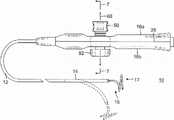
图1是本发明的导管的一个实施例的俯视平面图。Figure 1 is a top plan view of one embodiment of the catheter of the present invention.
图2A是沿第一直径截取的导管主体和中间节段的接合部的实施例的侧面剖视图。2A is a side cross-sectional view of an embodiment of a junction of a catheter body and an intermediate section taken along a first diameter.
图2B是沿大致垂直于第一直径的第二直径截取的图2A的接合部的实施例的侧面剖视图。2B is a side cross-sectional view of the embodiment of the joint of FIG. 2A taken along a second diameter that is generally perpendicular to the first diameter.
图3是图2A和2B的中间节段的端部剖视图。Figure 3 is an end cross-sectional view of the intermediate section of Figures 2A and 2B.
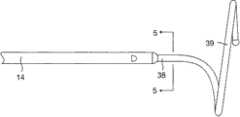
图4是远端组件的实施例的侧视图。4 is a side view of an embodiment of a distal assembly.
图5是沿线5-5截取的图4的远端组件的大致直的近端部分的端部剖视图。5 is an end cross-sectional view of the generally straight proximal portion of the distal assembly of FIG. 4 taken along line 5-5.
图6是图1的控制手柄的透视图,其示出了轴向对齐但是彼此旋转独立的第一致动组件和第二致动组件。6 is a perspective view of the control handle of FIG. 1 showing first and second actuation assemblies axially aligned but rotationally independent of each other.
图7A是沿线7-7截取的具有接合离合器机构的图1的控制手柄的端部剖视图。7A is an end cross-sectional view of the control handle of FIG. 1 with an engaged clutch mechanism, taken along line 7-7.
图7B是具有脱离的离合器机构的图7A的控制手柄的端部剖视图。7B is an end cross-sectional view of the control handle of FIG. 7A with the clutch mechanism disengaged.
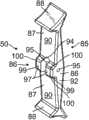
图8A是第一致动构件(例如挠曲旋钮)的实施例的侧面透视图。8A is a side perspective view of an embodiment of a first actuation member, such as a flex knob.
图8B是图8A的挠曲旋钮的另一个侧面透视图。8B is another side perspective view of the flex knob of FIG. 8A.
图9A是滑轮臂的实施例的顶部透视图。Figure 9A is a top perspective view of an embodiment of a pulley arm.
图9B是图9A的滑轮臂的端部透视图。9B is an end perspective view of the pulley arm of FIG. 9A.
图10是凸轮致动轴的实施例的侧面透视图。Figure 10 is a side perspective view of an embodiment of a cam actuated shaft.
图11A是离合器壳体的实施例的侧面透视图。11A is a side perspective view of an embodiment of a clutch housing.
图11B是图11A的离合器壳体的另一个侧面透视图。11B is another side perspective view of the clutch housing of FIG. 11A.
图12是压缩载荷垫圈的实施例的侧面透视图。12 is a side perspective view of an embodiment of a compression load washer.
图13是轴向推力轴承的实施例的侧面透视图。Figure 13 is a side perspective view of an embodiment of an axial thrust bearing.
图14是径向轴承的实施例的侧面透视图。14 is a side perspective view of an embodiment of a radial bearing.
图15是滑轮的实施例的侧面透视图。Figure 15 is a side perspective view of an embodiment of a pulley.
图16是套筒轴承的实施例的侧面透视图。Figure 16 is a side perspective view of an embodiment of a sleeve bearing.
图17A-17C是处于中立构型、右挠曲构型和左挠曲构型的控制手柄的实施例的示意图。17A-17C are schematic illustrations of embodiments of a control handle in a neutral configuration, a right deflected configuration, and a left deflected configuration.
图18A是具有外表面的径向轴承的实施例的侧面透视图,外表面形成有旋转轨道。18A is a side perspective view of an embodiment of a radial bearing having an outer surface forming a track of rotation.
图18B是图18A的径向轴承的内表面的侧面透视图。18B is a side perspective view of the inner surface of the radial bearing of FIG. 18A.
图19是局部花键轴的替代实施例的侧面透视图。Figure 19 is a side perspective view of an alternate embodiment of a partially splined shaft.
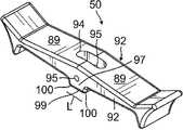
图20是第二致动构件(例如收缩线转盘)的实施例的侧面透视图。20 is a side perspective view of an embodiment of a second actuation member, such as a shrink wire dial.
具体实施方式Detailed ways
本发明涉及与医疗装置结合使用的控制手柄10,该控制手柄具有至少两个可拉伸牵拉构件,例如牵拉线等以用于启动医疗装置的部件的至少两种独立的运动或者操纵。控制手柄可与多种医疗装置中的任一种结合使用,例如被构造成用于标测和/或消融组织包括心脏的电生理(EP)导管10,其实施例如图1所示。有利的是,第一致动器用于操纵医疗装置的一个结构并且第二致动器用于操纵医疗装置的另一个结构。The present invention relates to a
图1所示的导管10包括细长导管主体12、位于导管主体12远端处的可挠曲的中间节段14、以及位于中间节段14远端处的末端节段15,所述末端节段包括具有例如螺旋形式的远端组件17。在图1和图6所示的实施例中,与导管结合使用的控制手柄16具有第一致动器,例如双向挠曲旋钮50,所述第一致动器能够启动至少一条牵拉线(如果不是一对牵拉线的话),该牵拉线从控制手柄16延伸并穿过导管主体12和中间节段14以用于中间节段的单向挠曲或双向挠曲。根据本发明的特征,控制手柄具有与第一致动器50相对的第二致动器,例如转盘52,以用于启动另一条(或第三条)牵拉线,该牵拉线用于独立地操纵或调节从中间节段14延伸的远端组件17,以例如收缩远端组件的螺旋形式。每个致动器均能够被单独地和独立地操作,而不会影响其它的致动器或者其牵拉线。The
参见图2A和2B,导管主体12包括单个中央或轴向管腔18。导管主体12具柔性,即可弯曲,但沿其长度基本上不可压缩。导管主体12可具有任何合适的构造,并且可由任何合适的材料制成。在一个实施例中,导管主体12包括由聚氨酯或PEBAX制成的外壁22。外壁22包括由不锈钢等制成的嵌入式编织网,以增大导管主体12的扭转刚度,使得当旋转控制手柄16时,导管10的顶端节段将以相应的方式旋转。Referring to FIGS. 2A and 2B ,
导管主体12的外径并非关键的,但优选不大于约8弗伦奇(French)。同样,外壁22的厚度也不关键。外壁22的内表面衬有加劲管20,其可由任何合适的材料(优选聚酰亚胺)制成。加劲管20在导管主体12的近端处相对于外壁22保持固定。通过速干胶(如Super Glue.RTM)在加劲管20的远端和外壁22之间制成第一胶接接头23。其后,用较慢干燥但较强力的胶(例如聚氨酯)在加劲管20的近端和外壁22之间形成第二胶接接头25。The outer diameter of
加劲管20以及编织外壁22在最小化导管壁厚度的同时提供改善的扭转稳定性,从而最大化单管腔的直径。加劲管20的外径与外壁22的内径大约相同或比其略小。聚酰亚胺管是合适的,因为其壁可为十分薄的而仍提供十分良好的刚度。这使中央管腔18的直径最大化而不会损失强度和刚度。聚酰亚胺材料通常不用于加劲管,因为其在弯曲时有扭结的趋势。然而,已发现相对于所述导管所用的应用,与聚氨酯、PEBAX或其它类似材料的外壁22相结合时,尤其是具有不锈钢编织网时,聚酰亚胺加劲管20在弯曲时扭结的趋势基本上得到消除。
在一个实施例中,外壁22具有约0.092英寸的外径和约0.063英寸的内径,并且聚酰亚胺加劲管20具有约0.0615英寸的外径和约0.052英寸的内径。In one embodiment,
如图2A、2B和3所示,中间节段14包括管19的较短节段,该管具有多个管腔,例如第一管腔30、第二管腔31、第三管腔32和第四管腔33。管19由合适的非毒性材料制成,所述材料优选比导管主体12更具柔性。适用于管19的材料是编织聚氨酯,即具有嵌入的编织不锈钢等的网的聚氨酯。与导管主体12的外径类似,中间节段14的外径优选不大于约8弗伦奇。各管腔的尺寸并不关键。在一个实施例中,中间节段具有约7弗伦奇(0.092英寸)的外径,并且各管腔一般具有约相同的尺寸(具有约0.022英寸的直径),或选定的管腔可具有约0.036英寸的稍大直径。As shown in Figures 2A, 2B and 3, the
图2A和图2B中示出了将导管主体12连接到中间节段14的装置。中间节段14的近端包括内沉孔24,该沉孔可接纳聚酰亚胺加劲管20的外表面。中间节段14和导管主体12通过胶29等附连。The means for connecting
如图2A和2B所示,不同的部件延伸穿过导管主体12的单管腔18,例如,引线和多个牵拉线以及任何其它线材或线缆。牵拉线相对于导管主体12的纵向移动使得使用者能通过控制手柄来控制导管的不同部分。如上所述,在一个实施例中,具有用于使中间节段14挠曲的第一挠曲牵拉线和第二挠曲牵拉线42,以及用于操纵和调节末端节段15的远端组件17的第三牵拉线35。As shown in Figures 2A and 2B, various components extend through the
单管腔导管主体12可能优于多管腔主体,因为单管腔18主体可允许能在旋转导管10时更好地控制顶端。单管腔18允许从其中穿过的部件在导管主体内自由摇摆。如果这些部件局限于多个管腔内,则它们可能会在旋转手柄16时积累能量,导致导管主体12在(例如)释放手柄时具有往回旋转的趋势,或在围绕曲线弯曲时有翻转的趋势,任何一种趋势都是不期望的性能特征。A single
同样如图3中所示,一条挠曲牵拉线42延伸穿过导管主体12的中央管腔18并进入中间节段14的第二管腔31。另一根挠曲牵拉线42延伸穿过中央管腔18并进入中间节段14的第四管腔33。在此方面,管腔31、33应为偏轴的并且在直径上为彼此相对的以用于平面内的双向挠曲。本领域的普通技术人员将会理解,挠曲牵拉线42的远端通过T形锚定器(未示出)锚定至位于中间节段14远端附近的管19的壁。在中间节段14中,每根挠曲牵拉线42延伸穿过塑性(例如Teflon.RTM)护套81,所述护套可防止挠曲牵拉线42在中间节段14挠曲时切入中间节段14的管19的壁中。As also shown in FIG. 3 , a
如图2B中所示,围绕挠曲牵拉线42的压缩线圈44从导管主体12的近端延伸至中间节段14的近端。压缩线圈44由任何合适的金属(如不锈钢)制成。压缩螺旋线圈44自身紧密地缠绕,以提供柔韧性,即弯曲性,但可抗压缩。压缩线圈44的内径优选稍大于牵拉线42的直径。例如,当牵拉线42具有约0.007英寸的直径时,压缩线圈44优选具有约0.008英寸的内径。牵拉线42上的Teflon.RTM.涂层允许它们在压缩线圈44内自由滑动。压缩线圈44的外表面被柔韧的非导电护套27覆盖,以防止压缩线圈44与其它部件(例如引线和线缆等)接触。在一个实施例中,非导电护套由聚酰亚胺管制成。As shown in FIG. 2B , a
通过胶接接头51(图2B)将压缩线圈44的近端锚定在导管主体12中的加劲管20的近端处,并且通过胶接接头49(图2B)将其远端锚定在第二管腔31和第四管腔33中的中间节段14的近端附近。The proximal end of the
结合图4,远端组件17位于中间节段14的远端处。远端组件17包括大致直的近端区域38和大致环状的主区域39。近端区域38安装在中间节段14上并且主区域39携带用于标测和/或消融的多个电极。在图5的实施例中,远端组件17包括管61。形状记忆构件54和用于远端组件上所承载的电极的引线40延伸穿过管61的管腔并且进入中间节段14和导管主体12。Referring to FIG. 4 , the
在本发明所公开的实施例中,第三牵拉线或收缩牵拉线35设成能够使大致环状的主区域39收缩,由此在例如标测或消融心脏的环状或管状区域时改变或减小其直径。收缩线35具有锚定在控制手柄16中的近端,如下文进一步所述。收缩线35延伸穿过导管主体12的中央管腔18、穿过中间节段14的第三管腔32(图3)并且进入远端组件17(图5)。In the disclosed embodiment of the present invention, the third puller wire or
第三压缩线圈46围绕收缩线35位于导管主体12和中间节段轴14内(图2A)。第三压缩线圈46从导管主体12的近端延伸并延伸至中间节段14的第三管腔32的远端附近。第三压缩线圈46由任何合适的金属(例如不锈钢)制成,并且其自身紧密地缠绕以提供柔韧性,即弯曲性,但可抗压缩。第三压缩线圈46的内径优选稍大于收缩线35的直径。压缩线圈46的外表面覆盖有柔性的,例如由聚酰亚胺管制成的非导电护套68。第三压缩线圈46优选由具有正方形或矩形横截面的线材形成,这使得其可压缩性比具有圆形横截面的线材形成的压缩线圈的可压缩性差。因此,第三压缩线圈46可防止导管主体12尤其是中间节段14在操纵收缩线35以使远端组件17收缩时发生挠曲,因为其可吸收更多的压缩。A
第三压缩线圈46在其近端处通过近侧胶接接头50而锚定到导管主体12的加劲管20,并且通过远端胶接接头锚定到中间节段14。The
应该理解,遍及导管10的胶接接头可包含聚氨酯胶等。可借助于注射器等通过在管壁中产生的孔施加该胶。此类孔可例如通过可刺穿管壁的针头等形成,其中可充分加热针头以形成永久性的孔。然后可通过该孔引入该胶以芯吸于管内一个或多个部件的周围,从而在所述一个或多个部件的整个周边的周围形成胶接接头。It should be understood that the glued joints throughout
附接到远端组件17上的环电极的引线40延伸穿过中间节段14的第一管腔30(图2A)、穿过导线主体12的中央管腔18、穿过控制手柄16、并在其近端处端接在连接器(未示出)中,所述连接器连接到用于接收和显示从环电极接收到的信息的合适监测器或其它装置。引线40延伸穿过导管主体12的中央管腔18、控制手柄16和中间节段14的近端的部分被封装在保护性护套63内,该保护性护套可由任何合适的材料优选聚酰亚胺制成。The
电磁位置传感器(未示出)被安装在远端组件17中或者远端组件17的附近,例如中间节段14的远端中。传感器电缆36从传感器延伸到中间节段的管腔30内(连同电极引线40)、进入导管主体12的中央管腔18、并进入控制手柄,在所述控制手柄处端接在合适的连接器(未示出)中。An electromagnetic position sensor (not shown) is mounted in or near the
在图6和图7A所示的实施例中,控制手柄16包括自固定凸轮致动的挠曲控制组件13,该控制组件包括挠曲旋钮50,以用于通过牵拉线42对使中间节段14双向挠曲。每根牵拉线42均由任何合适的金属(例如不锈钢或镍钛诺)制成。优选的是,每根牵拉线具有低摩擦涂层,例如Teflon.RTM.等的涂层。每根牵拉线具有优选在约0.006英寸至约0.012英寸的范围内的直径。优选的是,两根牵拉线都具有相同的直径。可用扁平的牵拉线替代圆形的牵拉线。它们的横截面尺寸应使得能提供与圆形牵拉线相同的抗拉强度。In the embodiment shown in FIGS. 6 and 7A , the control handle 16 includes a self-fixating cam-actuated
作为另外一种选择,可完全地或部分地使用可拉伸纤维代替牵拉线。所述纤维可为高模量纤维材料,优选具有基本上在412-463ksi(2480-3200Mpa)范围内的极限拉伸强度,例如高分子密度聚乙烯(例如,SpectraTM或DyneemaTM)、纺成的对位芳族聚酰胺纤维聚合物(例如,KevlarTM)或熔纺的液晶聚合物纤维绳(例如,VectranTM)、或高强度陶瓷纤维(例如,NextelTM)。本文所用的术语“纤维”可与术语“多根纤维”互换使用,因为所述张力纤维可为织造或编织构造。在任何一种情况中,这些材料趋于是柔性的,当与滑轮等缠绕啮合使用时可提供合适的耐久性,以使导管尖端挠曲较大幅度。此外,它们基本上是非伸长性的,这可增加对控制手柄的操纵的响应性,并且是非磁性的,从而它们大体上显示对于MRI是透明的。该材料的低密度性使得其对x射线机器来说大体上是透明的。该材料还可以是非导电性的以避免短路。例如,VectranTM具有高强度、高耐磨性,是电绝缘体、非磁性的,是聚合物,并且在持续的负荷条件下具有低伸长率。因此,应当理解,本文所使用的术语“线”可为线、可拉伸纤维、或者包括一个或多个线区段和一个或多个可拉伸纤维区段的可拉伸构件。Alternatively, stretchable fibers may be used in whole or in part in place of puller wires. The fibers may be a high modulus fiber material, preferably having an ultimate tensile strength substantially in the range of 412-463 ksi (2480-3200 MPa), such as high molecular density polyethylene (e.g., Spectra™ or Dyneema™ ), spun Para-aramid fiber polymer (eg, KevlarTM ) or melt-spun liquid crystal polymer fiber rope (eg, VectranTM ), or high-strength ceramic fiber (eg, NextelTM ). As used herein, the term "fiber" is used interchangeably with the term "fibers," as the tension fibers may be of woven or braided construction. In either case, these materials tend to be flexible and provide suitable durability when used in winding engagement with a pulley or the like to allow relatively large deflections of the catheter tip. Furthermore, they are substantially non-stretchable, which increases responsiveness to manipulation of the control handle, and non-magnetic, such that they appear substantially transparent to MRI. The material's low density makes it largely transparent to x-ray machines. The material can also be non-conductive to avoid short circuits. For example, Vectran™ has high strength, high wear resistance, is an electrical insulator, is non-magnetic, is a polymer, and has low elongation under sustained loading conditions. Accordingly, it should be understood that the term "wire" as used herein may be a wire, a stretchable fiber, or a stretchable member comprising one or more wire segments and one or more stretchable fiber segments.
如图1中所示,控制手柄16包括大致细长的手柄壳体,该壳体能够由任何合适的刚性材料制成。壳体可为单一构造或两个相对的半部16a、16b,所述两个半部通过胶接、超声焊接或其它合适的方法接合。挠曲控制或转向组件13响应于使用者对旋钮50的操纵使中间节段14双向挠曲。转向组件相对于其部件限定大致中央旋转轴线60。轴线60大致垂直于控制手柄的纵向轴线64。As shown in FIG. 1 , the control handle 16 includes a generally elongated handle housing that can be made of any suitable rigid material. The housing may be of unitary construction or two opposing
在图示实施例中,转向组件13包括安装在手柄壳体16a外侧的第一控制旋钮50(图8A和8B)、位于控制手柄16内侧的离合器机构54、位于控制手柄16内侧的滑轮臂62(图9A和9B)以及横向延伸穿过控制手柄16的离合器致动轴58(图11),其中滑轮臂62和离合器机构54安装在轴58上。离合器机构包括摩擦盘57,该摩擦盘旋转连接到轴和离合器壳体56(图11A和11B),离合器壳体56提供引起摩擦的表面,该表面在摩擦盘和离合器壳体彼此接触时与摩擦盘产生摩擦扭矩。离合器机构还包括用于摩擦盘57的支撑垫圈59、以及压缩载荷垫圈61(图12),以使得旋钮50自固定,从而使得保持由使用者设定的挠曲,而无需使用者持续固定旋钮50。In the illustrated embodiment, the steering
根据本发明的特征,轴58能够响应于由使用者施加给旋钮50的力而运动。在本发明所公开的实施例中,旋钮50的枢转向轴施加平移运动,从而使轴脱离离合器机构,并且旋钮50的旋转向轴施加旋转运动,从而致动滑轮臂以对牵拉构件42起作用。According to a feature of the invention,
在图10所示的实施例中,离合器致动轴58具有大致圆柱形主体65,该主体具有两个端部66a、66b以及预定长度,该预定长度小于控制手柄16的宽度。如图7A中所示,随着向外延伸穿过壳体手柄半部16a中的孔70,第一端部66a由手柄壳体半部16a支撑,孔70衬有径向轴承套筒71。第一端部66a还在手柄壳体半部16a的外侧延伸穿过轴向推力轴承73(图13),在该外侧处,旋钮50安装在第一端部66a上。旋钮在与轴58大致垂直的x/z平面84(图6)中延伸,轴58沿y轴延伸。In the embodiment shown in FIG. 10 , the
在如图7A中所示的控制手柄16内侧,轴58延伸穿过离合器壳体56的中央孔68(衬有径向轴承69(图14),该轴承可以是或者可以不是离合器壳体56的单独部件)。轴的第二端部66b朝相对的壳体半部16b延伸。因此,轴58限定旋转轴线60,该旋转轴线与控制手柄的纵向轴线64垂直。Inside the control handle 16 as shown in FIG. 7A, the
如图10的实施例中所示,旋钮50安装在其上的轴58的第一端部66a具有两个外凹口部分,形成具有两个相对的平坦表面76的较薄的交叉部分75。用于通过枢轴销78安装旋钮的第一通孔77沿横向于两个平坦表面76之间的轴主体65的长度的较薄的交叉部分75延伸(图6)。第一通孔77具有细长或椭圆形的横截面,该横截面具有沿轴主体65纵向延伸的较长的尺寸。与第一通孔77连通的局部孔79在第一通孔77与轴主体的相邻的端面81之间纵向延伸。局部孔79接纳调节定位螺钉81(图6),以用于调节枢轴销78在孔77中的位置。支撑垫圈59(例如,钎焊垫圈)固定至轴主体65,使得其轴向和旋转固定至轴。通过粘合剂等固定至垫圈59的摩擦盘57也轴向和旋转固定至轴58。摩擦盘57能够由任何引起摩擦的材料制成,例如有机或半金属制剂的成型片,包括提供摩擦系数处于从大约0.45至0.55的范围内的陶瓷化合物、矿物纤维和铜纤维的基质。As shown in the embodiment of FIG. 10 , the
参见图7A,压缩载荷垫圈61,例如碟形垫圈(图12)相对于支撑盘59向外。离合器壳体56相对于摩擦盘57直接向内。在图11A和11B所示的实施例中,壳体56具有嵌段主体53,该嵌段主体所具有中央孔68,所述中央孔与面向摩擦盘57、支撑盘59和压缩载荷垫圈61的较大的环形凹槽83相连通。衬有径向轴承69的中央孔68接纳轴58,离合器壳体56安装在轴58上。然而,凹槽83大致封闭,以由于嵌段主体53沿围绕凹槽83的周边区域具有多个孔67而形成内部腔体113,该凹槽接纳螺钉紧固件74,以用于将离合器壳体56固定至控制手柄壳体16a的内表面115。凹槽83的尺寸设定成直径略微大于摩擦盘57、支撑盘59和垫圈61的大致类似的直径,以为这些部件提供间隙。凹槽83沿y轴所具有的轴向深度小于离合器壳体56的厚度但是大于这些部件的组合厚度,以便提供间隙以用于摩擦盘57在离合器脱离时在腔体113的限制下沿旋转轴线60移离与凹槽83的内表面117的接触,如下进一步解释的。Referring to FIG. 7A , a
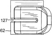
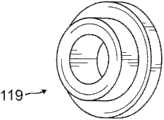
用于通过压力配合连接销83安装滑轮臂62的通孔82进一步朝向轴58(图10)的第二端部66b,压力配合连接销83将滑轮臂62轴向和旋转连接至轴主体65。径向轴承119(图16)可以衬套滑轮臂62的中央孔121。滑轮123(图15)占据横跨中央孔121彼此相对的相应通孔125。Further towards the
如图17A至17C所示,牵拉线42通过控制手柄的远端中的端口进入控制手柄16。牵拉线通过狭缝开口127(图9B)进入滑轮臂62并且每根线均在通过狭缝开口127离开滑轮臂之前围绕相应的滑轮123缠绕或旋拧约180度。每个牵拉构件42的近端均锚定在阻挡件147中,该阻挡件相对于控制手柄16固定。通过沿一个方向旋转旋钮50,滑轮臂62通过轴58沿该方向旋转,从而将牵拉构件42拉动到该侧上,以使中间节段14沿该方向挠曲。类似的滑轮臂在美国专利No.7377906中有所描述,该专利的全部公开内容以引用的方式并入本文。As shown in Figures 17A to 17C, the
根据本发明的特征,当离合器机构接合时,在摩擦盘57与离合器壳体56彼此接触时其间所产生的摩擦扭矩用于通过抵抗轴58和固定安装在其上的滑轮臂62的旋转而使得旋钮50自固定。因此,挠曲旋钮50在旋钮仍然处于平面84内的情况下围绕旋转轴线60旋转有利地被接合时的离合器机构54所抵抗。为了使离合器结构脱离,旋钮50被枢转到平面84外,如下文进一步描述的。According to a feature of the present invention, when the clutch mechanism is engaged, the frictional torque developed between the
在图8A和8B所示的实施例中,旋钮50具有细长主体85,该主体具有两个中央凸轮部分86、两个端部87,所述端部具有增大的端部88、面向外的表面89、面向内的表面90以及两个侧表面92。主体85安装在轴58的第一端部66a上的中央凸轮部分86处并且定位成与轴垂直,使得细长主体85限定平面84(图6)。增大的端部87能够使使用者通过拇指和手指操纵旋钮50,包括(1)将旋钮50枢转至“平面外”,以释放离合器结构54,以及(2)在处于“平面外”的同时径向旋转旋钮50,从而旋转滑轮臂62以用于导管的双向挠曲。In the embodiment shown in FIGS. 8A and 8B , the
旋钮50的枢转操纵涉及旋钮50的两个中央凸轮部分86。位于中央凸轮部分之间的通孔94在面向外的表面89与面向内的表面90之间延伸,该通孔接纳轴58的第一端部66a。如图6中更佳可见的,与轴58的椭圆形通孔77对齐的较小和圆形的通孔95延伸穿过旋钮50的侧面92,以用于在为旋钮50提供枢转轴线199以枢转至平面84中和平面84外的过程中接纳枢轴销78。值得注意的是,接纳轴58的第一端部66a的通孔94相对于第一端部66a基本增大,使得端部66a具有空间随着旋钮50枢转至平面84外以释放离合器机构54而在通孔94中操纵。局部轴向孔79中的定位螺钉80用于调节枢轴销78在通孔77中的横向位置,以用于调节旋钮50中枢转移动的量。Pivotal manipulation of the
如图8A中最佳可见,旋钮的每个中央凸轮部分86均形成有从面向内的表面90突出的凸轮突出部97。每个凸轮突出部97均具有长度为L的基本平坦的接触表面99以及位于平坦的接触表面99的相对侧上的两个弯曲的接触表面或“圆角”100,长度L略微大于轴58的直径。这些拐角100在其与通孔77和/或旋钮50围绕其枢转的枢轴销78的距离方面有利地与平坦的接触表面99不同。因此,旋钮50枢转至平面84外将凸轮突出部97相对于轴向推力轴承73的外表面101接合从平面表面99改变成拐角100中的任何一个。这种凸轮接合的改变使轴58相对于控制壳体轴向平移,以用于脱离离合器结构,如下文进一步详细解释的。As best seen in FIG. 8A , each
参见图7A和7B,离合器机构54包括每一个均安装在轴58上并且轴向和旋转连接到轴58的壳体56、摩擦盘57、支撑垫圈59和压缩载荷盘61。相对于壳体半部16a的内表面115产生杠杆作用的压缩载荷盘61在相对于轴58的旋转产生摩擦扭矩的过程中通过相对于离合器壳体56的凹槽83的内表面117压缩摩擦盘57来对摩擦盘57进行预载荷。因此,通过使挠曲旋钮50处于“平面中”(图7A),旋钮抵抗旋转并且有利地保持在如由使用者限定的x/z平面84内的任何径向位置处,以用于导管期望地挠曲直到离合器机构54被使用者脱离。Referring to FIGS. 7A and 7B ,
为了脱离离合器机构54,使用者通过向内按压两个增大的端部87中的任意一个上而将旋钮50枢转至平面84外(图7B)。随着旋钮50以该方式枢转,相对于轴向推力轴承73的外表面101的凸轮接合表面从凸轮突出部97的平坦表面99变成由于被使用者按下而更靠近增大的端部87的上部组或下部组的凸轮拐角100。该变化使轴向推力轴承73和枢轴96上的接合表面(图6)之间的间距由R1增加至R2,从而使枢轴销78/枢轴96向外移动并且使轴58向外平移。由于离合器机构54的摩擦盘57(以及支撑垫圈59和压缩载荷垫圈61)固定在轴58上,摩擦盘57也向外平移并且移离与离合器壳体56的凹槽表面117的摩擦接触。这样一来,离合器机构54脱离,从而使得使用者能够通过旋钮50对轴58进行自由旋转。因此,仅当旋钮50枢转至平面84外时通过脱离离合器机构而有利于旋钮50旋转。To disengage the
应当理解,轴向推力轴承可为手柄半部16a的整体部分。例如,当控制壳体由30%玻璃填充的聚碳酸酯材料构造时,控制壳体可以包括体积为大约10-15%的Teflon
由于压缩载荷垫圈61相对于控制手柄壳体半部16a受到压缩而使离合器机构54脱离,因此离合器机构受到压缩载荷垫圈61偏置从而重新接合。也就是说,一旦使用者释放旋钮50的枢转,压缩载荷垫圈61就弹回至其初始形状,由此使轴58自动向内平移并且将摩擦盘57推回至与凹槽表面117摩擦接触。当凸轮接合表面与轴向推力轴承73回到平坦表面99时,该平移将旋钮50拉回至平面84(图7A)中。再一次,离合器机构54被接合并且旋钮50抵抗旋转。As the
由于可围绕其滑轮123经历每根挠曲牵拉线42的重复循环弯曲,因此控制手柄内(特别是围绕滑轮的)的每根牵拉线的区段可以包括可更好地经受应力和张力的可拉伸纤维区段,例如上文所述的可拉伸纤维区段。为此目的,卷曲的连接器129(图17A-17C)被设成将每个第一牵拉线区段和第二牵拉线区段的近端42D连接至相应的近端可拉伸纤维区段42P的远端。Because of the repeated cyclic bending that each flexing
结合图6和图7A,大致容纳在其它外壳体半部16b中的第二牵拉线致动组件110包括具有部分外花键的轴112、通过与外花键联锁的内花键旋转连接到轴112的正齿轮114、响应于轴112的旋转的平移构件116、压缩载荷垫圈118以及致动转盘52。应当理解,正齿轮114能够形成为正齿轮形成部,所述正齿轮形成部与花键轴112整体形成为单个部件,如图19所示。正齿轮-轴组合可以是单件注射成型设计以降低制造成本。轴和齿轮可以由注射成型的粉末金属制成或者轴可为金属(例如,黄铜合金260或不锈钢)并且塑性正齿轮可被衬套成型到金属轴上。轴112具有纵向孔120。在内端处,孔接纳第一致动组件13的离合器致动轴58的第二端部66b。第二端部66b的尺寸设定成直径相对于孔120略小,使得轴58和112能够独立于彼此旋转并且第二端部66b能够根据需要平移离开轴112。因此,尽管轴向对齐,但是第一致动组件的轴58与第二致动组件的轴112之间不具有严格的旋转连接。6 and 7A, a second puller
在本发明所公开的实施例中,平移构件是设置在正齿轮114(或者可在本文中互换使用的正齿轮形成部)下方的齿条116,齿条116与正齿轮114相接合,使得正齿轮114的旋转沿控制手柄16的纵向方向64向齿条116施加平移运动(箭头131)。齿条116定位在升高的脊或轨道122上,所述脊或轨道形成在控制手柄壳体半部16b的内表面124中。轨道122沿纵向方向引导齿条116的运动。应当理解,转盘52沿一个方向的旋转导致齿条向远端平移,并且沿相反方向的旋转导致齿条向近端平移。第三牵拉构件35的近端锚定在齿条116中,使得齿条的平移运动在操纵导管的另一个结构的过程中,例如在拉紧远端组件的螺旋形式的过程中致动第三牵拉构件。In the disclosed embodiment of the invention, the translating member is a
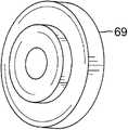
如图7A中最佳示出的,致动转盘52安装在轴112的外端130上,轴112延伸穿过控制手柄壳体半部16b中的通孔132。通孔132衬有径向轴承119(图18A和18B),该径向轴承能够整体成型为壳体半部16b的一部分。在这方面,壳体半部中的任意一个或两个能够由具有玻璃纤维(例如,体积为大约30%的玻璃纤维)的塑性材料构造,以使在各个垫圈受到压缩的长期载荷条件下发生永久性变形的风险最小化。轴承119可以是烧结的金属套筒轴承,以防止手柄壳体在长期压缩载荷的情况下发生永久性变形或“蠕变”。As best shown in FIG. 7A, the
在图20所示的实施例中,致动转盘52具有盘形形状,该盘形形状具有圆形横截面。轴112的外端130容纳在致动转盘52中的中央局部孔136中。两个相对的径向横向通孔150与转盘52的中央局部孔136连通。定位螺钉152被插入在每个孔150中以用于在旋转地连接转盘52与轴112时与轴112摩擦接触。与轴112平行的偏心通孔156在致动转盘52中形成。孔156与C形凹槽160连通,该凹槽形成在轴承119的面向外的表面143中(图18A)。压力配合销162插入孔156中,该销的端部被接纳在凹槽160中并且骑压在凹槽160中。在设定第三牵拉线35的最大行进和最小行进以用于调节远端组件17时,凹槽的端部164用作限制转盘52的旋转运动程度的销162的阻挡件。应当理解,凹槽160可整体成型为控制手柄壳体半部16b的一部分。In the embodiment shown in Figure 20, the
第二锁定顶盖螺钉168将转盘52固定到第二轴112。顶盖螺钉168还提供增量摩擦调节装置,以通过允许调节轴112上的部件,尤其是压缩载荷垫圈118的轴向压缩来使得转盘52自固定。螺钉168与较大的孔136连通并且轴向对齐地被接纳在转盘52的中央孔138中。螺钉168通过其中的孔120与轴112相接合。安装在轴112上的保持环170(图7A)相对于正齿轮114固定轴112。保持环170将第二组件保持固定,并且还相对于轴承119对压缩垫圈118进行预载荷,以使得转盘52自固定。A second
在使用时,将合适的引导护套插入患者体内,其远端被定位在期望的位置。可与本发明一起使用的合适的引导护套的例子为Preface.TM BraidingGuiding Sheath,其可从Biosense Webster,Inc.(Diamond Bar,Calif.)商购获得。将该护套的远端引导进入腔室(例如心房)中的一个内。将根据本发明的实施例的导管经引导护套送入,直至其远端从引导护套的远端延伸出来。当导管经引导护套被送入时,远端组件17被伸直以适于穿过该护套。一旦导管的远端被定位在所需位置时,将引导护套朝近侧牵拉,使得可挠曲的中间节段14和远端组件17延伸出该护套的外面,并且远端组件17由于其形状记忆而恢复到其初始形状。In use, a suitable introducer sheath is inserted into the patient with its distal end positioned at the desired location. An example of a suitable guiding sheath that can be used with the present invention is Preface.™ Braiding Guiding Sheath, which is commercially available from Biosense Webster, Inc. (Diamond Bar, Calif.). The distal end of the sheath is guided into one of the chambers (eg, atrium). A catheter according to an embodiment of the present invention is advanced through the guide sheath until its distal end extends out from the distal end of the guide sheath. As the catheter is advanced through the introducing sheath, the
挠曲旋钮50处于“平面中”,离合器机构被接合使得挠曲旋钮50抵抗旋转。然而,通过将挠曲旋钮50枢转至处于“平面外”,使用者使离合器机构54脱离,使得旋钮50能够旋转以致动滑轮臂62从而用于挠曲中间节段14。朝一个方向转动挠曲臂50可使中间节段14朝该方向挠曲。朝相对的方向转动挠曲转盘50可使中间节段14朝该相对方向挠曲。当已经实现期望挠曲时,使用者释放旋钮50,旋钮50易于通过离合器机构重新接合以使旋钮自固定而返回“平面中”。The
使用者可以接着通过沿一个方向旋转转盘52以拉紧和减小大体圆形的主区域,或者沿相反方向旋转转盘52以放松和增大来调节所述远端组件17的大致环形的主区域39。通过操纵转盘52,调节大致环状的39以适合肺静脉或其它管状结构。在本发明所公开的实施例中,通过沿一个方向旋转转盘,收缩线35被沿近侧拉动以拉紧和减小大致环形的区域39的直径,并且通过沿其它方向旋转转盘,第三牵拉线或收缩线35被放松以将大致环形的区域39释放至其初始直径。大致环形的主要区域的周边与管状区域内部的周边接触,接触范围优选地为主要区域周边的至少约50%,更优选地为至少约70%,还更优选地为至少80%。当已经实现期望的周长时,使用者释放也是自固定的转盘52。大致环状部分39上的电极的环状布置方式使得能够测量管状结构的周围的电活动,以使得可确定电极之间的异位搏动。因为大致环状的主区域39的直径大致对应于肺静脉或其他管状结构的直径,所以该环状主区域的尺寸允许测量沿肺静脉或心脏的或心脏附近的其它管状结构的直径的电活动。由于轴58和112未旋转连接,因此每个轴均能够独立于彼此旋转,并且因此每个致动组件都能够独立于彼此起作用。The user may then adjust the generally annular main area of the
已结合本发明的当前优选实施例进行了以上描述。本发明所属技术领域内的技术人员将会知道,在不有意背离本发明的原则、精神和范围的前提下,可对所述结构作出更改和修改。例如,可改进该导管以使得第三牵拉线推进和回缩另一部件(例如导引线或针头)。本领域中的普通技术人员应了解,附图未必按比例绘制。因此,以上描述不应视为仅与所描述和图示的精确结构有关,而应视为符合以下具有最全面和合理范围的权利要求书,并作为权利要求书的支持。The foregoing description has been presented in conjunction with presently preferred embodiments of the invention. Those skilled in the art to which this invention pertains will appreciate that changes and modifications may be made in the structures described without intentionally departing from the principle, spirit and scope of this invention. For example, the catheter can be modified so that a third puller wire advances and retracts another component (eg, a guide wire or needle). Those of ordinary skill in the art will appreciate that the drawings are not necessarily drawn to scale. Accordingly, the above description should not be read as pertaining only to the precise structures described and illustrated, but should be read in accordance with, and as support for, the following claims in their fullest and reasonable scope.
Claims (20)
Translated fromChineseApplications Claiming Priority (3)
| Application Number | Priority Date | Filing Date | Title |
|---|---|---|---|
| US13/327,448US9101269B2 (en) | 2011-12-15 | 2011-12-15 | Self-holding medical device control handle with cam actuated clutch mechanism |
| US13/327448 | 2011-12-15 | ||
| US13/327,448 | 2011-12-15 |
Publications (2)
| Publication Number | Publication Date |
|---|---|
| CN103156686Atrue CN103156686A (en) | 2013-06-19 |
| CN103156686B CN103156686B (en) | 2016-08-31 |
Family
ID=47631184
Family Applications (1)
| Application Number | Title | Priority Date | Filing Date |
|---|---|---|---|
| CN201210545425.1AActiveCN103156686B (en) | 2011-12-15 | 2012-12-14 | There is the self-retaining medical device control handle of cam-actuated clutch mechanism |
Country Status (7)
| Country | Link |
|---|---|
| US (3) | US9101269B2 (en) |
| EP (1) | EP2604174B8 (en) |
| JP (1) | JP6133049B2 (en) |
| CN (1) | CN103156686B (en) |
| AU (1) | AU2012261571B2 (en) |
| CA (1) | CA2798786C (en) |
| RU (1) | RU2608440C2 (en) |
Cited By (17)
| Publication number | Priority date | Publication date | Assignee | Title |
|---|---|---|---|---|
| CN104546115A (en)* | 2013-10-15 | 2015-04-29 | 沁成垠 | Direction-adjustable electrode catheter assembly |
| CN106137380A (en)* | 2015-03-30 | 2016-11-23 | 上海微创电生理医疗科技有限公司 | A kind of modular catheter and use the radio frequency ablation catheter of this handle |
| CN106491190A (en)* | 2016-12-04 | 2017-03-15 | 李长慧 | The convenient ovarian tumor perforator for adjusting angle |
| CN107613837A (en)* | 2015-06-02 | 2018-01-19 | 武汉佑康科技有限公司 | Self-locking angle-adjusting mechanism for endoscope |
| CN108020120A (en)* | 2016-11-02 | 2018-05-11 | 贝尔雷斯公司 | Optical devices knob with variable rotational resistance |
| CN108159549A (en)* | 2016-12-07 | 2018-06-15 | 韦伯斯特生物官能(以色列)有限公司 | With rack-and-pinion flexure mechanism can control type guide sheath |
| CN108371534A (en)* | 2018-01-24 | 2018-08-07 | 深圳市斯玛仪器有限公司 | A kind of endoscope guiding device and a kind of medical instrument |
| CN109414156A (en)* | 2016-07-01 | 2019-03-01 | 布里奥设备有限责任公司 | Intubation stylet with video feed |
| CN110769889A (en)* | 2017-08-02 | 2020-02-07 | 住友电木株式会社 | medical equipment |
| CN114343822A (en)* | 2021-12-16 | 2022-04-15 | 上海玮启医疗器械有限公司 | Variable-resistance ablation control handle and ablation catheter |
| CN114423481A (en)* | 2019-09-20 | 2022-04-29 | 伯恩森斯韦伯斯特(以色列)有限责任公司 | Catheter instrument with three pull wires |
| CN114711953A (en)* | 2022-04-29 | 2022-07-08 | 江苏唯德康医疗科技有限公司 | Endoscopic surgical instrument |
| CN114786759A (en)* | 2019-12-12 | 2022-07-22 | 国立大学法人滋贺医科大学 | Deflection operation device for medical equipment |
| CN115444620A (en)* | 2017-09-19 | 2022-12-09 | 爱德华兹生命科学公司 | Multi-directional steerable handle for catheter manipulation |
| CN115474988A (en)* | 2022-09-05 | 2022-12-16 | 苏州心锐医疗科技有限公司 | Handle position driving structure for multi-degree-of-freedom surgical operation instrument |
| US11571549B2 (en) | 2017-08-02 | 2023-02-07 | Sumitomo Bakelite Co., Ltd. | Medical device |
| CN116710168A (en)* | 2020-11-24 | 2023-09-05 | 波士顿科学国际有限公司 | Clutch system for flexible endoscope |
Families Citing this family (42)
| Publication number | Priority date | Publication date | Assignee | Title |
|---|---|---|---|---|
| US10232150B2 (en) | 2010-03-11 | 2019-03-19 | Merit Medical Systems, Inc. | Body cavity drainage devices and related methods |
| US9101269B2 (en)* | 2011-12-15 | 2015-08-11 | Biosense Webster (Israel), Ltd. | Self-holding medical device control handle with cam actuated clutch mechanism |
| US9050010B2 (en)* | 2012-12-31 | 2015-06-09 | Biosense Webster (Israel) Ltd. | Double loop lasso with single puller wire for bi-directional actuation |
| US9174023B2 (en)* | 2013-01-07 | 2015-11-03 | Biosense Webster (Israel) Ltd. | Unidirectional catheter control handle with tensioning control |
| US20140200639A1 (en) | 2013-01-16 | 2014-07-17 | Advanced Neuromodulation Systems, Inc. | Self-expanding neurostimulation leads having broad multi-electrode arrays |
| WO2014182855A1 (en)* | 2013-05-07 | 2014-11-13 | St. Jude Medical, Atrial Fibrillation Division, Inc. | Steering actuator for deflectable catheter |
| KR102160753B1 (en)* | 2013-09-13 | 2020-09-28 | 삼성전자주식회사 | Endoscope device |
| JP2015128535A (en)* | 2014-01-08 | 2015-07-16 | 国立大学法人九州大学 | Sheath for bending instruments |
| JP6563940B2 (en)* | 2014-02-06 | 2019-08-21 | ノバルティス アーゲー | Manufacture of articulating ophthalmic surgical probes |
| US10029036B2 (en) | 2014-06-27 | 2018-07-24 | Merit Medical Systems, Inc. | Placement tools for body cavity drainage devices and related methods |
| US9821097B2 (en)* | 2014-06-27 | 2017-11-21 | Merit Medical Systems, Inc. | Body cavity drainage devices including drainage tubes having inline portions and related methods |
| US9604033B2 (en) | 2014-06-27 | 2017-03-28 | Harrison M. Lazarus | Body cavity drainage devices with locking devices and related methods |
| US9649415B2 (en) | 2014-06-27 | 2017-05-16 | Harrison M. Lazarus | Surgical kits for body cavity drainage and related methods |
| US10576249B2 (en)* | 2014-09-30 | 2020-03-03 | St. Jude Medical Cardiology Division, Inc. | Medical device including an actuator restraining assembly |
| US9801585B2 (en) | 2014-12-31 | 2017-10-31 | Biosense Webster (Israel) Ltd. | Electrocardiogram noise reduction |
| WO2016111042A1 (en)* | 2015-01-09 | 2016-07-14 | オリンパス株式会社 | Endoscope operation mechanism and endoscope |
| CN107205774B (en) | 2015-01-28 | 2020-05-29 | 圣犹达医疗用品心脏病学部门有限公司 | Thermal mapping catheter |
| US9993648B2 (en)* | 2015-03-27 | 2018-06-12 | Medtronic, Inc. | Medical device delivery system |
| WO2016166827A1 (en)* | 2015-04-15 | 2016-10-20 | 国立大学法人九州大学 | Sheath for bendable treatment tool and bendable treatment tool having said sheath incorporated therein |
| US10492857B2 (en) | 2015-08-06 | 2019-12-03 | Boston Scientific Scimed Inc | Deployment control apparatus for a catheter with a deployable array |
| US9931487B2 (en) | 2015-08-06 | 2018-04-03 | Boston Scientific Scimed, Inc. | Bidirectional steering control apparatus for a catheter |
| JP7074666B2 (en) | 2015-11-25 | 2022-05-24 | メリット・メディカル・システムズ・インコーポレイテッド | Maneuverable sheath catheter and how to use |
| CN109069799B (en)* | 2016-04-08 | 2021-07-16 | 圣犹达医疗用品心脏病学部门有限公司 | Adjustable ring catheter handle for mapping |
| WO2018060411A1 (en)* | 2016-09-30 | 2018-04-05 | Koninklijke Philips N.V. | Control handle for steerable medical devices |
| WO2018098465A1 (en)* | 2016-11-28 | 2018-05-31 | Inventio, Inc. | Endoscope with separable, disposable shaft |
| US10907626B2 (en) | 2017-02-16 | 2021-02-02 | Biosense Webster (Israel) Ltd. | Peristaltic pump with reduced triboelectric effects |
| FR3073387B1 (en) | 2017-11-13 | 2025-09-05 | Lso Medical | ENDOVEINOUS TREATMENT ASSEMBLY AND DEVICE |
| US11517715B2 (en)* | 2018-01-02 | 2022-12-06 | Biosense Webster (Israel) Ltd. | Deflectable medical probe |
| US11559662B2 (en) | 2018-04-13 | 2023-01-24 | Merit Medical Systems, Inc. | Steerable drainage devices |
| EP3768185B1 (en) | 2018-05-21 | 2023-06-14 | St. Jude Medical, Cardiology Division, Inc. | Radio-frequency ablation and direct current electroporation catheters |
| JP7049478B2 (en)* | 2018-10-01 | 2022-04-06 | オリンパス株式会社 | Fixing mechanism for curved operation knob and endoscope |
| US10646104B1 (en)* | 2018-10-29 | 2020-05-12 | G.I. View Ltd. | Disposable endoscope |
| US11698059B2 (en) | 2018-12-29 | 2023-07-11 | Biosense Webster (Israel) Ltd. | Disposable dual-action reciprocating pump assembly |
| US11795941B2 (en) | 2018-12-29 | 2023-10-24 | Biosense Webster (Israel) Ltd. | Using silicone o-rings in dual action irrigation pump |
| US11964114B2 (en)* | 2020-05-22 | 2024-04-23 | Acclarent, Inc. | Shaft deflection control assembly for ENT guide instrument |
| JP2023529459A (en)* | 2020-06-11 | 2023-07-10 | ボストン サイエンティフィック リミテッド | MEDICAL SYSTEMS, DEVICES AND RELATED METHODS |
| WO2022009094A1 (en)* | 2020-07-08 | 2022-01-13 | Baylis Medical Company Inc. | Steerable medical device, handle for a medical device, and method for operating a medical device |
| WO2022038546A1 (en) | 2020-08-18 | 2022-02-24 | St. Jude Medical, Cardiology Division, Inc. | High-density electrode catheters with magnetic position tracking |
| JP2024519830A (en) | 2021-05-19 | 2024-05-21 | ボストン サイエンティフィック サイムド,インコーポレイテッド | Medical Devices and Related Methods |
| US11986148B2 (en)* | 2021-08-04 | 2024-05-21 | GE Precision Healthcare LLC | Ergonomic control handle for interventional imaging probe |
| US20240091502A1 (en)* | 2022-09-20 | 2024-03-21 | Biosense Webster (Israel) Ltd. | Catheter shaft with multi-plane articulation and rotation |
| IL319540A (en)* | 2022-09-21 | 2025-05-01 | Kusmo Inc | Catheter stabilizer and grip |
Citations (6)
| Publication number | Priority date | Publication date | Assignee | Title |
|---|---|---|---|---|
| US20020161330A1 (en)* | 2001-04-30 | 2002-10-31 | Frank Nguyen | Asymmetrical bidirectional steerable catheter |
| US20050272975A1 (en)* | 2004-03-23 | 2005-12-08 | Mcweeney John O | In-vivo visualization system |
| US20050288656A1 (en)* | 2004-06-24 | 2005-12-29 | Koerner Richard J | System for bi-directionally controlling the cryo-tip of a cryoablation catheter |
| US20060270976A1 (en)* | 2005-05-31 | 2006-11-30 | Prorhythm, Inc. | Steerable catheter |
| US20100004633A1 (en)* | 2008-07-07 | 2010-01-07 | Voyage Medical, Inc. | Catheter control systems |
| CN102232869A (en)* | 2010-04-26 | 2011-11-09 | 韦伯斯特生物官能公司 | Irrigated catheter with internal position sensor |
Family Cites Families (18)
| Publication number | Priority date | Publication date | Assignee | Title |
|---|---|---|---|---|
| US4960134A (en) | 1988-11-18 | 1990-10-02 | Webster Wilton W Jr | Steerable catheter |
| RU2033108C1 (en)* | 1989-04-18 | 1995-04-20 | Александр Вадимович Никонов | Device for catheterization of vessels |
| US5195968A (en)* | 1990-02-02 | 1993-03-23 | Ingemar Lundquist | Catheter steering mechanism |
| US5891088A (en) | 1990-02-02 | 1999-04-06 | Ep Technologies, Inc. | Catheter steering assembly providing asymmetric left and right curve configurations |
| US5628775A (en)* | 1991-11-08 | 1997-05-13 | Ep Technologies, Inc. | Flexible bond for sleeves enclosing a bendable electrode tip assembly |
| JP3526598B2 (en)* | 1992-12-04 | 2004-05-17 | シー・アール・バード・インコーポレーテッド | Catheter and independent handle / actuator for independent proximal and distal control |
| US6656111B2 (en)* | 2000-04-19 | 2003-12-02 | Pentax Corporation | Control device for an endoscope |
| US6579278B1 (en) | 2000-05-05 | 2003-06-17 | Scimed Life Systems, Inc. | Bi-directional steerable catheter with asymmetric fulcrum |
| US6511471B2 (en) | 2000-12-22 | 2003-01-28 | Biocardia, Inc. | Drug delivery catheters that attach to tissue and methods for their use |
| US6652506B2 (en)* | 2001-05-04 | 2003-11-25 | Cardiac Pacemakers, Inc. | Self-locking handle for steering a single or multiple-profile catheter |
| US6648875B2 (en) | 2001-05-04 | 2003-11-18 | Cardiac Pacemakers, Inc. | Means for maintaining tension on a steering tendon in a steerable catheter |
| US7758625B2 (en)* | 2003-09-12 | 2010-07-20 | Abbott Vascular Solutions Inc. | Delivery system for medical devices |
| US7377906B2 (en) | 2004-06-15 | 2008-05-27 | Biosense Webster, Inc. | Steering mechanism for bi-directional catheter |
| US9833595B2 (en)* | 2005-12-30 | 2017-12-05 | Biosense Webster, Inc. | Dual-lever bi-directional handle |
| US8118775B2 (en) | 2008-09-09 | 2012-02-21 | Biosense Webster, Inc. | Deflectable catheter with bonded center strut and method of manufacture for same |
| US9033916B2 (en)* | 2009-08-28 | 2015-05-19 | Biosense Webster, Inc. | Catheter with multi-functional control handle having rotational mechanism |
| CN102858223B (en) | 2010-04-28 | 2015-04-29 | 奥林巴斯医疗株式会社 | Operating Mechanism, Endoscopic Device and Guiding Catheter |
| US9101269B2 (en)* | 2011-12-15 | 2015-08-11 | Biosense Webster (Israel), Ltd. | Self-holding medical device control handle with cam actuated clutch mechanism |
- 2011
- 2011-12-15USUS13/327,448patent/US9101269B2/enactiveActive
- 2012
- 2012-12-07AUAU2012261571Apatent/AU2012261571B2/ennot_activeCeased
- 2012-12-13CACA2798786Apatent/CA2798786C/ennot_activeExpired - Fee Related
- 2012-12-14EPEP12197175.8Apatent/EP2604174B8/enactiveActive
- 2012-12-14JPJP2012273239Apatent/JP6133049B2/enactiveActive
- 2012-12-14CNCN201210545425.1Apatent/CN103156686B/enactiveActive
- 2012-12-14RURU2012154286Apatent/RU2608440C2/enactive
- 2015
- 2015-08-05USUS14/819,353patent/US10293138B2/enactiveActive
- 2019
- 2019-05-17USUS16/415,207patent/US11491311B2/enactiveActive
Patent Citations (6)
| Publication number | Priority date | Publication date | Assignee | Title |
|---|---|---|---|---|
| US20020161330A1 (en)* | 2001-04-30 | 2002-10-31 | Frank Nguyen | Asymmetrical bidirectional steerable catheter |
| US20050272975A1 (en)* | 2004-03-23 | 2005-12-08 | Mcweeney John O | In-vivo visualization system |
| US20050288656A1 (en)* | 2004-06-24 | 2005-12-29 | Koerner Richard J | System for bi-directionally controlling the cryo-tip of a cryoablation catheter |
| US20060270976A1 (en)* | 2005-05-31 | 2006-11-30 | Prorhythm, Inc. | Steerable catheter |
| US20100004633A1 (en)* | 2008-07-07 | 2010-01-07 | Voyage Medical, Inc. | Catheter control systems |
| CN102232869A (en)* | 2010-04-26 | 2011-11-09 | 韦伯斯特生物官能公司 | Irrigated catheter with internal position sensor |
Cited By (27)
| Publication number | Priority date | Publication date | Assignee | Title |
|---|---|---|---|---|
| CN104546115B (en)* | 2013-10-15 | 2017-01-04 | 沁成垠 | Direction regulation electrode catheter assembly |
| CN104546115A (en)* | 2013-10-15 | 2015-04-29 | 沁成垠 | Direction-adjustable electrode catheter assembly |
| CN106137380A (en)* | 2015-03-30 | 2016-11-23 | 上海微创电生理医疗科技有限公司 | A kind of modular catheter and use the radio frequency ablation catheter of this handle |
| CN106137380B (en)* | 2015-03-30 | 2019-03-08 | 上海微创电生理医疗科技有限公司 | A kind of modular catheter and the radio frequency ablation catheter using the handle |
| CN107613837A (en)* | 2015-06-02 | 2018-01-19 | 武汉佑康科技有限公司 | Self-locking angle-adjusting mechanism for endoscope |
| CN109414156A (en)* | 2016-07-01 | 2019-03-01 | 布里奥设备有限责任公司 | Intubation stylet with video feed |
| CN108020120A (en)* | 2016-11-02 | 2018-05-11 | 贝尔雷斯公司 | Optical devices knob with variable rotational resistance |
| CN108020120B (en)* | 2016-11-02 | 2021-11-26 | 贝尔雷斯公司 | Optical device knob with variable rotational resistance |
| CN106491190B (en)* | 2016-12-04 | 2019-09-24 | 李长慧 | Facilitate the ovarian neoplasm puncture outfit for adjusting angle |
| CN106491190A (en)* | 2016-12-04 | 2017-03-15 | 李长慧 | The convenient ovarian tumor perforator for adjusting angle |
| CN108159549A (en)* | 2016-12-07 | 2018-06-15 | 韦伯斯特生物官能(以色列)有限公司 | With rack-and-pinion flexure mechanism can control type guide sheath |
| CN108159549B (en)* | 2016-12-07 | 2022-05-31 | 韦伯斯特生物官能(以色列)有限公司 | Steerable guide sheath with rack and pinion flexure mechanism |
| US11577050B2 (en) | 2017-08-02 | 2023-02-14 | Sumitomo Bakelite Co., Ltd. | Medical device |
| US11571549B2 (en) | 2017-08-02 | 2023-02-07 | Sumitomo Bakelite Co., Ltd. | Medical device |
| CN110769889A (en)* | 2017-08-02 | 2020-02-07 | 住友电木株式会社 | medical equipment |
| CN115444620A (en)* | 2017-09-19 | 2022-12-09 | 爱德华兹生命科学公司 | Multi-directional steerable handle for catheter manipulation |
| CN108371534A (en)* | 2018-01-24 | 2018-08-07 | 深圳市斯玛仪器有限公司 | A kind of endoscope guiding device and a kind of medical instrument |
| CN114423481A (en)* | 2019-09-20 | 2022-04-29 | 伯恩森斯韦伯斯特(以色列)有限责任公司 | Catheter instrument with three pull wires |
| CN114423481B (en)* | 2019-09-20 | 2024-10-18 | 伯恩森斯韦伯斯特(以色列)有限责任公司 | Catheter device with three puller wires |
| CN114786759A (en)* | 2019-12-12 | 2022-07-22 | 国立大学法人滋贺医科大学 | Deflection operation device for medical equipment |
| CN116710168A (en)* | 2020-11-24 | 2023-09-05 | 波士顿科学国际有限公司 | Clutch system for flexible endoscope |
| CN114343822B (en)* | 2021-12-16 | 2022-09-30 | 上海玮启医疗器械有限公司 | Variable-resistance ablation control handle and ablation catheter |
| CN114343822A (en)* | 2021-12-16 | 2022-04-15 | 上海玮启医疗器械有限公司 | Variable-resistance ablation control handle and ablation catheter |
| CN114711953A (en)* | 2022-04-29 | 2022-07-08 | 江苏唯德康医疗科技有限公司 | Endoscopic surgical instrument |
| CN114711953B (en)* | 2022-04-29 | 2023-03-10 | 江苏唯德康医疗科技有限公司 | Endoscopic surgical instrument |
| CN115474988A (en)* | 2022-09-05 | 2022-12-16 | 苏州心锐医疗科技有限公司 | Handle position driving structure for multi-degree-of-freedom surgical operation instrument |
| CN115474988B (en)* | 2022-09-05 | 2024-09-24 | 苏州心锐医疗科技有限公司 | Handle part driving structure for multi-degree-of-freedom surgical instrument |
Also Published As
| Publication number | Publication date |
|---|---|
| JP2013123649A (en) | 2013-06-24 |
| CA2798786C (en) | 2020-01-07 |
| CA2798786A1 (en) | 2013-06-15 |
| RU2012154286A (en) | 2014-06-20 |
| JP6133049B2 (en) | 2017-05-24 |
| US20190269887A1 (en) | 2019-09-05 |
| US9101269B2 (en) | 2015-08-11 |
| EP2604174A1 (en) | 2013-06-19 |
| US10293138B2 (en) | 2019-05-21 |
| US20150335862A1 (en) | 2015-11-26 |
| US11491311B2 (en) | 2022-11-08 |
| AU2012261571B2 (en) | 2016-09-15 |
| EP2604174B1 (en) | 2016-07-20 |
| AU2012261571A1 (en) | 2013-07-04 |
| RU2608440C2 (en) | 2017-01-18 |
| EP2604174B8 (en) | 2016-09-14 |
| CN103156686B (en) | 2016-08-31 |
| US20130158379A1 (en) | 2013-06-20 |
Similar Documents
| Publication | Publication Date | Title |
|---|---|---|
| CN103156686B (en) | There is the self-retaining medical device control handle of cam-actuated clutch mechanism | |
| CN103120601B (en) | There is the medical device control handle independent from fixing drag wire actuator | |
| US10463834B2 (en) | Medical device control handle with multiple puller wires | |
| CN103099675B (en) | There is the medical treatment device joystick of multiplication linear movement | |
| JP5985180B2 (en) | Control handle with rotating cam mechanism for contraction / deflection of medical device | |
| AU2015203302B2 (en) | Medical device control handle with multiple puller wires |
Legal Events
| Date | Code | Title | Description |
|---|---|---|---|
| C06 | Publication | ||
| PB01 | Publication | ||
| C10 | Entry into substantive examination | ||
| SE01 | Entry into force of request for substantive examination | ||
| C14 | Grant of patent or utility model | ||
| GR01 | Patent grant |