CN103153782A - Main load skin shell and structural and flow bodies with the main load skin shell - Google Patents
Main load skin shell and structural and flow bodies with the main load skin shellDownload PDFInfo
- Publication number
- CN103153782A CN103153782ACN2011800452696ACN201180045269ACN103153782ACN 103153782 ACN103153782 ACN 103153782ACN 2011800452696 ACN2011800452696 ACN 2011800452696ACN 201180045269 ACN201180045269 ACN 201180045269ACN 103153782 ACN103153782 ACN 103153782A
- Authority
- CN
- China
- Prior art keywords
- skin
- reinforcement
- shell
- skin shell
- core
- Prior art date
- Legal status (The legal status is an assumption and is not a legal conclusion. Google has not performed a legal analysis and makes no representation as to the accuracy of the status listed.)
- Granted
Links
Images


Classifications
- B—PERFORMING OPERATIONS; TRANSPORTING
- B64—AIRCRAFT; AVIATION; COSMONAUTICS
- B64C—AEROPLANES; HELICOPTERS
- B64C1/00—Fuselages; Constructional features common to fuselages, wings, stabilising surfaces or the like
- B64C1/06—Frames; Stringers; Longerons ; Fuselage sections
- B64C1/12—Construction or attachment of skin panels
- B—PERFORMING OPERATIONS; TRANSPORTING
- B29—WORKING OF PLASTICS; WORKING OF SUBSTANCES IN A PLASTIC STATE IN GENERAL
- B29D—PRODUCING PARTICULAR ARTICLES FROM PLASTICS OR FROM SUBSTANCES IN A PLASTIC STATE
- B29D99/00—Subject matter not provided for in other groups of this subclass
- B29D99/001—Producing wall or panel-like structures, e.g. for hulls, fuselages, or buildings
- B29D99/0021—Producing wall or panel-like structures, e.g. for hulls, fuselages, or buildings provided with plain or filled structures, e.g. cores, placed between two or more plates or sheets, e.g. in a matrix
- B—PERFORMING OPERATIONS; TRANSPORTING
- B32—LAYERED PRODUCTS
- B32B—LAYERED PRODUCTS, i.e. PRODUCTS BUILT-UP OF STRATA OF FLAT OR NON-FLAT, e.g. CELLULAR OR HONEYCOMB, FORM
- B32B3/00—Layered products comprising a layer with external or internal discontinuities or unevennesses, or a layer of non-planar shape; Layered products comprising a layer having particular features of form
- B32B3/02—Layered products comprising a layer with external or internal discontinuities or unevennesses, or a layer of non-planar shape; Layered products comprising a layer having particular features of form characterised by features of form at particular places, e.g. in edge regions
- B32B3/08—Layered products comprising a layer with external or internal discontinuities or unevennesses, or a layer of non-planar shape; Layered products comprising a layer having particular features of form characterised by features of form at particular places, e.g. in edge regions characterised by added members at particular parts
- B—PERFORMING OPERATIONS; TRANSPORTING
- B32—LAYERED PRODUCTS
- B32B—LAYERED PRODUCTS, i.e. PRODUCTS BUILT-UP OF STRATA OF FLAT OR NON-FLAT, e.g. CELLULAR OR HONEYCOMB, FORM
- B32B3/00—Layered products comprising a layer with external or internal discontinuities or unevennesses, or a layer of non-planar shape; Layered products comprising a layer having particular features of form
- B32B3/26—Layered products comprising a layer with external or internal discontinuities or unevennesses, or a layer of non-planar shape; Layered products comprising a layer having particular features of form characterised by a particular shape of the outline of the cross-section of a continuous layer; characterised by a layer with cavities or internal voids ; characterised by an apertured layer
- B32B3/28—Layered products comprising a layer with external or internal discontinuities or unevennesses, or a layer of non-planar shape; Layered products comprising a layer having particular features of form characterised by a particular shape of the outline of the cross-section of a continuous layer; characterised by a layer with cavities or internal voids ; characterised by an apertured layer characterised by a layer comprising a deformed thin sheet, i.e. the layer having its entire thickness deformed out of the plane, e.g. corrugated, crumpled
- B—PERFORMING OPERATIONS; TRANSPORTING
- B32—LAYERED PRODUCTS
- B32B—LAYERED PRODUCTS, i.e. PRODUCTS BUILT-UP OF STRATA OF FLAT OR NON-FLAT, e.g. CELLULAR OR HONEYCOMB, FORM
- B32B3/00—Layered products comprising a layer with external or internal discontinuities or unevennesses, or a layer of non-planar shape; Layered products comprising a layer having particular features of form
- B32B3/26—Layered products comprising a layer with external or internal discontinuities or unevennesses, or a layer of non-planar shape; Layered products comprising a layer having particular features of form characterised by a particular shape of the outline of the cross-section of a continuous layer; characterised by a layer with cavities or internal voids ; characterised by an apertured layer
- B32B3/30—Layered products comprising a layer with external or internal discontinuities or unevennesses, or a layer of non-planar shape; Layered products comprising a layer having particular features of form characterised by a particular shape of the outline of the cross-section of a continuous layer; characterised by a layer with cavities or internal voids ; characterised by an apertured layer characterised by a layer formed with recesses or projections, e.g. hollows, grooves, protuberances, ribs
- B—PERFORMING OPERATIONS; TRANSPORTING
- B32—LAYERED PRODUCTS
- B32B—LAYERED PRODUCTS, i.e. PRODUCTS BUILT-UP OF STRATA OF FLAT OR NON-FLAT, e.g. CELLULAR OR HONEYCOMB, FORM
- B32B5/00—Layered products characterised by the non- homogeneity or physical structure, i.e. comprising a fibrous, filamentary, particulate or foam layer; Layered products characterised by having a layer differing constitutionally or physically in different parts
- B32B5/18—Layered products characterised by the non- homogeneity or physical structure, i.e. comprising a fibrous, filamentary, particulate or foam layer; Layered products characterised by having a layer differing constitutionally or physically in different parts characterised by features of a layer of foamed material
- B—PERFORMING OPERATIONS; TRANSPORTING
- B32—LAYERED PRODUCTS
- B32B—LAYERED PRODUCTS, i.e. PRODUCTS BUILT-UP OF STRATA OF FLAT OR NON-FLAT, e.g. CELLULAR OR HONEYCOMB, FORM
- B32B7/00—Layered products characterised by the relation between layers; Layered products characterised by the relative orientation of features between layers, or by the relative values of a measurable parameter between layers, i.e. products comprising layers having different physical, chemical or physicochemical properties; Layered products characterised by the interconnection of layers
- B32B7/04—Interconnection of layers
- B—PERFORMING OPERATIONS; TRANSPORTING
- B64—AIRCRAFT; AVIATION; COSMONAUTICS
- B64C—AEROPLANES; HELICOPTERS
- B64C3/00—Wings
- B64C3/20—Integral or sandwich constructions
- B—PERFORMING OPERATIONS; TRANSPORTING
- B64—AIRCRAFT; AVIATION; COSMONAUTICS
- B64C—AEROPLANES; HELICOPTERS
- B64C3/00—Wings
- B64C3/26—Construction, shape, or attachment of separate skins, e.g. panels
- B—PERFORMING OPERATIONS; TRANSPORTING
- B64—AIRCRAFT; AVIATION; COSMONAUTICS
- B64D—EQUIPMENT FOR FITTING IN OR TO AIRCRAFT; FLIGHT SUITS; PARACHUTES; ARRANGEMENT OR MOUNTING OF POWER PLANTS OR PROPULSION TRANSMISSIONS IN AIRCRAFT
- B64D45/00—Aircraft indicators or protectors not otherwise provided for
- G—PHYSICS
- G01—MEASURING; TESTING
- G01N—INVESTIGATING OR ANALYSING MATERIALS BY DETERMINING THEIR CHEMICAL OR PHYSICAL PROPERTIES
- G01N19/00—Investigating materials by mechanical methods
- G01N19/08—Detecting presence of flaws or irregularities
- B—PERFORMING OPERATIONS; TRANSPORTING
- B32—LAYERED PRODUCTS
- B32B—LAYERED PRODUCTS, i.e. PRODUCTS BUILT-UP OF STRATA OF FLAT OR NON-FLAT, e.g. CELLULAR OR HONEYCOMB, FORM
- B32B2266/00—Composition of foam
- B32B2266/02—Organic
- B32B2266/0214—Materials belonging to B32B27/00
- B—PERFORMING OPERATIONS; TRANSPORTING
- B32—LAYERED PRODUCTS
- B32B—LAYERED PRODUCTS, i.e. PRODUCTS BUILT-UP OF STRATA OF FLAT OR NON-FLAT, e.g. CELLULAR OR HONEYCOMB, FORM
- B32B2266/00—Composition of foam
- B32B2266/04—Inorganic
- B—PERFORMING OPERATIONS; TRANSPORTING
- B32—LAYERED PRODUCTS
- B32B—LAYERED PRODUCTS, i.e. PRODUCTS BUILT-UP OF STRATA OF FLAT OR NON-FLAT, e.g. CELLULAR OR HONEYCOMB, FORM
- B32B2266/00—Composition of foam
- B32B2266/04—Inorganic
- B32B2266/045—Metal
- B—PERFORMING OPERATIONS; TRANSPORTING
- B32—LAYERED PRODUCTS
- B32B—LAYERED PRODUCTS, i.e. PRODUCTS BUILT-UP OF STRATA OF FLAT OR NON-FLAT, e.g. CELLULAR OR HONEYCOMB, FORM
- B32B2307/00—Properties of the layers or laminate
- B32B2307/10—Properties of the layers or laminate having particular acoustical properties
- B32B2307/102—Insulating
- B—PERFORMING OPERATIONS; TRANSPORTING
- B32—LAYERED PRODUCTS
- B32B—LAYERED PRODUCTS, i.e. PRODUCTS BUILT-UP OF STRATA OF FLAT OR NON-FLAT, e.g. CELLULAR OR HONEYCOMB, FORM
- B32B2307/00—Properties of the layers or laminate
- B32B2307/50—Properties of the layers or laminate having particular mechanical properties
- B32B2307/54—Yield strength; Tensile strength
- B—PERFORMING OPERATIONS; TRANSPORTING
- B32—LAYERED PRODUCTS
- B32B—LAYERED PRODUCTS, i.e. PRODUCTS BUILT-UP OF STRATA OF FLAT OR NON-FLAT, e.g. CELLULAR OR HONEYCOMB, FORM
- B32B2307/00—Properties of the layers or laminate
- B32B2307/50—Properties of the layers or laminate having particular mechanical properties
- B32B2307/582—Tearability
- B32B2307/5825—Tear resistant
- B—PERFORMING OPERATIONS; TRANSPORTING
- B32—LAYERED PRODUCTS
- B32B—LAYERED PRODUCTS, i.e. PRODUCTS BUILT-UP OF STRATA OF FLAT OR NON-FLAT, e.g. CELLULAR OR HONEYCOMB, FORM
- B32B2605/00—Vehicles
- B32B2605/18—Aircraft
- B—PERFORMING OPERATIONS; TRANSPORTING
- B32—LAYERED PRODUCTS
- B32B—LAYERED PRODUCTS, i.e. PRODUCTS BUILT-UP OF STRATA OF FLAT OR NON-FLAT, e.g. CELLULAR OR HONEYCOMB, FORM
- B32B2607/00—Walls, panels
- B—PERFORMING OPERATIONS; TRANSPORTING
- B32—LAYERED PRODUCTS
- B32B—LAYERED PRODUCTS, i.e. PRODUCTS BUILT-UP OF STRATA OF FLAT OR NON-FLAT, e.g. CELLULAR OR HONEYCOMB, FORM
- B32B3/00—Layered products comprising a layer with external or internal discontinuities or unevennesses, or a layer of non-planar shape; Layered products comprising a layer having particular features of form
- B32B3/02—Layered products comprising a layer with external or internal discontinuities or unevennesses, or a layer of non-planar shape; Layered products comprising a layer having particular features of form characterised by features of form at particular places, e.g. in edge regions
- B32B3/06—Layered products comprising a layer with external or internal discontinuities or unevennesses, or a layer of non-planar shape; Layered products comprising a layer having particular features of form characterised by features of form at particular places, e.g. in edge regions for securing layers together; for attaching the product to another member, e.g. to a support, or to another product, e.g. groove/tongue, interlocking
- B—PERFORMING OPERATIONS; TRANSPORTING
- B64—AIRCRAFT; AVIATION; COSMONAUTICS
- B64D—EQUIPMENT FOR FITTING IN OR TO AIRCRAFT; FLIGHT SUITS; PARACHUTES; ARRANGEMENT OR MOUNTING OF POWER PLANTS OR PROPULSION TRANSMISSIONS IN AIRCRAFT
- B64D45/00—Aircraft indicators or protectors not otherwise provided for
- B64D2045/0085—Devices for aircraft health monitoring, e.g. monitoring flutter or vibration
- Y—GENERAL TAGGING OF NEW TECHNOLOGICAL DEVELOPMENTS; GENERAL TAGGING OF CROSS-SECTIONAL TECHNOLOGIES SPANNING OVER SEVERAL SECTIONS OF THE IPC; TECHNICAL SUBJECTS COVERED BY FORMER USPC CROSS-REFERENCE ART COLLECTIONS [XRACs] AND DIGESTS
- Y10—TECHNICAL SUBJECTS COVERED BY FORMER USPC
- Y10T—TECHNICAL SUBJECTS COVERED BY FORMER US CLASSIFICATION
- Y10T428/00—Stock material or miscellaneous articles
- Y10T428/23—Sheet including cover or casing
- Y10T428/239—Complete cover or casing
- Y—GENERAL TAGGING OF NEW TECHNOLOGICAL DEVELOPMENTS; GENERAL TAGGING OF CROSS-SECTIONAL TECHNOLOGIES SPANNING OVER SEVERAL SECTIONS OF THE IPC; TECHNICAL SUBJECTS COVERED BY FORMER USPC CROSS-REFERENCE ART COLLECTIONS [XRACs] AND DIGESTS
- Y10—TECHNICAL SUBJECTS COVERED BY FORMER USPC
- Y10T—TECHNICAL SUBJECTS COVERED BY FORMER US CLASSIFICATION
- Y10T428/00—Stock material or miscellaneous articles
- Y10T428/24—Structurally defined web or sheet [e.g., overall dimension, etc.]
- Y10T428/24273—Structurally defined web or sheet [e.g., overall dimension, etc.] including aperture
- Y10T428/24322—Composite web or sheet
- Y—GENERAL TAGGING OF NEW TECHNOLOGICAL DEVELOPMENTS; GENERAL TAGGING OF CROSS-SECTIONAL TECHNOLOGIES SPANNING OVER SEVERAL SECTIONS OF THE IPC; TECHNICAL SUBJECTS COVERED BY FORMER USPC CROSS-REFERENCE ART COLLECTIONS [XRACs] AND DIGESTS
- Y10—TECHNICAL SUBJECTS COVERED BY FORMER USPC
- Y10T—TECHNICAL SUBJECTS COVERED BY FORMER US CLASSIFICATION
- Y10T428/00—Stock material or miscellaneous articles
- Y10T428/249921—Web or sheet containing structurally defined element or component
- Y10T428/249923—Including interlaminar mechanical fastener
Landscapes
- Engineering & Computer Science (AREA)
- Aviation & Aerospace Engineering (AREA)
- Mechanical Engineering (AREA)
- General Physics & Mathematics (AREA)
- Pathology (AREA)
- Life Sciences & Earth Sciences (AREA)
- Chemical & Material Sciences (AREA)
- Analytical Chemistry (AREA)
- Biochemistry (AREA)
- General Health & Medical Sciences (AREA)
- Physics & Mathematics (AREA)
- Immunology (AREA)
- Health & Medical Sciences (AREA)
- Architecture (AREA)
- Civil Engineering (AREA)
- Structural Engineering (AREA)
- Laminated Bodies (AREA)
- Lining And Supports For Tunnels (AREA)
- Lining Or Joining Of Plastics Or The Like (AREA)
- Body Structure For Vehicles (AREA)
- Connection Of Plates (AREA)
- Laying Of Electric Cables Or Lines Outside (AREA)
Abstract
Description
Translated fromChinese相关申请的交叉应用Cross application of related applications
本申请要求申请于2010年7月20日的第DE102010027696.0、DE102010027695.2、DE102010031688.1、DE102010031690.3号德国专利申请以及第61/365,857、61/365,882、61/365,873、61/365,863号美国临时专利申请。通过如上引用的方式将这些申请的内容合并入本申请。This application claims German patent applications Nos. DE102010027696.0, DE102010027695.2, DE102010031688.1, DE102010031690.3 filed on July 20, 2010 and German patent applications Nos. 61/365,857, 61/365,882, 61/365,873, 61/365,8 U.S. provisional patent application. The contents of these applications are incorporated into this application by way of reference above.
技术领域technical field
本发明涉及主负荷承载(主负载)蒙皮壳及带有至少一个此类主负荷承载蒙皮壳的结构件,还涉及带有该主负荷承载蒙皮壳的流动体。The invention relates to primary load-carrying (principal load-carrying) skin shells and structural elements with at least one such primary load-carrying skin shell, and also to flow bodies with such primary load-carrying skin shells.
技术背景technical background
第6,291,049号美国专利公开了一种三明治结构的蒙皮板,并且其中插入有销形加固件对已经插入的蒙皮板进行固定。US Patent No. 6,291,049 discloses a skin panel of sandwich structure, and pin-shaped reinforcements are inserted therein to fix the inserted skin panel.
发明内容Contents of the invention
本发明旨在提供主负荷承载蒙皮壳,其具有改进的损坏容限设计并且可用于结构件及/或流动体的损坏容限组件。The present invention aims to provide a primary load carrying skin shell which has an improved damage tolerant design and which can be used for damage tolerant assemblies of structural and/or fluid bodies.
本发明还旨在提供主负荷承载蒙皮壳,带有至少一个主负荷承载蒙皮壳的结构件,以及带有此类主负荷承载蒙皮壳的流动体,所述蒙皮壳或流动体具有损坏容限设计并且适于吸收相当大的应力同时为轻质构造。The invention also aims to provide primary load-carrying skin shells, structural elements with at least one primary load-carrying skin shell, and flow bodies with such primary load-carrying skin shells, said skin shells or flow bodies Has a damage tolerant design and is adapted to absorb considerable stress while being lightweight in construction.
独立权利要求的特征可达成上述目的。进一步的实施例由附属权利描述。The above objects are achieved by the features of the independent claims. Further embodiments are described by the dependent claims.
根据本发明的一个方面,提供了一种用于结构件的主负荷承载蒙皮壳,所述蒙皮壳在其二维延伸内部区域内形成为包括内蒙皮部,外蒙皮部,及位于所述内蒙皮部与所述外蒙皮部之间的剪力吸收芯层的三明治状组件。具体地,所述剪力吸收芯层使得所述内蒙皮部与所述外蒙皮部互连。为了将所述蒙皮壳固定至支撑组件,所述蒙皮壳包括带有外边缘和连接区域的外边缘部,所述连接区域以所述内蒙皮部和所述外蒙皮部沿所述边缘延伸,其中所述剪力吸收芯层延伸直至外边缘部之前。沿所述蒙皮壳的外边缘部将多个加强装置加强装置结合入所述内部区域内的端部区域,其中各所述加强装置沿所述剪力吸收芯层的厚度方向至少穿过所述剪力吸收芯层的85%,以改进所述蒙皮壳在所述外边缘部中的抗开裂性。这一结构中,所述外边缘部的连接区域设计为不包括芯层的连接区域,所述连接区域以所述内蒙皮部和所述外蒙皮部沿所述边缘延伸,在所述连接区域中,所述内蒙皮部和所述外蒙皮部相互抵靠。所述加强组件及/或所述加强装置可设计为细长形(例如,销状)的加强组件。According to one aspect of the present invention, there is provided a primary load carrying skin shell for a structural member formed in its two-dimensionally extending inner region to include an inner skin portion, an outer skin portion, and a A sandwich-shaped assembly of shear absorbing core layers between the inner skin portion and the outer skin portion. In particular, the shear absorbing core layer interconnects the inner skin portion with the outer skin portion. In order to secure the skin shell to a support assembly, the skin shell includes an outer edge portion with an outer edge and a connection area with the inner skin portion and the outer skin portion along the The edge is extended, wherein the shear absorbing core layer extends up to the front of the outer edge portion. A plurality of stiffeners are incorporated into an end region within the inner region along an outer edge portion of the skin shell, wherein each of the stiffeners passes through at least all of the shear absorbing core layers in the thickness direction. 85% of the shear absorbing core layer to improve the crack resistance of the skin shell in the outer edge portion. In this structure, the connection area of the outer edge part is designed as a connection area not including the core layer, and the connection area extends along the edge with the inner skin part and the outer skin part, and at the connection In the region, the inner skin portion and the outer skin portion abut against each other. The reinforcement element and/or the reinforcement device may be designed as an elongated (eg pin-shaped) reinforcement element.
本发明的设有加强组件的实施例中,所述加强组件或其一部分可设置为多组加强组件,所述多组加强组件位于所述蒙皮壳的体积组件,其中所述体积组件沿基准纵向方向或翼肋的纵向方向前后排列,其中各组体积组件包括至少两个加强组件的组合,所述至少两个加强组件的朝向相对于所述蒙皮壳的厚度方向的最大偏离为30度,并且所述至少两个加强组件可绕所述体积组件的中心轴线规则或不规则地设置。所述体积组件为蒙皮壳的假想体积组件,用以说明加强组件的结构,所述体积组件在加强组件的整个厚度延伸并且具体具体可为矩形平行六面体的形式。这样,具体地,所述体积组件的中心轴线可为沿蒙皮壳厚度方向延伸并且连接矩形平行六面体的重心的剖面中心的中心轴线或对称轴线。In the embodiment of the present invention provided with reinforcement components, the reinforcement components or a part thereof can be set as multiple sets of reinforcement components, and the multiple sets of reinforcement components are located in the volume components of the skin shell, wherein the volume components are along the reference The longitudinal direction or the longitudinal direction of the ribs is arranged one behind the other, wherein each set of volume components comprises a combination of at least two reinforcement components, the orientation of the at least two reinforcement components deviates by a maximum of 30 degrees relative to the thickness direction of the skin shell , and the at least two reinforcing components may be arranged regularly or irregularly around the central axis of the volume component. Said volume element is an imaginary volume element of the skin shell, used to illustrate the structure of the stiffening element, which extends over the entire thickness of the stiffening element and may in particular be in the form of a rectangular parallelepiped. In this way, specifically, the central axis of the volume component may be a central axis or a symmetrical axis extending along the thickness direction of the skin shell and connecting the center of the section of the center of gravity of the rectangular parallelepiped.
一般而言,本文所称“蒙皮壳”系指根据本发明设计为三明治状壳并且弯曲或不弯曲的壳组件。In general, "skin shells" as used herein refer to shell assemblies designed according to the invention as sandwich-shaped shells and curved or not.
一般而言,本文所称“连接区域”系指蒙皮壳中这样的区域,即,用于支撑蒙皮壳的翼肋加强型材固定至其中的区域,或者蒙皮壳通过其固定至支撑组件的区域。In general, the term "attachment area" as used herein refers to the area in the skin shell into which the rib reinforcement profile for supporting the skin shell is fastened, or through which the skin shell is fastened to the support assembly Area.
根据本发明的另一方面,提供了一种用于结构件的主负荷承载蒙皮壳,所述蒙皮壳在其二维延伸内部区域内形成为包括内蒙皮部,外蒙皮部,及位于所述内蒙皮部与所述外蒙皮部之间的剪力吸收芯层的三明治状组件,所述蒙皮部二维地互连所述内蒙皮部与所述外蒙皮部。为了固定至支撑组件,所述蒙皮壳包括外边缘部,所述外边缘部带有外边缘和不包括芯层的连接区域,包括所述内蒙皮部、所述外蒙皮部和单体中间层的所述连接区域沿所述边缘延伸。这一结构中,沿所述蒙皮壳的外边缘部将多个加强装置加强装置结合入所述内部区域内的端部区域,其中各所述加强装置沿所述剪力吸收芯层的厚度方向穿入所述剪力吸收芯层,以改进所述蒙皮壳在所述外边缘部中的抗开裂性。这一结构中,所述外边缘部的连接区域设计为不包括芯层的连接区域,所述连接区域以所述内蒙皮部和所述外蒙皮部沿所述边缘延伸,在所述连接区域中,所述内蒙皮部和所述外蒙皮部相互抵靠。所述加强组件及/或所述加强装置可设计为细长形(例如,销状)的加强组件。此外,可在所述外边缘部中设有过渡区域,在所述过渡区域中,所述单体中间层的厚度沿所述外边缘的方向减小以减小所述蒙皮壳的剖面厚度。According to another aspect of the present invention there is provided a primary load carrying skin shell for a structural member formed in its two-dimensionally extending inner region to include an inner skin portion, an outer skin portion, and A sandwich-shaped assembly of shear absorbing core layers positioned between the inner skin portion and the outer skin portion two-dimensionally interconnecting the inner skin portion and the outer skin portion. For fastening to a support assembly, the skin shell includes an outer edge portion with an outer edge and an attachment region excluding a core layer, comprising the inner skin portion, the outer skin portion and the monocoque The connecting region of the intermediate layer extends along the edge. In this structure, a plurality of stiffeners are incorporated into end regions within the inner region along the outer edge portion of the skin shell, wherein each of the stiffeners extends along the thickness of the shear absorbing core layer. direction penetrating into the shear absorbing core layer to improve the cracking resistance of the skin shell in the outer edge portion. In this structure, the connection area of the outer edge part is designed as a connection area not including the core layer, and the connection area extends along the edge with the inner skin part and the outer skin part, and at the connection In the region, the inner skin portion and the outer skin portion abut against each other. The reinforcement element and/or the reinforcement device may be designed as an elongated (eg pin-shaped) reinforcement element. Furthermore, a transition region may be provided in the outer edge portion, in which the thickness of the monolithic intermediate layer decreases in the direction of the outer edge to reduce the sectional thickness of the skin shell .
此外,这一结构中,在所述不包括芯层的连接区域的就所述内部区域而沿的前方设置中间区域,在所述中间区域中,所述剪力吸收芯层的厚度沿所述剪力吸收芯层的边缘的方向连续减小,同时在所述剪力吸收芯层的面向所述外蒙皮部的一侧与所述外蒙皮部中间及/或所述剪力吸收芯层的面向所述内蒙皮部的一侧与所述内蒙皮部之间形成所述单体中间层的剖面为楔形的部。Furthermore, in this structure, an intermediate region in which the thickness of the shear absorbing core layer is along the The direction of the edge of the shear-absorbing core layer decreases continuously, and at the same time, between the side of the shear-absorbing core layer facing the outer skin portion and the outer skin portion and/or the shear-absorbing core Between the side of the layer facing the inner skin portion and the inner skin portion forms a portion of the single-body intermediate layer whose cross-section is wedge-shaped.
本发明的实施例中,一般而言,可沿所述蒙皮壳的外边缘部,将加强组件及/或加强装置结合入所述芯层的端部区域,所述加强组件及/或加强装置对所述剪力吸收芯层进行加强。所述加强组件及/或所述加强装置可设计为细长形(例如,销状)的加强组件。此外,所述加强装置沿所述剪力吸收芯层的厚度方向至少穿过所述剪力吸收芯层的85%从而对其进行加强,以改进所述蒙皮壳在所述外边缘部中的抗开裂性。此外,所述加强装置的加强组件可部分地穿入所述单体中间层的两个楔形区段。根据本发明的示意实施例,用于布置所述加强装置的所述芯层的端部区域从所述芯层的边缘开始延伸的最大距离为所述蒙皮壳的位于所述芯层的所述端部的所述边缘处的厚度的十倍。In the embodiments of the present invention, in general, reinforcement components and/or reinforcement devices can be incorporated into the end regions of the core layer along the outer edge of the skin shell, the reinforcement components and/or reinforcement A device reinforces the shear absorbing core. The reinforcement element and/or the reinforcement device may be designed as an elongated (eg pin-shaped) reinforcement element. In addition, said reinforcement means penetrates at least 85% of said shear-absorbing core in the thickness direction of said shear-absorbing core to reinforce it to improve said skin shell in said outer edge portion crack resistance. Furthermore, the stiffening elements of the stiffening device can partly penetrate the two wedge-shaped sections of the one-piece intermediate layer. According to an exemplary embodiment of the invention, the end region of the core layer for arranging the stiffening means extends from the edge of the core layer at a maximum distance of ten times the thickness at said edge of said end.
本发明的设有加强组件的实施例中,一般可将所述作为加强装置的加强组件(或其一部分)设置为多组加强组件,所述多组加强组件位于所述蒙皮壳的体积组件,其中所述体积组件沿翼肋的纵向方向连续排列,其中各组体积组件包括至少两个加强组件的组合,所述至少两个加强组件的朝向相对于所述蒙皮壳的厚度方向的最大偏离为30度,并且所述至少两个加强组件可绕所述体积组件的中心轴线规则或不规则地设置。所述体积组件为蒙皮壳的假想体积组件,用以说明加强组件的结构,所述体积组件在加强组件的整个厚度延伸并且具体可为矩形平行六面体的形式。这样,具体地,所述体积组件的中心轴线可为沿蒙皮壳厚度方向延伸并且连接矩形平行六面体的重心的剖面中心的中心轴线或对称轴线。本发明的实施例中,可在所述芯层的端部区域中的蒙皮壳的一个体积组件中设置多组连续排列的加强组件。所谓“体积组件”并非指单个的体积组件,而是指蒙皮壳内连续的空间区域。所述体积组件整体上可设置为,在一个此类体积组件或多个体积组件的相应体积组件中设置一组或多组加强装置。在各此类体积组件中,可设置至少包括两个加强组件的组合。这些至少包括两个加强组件的组沿结构件的纵向方向连续排列。具体地,所述至少两个加强组件相对于所述蒙皮壳的厚度方向的最大偏离为30度(较佳为15度),并且所述加强组件的可相对于蒙皮壳的其它坐标方向轮转地设置。In the embodiments of the present invention provided with reinforcement components, the reinforcement components (or a part thereof) as reinforcement devices can generally be set as multiple sets of reinforcement components, and the multiple sets of reinforcement components are located in the volume component of the skin shell , wherein the volume components are continuously arranged along the longitudinal direction of the rib, wherein each group of volume components includes a combination of at least two reinforcement components, and the orientation of the at least two reinforcement components is the maximum relative to the thickness direction of the skin shell The offset is 30 degrees, and the at least two reinforcement assemblies may be regularly or irregularly arranged about the central axis of the volume assembly. Said volume element is an imaginary volume element of the skin shell, used to illustrate the structure of the reinforcement element, which extends over the entire thickness of the reinforcement element and may in particular be in the form of a rectangular parallelepiped. In this way, specifically, the central axis of the volume component may be a central axis or a symmetrical axis extending along the thickness direction of the skin shell and connecting the center of the section of the center of gravity of the rectangular parallelepiped. In an embodiment of the invention, a plurality of consecutively arranged reinforcement assemblies may be provided in one volume assembly of the skin shell in the end region of the core layer. The so-called "volume component" does not refer to a single volume component, but to a continuous spatial region within the skin shell. The volume assemblies as a whole may be arranged such that one or more sets of reinforcing means are arranged in one or more volume assemblies of this type. In each of these volume components, a combination comprising at least two reinforcement components can be provided. These groups comprising at least two reinforcement assemblies are arranged consecutively in the longitudinal direction of the structural element. Specifically, the maximum deviation of the at least two reinforcement components relative to the thickness direction of the skin shell is 30 degrees (preferably 15 degrees), and the reinforcement components can be relative to other coordinate directions of the skin shell set in rotation.
根据本发明的一个实施例,可沿所述外边缘部的至少一个区域连续设置所述多个带有一组加强组件的体积组件。According to an embodiment of the present invention, the plurality of volume components with a set of reinforcing components may be arranged continuously along at least one area of the outer edge portion.
本发明实施例中,各体积组件中的加强装置可这样朝向,即,各加强装置的纵向方向与所述蒙皮壳的厚度方向之间的角度为45度~10度的范围内。In the embodiment of the present invention, the reinforcement devices in each volume module can be oriented in such a way that the angle between the longitudinal direction of each reinforcement device and the thickness direction of the skin shell is in the range of 45 degrees to 10 degrees.
根据本发明的主负荷承载蒙皮壳中,所述加强组件及/或加强装置的至少一部分沿翼肋结构的纵向方向连续排列,各包括多对加强组件,其中沿所述蒙皮壳的外边缘部的纵向扩展方向的各对加强组件的加强组件沿所述蒙皮壳的纵向扩展方向相互形成为X形。一般而言,所述加强组件中至少一部分或某些加强组件可至少部分地形成为销形。In the main load-carrying skin shell according to the present invention, at least a part of the reinforcement components and/or reinforcement devices are continuously arranged along the longitudinal direction of the rib structure, each including a plurality of pairs of reinforcement components, wherein along the outer surface of the skin shell The reinforcement members of each pair of reinforcement members of the longitudinal extension direction of the edge portion form an X-shape with each other along the longitudinal extension direction of the skin shell. In general, at least a portion or some of the reinforcement elements may be at least partially formed in the shape of a pin.
根据本发明,一般而言,所述芯层的端部区域中的所述剪力吸收芯层包括泡沫。According to the invention, generally speaking, the shear-absorbing core layer in the end regions of the core layer comprises foam.
根据本发明主负荷承载蒙皮壳的另一实施例,所述剪力吸收芯层包括至少一个沿所述蒙皮壳的外边缘部并且横跨所述剪力吸收芯层部的纵向扩展从而穿入所述剪力吸收芯层的加强区域。这一结构中,所述加强区域包括这样的材料,其强度至少为所述剪力吸收芯层部之强度两倍。具体地,所述芯层包括多个使得单个芯层板互连的加强区域。可设置所述芯层板以改进所述蒙皮壳的强度,及/或用以满足利用芯层子板制造芯层的制造工艺,通过加强区域在其接靠侧使得芯层子板互连。各加强区域具体可包括树脂。According to another embodiment of the primary load-carrying skin shell of the invention, said shear-absorbing core comprises at least one longitudinal extension along the outer edge portion of said skin shell and across said shear-absorbing core portion such that Penetrates the reinforced region of the shear absorbing core. In this construction, said reinforced region comprises a material which is at least twice as strong as said shear-absorbing core portion. In particular, the core comprises a plurality of reinforcement regions interconnecting the individual core plates. The core plate may be provided to improve the strength of the skin shell, and/or to satisfy a manufacturing process that utilizes core sub-plates to make the core, interconnecting the core sub-plates by reinforcing regions at their abutment sides . Each reinforced area may specifically comprise resin.
根据本发明的主负荷承载蒙皮壳中,多个加强组件可至少部分地穿入一或多个加强区域。根据另一实施例,加强组件的一端插入所述芯层加强区域,而余下的区域在所述剪力吸收芯层中延伸。In a primary load carrying skin shell according to the invention, a plurality of reinforcement elements may penetrate at least partially into one or more reinforcement regions. According to another embodiment, one end of the reinforcing element is inserted into said core reinforcement area, while the remaining area extends in said shear absorbing core.
根据本发明,提供了用于结构件(具体是流动体)的主负荷承载蒙皮壳。根据本发明的另一方面,提供了一种带有本发明主负荷承载蒙皮壳的结构件以及带有本发明结构件的流动体。According to the invention, a primary load carrying skin shell for a structural element, in particular a fluid body, is provided. According to another aspect of the present invention, there are provided a structural element with the primary load-carrying skin shell of the present invention and a flow body with the structural element of the present invention.
根据一示意实施例,所述加强组件及/或加强装置的至少一部分沿翼肋结构的纵向方向连续排列,各包括一对加强组件,其中沿所述蒙皮壳的外边缘部的纵向扩展方向的各对加强组件的加强组件沿所述蒙皮壳的纵向扩展方向相互形成为X形。According to an illustrative embodiment, at least a part of the reinforcement components and/or reinforcement devices are arranged continuously along the longitudinal direction of the rib structure, each comprising a pair of reinforcement components, wherein along the longitudinal expansion direction of the outer edge of the skin shell The reinforcement assemblies of each pair of reinforcement assemblies are mutually formed into an X shape along the longitudinal extension direction of the skin shell.
所述加强组件设计为至少部分为销形。除此之外或作为代替,加强组件可包括板形设计。这一结构中,加强装置的板形加强组件可设为相互接合。The reinforcing element is at least partially pin-shaped. In addition or as an alternative, the reinforcement assembly may comprise a plate-shaped design. In this structure, the plate-shaped reinforcing elements of the reinforcing device can be arranged to engage with each other.
根据本发明的另一方面,提供了带有至少一个根据所述实施例的主负荷承载或主承受蒙皮壳的结构件,并且所述结构件还带有用于附接至蒙皮壳的支撑结构。根据本发明的蒙皮壳设计为包括内蒙皮部,外蒙皮部,及位于所述内蒙皮部与所述外蒙皮部之间的剪力吸收芯层的三明治状,所述芯层二维地互连所述内蒙皮部与所述外蒙皮部。所述支撑结构还包括至少两个各沿所述结构件的纵向方向延伸的支撑组件,以及至少一个翼肋结构,所述翼肋结构在所述支撑组件之间延伸且横穿所述支撑组件,并且沿所述支撑组件的连接至蒙皮壳以将蒙皮壳二维地支撑在所述支撑结构上。具体地,用于将蒙皮壳支撑到支撑结构上连接组件就蒙皮壳的厚度方向位于蒙皮壳的外侧并且二维地抵靠内蒙皮部且固定至所述蒙皮部。这一结构中,至少一个型材支撑从蒙皮壳的二维延伸看位于连接区域的内部。这一结构中,翼肋结构包括:从蒙皮壳开始沿其横穿方向凸出的翼肋,及从翼肋延伸出的凸缘组件,所述凸缘组件沿翼肋结构的纵向方向二维地连接至蒙皮壳。根据本发明,在蒙皮壳中,沿横越所述翼肋结构的纵向方向的蒙皮部,设有根据本发明的加强型材或加强装置,所述加强型材或加强装置使得凸缘组件的外侧与外蒙皮部互连以在外蒙皮部损坏时使其稳定。此外,将加强组件及/或加强装置结合入在两个沿翼肋结构的纵向方向并且沿蒙皮部的横向端延伸的中间区域或加强区域。一般而言,这些根据一实施例的加强组件及/或加强装置在芯层的端部区域,所述端部区域与连接区域沿边缘部延伸,并且所述边缘部具体包括部分或完全穿过所述芯层的加强组件,其中所述加强组件及/或加强装置中的至少一些部分沿翼肋结构的纵向方向布置,即,沿翼肋结构的纵向方向连续布置。由此,可沿所述蒙皮壳的纵向方向将所述加强组件及/或加强装置结合入蒙皮壳,此外,在这一结构中,可横越所述纵向方并排地布置。According to another aspect of the invention there is provided a structural element with at least one primary load bearing or primary bearing skin shell according to the described embodiments and with supports for attachment to the skin shell structure. The skin shell according to the present invention is designed as a sandwich comprising an inner skin part, an outer skin part, and a shear absorbing core layer located between the inner skin part and the outer skin part, the core layer two The inner skin portion and the outer skin portion are dimensionally interconnected. The support structure further comprises at least two support assemblies each extending in the longitudinal direction of the structural member, and at least one rib structure extending between and across the support assemblies , and connected to a skin shell along the support assembly to two-dimensionally support the skin shell on the support structure. In particular, the connection assembly for supporting the skin shell to the support structure is located outside the skin shell with respect to the thickness direction of the skin shell and two-dimensionally abuts against the inner skin part and is fixed to said skin part. In this construction, at least one profile support is located inside the connection region as viewed from the two-dimensional extension of the skin shell. In this structure, the rib structure includes: a rib protruding from the skin shell along its transverse direction, and a flange assembly extending from the rib, and the flange assembly is two along the longitudinal direction of the rib structure. Dimensionally connected to the skin shell. According to the invention, in the skin shell, along the skin portion transverse to the longitudinal direction of the rib structure, there is provided a reinforcing profile or reinforcing device according to the invention, which makes the outer side of the flange assembly Interconnects with the outer skin to stabilize the outer skin in the event of damage. Furthermore, the stiffening elements and/or stiffening means are incorporated into two intermediate regions or stiffening regions extending in the longitudinal direction of the rib structure and along the transverse ends of the skin part. In general, these reinforcement elements and/or reinforcement devices according to an embodiment are in the end region of the core, said end region and the connection region extending along the edge portion, and said edge portion in particular comprises partly or completely passing through The reinforcing elements of the core layer, wherein at least some parts of the reinforcing elements and/or reinforcing means are arranged along the longitudinal direction of the rib structure, ie arranged continuously along the longitudinal direction of the rib structure. Thereby, the stiffening assemblies and/or stiffening devices can be incorporated into the skin shell in the longitudinal direction of the skin shell, and moreover, in this configuration, can be arranged side by side across the longitudinal direction.
根据本发明通过连接组件附接至蒙皮壳的技术方案,即,所述连接组件位于蒙皮壳的外侧并且二维地抵靠内蒙皮部,其优点在于内蒙皮部和外蒙皮部保持完好。这使得能够制造具有连续内蒙皮部和外蒙皮部的蒙皮壳,这又使得能够利用树脂熔渗法或湿法(液体复合成型法)制造蒙皮壳。According to the technical solution of the invention attached to the skin shell by means of a connection assembly, that is, the connection assembly is located on the outside of the skin shell and two-dimensionally abuts against the inner skin part, the advantage is that the inner skin part and the outer skin part maintain intact. This enables the manufacture of skin shells with continuous inner and outer skin portions, which in turn enables the manufacture of skin shells using resin infiltration or wet (liquid composite molding) methods.
这一结构中,用于附接至蒙皮壳的连接组件可二维地粘合至内蒙皮部,由于粘合剂提供的二维粘合力,所述连接组件固定至蒙皮壳。除此之外或作为代替,与蒙皮壳连接的连接组件可通过铆钉(空心铆钉,锁紧螺栓等)之类的紧固件连接至内蒙皮部,具体是可固定为相互平行的两行并相互规则地隔开。In this configuration, the connection assembly for attachment to the skin shell may be two-dimensionally bonded to the inner skin portion, the connection assembly being fixed to the skin shell due to the two-dimensional adhesion provided by the adhesive. In addition or as an alternative, the connection components connected to the skin shell can be connected to the inner skin part by fasteners such as rivets (hollow rivets, locking bolts, etc.), specifically can be fixed in two rows parallel to each other and are regularly spaced from each other.
连接区域中,连接组件抵靠于其上的内蒙皮部的材料厚度大于连接区域旁边的内蒙皮部。根据本发明的一实施例,此二维厚度增大最大为蒙皮壳在连接区域的边缘轮廓处厚度的十倍。这一厚度增大可通过在此二维延伸区域中芯层上及/或在内蒙皮部的朝向蒙皮壳外侧的表面设置其它层而达成。In the connection region, the inner skin part against which the connection component rests has a greater material thickness than the inner skin part next to the connection region. According to an embodiment of the invention, this two-dimensional thickness increase is at most ten times the thickness of the skin shell at the edge contour of the connection region. This increase in thickness can be achieved by arranging further layers on the core layer and/or on the surface of the inner skin part facing the outside of the skin shell in this two-dimensionally extending region.
根据本发明结构件的一实施例,沿基准纵向方向将多个加强组件结合入板形连接组件的连接区域。According to an embodiment of the structural element according to the invention, a plurality of reinforcement elements are incorporated in the connection area of the plate-shaped connection element along a reference longitudinal direction.
根据本发明结构件的一实施例,可在所述芯层的端部区域中这样设置所述加强装置中的至少一部分,即,其端部至少部分地穿入所述内蒙皮部及/或所述外蒙皮部,其中,所述内蒙皮部和所述外蒙皮部包括多层,并且所述加强装置中至少有一部分至少穿过第一层。According to an embodiment of the structural element according to the invention, at least a part of the reinforcement means can be arranged in the end region of the core layer in such a way that its end part penetrates at least partially into the inner skin part and/or The outer skin portion, wherein the inner skin portion and the outer skin portion comprise multiple layers, and at least a portion of the reinforcement means passes through at least the first layer.
根据本发明的另一方面,提供了带有至少一个主负荷承载蒙皮壳和用于附接至所述蒙皮壳的支撑结构的结构件,其中所述蒙皮壳形成为包括内蒙皮部,外蒙皮部,及位于所述内蒙皮部与所述外蒙皮部之间的剪力吸收芯层的三明治状,所述芯层二维地互连所述内蒙皮部与所述外蒙皮部,其中所述支撑结构包括至少一个板形组件,所述板形组件在支撑结构之间延伸并且横穿其支撑结构并且沿基准纵向方向连接至蒙皮壳,所述用于将蒙皮壳支撑到支撑结构上的连接组件位于支撑结构的外侧并且二维地抵靠内蒙皮部以固定至所述蒙皮部。这一结构中,沿基准纵向方向将多个加强组件结合入板形连接组件的连接区域。此外,至少某些加强组件设于芯层中,从而使得其端部至少部分地穿入内蒙皮部及/或穿入外蒙皮部。According to another aspect of the invention there is provided a structural member with at least one primary load carrying skin shell and a support structure for attachment to said skin shell, wherein said skin shell is formed to include an inner skin portion , an outer skin portion, and a sandwich of a shear absorbing core layer between the inner skin portion and the outer skin portion, the core layer two-dimensionally interconnecting the inner skin portion and the outer skin portion a skin part, wherein the support structures comprise at least one plate-shaped assembly extending between and across the support structures and connected to the skin shell in a reference longitudinal direction, said The connection assembly supporting the skin to the support structure is located on the outside of the support structure and bears two-dimensionally against the inner skin portion to be fixed to said skin portion. In this structure, a plurality of reinforcement members are incorporated into the connection area of the plate-shaped connection member along the reference longitudinal direction. Furthermore, at least some of the reinforcing elements are arranged in the core layer such that their ends penetrate at least partially into the inner skin portion and/or into the outer skin portion.
根据本发明通过连接组件附接至蒙皮壳的技术方案,即,所述连接组件位于蒙皮壳的外侧并且二维地抵靠内蒙皮部,其优点在于内蒙皮部和外蒙皮部保持完好。这使得能够制造具有连续内蒙皮部和外蒙皮部的蒙皮壳,这又使得能够利用树脂熔渗法或湿法(液体复合成型法)制造蒙皮壳。According to the technical solution of the invention attached to the skin shell by means of a connection assembly, that is, the connection assembly is located on the outside of the skin shell and two-dimensionally abuts against the inner skin part, the advantage is that the inner skin part and the outer skin part maintain intact. This enables the manufacture of skin shells with continuous inner and outer skin portions, which in turn enables the manufacture of skin shells using resin infiltration or wet (liquid composite molding) methods.
这一结构中,用于附接至蒙皮壳的连接组件可二维地粘合至内蒙皮部,由于粘合剂提供的二维粘合力,所述连接组件保持至蒙皮壳。除此之外或作为代替,与蒙皮壳连接的连接组件可通过铆钉之类的紧固件连接至内蒙皮部,具体是可固定为相互平行的两行并相互规则地隔开。In this configuration, the connection assembly for attachment to the skin shell may be bonded two-dimensionally to the inner skin portion, the connection assembly remaining to the skin shell due to the two-dimensional adhesion provided by the adhesive. In addition or as an alternative, the connection components connected to the skin shell may be connected to the inner skin part by fasteners such as rivets, specifically may be fixed in two rows parallel to each other and regularly spaced from each other.
连接区域中,连接组件抵靠于其上的内蒙皮部的材料厚度大于连接区域旁边的内蒙皮部。根据本发明的一实施例,此二维厚度增大最大为蒙皮壳在连接区域的边缘轮廓处厚度的十倍。这一厚度增大可通过在芯层上的此二维延伸区域中及/或在内蒙皮部的朝向蒙皮壳外侧的表面设置其它层而达成。In the connection region, the inner skin part against which the connection component rests has a greater material thickness than the inner skin part next to the connection region. According to an embodiment of the invention, this two-dimensional thickness increase is at most ten times the thickness of the skin shell at the edge contour of the connection region. This increase in thickness can be achieved by arranging further layers in this two-dimensionally extending region on the core layer and/or the surface of the inner skin part facing the outside of the skin shell.
根据本发明结构件的一实施例,可在所述芯层的端部区域中这样设置所述加强装置中的至少一部分,即,其端部至少部分地穿入所述内蒙皮部及/或所述外蒙皮部,其中,所述内蒙皮部和所述外蒙皮部包括多层,并且所述加强装置中至少有一部分至少穿入第一层。According to an embodiment of the structural element according to the invention, at least a part of the reinforcement means can be arranged in the end region of the core layer in such a way that its end part penetrates at least partially into the inner skin part and/or The outer skin portion, wherein the inner skin portion and the outer skin portion comprise multiple layers, and at least a portion of the reinforcement means penetrates at least the first layer.
根据本发明结构件的一个实施例,在蒙皮壳中设置至少一个沿基准纵向方向延伸的成型支架以形成板形连接组件的连接区域中的加强部,所述成型支架连接至内蒙皮部和外蒙皮部,从而当所述蒙皮壳发生损坏时使其稳定并由此提供来自于外侧的共同支撑。According to one embodiment of the structural element according to the invention, at least one profiled bracket extending in the reference longitudinal direction is provided in the skin shell to form a reinforcement in the connection area of the plate-shaped connection assembly, said profiled bracket being connected to the inner skin part and The outer skin portion, thereby stabilizing the skin shell in the event of damage and thereby providing common support from the outside.
所述剪力吸收芯层可包括芯层加强区域,沿跨剪力吸收芯层的纵向扩展之方向的某些部分穿过所述芯层,其中所述加强区域包括这样的材料,其强度至少为所述剪力吸收芯层部之强度两倍。加强区域具体可包括树脂,例如,环氧树脂。可这样设计结构件,即,多个加强组件穿通芯层加强区域。The shear-absorbent core may include core-reinforced regions passing through the core at some portion in a direction across the longitudinal extension of the shear-absorbent core, wherein the reinforced regions comprise a material having a strength of at least Twice the strength of the shear absorbing core layer. The reinforced area may specifically comprise a resin, for example epoxy resin. The structural element can be designed in such a way that a plurality of reinforcement elements penetrate the core reinforcement area.
根据本发明,提供了带有结构件的流动体,其中所述结构件为根据前述实施例之一设计的主负荷承载结构件。According to the invention, a flow body with a structural element is provided, wherein said structural element is a primary load-carrying structural element designed according to one of the preceding embodiments.
根据本发明的另一方面,根据本发明的主负荷承载蒙皮壳形成为三明治形状,并且包括内蒙皮部,外蒙皮部,及位于所述内蒙皮部与所述外蒙皮部之间的剪力吸收芯层,其中所述芯层二维地互连所述内蒙皮部与所述外蒙皮部。这一结构中,一般而言,剪力吸收芯层成至少某些部分包括多个沿芯层的纵向扩展相邻排列的芯层部,各所述芯层部通过接触侧由横穿芯层纵向方向而穿过所述芯层的芯层加强区域互连。这一结构中,芯层加强区域可包括树脂。According to another aspect of the present invention, a primary load carrying skin shell according to the present invention is formed in a sandwich shape and includes an inner skin portion, an outer skin portion, and a A shear absorbing core layer, wherein the core layer two-dimensionally interconnects the inner skin portion and the outer skin portion. In this structure, in general, the shear absorbing core comprises at least some portions of a plurality of core portions arranged adjacently along the longitudinal extension of the core, each of which passes through the contact side by traversing the core. The core reinforcement regions are interconnected in the longitudinal direction through the core. In this structure, the core reinforcement region may comprise resin.
这一结构中,具体地,蒙皮加强装置的在剪力吸收芯层中沿芯层加强区域的周围区域结合入多个加强装置。这一结构中,用于在芯层加强区域的两侧放置加强装置的周围区域可沿其纵向扩展进行延伸,并且最大延伸距离为芯层加强区域的各个位置上的蒙皮壳之厚度的十倍,以不超过两倍为尤佳。根据本发明,多个加强组件的至少一部分穿入加强区域。根据本发明,加强组件的一端插入所述芯层加强区域,而余下的区域在所述剪力吸收芯层中延伸。In this structure, specifically, the surrounding area of the skin reinforcement means in the shear absorbing core along the core reinforcement area incorporates a plurality of reinforcement means. In this structure, the surrounding area for placing reinforcement means on both sides of the core reinforcement area can extend along its longitudinal expansion, and the maximum extension distance is ten times the thickness of the skin shell at each position of the core reinforcement area. Times, preferably no more than twice. According to the invention, at least a part of the plurality of reinforcement components penetrates into the reinforcement area. According to the invention, one end of the reinforcing element is inserted into said core reinforcement area, while the remaining area extends in said shear absorbing core.
这一结构中,具体地,沿作为基准纵向方向的芯层加强区域的纵向方向连续排列地设置加强组件及/或加强装置。此外,这样的加强组件及/或加强装置可并排地排列,换言之,也前后排列地横越基准纵向方向。具体是,剪力吸收芯层包括板形芯层部,并且加强区域在芯层部之间延伸以连接所述芯层部。就加强装置相对于加强区域的布置而言,加强组件及/或加强装置中的部分,或者在蒙皮壳中的一部分,可分组设置加强装置,其中总体可包括一组或多组加强装置,其在蒙皮壳的最好连续的体积组件中设于芯层的各个部分。由此可沿蒙皮壳的纵向方向将加强装置组结合入蒙皮壳,并且还可横穿这一纵向方向并排排列的设置加强装置组。这一结构中,各组体积组件包括至少两个加强组件的组合,所述至少两个加强组件相对于所述蒙皮壳的厚度方向的最大偏离为30度,并且所述加强组件可相对于蒙皮壳的其它坐标方向轮转地设置。In this structure, specifically, the reinforcement components and/or reinforcement devices are continuously arranged along the longitudinal direction of the reinforced region of the core layer as the reference longitudinal direction. Furthermore, such reinforcing elements and/or reinforcing devices can be arranged side by side, in other words also one behind the other across the reference longitudinal direction. Specifically, the shear absorbing core comprises plate-shaped core portions, and the reinforcement region extends between the core portions to connect said core portions. As far as the arrangement of the reinforcement device relative to the reinforcement area is concerned, the reinforcement assembly and/or part of the reinforcement device, or a part of the skin shell, may be provided with reinforcement devices in groups, wherein the whole may include one or more sets of reinforcement devices, It is provided in various parts of the core layer in a preferably continuous volumetric assembly of the skin shell. In this way it is possible to integrate the stiffening device groups into the skin shell in the longitudinal direction of the skin shell, and it is also possible to arrange the reinforcing device groups side by side across this longitudinal direction. In this structure, each group of volume components includes a combination of at least two reinforcement components, the maximum deviation of the at least two reinforcement components relative to the thickness direction of the skin shell is 30 degrees, and the reinforcement components can be relatively The other coordinate directions of the skin shell are set rotatably.
所述加强组件具体可芯层加强区域的纵向方向连续排列,各包括一对加强组件,其中各对加强组件的加强组件沿所述蒙皮壳的纵向扩展方向相互形成为X形。至少某些加强装置包括销形设计。此外,多个加强组件穿过加强区域。The reinforcement components can be arranged continuously in the longitudinal direction of the reinforced area of the core layer, and each includes a pair of reinforcement components, wherein the reinforcement components of each pair of reinforcement components are mutually formed into an X shape along the longitudinal extension direction of the skin shell. At least some reinforcement means include a pin-shaped design. In addition, a number of reinforcement components pass through the reinforcement area.
带有至少一个主负荷承载蒙皮壳和支撑结构(其用于附接蒙皮壳并且由形成加强区域在接靠侧互连而利用芯层部形成蒙皮壳)的流动体的根据本发明前述方面的结构件具体可与翼肋结构一起使用,沿横穿翼肋结构的纵向方向的蒙皮部在所述翼肋结构结合入加强型材。这一结构中,可根据前述任意一个示意实施例设计和布置加强型材。According to the invention of the flow body with at least one main load-carrying skin shell and a support structure for attaching the skin shell and interconnecting at the abutment side by forming reinforcement areas forming the skin shell with a core The structural element of the preceding aspect may in particular be used with a rib structure where the skin portion in a longitudinal direction transverse to the rib structure is incorporated into a reinforcing profile. In this structure, the reinforcement profiles can be designed and arranged according to any of the preceding exemplary embodiments.
此外,本发明提供了带有结构件的流动体,其中所述结构件设计为根据前述任意一个示意实施例的主负荷承载结构件。Furthermore, the invention provides a flow body with a structural element, wherein said structural element is designed as a primary load-carrying structural element according to any one of the preceding exemplary embodiments.
此外,根据本发明提供了带有至少一个此类主负荷承载蒙皮壳和用于附接至所述蒙皮壳的支撑结构的结构件。此类结构件中,所述支撑结构包括至少两个支撑组件和至少一个连接至蒙皮壳的翼肋结构,各所述支撑组件沿结构件的纵向方向延伸,所述翼肋结构在所述支撑组件之间延伸且横穿所述支撑组件,并且沿所述支撑组件的连接至蒙皮壳,用以将蒙皮壳二维地支撑在支撑结构,并且所述支撑结构可包括本文所述的特征。Furthermore, according to the invention there is provided a structural element with at least one such primary load-bearing skin shell and a support structure for attachment to said skin shell. In such a structure, the support structure comprises at least two support assemblies and at least one rib structure connected to the skin shell, each of the support assemblies extending in the longitudinal direction of the structure, the rib structure in the The support components extend between and traverse the support components, and are connected to the skin shell along the support components to two-dimensionally support the skin shell on the support structure, and the support structure may include Characteristics.
本发明还提供了带有结构件的流动体,其所述结构件为根据前述一或多个特征设计的主负荷承载结构件。The present invention also provides a fluid body with a structural member, wherein the structural member is a primary load-carrying structural member designed according to one or more of the aforementioned features.
此外,根据本发明提供了带有至少一个上述主负荷承载蒙皮壳和用于附接至所述蒙皮壳的支撑结构的结构件。此类结构件中,所述支撑结构包括至少两个支撑组件和至少一个连接至蒙皮壳的翼肋结构,各所述支撑组件沿结构件的纵向方向延伸,所述翼肋结构在所述支撑组件之间延伸且横穿所述支撑组件,并且沿所述支撑组件的连接至蒙皮壳,用以将蒙皮壳二维地支撑在支撑结构,并且所述支撑结构可包括本文所述的特征。Furthermore, according to the invention there is provided a structural element with at least one primary load-bearing skin shell as described above and a support structure for attachment to said skin shell. In such a structure, the support structure comprises at least two support assemblies and at least one rib structure connected to the skin shell, each of the support assemblies extending in the longitudinal direction of the structure, the rib structure in the The support components extend between and traverse the support components, and are connected to the skin shell along the support components to two-dimensionally support the skin shell on the support structure, and the support structure may include Characteristics.
除此之外或作为代替,还提供了一种用于结构件的主负荷承载蒙皮壳,所述蒙皮壳在其二维延伸内部区域内形成为包括内蒙皮部,外蒙皮部,及位于所述内蒙皮部与所述外蒙皮部之间的剪力吸收芯层的三明治状组件,所述蒙皮部二维地互连所述内蒙皮部与所述外蒙皮部,其中为了固定至支撑组件,所述蒙皮壳包括外边缘部,所述外边缘部带有外边缘和不包括芯层的连接区域,所述连接区域以所述内蒙皮部,所述外蒙皮部,和单体中间层沿所述边缘延伸,其中沿蒙皮壳的外边缘部将根据本发明的穿入剪力吸收芯层的加强装置结合入所述芯层的端部区域中。Additionally or alternatively, there is provided a primary load carrying skin shell for a structural member formed in its two-dimensionally extending inner region to include an inner skin portion, an outer skin portion, and a sandwich-like assembly of a shear absorbing core positioned between said inner skin portion and said outer skin portion two-dimensionally interconnecting said inner skin portion and said outer skin portion, Wherein for fastening to a support assembly, the skin shell comprises an outer edge portion with an outer edge and a connection area not including a core layer, the connection area being defined by the inner skin portion, the outer skin The skin, and the monolithic intermediate layer extend along said edge, wherein reinforcement means according to the invention penetrating the shear-absorbing core are incorporated into the end regions of said core along the outer edge of the skin shell.
本文所称“流动体”系指流体绕其流动的体,所述体由此包括流面,所述流面具体可形成为经受流体之交通工具的外侧部分。所述流动体具体可为经受流体的主体,并且由此为流线型体。在这一定义下,流线型体一般可为交通工具其是飞行器的一部分。所述交通工具可为陆地交通工具,由此所述流线型体可为扰流器。此外,所述流体可为液体流,并且所述流动体可为船体或其一部分。A "flow body" as used herein means a body about which a fluid flows, said body thus comprising a flow surface which may in particular be formed as an outside portion of a vehicle subject to the fluid. The fluid body may in particular be a body subject to fluid, and thus be a streamlined body. Under this definition, an aerodynamic body may generally be a vehicle that is part of an aircraft. The vehicle may be a land vehicle whereby the aerodynamic body may be a spoiler. Furthermore, the fluid may be a liquid flow and the flowing body may be a hull or a part thereof.
根据本发明的示意实施例,根据本发明的蒙皮壳可为航空器组件之蒙皮的一部分,所述航空器组件例如可为翼,控制襟翼,或高升力襟翼,或鸭翼,或机身(换言之,一般为流动体)的尾翼单元的舵,具体可为升降舵单元或垂直稳定翼,并由此可为升降舵单元鳍或垂直稳定翼鳍或升降舵单元舵或垂直稳定翼舵。由此,预定最大力为处于航空器的预期速度下最大重量以及流速对所述体的撞击。就根据本发明的蒙皮壳而言,损坏是容许的,从而仍然能保证航空器的适航性。According to an illustrative embodiment of the invention, the skin shell according to the invention may be part of the skin of an aircraft component, such as a wing, a control flap, or a high-lift flap, or a canard, or a The rudder of the empennage unit of the body (in other words, generally a fluid body), in particular an elevator unit or a vertical stabilizer, and thus an elevator unit fin or a vertical stabilizer fin or an elevator unit rudder or a vertical stabilizer rudder. Thus, the predetermined maximum force is the impact of the maximum weight and flow velocity on the body at the expected speed of the aircraft. In the case of the skin shell according to the invention, damage is tolerated so that the airworthiness of the aircraft is still guaranteed.
根据本发明,提供了一种带有蒙皮壳的流动体的结构件以及流动体的蒙皮壳,其中所述蒙皮壳这样结合入所述结构件,即,所述蒙皮壳形成流面并同时作为所述流动体的主负荷承载件。According to the invention, a structural part of a flow body with a skin shell and a skin shell of a flow body are provided, wherein the skin shell is integrated into the structural part in such a way that the skin shell forms a flow surface and at the same time act as the main load carrier for the flow body.
根据本发明,形成蒙皮壳的结构件或流动体的结构件作为主负荷承载结构件。本文所称“主承载”或“主负荷承载”系指这样的结构件或其组件或指这样的蒙皮壳,即,在其负载为流动体外部力所作用的情况下承受并且传递主负载。由此,流动体的主负荷承载件设计为在预期的外部最大力发生时其作用,所述组件仍然保持为完好的结构件并且需处于正确位置以继续传递最小负载。为了达成这一效果,本发明的蒙皮壳为“损坏容许”部件或组件,因为当预定外部最大力发生时,可容许蒙皮壳造成的损坏;然而,损坏的程度以流动体仍然为一整体并仍然能够执行其流功能。According to the invention, the structural element forming the skin shell or the fluid body is used as the main load-carrying structural element. The term "principal load bearing" or "primary load bearing" as used herein means a structural member or component thereof or a skin shell that bears and transmits the primary load while its load is acted upon by forces external to the fluid body . Thus, the main load carrier of the flow body is designed so that when the maximum expected external force occurs, the assembly remains structurally sound and needs to be in the correct position to continue to transmit the minimum load. To this effect, the skin shell of the present invention is a "damage tolerant" component or assembly because damage to the skin shell can be tolerated when a predetermined external maximum force occurs; The whole is still able to perform its streaming functions.
各蒙皮壳中根据明的多个方面及/或本发明的示意实施例或变形而设置的加强装置一般可根据本文所述的示意实施例设计。各应用中蒙皮壳中的加强装置沿其设置的各方向或纵向方向取决于蒙皮壳的在各应用中需进行加强之区域的定向和设计,由此也取决于本文所称的中间区域或加强区域。Reinforcing means provided in each skin shell according to aspects of the invention and/or illustrative embodiments or variations of the invention may generally be designed according to the illustrative embodiments described herein. The respective directions or longitudinal directions along which the reinforcing means in the skin shell are arranged in each application depend on the orientation and design of the areas of the skin shell which are to be reinforced in the respective application and thus also on what is referred to herein as the intermediate area or strengthen the area.
各纵向方向具体可为区域的吸收剪力并由此防止形成开裂的方向。具体可将下述方向设置为根据本发明的加强组件及/或加强装置沿其放置的各纵向方向或路线:在将蒙皮壳连接至或固定致翼肋结构的情况下,翼肋结构的纵向方向;在形成包括芯层加强区域的芯层部(芯层区段)的情况下,加强区域或其区段的纵向方向或纵向路线;在形成具有带有不包括芯层的连接区域的外边缘部的蒙皮壳的情况下,沿芯层部的路线,或沿其纵向方向。根据本发明的加强组件及/或加强装置的布置由此实现为,沿蒙皮区的需要进行加强的细长区域(或加强区域)并且沿其纵向方向连续排列所述加强装置,以由此防止剪应力在蒙皮区内传递。所述加强区域或所述加强区域的纵向方向可为直的或弯曲的。The respective longitudinal direction may in particular be the direction in which the region absorbs shear forces and thus prevents the formation of cracks. In particular, the following directions can be set as respective longitudinal directions or routes along which stiffening assemblies and/or stiffening devices according to the invention are placed: in the case of connecting or fixing the skin shell to the rib structure, the longitudinal direction; in the case of forming a core part (core section) including a core reinforcement area, the longitudinal direction or longitudinal course of a reinforcement area or a section thereof; in the case of forming a In the case of the outer edge portion of the skin shell, along the course of the core portion, or along its longitudinal direction. The arrangement of the reinforcement assembly and/or the reinforcement means according to the invention is thus achieved in such a way that the reinforcement means are arranged continuously along the elongated area (or reinforcement area) of the skin area to be reinforced and in its longitudinal direction, so as to thereby Prevent shear stress from being transmitted in the skin area. The reinforced area or the longitudinal direction of the reinforced area may be straight or curved.
一般而言,即,根据根据明的多个方面及/或本发明的示意实施例或变形,为了影响芯层中的剪应力,蒙皮壳由此包括多个设于蒙皮壳的中间区域中的加强装置,所述中间区域沿蒙皮壳的二维延伸而延伸。加强组件具体可这样对齐,即,各加强装置的纵向方向与所述蒙皮壳的厚度方向之间的角度为45度~10度的范围内。这一结构中,加强组件及/或加强装置中的部分,或者在蒙皮壳中的一部分,一般可分组设置加强装置,其中总体可包括一组或多组加强装置,其在蒙皮壳的最好连续的体积组件中设于芯层的各个部分,以将加强装置布置在端部区域中或布置在周围区域或加强区域中。由此可沿蒙皮壳的纵向方向将加强装置组结合入蒙皮壳,并且还可横穿这一纵向方向相邻排列的设置加强装置组。这一结构中,各组体积组件包括至少两个加强组件的组合,所述至少两个加强组件相对于所述蒙皮壳的厚度方向的最大偏离为30度,并且所述加强组件可相对于蒙皮壳的其它坐标方向轮转地设置。对于根据本发明的应用,加强组件具体可这样对齐,即,各加强装置的纵向方向与所述蒙皮壳的厚度方向之间的角度为45度~10度的范围内。其它坐标方向为两个沿蒙皮壳的平面纵向扩展而延伸的坐标方向,换言之,即,蒙皮壳的纵向方向和蒙皮壳的横穿方向。此外,这一结构中,至少还有一个其它加强组件可在体积组件中,此另一加强组件对齐为平行于体积组件中的另一其它加强组件。作为代替或除此之外,一般还可在体积组件中设置其它加强组件。In general, that is, according to aspects according to the invention and/or according to exemplary embodiments or variants of the invention, in order to influence the shear stresses in the core, the skin shell thus comprises a plurality of intermediate regions provided in the skin shell The reinforcement means in said intermediate region extends along the two-dimensional extension of the skin shell. Specifically, the reinforcement components can be aligned in such a way that the angle between the longitudinal direction of each reinforcement device and the thickness direction of the skin shell is in the range of 45 degrees to 10 degrees. In this structure, part of the reinforcement assembly and/or reinforcement device, or a part of the skin shell, can generally be provided with reinforcement devices in groups, wherein the whole can include one or more sets of reinforcement devices, which are placed in the skin shell Preferably continuous volume components are provided in various parts of the core layer to arrange the reinforcement means in the end regions or in the surrounding or reinforcement regions. It is thereby possible to integrate groups of stiffeners into the skin shell in the longitudinal direction of the skin shell, and also to arrange groups of stiffeners arranged adjacently across this longitudinal direction. In this structure, each group of volume components includes a combination of at least two reinforcement components, the maximum deviation of the at least two reinforcement components relative to the thickness direction of the skin shell is 30 degrees, and the reinforcement components can be relatively The other coordinate directions of the skin shell are set rotatably. For the application according to the invention, the reinforcement assembly can in particular be aligned such that the angle between the longitudinal direction of each reinforcement device and the thickness direction of the skin shell is in the range of 45° to 10°. The other coordinate directions are two coordinate directions extending longitudinally along the plane of the skin shell, in other words, the longitudinal direction of the skin shell and the transverse direction of the skin shell. Additionally, in this configuration, there may be at least one other strengthening member in the volume member, the other strengthening member being aligned parallel to another other strengthening member in the volume member. As an alternative or in addition, it is generally also possible to provide further reinforcing elements in the volume element.
此外,一般而言,在随后的体积组件中,可设置数量和形状可变的设于蒙皮壳的各连续体积组件中的销性加强组件,例如,在第一体积组件中设置两个体积组件,在随后的第二体积组件中设置四个加强组件,并且在随后的第三体积组件中设置三个加强组件。所述体积组件系假想区域,其边界定义为所述区域中设置有或含有各加强组件结构。所述加强组件具体可界定为矩形平行六面体的形状或立方体形状。沿其纵向方向连续排列的一系列体积组件的多个体积组件可具有多种尺寸的体积组件。当体积组件的加强组件与相邻的其它体积组件的内部接合时,所述体积组件可沿纵向方向交叠。这样,具体地,所述体积组件可对齐为体中心轴线或对称轴线与蒙皮壳的纵向轴线的定向相同,所述纵向轴线与加强组件的布置相关。换言之,在沿直的纵向方向布置加强组件时,所述体积组件具体可相同地对齐,即,所述体积组件包括当蒙皮壳的各相关沿直线延伸时相互平行的中心轴线或对称轴线。Furthermore, in general, in subsequent volume assemblies, pin reinforcement assemblies in each successive volume assembly of the skin shell can be provided in variable numbers and shapes, for example, two volumes in the first volume assembly Assemblies, four reinforcement assemblies are provided in the subsequent second volume assembly, and three reinforcement assemblies are provided in the subsequent third volume assembly. The volume component is an imaginary area, the boundary of which is defined by the respective reinforcing component structures disposed or contained in the area. Said reinforcing element may specifically be defined in the shape of a rectangular parallelepiped or in the shape of a cube. A plurality of volume elements of a series of volume elements arranged consecutively along their longitudinal direction may have volume elements of various sizes. The volume components may overlap in the longitudinal direction when the reinforcement components of the volume components are engaged with the interior of adjacent other volume components. In this way, in particular, the volume components may be aligned such that the body center axis or axis of symmetry is oriented in the same direction as the longitudinal axis of the skin shell, which is related to the arrangement of the reinforcement components. In other words, when the reinforcement assemblies are arranged in a straight longitudinal direction, the volume assemblies can in particular be aligned identically, ie they comprise central axes or axes of symmetry parallel to each other when the respective relative extension of the skin shells runs along a straight line.
本发明所称“蒙皮壳的厚度方向”系指蒙皮壳的各位置处所述内蒙皮部与所述外蒙皮部之间最短的分隔线的方向。The "thickness direction of the skin shell" referred to in the present invention refers to the direction of the shortest separation line between the inner skin part and the outer skin part at each position of the skin shell.
本文中所谓加强组件的“沿蒙皮壳的其它坐标方向轮转布置”系指轮转地设置沿蒙皮壳的其它坐标方向对齐的所述加强组件。从空间上看,这也意味着沿绕蒙皮壳的厚度坐标延伸的圆柱形包覆规则或不规则的分布带有预定定向的加强组件,所述厚度坐标例如穿过体积组件的几何中心。在仅有两个蒙皮壳的情况下,细长上述的X形结构的加强组件。The so-called "rotational arrangement of reinforcement components along other coordinate directions of the skin shell" herein means that the reinforcement components aligned along other coordinate directions of the skin shell are arranged in a rotatable manner. Spatially, this also means a regular or irregular distribution of the cylindrical cladding with predefined orientations along the thickness coordinates of the skin shell extending for example through the geometric center of the volumetric components. In the case of only two skin shells, elongate the aforementioned X-shaped structure of the reinforcement assembly.
本发明所称“蒙皮壳的纵向扩展”系指蒙皮的中心平面的局部定向,所讨论的蒙皮壳的局部或整个部分可为弯曲的或不弯曲的。The "longitudinal expansion of the skin shell" referred to in the present invention refers to the local orientation of the center plane of the skin, and the part or the whole part of the skin shell in question may be curved or not.
所谓“加强组件的定向”系指加强组件的纵向轴的定向。所述加强组件的纵向轴可为对称轴,在为非对称轴(例如,加强组件的弯曲设计)的情况下,所述纵向轴可为穿过翼弦沿其纵向方向的最前点与最后点之间的加强组件的定向。加强组件的最长长度形成所述纵向方向。By "orientation of the reinforcement assembly" is meant the orientation of the longitudinal axis of the reinforcement assembly. The longitudinal axis of the stiffener assembly may be an axis of symmetry or, in the case of an asymmetrical axis (e.g. a curved design of the stiffener assembly), the longitudinal axis may be the most anterior and rearmost point across the chord in its longitudinal direction Orientation of reinforcement components between. The longest length of the reinforcement component forms said longitudinal direction.
本发明所谓的“蒙皮壳的与加强装置的布置相关的纵向轴线”系指各中间区域的纵向方向。The term "longitudinal axis of the skin shell in relation to the arrangement of the reinforcement means" in the present invention refers to the longitudinal direction of the respective intermediate region.
根据加强装置的设计与布置的示意实施例,可沿蒙皮壳的纵向轴线(所述纵向轴线与加强组件的布置相关)在至少一个体积组件或所有体积组件中设置沿蒙皮壳的纵向轴线观察相互定向为X形的一对加强组件或更确切地两个加强组件。According to an exemplary embodiment of the design and arrangement of the stiffening means, a longitudinal axis along the skin shell, which is related to the arrangement of the stiffening components, can be provided in at least one or all of the volume components along the longitudinal axis of the skin shell Observe a pair of reinforcement assemblies or rather two reinforcement assemblies oriented in an X-shape relative to each other.
本发明所称“蒙皮壳的纵向扩展”系指由各位置处的蒙皮壳的横穿方向和蒙皮壳的纵向方向所界定的平面中的方向或二维区域。The "longitudinal expansion of the skin shell" in the present invention refers to the direction or two-dimensional area in the plane defined by the transverse direction of the skin shell and the longitudinal direction of the skin shell at each position.
所述加强组件具体可为销形或条形设计。Specifically, the reinforcement component can be designed in a pin shape or a strip shape.
此外,加强组件可为板形设计。这一结构中,至少两个沿中间区域的纵向扩展方向相互形成为X形的板形加强组件形成为相互接合。此外,这一结构中,所述板形加强组件具体可沿其宽度方向延伸,具体是沿中间区域的纵向方向或沿蒙皮壳的纵向轴线延伸,所述纵向轴线与所述加强组件的布置相关。Furthermore, the reinforcing element can be designed in the shape of a plate. In this structure, at least two plate-shaped reinforcing elements mutually formed in an X-shape in the direction of longitudinal expansion of the intermediate region are formed to engage with each other. In addition, in this structure, the plate-shaped reinforcement assembly can extend in particular in its width direction, in particular in the longitudinal direction of the middle region or along the longitudinal axis of the skin shell, and the arrangement of the longitudinal axis and the reinforcement assembly relevant.
附图说明Description of drawings
参考附图描述本发明的示意性实施例,其中:Illustrative embodiments of the invention are described with reference to the accompanying drawings, in which:
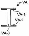
图1a为结构件或一部分垂直稳定翼的示意俯视图,所述结构件或垂直稳定翼为根据本发明的带有支撑组件和在所述支撑组件之间延伸之翼肋的流动体的例子,然而,所述流动体中并未示出预期使用的蒙皮壳,其中示意性地示出了用于布置本发明加强装置的中间区域或加强区域的位置,Figure 1a is a schematic top view of a structural member or part of a vertical stabilizing wing which is an example of a flow body according to the invention with support assemblies and ribs extending between said support assemblies, however , the intended use of the skin shell is not shown in the flow body, where the position of the intermediate region or reinforced region for arranging the reinforcing device of the present invention is schematically shown,
图1b示出了图1所示流动体的沿图1中线V2-V2以及两个箭头形式的观察方向的剖视图;Fig. 1 b shows a cross-sectional view of the flow body shown in Fig. 1 along the line V2-V2 in Fig. 1 and the viewing direction of two arrows;
图2为作为蒙皮壳的中间区域一部分的假想体积组件的示意剖视图,示出了在体积组件中轮转地设置带有加强组件的加强装置的实施例;FIG. 2 is a schematic cross-sectional view of an imaginary volume assembly as part of the middle region of the skin shell, showing an embodiment in which reinforcement means with reinforcement assemblies are arranged in rotation in the volume assembly;
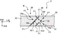
图3a为图1a和1b的流动体的区域S3的剖视图,其沿图1a和1b中心的线V3-V3和两个箭头形式的相关观察方向形成,所述示意图涉及根据本发明的带有T形翼肋结构的支撑结构与根据本发明示意实施例的蒙皮壳的组合,所述蒙皮壳包括内蒙皮,外蒙皮,和位于内蒙皮与外蒙皮之间的剪力吸收层;3 a is a sectional view of the region S3 of the flow body of FIGS. 1 a and 1 b, which is formed along the line V3-V3 in the center of FIGS. 1 a and 1 b and the relevant viewing directions in the form of two arrows. A combination of a support structure of a shaped rib structure and a skin shell according to an exemplary embodiment of the present invention, the skin shell comprising an inner skin, an outer skin, and a shear absorbing layer positioned between the inner skin and the outer skin;
图3b示出了根据图3a的结构件所使用的加强型材的剖面形状的第一实施例;Fig. 3b shows a first embodiment of the cross-sectional shape of the reinforcing profile used in the structure according to Fig. 3a;
图3c示出了根据图3a的结构件所使用的加强型材的剖面形状的第一实施例;Fig. 3c shows a first embodiment of the cross-sectional shape of the reinforcing profile used in the structure according to Fig. 3a;
图4a为图1a和1b的流动体的区域S3的剖视图,其沿图1a和1b中心的线V3-V3和两个箭头形式的相关观察方向形成,所述示意图涉及根据本发明的带有T形翼肋结构的支撑结构与根据本发明示意实施例的蒙皮壳的组合,所述蒙皮壳包括内蒙皮,外蒙皮,和位于内蒙皮与外蒙皮之间的剪力吸收层,其中支撑结构与蒙皮壳的附接根据本发明的另一示意实施例实现;Fig. 4 a is the sectional view of the region S3 of the flow body of Fig. 1 a and 1 b, and it is formed along the line V3-V3 of Fig. 1 a and 1 b center and the relevant viewing direction of two arrow forms, and described schematic diagram relates to according to the present invention with T A combination of a support structure of a shaped rib structure and a skin shell according to an exemplary embodiment of the present invention, the skin shell comprising an inner skin, an outer skin, and a shear absorbing layer positioned between the inner skin and the outer skin, wherein the attachment of the support structure to the skin shell is achieved according to another illustrative embodiment of the invention;
图4b为图1a和1b的流动体的区域S3的剖视图,其沿图1a和1b中心的线V3-V3和两个箭头形式的相关观察方向形成,所述示意图涉及根据本发明的带有T形翼肋结构的支撑结构与根据本发明示意实施例的蒙皮壳的组合,所述蒙皮壳包括内蒙皮,外蒙皮,和位于内蒙皮与外蒙皮之间的剪力吸收层,其中支撑结构与蒙皮壳的附接根据本发明的另一示意实施例实现;Figure 4b is a cross-sectional view of the area S3 of the flow body of Figures 1a and 1b, which is formed along the line V3-V3 in the center of Figures 1a and 1b and the relevant viewing directions in the form of two arrows, said schematic diagram relating to a flow cell according to the invention with T A combination of a support structure of a shaped rib structure and a skin shell according to an exemplary embodiment of the present invention, the skin shell comprising an inner skin, an outer skin, and a shear absorbing layer positioned between the inner skin and the outer skin, wherein the attachment of the support structure to the skin shell is achieved according to another illustrative embodiment of the invention;
图4c示出了根据本发明实施例的紧固装置的紧固件,其用于通过紧固件将支撑结构的连接组件连接至蒙皮壳;Fig. 4c shows the fasteners of the fastening device according to an embodiment of the present invention, which is used to connect the connection assembly of the support structure to the skin shell by fasteners;
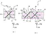
图5a为蒙皮壳的蒙皮部的带有一个加强型材组件的连接区域的示意实施例的剖视图,所述连接区域位于翼肋结构的上方,其中在蒙皮壳中在两个加强型材组件之间,结合入根据本发明的相互形成为X形的加强装置结构;Figure 5a is a cross-sectional view of a schematic embodiment of the connection area of the skin part of the skin shell with one reinforcement profile assembly above the rib structure, wherein in the skin shell there are two reinforcement profile assemblies between them, combined into the strengthening device structure mutually forming an X shape according to the present invention;
图5b为蒙皮壳的蒙皮部的带有多个加强型材组件的连接区域的另一示意实施例的剖视图,所述连接区域位于翼肋结构的上方,其中在蒙皮壳中在所述加强型材组件旁边之间,结合入根据本发明的相互形成为X形的加强装置结构;Figure 5b is a cross-sectional view of another schematic embodiment of the connection area of the skin part of the skin shell with a plurality of reinforcement profile assemblies above the rib structure, wherein in the skin shell the Between the sides of the reinforcement profile components, the structure of the reinforcement device forming an X shape according to the present invention is incorporated;
图5c为蒙皮壳的蒙皮部的连接区域的另一示意实施例的剖视图,所述连接区域位于翼肋结构的上方,其中在蒙皮壳中,结合入根据本发明的相互形成为X形的加强装置结构;Fig. 5c is a cross-sectional view of another schematic embodiment of the connection area of the skin part of the skin shell above the rib structure, wherein in the skin shell is incorporated the mutually formed X Shaped reinforcement device structure;
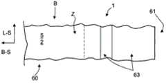
图6a为根据本发明蒙皮壳的第一实施例的立体俯视图,其示意地示出了支撑结构,其中在所示的蒙皮壳中,示意地引入了蒙皮壳的剪力吸收芯层内的加强区域或连接区域,Figure 6a is a perspective top view of a first embodiment of a skin shell according to the invention, schematically showing a support structure, wherein in the shown skin shell a shear absorbing core layer of the skin shell is schematically introduced Reinforced or connected areas within the
图6b为根据本发明蒙皮壳的第二实施例的立体俯视图,其示意地示出了图6a支撑结构,其中在所示的蒙皮壳中,示意地引入了蒙皮壳的剪力吸收芯层内的与图6a所示不同的加强区域或连接区域;Fig. 6b is a perspective top view of a second embodiment of the skin shell according to the present invention, which schematically shows the support structure of Fig. 6a, wherein in the shown skin shell, the shear force absorption of the skin shell is schematically introduced Reinforcement areas or connection areas in the core layer different from those shown in Figure 6a;
图7为蒙皮壳的在图6b中标为“A”之区域的第一示意实施例的剖视图,所述区域包括了树脂连接区域,以及翼肋结构的在具有连接区域的情况下设置的加强型材结构的实施例;Figure 7 is a cross-sectional view of a first schematic embodiment of the region of the skin shell, labeled "A" in Figure 6b, which region includes the resin connection region, and the reinforcement of the rib structure provided with the connection region Examples of profile structures;
图8为根据图7的蒙皮壳的在图6a和6b中标为“A”之区域的第二示意实施例的剖视图,所述区域包括了树脂连接区域,以及翼肋结构的在具有连接区域的情况下设置的加强型材结构的另一实施例;Fig. 8 is a cross-sectional view of a second schematic embodiment of the skin shell according to Fig. 7, in the region marked "A" in Figs. Another embodiment of the reinforced profile structure provided under the circumstances;
图9示出了已经结合入一行加强装置的蒙皮壳的一部分剖面,各包括两个相互形成为X形的加强组件的结构,其中图9示出了加强装置的加强组件;Figure 9 shows a section of a part of the skin shell that has been integrated into a row of reinforcing devices, each comprising two reinforcing components that are mutually formed into an X shape, wherein Figure 9 shows the reinforcing components of the reinforcing device;
图10a为已经结合入两行相邻排列的加强装置的蒙皮壳的一部分剖面,各包括两个相互形成为X形的加强组件的结构,其中图10a示出了加强装置的两个加强组件;Figure 10a is a section of a part of the skin shell that has been incorporated into two rows of adjacently arranged stiffeners, each comprising two mutually formed X-shaped stiffener assemblies, wherein Figure 10a shows two stiffener assemblies of the stiffener ;
图10b为已经结合入两行相邻排列的加强装置的蒙皮壳的一部分剖面,各包括两个相互形成为X形的加强组件的结构,其中图10b示出了加强装置的两个加强组件,其中所述加强装置设置为各加强装置的加强组件沿其纵向扩展方向相互咬合或联锁并且以拉链的方式相互设置;Fig. 10b is a partial cross-section of a skin shell that has been incorporated into two rows of adjacently arranged reinforcement devices, each comprising two mutually X-shaped reinforcement assemblies, wherein Fig. 10b shows two reinforcement assemblies of the reinforcement device , wherein the reinforcement device is configured such that the reinforcement components of each reinforcement device engage or interlock with each other along the longitudinal extension direction thereof and are arranged with each other in the form of a zipper;
图11为根据本发明的外边缘的实施例的剖视图,其带有不包括芯层的连接区域,还带有内蒙皮部和位于所述内蒙皮部上的外蒙皮部,其中根据本发明的加强装置已经插入芯层的端部区域中;Fig. 11 is a cross-sectional view of an embodiment of an outer edge according to the invention, with a connection region not including a core layer, and with an inner skin part and an outer skin part on said inner skin part, wherein according to the invention reinforcement means have been inserted into the end regions of the core;
图12为根据本发明的外边缘的另一实施例的剖视图,其带有不包括芯层的连接区域,还带有根据本发明的加强装置,其中加强装置已经插入芯层的端部区域中,其中所述芯层的端部区域包括相邻于所述已经插入的加强装置的加强区域;Figure 12 is a cross-sectional view of another embodiment of an outer edge according to the invention, with a connection area that does not include a core layer, and with a reinforcement device according to the invention, wherein the reinforcement device has been inserted into the end region of the core layer , wherein the end regions of the core layer include reinforcement regions adjacent to the inserted reinforcement means;
图13为根据本发明的外边缘的另一实施例的剖视图,其带有不包括芯层的连接区域,还带有根据本发明的加强装置,其中加强装置已经插入芯层的端部区域中,其中所述芯层的端部区域包括相邻区域,并且其端部的加强装置穿入所述加强区域;Figure 13 is a cross-sectional view of another embodiment of an outer edge according to the invention, with a connection area that does not include a core layer, and with a reinforcement device according to the invention, wherein the reinforcement device has been inserted into the end region of the core layer , wherein the end region of the core layer includes an adjacent region, and the reinforcement means at the end thereof penetrates into the reinforcement region;
图14为根据本发明的外边缘的另一实施例的剖视图,其带有不包括芯层的连接区域,还带有芯层的端部区域,其中单体的中间层已经插入所述芯层的端部区域中和所述连接区域中;Figure 14 is a cross-sectional view of another embodiment of an outer edge according to the invention, with a connection region not comprising a core layer, and also with an end region of the core layer, into which a monolithic intermediate layer has been inserted in the end region of and in the connecting region;
图15为根据图9的蒙皮壳的根据本发明的外边缘的实施例的剖视图,其中根据本发明的加强装置也已经插入所述芯层的端部区域;及FIG. 15 is a sectional view of an embodiment of the outer edge according to the invention of the skin shell according to FIG. 9 , wherein stiffeners according to the invention have also been inserted into the end regions of the core; and
图16为根据图11~15的蒙皮壳区域的一部分的俯视图。FIG. 16 is a plan view of a part of the skin shell area according to FIGS. 11 to 15 .
具体实施方式Detailed ways
根据本发明的蒙皮壳B或蒙皮板用作流动体(具体是流线型体)的主承受或主负荷承载覆盖组件或蒙皮组件。图1示出了作为本发明流动体或流线型体之实例的结构件1或部分垂直稳定翼的示意俯视图。结构件1包括支撑结构T和包围并且连接至所述支撑结构T的蒙皮壳。根据本发明,蒙皮壳B设计为三明治结构,其包括内蒙皮部11,外蒙皮部12,及位于内蒙皮部11和外蒙皮部12之间的剪力吸收芯层13或剪力吸收泡沫芯。内蒙皮部11和外蒙皮部12可各包括玻璃纤维或碳基材料,具体是可谓纤维复合塑料。内蒙皮部11和外蒙皮部12各延伸超过蒙皮壳B。就其位置和定向而言,所谓“内蒙皮部11”系指位于蒙皮壳B内部(即,面向由蒙皮B所覆盖的结构件1或流动体的内部或内部空间)的蒙皮部。在使用用于流动体的结构件1的情况下,“外蒙皮部12”面向在预期使用过程中发生在流动体上的流。The skin shell B or skin panel according to the invention is used as a main bearing or main load bearing cover assembly or skin assembly of a fluid body, in particular a streamlined body. FIG. 1 shows a schematic top view of a
图1b示出了沿图1a中线V2-V2的剖面并且示出了流动体1的包括两个相互分开的蒙皮壳B的部分,其中第一蒙皮壳B1和第二蒙皮壳B2相互平行并且相反分开地延伸。第一蒙皮壳B1和第二蒙皮壳B2的外表面形成流动体1的流面。例如,流动体1可为垂直稳定翼或垂直尾翼的一部分或为机翼或控制襟翼的一部分。在将流动体1作为垂直稳定翼或垂直尾翼的设计中,蒙皮壳B1,B2的外侧边最好设计为相互轴向对称。在将流动体1作为机翼或控制襟翼的设计中,蒙皮壳B1,B2的外侧边可设计为相互轴向对称或不对称。具体地,在航空器上使用这样的流动体1,就其在预期使用过程中发生的主流具有假想流向U,举例来说,第一蒙皮壳B的外侧边可形成流动体的吸力侧,而第二蒙皮壳B2的外侧边可形成流动体的压力侧。Figure 1b shows a section along the line V2-V2 in Figure 1a and shows a part of the
图1b仅示出了流动体1的仅一部分,当沿宽度方向或翼弦方向B-S观察时,由支撑结构T的支撑组件5或6形成的边缘侧或边缘端部件R1,R2界定出该部分。在支撑组件5,6上,以这样的方式附接有多个翼肋或翼肋结构R,即,它们相互分开地在所述支撑组件5,6之间。翼肋或翼肋结构R用作蒙皮壳组件B1或B2的加强组件。在其沿结构件1的宽度方向B-S放置的端部处,蒙皮壳组件B1或B2可设计为边缘部60,该边缘部例如至少在某些部分不包括泡沫制成的芯层13,参考图11和12描述此类蒙皮壳组件B1或B2。对于蒙皮壳组件B1或B2,当沿结构件1的宽度方向B-S放向观察时,可形成前后排列的两个或多个蒙皮壳组件B1或B2,其中,具体是可将两个蒙皮壳组件B1或B2分别固定到一个支撑组件5,6上固定。或者,可由两个以上的支撑组件5,6对相对于厚度方向D-S的两侧或其中一侧的一个蒙皮壳组件B1,B2进行支撑。这一结构中,流动体1由此包括两个以上的沿宽度方向B-S相互分开地延伸的支撑组件5,6,并且各蒙皮壳组件B1或B2在两个就所述宽度方向而言为外支撑组件5,6之间延伸并且延伸超过至少一个其它支撑组件。Fig. 1b only shows only a part of the
内蒙皮部11和外蒙皮部12各可由纤维玻璃或碳基材料制成,或具体可为纤维复合玻璃。内蒙皮部11和外蒙皮部12都延伸超过蒙皮壳B。一般而言,根据本发明或根据本发明多个方面的剪力吸收芯层13可设计为固体芯或泡沫芯。在芯层为固体芯的实施例中,芯层可包括塑料具体是聚乙烯及/或聚丁烯。作为代替或者除此之外,芯层可包括丙烯酸玻璃。在芯层为泡沫芯的实施例中,芯层可包括PVC泡沫或者发泡丙烯酸玻璃。根据本发明,为了影响芯层中的剪切应力,可将多个加强组件及/或加强装置10结合入蒙皮壳B,其中各加强装置10沿剪力吸收芯层13的厚度方向至少占据剪力吸收芯层13的85%,以改进蒙皮壳B的抗开裂性(图1a中未示出)。The
支撑结构T具体可包括(图1a和3):至少两个这样延伸的支撑组件或支撑型材5,6,即,其分别沿结构件1的纵向相邻并且沿结构件1的横穿方向或翼弦方向B-S隔开地延伸;及/或至少一个这样延伸的翼肋结构R,即,其在所述支撑组件之间延伸且横穿所述支撑组件,并且沿所述支撑组件的连接至蒙皮壳B用以将蒙皮壳B二维地支撑在支撑结构T上的纵向方向L-R延伸。加强翼肋结构R的加强翼肋的宽度沿结构件1的翼弦方向T-S延伸。沿结构件1的纵向方向L-S,支撑组件5,6可分别连接至端部E1或E2。支撑组件5,6具体可为纵向加强组件或纵向部件或翼梁。例如,若所述流动体为航空器组件,则支撑组件5,6可为机身,机翼,垂直稳定翼,控制襟翼,或水平稳定翼的部件或翼梁。支撑结构T各翼肋结构R或多翼肋结构R中的至少一个包括:沿翼肋的纵向方向L-R二维地连接至所述蒙皮壳的凸缘组件22,以及沿凸缘组件22的横穿方向Q-R从凸缘组件22或蒙皮壳B凸出的翼肋21。翼肋21和凸缘组件22可形成为一个组件。具体地,可单独或共同地将各翼肋21和凸缘组件22形成为一个由纤维复合塑料制成的组件。图1a和1b引入了坐标系,其以蒙皮壳的纵向方向L-B,蒙皮壳的横向方向B-B,和蒙皮壳的厚度方向D-B为轴表示所述蒙皮。The support structure T may in particular comprise ( FIGS. 1 a and 3 ): at least two support assemblies or
图1a还示出了泡沫芯的由根据本发明的加强装置进行加强的中间区域或区域。Figure 1a also shows the central region or region of the foam core which is reinforced by the reinforcing means according to the invention.
根据本发明的主负荷承载蒙皮壳B具体可用于制造此类结构件1。由于蒙皮壳B已被固定至支撑结构T以形成流动体的外部,并且由此是形成绕所述流动体之流的关键,并且在这一过程中承受由空气形成的外力,并且在预定的程度上对撞击蒙皮壳B的物体所带来的影响进行补偿,因此所述蒙皮壳B为结构件的主负荷承载结构部分。在对撞击蒙皮壳B的物体所带来的影响进行补偿过程中,根据本发明的蒙皮壳B可证在经受物体撞击之后仍然保持为整体稳定的实体,然后所述实体继续承受与流相关的力。The primary load-carrying skin shell B according to the invention can be used in particular for the manufacture of such
根据本发明,提供了用于此类结构件1的主负荷承载蒙皮壳B。为了将蒙皮壳B固定至支撑组件,所述蒙皮壳B包括带有外边缘61和连接区域63的外边缘部60,连接区域63沿边缘61延伸,并且连接区域63具体设计为将蒙皮壳B固定至支撑组件5,6或固定至附接结构(图11~16)。为了这一目的,连接区域63可包括容纳紧固件的槽或插孔或孔。作为代替或者除此之外,连接区域63可粘合或焊接至支撑组件5,6或固定至附接结构。According to the invention, a primary load carrying skin shell B for such a
图1a还示出了预定区域中蒙皮壳B的(具体是芯层53或芯层53的泡沫芯的)由根据本发明的加强装置进行加强的中间区域或区域。FIG. 1 a also shows the intermediate region or region of the skin shell B (in particular of the core 53 or of the foam core of the core 53 ) reinforced by the reinforcing means according to the invention in predetermined regions.
由于蒙皮壳B已经附接至支撑结构T或者附接至附接结构以形成流动体的外部,并且由此是形成绕所述流动体之流的关键,因此所述蒙皮壳B为结构件1的主负荷承载结构部分。Since the skin shell B has been attached to the support structure T or to an attached structure to form the exterior of the flow body, and thus is the key to forming the flow around said flow body, said skin shell B is a
本发明的示意实施例中,为了影响芯层13中的剪应力和防止开裂形成,蒙皮壳B包括多个设于中间区域Z中的加强组件及/或加强装置10,各包括至少两个设于蒙皮壳B的连续体积组件V(图2)中的加强组件的组合。图2示出了此类假想体积组件V,其采用带边缘线K的矩形平行六面体的形式。为了进行说明,图2还示出了中间区域的纵向方向L-Z,并且利用所述蒙皮壳的坐标轴L-B,Q-B,及D-B示出了蒙皮壳的坐标系。具体地,沿中间区域Z的纵向方向L-Z以相邻排列的方式布置加强装置10。根据图2的示意实施例中,加强装置10视为包括四个加强组件10a,10b,10c,10d的组合,其中在加强组件10a,10b,10c,10d的组合中,各所述加强组件沿蒙皮壳B的厚度方向D-B具有相同的定向,最多有不超过10度的偏离,并且其中沿其它坐标方向L-B,Q-B方向加强组件的朝向是轮转的。In the exemplary embodiment of the invention, in order to influence the shear stress in the
本发明的一个方面涉及蒙皮壳B的在翼肋结构R之间二维地延伸的区域,下文参考图1所示的示意实施例描述所示区域。因此,提供了流动体的结构件1,其至少带有一个蒙皮壳B的并且带有支撑结构T以对蒙皮壳B进行附接,其中三明治结构的蒙皮壳B包括内蒙皮部31,外蒙皮部32,和位于内蒙皮部31,外蒙皮部32之间的剪力吸收芯层33或泡沫层,芯层33二维地互连内蒙皮部31与外蒙皮部32(图7,8)。这一结构中,在支撑组件T和翼肋结构R之间延伸并且位于内蒙皮部31与外蒙皮部32之间的剪力吸收芯层33包括多个沿泡沫层或剪力吸收芯层33的纵向扩展相邻排列的剪力吸收芯层部33a这一结构中,沿所述芯层的纵向方向L-V(图6a和6b)跨剪力吸收芯层部33的纵向扩展而穿过所述芯层33的芯层加强区域37使得位于接触侧的剪力吸收芯层部33a互连在一起。One aspect of the invention relates to the region of the skin shell B extending two-dimensionally between the rib structures R, which region is described below with reference to the schematic embodiment shown in FIG. 1 . Thus, a
这一结构中,芯层加强区域37可在内蒙皮部31与外蒙皮部32之间延伸。这一结构中,具体可设置为将芯层加强区域37连接至内蒙皮部31和外蒙皮部32,从而将芯层加强区域37连接至内蒙皮部31和外蒙皮部32。芯层加强区域37具体可包括这样的材料,即,其强度为芯层加强区域37的两倍。根据蒙皮壳B的一个实施例,芯层加强区域37的厚度17a为蒙皮壳B在这一位置的宽度的0.1~2.0倍,其中垂直于所述蒙皮的纵向扩展测量所述厚度。In this configuration, the
芯层加强区域37具体可包括树脂。图3示出了根据本发明的结构件的示意实施例,其中虚线示出了单个剪力吸收芯层部33a的边缘线或芯层加强区域37的路线。The
这一情况下,支撑结构T具体可包括至少两个支撑组件5,6(图3未示出)和至少一个连接至蒙皮壳B的翼肋结构R,各所述支撑组件沿结构件1的纵向方向L-S延伸,所述翼肋结构R用以将蒙皮壳B二维地支撑在支撑结构T(图1)上。In this case, the support structure T may in particular comprise at least two
支撑组件5,6具体可设计为参考图1和2描述的示意实施例。The
根据图3的结构件实施例中,这样设置芯层加强区域37的路线,即,形成矩形剪力吸收芯层部33a,或者相反地,所述芯层包括由芯层加强区域37进行互连的剪力吸收芯层部33a。这一结构中,设置多个具体沿翼肋结构的纵向方向L-R延伸的芯层加强区域37-1,37-2,37-3。本结构中,所谓“沿”具体系指在翼肋结构的纵向方向L-R延伸的芯层加强区域37-1,37-2,37-3的定向,相对于翼肋结构的局部纵向方向L-R或翼肋结构R的纵向方向的定向之间形成的局部角度偏离最大不超过30度。芯层加强区域37可为弯曲的或直的。图5中,作为例子,仅引入了与一个芯层加强区域37相关的芯层剪力吸收纵向方向L-V。此外,设置芯层加强区域37-4,其横穿沿翼肋结构的纵向方向L-R延伸的芯层加强区域37-1,37-2,37-3。由此,具体地,设置剪力吸收芯层部33a以形成蒙皮壳B。In the embodiment of the structural member according to FIG. 3 , the
根据本发明结构件的一个示意实施例,在剪力吸收芯层33中沿芯层加强区域37的周围区域结合入多个根据本发明的蒙皮壳B加强装置(例如,图3中,此类周围区域或中间区域包括标号Z)。这一结构中,沿加强区域的纵向方向L-V或沿中间区域Z的纵向方向的加强组件及/或加强装置10设置为连续排列(串行排列)。这一结构中,例如对于在两个翼肋结构R之间及/或一个翼肋结构R与一个边缘区域60之间延伸的蒙皮壳B,可沿在蒙皮壳B中延伸芯层加强区域37并在该区域的两侧将加强组件及/或加强装置10结合入所述蒙皮壳B的剪力吸收芯层33中。一般而言,在芯层加强区域37的两侧用于放置加强装置10的周围区域可沿其纵向扩展进行延伸,并且最大延伸距离为芯层加强区域37的各个位置上的蒙皮壳B的两倍厚度的十倍,最好为两倍。According to an exemplary embodiment of the structural member of the present invention, a plurality of skin shell B reinforcements according to the present invention are incorporated in the
参考图7,8,9,10a,10b描述的本发明示意实施例会对剪力吸收芯层33造成某些损坏,若此类损坏发生在芯层加强区域37两侧中的第一侧,则无法通过芯层加强区域37而转移至与第一侧相对的第二侧。The illustrative embodiments of the invention described with reference to Figures 7, 8, 9, 10a, 10b cause some damage to the
本发明的一个方面为用于结构件1的主负荷承载蒙皮壳B,所述蒙皮壳B在其二维延伸的内部区域而形成为前述的三明治形状的组件。下文将参考图6~11描述本发明的这一方面,其中蒙皮壳B的内部区域50示出为:形成为三明治状组件的蒙皮壳B带有内蒙皮部51,外蒙皮部52,以及位于内蒙皮部51和外蒙皮部52之间并使之互连的剪力吸收芯层53。这些组件的特性如前所述。图6~10中,所示实施例的某些结构件和组件各自的标号与前图中表述某些功能和特性的标号相同。One aspect of the invention is the primary load-carrying skin shell B for the
蒙皮壳B设计为通过外边缘部60固定至支撑组件5,6及/或翼肋结构R,外边缘部60带有外边缘61和不具有芯层的连接区域63,连接区域63与内蒙皮部51和外蒙皮部52沿边缘61延伸。图6~8所示的蒙皮壳实施例中,芯层区域在连接区域63的蒙皮部51,52中相互抵靠的位置处结束。这一区域中,可通过紧固件或其它方式对蒙皮壳进行紧固。图9和10所示的蒙皮壳实施例中,蒙皮部51,52之间设有单体的(monolithic)中间层65。外边缘部60中设有过渡区域62,当从内部区域50观察时,剪力吸收芯层53在过渡区域62中结束,即,剪力吸收芯层53的外边缘55位于或延伸至过渡区域62中。过渡区域62中,可设置厚度小于单体中间层65之厚度的区域62以减小蒙皮壳的剖面厚度。图11~14所示的实施例中,外边缘部61中在蒙皮部51,52之间不设有单体层,因为在过渡区域中所述单体层相应地逐渐变小并且在外部边缘61之前结束。The skin shell B is designed to be fixed to the
对比图6~10与图1~3可知,边缘61或边缘55沿结构件1的纵向方向L-S延伸,并且连接区域63从内部区域50延伸之结构件1的宽度方向B-S。Comparing FIGS. 6-10 with FIGS. 1-3 , the
根据本发明,具体是可沿蒙皮壳B的外边缘部60将穿过剪力吸收芯层53的加强装置10结合入将芯层的端部区域56。According to the invention, in particular along the
具体可将根据本发明这一方面的蒙皮壳B容纳在支撑结构T中并且如本文所述地固定至所述支撑结构T。根据本发明的这一方面,如参考图1所述,蒙皮壳B具体还可在支撑组件5,6与翼肋结构R之间延伸。视需要,作为代替或除此之外,剪力吸收芯层53可包括多个沿剪力吸收芯层53的纵向扩展相邻设置的剪力吸收芯层部53a(图6,9,或10中未示)。这一结构中,如前所述,各剪力吸收芯层部33a在接触侧由芯层加强区域37互连在一起,所述加强区域沿所述加强区域的芯层的纵向方向L-V延伸跨剪力吸收芯层部33或63的纵向扩展而穿过所述加强区域的芯层。In particular the skin shell B according to this aspect of the invention may be housed in a support structure T and fixed to said support structure T as described herein. According to this aspect of the invention, the skin shell B can in particular also extend between the
根据本发明,在不包括芯层的连接区域63的就内部区域60而言的前方形成中间区域62,在所述中间区域62中,剪力吸收芯层53的厚度沿其边缘55的方向连续减小,并同时至少在剪力吸收芯层53的面向外蒙皮部52的侧边与外蒙皮部52之间或剪力吸收芯层53的面向内蒙皮部51的侧边与内蒙皮部之间形成单体中间层65的楔形区段。本示意实施例中,具体可在芯层的沿蒙皮壳B的外部边缘部30的端部区域67中结合入根据本实施例的加强装置10;10e,10f,所述加强装置10;10e,10f穿过剪力吸收芯层并且部分地穿入单体中间层65的两个楔形区段。According to the invention, an
用于设置加强装置的芯层的端部区域56可从芯层的端部的边缘延伸,最大延伸距离可为芯层的端部的边缘处的蒙皮壳B之厚度的四倍。The
一般而言,根据本发明多个方面的加强装置的结构及/或设计可相同。一般而言,可在芯层的端部区域56中这样设置加强组件10;10a,10b,10c,10d;10e,10f及/或加强装置中的一部分,即,其端部F1至少部分地穿入内蒙皮部11及/或外蒙皮部12,如图5a,5b,7,8,9,10a,10b,及11所示。内蒙皮部11或51(图11~15)及/或外蒙皮部12或52(图11~15)各可包括多个蒙皮层(未图示)。这一结构中,具体可将加强组件及/或加强装置10a,10b,10c,10d中的一部分这样设于蒙皮壳B中,即,其端部F1至少部分地穿入内蒙皮部11或51及/或外蒙皮部12或52。In general, the structure and/or design of reinforcement devices according to aspects of the invention may be the same. 10a, 10b, 10c, 10d; 10e, 10f and/or part of the reinforcement means may be arranged in the
作为代替或者除此之外,多个加强组件10;10a,10b,10c,10d;10e,10f各自至少部分地穿入加强区域37。这一结构中,一个加强组件的一个端部F2穿入加强区域37或已经插入所述加强区域37(图7,8,和13)。Alternatively or additionally, a plurality of
图3示出了根据本发明的支撑结构T和与蒙皮壳22的组合,所述支撑结构T具体带有整体为T形的翼肋结构R的支撑构架,所述蒙皮壳结构22包括内蒙皮部11,外蒙皮部12,及位于内蒙皮部11和外蒙皮部12之间的剪力吸收芯层13。图3示出了图1a和1b的流动体1的区域S的剖视图,所述剖视图为沿图1a和1b中V3-V3线以及箭头形式的相关观察方向作出,所述示意剖面描述了根据本发明的带有T形翼肋结构的支撑结构与蒙皮壳B的组合。根据本发明的示意实施例,流动体1的蒙皮壳B包括内蒙皮部11,外蒙皮部12,及位于内蒙皮部11和外蒙皮部12之间的剪力吸收芯层13。根据本发明,可将加强装置10或翼肋结构加强型材组件插入芯层13中位于应力结构R的旁边的位置。一般而言,支撑结构T也可包括仅具有翼肋21而不具有板形连接件22的支撑结构,或可为仅包括板形连接件22的支撑结构。Figure 3 shows a support structure T according to the invention in combination with a
根据本发明,这一结构中,可沿横穿翼肋结构的纵向方向L-R的蒙皮壳剖面在蒙皮壳B中插入或结合入一或多个成型支架或翼肋结构加强型材组件V0,所述蒙皮壳剖面形成支撑结构T(或例如蒙皮壳B的支撑组件5,6及/或翼肋结构R)的连接区域。例如,对于所述蒙皮壳B上支撑组件5,7的连接区中或支撑结构的翼肋结构R的连接区域中的蒙皮壳B加强,将成型支架设为支撑组件加强成型支架或支撑结构加强型材组件或翼肋结构加强成型支架或支撑组件加强型材组件。连接区域14系这样的区域,即,为蒙皮壳B的在其沿蒙皮壳B的厚度方向D-B观察的二维延伸中通过其面向蒙皮壳B的侧边覆盖或横切界定出支撑结构T或支撑组件5,6或支撑结构或翼肋结构R的区域,或相对于蒙皮壳B限制各支撑结构T的区域。带有翼肋结构R的实施例中,支撑结构T的朝向蒙皮壳B的侧边为翼肋结构R的凸缘组件的朝向蒙皮壳B的侧边。成型支架V0使得凸缘组件22或内蒙皮部11与在发生外部损坏的过程中稳定蒙皮壳B的外蒙皮部12互连。According to the invention, in this structure, one or more profiled brackets or rib structure reinforcement profile assemblies V0 can be inserted or incorporated in the skin shell B along a skin shell section transverse to the longitudinal direction L-R of the rib structure, Said skin shell profile forms the connection area of the support structure T (or, for example, the
所述至少一个成型支架V0或多个成型支架V0可设计为细长形或板形的加强成型支架。这一结构中,成型支架V0可沿基准纵向方向延伸,所述基准纵向方向定向为沿各支撑结构T的纵向扩展。图1a所示的支撑组件的纵向扩展由此沿蒙皮壳B的边缘区域延伸,所述边缘区域靠着蒙皮壳B的相邻边缘区域,由此成型支架V0的基准纵向方向沿蒙皮壳B的边缘区域延伸。支撑结构的或者翼肋结构R的基准纵向方向沿所述支撑结构或翼肋结构R的纵向扩展的方向延伸,具体是沿支撑结构方向或翼肋结构的纵向方向L-R延伸,即,平行于支撑结构方向或翼肋结构的纵向方向L-R延伸或与之成角度地延伸。若设置多个成型支架V0,具体是沿在所述实施例中作为翼肋结构的纵向方向L-R的基准纵向方向观察时,所述多跟成型支架V0可并排相邻地设置与延伸。The at least one shaped bracket V0 or the plurality of shaped brackets V0 can be designed as elongated or plate-shaped reinforced shaped brackets. In this configuration, the profiled support V0 may extend along a reference longitudinal direction oriented along the longitudinal expansion of the respective support structure T. The longitudinal extension of the support assembly shown in FIG. 1a thus extends along the edge region of the skin shell B which abuts against the adjacent edge region of the skin shell B, whereby the reference longitudinal direction of the profiled bracket V0 is along the skin The edge region of shell B extends. The reference longitudinal direction of the support structure or of the rib structure R extends in the direction of the longitudinal extension of said support structure or of the rib structure R, in particular in the direction of the support structure or of the longitudinal direction L-R of the rib structure, i.e. parallel to the support The structural direction or longitudinal direction L-R of the rib structure extends or extends at an angle thereto. If a plurality of shaped brackets V0 are provided, especially when viewed along the reference longitudinal direction in the described embodiment as the longitudinal direction L-R of the rib structure, the multiple shaped brackets V0 can be arranged and extended side by side adjacently.
这一结构中,基准纵向方向为由成型支架V0进行加强之区域或为负载状况进行稳定之区域的延伸方向。具体地,所述要进行加强或稳定区域例如可为支撑组件5,6或翼肋结构R的支撑结构T的连接区域。这具体可为凸缘组件22和蒙皮壳B的连接区域。通过设置成型支架V0,可防止或局部地制止芯层13因外部负载作用于这一区域所导致的主应力位于芯层13中而发生开裂。计算以及广泛的试验业已表面根据本发明的这些措施有良好的效果。In this structure, the reference longitudinal direction is the direction of extension of the area reinforced by the profiled bracket V0 or stabilized for the load situation. Specifically, the region to be strengthened or stabilized may be, for example, the connection region of the
就此而言,所谓“翼肋结构的纵向方向L-R”系指沿蒙皮壳B的纵向扩展和沿翼肋21的纵向方向延伸的方向。若设置多个翼肋,则翼肋结构的纵向方向L-R具体可沿这些翼肋中的一个或者主翼肋的纵向方向延伸。所谓“翼肋结构的横穿方向Q-R”系指垂直于翼肋结构的纵向方向L-R、穿过蒙皮壳B的纵向、且沿宽度方向延伸的方向,换言之,即,翼肋21的主延伸。图3还示出了翼肋结构宽度方向B-R,其垂直于翼肋结构的纵向方向L-R和翼肋结构的横穿方向Q-R定向。In this connection, the term "longitudinal direction L-R of the rib structure" means the direction along the longitudinal expansion of the skin shell B and along the longitudinal direction of the
图3a所示的示意实施例中,以沿翼肋的宽度方向B-R连续排列的方式,或者以沿翼肋结构的纵向方向L-R并排相邻排列的方式,设置多个翼肋结构加强型材组件V0。图3示出了翼肋结构加强型材组件V0在凸缘组件22和蒙皮壳B的整个连接区域上分布的翼肋结构R实施例。如图3所示的翼肋结构R的示意实施例的剖面中,总共设有10个沿翼肋结构的纵向方向L-R并排相邻排列的翼肋结构加强成型支架。图3中,由标号V1,V3或V2,V4表示就沿翼肋结构的纵向方向L-R而言的外加强成型支架。一般而言,具体可在凸缘组件22的整个区域或者在凸缘组件22的一部分均匀隔开地分布翼肋结构加强型材组件V0。In the schematic embodiment shown in Fig. 3a, a plurality of rib structure reinforcing profile components V0 are arranged in a continuous arrangement along the width direction B-R of the rib structure, or in a side-by-side arrangement along the longitudinal direction L-R of the rib structure. . FIG. 3 shows an embodiment of the rib structure R in which the rib structure reinforcing profile assembly V0 is distributed over the entire connection area of the
通过沿翼肋结构R布置加强装置10,翼肋结构R的区域中蒙皮壳的损坏(例如,以剪力吸收芯层13中形成开裂的形式)就可能不会转移到或以减小的程度转移到蒙皮壳B的相邻于翼肋结构R延伸的二维延伸区域。此外,反之,通过沿翼肋结构R布置加强装置10,蒙皮壳B的损坏(例如,以蒙皮壳B的相邻于翼肋结构R延伸的二维延伸区域中的剪力吸收芯层13中形成开裂的形式)就可能不会转移到或以减小的程度转移到蒙皮壳B的位于翼肋结构R的区域中的区域。By arranging the
根据本发明结构件1的示意实施例,可在翼肋结构R的沿翼肋结构的纵向方向L-R并排相邻排列的翼肋结构加强型材组件V0之间设置至少一个加强装置10。根据图3所示的示意实施例,可在就翼肋结构的横穿方向Q-R而言的外翼肋结构加强型材组件V1和V3或V2或V4之间设置根据本发明的加强装置10。可沿翼肋结构的纵向方向L-R连续排列地设置前述加强装置10。此外,在多个翼肋结构加强组件之间(换言之,例如,在两个,三个,或四个外翼肋结构加强组件之间),都设置至少一个根据本发明的加强组件及/或至少一个加强装置10。这一结构中,加强装置10和各相关的翼肋结构加强组件也可设置为相对于翼肋结构的横穿方向Q-R相互偏离。这些示意实施例中,最好沿翼肋结构的纵向方向L-R连续排列地重复设置这些装置,并且可在蒙皮壳B中的翼肋结构R的整个长度设置这些结构。According to an exemplary embodiment of the
根据本发明的蒙皮壳B与翼肋结构R的组合中,能够在蒙皮壳中设置加强组件及/或至少一个加强装置10以代替根据一个本发明所述类型的翼肋结构加强伦敦组件V0。In the combination of the skin shell B and the rib structure R according to the invention, it is possible to provide a reinforcing element and/or at least one
图3示意性地示出泡沫芯13中的破碎形成:物体F1利用脉冲F撞击蒙皮壳B。标号F3和F4示出了在泡沫芯13中形成的开裂。FIG. 3 schematically shows the formation of fractures in the foam core 13 : an object F1 hits the skin shell B with a pulse F. FIG. References F3 and F4 show cracks formed in the
一般而言,本发明的蒙皮壳B的实施例中,加强装置10可包括至少一个加强组件。这一结构中,加强组件可设计为例如包括圆形或矩形剖面的钉状加强组件。In general, in the embodiments of the skin shell B of the present invention, the reinforcement means 10 may comprise at least one reinforcement component. In this configuration, the reinforcing element can be designed, for example, as a spike-shaped reinforcing element comprising a circular or rectangular cross-section.
加强装置10各包括至少一个加强组件10a,10b,10c,10d,10e,10f。此类加强组件10a,10b,10c,10d,10e,10f具体可设计为细长形或板形的加强成型支架。由此,加强组件10a,10b,10c,10d,10e,10f具体可为销形。图2,5a,5b,9,10a,10b中,各所示的加强组件10a,10b,10c,10d,10e,10f包括标号10a,10b,10e,10f。The
根据图5c所示的本发明的蒙皮壳B与支撑组件5,6及/或蒙皮壳B上的翼肋结构R之组合的另一实施例,可在蒙皮壳B的连接区域14或者视需要沿宽度方向B相邻于连接区域设置加强组件10a,10b,10c,10d,10e,10f或加强装置10,具体是根据本发明的及/或本文所述类型的加强组件或加强装置。这一结构中,具体可设置为不将型材组件插入连接区域(图5c)。这一结构中,加强组件10a,10b,10c,10d,10e,10f或加强装置10可沿翼肋结构的宽度方向B-R或沿支撑组件的宽度方向将加强组件10a,10b,10c,10d,10e,10f或加强装置10排成一行,及/或沿翼肋组件的纵向方向L-R或沿支撑组件的纵向方向并排相邻排列。这些情况下,如图5c所示,可将以X形布置的多对加强组件10a,10b,10c,10d,10e,10f结合入蒙皮壳B。According to another embodiment of the combination of the skin shell B of the present invention and the
一般而言,加强组件沿蒙皮壳B的厚度方向延伸或与蒙皮壳B成角度地延伸,并且这一结构中,加强组件这样位于芯层13内,即,其端部F1与蒙皮部11,12分开,或者其端部F1中的一个与蒙皮部11,12中的一个分开,或者可这样设置加强组件,即,所述加强组件使得内蒙皮部11和外蒙皮部12互连,换言之,所述加强组件部分地进入内蒙皮部11及/或外蒙皮部12。内蒙皮部51及/或外蒙皮部52可分别包括多个蒙皮层,及/或加强装置10,10a,10b,10c,10d;10e,10f中的至少一部分可这样设置,即,其端部F1或端部F1中的一个穿入内蒙皮部51及/或外蒙皮部52,至少穿入第一蒙皮层。一般而言,加强组件由此至少部分地穿入剪力吸收芯层13。Generally speaking, the stiffener elements extend in the thickness direction of the skin shell B or extend at an angle to the skin shell B, and in this structure, the stiffener elements are located in the
加强组件具体可这样位于蒙皮壳B中,即,各加强组件的纵向方向与蒙皮壳的厚度方向之间的角度为45度~10度的范围内。Specifically, the reinforcement components can be located in the skin shell B in such a way that the angle between the longitudinal direction of each reinforcement component and the thickness direction of the skin shell is in the range of 45 degrees to 10 degrees.
一般而言,根据本发明的加强装置10可沿基准纵向方向连续布置,所述基准方向在示意实施例中为翼肋结构的纵向方向L-R。此外,加强组件V也可沿横穿基准纵向方向或翼肋结构的纵向方向L-R的方向连续排列。这一结构中,加强装置10可排列为为多行相邻排列的加强装置10。这些多行加强装置10也可排列为加强装置10沿基准纵向方向或翼肋结构的纵向方向L-R交叠的网状或联锁形状(图10b),其中加强装置10还可设置为沿沿基准纵向方向或翼肋结构的纵向方向L-R相互分开。具体地,多行加强装置可相邻地延伸。In general, stiffening means 10 according to the invention may be arranged consecutively along a reference longitudinal direction, which in the illustrated embodiment is the longitudinal direction L-R of the rib structure. Furthermore, the reinforcing elements V may also be arranged continuously in a direction transverse to the reference longitudinal direction or the longitudinal direction L-R of the rib structure. In this structure, the reinforcing
就加强装置10或加强组件的排列而言的基准方向系为了负载状况通过多个加强装置10或加强组件进行加强或稳定之区域的延伸方向。下文中,所述区域也指加强区域或中间区域Z。具体是,例如,所述要进行加强或稳定的区域可在支撑组件(例如翼肋结构)的连接区域的旁边,在其内,或沿其延伸,或者沿边缘区域延伸,并由此形成为从连接区域或边缘区域到蒙皮壳B之延伸的二维区域的过渡区域,可防止或局部地制止因芯层13中的所述过渡区域中的主应力而造成所述过渡区域发生开裂。计算以及广泛的试验业已表面根据本发明的这些措施有良好的效果。The reference direction with respect to the arrangement of
通过虚线分别表示图3所示的将蒙皮壳B固定至翼肋结构R的示意实施例中,以及图5a,5b,9,10a,10b所示的将蒙皮壳B固定至加强组件的实施例中,其中,在所示的剖面中,实线表示处于切割剖面面中的加强组件,而虚线表示与这一剖面分开至剖面的加强组件。The schematic embodiment of fixing the skin shell B to the rib structure R shown in Figure 3 and the fixing of the skin shell B to the stiffener assembly shown in Figures 5a, 5b, 9, 10a, 10b are respectively indicated by dashed lines In the embodiment wherein, in the cross-section shown, the solid lines represent the reinforcement components in the plane of the cut section, while the dashed lines represent the reinforcement components separated from this cross-section.
一般而言,可沿上述基准纵向方向连续排列地布置,或者并排相邻地排列成一行或多行加强组件或加强装置。图3所示实施例中,加强组件沿上述基准纵向方向例如沿翼肋结构的纵向方向L-R连续排列。这一结构中,销形元件可设置为相对于连续排列的直线或翼肋结构的纵向方向L-R相互偏离,即,所示销形元件可横穿蒙皮壳的纵向扩展相互分开。Generally speaking, the reinforcement components or reinforcement devices can be arranged in a continuous row along the above-mentioned reference longitudinal direction, or arranged side by side and adjacently in one or more rows. In the embodiment shown in Fig. 3, the reinforcing elements are arranged continuously along the aforementioned reference longitudinal direction, for example along the longitudinal direction L-R of the rib structure. In this configuration, the pin-shaped elements may be arranged mutually offset with respect to the longitudinal direction L-R of the continuous line or rib structure, ie the shown pin-shaped elements may be separated from each other across the longitudinal extension of the skin shell.
此外,图3的示意实施例中,加强组件10a,10b设于蒙皮壳B的两个横向区域Z1,Z2中,其中加强组件10a,10b沿翼肋结构的纵向方向L-R延伸并且沿蒙皮壳部14的横向端部横向延伸,所示加强组件10a,10b的宽度延伸穿过翼肋结构的纵向方向L-R,并且沿蒙皮壳B的纵向扩展方向延伸。Furthermore, in the schematic embodiment of Fig. 3, the
作为代替或者除此之外,加强组件10a,10b可插入加强区域中,加强组件10a,10b位于蒙皮壳部14内并且的蒙皮壳部14的横向端部横向在沿芯层13中延伸。图3中,由标号V3和V4表示此类加强组件组。Alternatively or in addition, reinforcing
一般而言,为了影响剪应力并且避免在芯层13中形成开裂,本发明的蒙皮壳B的实施例可包括多个至少设于一个蒙皮壳的加强区域或中间区域中的加强装置10,其中各加强装置10包括至少两个设于蒙皮壳B的假想体积组件V(图2)中的加强组件的组合。蒙皮壳B的至少一个中间区域Z的尺寸和位置这样确定,即,所述中间区域Z根据在某一给定的应用情况下可预期的外部负载使得整个蒙皮壳B稳定,虽然各中间区域Z中由于这些负载而产生剪应力,这是因为存在加强组件而不会在这一中间区域Z的芯层13中形成开裂或停止形成开裂。这一结构中,所述至少一个中间区域Z的位置和尺寸以及其中的加强组件的排列类型最好这样选择,即,不仅在所述中间区域Z之内,而且在所述中间区域Z之外,在蒙皮壳B的芯层13中形成开裂的危险为最小。这一结构中,所述至少一个中间区域Z的位置和尺寸取决于应用情况,换言之,取决于带有蒙皮壳的整个结构件以及相关的预期外部负载。In general, in order to influence the shear stresses and avoid the formation of cracks in the
根据本发明的一实施例,加强装置10的加强组件可分为多组。这一结构中,多体积组件V(图2)中的各个组件中以分组的形式设置加强组件10a,10b,10c,10d或10e,10f,其中,一般而言,各加强组件10a,10b,10c,10d或10e,10f组各包括一个连续体积组件V,各连续体积组件V至少两个加强组件10a,10b,10c,10d或10e,10f。由此,蒙皮壳B的各连续体积组件中设有一组加强组件。一组加强组件中的各加强组件10a,10b,10c,10d,或10e,10f在蒙皮壳B中的位置或定向相近,并且各加强组件相对于蒙皮壳B的厚度方向D-B的角度偏离最大不超过30度。此外,一组加强组件相对于蒙皮壳B的其它坐标方向L-B,B-B为轮转设置。According to an embodiment of the present invention, the reinforcement components of the
图2示出了轮转对齐的一组四个加强组件10a,10b,10c,10d的例子。图2示出了此类假想体积组件V,其采用带边缘线K的矩形平行六面体的形式。图2还示出了中间区域的纵向方向L-Z,并且还利用所述蒙皮壳的坐标轴L-B,Q-B,及D-B示出了蒙皮壳的坐标系。具体地,沿中间区域Z的纵向方向L-Z以并排相邻排列的方式排列加强装置10。根据图2的示意实施例中,加强装置10视为包括四个加强组件10a,10b,10c,10d的组合,其中在加强组件10a,10b,10c,10d的组合中,最多有不超过10度的偏离各所述加强组件沿蒙皮壳B的厚度方向D-B具有相同的定向,并且其中加强组件的朝向沿其它坐标方向-B,Q-B是轮转的。Figure 2 shows an example of a set of four
这一结构中,一般而言,根据本发明的加强装置10或多个的加强装置10可位于这样延伸的虚拟线上,即,所述虚拟线在平行于基准线或翼肋结构的纵向方向L-R或与之成角度,及/或从横穿翼肋结构的纵向方向L-R的方向观察还是相互偏离的。In this structure, in general, the
某一情况下,一组加强组件可包括两个沿上述基准纵向方向相互成大致X形的加强组件10e,10f。由此,蒙皮壳B的这一实施例中,加强装置10的至少一部分包括成对的沿蒙皮壳B的纵向扩展方向相互成大致X形的加强组件10a,10b,10c,10d;10e,10f。此类X形加强组件组中,两个加强组件可设置为相互分开或者相互抵靠或者作为十字形结构插入蒙皮壳B中。例如,分别位于两条侧边Z1和Z2其中一条侧边上的多对加强装置10这样相互设置,即,这些对中的一对形成为沿翼肋结构的纵向方向L-R的X形加强装置。In a certain case, a set of reinforcement components may include two
可以多种方式设计和构造加强装置10。根据本发明的示意实施例,加强装置10包括多个沿翼肋结构的纵向方向L-R连续排列的销形加强组件10e,10f的组合,其中各对加强组件10e,10f设于根据本发明的体积组件V中。此外,所有或者部分的插入蒙皮壳B或其区域中的加强组件可因此可为销形设计。再者,在加强组件的一端或两端可包括足状的加宽部或钩状件,以在蒙皮壳B中进行定位,及/或空间固定,或锚定。加强组件的这一设计的优点在于,当承受外部动态损坏负载时,各加强组件仍然固定至蒙皮壳B。The
作为这一加强装置的代替,加强装置可包括多个板形(图中未示)加强组件的组合,所述板形组件沿其第一纵向扩展在内蒙皮部11与外蒙皮部12之间延伸并且穿过位于所述内蒙皮部11与外蒙皮部12之间的剪力吸收芯层13。沿其垂直于所述第一纵向扩展对齐的纵向方向,这些板形加强组件沿翼肋结构的纵向方向L-R延伸。As an alternative to this reinforcement device, the reinforcement device may comprise a combination of a plurality of plate-shaped (not shown in the figures) reinforcement components extending along their first longitudinal direction between the
这一结构中,例如,具体是各对前述加强组件的销形或板形加强组件10e,10f可相互抵靠。此外,具体是各对前述加强组件的销形或板形加强组件10e,10f可沿翼肋结构的纵向方向L-R相互分开。根据一示意实施例,这一结构中,各对前述加强组件的销形或板形加强组件10e,10f之间的最大距离为各位置处蒙皮壳B的厚度的1.5倍。In this structure, for example, the pin-shaped or plate-shaped reinforcing
板形加强组件的加强装置设计中,可将两个或多个板形加强组件设置成沿翼肋结构的纵向方向L-R看为网格状或互锁状。In the design of the reinforcing device of the plate-shaped reinforcing component, two or more plate-shaped reinforcing components can be arranged in a grid-like or interlocking shape viewed along the longitudinal direction L-R of the rib structure.
根据本发明的加强装置10的实施例中,加强装置10或多个加强装置可延伸穿入内蒙皮部11和外蒙皮部12,或者可通过端部固定在所述蒙皮部11,12中。作为代替或除此之外,加强装置10或多个加强装置通过其各自的朝向蒙皮部的端部可抵靠着内蒙皮部11和外蒙皮部12,或其结束处可与所述蒙皮部11,12相隔一定的距离。In an embodiment of the reinforcing
一般而言,加强组件10;10a,10b,10c,10d;10e,10f中的至少一部分可这样设于蒙皮壳B中,即,其端部F1至少部分地穿入内蒙皮部11及/或外蒙皮部12,如图5a,5b,7,8,9,10a,10b,及11。内蒙皮部11或51(图11)及/或外蒙皮部12或52(图11)可分别包括多个芯层(未图示)。这一结构这,加强组件10a,10b,10c,10d中的至少一部分可这样设于蒙皮壳B中,即,其端部F1至少部分地穿入内蒙皮部11或51及/或外蒙皮部12或52。In general, at least a part of the reinforcing
根据本发明,一般而言,加强组件可包金属性材料及/或非金属性材料,具体可包括纤维复合塑料材料。碳,纤维玻璃,石英,凯夫拉尔,及/或陶瓷可用作非结束性材料。According to the present invention, generally speaking, the reinforcement component can be clad with metallic material and/or non-metallic material, specifically, it can include fiber composite plastic material. Carbon, fiberglass, quartz, Kevlar, and/or ceramic can be used as non-finish materials.
根据本发明结构件的另一实施例,剪力吸收芯层13包括至少一个芯层加强区域37,并且最好包括多个芯层加强区域37(图4),通过所述芯层加强区域连接剪力吸收芯层部33a,该多个芯层部33a沿剪力吸收芯层33或泡沫层的纵向扩展连续排列。各芯层加强区域37沿所述芯层的纵向方向L-V(图3)横穿剪力吸收芯层部13的纵向扩展而穿过所述芯层13,并且在这一过程中在内蒙皮部11与外蒙皮部12之间延伸。图3所示的根据本发明结构件的示意实施例中,虚线示出了单个剪力吸收芯层部33a的边缘性,或者芯层加强区域37的路线。图3所示的结构件实施例中,这样设置芯层加强区域37的路线,即,形成矩形剪力吸收芯层部33a,或者相反地,所述芯层包括由芯层加强区域37互连的剪力吸收芯层部33a。这一结构中,芯层加强区域37具体可连接至内蒙皮部11和外蒙皮部12,从而使得芯层加强区域37连接至内蒙皮部11和外蒙皮部12。According to another embodiment of the structural element according to the invention, the shear-absorbing
根据蒙皮壳B的一实施例,芯层加强区域37的厚度17a为蒙皮壳B在这一位置的宽度的0.1~2.0倍,其中垂直于所述蒙皮的纵向扩展测量所述厚度。According to an embodiment of the skin shell B, the thickness 17a of the
通过插入芯层加强区域37的加强装置10,可有效地防止或停止蒙皮壳的损坏(具体是以剪力吸收芯层13中形成开裂的形式)从芯层加强区域37的一侧转移到芯层加强区域的另一侧。By inserting the
芯层加强区域37具体可包括这样的材料,即,其强度为芯层加强区域37的两倍。这一结构中,芯层加强区域37具体可包括树脂。The core-reinforced
根据本发明的带有翼肋结构R的蒙皮壳B的实施例中,根据本发明实施例的沿翼肋结构的纵向方向L-R连续排列的多个加强组件10可各自穿入至少一个芯层加强区域37。具体是,芯层加强区域37的纵向方向具体可沿翼肋结构的纵向方向L-R或沿翼肋结构R的整个长度延伸。这一结构中,芯层加强区域37可平行于纵向方向L-R或与之成角度地延伸。具体可在沿翼肋结构的纵向方向L-R延伸两个横向区域Z1,Z2中的至少一个设置至少一个芯层加强区域37,所示芯层加强区域37带有位于其上的加强装置。In the embodiment of the skin shell B with the rib structure R according to the present invention, a plurality of
根据本发明实施例的多个加强装置10可设于此类加强区域37。图7示出了这样的示意实施例,即,X形设置的成对的加强组件10或10e,10f或结构穿过芯层加强区域37,其中加强组件10e,10f的中心部位于芯层加强区域17内。图7中,所述加强组件的X形布置的两个加强组件由标号10e和10f表示。多个沿芯层加强区域37的纵向方向布置的X形加强组件10可排列为沿基准纵向方向连续排列,并且相互跟随或相互抵靠及/或相互分开。A plurality of
作为上述本发明实施例的代替或除此之外,可沿翼肋结构的纵向方向L-R并且沿芯层加强区域37的纵向方向设置连续排列的X形结构10-1,10-2,其中,连续排列的X形结构10-1,10-2设于在芯层加强区域37的两侧。图8所示的示意实施例中,在同一位置处,沿芯层加强区域17的纵向方向并且相对于芯层加强区域17相互相对地设置X形结构或加强组件10的成对加强组件10-1,10-2。在此处所谓的加强组件的“X形”结构中,所述X形加强组件结构沿各自的基准纵向方向相互分开,由此,图7,8,9,10a和10b中,所示一对加强装置中的一个加强装置包括虚线以表示这一加强装置位于各标绘出的平面之后。图8中,由标号10e和10f表示所述加强组件的X形结构的两个加强组件。图8中,芯层加强区域37的纵向方向从图8观察者垂直延伸至图面,而第一X形结构10-1位于芯层加强区域37的左手侧,第二X形结构10-2位于芯层加强区域37的右手侧。所示的示意实施例中,加强组件的位于芯层加强区域37上的端部穿入芯层加强区域37的区域。或者,加强组件的X形结构的加强组件也设为相邻于加强区域,即,离开一定的距离。示意实施例中,朝向芯层加强区域37的外端部与所示芯层加强区域之间的最大距离为这一位置处蒙皮壳B的厚度。作为这些示意实施例的变化,X形结构10-1,10-2或可位于芯层加强区域37的沿芯层加强区域37的纵向方向相对两侧上。As an alternative or in addition to the embodiments of the invention described above, a continuous array of X-shaped structures 10-1, 10-2 may be provided along the longitudinal direction L-R of the rib structure and along the longitudinal direction of the
具体地,在两个加强组件的X形结构中,两个加强组件10e,10f可相互抵靠,或者两个加强组件10e,10f可通过其各自的中间部互连。由此,举例来说,加强组件10e,10f中的一个可包括容纳另一加强组件的容纳装置(例如,孔)。这一结构中,可这样连接两个加强组件10e,10f,即,其非旋转地互连以吸收剪力吸收芯层13中产生的剪应力及/或停止或防止在其中发生任何开裂。若芯层加强区域37的两侧中的第一侧发生损坏,则参考图7和8描述的本发明示意实施例会使得剪力层吸收芯层13的任何损坏而不会通过芯层加强区域37将损坏传递至位于相对于第一侧的第二侧。Specifically, in the X-shaped configuration of the two reinforcement assemblies, the two
一般而言,用于本发明的多个方面的加强装置的结构及/或设计可为相同。一般而言,可在芯层的端部区域56中这样设置加强组件10;10a,10b,10c,10d;10e,10f及/或加强装置中的至少一部分,即,其端部F1至少部分地穿入内蒙皮部11及/或外蒙皮部12,如图5a,5b,7,8,9,10a,10b,及11所示。内蒙皮部11或51(图6~10)及/或外蒙皮部12或52(图6~10)各可包括多个个蒙皮层(未图示)。这一结构中,具体可将加强组件及/或加强装置10a,10b,10c,10d中的一部分这样设于蒙皮壳B中,即,其端部F1至少部分地穿入内蒙皮部11或51及/或外蒙皮部12或52。In general, the structure and/or design of reinforcement devices used in various aspects of the invention may be the same. 10a, 10b, 10c, 10d; 10e, 10f and/or at least a part of the reinforcement means may be arranged in the
作为代替或者除此之外,多个加强组件10;10a,10b,10c,10d;10e,10f各自至少部分地穿入加强区域37。这一结构中,一个加强组件的一个端部F2穿过加强区域37或已经插入所述加强区域37(图4,5,和8)。Alternatively or additionally, a plurality of
如图9,10a和10b所示,可在带有或不带有加强区域37的蒙皮壳B中沿基准纵向方向设置多个加强装置,其中各加强装置可由一组包括X形结构的加强组件10a,10b形成。这一结构中,可沿基准纵向方向连续排列地设置多对X形的加强组件(图9)。如图10a和10b所示,也可设置多行此类加强装置,其中沿横穿基准纵向方向的方向相邻设置。图10b示出了相邻设置的多行加强装置10-1,10-2可设计为,加强组件的纵向延伸从基准纵向方向看它们的端部交汇叠合。As shown in Figures 9, 10a and 10b, a plurality of reinforcing devices can be arranged along the reference longitudinal direction in the skin shell B with or without the reinforced
根据本发明的一方面,提供带有根据所述之一实施例之结构件的流动体。根据本发明,所述结构件为主负荷承载结构部分,并且所述蒙皮壳及翼肋结构由此为主负荷承载结构件。According to an aspect of the present invention, there is provided a fluid body with a structural element according to one of the described embodiments. According to the invention, the structural member is the main load-carrying structural part, and the skin shell and rib structure is thus the main load-carrying structural part.
本发明的另一方面涉及蒙皮壳B的在翼肋结构R之间二维延伸的区域,并且下文参考图6a和6b所示的示意实施例进行描述。由此,提供了流动体的结构件1,其带有至少一个蒙皮壳B以在结构件1外部形成流面,并且带有支撑结构T以附接各蒙皮壳B,其中如上述参考图1~5所述之蒙皮壳B形成为三明治形,并且包括内蒙皮部31,外蒙皮部32,和位于内蒙皮部31,外蒙皮部32之间的剪力吸收芯层33或泡沫层,所述芯层二维地将内蒙皮部31与外蒙皮部32互连(图7,8)。这一结构中,在支撑组件T和翼肋结构R之间延伸并且位于内蒙皮部31与外蒙皮部32之间的剪力吸收芯层33包括多个沿泡沫层或剪力吸收芯层33的纵向扩展相邻排列的剪力吸收芯层部33a。沿所述芯层的纵向方向L-V(图6a,6b)横穿剪力吸收芯层部33的纵向扩展而穿入所述芯层33的芯层加强区域37使得位于接触侧的剪力吸收芯层部33a互连在一起。Another aspect of the invention relates to the region of the skin shell B extending two-dimensionally between the rib structures R, and is described below with reference to the schematic embodiment shown in Figures 6a and 6b. There is thus provided a
由此,芯层加强区域37的沿蒙皮壳B的纵向扩展的延伸以及沿芯层部33a的延伸可以有多种方式。与芯层加强区域37的沿蒙皮壳B的纵向扩展的路线相对应,图6a所示实施例中芯层部33a设置为棋盘状,并且在图6b所示实施例中芯层部33a设为与棋盘状结构相比沿纵向方向相互偏离。一般而言,芯层加强区域37这样延伸,即,芯层加强区域37,沿蒙皮壳B的纵向扩展看,触碰矩形平行六面体形状的芯层补33a的横向边缘或角。Thus, the extension of the
这一结构中,芯层加强区域37在内蒙皮部31与外蒙皮部32之间延伸。这一结构中,具体可设置为将芯层加强区域37连接至内蒙皮部31和外蒙皮部32,从而将芯层加强区域37连接至内蒙皮部31和外蒙皮部32。芯层加强区域37具体可包括这样的材料,即,其强度为芯层加强区域37的两倍。根据蒙皮壳B的一个实施例,芯层加强区域37的厚度17a为蒙皮壳B在这一位置的宽度的0.1~2.0倍,其中垂直于所述蒙皮的纵向扩展测量所述厚度。In this structure, the core reinforced
芯层加强区域37具体可包括树脂。图3示出了根据本发明的结构件的示意实施例,其中虚线示出了单个剪力吸收芯层部33a的边缘线或芯层加强区域37的路线。The
这一情况下,支撑结构T具体可包括至少两个支撑组件5,6(图6未示出)和至少一个连接至蒙皮壳B的翼肋结构R,各所述支撑组件沿结构件1的纵向方向L-S延伸,所述翼肋结构R用以将蒙皮壳B二维地支撑在支撑结构T(图1a,1b)上。In this case, the support structure T may specifically comprise at least two
翼肋结构R的剖面具体可为T形。图2示出了根据本发明的翼肋结构R的示意实施例,包括:翼肋21和从翼肋21延伸出的凸缘组件22,凸缘组件22连接至蒙皮壳B的表面区并且附接至所述表面区。凸缘组件22的长度沿翼肋结构的纵向方向L-R延伸,并且凸缘组件22的沿翼肋结构的横穿方向Q-R延伸,其中翼肋21沿翼肋结构的宽度方向B-R从凸缘组件22凸出,所述宽度方向垂直于翼肋结构的纵向方向L-R和翼肋结构的横穿方向Q-R(图3)。The cross-section of the rib structure R may specifically be T-shaped. Figure 2 shows a schematic embodiment of a rib structure R according to the invention, comprising: a
具体可根据参考图1和2所述的示意实施例设计支撑组件5,6。In particular, the
根据图6的结构件实施例中,这样形成芯层加强区域37的路线,即,可形成矩形的剪力吸收形成部33a。这一结构中,设置多个具体沿翼肋结构的纵向方向L-R延伸的芯层加强区域37-1,37-2,37-3。本结构中,所谓“沿”具体系指可在芯层加强区域37-1,37-2,37-3的沿翼肋结构的纵向方向L-R延伸的定向相对于与翼肋结构的局部纵向方向L-R的定向或翼肋结构R的纵向方向的定向之间可形成有最大不超过30度的局部角度偏离。芯层加强区域37可为弯曲的或直的。图5中,作为例子,仅引入了与一个芯层加强区域37相关的芯层剪力吸收纵向方向L-V。此外,设置芯层加强区域37-4,其横穿沿翼肋结构的纵向方向L-R延伸的芯层加强区域37-1,37-2,37-3。由此,具体地,设置剪力吸收芯层部33a以形成蒙皮壳B。In the embodiment of the structural element according to Fig. 6, the course of the
根据本发明结构件的一个示意实施例,在剪力吸收芯层33中沿多个芯层加强区域37的周围区域Z结合入根据本发明的蒙皮壳B加强装置(例如,图6中,此类周围区域或中间区域包括标号Z)。这一结构中,沿加强区域的纵向方向L-V或沿中间区域Z的纵向方向的加强组件及/或加强装置10设置为连续排列。这一结构中,例如在两个翼肋结构R之间延伸的蒙皮壳B中,可沿在蒙皮壳B中延伸的芯层加强区域37并在该区域的两侧将加强组件及/或加强装置10结合入所述蒙皮壳B的剪力吸收芯层33中。一般而言,用于在芯层加强区域37的两侧设置加强装置10的周围区域可沿其纵向扩展进行延伸,并且最大延伸距离为芯层加强区域37的各个位置处的蒙皮壳B之厚度的两倍。According to an exemplary embodiment of the structural member of the present invention, in the shear force absorbing
如前述参考图2和3所述,可将加强组件及/或加强装置10与芯层加强区域33结合入蒙皮壳B,由此用相同的标号表示类似功能的组件。图6和7中,示出了两个位于芯层加强区域37旁边以及沿其设置的加强装置10。图7和8所示的加强装置10及其布置的实施例实现为类似于图2或3所示的加强装置10及其布置的实施例。可如参考图3和4所述地设置加强装置10或其加强组件的设计和布置。As previously described with reference to Figures 2 and 3, reinforcement components and/or
这一情况下,根据本发明,具体可设置多个根据本发明实施例设置的加强装置10,其沿加强区域的纵向方向L-V连续排列并且穿入芯层加强区域37。图8示出了示出了这样的示意实施例,即,X形的加强组件10或10e,10f对或结构穿入芯层加强区域37,其中加强组件10e,10f的中心部位于芯层加强区域17内。作为代替或除此之外,加强组件10也可沿芯层的加强区域纵向方向L-V位于芯层加强区域37的旁边。图7和图8中,所述加强组件的X形布置的两个加强组件由标号10e和10f表示。多个沿芯层加强区域37的纵向方向布置的X形加强组件10可排列为沿基准纵向方向连续排列,并且相互跟随或相互抵靠及/或相互分开。In this case, according to the invention, in particular a plurality of reinforcing
作为上述本发明实施例的代替或除此之外,可沿翼肋结构的纵向方向L-R并且沿芯层加强区域37的纵向方向设置连续排列的X形结构10-1,10-2,其中,连续排列的X形结构10-1,10-2设于在芯层加强区域37的两侧。图8所示的示意实施例中,在同一位置处,沿芯层加强区域17的纵向方向并且相对于芯层加强区域17相互相对地设置X形结构或加强组件10的一对加强组件10-1,10-2。在此处所谓的加强组件的“X形”结构中,所述X形加强组件结构沿各自的基准纵向方向相互分开,由此,图7,8,9,10a和10b中,所示一对加强装置中的一个加强装置包括虚线以表示这一加强装置位于各标绘出的平面之后。图8中,由标号10e和10f表示所述加强组件的X形结构的两个加强组件。图8中,芯层加强区域37的纵向方向从图8观察者垂直延伸至图面,而第一X形结构10-1位于芯层加强区域37的左手侧,第二X形结构10-2位于芯层加强区域37的右手侧。所示的示意实施例中,加强组件的位于芯层加强区域37上的端部穿入芯层加强区域37的区域。或者,加强组件的X形结构的加强组件也设为相邻于加强区域,即,离开一定的距离。示意实施例中,朝向芯层加强区域37的外端部与所示芯层加强区域之间的最大距离为这一位置处蒙皮壳B的厚度。作为这些示意实施例的变化,X形结构10-1,10-2或可位于芯层加强区域37的沿芯层加强区域37的纵向方向相对两侧上。As an alternative or in addition to the embodiments of the invention described above, a continuous array of X-shaped structures 10-1, 10-2 may be provided along the longitudinal direction L-R of the rib structure and along the longitudinal direction of the
参考图7~10b描述的本发明示意实施例会对剪力吸收芯层33造成某些损坏,若此类损坏发生在芯层加强区域37两侧中的第一侧,则无法通过芯层加强区域37而转移至与第一侧相对的第二侧。The illustrative embodiment of the invention described with reference to Figures 7-10b would cause some damage to the
本发明的另一个方面涉及用于结构件1的主负荷承载蒙皮壳B,所述蒙皮壳B在其二维延伸的内部区域以前述参考图1~5及5~7所示的方式形成为前述的三明治形状的组件。下文将参考图9和11描述本发明的这一方面,其中蒙皮壳B的内部区域50示出为:形成为三明治状组件的蒙皮壳B带有内蒙皮部51,外蒙皮部52,以及位于内蒙皮部51和外蒙皮部52之间并使之互连的剪力吸收芯层53。这些组件的特性如前所述。图9和10中,所示实施例的某些结构件和组件各自的标号与前图中表述某些功能和特性的标号相同。Another aspect of the invention relates to a primary load-carrying skin shell B for a
根据本发明,具体是可沿蒙皮壳B的外边缘部60将穿过剪力吸收芯层53的加强装置10结合入将芯层的端部区域56。According to the invention, in particular along the
可如参考图4和5或7和8所述地设计加强装置。这一结构中,具体可使用加强组件10e,10f的X结构。图9中,可设置沿结构件1的宽度方向B-S连续排列的两个X结构10-1和10-2。一般而言至少可沿沿结构件1的宽度方向B-S设置至少一个加强组件10具体是至少一个加强组件10的X结构。较佳地,沿结构件1的纵向方向L-S,换言之,沿剪力吸收芯层33的边缘55,可设置多个加强装置10或10-1及/或10-2。The reinforcing means may be designed as described with reference to FIGS. 4 and 5 or 7 and 8 . In this structure, specifically, the X structure of the
作为上述本发明实施例的代替或除此之外,可沿翼肋结构的纵向方向L-R并且沿芯层加强区域37的纵向方向设置连续排列的X形结构10-1,10-2,其中,连续排列的X形结构10-1,10-2设于在芯层加强区域37的两侧。图5所示的示意实施例中,在同一位置处,沿芯层加强区域17的纵向方向并且相对于芯层加强区域17相互相对地设置X形结构或加强组件10的一对加强组件10-1,10-2。图5中,由标号10e和10f表示所述加强组件的X形结构的两个加强组件。图8中,芯层加强区域37的纵向方向从图6观察者垂直延伸至图面,而第一X形结构10-1位于芯层加强区域17的左手侧,第二X形结构10-2位于芯层加强区域17的右手侧。所示的示意实施例中,加强组件的位于芯层加强区域17上的端部穿入芯层加强区域37的区域。或者,加强组件的X形结构的加强组件也设为相邻于加强区域,即,离开一定的距离。示意实施例中,朝向芯层加强区域17的外端部与所示芯层加强区域之间的最大距离为这一位置处蒙皮壳B的厚度。作为这些示意实施例的变化,X形结构10-1,10-2或可位于芯层加强区域17的沿芯层加强区域17的纵向方向相对两侧上。As an alternative or in addition to the embodiments of the invention described above, a continuous array of X-shaped structures 10-1, 10-2 may be provided along the longitudinal direction L-R of the rib structure and along the longitudinal direction of the
具体地,在两个加强组件的X形结构中,两个加强组件10e,10f可相互抵靠,或者两个加强组件10e,10f可通过其各自的中间部互连。由此,举例来说,加强组件10e,10f中的一个可包括容纳另一加强组件的容纳装置(例如,孔)。这一结构中,可这样连接两个加强组件10e,10f,即,其非旋转地互连以承受剪力吸收芯层13中产生的剪应力及/或停止或防止其中发生任何的开裂。Specifically, in the X-shaped configuration of the two reinforcement assemblies, the two
若芯层加强区域37的两侧中的第一侧发生损坏,则参考图7和8描述的本发明示意实施例会导致剪力层吸收芯层13损坏而不会通过芯层加强区域37将损坏传递至位于相对于第一侧的第二侧。If damage occurs to the first of the two sides of the core reinforced
参考图3,3b,4b描述的本发明示意实施例会对剪力吸收芯层13造成某些损坏,若此类损坏发生在芯层加强区域17两侧中的第一侧,则无法通过芯层加强区域17而转移至与第一侧相对的第二侧。The illustrative embodiment of the invention described with reference to Figures 3, 3b, 4b would cause some damage to the
具体可将根据本发明这一方面的蒙皮壳B容纳在支撑结构T中并且如图1a,1b,和2或图5a,5b,5c所述地固定至所述支撑结构T。根据本发明的这一方面,如参考图1a和1b所述,蒙皮壳B具体还可在支撑组件5,6与翼肋结构R之间延伸。视需要,作为代替或除此之外,剪力吸收芯层53可包括多个沿剪力吸收芯层53的纵向扩展相邻设置的剪力吸收芯层部53a(图9或10中未示),如前文参考图3~8所示。这一结构中,如参考图6所述,沿加强区域的芯层的纵向方向L-V横越剪力吸收芯层部33或63的纵向扩展而穿过所述芯层加强33的芯层加强区域37使得位于接触侧的各剪力吸收芯层部33a互连在一起。In particular a skin shell B according to this aspect of the invention may be housed in a support structure T and fixed to said support structure T as described in Figures 1a, 1b, and 2 or Figures 5a, 5b, 5c. According to this aspect of the invention, the skin shell B can in particular also extend between the
根据本发明,在不包括芯层的连接区域63的从内部区域60观察的前方形成中间区域62,在所述中间区域62中,剪力吸收芯层53的厚度沿其边缘55的方向连续减小,并同时至少在剪力吸收芯层53的面向外蒙皮部52的一侧与外蒙皮部52之间或剪力吸收芯层53的面向内蒙皮部51的一侧与内蒙皮部之间形成单体中间层65的楔形区段。本示意实施例中,具体可在芯层的沿蒙皮壳B的外部边缘部30的端部区域67中结合入根据本实施例的加强装置10;10e,10f,所述加强装置10;10e,10f穿过剪力吸收芯层并且部分地穿入单体中间层65的两个楔形区段。According to the invention, in front of the connecting
用于设置加强装置的芯层的端部区域56可从芯层的端部的边缘延伸,最大延伸距离可为芯层的端部的边缘处的蒙皮壳B之厚度的四倍。The
一般而言,用于本发明的多个方面的加强装置的结构及/或设计可为相同。In general, the structure and/or design of reinforcement devices used in various aspects of the invention may be the same.
Claims (21)
Translated fromChineseApplications Claiming Priority (17)
| Application Number | Priority Date | Filing Date | Title |
|---|---|---|---|
| US36585710P | 2010-07-20 | 2010-07-20 | |
| US36588210P | 2010-07-20 | 2010-07-20 | |
| US36586310P | 2010-07-20 | 2010-07-20 | |
| US36587310P | 2010-07-20 | 2010-07-20 | |
| DE102010027695.2 | 2010-07-20 | ||
| US61/365,882 | 2010-07-20 | ||
| US61/365,873 | 2010-07-20 | ||
| DE102010031688ADE102010031688A1 (en) | 2010-07-20 | 2010-07-20 | Main load-bearing planking shell for structural component of flow body, has sandwich component with inner skin section and outer skin section, where core layer is located between shear loads |
| DE102010027696.0 | 2010-07-20 | ||
| DE102010027696ADE102010027696A1 (en) | 2010-07-20 | 2010-07-20 | Main load-bearing sheeting shell for structural component of flow body, has inner main section, outer main section and core layer that is shear-loaded between main sections |
| US61/365,863 | 2010-07-20 | ||
| DE102010031688.1 | 2010-07-20 | ||
| DE102010031690ADE102010031690A1 (en) | 2010-07-20 | 2010-07-20 | Covering plate for sandwich component in planar extending interior region of airplane, has control line coupled to two ports for creation of optical check signal, where control line is provided with specific amount of tear resistance |
| DE102010027695ADE102010027695A1 (en) | 2010-07-20 | 2010-07-20 | Structural component for flow body, is provided with main load-bearing sheathing shell and support structure for fixing load-bearing sheathing shell |
| US61/365,857 | 2010-07-20 | ||
| DE102010031690.3 | 2010-07-20 | ||
| PCT/EP2011/003643WO2012010306A1 (en) | 2010-07-20 | 2011-07-20 | Main-load-bearing planking shell and structural component and flow body comprising such a main-load-bearing planking shell |
Publications (2)
| Publication Number | Publication Date |
|---|---|
| CN103153782Atrue CN103153782A (en) | 2013-06-12 |
| CN103153782B CN103153782B (en) | 2017-02-15 |
Family
ID=45496539
Family Applications (4)
| Application Number | Title | Priority Date | Filing Date |
|---|---|---|---|
| CN201180045269.6AExpired - Fee RelatedCN103153782B (en) | 2010-07-20 | 2011-07-20 | Main load skin shell and structural and flow bodies with the main load skin shell |
| CN201180045272.8AActiveCN103118940B (en) | 2010-07-20 | 2011-07-20 | Structural element having at least one primary load-carrying skin shell and a support structure coupling the primary load-carrying skin shell and flow body having such a structural element |
| CN201180045258.8AActiveCN103118939B (en) | 2010-07-20 | 2011-07-20 | Main load-bearing covering shell and the structural element with main load-bearing covering shell |
| CN2011800453006APendingCN103118943A (en) | 2010-07-20 | 2011-07-20 | Planking panel for a structural component, flow body comprising such a planking panel and device for monitoring material damage on such a planking panel |
Family Applications After (3)
| Application Number | Title | Priority Date | Filing Date |
|---|---|---|---|
| CN201180045272.8AActiveCN103118940B (en) | 2010-07-20 | 2011-07-20 | Structural element having at least one primary load-carrying skin shell and a support structure coupling the primary load-carrying skin shell and flow body having such a structural element |
| CN201180045258.8AActiveCN103118939B (en) | 2010-07-20 | 2011-07-20 | Main load-bearing covering shell and the structural element with main load-bearing covering shell |
| CN2011800453006APendingCN103118943A (en) | 2010-07-20 | 2011-07-20 | Planking panel for a structural component, flow body comprising such a planking panel and device for monitoring material damage on such a planking panel |
Country Status (4)
| Country | Link |
|---|---|
| US (4) | US20130273301A1 (en) |
| EP (4) | EP2595877B1 (en) |
| CN (4) | CN103153782B (en) |
| WO (4) | WO2012010305A1 (en) |
Cited By (1)
| Publication number | Priority date | Publication date | Assignee | Title |
|---|---|---|---|---|
| CN108081681A (en)* | 2017-12-15 | 2018-05-29 | 中国航空工业集团公司成都飞机设计研究所 | A kind of mixing sandwich structure and its processing method with sloped transition area |
Families Citing this family (19)
| Publication number | Priority date | Publication date | Assignee | Title |
|---|---|---|---|---|
| WO2012010305A1 (en) | 2010-07-20 | 2012-01-26 | Airbus Operations Gmbh | Structural component comprising at least one main-load-bearing covering shell and a carrier structure for fixing the main-load-bearing covering shell, and flow body comprising such a structural component |
| EP3470339A1 (en)* | 2013-06-27 | 2019-04-17 | Airbus Operations GmbH | Panel member for an airframe |
| EP2842865B1 (en)* | 2013-08-28 | 2019-12-18 | Airbus Operations GmbH | Window panel for an airframe and method of producing same |
| JP6169465B2 (en) | 2013-10-02 | 2017-07-26 | 三菱重工業株式会社 | Joints and aircraft structures |
| DE102013223262A1 (en)* | 2013-11-14 | 2015-05-21 | Bayerische Motoren Werke Aktiengesellschaft | Method for checking a component |
| ES2848224T3 (en)* | 2014-01-20 | 2021-08-05 | Siemens Gamesa Renewable Energy As | Delamination indicator |
| TWI666359B (en)* | 2014-03-31 | 2019-07-21 | 日商東麗股份有限公司 | Dyed artificial leather and manufacturing method thereof |
| CN103954416B (en)* | 2014-04-29 | 2017-05-03 | 北京交通大学 | Analysis method for deflection of foam core structure after being impacted and application thereof |
| DE102014015976A1 (en) | 2014-10-31 | 2016-05-04 | Airbus Defence and Space GmbH | Composite construction for increased durability |
| CN104554701B (en)* | 2015-01-23 | 2016-07-06 | 南京航空航天大学 | Suturing skill reinforced foam sandwich shape for hat Material Stiffened Panel structure and forming method thereof |
| AT517198B1 (en)* | 2015-04-24 | 2021-12-15 | Facc Ag | Control surface element for an airplane |
| DE102015111936A1 (en) | 2015-07-22 | 2017-01-26 | Airbus Operations Gmbh | sandwich structure |
| FR3040684A1 (en)* | 2015-09-04 | 2017-03-10 | Airbus Operations Sas | SIMPLIFIED RIB FOR A CENTRAL AIRCRAFT SAIL BOAT. |
| GB2565351A (en)* | 2017-08-11 | 2019-02-13 | Airbus Operations Ltd | Panel assembly |
| US10422742B2 (en)* | 2017-10-18 | 2019-09-24 | The Boeing Company | Moisture detection system |
| US10656081B2 (en) | 2017-10-18 | 2020-05-19 | The Boeing Company | Synchronized phased array and infrared detector system for moisture detection |
| US10906659B2 (en)* | 2018-04-03 | 2021-02-02 | Rohr, Inc. | Structured panel with structural reinforcement(s) |
| DE102018120905A1 (en)* | 2018-08-27 | 2020-02-27 | Wobben Properties Gmbh | Fiber composite semifinished product, fiber composite component, rotor blade element, rotor blade and wind power plant as well as method for producing a fiber composite semifinished product and method for producing a fiber composite component |
| CN118257766B (en)* | 2024-05-30 | 2024-08-30 | 洛阳船舶材料研究所(中国船舶集团有限公司第七二五研究所) | Metal frame and large-thickness sandwich composite material connecting structure and forming method |
Citations (5)
| Publication number | Priority date | Publication date | Assignee | Title |
|---|---|---|---|---|
| US4910065A (en)* | 1987-10-15 | 1990-03-20 | The Boeing Company | Reinforced honeycomb core sandwich panels and method for making same |
| US5736222A (en)* | 1995-11-01 | 1998-04-07 | The Boeing Company | Interlaced Z-pin structures |
| EP0904929B1 (en)* | 1997-09-25 | 2002-11-20 | The Boeing Company | Method for forming a caul plate during moulding of a part |
| US20060188696A1 (en)* | 2005-02-24 | 2006-08-24 | The Boeing Company | Reinforced rampdown for composite structural member and method for same |
| CN201254685Y (en)* | 2008-07-17 | 2009-06-10 | 南京工业大学 | A composite bridge deck |
Family Cites Families (40)
| Publication number | Priority date | Publication date | Assignee | Title |
|---|---|---|---|---|
| US3803485A (en) | 1970-02-16 | 1974-04-09 | Battelle Development Corp | Indicating coating for locating fatigue cracks |
| DE2132446A1 (en)* | 1971-06-30 | 1973-01-18 | Ver Flugtechnische Werke | SANDWICH PANEL WITH SHEARING FORCE CONNECTION |
| US3837985A (en)* | 1972-02-24 | 1974-09-24 | Whittaker Corp | Multi-directional reinforced composite and method of making the same |
| GB2029019A (en)* | 1978-08-12 | 1980-03-12 | British Aerospace | Crack detection means |
| US4350728A (en)* | 1980-10-02 | 1982-09-21 | The United States Of America As Represented By The Secretary Of The Navy | Cross reinforcement in a graphite-epoxy laminate |
| US4331723A (en)* | 1980-11-05 | 1982-05-25 | The Boeing Company | Advanced composite |
| US4484132A (en)* | 1981-03-09 | 1984-11-20 | Crites Nelson A | Crack detecting system |
| US4584230A (en) | 1985-07-08 | 1986-04-22 | Nissan Motor Company, Limited | Process for fabricating foam resin panel with integral reinforcement |
| US5182158A (en)* | 1990-02-02 | 1993-01-26 | Schaeffer Bernarr C | Lightweight sandwich panel |
| US5330092A (en)* | 1991-12-17 | 1994-07-19 | The Boeing Company | Multiple density sandwich structures and method of fabrication |
| US5789061A (en)* | 1996-02-13 | 1998-08-04 | Foster-Miller, Inc. | Stiffener reinforced assembly and method of manufacturing same |
| US5876652A (en)* | 1996-04-05 | 1999-03-02 | The Boeing Company | Method for improving pulloff strength in pin-reinforced sandwich structure |
| US6050208A (en)* | 1996-11-13 | 2000-04-18 | Fern Investments Limited | Composite structural laminate |
| DE59709857D1 (en)* | 1997-07-18 | 2003-05-22 | Alusuisse Tech & Man Ag | sandwich panel |
| US5969260A (en)* | 1998-03-30 | 1999-10-19 | Mcdonnell Douglas Corporation | Remotely interrogatable apparatus and method for detecting defects in structural members |
| FR2777496B1 (en)* | 1998-04-17 | 2000-08-04 | Sunkiss Aeronautique | PROCESS FOR OBTAINING, REPAIRING OR RECONSTRUCTING AN OBJECT WITH A PART OR COMPOSITE MATERIAL |
| US6291049B1 (en) | 1998-10-20 | 2001-09-18 | Aztex, Inc. | Sandwich structure and method of making same |
| US6178825B1 (en) | 1999-06-28 | 2001-01-30 | The Aerospace Corporation | Honeycomb shear testing method |
| JP3243461B2 (en)* | 1999-07-30 | 2002-01-07 | 川崎重工業株式会社 | Sandwich structure |
| DE19945557A1 (en) | 1999-09-23 | 2001-03-29 | Daimler Chrysler Ag | Profile-reinforced component |
| US6821368B2 (en)* | 2001-10-09 | 2004-11-23 | Lockheed Martin Corporation | Co-bonded joint with Z-pins |
| US7197852B2 (en)* | 2002-09-20 | 2007-04-03 | The Boeing Company | Internally stiffened composite panels and methods for their manufacture |
| US20070062300A1 (en) | 2003-09-25 | 2007-03-22 | Dorfman Benjamin F | Method and apparatus for straining-stress sensors and smart skin for air craft and space vehicles |
| US8506743B2 (en) | 2004-03-17 | 2013-08-13 | Airbus Deutschland Gmbh | Composite sandwich structure with integrated reinforcement area and method of producing the same |
| US7080805B2 (en)* | 2004-05-05 | 2006-07-25 | The Boeing Company | Stiffened structures and associated methods |
| US7622576B1 (en)* | 2004-09-22 | 2009-11-24 | Jfc Technologies, Llc | Halide-free glucosamine base and method of preparation |
| JP4657189B2 (en)* | 2006-11-02 | 2011-03-23 | 本田技研工業株式会社 | Airplane wing structure |
| DE102006056568A1 (en) | 2006-11-30 | 2008-06-05 | Airbus Deutschland Gmbh | Core structure manufacturing method for airplane, involves positioning core layers with defined distance, and inserting reinforcement unit in hollow space between layers, where reinforcement unit and layers form integral core structure |
| US7891096B2 (en) | 2007-01-23 | 2011-02-22 | Airbus Deutschland Gmbh | Method for reinforcing a foam material as well as a sandwich component |
| DK2108083T3 (en) | 2007-01-25 | 2013-02-04 | Bladena Aps | Reinforced wind turbine blade |
| US20090020212A1 (en) | 2007-05-18 | 2009-01-22 | Anthony Cacace | Smart composites and method of use thereof |
| US8512853B2 (en) | 2007-07-31 | 2013-08-20 | The Boeing Company | Composite structure having reinforced core |
| US8431214B2 (en)* | 2007-07-31 | 2013-04-30 | The Boeing Company | Composite structure having reinforced core and method of making same |
| GB0813584D0 (en)* | 2008-07-25 | 2008-09-03 | Airbus Uk Ltd | Method of stiffening a rib |
| DE102010026696A1 (en) | 2010-07-06 | 2012-01-12 | Nadja Knop | Use of a grease pencil for medical application of active ingredients on the edge of the eyelid, for e.g. treating allergic diseases of the eye, changes in intraocular pressure, preferably glaucoma, and inflammations of the eye |
| DE102010027695A1 (en) | 2010-07-20 | 2012-01-26 | Airbus Operations Gmbh | Structural component for flow body, is provided with main load-bearing sheathing shell and support structure for fixing load-bearing sheathing shell |
| DE102010027696A1 (en) | 2010-07-20 | 2012-01-26 | Airbus Operations Gmbh | Main load-bearing sheeting shell for structural component of flow body, has inner main section, outer main section and core layer that is shear-loaded between main sections |
| DE102010031690A1 (en) | 2010-07-20 | 2012-01-26 | Airbus Operations Gmbh | Covering plate for sandwich component in planar extending interior region of airplane, has control line coupled to two ports for creation of optical check signal, where control line is provided with specific amount of tear resistance |
| WO2012010305A1 (en) | 2010-07-20 | 2012-01-26 | Airbus Operations Gmbh | Structural component comprising at least one main-load-bearing covering shell and a carrier structure for fixing the main-load-bearing covering shell, and flow body comprising such a structural component |
| DE102010031688A1 (en) | 2010-07-20 | 2012-01-26 | Airbus Operations Gmbh | Main load-bearing planking shell for structural component of flow body, has sandwich component with inner skin section and outer skin section, where core layer is located between shear loads |
- 2011
- 2011-07-20WOPCT/EP2011/003642patent/WO2012010305A1/enactiveApplication Filing
- 2011-07-20EPEP11741107.4Apatent/EP2595877B1/ennot_activeNot-in-force
- 2011-07-20CNCN201180045269.6Apatent/CN103153782B/ennot_activeExpired - Fee Related
- 2011-07-20EPEP11746452.9Apatent/EP2603430B1/ennot_activeNot-in-force
- 2011-07-20WOPCT/EP2011/003641patent/WO2012010304A1/enactiveApplication Filing
- 2011-07-20WOPCT/EP2011/003643patent/WO2012010306A1/enactiveApplication Filing
- 2011-07-20CNCN201180045272.8Apatent/CN103118940B/enactiveActive
- 2011-07-20CNCN201180045258.8Apatent/CN103118939B/enactiveActive
- 2011-07-20EPEP11741106.6Apatent/EP2595876B1/enactiveActive
- 2011-07-20CNCN2011800453006Apatent/CN103118943A/enactivePending
- 2011-07-20EPEP11748566.4Apatent/EP2595878B1/ennot_activeNot-in-force
- 2011-07-20WOPCT/EP2011/003644patent/WO2012010307A1/enactiveApplication Filing
- 2013
- 2013-01-16USUS13/742,679patent/US20130273301A1/ennot_activeAbandoned
- 2013-01-16USUS13/742,919patent/US9371128B2/enactiveActive
- 2013-01-17USUS13/743,739patent/US9296463B2/ennot_activeExpired - Fee Related
- 2013-01-17USUS13/743,767patent/US20140000381A1/ennot_activeAbandoned
Patent Citations (6)
| Publication number | Priority date | Publication date | Assignee | Title |
|---|---|---|---|---|
| US4910065A (en)* | 1987-10-15 | 1990-03-20 | The Boeing Company | Reinforced honeycomb core sandwich panels and method for making same |
| US5736222A (en)* | 1995-11-01 | 1998-04-07 | The Boeing Company | Interlaced Z-pin structures |
| US5958550A (en)* | 1995-11-01 | 1999-09-28 | The Boeing Company | Z-pin-reinforced sandwich structure |
| EP0904929B1 (en)* | 1997-09-25 | 2002-11-20 | The Boeing Company | Method for forming a caul plate during moulding of a part |
| US20060188696A1 (en)* | 2005-02-24 | 2006-08-24 | The Boeing Company | Reinforced rampdown for composite structural member and method for same |
| CN201254685Y (en)* | 2008-07-17 | 2009-06-10 | 南京工业大学 | A composite bridge deck |
Cited By (1)
| Publication number | Priority date | Publication date | Assignee | Title |
|---|---|---|---|---|
| CN108081681A (en)* | 2017-12-15 | 2018-05-29 | 中国航空工业集团公司成都飞机设计研究所 | A kind of mixing sandwich structure and its processing method with sloped transition area |
Also Published As
| Publication number | Publication date |
|---|---|
| EP2603430B1 (en) | 2017-11-15 |
| EP2595876B1 (en) | 2016-07-06 |
| US20130273301A1 (en) | 2013-10-17 |
| US20130266756A1 (en) | 2013-10-10 |
| EP2595878A1 (en) | 2013-05-29 |
| EP2595876A1 (en) | 2013-05-29 |
| US20140050884A1 (en) | 2014-02-20 |
| CN103118939B (en) | 2016-01-20 |
| WO2012010306A1 (en) | 2012-01-26 |
| EP2595877B1 (en) | 2016-05-11 |
| WO2012010307A1 (en) | 2012-01-26 |
| WO2012010304A1 (en) | 2012-01-26 |
| EP2595878B1 (en) | 2017-05-03 |
| US20140000381A1 (en) | 2014-01-02 |
| US9296463B2 (en) | 2016-03-29 |
| WO2012010305A1 (en) | 2012-01-26 |
| CN103118939A (en) | 2013-05-22 |
| CN103118943A (en) | 2013-05-22 |
| EP2603430A1 (en) | 2013-06-19 |
| EP2595877A1 (en) | 2013-05-29 |
| US9371128B2 (en) | 2016-06-21 |
| CN103118940A (en) | 2013-05-22 |
| CN103153782B (en) | 2017-02-15 |
| CN103118940B (en) | 2017-01-18 |
Similar Documents
| Publication | Publication Date | Title |
|---|---|---|
| CN103153782B (en) | Main load skin shell and structural and flow bodies with the main load skin shell | |
| ES2673499T3 (en) | Use of composite stiffeners in aerospace vehicles | |
| ES2619478T3 (en) | Larguerillo | |
| RU2571738C2 (en) | Composite girder between reinforcement plates and method of its manufacturing | |
| US9827737B2 (en) | Composite structural element and torsion box | |
| EP2487106B1 (en) | Composite material structure, as well as aircraft wing and fuselage provided therewith | |
| JP6309324B2 (en) | Composite structure, aircraft wing and aircraft fuselage provided with the same, and method for manufacturing composite structure | |
| JP5808111B2 (en) | Composite structure for aircraft, aircraft main wing and aircraft fuselage provided with the same | |
| US9475568B2 (en) | Composite structure, aircraft wing and aircraft fuselage including composite structure, and method of manufacturing composite structure | |
| US11511847B2 (en) | Skin panel of composite material having an internal grid | |
| US9096316B2 (en) | Optimized core for a structural assembly | |
| CN102427998A (en) | Fuselage cell structure of an aircraft with hybrid design | |
| JP2012162147A5 (en) | ||
| EP2907654B1 (en) | Joints in fibre metal laminates | |
| ES2392233B1 (en) | COVERING OF RIGIDIZED TORSION DRAWER WITH NON-PARALLEL RODS. | |
| ES2315109A1 (en) | Fitting with torsion box, of plastic material reinforced with carbon fibre, for coupling a drive motor / spindle unit for trimming of a horizontal stabiliser of an aircraft | |
| KR101654251B1 (en) | Bar of composite matrix material | |
| CN210706311U (en) | Self-locking porous structure composite board | |
| US9340319B2 (en) | Cargo pallet and method of manufacture thereof | |
| DE102010031688A1 (en) | Main load-bearing planking shell for structural component of flow body, has sandwich component with inner skin section and outer skin section, where core layer is located between shear loads | |
| ES2855227T3 (en) | Self-supporting undercarriage for a vehicle as well as a similar vehicle | |
| CN108859272A (en) | Support construction and aluminum slice interlayer for aluminum slice interlayer | |
| CN112498748B (en) | A solar wing and navigation equipment | |
| CN209943268U (en) | Composite material modular L-shaped connecting device | |
| KR101411271B1 (en) | Device and method for applying insert to composite material |
Legal Events
| Date | Code | Title | Description |
|---|---|---|---|
| C06 | Publication | ||
| PB01 | Publication | ||
| C10 | Entry into substantive examination | ||
| SE01 | Entry into force of request for substantive examination | ||
| C14 | Grant of patent or utility model | ||
| GR01 | Patent grant | ||
| CF01 | Termination of patent right due to non-payment of annual fee | Granted publication date:20170215 | |
| CF01 | Termination of patent right due to non-payment of annual fee |