CN103153374A - Medical instrument with needle - Google Patents
Medical instrument with needleDownload PDFInfo
- Publication number
- CN103153374A CN103153374ACN2011800466063ACN201180046606ACN103153374ACN 103153374 ACN103153374 ACN 103153374ACN 2011800466063 ACN2011800466063 ACN 2011800466063ACN 201180046606 ACN201180046606 ACN 201180046606ACN 103153374 ACN103153374 ACN 103153374A
- Authority
- CN
- China
- Prior art keywords
- needle
- sealing member
- mentioned
- liquid
- needle tube
- Prior art date
- Legal status (The legal status is an assumption and is not a legal conclusion. Google has not performed a legal analysis and makes no representation as to the accuracy of the status listed.)
- Pending
Links
Images


Classifications
- A—HUMAN NECESSITIES
- A61—MEDICAL OR VETERINARY SCIENCE; HYGIENE
- A61M—DEVICES FOR INTRODUCING MEDIA INTO, OR ONTO, THE BODY; DEVICES FOR TRANSDUCING BODY MEDIA OR FOR TAKING MEDIA FROM THE BODY; DEVICES FOR PRODUCING OR ENDING SLEEP OR STUPOR
- A61M5/00—Devices for bringing media into the body in a subcutaneous, intra-vascular or intramuscular way; Accessories therefor, e.g. filling or cleaning devices, arm-rests
- A61M5/178—Syringes
- A61M5/31—Details
- A61M5/32—Needles; Details of needles pertaining to their connection with syringe or hub; Accessories for bringing the needle into, or holding the needle on, the body; Devices for protection of needles
- A61M5/34—Constructions for connecting the needle, e.g. to syringe nozzle or needle hub
- A61M5/343—Connection of needle cannula to needle hub, or directly to syringe nozzle without a needle hub
- A—HUMAN NECESSITIES
- A61—MEDICAL OR VETERINARY SCIENCE; HYGIENE
- A61M—DEVICES FOR INTRODUCING MEDIA INTO, OR ONTO, THE BODY; DEVICES FOR TRANSDUCING BODY MEDIA OR FOR TAKING MEDIA FROM THE BODY; DEVICES FOR PRODUCING OR ENDING SLEEP OR STUPOR
- A61M5/00—Devices for bringing media into the body in a subcutaneous, intra-vascular or intramuscular way; Accessories therefor, e.g. filling or cleaning devices, arm-rests
- A61M5/178—Syringes
- A61M5/28—Syringe ampoules or carpules, i.e. ampoules or carpules provided with a needle
- A—HUMAN NECESSITIES
- A61—MEDICAL OR VETERINARY SCIENCE; HYGIENE
- A61M—DEVICES FOR INTRODUCING MEDIA INTO, OR ONTO, THE BODY; DEVICES FOR TRANSDUCING BODY MEDIA OR FOR TAKING MEDIA FROM THE BODY; DEVICES FOR PRODUCING OR ENDING SLEEP OR STUPOR
- A61M5/00—Devices for bringing media into the body in a subcutaneous, intra-vascular or intramuscular way; Accessories therefor, e.g. filling or cleaning devices, arm-rests
- A61M5/178—Syringes
- A61M5/31—Details
- A61M5/32—Needles; Details of needles pertaining to their connection with syringe or hub; Accessories for bringing the needle into, or holding the needle on, the body; Devices for protection of needles
- A61M5/329—Needles; Details of needles pertaining to their connection with syringe or hub; Accessories for bringing the needle into, or holding the needle on, the body; Devices for protection of needles characterised by features of the needle shaft
- A—HUMAN NECESSITIES
- A61—MEDICAL OR VETERINARY SCIENCE; HYGIENE
- A61M—DEVICES FOR INTRODUCING MEDIA INTO, OR ONTO, THE BODY; DEVICES FOR TRANSDUCING BODY MEDIA OR FOR TAKING MEDIA FROM THE BODY; DEVICES FOR PRODUCING OR ENDING SLEEP OR STUPOR
- A61M5/00—Devices for bringing media into the body in a subcutaneous, intra-vascular or intramuscular way; Accessories therefor, e.g. filling or cleaning devices, arm-rests
- A61M5/178—Syringes
- A61M5/31—Details
- A61M5/32—Needles; Details of needles pertaining to their connection with syringe or hub; Accessories for bringing the needle into, or holding the needle on, the body; Devices for protection of needles
- A61M5/3293—Needles; Details of needles pertaining to their connection with syringe or hub; Accessories for bringing the needle into, or holding the needle on, the body; Devices for protection of needles characterised by features of the needle hub
- A—HUMAN NECESSITIES
- A61—MEDICAL OR VETERINARY SCIENCE; HYGIENE
- A61M—DEVICES FOR INTRODUCING MEDIA INTO, OR ONTO, THE BODY; DEVICES FOR TRANSDUCING BODY MEDIA OR FOR TAKING MEDIA FROM THE BODY; DEVICES FOR PRODUCING OR ENDING SLEEP OR STUPOR
- A61M5/00—Devices for bringing media into the body in a subcutaneous, intra-vascular or intramuscular way; Accessories therefor, e.g. filling or cleaning devices, arm-rests
- A61M5/178—Syringes
- A61M5/31—Details
- A61M5/32—Needles; Details of needles pertaining to their connection with syringe or hub; Accessories for bringing the needle into, or holding the needle on, the body; Devices for protection of needles
- A61M5/34—Constructions for connecting the needle, e.g. to syringe nozzle or needle hub
- A61M5/344—Constructions for connecting the needle, e.g. to syringe nozzle or needle hub using additional parts, e.g. clamping rings or collets
- A—HUMAN NECESSITIES
- A61—MEDICAL OR VETERINARY SCIENCE; HYGIENE
- A61M—DEVICES FOR INTRODUCING MEDIA INTO, OR ONTO, THE BODY; DEVICES FOR TRANSDUCING BODY MEDIA OR FOR TAKING MEDIA FROM THE BODY; DEVICES FOR PRODUCING OR ENDING SLEEP OR STUPOR
- A61M5/00—Devices for bringing media into the body in a subcutaneous, intra-vascular or intramuscular way; Accessories therefor, e.g. filling or cleaning devices, arm-rests
- A61M5/178—Syringes
- A61M5/31—Details
- A61M5/32—Needles; Details of needles pertaining to their connection with syringe or hub; Accessories for bringing the needle into, or holding the needle on, the body; Devices for protection of needles
- A61M5/34—Constructions for connecting the needle, e.g. to syringe nozzle or needle hub
- A61M5/346—Constructions for connecting the needle, e.g. to syringe nozzle or needle hub friction fit
Landscapes
- Health & Medical Sciences (AREA)
- Vascular Medicine (AREA)
- Engineering & Computer Science (AREA)
- Anesthesiology (AREA)
- Biomedical Technology (AREA)
- Heart & Thoracic Surgery (AREA)
- Hematology (AREA)
- Life Sciences & Earth Sciences (AREA)
- Animal Behavior & Ethology (AREA)
- General Health & Medical Sciences (AREA)
- Public Health (AREA)
- Veterinary Medicine (AREA)
- Infusion, Injection, And Reservoir Apparatuses (AREA)
Abstract
Description
Translated fromChinese技术领域technical field
本发明涉及一种在液体容纳部的一端预先安装有针的带针医疗器具。The present invention relates to a medical device with a needle in which a needle is preinstalled at one end of a liquid containing part.
背景技术Background technique
近年来,由于玻璃制的注射器在其流通过程中发生破裂这样的问题,因此在全世界范围内更多地使用塑料制的注射器。In recent years, syringes made of plastic have been increasingly used all over the world due to the problem that syringes made of glass are broken during distribution.
以往,塑料制的注射器中针的固定主要利用粘接剂来进行。但是,在预先向注射器内填充有药剂的预充式注射器中,存在粘接剂与注射器内的药剂相接触(液体接触)的可能性,这有可能对药剂带来不良影响。因此,在专利文献1那样的预充式注射器中,通常形成为通过高频熔接在注射器或者安装于注射器顶端的针保持部(针毂)上安装针的结构。Conventionally, the fixation of the needle in the plastic syringe is mainly performed by an adhesive. However, in a prefilled syringe filled with medicine in advance, the adhesive may come into contact with the medicine in the syringe (liquid contact), which may adversely affect the medicine. Therefore, in the prefilled syringe as in
在图6中,作为以往例,表示通过高频熔接将针安装在注射器顶端的情况下的概略剖面结构图与主要部分的放大图。如图6所示,在以往的注射器100中,在筒状的液体容纳部103的顶端部形成有圆柱状的针保持部102,该筒状的液体容纳部103在内部具有液室104,该圆柱状的针保持部102形成为直径比液体容纳部103的外径小。而且,在针保持部102中,以形成于针101的一端的针尖101a自针保持部102的端面突出、另一端与液室104相连通的方式通过高频熔接固定有针101。In FIG. 6 , as a conventional example, a schematic cross-sectional structural view and an enlarged view of main parts in the case of attaching a needle to the tip of a syringe by high-frequency welding are shown. As shown in FIG. 6, in a
可是,在高频熔接的情况下,如图6的放大图所示,在针保持部102内产生了多个气泡105。在该气泡105为一个一个独立的气泡的情况下是没有问题的,但是在多个气泡105连续地形成的情况下,该部分变脆弱,如图6所示,有可能沿箭头方向产生龟裂。这样,在针保持部102中产生了龟裂的情况下,填充到液体容纳部103内的药剂有可能向外部漏出。在高频熔接时,难以将产生的气泡105控制为独立的气泡,难以不形成连续的气泡。However, in the case of high-frequency welding, as shown in the enlarged view of FIG. 6 , a large number of
现有技术文献prior art literature
专利文献patent documents
专利文献1:日本特开平08-117334号公报Patent Document 1: Japanese Patent Application Laid-Open No. 08-117334
发明内容Contents of the invention
发明要解决的问题The problem to be solved by the invention
因而,作为将针固定于塑料制的注射器的方法,需要一种不会对注射器内的药剂带来不良影响、并且不发生漏液的新的固定方法。而且,由针的高频熔接引起的龟裂、漏液问题在安装于供血液、医疗用药剂流动的管的顶端进行使用的带针医疗器具等、具有在塑料制的针保持部固定有针的结构的带针医疗器具全体中同样能够产生。Therefore, as a method of fixing a needle to a plastic syringe, a new fixing method that does not adversely affect the medicine in the syringe and does not cause liquid leakage is required. In addition, the problems of cracks and liquid leakage caused by high-frequency welding of needles are used in medical devices with needles that are installed at the top of tubes for blood and medical drugs to flow, and have needle holders fixed to plastic needle holders. The same structure can be produced in the whole medical device with a needle.
鉴于上述方面,本发明的目的在于提供一种抑制发生向外部漏液、谋求提高可靠性的带针医疗器具。In view of the foregoing, it is an object of the present invention to provide a medical device with a needle that suppresses liquid leakage to the outside and improves reliability.
用于解决问题的方案solutions to problems
为了解决上述问题,达到本发明的目的,本发明的带针医疗器具包括针管、密封构件、针设置部以及液体容纳部。针管具有能够穿刺生物体的针尖。密封构件由弹性构件构成,在使针尖突出于一端、使与针尖相反一侧的基端部突出于另一端的状态下液密地保持针管的外表面。液体容纳部设置在针管的基端部侧,具有与针管相连通的液室。针设置部形成于液体容纳部的一端侧。而且,密封构件以与针设置部的内表面相抵接并且被压缩到针设置部内的状态设置,针管的基端部与上述液室相连通。In order to solve the above-mentioned problems and achieve the object of the present invention, the medical device with needles of the present invention includes a needle tube, a sealing member, a needle setting portion, and a liquid storage portion. The needle tube has a needle point capable of piercing a living body. The sealing member is composed of an elastic member, and holds the outer surface of the needle tube in a liquid-tight manner with the needle point protruding from one end and the base end opposite to the needle point protruding from the other end. The liquid container is provided on the base end side of the needle tube, and has a liquid chamber communicating with the needle tube. The needle setting portion is formed on one end side of the liquid containing portion. Furthermore, the sealing member is provided in a state of being in contact with the inner surface of the needle installation part and compressed into the needle installation part, and the proximal end part of the needle tube communicates with the above-mentioned liquid chamber.
在本发明的带针医疗器具中,通过利用针设置部压缩用于保持针管的密封构件,从而在针管与液密地保持针管的密封构件之间产生了摩擦力,在该摩擦力的作用下,针管被固定并保持于密封构件。另外,由于密封构件被压缩并保持于针设置部,因此密封构件产生了弹性力,密封构件与针设置部之间的液密性以及密封构件与针管之间的液密性提高。In the medical device with needles of the present invention, by compressing the sealing member for holding the needle tube by the needle setting portion, a frictional force is generated between the needle tube and the sealing member for liquid-tightly holding the needle tube, under the action of this frictional force , the needle tube is fixed and held on the sealing member. In addition, since the sealing member is compressed and held by the needle installation portion, the sealing member generates elastic force, and the liquid tightness between the sealing member and the needle installation portion and the liquid tightness between the sealing member and the needle tube are improved.
发明的效果The effect of the invention
采用本发明,针管在针管与密封构件之间的摩擦力的作用下被固定,密封构件被压缩到针设置部,从而保持了密封构件与针设置部之间的液密性以及密封构件与针管之间的液密性。由此,不会向外部漏液地保持着针管。According to the present invention, the needle tube is fixed under the action of the friction force between the needle tube and the sealing member, and the sealing member is compressed to the needle setting portion, thereby maintaining the liquid tightness between the sealing member and the needle setting portion and the contact between the sealing member and the needle tube. liquid tightness between them. As a result, the needle tube is held without liquid leakage to the outside.
附图说明Description of drawings
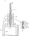
图1是表示本发明的第1实施方式的带针医疗器具的结构的剖视图。Fig. 1 is a cross-sectional view showing the structure of a medical device with needles according to a first embodiment of the present invention.
图2是表示本发明的第1实施方式的带针医疗器具的组装前的状态的剖视图。2 is a cross-sectional view showing a state before assembly of the needle-equipped medical device according to the first embodiment of the present invention.
图3是表示本发明的第1实施方式的变形例的带针医疗器具的结构的剖视图。3 is a cross-sectional view showing the structure of a medical device with needles according to a modification of the first embodiment of the present invention.
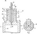
图4是表示本发明的第2实施方式的带针医疗器具的结构的剖视图。4 is a cross-sectional view showing the structure of a medical device with needles according to a second embodiment of the present invention.
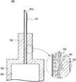
图5是表示本发明的第2实施方式的带针医疗器具的组装前的状态的剖视图。5 is a cross-sectional view showing a state before assembly of the needle-equipped medical device according to the second embodiment of the present invention.
图6是表示以往例中的带针医疗器具的结构的剖视图及其重要部分的放大图。Fig. 6 is a cross-sectional view showing the structure of a medical device with a needle in a conventional example and an enlarged view of important parts thereof.
具体实施方式Detailed ways
以下,参照图1~图5说明本发明的带针医疗器具的实施方式例。另外,在各个附图中,对共同的构件标注了相同的附图标记。而且,本发明并不限定于以下实施方式。Hereinafter, embodiments of the needle-equipped medical device of the present invention will be described with reference to FIGS. 1 to 5 . In addition, in each drawing, the same code|symbol is attached|subjected to a common member. Furthermore, the present invention is not limited to the following embodiments.
另外,按照以下顺序进行说明。In addition, description will be given in the following order.
1.第1实施方式:带针医疗器具1. First Embodiment: Medical Device with Needle
1-1.带针医疗器具的结构例1-1. Structural examples of medical devices with needles
1-2.带针医疗器具的组装方法1-2. How to assemble medical devices with needles
1-3.变形例1-3. Modifications
2.第2实施方式:带针医疗器具2. Second Embodiment: Medical Device with Needle
2-1.带针医疗器具的结构例2-1. Structural examples of medical devices with needles
2-2.带针医疗器具的组装方法2-2. How to assemble medical devices with needles
<1.第1实施方式:带针医疗器具><1. First Embodiment: Medical Device with Needle>
图1是表示本发明的第1实施方式的带针医疗器具1的结构的剖视图,图2是表示带针医疗器具1的组装前的状态的剖视图。在本实施方式例中,作为带针医疗器具1,以预先填充有药液的预充式注射器为例进行说明。FIG. 1 is a cross-sectional view showing the structure of a medical device with
[1-1.带针医疗器具的结构例][1-1. Structural example of medical device with needle]
如图1所示,本实施方式例的带针医疗器具1包括针管6、保持针管6的针设置部2、密封构件5以及具有能够保持药剂的液室10的液体容纳部3。As shown in FIG. 1 , the needle-equipped
作为针管6,使用ISO医疗用针管标准(ISO9626:1991/Amd.1:2001(E))中10~36口径尺寸(ゲージのサイズ)(外径:φ3.4mm~0.1mm)的针管,优选的是使用14~33口径(外径:φ1.6mm~0.2mm)的针管。在针管6的一端设有具有刃面的针尖6a。以下,将针管6的在轴向上与该针尖6a相反一侧的另一端称作基端部6b。As the
作为针管6的材料,例如能够列举出不锈钢,但是并不限定于此,能够使用铝、铝合金、钛、钛合金及其他金属。另外,作为针管6不仅能够应用直形针,而且能够应用至少一部分成为锥形构造的锥形针。作为锥形针,只要与针顶端部相比基端部具有较大的直径,并将其中间部分设为锥形构造即可。另外,针管6的截面形状不仅可以是圆形,也可以是三角形等多边形。The material of the
另外,如图1的放大图所示,在针管6的表面形成有微小的缺口(以下为槽口部7)。该槽口部7是在组装状态下为了增大密封构件5与针管6之间的摩擦力而形成的。后面详细说明其情况。In addition, as shown in the enlarged view of FIG. 1 , minute notches (hereinafter referred to as notches 7 ) are formed on the surface of the
密封构件5由圆柱状的弹性构件构成,在轴心处形成有供针管6贯穿的贯通孔8。该贯通孔8的直径形成得比针管6的外径小。另外,为了使组装容易而在密封构件5的表面涂布有硅油。The sealing
在该密封构件5的贯通孔8内,在组装状态下,以使针尖6a突出于一端、使与针尖6a相反一侧的基端部6b突出于另一端的状态贯穿有针管6,环绕并保持针管6的中心部。由于贯通孔8构成为直径比针管6的外径小,因此在组装状态下,若针管6的基端部6b侧贯穿于贯通孔8,则密封构件5在其弹性力的作用下液密地保持在针管6的外表面。In the through
而且,由于如上所述在针管6的表面形成有槽口部7,因此如图1的放大图所示,密封构件5进入槽口部7而被固定。由此,针管6与密封构件5之间的摩擦力增大,针管6被密封构件5牢固地固定。另外,此时,由于密封构件5被覆槽口部7,因此保持了针管6与密封构件5之间的液密性。Furthermore, since the notch 7 is formed on the surface of the
作为密封构件5的材质,为了使密封构件5与针管6之间的液密性以及密封构件5与针设置部2之间的液密性良好而由弹性材料构成密封构件5,例如可以使用天然橡胶、丁基橡胶、异戊二烯橡胶、丁二烯橡胶、苯乙烯-丁二烯橡胶、硅橡胶、异乙烯橡胶这样的各种橡胶材料、聚氨酯类、聚酯类、聚酰胺类、烯烃类、苯乙烯类等各种热塑性弹性体、或者这些材料的混合物等弹性材料。As the material of the sealing
液体容纳部3在预充式注射器中构成供药剂填充的针筒(外筒)。液体容纳部3形成为在一端具有底部3a、另一端开口的有底筒状,由底部3a和设于开口侧的未图示的密封垫围成的空间形成为供药剂填充的液室10。在液体容纳部3的底部3a的中心形成有与后述的针设置部2的筒孔14相连通的通液孔9。该通液孔9的直径形成为比针管6的基端部6b的外径小的直径。The
针设置部2具有比液体容纳部3的外径小的外径,形成为从液体容纳部3的底部3a的与面对液室10一侧相反的一侧的面向垂直方向突出的筒状,与液体容纳部3形成为一体。作为针设置部2和液体容纳部3的材质,能够列举出聚氯乙烯、聚乙烯、聚丙烯、环状聚烯烃、聚苯乙烯、聚-(4-甲基戊烯-1)、聚碳酸酯、丙烯酸类树脂、丙烯腈-丁二烯-苯乙烯共聚物、聚对苯二甲酸乙二醇酯等聚酯、丁二烯-苯乙烯共聚物、聚酰胺(例如尼龙6、尼龙6·6、尼龙6·10、尼龙12)这样的各种树脂。其中,出于成形容易这方面考虑,优选的是使用聚丙烯、环状聚烯烃、聚酯、聚-(4-甲基戊烯-1)这样的树脂。另外,为了确保内部的可视性,液体容纳部3的材质优选的是实质上透明的材质。The
针设置部2具有对被保持于密封构件5的针管6进行保持的筒孔14,在组装状态下,以密封构件5与筒孔14的内表面相抵接的状态将密封构件5设置于针设置部2。而且,密封构件5被压缩保持在针设置部2的筒孔14内,并且以使能够穿刺生物体的针尖6a突出于一端的状态保持针管6。该筒孔14从针设置部2的一端侧到另一端侧构成有插入口13、密封构件固定孔12以及针插入孔11,与形成于液体容纳部3的底部3a的通液孔9相连通。The
插入口13成为在组装时供保持于密封构件5的针管6插入的部分,插入口13的直径φ4形成为能够压入密封构件5的直径。另外,插入口13的直径φ4形成得比后述的密封构件固定孔12的直径φ1小。由此,在组装状态下,密封构件5在插入到密封构件固定孔12内之后,被突出了插入口13的直径φ4与密封构件固定孔12的直径φ1的差值量而形成的突出部2a卡定,被固定为不会脱落。The
密封构件固定孔12构成在针设置部2的中间部,在组装状态下,成为压缩并保持密封构件5的部分。密封构件固定孔12的直径φ1形成得比组装前的密封构件5的外径φ5小,密封构件固定孔12的轴向的长度形成为与密封构件5的轴向的长度大致相同的长度。The sealing
针插入孔11成为在组装时供从密封构件5的另一端突出的针管6的基端部6b插入的部分,针插入孔11的直径φ2形成为比针管6的基端部6b的外径稍微大的直径。另外,针插入孔11的深度形成得与从密封构件5的另一端突出的针管6的基端部6b的突出长度大致相同。The
密封构件固定孔12的直径φ1形成得比组装前的密封构件5的外径φ5小。因此,在保持针管6的密封构件5插入到筒孔14内的情况下,密封构件5以被压缩的状态容纳于密封构件固定孔12内。由此,产生密封构件5与针管6之间的摩擦力,针管6被固定于密封构件5。而且,由于通过压缩密封构件5而在密封构件5产生弹性力,因此针设置部2与密封构件5之间的液密性提高,并且密封构件5与针管6之间的液密性提高。The diameter φ1 of the sealing
而且,在组装状态下,通过使针管6的基端部6b插入到针插入孔11,从而针管6与液体容纳部3的液室10经由通液孔9相连通。由于通液孔9的直径φ3小于针管6的基端部6b的外径,因此针管6不会向液室10内突出。In the assembled state, by inserting the
另外,在本实施方式例中,φ1设为1.2mm~10mm,更优选设为2mm~5mm。另外,φ2设为0.13mm~3.7mm,更优选设为0.15mm~3.5mm。φ3设为0.07mm~3.37mm,优选设为0.09mm~3.2mm。φ4设为0.8mm~9mm,更优选设为1.0mm~4mm。φ5设为1.3mm~12mm,更优选设为2.1mm~8mm。In addition, in this embodiment example, φ1 is set to 1.2 mm to 10 mm, more preferably 2 mm to 5 mm. In addition, φ2 is set to 0.13 mm to 3.7 mm, more preferably 0.15 mm to 3.5 mm. φ3 is set to 0.07 mm to 3.37 mm, preferably 0.09 mm to 3.2 mm. φ4 is set to 0.8 mm to 9 mm, more preferably 1.0 mm to 4 mm. φ5 is 1.3 mm to 12 mm, more preferably 2.1 mm to 8 mm.
[1-2.带针医疗器具的组装方法][1-2. How to assemble medical devices with needles]
接着,说明具有如上所述的结构的带针医疗器具1的组装方法。Next, a method of assembling the needle-equipped
首先,向密封构件5的贯通孔8贯穿针管6,在使针管6的能够穿刺生物体的针尖6a突出于密封构件5的一端、使针管6的基端部6b突出于密封构件5的另一端的状态下利用密封构件5保持针管6的中间部。First, the
接着,将由密封构件5保持的针管6从其基端部6b侧压入针设置部2的筒孔14内。由于针设置部2的插入口13的直径φ4小于组装前的密封构件5的外径φ5,因此在插入密封构件5时,密封构件5以直径缩小的状态进行压入。此时,由于在密封构件5表面涂布有硅油,因此能够顺滑地进行密封构件5的插入。然后,针管6的基端部6b插入到针设置部2的针插入孔11,在到达通液孔9的端面的时刻,针管6向针设置部2的插入完成。Next, the
然后,如图1所示,在保持着针管6的密封构件5插入到针设置部2之后,向液体容纳部3的液室10内填充期望的药剂,之后封入密封垫,从而本实施方式例的带针医疗器具(预充式注射器)1完成。Then, as shown in FIG. 1, after the sealing
另外,作为能够填充于本实施方式例的带针医疗器具1中的药剂,只要是作为普通注射剂来使用的药剂即可,可以是任意药剂,例如能够列举出抗体等的蛋白质性医药品、激素等的肽性医药品、核酸医药品、细胞医药品、血液制剂、预防各种传染病的疫苗、抗癌药剂、麻醉药、麻药、抗生素、类固醇剂、蛋白酶抑制剂、肝磷酯、葡萄糖等糖质注射液、氯化钠、乳酸钾等电解质补充用注射液、维生素剂、脂肪乳剂、造影剂等。In addition, as the drug that can be filled in the medical device with
在本实施方式例中,通过利用密封构件5保持针管6,并且将保持着针管6的密封构件5压缩并保持于针设置部2,从而能够使针管6与密封构件5之间产生摩擦力,能够将针管6固定于针设置部2。由此,针管6不会从针设置部2脱落。而且,通过从针设置部2对密封构件5施加压缩力,从而由弹性构件构成的密封构件5产生弹性力,因此针设置部2与密封构件5之间的液密性以及密封构件5与针管6之间的液密性提高。由此,填充到液室10内的药剂不会向外部漏出。In this embodiment example, by holding the
另外,在本实施方式例中,由于针设置部2与针管6之间的固定未使用粘接剂,因此填充到液体容纳部3内的药剂不会直接与粘接剂接触。因此,不会产生由粘接剂的混入对药剂带来的不良影响。而且,由于针设置部2与针管6之间的固定也未使用高频熔接,因此如图6所示,不会产生由气泡引起的龟裂,也不会产生漏液。由此,谋求提高了带针医疗器具1的使用时的可靠性。In addition, in the present embodiment, since no adhesive is used for fixing the
另外,在本实施方式例中,由于在针管6形成有槽口部7,密封构件5进入槽口部7,因此针管6与密封构件5之间的摩擦力进一步提高,针管6的固定变得更加牢固。在本实施方式例中,设为为了提高针管6与密封构件5之间的摩擦力而在针管6形成槽口部7的例子,但是此外,也可以通过对针管6的表面实施粗糙面加工而形成微小的凹凸部来提高针管6与密封构件5之间的摩擦力。In addition, in this embodiment, since the
另外,在本实施方式例中,通过将通液孔9的直径φ3设为比针管6的基端部6b外径小的直径,从而在从针管6的针尖6a侧向基端部6b方向的力施加到针管6时,能够防止针管6向液室10侧后退。在使用带针医疗器具1的情况下,在针管6刺入皮肤、血管时施加于针管6的压入力比在从皮肤、血管中拔出针管6时对针管6产生的拉拔力大。通过将通液孔9的直径φ3设为比针管6的基端部6b的外径小的直径,从而即使在将针管6刺入皮肤、血管时产生的针管6与密封构件5之间的摩擦力非常小(或者没有摩擦力)的情况下,也能够使针管6穿刺生物体。In addition, in this embodiment example, by setting the diameter φ3 of the
另外,在本实施方式例中,通过将通液孔9的直径φ3设为比针管6的基端部6b的外径小的直径,从而针管6未向液室10内突出。因此,在液室10内,当使密封垫移动并排出药剂时,能够使密封垫移动至密封垫与液体容纳部3的底部3a相抵接,能够减少液室10内的残液。In addition, in this embodiment, the
另外,做成了在密封构件5的轴心形成由直径比针管6的外径小的孔构成的贯通孔8的结构,但是也可以做成利用狭缝构成贯通孔8、使针管6贯通该狭缝的结构。即,形成于密封构件5的贯通孔8只要是能够供针管6贯穿、并且能够紧密接触并保持针管6的结构即可。在作为贯通孔8形成了狭缝的情况下,当贯穿针管6时,在从外周侧按压密封构件5而使狭缝扩大之后插入针管6,从而能够容易地使针管6贯穿于密封构件5。In addition, the through-
[1-3.变形例][1-3. Modifications]
在本实施方式例中,作为带针医疗器具1以预充式注射器为例进行了说明,但是也可以做成将安装于供血液、医疗溶剂药剂流动的管的顶端的针管安装在本发明的带针医疗器具上的结构。In this embodiment example, a prefilled syringe has been described as an example of a medical device with a
在图3中表示第1实施方式的变形例的带针医疗器具20的剖视图。在图3中,对与图1对应的部分标注相同的附图标记并省略重复说明。FIG. 3 shows a cross-sectional view of a medical device with needles 20 according to a modified example of the first embodiment. In FIG. 3 , parts corresponding to those in FIG. 1 are denoted by the same reference numerals and repeated descriptions are omitted.
在变形例的带针医疗器具20中,液体容纳部21构成为与连接于输液袋(未图示)等的软管22相连的连接部。In the medical device with needle 20 according to the modified example, the
液体容纳部21形成为在一端具有底部21a、另一端开口的有底筒状,在开口的另一端的外周以紧密接触的方式嵌入有由弹性体构成的软管22。这种结构能够适用于留置针、采血针。The
在变形例的带针医疗器具20中,液体容纳部21的轴向的长度只要是能够使所接合的管22稳定地保持在液体容纳部主体21的外周面上的长度即可。In the medical device with needle 20 of the modified example, the axial length of the
如变形例所示,在具有安装于软管22的顶端的针管6的带针医疗器具20中,针管6也借助于与由弹性构件形成的密封构件5之间的摩擦力而固定,并且借助于密封构件5所产生的弹性力而液密地保持于针设置部2。而且,在变形例的带针医疗器具20中,由于针设置部2与针管6之间的固定也不需要粘接剂、高频熔接,因此不会对药剂产生不良影响,也能够防止漏液。As shown in the modified example, in the needled medical device 20 having the
<2.第2实施方式><2. Second Embodiment>
接着,说明本发明的第2实施方式的带针医疗器具30。图4的(A)是表示本发明的第1实施方式例的带针医疗器具1的结构的剖视图,图4的(B)是图4的(A)的沿a-a’线的剖视图。另外,图5的(A)是带针医疗器具1的组装前的剖视图,图5的(B)是图5的(A)的沿b-b’线的剖视图。本实施方式例的带针医疗器具30是针设置部的结构与第1实施方式不同的例子。在图4和图5中,对与图1对应的部分标注相同的附图标记并省略重复说明。在本实施方式例中,作为带针医疗器具30也以预充式注射器为例进行说明。Next, a medical device with
[2-1.带针医疗器具的结构][2-1. Structure of medical devices with needles]
如图4的(A)所示,本实施方式例的带针医疗器具30包括针管6、保持针管6的针设置部32、密封构件5以及具有能够保持药剂的液室10的液体容纳部3。而且,针设置部32包括支承台33、夹持部39以及盖部35。As shown in FIG. 4(A), the needle-equipped
支承台33设置在液体容纳部3的底部3a的、与液室10相反一侧的面上的中央部,由相对于底部3a的面向垂直方向突出形成的圆柱形状的构件构成。在支承台33的与液体容纳部3侧相反一侧的端面设有供密封构件5的另一端插入并被固定保持的密封构件固定槽38。而且,在该密封构件固定槽38的底面的中心部设有与形成于液体容纳部3的底部3a的通液孔9相连通、并固定保持针管6的基端部6b的针插入孔37。The
密封构件固定槽38的直径形成得比组装前的密封构件5的外径略小,密封构件固定槽38的深度只要是使密封构件5的另一端进入一部分而固定的程度的深度即可。作为密封构件固定槽38的深度,只要是3mm~15mm左右即可,例如能够设为8mm。另外,针插入孔37的直径形成为比针管6的基端部6b的直径略大、能够供针管6的基端部6b插入的直径,针插入孔37的深度形成得与从密封构件5的另一端突出的针管6的基端部6b的突出长度相同。作为针插入孔37的直径,若将针管6的外径设为φ6,则只要是φ6+0.03mm~φ6+0.3mm左右即可,例如能够设为φ6+0.05mm。The diameter of the sealing
夹持部39从支承台33的与液体容纳部3侧相反一侧的端面向与该端面垂直的方向突出地形成,由在环绕密封构件固定槽38的周围形成为多个(在图4和图5中为四个)的柱状的夹持部主体34构成。夹持部主体34形成为沿轴向分割圆筒状的构件而成的形状,在环绕密封构件固定槽38的周围呈圆周状等间隔地配置。在组装状态下,保持着针管6的密封构件5插入到由四个夹持部主体34围成的区域内,利用四个夹持部主体34夹持密封构件5。The clamping
在组装前,由四个夹持部主体34构成的夹持部39的内径构成为与组装前的密封构件5的外径相同或者比组装前的密封构件5的外径小。另外,夹持部主体34的高度构成为,从密封构件固定槽38的底面到夹持部主体34的顶端的高度与密封构件5的轴向的长度大致相同。而且,在夹持部主体34的与夹持密封构件5一侧相反的一侧的侧面,从支承台33侧到夹持部主体34的轴向的中间部形成有向半径外方向突出的凸部34a。Before assembly, the inner diameter of the clamping
盖部35由在一端具有底部35a、另一端开口的有底筒状的构件构成,在底部35a的中心部形成有能够供针管6贯穿的贯通孔36。盖部35的从开口的端面到底部35a的深度构成为与夹持部主体34的距支承台33的高度相同。在盖部35的内周面,从开口侧到中间部形成有向半径内方突出形成的缩径部35b。在组装前,形成有缩径部35b的位置处的盖部35的内径形成为比形成有凸部34a的位置处的夹持部39的外径小的直径。The
在组装状态下,如图4的(A)、图4的(B)所示,盖部35以其缩径部35b与夹持部主体34的凸部34a相抵接的方式嵌入。在组装前,缩径部35b处的盖部35的内径形成得比形成有凸部34a的位置处的夹持部39的外径小,因此,若盖部35与夹持部39嵌合,则各个夹持部主体34被向密封构件5侧按压。由此,在密封构件5上产生来自外周面的压缩力,因此组装状态下的密封构件5的外径φa小于嵌合盖部35之前的密封构件5的外径φb。In the assembled state, as shown in FIG. 4(A) and FIG. 4(B) , the
另外,虽然在图4的(A)中省略了图示,但是在本实施方式例中也与第1实施方式同样地在针管6的表面形成有槽口部,谋求提高密封构件5与针管6之间的摩擦力。In addition, although not shown in (A) of FIG. 4 , in this embodiment, a notch is formed on the surface of the
[2-2.带针医疗器具的组装方法][2-2. How to assemble medical devices with needles]
接着,说明具有如上所述的结构的带针医疗器具1的组装方法。Next, a method of assembling the needle-equipped
首先,向密封构件5的贯通孔8内贯穿针管6,在使针管6的能够穿刺生物体的针尖6a突出于密封构件5的一端、使针管6的基端部6b突出于密封构件5的另一端的状态下利用密封构件5保持针管6的中间部。First, the
然后,将由密封构件5保持着的针管6从夹持部39的顶端侧插入到由夹持部主体34围成的区域内。Then, the
在此,在组装前,由多个夹持部主体34构成的夹持部39的内径构成为与组装前的密封构件5的外径相同或者比组装前的密封构件5的外径小,但是由于各个夹持部主体34形成为柱状,因此易于向半径外方向挠曲。因此,能够向由夹持部主体34围成的区域内顺滑地插入密封构件5。此外,由于在密封构件5表面涂布有硅油,因此能够顺滑地进行密封构件5的插入。Here, before assembly, the inner diameter of the clamping
然后,将针管6的基端部6b插入到针插入孔379内,并且将密封构件5的另一端压入到密封构件固定槽38内。由于通液孔9的直径形成为比针管6的基端部6b的外径小的直径,因此在针管6的基端部6b到达通液孔9的端面的时刻,针管6向夹持部39的插入停止。Then, the
此时,由于密封构件固定槽38的直径形成为比组装前的密封构件5的直径略小的直径,因此密封构件5的另一端被压缩并插入到密封构件固定槽38内。因此,密封构件5在密封构件5的弹性力的作用下以一定程度固定并保持在密封构件固定槽38内。At this time, since the diameter of the sealing
之后,使盖部35以将夹持部39从盖部35的开口侧嵌入的方式移动,使针管6的针尖6a贯穿于底部35a的贯通孔36,并且使盖部35的开口侧的端面与支承台33的端面相抵接。由此,盖部35以盖部35的缩径部35b与夹持部主体34的凸部34a相抵接的方式与夹持部39相嵌合。Afterwards, the
在此,盖部35与夹持部39嵌合时的固定能够通过在盖部35的内周形成外螺纹、在夹持部39的与面对密封构件5一侧相反的一侧的侧面形成内螺纹并使两者螺纹连接来进行。此外,也可以通过在盖部35的内周形成卡定爪并进行卡定来进行,该卡定爪能够卡定于夹持部39的与面对密封构件5一侧相反的一侧的侧面。另外,盖部35与夹持部39之间的固定也可以利用粘接剂来进行,但是为了避免粘接剂混入到容纳于液室10的药剂,优选的是通过螺纹连接或卡定来进行。Here, the fixing when the
然后,在盖部35与夹持部39嵌合连接之后,与第1实施方式同样地向液体容纳部3的液室10内填充期望的药剂,之后封入密封垫,从而本实施方式例的带针医疗器具(预充式注射器)30完成。Then, after the
在本实施方式例中,由于构成夹持部39的夹持部主体34形成为柱状,因此与圆筒状等相比易于挠曲。因而,各个夹持部主体34易于向半径外方向扩展,因此在将保持着针管6的密封构件5插入到由夹持部主体34围成的区域内时,能够以对密封构件5施加的压缩力较低的状态插入密封构件5。而且,在嵌合了盖部35的情况下,夹持部主体34向与密封构件5接触的一侧挠曲,因此能够压缩密封构件5。In this embodiment example, since the clamping part
在本实施方式例中,盖部35嵌合于夹持部39,从而在夹持部39被向密封构件5侧按压的状态下固定,因此对密封构件5施加有压缩力。由此,针管6与密封构件5之间的摩擦力增大,在该摩擦力的作用下,针管6被固定于密封构件5。另外,通过对密封构件5施加有压缩力,从而密封构件5产生弹性力。因此,密封构件5与针管6以及密封构件5与夹持部39之间的液密性提高,填充到液体容纳部3内的药剂不会向外部漏出。In the present embodiment, since the
另外,在本实施方式例中,密封构件5的另一端侧插入到支承台33的密封构件固定槽38内并被固定。因此,密封构件5的靠近液体容纳部3的部分处的液密性进一步提高,因此漏液防止效果进一步提高。In addition, in this embodiment example, the other end side of the sealing
此外,能够获得与第1实施方式同样的效果。In addition, the same effect as that of the first embodiment can be obtained.
在本实施方式例中,在夹持部主体34形成了凸部34a,在盖部35形成了缩径部35b,但只要是在盖部35与夹持部39嵌合时夹持部39向密封构件5侧进行按压的结构即可,能够进行各种变更。例如,也能够设为将夹持部主体34的侧面或盖部35的内周面形成为锥状、在盖部35与夹持部39嵌合时夹持部39向密封构件5侧按压的结构。In the present embodiment, the
而且,本实施方式例的带针医疗器具30也与第1实施方式的变形例同样地能够适用于安装在供医疗用药剂、血液流动的管的顶端进行使用的带针医疗器具。在该情况下,能够获得与第1实施方式的变形例同样的效果。Furthermore, the needle-equipped
以上,在本发明的带针医疗器具的实施方式例中,也包括对其作用效果进行的说明。但是,本发明的带针医疗器具并不限定于上述实施方式例,在不脱离权利要求书所记载的发明主旨的范围内能够实施各种变形。In the above, the description of the operation and effect of the embodiment of the medical device with needles of the present invention is also included. However, the medical device with needles of the present invention is not limited to the above-mentioned embodiments, and various modifications can be made within the range not departing from the gist of the invention described in the claims.
产业上的可利用性Industrial availability
本发明能够应用于注射器、留置针等以及其他带针医疗器具。The present invention can be applied to syringes, indwelling needles, and other medical devices with needles.
附图标记说明Explanation of reference signs
1、20、30…带针医疗器具;2、32…针设置部;2a…突出部;3、21…液体容纳部;3a…底部;5…密封构件;6…针管;6a…针尖;6b…基端部;7…槽口部;8…贯通孔;9…通液孔;10…液室;11…针插入孔;12…密封构件固定孔;13…插入口;14…筒孔;22…软管;33…支承台;34…夹持部主体;35…盖部;35a…底部;35b…缩径部;36…贯通孔;37…针插入孔;38…密封构件固定槽;39…夹持部。1, 20, 30...Medical device with needle; 2, 32...Needle installation part; 2a...Protruding part; 3, 21...Liquid storage part; 3a...Bottom part; ...base end; 7...notch; 8...through hole; 9...liquid hole; 10...liquid chamber; 11...needle insertion hole; 12...sealing member fixing hole; 13...insertion port; 14...cylinder hole; 22...hose; 33...support base; 34...clamping part main body; 35...cover; 35a...bottom; 35b...reduced diameter part; 36...through hole; 37...needle insertion hole; 39...clamping part.
Claims (5)
Applications Claiming Priority (3)
| Application Number | Priority Date | Filing Date | Title |
|---|---|---|---|
| JP2010215363 | 2010-09-27 | ||
| JP2010-215363 | 2010-09-27 | ||
| PCT/JP2011/070211WO2012043162A1 (en) | 2010-09-27 | 2011-09-06 | Medical instrument with attached needle |
Publications (1)
| Publication Number | Publication Date |
|---|---|
| CN103153374Atrue CN103153374A (en) | 2013-06-12 |
Family
ID=45892635
Family Applications (1)
| Application Number | Title | Priority Date | Filing Date |
|---|---|---|---|
| CN2011800466063APendingCN103153374A (en) | 2010-09-27 | 2011-09-06 | Medical instrument with needle |
Country Status (5)
| Country | Link |
|---|---|
| US (1) | US20130197452A1 (en) |
| EP (1) | EP2623148A1 (en) |
| JP (1) | JPWO2012043162A1 (en) |
| CN (1) | CN103153374A (en) |
| WO (1) | WO2012043162A1 (en) |
Cited By (2)
| Publication number | Priority date | Publication date | Assignee | Title |
|---|---|---|---|---|
| CN105530979A (en)* | 2013-09-11 | 2016-04-27 | 泰尔茂株式会社 | Medical hollow needle assembly and method for manufacturing hollow needle |
| CN112076363A (en)* | 2019-06-13 | 2020-12-15 | 肖特瑞士股份公司 | Container prefillable or prefillable with fluid, needle cannula assembly and closure system therefor |
Families Citing this family (4)
| Publication number | Priority date | Publication date | Assignee | Title |
|---|---|---|---|---|
| US10279124B2 (en) | 2015-01-22 | 2019-05-07 | Aesynt Incorporated | Expanding needle device and method of expansion for the transfer of fluids |
| JP2016163642A (en)* | 2015-03-06 | 2016-09-08 | 大成化工株式会社 | Barrel with needle and syringe having the same |
| JP2019180835A (en)* | 2018-04-10 | 2019-10-24 | デンカ生研株式会社 | Injection needle formation body and hollow needle for injection |
| CN115922320B (en)* | 2022-11-25 | 2025-08-01 | 苏州凌稳智能装备有限公司 | Nine-needle suction needle assembling device for medical cosmetology |
Citations (4)
| Publication number | Priority date | Publication date | Assignee | Title |
|---|---|---|---|---|
| JPH0767960A (en)* | 1993-08-31 | 1995-03-14 | Showa Yakuhin Kako Kk | Injecting tool |
| JPH08117334A (en)* | 1994-10-25 | 1996-05-14 | Nissho Corp | Kit for mixing |
| JP2004154210A (en)* | 2002-11-05 | 2004-06-03 | Enomoto Co Ltd | Medical device, animal treatment device, and method of manufacturing the same |
| CN2678666Y (en)* | 2003-11-26 | 2005-02-16 | 吕海洋 | Disposable self-destroying safety syringe |
Family Cites Families (12)
| Publication number | Priority date | Publication date | Assignee | Title |
|---|---|---|---|---|
| US4240425A (en)* | 1978-10-23 | 1980-12-23 | American Hospital Supply Corporation | Syringe with plug type needle hub lock |
| KR930003314B1 (en)* | 1984-11-21 | 1993-04-26 | 에발트 픽크하르트 | syringe |
| US5286258A (en)* | 1991-03-08 | 1994-02-15 | Habley Medical Technology Corporation | Multipharmaceutical delivery system |
| AU682670B2 (en)* | 1993-02-05 | 1997-10-16 | Becton Dickinson & Company | Syringe needle isolation device |
| US5395337A (en)* | 1993-08-31 | 1995-03-07 | Clemens; Anton H. | Needle retraction system |
| US5810785A (en)* | 1996-08-19 | 1998-09-22 | Johnson & Johnson Medical, Inc. | Blown-in-place blood gasket for a safety catheter |
| JP4187922B2 (en)* | 2000-09-14 | 2008-11-26 | テルモ株式会社 | Liquid injection needle and liquid injection device |
| US6387078B1 (en)* | 2000-12-21 | 2002-05-14 | Gillespie, Iii Richard D. | Automatic mixing and injecting apparatus |
| TWI243065B (en)* | 2004-06-11 | 2005-11-11 | Ming-Jeng Shiu | Injector with a retractable needle body |
| EP1621565A1 (en)* | 2004-07-28 | 2006-02-01 | Cytec Surface Specialties Austria GmbH | Epoxy resins with improved elasticity |
| EP1776925A1 (en)* | 2005-10-20 | 2007-04-25 | Roche Diagnostics GmbH | Analyzing means with lancet and test element |
| DE102007023129A1 (en)* | 2007-05-16 | 2008-11-20 | Raumedic Ag | A process for the production of a plastic product with a plastic hard component and a plastic soft component as well as plastic product produced by the process |
- 2011
- 2011-06-09USUS13/825,981patent/US20130197452A1/ennot_activeAbandoned
- 2011-09-06JPJP2012536304Apatent/JPWO2012043162A1/ennot_activeWithdrawn
- 2011-09-06EPEP11828723.4Apatent/EP2623148A1/ennot_activeWithdrawn
- 2011-09-06CNCN2011800466063Apatent/CN103153374A/enactivePending
- 2011-09-06WOPCT/JP2011/070211patent/WO2012043162A1/enactiveApplication Filing
Patent Citations (4)
| Publication number | Priority date | Publication date | Assignee | Title |
|---|---|---|---|---|
| JPH0767960A (en)* | 1993-08-31 | 1995-03-14 | Showa Yakuhin Kako Kk | Injecting tool |
| JPH08117334A (en)* | 1994-10-25 | 1996-05-14 | Nissho Corp | Kit for mixing |
| JP2004154210A (en)* | 2002-11-05 | 2004-06-03 | Enomoto Co Ltd | Medical device, animal treatment device, and method of manufacturing the same |
| CN2678666Y (en)* | 2003-11-26 | 2005-02-16 | 吕海洋 | Disposable self-destroying safety syringe |
Cited By (2)
| Publication number | Priority date | Publication date | Assignee | Title |
|---|---|---|---|---|
| CN105530979A (en)* | 2013-09-11 | 2016-04-27 | 泰尔茂株式会社 | Medical hollow needle assembly and method for manufacturing hollow needle |
| CN112076363A (en)* | 2019-06-13 | 2020-12-15 | 肖特瑞士股份公司 | Container prefillable or prefillable with fluid, needle cannula assembly and closure system therefor |
Also Published As
| Publication number | Publication date |
|---|---|
| US20130197452A1 (en) | 2013-08-01 |
| WO2012043162A1 (en) | 2012-04-05 |
| JPWO2012043162A1 (en) | 2014-02-06 |
| EP2623148A1 (en) | 2013-08-07 |
Similar Documents
| Publication | Publication Date | Title |
|---|---|---|
| EP3275482B1 (en) | Syringe holder and medical solution administration set | |
| US4664655A (en) | High viscosity fluid delivery system | |
| AU603557B2 (en) | Power syringe with volume reducing adapter | |
| US4758234A (en) | High viscosity fluid delivery system | |
| US20110282298A1 (en) | Device for injecting fluid isolated from microneedle hub with dead-space-reducing insert | |
| US6003566A (en) | Vial transferset and method | |
| JP6731909B2 (en) | Packaging and packaging assembly | |
| CN103153374A (en) | Medical instrument with needle | |
| US9808584B2 (en) | Elastic cap and syringe assembly therewith | |
| US9757526B2 (en) | Drug administration instrument | |
| WO2012043161A1 (en) | Medical instrument with attached needle | |
| EP3437681B1 (en) | Medicine administering apparatus, method of using medicine administering apparatus, and method for manufacturing medicine administering apparatus | |
| JPWO2018168989A1 (en) | Medical solution administration system | |
| JP2018093906A (en) | Liquid medicine injection device and injection needle used for the device | |
| US20190022326A1 (en) | Seal member, syringe assembly, and prefilled syringe | |
| JP6014395B2 (en) | Drug micro-administration device | |
| JP2012055441A (en) | Medicine injection device | |
| WO2013145998A1 (en) | Liquid administration set | |
| JP5897125B2 (en) | Liquid dosing device | |
| WO2013146049A1 (en) | Liquid administration device | |
| JP2014018352A (en) | Trace medicine administration instrument |
Legal Events
| Date | Code | Title | Description |
|---|---|---|---|
| C06 | Publication | ||
| PB01 | Publication | ||
| C10 | Entry into substantive examination | ||
| SE01 | Entry into force of request for substantive examination | ||
| C02 | Deemed withdrawal of patent application after publication (patent law 2001) | ||
| WD01 | Invention patent application deemed withdrawn after publication | Application publication date:20130612 |