CN103148937A - Real-time on-track spectrum scaling device and method - Google Patents
Real-time on-track spectrum scaling device and methodDownload PDFInfo
- Publication number
- CN103148937A CN103148937ACN2013100395340ACN201310039534ACN103148937ACN 103148937 ACN103148937 ACN 103148937ACN 2013100395340 ACN2013100395340 ACN 2013100395340ACN 201310039534 ACN201310039534 ACN 201310039534ACN 103148937 ACN103148937 ACN 103148937A
- Authority
- CN
- China
- Prior art keywords
- calibration
- spectral
- imaging
- area
- orbit
- Prior art date
- Legal status (The legal status is an assumption and is not a legal conclusion. Google has not performed a legal analysis and makes no representation as to the accuracy of the status listed.)
- Pending
Links
Images


Landscapes
- Spectrometry And Color Measurement (AREA)
Abstract
Translated fromChinese
Description
Translated fromChinese技术领域:Technical field:
本发明涉及光谱成像领域,具体涉及一种实时在轨光谱定标装置及方法。The invention relates to the field of spectral imaging, in particular to a real-time on-orbit spectral calibration device and method.
背景技术:Background technique:
成像光谱技术在环境监测、矿物探查、地球科学等领域有着广泛应用。要通过星载成像光谱仪获取的数据得到真实、有效的地物光谱信息,必须对仪器进行光谱定标。除了实验室定标之外,考虑到仪器在轨运行时的环境、状态不断改变,因此在轨定标是不可或缺的。Imaging spectroscopy technology has been widely used in environmental monitoring, mineral exploration, earth science and other fields. In order to obtain real and effective ground object spectral information through the data obtained by the spaceborne imaging spectrometer, the spectral calibration of the instrument must be carried out. In addition to laboratory calibration, on-orbit calibration is indispensable considering that the environment and state of the instrument are constantly changing during on-orbit operation.
对于目前广泛应用的色散型成像光谱仪,传统的在轨定标方式包括大气临边定标、太阳定标及内定标等。这些方式都是与成像任务分时完成,因此定标与拍摄有时间差。仪器在执行拍摄任务时,一方面受到太阳光照的影响,整体温度发生变化;另一方面仪器内部的电子学部件工作发热,也使仪器的状态不能保持恒定。所以成像过程中,不同时刻会发生不同的光谱漂移,在成像之前或之后进行光谱定标都会造成状态偏差。For the widely used dispersive imaging spectrometer, the traditional on-orbit calibration methods include atmospheric limb calibration, solar calibration and internal calibration. These methods are completed in time-sharing with the imaging task, so there is a time difference between calibration and shooting. When the instrument is performing shooting tasks, on the one hand, it is affected by the sun’s rays, and the overall temperature changes; on the other hand, the electronic components inside the instrument generate heat, which also makes the state of the instrument unable to maintain a constant state. Therefore, during the imaging process, different spectral drifts will occur at different times, and spectral calibration before or after imaging will cause state deviations.
此外,仪器中还需要设计专门的定标光路,利用运动部件(如扫描镜)在成像模式和定标模式之间进行切换,这样就增加了系统硬件和软件上的复杂度。In addition, a special calibration optical path needs to be designed in the instrument, and moving parts (such as scanning mirrors) are used to switch between imaging mode and calibration mode, which increases the complexity of system hardware and software.
发明内容:Invention content:
本发明提出了一种实时在轨光谱定标装置及方法,解决现有定标装置中存在的无法实时在轨光谱定标问题。The invention provides a real-time on-orbit spectral calibration device and method, which solves the problem that the existing calibration device cannot real-time on-orbit spectral calibration.
一种实时在轨光谱定标装置,如附图1所示,包括积分球1,光谱标准滤光片2、光纤3及探测器4。A real-time on-orbit spectral calibration device, as shown in Figure 1, includes an integrating sphere 1, a spectral
积分球1的出射光经过光谱标准滤光片2后成为定标光,由光纤3引至被标定成像光谱系统5的狭缝两端,定标光射入狭缝,经光谱仪成像在探测器4两侧的定标区4-1上,根据定标区4-1像元的光谱数据,对被标定成像光谱系统5进行光谱定标。The outgoing light of the integrating sphere 1 passes through the spectral
所述积分球1采用小型积分球,直径小于80mm,开口小于30mm,其光源有效发光谱段包含被标定成像光谱系统5的成像谱段。The integrating sphere 1 is a small integrating sphere with a diameter of less than 80 mm and an opening of less than 30 mm. The effective emission spectrum of the light source includes the imaging spectrum of the calibrated
所述光谱标准滤光片2的直径等于积分球开口直径,通光谱段包含被标定成像光谱系统5的成像波段,光谱特性在仪器工作温度范围内保持稳定。The diameter of the spectral
所述光纤3的通光谱段包含被定标成像光谱系统5的成像谱段;The pass spectrum section of the
所述探测器4分为定标区4-1和成像区4-2,定标区4-1位于成像区4-2空间维方向的两端,每端设有1-2列,其像元尺寸为成像区4-2像元尺寸的一半。The
具体定标方法步骤如下:The specific calibration method steps are as follows:
1)仪器在轨运行,完成一次成像任务,探测器4的成像区4-2获得光谱图像数据,两端定标区4-1获得光谱定标数据;1) The instrument is running in orbit and completes an imaging task. The imaging area 4-2 of the
2)根据光谱标准滤光片2的特征峰,确定两端定标区4-1每个像元对应的中心波长;2) According to the characteristic peaks of the spectral
3)设一端定标区4-1像元Ai和另一端定标区4-1像元Bj对应的中心波长相同,则位于其连线上的成像区4-2像元具有与这两个定标区4-1像元相同的中心波长;3) Assuming that the central wavelengths corresponding to the pixel Ai in the calibration area 4-1 at one end and the pixel Bj in the calibration area 4-1 at the other end are the same, then the pixel in the imaging area 4-2 located on the line between them has the same The 4-1 pixels in the two calibration areas have the same central wavelength;
4)按照步骤3)所述方法确定成像区4-2每一行像元对应的中心波长。4) Determine the center wavelength corresponding to each row of pixels in the imaging area 4-2 according to the method described in step 3).
本发明的优点在于:光谱定标与成像同时完成,每帧成像都能获得光谱定标数据,从根本上解决了以往定标与成像时仪器状态不一致的问题,提高了定标数据的有效性。本发明探测器4的定标区4-1设在空间维两侧,针对一般色散成像光谱仪主要存在的位移型及旋转型光谱漂移可以实现高精度定标,如附图2所示。此外,定标区4-1像元尺寸小,因而谱段间隔比成像区4-2小一半,所以能够捕捉更精细的光谱信息。再加上光谱标准滤光片2的光谱特征,进而获得很高的光谱定标精度。使用光纤3以及相对仪器体来说积较小的积分球1和光谱标准滤光片2,避免了单独的定标光路,有效减轻了仪器的体积和复杂度。The advantage of the present invention is that spectral calibration and imaging are completed at the same time, and spectral calibration data can be obtained for each frame of imaging, which fundamentally solves the problem of inconsistency between calibration and imaging in the past, and improves the effectiveness of calibration data . The calibration area 4-1 of the
附图说明:Description of drawings:
附图1为本发明的总框图。Accompanying drawing 1 is general block diagram of the present invention.
附图2为光谱漂移示意图。Accompanying drawing 2 is the schematic diagram of spectral drift.
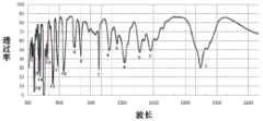
附图3为实施例中光谱标准滤光片的光谱特征图。Accompanying drawing 3 is the spectral feature diagram of spectral standard filter in the embodiment.
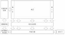
附图4为实施例中探测器的结构示意图。Accompanying drawing 4 is the structure diagram of the detector in the embodiment.
附图5为实施例中CMOS探测器的具体设计框图。Accompanying drawing 5 is the specific design block diagram of CMOS detector in the embodiment.
具体实施方式:Detailed ways:
根据发明内容,本实施例构建了一套用于可见-近红外波段色散型成像光谱仪的实时光谱定标装置,如附图1所示。其中各个部分的具体参数和设计如下:According to the content of the invention, this embodiment constructs a real-time spectral calibration device for a visible-near-infrared band dispersive imaging spectrometer, as shown in FIG. 1 . The specific parameters and design of each part are as follows:
积分球:使用Labsphere公司的小型积分球3P-GPS-030-SF,直径3英寸,出口1英寸;Integrating sphere: use Labsphere's small integrating sphere 3P-GPS-030-SF, with a diameter of 3 inches and an outlet of 1 inch;
光谱标准滤光片:使用美国Avian Technologies公司的WCT-2065,其光谱特性如附图3所示,在400nm~1000nm的可见-近红外范围内有着丰富的光谱特征峰;Spectrum standard filter: use WCT-2065 from Avian Technologies in the United States, its spectral characteristics are shown in Figure 3, and it has rich spectral characteristic peaks in the visible-near infrared range of 400nm~1000nm;
光纤:采用南京春晖科技实业有限公司生产的光纤,波长范围400nm~1000nm。Optical fiber: The optical fiber produced by Nanjing Chunhui Technology Industrial Co., Ltd. is used, and the wavelength range is 400nm~1000nm.
探测器:CMOS探测器,采用下文所述特殊设计。Detector: CMOS detector with special design as described below.
本实施例中CMOS探测器的结构如附图4所示,具体设计框图如附图5所示。探测器通过逻辑控制部分控制行移位寄存器进行移位,选择不同的读出行;控制读出移位寄存器进行移位,逐个输出模拟信号。探测器成像时,每读出一行图像数据,就通过逻辑控制部分控制读出两行定标数据。像元信号经过相关双采样和列放大电路后,由读出口向外输出。The structure of the CMOS detector in this embodiment is shown in Figure 4, and the specific design block diagram is shown in Figure 5. The detector controls the row shift register to shift through the logic control part, and selects different readout rows; controls the readout shift register to shift, and outputs analog signals one by one. When the detector is imaging, each time a line of image data is read out, two lines of calibration data are read out through the control of the logic control part. The pixel signal is output from the readout port after passing through the correlation double sampling and column amplification circuit.
本实施例CMOS探测器成像区的光谱维为64,空间维为512,像元尺寸30μm,谱段间隔10nm;两侧的定标区每行各有2个像元,沿光谱维一列有128个像元,像元尺寸15μm。则一帧图像的大小为512×64,而对应一帧的光谱定标数据大小为(2+2)×128,定标区域的谱段间隔为5nm。The spectral dimension of the imaging area of the CMOS detector in this embodiment is 64, the spatial dimension is 512, the pixel size is 30 μm, and the spectral segment interval is 10 nm; each row of the calibration areas on both sides has 2 pixels, and there are 128 pixels in a column along the spectral dimension. pixels, with a pixel size of 15 μm. Then, the size of one frame of image is 512×64, and the size of spectral calibration data corresponding to one frame is (2+2)×128, and the interval between spectral segments in the calibration region is 5 nm.
本发明可以使用的探测器不仅限于CMOS探测器。采用CCD或红外焦平面器件时,成像区4-2和定标区4-1分别流片,然后拼接封装在同一底座上或杜瓦内。成像区4-2和定标区4-1之间允许存在拼缝。The detectors that can be used in the present invention are not limited to CMOS detectors. When a CCD or an infrared focal plane device is used, the imaging area 4-2 and the calibration area 4-1 are taped out separately, and then spliced and packaged on the same base or in a Dewar. A seam is allowed between the imaging area 4-2 and the calibration area 4-1.
Claims (6)
Translated fromChinesePriority Applications (1)
| Application Number | Priority Date | Filing Date | Title |
|---|---|---|---|
| CN2013100395340ACN103148937A (en) | 2013-01-31 | 2013-01-31 | Real-time on-track spectrum scaling device and method |
Applications Claiming Priority (1)
| Application Number | Priority Date | Filing Date | Title |
|---|---|---|---|
| CN2013100395340ACN103148937A (en) | 2013-01-31 | 2013-01-31 | Real-time on-track spectrum scaling device and method |
Publications (1)
| Publication Number | Publication Date |
|---|---|
| CN103148937Atrue CN103148937A (en) | 2013-06-12 |
Family
ID=48547144
Family Applications (1)
| Application Number | Title | Priority Date | Filing Date |
|---|---|---|---|
| CN2013100395340APendingCN103148937A (en) | 2013-01-31 | 2013-01-31 | Real-time on-track spectrum scaling device and method |
Country Status (1)
| Country | Link |
|---|---|
| CN (1) | CN103148937A (en) |
Cited By (5)
| Publication number | Priority date | Publication date | Assignee | Title |
|---|---|---|---|---|
| CN104458591A (en)* | 2014-12-03 | 2015-03-25 | 中国科学院光电研究院 | On-orbit spectrum calibration method of chromatic dispersion type spectral imaging system |
| CN104517031A (en)* | 2014-11-18 | 2015-04-15 | 中国资源卫星应用中心 | On-orbit timing sequence calibration coefficient rebuilding method of satellite-borne optical remote sensor |
| CN106017678A (en)* | 2016-06-12 | 2016-10-12 | 中国科学院上海技术物理研究所 | Thermal infrared high spectral remote sensing data on-track spectral calibration method |
| CN112067127A (en)* | 2020-08-26 | 2020-12-11 | 中国科学院西安光学精密机械研究所 | Real-time calibration device of slit type spectrometer |
| CN113049102A (en)* | 2021-03-12 | 2021-06-29 | 中国科学院上海技术物理研究所 | On-satellite radiometric calibration system and method for deep space exploration imaging spectrometer |
Citations (4)
| Publication number | Priority date | Publication date | Assignee | Title |
|---|---|---|---|---|
| CN2619245Y (en)* | 2003-05-12 | 2004-06-02 | 中国科学院西安光学精密机械研究所 | On-satellite calibration system for spatial modulation interference spectrum imager |
| CN101526396A (en)* | 2009-04-10 | 2009-09-09 | 中国科学院上海技术物理研究所 | Embedded spectrum and radiation real-time calibration device |
| DE102011051590A1 (en)* | 2011-07-05 | 2013-01-10 | Jena-Optronik Gmbh | Optical instrument e.g. radiometer, for use in e.g. satellite, has beam forming element producing homogenous beam intensity and made of micro optic array, which is integrated in form of microlens array in path between source and aperture |
| CN203132697U (en)* | 2013-01-31 | 2013-08-14 | 中国科学院上海技术物理研究所 | Real-time ontrack spectrum scaling apparatus |
- 2013
- 2013-01-31CNCN2013100395340Apatent/CN103148937A/enactivePending
Patent Citations (4)
| Publication number | Priority date | Publication date | Assignee | Title |
|---|---|---|---|---|
| CN2619245Y (en)* | 2003-05-12 | 2004-06-02 | 中国科学院西安光学精密机械研究所 | On-satellite calibration system for spatial modulation interference spectrum imager |
| CN101526396A (en)* | 2009-04-10 | 2009-09-09 | 中国科学院上海技术物理研究所 | Embedded spectrum and radiation real-time calibration device |
| DE102011051590A1 (en)* | 2011-07-05 | 2013-01-10 | Jena-Optronik Gmbh | Optical instrument e.g. radiometer, for use in e.g. satellite, has beam forming element producing homogenous beam intensity and made of micro optic array, which is integrated in form of microlens array in path between source and aperture |
| CN203132697U (en)* | 2013-01-31 | 2013-08-14 | 中国科学院上海技术物理研究所 | Real-time ontrack spectrum scaling apparatus |
Non-Patent Citations (3)
| Title |
|---|
| 何志平等: "短波红外成像光谱仪性能检测与定标装置", 《红外与激光工程》* |
| 李晓辉等: "成像光谱仪星上定标技术", 《中国光学与应用光学》* |
| 计忠瑛等: "干涉型超光谱成像仪的星上定标技术研究", 《遥感技术与应用》* |
Cited By (9)
| Publication number | Priority date | Publication date | Assignee | Title |
|---|---|---|---|---|
| CN104517031A (en)* | 2014-11-18 | 2015-04-15 | 中国资源卫星应用中心 | On-orbit timing sequence calibration coefficient rebuilding method of satellite-borne optical remote sensor |
| CN104517031B (en)* | 2014-11-18 | 2017-12-08 | 中国资源卫星应用中心 | A kind of in-orbit sequential calibration coefficient method for reconstructing of star-loaded optical remote sensing device |
| CN104458591A (en)* | 2014-12-03 | 2015-03-25 | 中国科学院光电研究院 | On-orbit spectrum calibration method of chromatic dispersion type spectral imaging system |
| CN104458591B (en)* | 2014-12-03 | 2018-06-15 | 中国科学院光电研究院 | A kind of in-orbit spectrum calibration method of color dispersion-type spectrum imaging system |
| CN106017678A (en)* | 2016-06-12 | 2016-10-12 | 中国科学院上海技术物理研究所 | Thermal infrared high spectral remote sensing data on-track spectral calibration method |
| CN106017678B (en)* | 2016-06-12 | 2017-10-13 | 中国科学院上海技术物理研究所 | A kind of in-orbit spectrum calibration method of thermal infrared high-spectrum remote sensing data |
| CN112067127A (en)* | 2020-08-26 | 2020-12-11 | 中国科学院西安光学精密机械研究所 | Real-time calibration device of slit type spectrometer |
| CN113049102A (en)* | 2021-03-12 | 2021-06-29 | 中国科学院上海技术物理研究所 | On-satellite radiometric calibration system and method for deep space exploration imaging spectrometer |
| CN113049102B (en)* | 2021-03-12 | 2022-08-02 | 中国科学院上海技术物理研究所 | On-board radiation calibration system and method for deep space exploration imaging spectrometer |
Similar Documents
| Publication | Publication Date | Title |
|---|---|---|
| US11493675B2 (en) | Single-sensor hyperspectral imaging device | |
| CN103743482B (en) | A kind of optical spectrum imaging device and light spectrum image-forming inversion method | |
| CN104101430B (en) | A kind ofly push away the quick absolute radiation calibration method of sweeping color dispersion-type imaging spectrometer | |
| CN104121990B (en) | Compressed sensing broadband Hyperspectral imager based on random grating | |
| CN206146624U (en) | A blind element detection device for a thermal infrared hyperspectral imager | |
| CN103148937A (en) | Real-time on-track spectrum scaling device and method | |
| CN105628200B (en) | Computational Spectral Imaging Facility | |
| CN105547477A (en) | A polarization interference imaging spectroscopy system and imaging method thereof | |
| Sarkar et al. | Integrated polarization-analyzing CMOS image sensor for detecting the incoming light ray direction | |
| US20190273850A1 (en) | Hyperspectral Plenoptic Camera | |
| CN108627465A (en) | A kind of quick nondestructive monitoring device based on compressed sensing high light spectrum image-forming | |
| EP3106858B1 (en) | Far-infrared imaging device and far-infrared imaging method | |
| CN106644099B (en) | A kind of multispectral temperature field measuring apparatus | |
| CN104977084B (en) | A kind of method of raising AOTF imaging spaces resolution and spectral resolution | |
| CN105371958A (en) | Method of calibrating quantum efficiency of infrared detector by using correlated photons | |
| US10417779B2 (en) | Methods and systems for processing plenoptic images | |
| Kester et al. | A real-time gas cloud imaging camera for fugitive emission detection and monitoring | |
| CN203132697U (en) | Real-time ontrack spectrum scaling apparatus | |
| CN103558160B (en) | A kind of method and system improving light spectrum image-forming spatial resolution | |
| CN102200476A (en) | Data collecting method for X-Y galvanometer scanning ultra-spectral image | |
| CN206362449U (en) | Underwater high-sensitivity spectral imaging device | |
| CN106768333B (en) | Underwater high-sensitivity spectral imaging device and method | |
| CN109975219A (en) | A Portable Terrestrial Hyperspectral Imager | |
| CN103792005A (en) | Wide-band two-dimension dispersion high-speed imaging spectrometer | |
| CN104486538A (en) | Compression perception-based large visual field image acquiring system and method thereof |
Legal Events
| Date | Code | Title | Description |
|---|---|---|---|
| C06 | Publication | ||
| PB01 | Publication | ||
| C10 | Entry into substantive examination | ||
| SE01 | Entry into force of request for substantive examination | ||
| C02 | Deemed withdrawal of patent application after publication (patent law 2001) | ||
| WD01 | Invention patent application deemed withdrawn after publication | Application publication date:20130612 |