CN103147686A - Three-way impact tool - Google Patents
Three-way impact toolDownload PDFInfo
- Publication number
- CN103147686A CN103147686ACN2013100975774ACN201310097577ACN103147686ACN 103147686 ACN103147686 ACN 103147686ACN 2013100975774 ACN2013100975774 ACN 2013100975774ACN 201310097577 ACN201310097577 ACN 201310097577ACN 103147686 ACN103147686 ACN 103147686A
- Authority
- CN
- China
- Prior art keywords
- hammer
- hole
- core
- shell
- cavity
- Prior art date
- Legal status (The legal status is an assumption and is not a legal conclusion. Google has not performed a legal analysis and makes no representation as to the accuracy of the status listed.)
- Granted
Links
- 238000009527percussionMethods0.000claims8
- 238000007789sealingMethods0.000claims1
- 238000005553drillingMethods0.000abstractdescription20
- 239000012530fluidSubstances0.000abstractdescription9
- 238000000034methodMethods0.000abstractdescription6
- 230000000630rising effectEffects0.000abstractdescription3
- 238000010276constructionMethods0.000abstractdescription2
- 239000011435rockSubstances0.000description11
- 230000015572biosynthetic processEffects0.000description6
- 238000005755formation reactionMethods0.000description6
- 230000009286beneficial effectEffects0.000description2
- 230000035515penetrationEffects0.000description2
- 238000009825accumulationMethods0.000description1
- 230000000694effectsEffects0.000description1
- 238000005516engineering processMethods0.000description1
- 230000003116impacting effectEffects0.000description1
- 239000003208petroleumSubstances0.000description1
- 230000008092positive effectEffects0.000description1
Images


Landscapes
- Earth Drilling (AREA)
- Processing Of Stones Or Stones Resemblance Materials (AREA)
Abstract
Translated fromChinese
Description
Translated fromChinese技术领域technical field
本发明涉及工程机械领域内冲击工具,尤其是钻井工程领域的一种三向冲击工具。The invention relates to an impact tool in the field of construction machinery, in particular to a three-way impact tool in the field of drilling engineering.
背景技术Background technique
石油钻井中,钻头在旋转动力系统、水力喷射和钻压的作用下螺旋向下进行钻进作业,在较硬地层水力喷射的作用有限,单靠扭矩积聚和较大钻压的施加会带来很多问题,譬如,卡滑问题、钻柱的扭转震荡问题,还有过大钻压造成的钻头等钻具疲劳寿命低甚至溜钻等严重事故。因此,在合理的动力与适当钻压情况下,更加需要一定频率螺旋向下的冲击能量,即一种三向冲击钻井工具。In oil drilling, the drill bit spirals downward under the action of the rotary power system, hydraulic jet and WOB. The effect of hydraulic jet is limited in hard formations. Torque accumulation and the application of large WOB alone will bring There are many problems, such as slippage, torsional vibration of the drill string, and serious accidents such as low fatigue life of the drill bit and other drilling tools caused by excessive drilling pressure and even slippage. Therefore, under the condition of reasonable power and proper weight-on-bit, a certain frequency of spiral downward impact energy is more needed, that is, a three-way impact drilling tool.
目前钻井作业中,有轴向冲击钻井工具,可与牙轮钻头配合使用(与牙轮钻头破岩原理相符);也有适合PDC钻头的剪切破岩原理的扭转冲击钻井工具——美国专利扭转冲击发生器(专利号:US 7096980 B2)和胜利石油管理局钻井工艺研究院申请的专利扭转冲击钻井工具(专利申请号:201010511421.2);却没有符合钻头螺旋向下钻进规律的、能够直接产生三向冲击的钻井工具,增加的三向冲击方式与能量有利于钻头螺旋钻进剪切和冲击破碎岩石,对于提高较硬地层机械钻速与钻井效率有积极作用。因此,本专利公开一种三向冲击工具。At present, in drilling operations, there are axial impact drilling tools, which can be used in conjunction with the roller cone bit (consistent with the rock breaking principle of the roller cone bit); there are also torsional impact drilling tools suitable for the shear rock breaking principle of the PDC bit - US patent torsion The impact generator (patent number: US 7096980 B2) and the patented torsional impact drilling tool (patent application number: 201010511421.2) applied by the Drilling Technology Research Institute of Shengli Petroleum Administration Bureau; The three-way impact drilling tool, the increased three-way impact mode and energy are beneficial to the drill bit’s helical drilling to shear and impact rocks, and have a positive effect on improving the mechanical speed of penetration and drilling efficiency in harder formations. Accordingly, this patent discloses a three-way impact tool.
发明内容Contents of the invention
本发明的目的在于提供一种三向冲击工具。The object of the present invention is to provide a three-way impact tool.
本发明要解决的技术问题在于解决较硬地层机械钻速与钻井效率低的问题。为了解决以上技术问题,本发明公布了一种三向冲击工具。本发明内部有能够圆周往复运动的冲击锤体,并且冲击的作用面有一定螺旋上升角。钻井过程中,本发明利用流体能量驱动内部冲击锤体产生一定频率的三向冲击,即给钻头施加一定频率螺旋向下的剪切冲击破岩方式和能量,增加钻头的破岩能力,提高较硬地层机械钻速。本发明为三向冲击模块,可与钻头等需要三向冲击的任何部件联接,模块设计、结构紧凑、效率高。本发明采用了以下技术方案:The technical problem to be solved by the present invention is to solve the problems of low ROP and low drilling efficiency in relatively hard formations. In order to solve the above technical problems, the present invention discloses a three-way impact tool. There is an impact hammer body capable of circular reciprocating movement inside the invention, and the impacting action surface has a certain helix angle. During the drilling process, the present invention utilizes the fluid energy to drive the internal impact hammer body to produce a certain frequency of three-way impact, that is, to apply a certain frequency of spiral downward shear impact rock breaking mode and energy to the drill bit, so as to increase the rock breaking ability of the drill bit and improve the ROP in hard formations. The invention is a three-way impact module, which can be connected with any parts that require three-way impact, such as drill bits, and has modular design, compact structure and high efficiency. The present invention adopts following technical scheme:
一种三向冲击工具,包括盖1、外壳2、锤3和芯4,由内向外依次为芯4、锤3和外壳2,其特征在于,所述芯4和锤3封闭在盖1与外壳2内部;所述盖1设有第一盖孔101;所述芯4内部垂直方向上依次设有相通的第一芯孔401、第二芯孔402和第三芯孔403,所述第二芯孔402为芯4的侧向开孔,所述第一芯孔401与所述第一盖孔101相连通;所述外壳2上部与盖1联接,所述外壳底部设有第一壳通孔201、所述第一壳通孔201与所述第三芯孔403相连通,所述外壳2内部设有外锤空腔205,所述外锤空腔205由盖1、外壳2和锤3封闭而成,所述锤3设有内锤301和外锤302,外锤302在外锤空腔205内,所述外锤302与外锤空腔205具有相同的螺旋上升角(0-90°),外锤302两侧有第一外锤通孔303和第二外锤通孔304。A three-way impact tool, including a
所述盖1设有第二盖孔102和第三盖孔103;圆周上位于锤3的外侧,内锤301的两边,所述外壳内部有内锤第一空腔21和内锤第二空腔22,所述内锤第一空腔21和所述第二盖孔102相通,所述内锤第二空腔22和所述第三盖孔103相通。The
所述锤3在极限位置1和极限位置2之间转动。The
所述外壳2底部设有第三壳通孔203和第四壳通孔204,圆周上对称分布在锤(3)的内侧和芯(4)的外侧;当所述锤3位于极限位置1时,所述第二外锤通孔304与所述第二芯孔402连通,所述外锤空腔205、所述第一外锤通孔303与所述第三壳通孔203连通;当所述锤3位于极限位置2时,第一外锤通孔303与所述第二芯孔402连通,所述外锤空腔205、所述第二外锤通孔304与所述第四壳通孔204连通。The bottom of the
所述芯4在极限位置1和极限位置2之间转动。The
所述内锤301两侧设有第一内锤通孔305和第二内锤通孔306,所述内锤封闭在由盖1、锤3和芯4组成的内锤第三空腔404内,所述外壳设有第二壳孔202,当所述芯4位于极限位置1时,所述内锤第一空腔21、第一内锤通孔305与内锤第三空腔404连通,所述第二内锤通孔306与第二壳孔202相连通;当所述芯4位于极限位置2时,所述第二内锤通孔306、内锤第二空腔22与内锤第三空腔404连通,所述第一内锤通孔305与第二壳孔202连通。The two sides of the
所述第三芯孔403直径小于第一芯孔401,所述第三芯孔403位于第一芯孔401与第二芯孔402下方。The diameter of the
所述外壳2呈凹形柱体,所述芯4为为杯状体,所述锤3呈中空柱形。The
本发明的一种三向冲击工具可与钻头等需要三向冲击的任何部件联接,流体驱动锤和芯在极限位置之间旋转往复运动,冲击面有螺旋上升角,螺旋向下的三向冲击能量施加在钻头上并传递给岩石,增加了钻头破岩的本领和能量。A three-way impact tool of the present invention can be connected with any parts that require three-way impact, such as a drill bit. The fluid drives the hammer and the core to rotate and reciprocate between extreme positions. The impact surface has a spiral rising angle, and the spiral downward three-way impact Energy is applied to the drill bit and transferred to the rock, increasing the ability and energy of the drill bit to break rock.
本发明的有益效果是:本发明的一种三向冲击工具利用流体驱动产生一定频率冲击扭矩,作用在与钻头相连外壳上有螺旋上升角的冲击面上,在钻头旋转破岩的同时,增加了螺旋向下的三向冲击破岩的方式与能量,增加了钻头破岩的本领与能量,提高较硬地层机械钻速和钻井效率,模块化设计,结构紧凑,效率高。The beneficial effect of the present invention is: a kind of three-way impact tool of the present invention is driven by fluid to generate impact torque at a certain frequency, which acts on the impact surface with a helical rise angle on the casing connected to the drill bit, and increases the The method and energy of the spiral downward three-way impact rock breaking are improved, the ability and energy of the drill bit to break rock are increased, and the mechanical penetration rate and drilling efficiency of harder formations are improved. Modular design, compact structure and high efficiency.
附图说明Description of drawings
图1为一种三向冲击工具正视剖面图;Fig. 1 is a front sectional view of a three-way impact tool;
图2为盖的俯视图;Figure 2 is a top view of the cover;
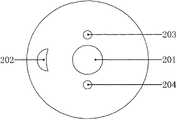
图3为外壳底部的仰视图;Fig. 3 is a bottom view of the bottom of the shell;
图4a为图1中A-A截面图,锤的极限位置1,芯的极限位置1;Fig. 4a is a sectional view of A-A in Fig. 1, the
图4b为图1中A-A截面图,锤的极限位置2,芯的极限位置2;Fig. 4b is a sectional view of A-A in Fig. 1, the
图5为锤的正向局部剖视图,外锤螺旋上升角为θ;Fig. 5 is a positive partial sectional view of the hammer, and the helical rising angle of the outer hammer is θ;
图6为外壳的正视图,内部空腔205螺旋上升角为θ(或者冲击面206螺旋上升角为θ);Fig. 6 is a front view of the shell, the helix angle of the
图中标记:1-盖;2-外壳;3-锤;4-芯;101-第一盖孔;102-第二盖孔;103-第三盖孔;201-第一壳通孔;202-第二壳通孔;203-第三壳通孔;204-第四壳通孔;205-外锤空腔;21-内锤第一空腔;22-内锤第二空腔,206-冲击面;301-内锤;302-外锤;303-第一外锤通孔;304-第二外锤通孔;305-第一内锤通孔;306-第二内锤通孔;401-第一芯孔;402-第二芯孔;403-第三芯孔;404-内锤第三空腔。Marks in the figure: 1-cover; 2-shell; 3-hammer; 4-core; 101-first cover hole; 102-second cover hole; 103-third cover hole; 201-first shell through hole; 202 - second shell through hole; 203 - third shell through hole; 204 - fourth shell through hole; 205 - outer hammer cavity; 21 - inner hammer first cavity; 22 - inner hammer second cavity, 206 - Impact surface; 301-inner hammer; 302-outer hammer; 303-first outer hammer through hole; 304-second outer hammer through hole; 305-first inner hammer through hole; 306-second inner hammer through hole; 401 - first core hole; 402 - second core hole; 403 - third core hole; 404 - third cavity of inner hammer.
具体实施方式Detailed ways
下面结合附图和具体实施方式对本发明做进一步的详细说明。The present invention will be further described in detail below in conjunction with the accompanying drawings and specific embodiments.
参照附图1,一种三向冲击工具主要由盖1、外壳2、锤3、芯4组成,芯4在内,锤3在外,二者封闭在盖1与外壳2内部;盖1上有第一盖孔101、第二盖孔102和第三盖孔103;外壳2呈凹形柱体,底部有-第一壳通孔201、外壳还设有第二壳通孔202、第三壳通孔203,外壳2上部与盖1联接;外壳内部有内锤第一空腔21;内锤第二空腔22和外锤空腔205,其中内锤第一空腔21和内锤第二空腔22分别与与第二盖孔102和第三盖孔103相通,内锤第一空腔21和内锤第二空腔22分别位于孔第二壳通孔202的两侧;外锤空腔205由盖1、外壳2和锤3封闭而成,外锤空腔205螺旋上升角θ;锤3呈中空柱形,有内锤301和与外锤空腔205螺旋上升角相配合的外锤302;内锤301两侧有第一内锤通孔305;第二内锤通孔306,并封闭在主要由盖1、锤3和芯4组成的内锤第三空腔404内,能转动;外锤302两侧有第一外锤通孔303;第二外锤通孔304;,并封闭在外锤空腔205内,能转动;所述芯4为中空柱形,内有相通的孔401、402与403,其中孔402为芯4的侧向开孔,孔403直径小于孔401,且位于孔401与侧孔402下方;外壳2可与钻头等部件联接。With reference to accompanying
钻井过程中,来自钻柱里的泥浆通过盖上的第一盖孔101;第二盖孔102和第三盖孔103,参照附图1、2、3、4,一部分直接由第三芯孔403流出工具,其余流体分别进入内锤第一空腔21、内锤第二空腔22和第一芯孔401;经内锤第一空腔21、内锤第二空腔22流体经第一内锤通孔305和第二内锤通孔306进入内锤第三空腔404中(图4a),再由第一内锤通孔305和第二内锤通孔306到-第二壳通孔202流出工具;经第一芯孔401的流体经第二芯孔402进入外锤两侧的第一外锤通孔303和第二外锤通孔304;,进入外锤空腔205推动锤3逆时针转动,至其极限位置冲击面206时,流体由第一外锤通孔303和第二外锤通孔304经外壳2底板第三壳通孔203和第四壳通孔204流出工具,芯4继续逆时针旋转至其极限位置(图4b),如此完成锤3的一个往复冲击循环,只要有流体流经本发明,锤3将以一定频率周而复始的螺旋向下冲击外壳2内的冲击面206。During the drilling process, the mud from the drill string passes through the
工作时,本发明的一种三向冲击工具下部与钻头联接,上部与钻铤联接。流经三向冲击工具的钻井液推动锤在外壳内封闭的相应区域内的极限位置之间螺旋往复冲击,钻头因此承受来自工具产生的螺旋向下的冲击方式和能量,钻头在旋转刮削岩石的同时,还在反复敲击岩石,提高较硬地层机械钻速和钻井效率。When working, the lower part of the three-way impact tool of the present invention is connected with the drill bit, and the upper part is connected with the drill collar. The drilling fluid flowing through the three-way impact tool pushes the hammer to reciprocate in a spiral between the limit positions in the corresponding closed area of the casing, so the drill bit bears the spiral downward impact mode and energy generated by the tool, and the drill bit rotates to scrape the rock. At the same time, rocks are being hammered repeatedly to increase the ROP and drilling efficiency in harder formations.
以上仅是实现本发明的一种方法,基于此发明原理的其它实现形式在本发明的范围之内。The above is only a method for realizing the present invention, and other realization forms based on the principles of the present invention are within the scope of the present invention.
Claims (8)
Priority Applications (1)
| Application Number | Priority Date | Filing Date | Title |
|---|---|---|---|
| CN201310097577.4ACN103147686B (en) | 2013-03-26 | 2013-03-26 | Three-way impact tool |
Applications Claiming Priority (1)
| Application Number | Priority Date | Filing Date | Title |
|---|---|---|---|
| CN201310097577.4ACN103147686B (en) | 2013-03-26 | 2013-03-26 | Three-way impact tool |
Publications (2)
| Publication Number | Publication Date |
|---|---|
| CN103147686Atrue CN103147686A (en) | 2013-06-12 |
| CN103147686B CN103147686B (en) | 2015-04-01 |
Family
ID=48545974
Family Applications (1)
| Application Number | Title | Priority Date | Filing Date |
|---|---|---|---|
| CN201310097577.4AActiveCN103147686B (en) | 2013-03-26 | 2013-03-26 | Three-way impact tool |
Country Status (1)
| Country | Link |
|---|---|
| CN (1) | CN103147686B (en) |
Citations (6)
| Publication number | Priority date | Publication date | Assignee | Title |
|---|---|---|---|---|
| EP0383737A1 (en)* | 1989-02-13 | 1990-08-22 | Sandvik Aktiebolag | Drill bit |
| US20020166700A1 (en)* | 2001-05-11 | 2002-11-14 | Gillis Peter J. | Rotational impact drill assembly |
| CN101463709A (en)* | 2009-01-08 | 2009-06-24 | 西南石油大学 | Torsional impact drilling tool |
| CN102434096A (en)* | 2010-09-29 | 2012-05-02 | 张家口汇洋机械有限公司 | Spiral percussion drill |
| CN102454364A (en)* | 2010-10-19 | 2012-05-16 | 中国石油化工集团公司 | Torsional impact drilling tool |
| CN203271585U (en)* | 2013-03-26 | 2013-11-06 | 徐正强 | Three-way impact tool |
- 2013
- 2013-03-26CNCN201310097577.4Apatent/CN103147686B/enactiveActive
Patent Citations (6)
| Publication number | Priority date | Publication date | Assignee | Title |
|---|---|---|---|---|
| EP0383737A1 (en)* | 1989-02-13 | 1990-08-22 | Sandvik Aktiebolag | Drill bit |
| US20020166700A1 (en)* | 2001-05-11 | 2002-11-14 | Gillis Peter J. | Rotational impact drill assembly |
| CN101463709A (en)* | 2009-01-08 | 2009-06-24 | 西南石油大学 | Torsional impact drilling tool |
| CN102434096A (en)* | 2010-09-29 | 2012-05-02 | 张家口汇洋机械有限公司 | Spiral percussion drill |
| CN102454364A (en)* | 2010-10-19 | 2012-05-16 | 中国石油化工集团公司 | Torsional impact drilling tool |
| CN203271585U (en)* | 2013-03-26 | 2013-11-06 | 徐正强 | Three-way impact tool |
Also Published As
| Publication number | Publication date |
|---|---|
| CN103147686B (en) | 2015-04-01 |
Similar Documents
| Publication | Publication Date | Title |
|---|---|---|
| CN108708672B (en) | A kind of circumferential direction axial vacuum impact speed-raising tool | |
| CN104847259B (en) | A kind of power drilling tool rotary impact speed enhancing apparatus | |
| CN102191915B (en) | Resonant pulse vibrating drilling device | |
| CN206071449U (en) | Drilling speed percussion mechanism | |
| CN103696696B (en) | The sliding PDC drill bit of anti-sticking | |
| CN105927147B (en) | A kind of percussion drilling speed-raising tool and method | |
| CN105239929A (en) | Downhole tool for achieving efficient rock breaking through spin vibration | |
| CN203701951U (en) | Torsion impact generator | |
| CN105221068A (en) | Percussion is utilized to improve the New Type of PDC Bit of heart portion efficiency of breaking rock | |
| CN101463709A (en) | Torsional impact drilling tool | |
| CN202990851U (en) | Screw type high-frequency percussion drilling tool | |
| CN103883247B (en) | A kind of high-frequency reciprocating torsion generator | |
| CN107664012A (en) | The two-way high frequency composite impact device of turbine type | |
| CN206129207U (en) | Novel oscillatory surge ware based on turbine and cam | |
| CN106223832A (en) | Compound Impact Drilling Tools | |
| CN108798521A (en) | A kind of reciprocating axial impact pressue device | |
| CN108547571B (en) | An eccentric torsional percussion drilling tool | |
| CN106639864A (en) | Vibrating impacting short piece | |
| CN103216196A (en) | Drilling head capable of drilling into rock used for engineering pile | |
| CN205172416U (en) | Mechanical oscillation strikes transmission shaft | |
| CN110159189A (en) | It surges composite impact device and its control method | |
| CN207436906U (en) | The two-way high frequency composite impact device of turbine type | |
| CN102392598B (en) | Hydraulic vibration impactor and pile driving power head comprising same | |
| CN106639859B (en) | A kind of mechanical oscillation impact transmission shaft | |
| CN103147686B (en) | Three-way impact tool |
Legal Events
| Date | Code | Title | Description |
|---|---|---|---|
| C06 | Publication | ||
| PB01 | Publication | ||
| C10 | Entry into substantive examination | ||
| SE01 | Entry into force of request for substantive examination | ||
| C14 | Grant of patent or utility model | ||
| GR01 | Patent grant | ||
| TR01 | Transfer of patent right | ||
| TR01 | Transfer of patent right | Effective date of registration:20250407 Address after:Room 50, Room 08, 6th Floor, Yashi Business Building, No. 12 Haifu Road, Haifu Street, Meilan District, Haikou City, Hainan Province 570203 Patentee after:Linlong Time and Space Investment (Haikou) Co.,Ltd. Country or region after:China Address before:100192 Beijing Haidian District Xiaoying East Road Expert International Garden 18-1-102 Patentee before:Xu Zhengqiang Country or region before:China |