CN103119647A - Complex Predictive Stereo Coding Based on Modified Discrete Cosine Transform - Google Patents
Complex Predictive Stereo Coding Based on Modified Discrete Cosine TransformDownload PDFInfo
- Publication number
- CN103119647A CN103119647ACN2011800253052ACN201180025305ACN103119647ACN 103119647 ACN103119647 ACN 103119647ACN 2011800253052 ACN2011800253052 ACN 2011800253052ACN 201180025305 ACN201180025305 ACN 201180025305ACN 103119647 ACN103119647 ACN 103119647A
- Authority
- CN
- China
- Prior art keywords
- signal
- level
- frequency domain
- domain representation
- time
- Prior art date
- Legal status (The legal status is an assumption and is not a legal conclusion. Google has not performed a legal analysis and makes no representation as to the accuracy of the status listed.)
- Granted
Links
Images


Classifications
- G—PHYSICS
- G10—MUSICAL INSTRUMENTS; ACOUSTICS
- G10L—SPEECH ANALYSIS TECHNIQUES OR SPEECH SYNTHESIS; SPEECH RECOGNITION; SPEECH OR VOICE PROCESSING TECHNIQUES; SPEECH OR AUDIO CODING OR DECODING
- G10L19/00—Speech or audio signals analysis-synthesis techniques for redundancy reduction, e.g. in vocoders; Coding or decoding of speech or audio signals, using source filter models or psychoacoustic analysis
- G10L19/008—Multichannel audio signal coding or decoding using interchannel correlation to reduce redundancy, e.g. joint-stereo, intensity-coding or matrixing
- G—PHYSICS
- G01—MEASURING; TESTING
- G01L—MEASURING FORCE, STRESS, TORQUE, WORK, MECHANICAL POWER, MECHANICAL EFFICIENCY, OR FLUID PRESSURE
- G01L19/00—Details of, or accessories for, apparatus for measuring steady or quasi-steady pressure of a fluent medium insofar as such details or accessories are not special to particular types of pressure gauges
- G—PHYSICS
- G06—COMPUTING OR CALCULATING; COUNTING
- G06F—ELECTRIC DIGITAL DATA PROCESSING
- G06F3/00—Input arrangements for transferring data to be processed into a form capable of being handled by the computer; Output arrangements for transferring data from processing unit to output unit, e.g. interface arrangements
- G06F3/16—Sound input; Sound output
- G06F3/162—Interface to dedicated audio devices, e.g. audio drivers, interface to CODECs
- G—PHYSICS
- G10—MUSICAL INSTRUMENTS; ACOUSTICS
- G10L—SPEECH ANALYSIS TECHNIQUES OR SPEECH SYNTHESIS; SPEECH RECOGNITION; SPEECH OR VOICE PROCESSING TECHNIQUES; SPEECH OR AUDIO CODING OR DECODING
- G10L19/00—Speech or audio signals analysis-synthesis techniques for redundancy reduction, e.g. in vocoders; Coding or decoding of speech or audio signals, using source filter models or psychoacoustic analysis
- G10L19/002—Dynamic bit allocation
- G—PHYSICS
- G10—MUSICAL INSTRUMENTS; ACOUSTICS
- G10L—SPEECH ANALYSIS TECHNIQUES OR SPEECH SYNTHESIS; SPEECH RECOGNITION; SPEECH OR VOICE PROCESSING TECHNIQUES; SPEECH OR AUDIO CODING OR DECODING
- G10L19/00—Speech or audio signals analysis-synthesis techniques for redundancy reduction, e.g. in vocoders; Coding or decoding of speech or audio signals, using source filter models or psychoacoustic analysis
- G10L19/012—Comfort noise or silence coding
- G—PHYSICS
- G10—MUSICAL INSTRUMENTS; ACOUSTICS
- G10L—SPEECH ANALYSIS TECHNIQUES OR SPEECH SYNTHESIS; SPEECH RECOGNITION; SPEECH OR VOICE PROCESSING TECHNIQUES; SPEECH OR AUDIO CODING OR DECODING
- G10L19/00—Speech or audio signals analysis-synthesis techniques for redundancy reduction, e.g. in vocoders; Coding or decoding of speech or audio signals, using source filter models or psychoacoustic analysis
- G10L19/02—Speech or audio signals analysis-synthesis techniques for redundancy reduction, e.g. in vocoders; Coding or decoding of speech or audio signals, using source filter models or psychoacoustic analysis using spectral analysis, e.g. transform vocoders or subband vocoders
- G10L19/022—Blocking, i.e. grouping of samples in time; Choice of analysis windows; Overlap factoring
- G—PHYSICS
- G10—MUSICAL INSTRUMENTS; ACOUSTICS
- G10L—SPEECH ANALYSIS TECHNIQUES OR SPEECH SYNTHESIS; SPEECH RECOGNITION; SPEECH OR VOICE PROCESSING TECHNIQUES; SPEECH OR AUDIO CODING OR DECODING
- G10L19/00—Speech or audio signals analysis-synthesis techniques for redundancy reduction, e.g. in vocoders; Coding or decoding of speech or audio signals, using source filter models or psychoacoustic analysis
- G10L19/02—Speech or audio signals analysis-synthesis techniques for redundancy reduction, e.g. in vocoders; Coding or decoding of speech or audio signals, using source filter models or psychoacoustic analysis using spectral analysis, e.g. transform vocoders or subband vocoders
- G10L19/03—Spectral prediction for preventing pre-echo; Temporary noise shaping [TNS], e.g. in MPEG2 or MPEG4
- G—PHYSICS
- G10—MUSICAL INSTRUMENTS; ACOUSTICS
- G10L—SPEECH ANALYSIS TECHNIQUES OR SPEECH SYNTHESIS; SPEECH RECOGNITION; SPEECH OR VOICE PROCESSING TECHNIQUES; SPEECH OR AUDIO CODING OR DECODING
- G10L19/00—Speech or audio signals analysis-synthesis techniques for redundancy reduction, e.g. in vocoders; Coding or decoding of speech or audio signals, using source filter models or psychoacoustic analysis
- G10L19/04—Speech or audio signals analysis-synthesis techniques for redundancy reduction, e.g. in vocoders; Coding or decoding of speech or audio signals, using source filter models or psychoacoustic analysis using predictive techniques
- G10L19/06—Determination or coding of the spectral characteristics, e.g. of the short-term prediction coefficients
- G—PHYSICS
- G10—MUSICAL INSTRUMENTS; ACOUSTICS
- G10L—SPEECH ANALYSIS TECHNIQUES OR SPEECH SYNTHESIS; SPEECH RECOGNITION; SPEECH OR VOICE PROCESSING TECHNIQUES; SPEECH OR AUDIO CODING OR DECODING
- G10L19/00—Speech or audio signals analysis-synthesis techniques for redundancy reduction, e.g. in vocoders; Coding or decoding of speech or audio signals, using source filter models or psychoacoustic analysis
- G10L19/04—Speech or audio signals analysis-synthesis techniques for redundancy reduction, e.g. in vocoders; Coding or decoding of speech or audio signals, using source filter models or psychoacoustic analysis using predictive techniques
- G10L19/16—Vocoder architecture
- G10L19/167—Audio streaming, i.e. formatting and decoding of an encoded audio signal representation into a data stream for transmission or storage purposes
- G—PHYSICS
- G10—MUSICAL INSTRUMENTS; ACOUSTICS
- G10L—SPEECH ANALYSIS TECHNIQUES OR SPEECH SYNTHESIS; SPEECH RECOGNITION; SPEECH OR VOICE PROCESSING TECHNIQUES; SPEECH OR AUDIO CODING OR DECODING
- G10L19/00—Speech or audio signals analysis-synthesis techniques for redundancy reduction, e.g. in vocoders; Coding or decoding of speech or audio signals, using source filter models or psychoacoustic analysis
- G10L19/04—Speech or audio signals analysis-synthesis techniques for redundancy reduction, e.g. in vocoders; Coding or decoding of speech or audio signals, using source filter models or psychoacoustic analysis using predictive techniques
- G10L19/16—Vocoder architecture
- G10L19/18—Vocoders using multiple modes
- H—ELECTRICITY
- H04—ELECTRIC COMMUNICATION TECHNIQUE
- H04S—STEREOPHONIC SYSTEMS
- H04S3/00—Systems employing more than two channels, e.g. quadraphonic
- H04S3/008—Systems employing more than two channels, e.g. quadraphonic in which the audio signals are in digital form, i.e. employing more than two discrete digital channels
- G—PHYSICS
- G10—MUSICAL INSTRUMENTS; ACOUSTICS
- G10L—SPEECH ANALYSIS TECHNIQUES OR SPEECH SYNTHESIS; SPEECH RECOGNITION; SPEECH OR VOICE PROCESSING TECHNIQUES; SPEECH OR AUDIO CODING OR DECODING
- G10L19/00—Speech or audio signals analysis-synthesis techniques for redundancy reduction, e.g. in vocoders; Coding or decoding of speech or audio signals, using source filter models or psychoacoustic analysis
- G10L19/02—Speech or audio signals analysis-synthesis techniques for redundancy reduction, e.g. in vocoders; Coding or decoding of speech or audio signals, using source filter models or psychoacoustic analysis using spectral analysis, e.g. transform vocoders or subband vocoders
- G10L19/0212—Speech or audio signals analysis-synthesis techniques for redundancy reduction, e.g. in vocoders; Coding or decoding of speech or audio signals, using source filter models or psychoacoustic analysis using spectral analysis, e.g. transform vocoders or subband vocoders using orthogonal transformation
- G—PHYSICS
- G10—MUSICAL INSTRUMENTS; ACOUSTICS
- G10L—SPEECH ANALYSIS TECHNIQUES OR SPEECH SYNTHESIS; SPEECH RECOGNITION; SPEECH OR VOICE PROCESSING TECHNIQUES; SPEECH OR AUDIO CODING OR DECODING
- G10L25/00—Speech or voice analysis techniques not restricted to a single one of groups G10L15/00 - G10L21/00
- G10L25/03—Speech or voice analysis techniques not restricted to a single one of groups G10L15/00 - G10L21/00 characterised by the type of extracted parameters
- G10L25/12—Speech or voice analysis techniques not restricted to a single one of groups G10L15/00 - G10L21/00 characterised by the type of extracted parameters the extracted parameters being prediction coefficients
- H—ELECTRICITY
- H04—ELECTRIC COMMUNICATION TECHNIQUE
- H04S—STEREOPHONIC SYSTEMS
- H04S2400/00—Details of stereophonic systems covered by H04S but not provided for in its groups
- H04S2400/01—Multi-channel, i.e. more than two input channels, sound reproduction with two speakers wherein the multi-channel information is substantially preserved
Landscapes
- Engineering & Computer Science (AREA)
- Physics & Mathematics (AREA)
- Multimedia (AREA)
- Acoustics & Sound (AREA)
- Signal Processing (AREA)
- Human Computer Interaction (AREA)
- Health & Medical Sciences (AREA)
- Audiology, Speech & Language Pathology (AREA)
- Computational Linguistics (AREA)
- Spectroscopy & Molecular Physics (AREA)
- Mathematical Physics (AREA)
- General Physics & Mathematics (AREA)
- Theoretical Computer Science (AREA)
- General Engineering & Computer Science (AREA)
- General Health & Medical Sciences (AREA)
- Compression, Expansion, Code Conversion, And Decoders (AREA)
- Stereophonic System (AREA)
- Compression Or Coding Systems Of Tv Signals (AREA)
- Stereo-Broadcasting Methods (AREA)
Abstract
Description
Translated fromChinese技术领域technical field
这里公开的本发明总的来说涉及立体声音频编码,更确切地,涉及在频域中使用复数预测进行立体声编码的技术。The invention disclosed herein relates generally to stereo audio coding, and more specifically to techniques for stereo coding using complex prediction in the frequency domain.
背景技术Background technique
立体声信号左(L)和右(R)声道的联合编码与L和R的独立编码相比能够更有效地编码。用于联合立体声编码的普通方法是中/侧(mid/side,M/S)编码。这里,中间(M)信号通过将L和R信号相加而形成,例如,该M信号可具有如下形式:Joint coding of the left (L) and right (R) channels of a stereo signal enables more efficient coding than independent coding of L and R. A common method for joint stereo coding is mid/side (M/S) coding. Here, the intermediate (M) signal is formed by adding the L and R signals, for example, this M signal can have the following form:
M=(L+R)/2M=(L+R)/2
此外,侧边(side,S)信号通过将两声道L和R信号相减而形成,例如,该S信号可具有如下形式:Furthermore, a side (S) signal is formed by subtracting the two-channel L and R signals, for example, the S signal may have the following form:
S=(L-R)/2S=(L-R)/2
在M/S编码情况下,M和S信号而不是L和R信号被编码。In the case of M/S encoding, M and S signals are encoded instead of L and R signals.
在运动图像专家组(Moving Picture Experts Group,MPEG)高级音频编码(Advanced Audio Coding,AAC)标准中(见标准文件ISO/IEC13818-7),能够以时变和频变方式选择L/R立体声编码和M/S立体声编码。因此,立体声编码器能够对立体声信号的某些频带应用L/R编码,而M/S编码用于编码该立体声信号的其他频带(频变)。此外,该编码器能够随时间在L/R和M/S编码之间切换(时变)。在MPEG AAC中,立体声编码在频域中进行,更具体而言,在改进型离散余弦变换(modified discretecosine transform,MDCT)域中进行。这允许以频率和时间可变的方式自适应地选择L/R或M/S编码。In the Moving Picture Experts Group (MPEG) Advanced Audio Coding (AAC) standard (see standard document ISO/IEC13818-7), L/R stereo coding can be selected in a time-varying and frequency-varying manner and M/S stereo encoding. Thus, a stereo encoder is able to apply L/R coding to some frequency bands of a stereo signal, while M/S coding is used to code other frequency bands of the stereo signal (frequency shifting). Furthermore, this encoder is able to switch between L/R and M/S encoding over time (time-varying). In MPEG AAC, stereo coding is performed in the frequency domain, more specifically, in the modified discrete cosine transform (MDCT) domain. This allows adaptive selection of L/R or M/S coding in a frequency and time variable manner.
参数立体声编码是用于有效地将立体声音频信号编码为单耳听觉信号加少量用于立体声参数的边信息的技术。其是MPEG-4音频标准(见标准文件ISO/IEC 14496-3)的一部分。能够使用任何音频编码器对单耳听觉信号编码。立体声参数可被嵌入单声道比特流的辅助部分,从而实现完全的向前和向后兼容。在解码器中,首先解码的是单耳听觉信号,在这之后,借助于立体声参数重建立体声信号。通过去相关器(例如,可包括一条或更多条延迟线的适当的全通滤波器)来产生已解码单声道信号的去相关版本,其与单声道信号零互相关。本质上,已去相关信号具有与单声道信号相同的频谱和时间能量分布。单耳听觉信号连同已去相关信号被输入到通过立体声参数来控制并重建立体声信号的上混(up-mix)处理。更多信息参见H.Purnhagen所著的论文:“Low complexity Parametric StereoCoding in MPEG-4(MPEG-4中的低复杂度参数立体声编码)”(第七届数字音频影响国际会议(DAFx’04)会刊,意大利那不勒斯,2004年10月5-8日,第163至168页)。Parametric stereo coding is a technique for efficiently encoding a stereo audio signal into a monaural auditory signal plus a small amount of side information for the stereo parameters. It is part of the MPEG-4 audio standard (see standard document ISO/IEC 14496-3). The monaural auditory signal can be encoded using any audio encoder. Stereo parameters can be embedded in the auxiliary part of the mono bitstream, allowing full forward and backward compatibility. In the decoder, the monaural auditory signal is first decoded, after which the stereo signal is reconstructed with the aid of the stereo parameters. A decorrelated version of the decoded mono signal is produced by a decorrelator (eg a suitable all-pass filter which may include one or more delay lines), which is zero cross-correlated with the mono signal. Essentially, a decorrelated signal has the same spectral and temporal energy distribution as a mono signal. The monaural auditory signal along with the decorrelated signal is input to an up-mix process which is controlled by the stereo parameters and reconstructs the stereo signal. For more information, see the paper written by H.Purnhagen: "Low complexity Parametric StereoCoding in MPEG-4 (Low complexity parametric stereo coding in MPEG-4)" (The Seventh International Conference on Digital Audio Impact (DAFx'04) Naples, Italy, 5-8 October 2004, pp. 163-168).
MPEG环绕(MPS;见ISO/IEC 23003-1和J.Herre等人所著的论文"MPEG Surround-The ISO/MPEG Standard for Efficient and CompatibleMulti-Channel Audio Coding(MPEG环绕——用于有效且兼容的多声道音频编码的ISO/MPEG标准)"(音频工程大会论文7084,第122届大会,2007年5月5-8日))允许将参数立体声编码原理与残留编码结合、用发送的残留信号代替去相关信号,从而提高感知质量。通过下混(down-mix)多声道信号,并且可选地,通过提取空间线索,可实现残留编码。在下混处理期间,代表误差信号的残留信号被计算,并且然后被编码和发送。在解码器中,它们可代替去相关信号。在混合的方法中,在某些频带中(优选在相对低的频带中),它们可代替去相关信号。MPEG Surround (MPS; see ISO/IEC 23003-1 and the paper "MPEG Surround-The ISO/MPEG Standard for Efficient and Compatible Multi-Channel Audio Coding" by J.Herre et al. ISO/MPEG Standard for Multichannel Audio Coding)" (Audio Engineering Conference Paper 7084, 122nd Session, May 5-8, 2007)) allows combining parametric stereo coding principles with residual coding, using the transmitted residual signal instead of decorrelated signals, thus improving perceptual quality. Residual coding can be achieved by down-mixing the multi-channel signal, and optionally by extracting spatial cues. During the downmix process, a residual signal representing the error signal is calculated and then encoded and transmitted. In the decoder, they can replace the decorrelated signals. In a hybrid approach, they may replace decorrelated signals in certain frequency bands, preferably in relatively low frequency bands.
根据当前的MPEG统一语音和音频编码(Unified Speech and AudioCoding,USAC)系统(其两个示例在图1中示出),解码器包括位于核心解码器下游的复数值的正交镜像滤波器(quadrature mirror filter,QMF)组。作为滤波器组输出而获得的QMF表示是复数(因此通过因子2过采样),并可被布置作为下混信号(或相当于中间信号)M和残留信号D,带有复数条目的上混矩阵被施加到所述下混信号的残留信号。L和R信号(在QMF域中)如下获得:According to the current MPEG Unified Speech and Audio Coding (USAC) system (two examples of which are shown in Figure 1), the decoder includes a complex-valued quadrature mirror filter (quadrature mirror filter, QMF) group. The QMF representation obtained as filter bank output is complex (hence oversampled by a factor of 2) and can be arranged as a downmix signal (or equivalently an intermediate signal) M and a residual signal D, an upmix matrix with complex entries A residual signal that is applied to the downmix signal. The L and R signals (in the QMF domain) are obtained as follows:
其中,g是实数值的增益因子,且α是复数值的预测系数。优选地,α被选择为使得残留信号D的能量被最小化。该增益因子可通过归一化来确定,即,保证和信号的功率等于左和右信号的功率和。L和R信号中的每一个的实部与虚部是互冗余的(原理上,它们中的每一个可基于另一个来计算),但是有利于在不发生可听见的混叠假影(aliasing artifact)的情况下实现随后的谱带复制(spectral band replication,SBR)解码器的应用。也可出于相似的原因选择使用过采样的信号表示,以防止与其他诸如单声道-带-立体声的上混等时间或频率自适应信号处理(未示出)相关联的假影。逆QMF滤波是解码器中的最后处理步骤。需要注意的是,信号的带限QMF表示允许使用带限残留技术和"残留填充"技术,这些技术可集成到该类解码器中。where g is a real-valued gain factor and α is a complex-valued prediction coefficient. Preferably, α is chosen such that the energy of the residual signal D is minimized. This gain factor can be determined by normalization, ie, to ensure that the power of the sum signal is equal to the sum of the power of the left and right signals. The real and imaginary parts of each of the L and R signals are mutually redundant (in principle, each of them can be computed based on the other), but it is advantageous to avoid audible aliasing artifacts ( The application of the subsequent spectral band replication (SBR) decoder is realized in the case of aliasing artifact). Using an oversampled signal representation may also be chosen for similar reasons to prevent artifacts associated with other time or frequency adaptive signal processing (not shown) such as mono-band-stereo upmixing. Inverse QMF filtering is the final processing step in the decoder. Note that the band-limited QMF representation of the signal allows the use of band-limited residual techniques and "residual filling" techniques, which can be integrated into this class of decoders.
上述编码结构很适于低比特率(通常低于80kb/s),但是考虑到计算复杂性,对于更高比特率,上述编码结构不是最优的。更确切地说,在更高比特率,通常不使用SBR工具(因为它不会提高编码效率)。那么,在没有SBR级的解码器中,仅有复数值的上混矩阵促动QMF滤波器组的存在,这在计算上是费力的,并且引入了延迟(在1024个采样的帧长下,QMF分析/合成滤波器组引入了961个采样的延迟)。这清楚地表明需要更有效的编码结构。The above encoding structure is well suited for low bit rates (typically below 80kb/s), but is not optimal for higher bit rates considering computational complexity. More precisely, at higher bitrates, the SBR tool is generally not used (as it does not improve encoding efficiency). Then, in a decoder without an SBR stage, only the complex-valued upmix matrix drives the presence of a QMF filter bank, which is computationally expensive and introduces a delay (at a frame length of 1024 samples, The QMF analysis/synthesis filterbank introduces a delay of 961 samples). This clearly indicates the need for more efficient encoding structures.
发明内容Contents of the invention
本发明的一个目的是提供在高比特率范围中也在计算上有效的立体声编码的方法和装置。It is an object of the present invention to provide a method and arrangement for stereo coding which is also computationally efficient in the high bit rate range.
如独立权利要求所限定的,本发明通过提供分别用于编码和解码的编码器和解码器、编码和解码方法以及计算机程序产品来达到此目的。从属权利要求限定本发明的实施例。The invention achieves this object by providing an encoder and a decoder, an encoding and decoding method and a computer program product for encoding and decoding respectively, as defined in the independent claims. The dependent claims define embodiments of the invention.
在第一方面中,本发明提供一种解码器系统,该解码器系统用于通过复数预测立体声编码来提供立体声信号,其包括:In a first aspect, the invention provides a decoder system for providing a stereo signal by complex predictive stereo coding, comprising:
上混,该上混适于:基于下混信号(M)和残留信号(D)的第一频域表示产生立体声信号,其中每一个第一频域表示包括第一频谱分量,该第一频谱分量代表相应信号的在多维空间的第一子空间中表示的频谱内容,该上混级包括:upmixing adapted to: generate a stereo signal based on first frequency-domain representations of the downmix signal (M) and the residual signal (D), wherein each first frequency-domain representation comprises a first spectral component, the first spectral The components represent the spectral content of the corresponding signal represented in the first subspace of the multidimensional space, the upmixing stages comprising:
基于下混信号的第一频域表示来计算该下混信号的第二频域表示的模块,其中,该第二频域表示包括第二频谱分量,该第二频谱分量代表信号的在多维空间的第二子空间中表示的频谱内容,其中该多维空间的第二子空间包括多维空间的不含在第一子空间内的部分。means for calculating a second frequency domain representation of the downmix signal based on the first frequency domain representation of the downmix signal, wherein the second frequency domain representation includes a second spectral component representing a multidimensional space of the signal The spectral content represented in the second subspace of the multidimensional space, wherein the second subspace of the multidimensional space includes the part of the multidimensional space not contained in the first subspace.
加权求和器,该加权求和器基于该下混信号的第一和第二频域表示、残留信号的第一频域表示和编码在比特流信号中的复数预测系数(α)来计算侧边信号(S);和a weighted summer that calculates side side signal(s); and
求和与求差级,该求和与求差级基于下混信号的第一频域表示和侧边信号计算立体声信号,a summation and difference stage that computes the stereo signal based on the first frequency domain representation of the downmix signal and the side signals,
其中,上混级还可以工作于通过模式(pass-through mode),其中所述下混和残留信号被直接提供给求和与求差级。Wherein, the upmixing stage can also work in a pass-through mode, wherein the downmixing and residual signal is directly provided to the summing and difference stage.
在第二方面中,本发明提供一种编码器系统,用于通过复数预测立体声编码、通过比特流信号对立体声信号编码,该编码器系统包括:In a second aspect, the invention provides an encoder system for encoding a stereo signal by a bitstream signal by complex predictive stereo coding, the encoder system comprising:
估计器,用于估计复数预测系数;an estimator for estimating complex prediction coefficients;
编码级,可操作用于:(a)以通过该复数预测系数值而确定的关系,将立体声信号变换成下混和残留信号的频域表示;以及an encoding stage operable to: (a) transform the stereo signal into a frequency-domain representation of the downmixed residual signal in a relationship determined by the complex prediction coefficient values; and
复用器,用于从编码级和估计器接收输出,并通过所述比特流信号对其进行编码。a multiplexer for receiving outputs from the encoding stage and the estimator and encoding them with said bitstream signal.
在本发明的第三和第四方面中,提供用于将立体声信号编码成比特流和将比特流解码成至少一个立体声信号的方法。每个方法的技术特征分别与所述编码器系统和解码器系统相似。在第五和第六方面中,本发明还提供一种包含用于在计算机上执行每个方法的指令的计算机程序产品。In a third and fourth aspect of the invention, methods are provided for encoding a stereo signal into a bitstream and decoding the bitstream into at least one stereo signal. The technical features of each method are similar to the encoder system and decoder system respectively. In the fifth and sixth aspects, the invention also provides a computer program product comprising instructions for performing each method on a computer.
本发明受益于MPEG USAC系统中的统一立体声编码的优点。在较高比特率(在这样的比特率下通常SBR不被采用)下也可保持这些优点,而不明显地增加伴随着基于QMF方法的计算复杂性。这可能是因为:至少在下混和残留声道的代码音频带宽相同且上混处理不包括去相关的情况下,作为MPEG USAC变换编码系统基础的临界采样的MDCT变换可被用于本发明所提供的复数预测立体声编码。这意味着不再需要附加的QMF变换。与传统的L/R或M/S立体声相比,QMF域中的复数预测立体声编码的代表性实现实际上显著增加了每单位时间的操作数量。因此,根据本发明的编码装置在这样的比特率下显得有竞争力,以适中的计算代价提供高音频质量。The present invention benefits from the advantages of unified stereo coding in the MPEG USAC system. These advantages can also be maintained at higher bit rates (at which SBR is generally not employed) without significantly increasing the computational complexity that accompanies QMF-based methods. This may be due to the fact that the critically sampled MDCT transform that is the basis of the MPEG USAC transform coding system can be used to provide the advantage provided by the present invention, at least if the coded audio bandwidths of the downmix and residual channels are the same and the upmix process does not include decorrelation. Complex predictive stereo coding. This means that an additional QMF transformation is no longer required. Representative implementations of complex predictive stereo coding in the QMF domain actually significantly increase the number of operations per unit of time compared to conventional L/R or M/S stereo. Therefore, the encoding device according to the invention appears competitive at such bit rates, providing high audio quality at a moderate computational cost.
如本领域技术人员了解的,该上混级还可以操作于通过模式的事实使解码器能够按照如编码器侧所确定的传统的直接或联合编码以及复数预测编码来自适应解码。因此,在解码器不能肯定地将质量水平提高到超过常规的直接L/R立体声编码或联合M/S立体声编码的质量水平的情况下,解码器至少能够保证保持相同水平。因此,从功能的角度看,根据本发明的此方面的解码器可被认为是相对于背景技术的超集。As understood by those skilled in the art, the fact that this upmixing stage can also operate in pass-through mode enables the decoder to adapt decoding according to conventional direct or joint coding as well as complex predictive coding as determined at the encoder side. Thus, in cases where the decoder cannot definitely increase the quality level beyond that of conventional direct L/R stereo coding or joint M/S stereo coding, the decoder is at least guaranteed to maintain the same level. Therefore, from a functional point of view, the decoder according to this aspect of the invention can be considered as a superset with respect to the background art.
作为与基于QMF的预测编码立体声相对比的优点,信号的完美重建是可能的(除了量化误差之外,能够使量化误差任意小)。As an advantage over QMF-based predictively coded stereo, perfect reconstruction of the signal is possible (in addition to the quantization error, which can be made arbitrarily small).
因此,本发明提供用于通过复数预测进行基于变换的立体声编码的编码装置。优选地,根据本发明的装置不限于复数预测立体声编码,而还可操作于根据背景技术的L/R立体声编码或联合M/S立体声编码方式,使得可为特定应用或在特定时间间隔期间选择最合适的编码方法。Accordingly, the present invention provides an encoding device for transform-based stereo encoding by complex prediction. Preferably, the device according to the invention is not limited to complex predictive stereo coding, but is also operable in L/R stereo coding or joint M/S stereo coding according to the background art, so that it can be selected for a specific application or during a specific time interval The most appropriate encoding method.
信号的过采样(例如,复数)表示(包括所述第一和所述第二频谱分量)作为基础被用于本发明的复数预测,并因此,用于计算这种过采样表示的模块被布置在根据本发明的编码器系统和解码器系统中。所述频谱分量涉及多维空间的第一和第二子空间,其可为关于给定长度的时间间隔(例如,预设的时间帧长)的以有限采样频率采样的时间依赖函数集。众所周知,在该特定多维空间中的函数可由基函数的有限加权和来近似。An oversampled (e.g. complex) representation of the signal (comprising said first and said second spectral components) is used as a basis for the complex prediction of the invention, and thus, the means for computing this oversampled representation are arranged In an encoder system and a decoder system according to the invention. The spectral components relate to the first and second subspaces of the multidimensional space, which may be time-dependent function sets sampled at a finite sampling frequency with respect to a time interval of a given length (eg, a preset time frame length). It is well known that functions in this particular multidimensional space can be approximated by a finite weighted sum of basis functions.
如本领域技术人员将理解的,为了能可靠地重新生成已编码信号,编码器适于与配有用于提供预测编码所基于的过采样表示的对等模块的解码器配合。这种对等模块可为相同或相似模块,或具有相同或相似的转移特性的模块。特别地,编码器和解码器中的模块分别可为执行各自计算机程序的相似或不相似的处理单元,其中计算机程序执行对等的数学运算集。As will be appreciated by those skilled in the art, in order to be able to reliably regenerate the encoded signal, the encoder is adapted to cooperate with a decoder equipped with a peer-to-peer module for providing an oversampled representation on which the predictive encoding is based. Such peer modules may be the same or similar modules, or modules with the same or similar transfer characteristics. In particular, the modules in the encoder and decoder, respectively, may be similar or dissimilar processing units executing respective computer programs, wherein the computer programs perform equivalent sets of mathematical operations.
在解码器系统或编码器系统的一些实施例中,第一频谱分量具有在第一子空间中表示的实数值,且第二频谱分量具有在第二子空间中表示的虚值。第一和第二频谱分量一起形成信号的复数频谱表示。第一子空间可为第一基函数集的线性生成空间(linear span),而第二子空间可为第二基函数集的线性生成空间,第二基函数中的一些与第一基函数集线性无关。In some embodiments of the decoder system or encoder system, the first spectral component has real values represented in the first subspace and the second spectral component has imaginary values represented in the second subspace. The first and second spectral components together form a complex spectral representation of the signal. The first subspace may be a linear span of the first set of basis functions, and the second subspace may be a linear span of the second set of basis functions, some of which are identical to the first set of basis functions linearly independent.
在一个实施例中,用于计算复数表示的模块为实到虚的变换,即,基于离散时间信号的实数频谱表示计算该信号的频谱虚部的模块。该变换可基于诸如来自谐波分析的公式或启发式(heuristic)关系等的精确或近似的数学关系。In one embodiment, the means for computing the complex representation is a real-to-imaginary transform, ie a means for computing the spectral imaginary part of a discrete-time signal based on its real spectral representation. The transformation may be based on exact or approximate mathematical relationships such as formulas from harmonic analysis or heuristic relationships.
在解码器系统或编码器系统的一些实施例中,可通过对离散时间域信号进行时-频域变换获得第一频谱分量,时-频域变换优选地为傅里叶变换,诸如离散余弦变换(discrete cosine transform,DCT)、改进型离散余弦变换(modified discrete cosine transform,MDCT)、离散正弦变换(discretesine transform,DST)、改进型离散正弦变换(modified discrete sinetransform,MDST)、快速傅里叶变换(fast Fourier transform,FFT)、或基于质数因子的傅里叶算法等。在前四个例子中,然后可分别通过DST、MDST、DCT和MDCT获得第二频谱分量。众所周知,以单位间隔为周期的余弦的线性生成空间形成不完全包含在以相同间隔为周期的正弦的线性生成空间中的子空间。优选地,第一频谱分量可通过MDCT获得,且第二频谱分量可通过MDST获得。In some embodiments of the decoder system or the encoder system, the first spectral component may be obtained by performing a time-frequency domain transform on the discrete time domain signal, the time-frequency domain transform is preferably a Fourier transform, such as a discrete cosine transform (discrete cosine transform, DCT), modified discrete cosine transform (modified discrete cosine transform, MDCT), discrete sine transform (discretesine transform, DST), modified discrete sine transform (modified discrete sine transform, MDST), fast Fourier transform (fast Fourier transform, FFT), or Fourier algorithm based on prime factor, etc. In the first four examples, the second spectral components can then be obtained by DST, MDST, DCT and MDCT, respectively. It is well known that the linearly generated space of cosines periodic at a unit interval forms a subspace that is not completely contained in the linearly generated space of sines periodic at the same interval. Preferably, the first spectral component is obtainable by MDCT and the second spectral component is obtainable by MDST.
在一个实施例中,解码器系统包括布置在上混级的上游的至少一个时域噪音成形模块(TNS(Temporal Noise Shaping)模块或TNS滤波器)。一般说来,TNS的使用提高了对具有类瞬态(transient-like)分量信号的感知音质,这也适用于本发明的以TNS为特征的解码器系统的实施例。在传统L/R和M/S立体声编码中,TNS滤波器可直接在逆变换之前作为频域中最后处理步骤被施加。然而,在复数预测立体声编码情况下,将TNS滤波器施加在下混和残留信号上(即在上混矩阵前)常常是有利的。换句话说,TNS被施加到左右声道的线性组合,这具有几个优点。首先,可被证实,在给定情况下TNS仅对比如下混信号有利。然后,对于残留信号可抑制或省去TNS滤波,这可能意味着可用带宽的更经济的使用,TNS滤波器系数仅需为下混信号传输。其次,复数预测编码中所需的下混信号的过采样表示的计算(例如,MDST数据被从MDCT数据中导出,以便形成复数频域表示)可要求在时域中下混信号的表示是可计算的。这又意味着下混信号优选地作为以一致方式获得的MDCT频谱的时间序列而得到。如果在将下混/残留表示转换成左/右表示的上混矩阵后在解码器中施加TNS滤波,则仅下混信号的TNS残留MDCT谱的序列是可得到的。这会使对应的MDST谱的有效计算非常困难,特别是在左右声道使用具有不同特性的TNS滤波器的情况下尤为如此。In one embodiment, the decoder system comprises at least one temporal noise shaping module (TNS (Temporal Noise Shaping) module or TNS filter) arranged upstream of the upmixing stage. In general, the use of TNS improves the perceived sound quality for signals with transient-like components, which also applies to embodiments of the decoder system of the present invention featuring TNS. In conventional L/R and M/S stereo coding, the TNS filter can be applied as a final processing step in the frequency domain directly before the inverse transform. However, in the case of complex predictive stereo coding it is often advantageous to apply the TNS filter on the downmix and residual signal (ie before the upmix matrix). In other words, TNS is applied to a linear combination of left and right channels, which has several advantages. First, it can be shown that TNS is only beneficial for downmixing signals in a given situation. TNS filtering can then be suppressed or omitted for the residual signal, which may imply a more economical use of the available bandwidth, the TNS filter coefficients need only be transmitted for the downmix signal. Second, the computation of an oversampled representation of the downmix signal required in complex predictive coding (e.g. MDST data is derived from MDCT data in order to form a complex frequency domain representation) may require that the representation of the downmix signal in the time domain be computational. This in turn means that the downmix signal is preferably obtained as a time series of MDCT spectra obtained in a consistent manner. If TNS filtering is applied in the decoder after converting the downmix/residual representation to the upmix matrix of the left/right representation, only the sequence of TNS residual MDCT spectra of the downmix signal is available. This can make efficient computation of the corresponding MDST spectrum very difficult, especially if the left and right channels use TNS filters with different characteristics.
需要强调的是,MDCT谱的时序的可得到性不是获得适合作为复数预测编码基础的MDST表示的绝对标准。除实验证据外,该事实可通过下面的方式解释:一般TNS只施加到诸如几千赫兹以上的较高频率,使得对于较低频率,由TNS滤波的残留信号近似地对应于未滤波的残留信号。因此,本发明可具体化为用于复数预测立体声编码的解码器,其中,如下面指出的,TNS滤波器具有不同于上混级的上游的位置。It should be emphasized that the availability of the timing of the MDCT spectrum is not an absolute criterion for obtaining an MDST representation suitable as a basis for complex predictive coding. Apart from experimental evidence, this fact can be explained in the following way: in general TNS is only applied to higher frequencies such as above a few kilohertz, so that for lower frequencies the residual signal filtered by TNS corresponds approximately to the unfiltered residual signal . Thus, the invention can be embodied in a decoder for complex predictive stereo coding, where, as indicated below, the TNS filter has a different position upstream of the upmixing stage.
在一个实施例中,解码器系统包括位于上混级下游的至少又一个TNS模块。通过选择器设备,TNS模块位于上混级上游或TNS模块位于上混级下游。在某些情况下,复数频域表示的计算不要求下混信号的时域表示是可计算的。此外,如上面所提出的,解码器可选择性地操作于直接或联合编码模式,不施加复数预测编码,并且可能更适合施加TNS模块的传统位置,即作为频域中最后处理步骤之一。In one embodiment, the decoder system comprises at least one further TNS module downstream of the upmixing stage. Via a selector device, the TNS module is upstream of the upmix stage or the TNS module is downstream of the upmix stage. In some cases, computation of the frequency-domain representation of the complex number does not require the time-domain representation of the downmix signal to be computable. Furthermore, as suggested above, the decoder can optionally operate in direct or joint coding mode, without applying complex predictive coding, and may be more suitable for applying the traditional location of the TNS module, i.e. as one of the last processing steps in the frequency domain.
在一个实施例中,解码器系统适于当下混信号的第二频域表示不必要时通过去激活用于计算下混信号的第二频域表示的模块来节约处理资源和可能的能量。假定下混信号被分割成连续的时间块,每个时间块与复数预测系数值相关。该值可由与解码器配合的编码器为每个时间块所做的判决来确定。此外,在该实施例中,用于计算下混信号频域表示的模块适于:如果对于给定时间块,复数预测系数虚部的绝对值为零或小于预设容限,则去激活其自己。该模块的去激活意味着对于该时间块不计算下混信号的第二频域表示。如果不发生去激活,则第二频域表示(例如:MDST系数组)被乘以零或乘以实际上与该解码器的机器厄普西隆(epsilon)(四舍五入单位)或其他合适的门限值基本上相同量级的数。In one embodiment, the decoder system is adapted to save processing resources and possibly energy by deactivating the modules for computing the second frequency domain representation of the downmix signal when the second frequency domain representation of the downmix signal is unnecessary. It is assumed that the downmix signal is partitioned into consecutive time blocks, each time block being associated with a complex prediction coefficient value. This value may be determined by the decisions made for each time block by the encoder in cooperation with the decoder. Furthermore, in this embodiment, the module for calculating the frequency domain representation of the downmix signal is adapted to deactivate the imaginary part of the complex prediction coefficient if for a given time block the absolute value is zero or less than a preset tolerance. Own. Deactivation of this module means that the second frequency domain representation of the downmix signal is not calculated for this time block. If deactivation does not occur, the second frequency-domain representation (eg: MDST coefficient set) is multiplied by zero or by a machine epsilon (rounding units) that is actually identical to this decoder or other suitable gate Limits are essentially numbers of the same magnitude.
在前面实施例的更进一步演进中,在下混信号被分割成的时间块的子级上实现处理资源的节约。例如,这种时间块内的子级可为频带,其中编码器在时间块内为每个频带确定复数预测系数值。类似地,用于产生第二频域表示的模块适于:对于复数预测系数为零或量值小于容限的时间块中的频带,抑制其操作。In a further development of the previous embodiments, the saving of processing resources is achieved on the sub-levels of the time blocks into which the downmix signal is partitioned. For example, sub-levels within such a time block may be frequency bands, where the encoder determines complex prediction coefficient values for each frequency band within the time block. Similarly, the means for generating the second frequency-domain representation are adapted to suppress their operation for frequency bands in the time block whose complex prediction coefficients are zero or whose magnitude is less than a tolerance.
在一个实施例中,第一频谱分量是变换系数中的布置在一个或更多个时间块中的变换系数,通过对时域信号的某时间段施加变换来生成每个块。此外,用于计算下混信号的第二频域表示的模块适于:In one embodiment, the first spectral component is one of the transform coefficients arranged in one or more temporal blocks, each block being generated by applying a transform to a certain period of time of the time domain signal. Furthermore, the means for computing a second frequency-domain representation of the downmix signal is adapted to:
●从至少一些第一频谱分量中导出一个或更多个第一中间分量;deriving one or more first intermediate components from at least some of the first spectral components;
●根据一个或更多个脉冲的至少一部分响应来形成所述一个或更多个频谱分量的组合,以获得一个或更多个第二中间分量;以及forming a combination of said one or more spectral components from at least a portion of the response of one or more impulses to obtain one or more second intermediate components; and
●从所述一个或更多个第二中间分量中导出所述一个或更多个第二频谱分量。- deriving said one or more second spectral components from said one or more second intermediate components.
如美国专利No.6,980,933B2(请注意该专利中的栏8-28和特定的公式41)更详细地描述的,该过程直接根据第一频域表示来实现第二频域表示的计算。如本领域技术人员了解的,该计算不是通过时域进行的,这与例如不同变换所跟随的逆变换相反。As described in more detail in US Patent No. 6,980,933 B2 (note columns 8-28 and specific Equation 41 in that patent), this process enables the calculation of the second frequency domain representation directly from the first frequency domain representation. As the person skilled in the art understands, this calculation is not done through the time domain, as opposed to, for example, the inverse transformation followed by the different transformations.
对于根据本发明的复数预测立体声编码的示例性实施方式,已经估计出与传统的L/R或M/S立体声相比计算复杂度仅略微增加(明显地小于QMF领域中的复数预测立体声编码所引起的增加)。包括精确计算第二频谱分量的此类实施例引入了延迟,该延迟典型地只比基于QMF的实施所引入的延迟(假定时间块长度是1024个采样,且与混合QMF分析/合成滤波器组的为961个采样的延迟相比)长几个百分点。For the exemplary implementation of complex predictive stereo coding according to the invention, it has been estimated that the computational complexity increases only slightly compared to conventional L/R or M/S stereo (significantly less than that for complex predictive stereo coding in the QMF domain). caused by the increase). Such an embodiment including the exact calculation of the second spectral component introduces a delay that is typically only slower than that introduced by a QMF-based implementation (assuming a time block length of 1024 samples, and with a hybrid QMF analysis/synthesis filterbank The latency of 961 samples) is several percent longer.
适当地,在至少一些前述实施例中,脉冲响应被适配于通过其可获得第一频域表示的变换,更确切地说,根据其频率响应特性来适配。Suitably, in at least some of the foregoing embodiments, the impulse response is adapted to the transformation through which the first frequency domain representation is obtainable, more precisely according to its frequency response characteristics.
在一些实施例中,下混信号的第一频域表示是通过与一个或更多个分析窗函数(或截止函数,例如矩形窗、正弦窗、凯撒-贝塞尔衍生窗等)相关联地施加的变换而获得的,其中分析窗函数的目的之一是实现时间分割,而不会引入有害量的噪音或以不想要的方式改变频谱。可能地,这种窗函数是部分地重叠的。这样,优选地,变换的频率响应特性依赖于所述一个或更多个分解窗函数的特性。In some embodiments, the first frequency-domain representation of the downmix signal is obtained by associating one or more analysis window functions (or cutoff functions, such as rectangular windows, sinusoidal windows, Kaiser-Bessel derived windows, etc.) One of the purposes of the analysis window function is to achieve time division without introducing harmful amounts of noise or altering the frequency spectrum in an undesired way. Possibly, such window functions are partially overlapping. Thus, preferably, the frequency response characteristics of the transform depend on the characteristics of said one or more decomposition window functions.
仍参考以在频域内计算第二频域表示为特征的实施例,通过使用近似的第二频域表示有可能降低涉及的计算量。通过不要求计算所基于的完整信息可实现这种近似。通过美国专利No.6,980,933B2的教导,例如,为了准确计算在一个块中的下混信号的第二频域表示需要来自三个时间块(即与输出块同时的块、前一块和后一块)的第一频域数据。为了根据本发明的复数预测编码的目的,通过省去(或以零代替)源自后一块(借此,模块的运算可变得存在因果关系,即,不产生延迟)和/或前一块的数据,可获得合适的近似,使得第二频域表示的计算仅基于来自一个或两个时间块的数据。需要注意的是,即使输入数据的省去可意味着第二频域表示的重新缩放(在例如它不再表示相等的功率的意义上),如上所述,只要在编码器端和解码器两端以对等的方式来计算,它仍然能被用作复数预测编码的基础。的确,通过预测系数值的相应变化将补偿此类可能的重新缩放。Still referring to the embodiment featuring computation of the second frequency domain representation in the frequency domain, it is possible to reduce the amount of computation involved by using an approximate second frequency domain representation. This approximation is achieved by not requiring complete information on which the calculations are based. By the teaching of U.S. Patent No. 6,980,933B2, for example, to accurately compute the second frequency-domain representation of the downmix signal in one block needs to be from three temporal blocks (i.e., the block simultaneous to the output block, the previous block, and the subsequent block) The first frequency domain data of . For the purpose of complex predictive coding according to the invention, by omitting (or replacing by zero) the data, a suitable approximation can be obtained such that the calculation of the second frequency domain representation is based on data from only one or two time bins. Note that even though the omission of input data may imply a rescaling of the second frequency-domain representation (in the sense, for example, that it no longer represents equal power), as stated above, as long as Computed in a peer-to-peer manner, it can still be used as the basis for complex predictive coding. Indeed, such possible rescaling will be compensated by corresponding changes in the prediction coefficient values.
用于计算构成下混信号第二频域表示的一部分的频谱分量的另一个近似方法可包括:合并来自第一频域表示的至少两个分量。后者的分量对于时间和/或频率可为相邻的。作为替选,它们可以相对少的抽头通过有限脉冲响应(finite impulse response,FIR)滤波来合并。例如,在应用大小为1024的时间块长度的系统中,这种FIR滤波器可包括2、3、4个等的抽头。例如,在US2005/0197831A1中可找到这种近似计算方法的描述。如果使用把相对较小加权给予每个时间块边界的邻域的窗函数,例如使用非矩形函数,那么,将时间块中的第二频谱分量仅基于同一时间块中的第一频谱分量的合并可能是有利的,意味着对于最外面的分量没有相同量的信息可获得。通过窗函数的形状,在某种程度上可抑制或消除可能由这种实践引入的近似误差。Another approximation method for calculating the spectral components forming part of the second frequency domain representation of the downmix signal may comprise combining at least two components from the first frequency domain representation. The latter components may be contiguous with respect to time and/or frequency. Alternatively, they can be combined by finite impulse response (FIR) filtering with relatively few taps. For example, in a system employing a time block length of size 1024, such a FIR filter may comprise 2, 3, 4 etc. taps. A description of such an approximate calculation method can be found, for example, in US2005/0197831A1. If a window function is used that gives a relatively small weight to the neighborhood of each time block boundary, for example using a non-rectangular function, then the second spectral component in a time block is based only on the combination of the first spectral component in the same time block Possibly advantageous, meaning that the same amount of information is not available for the outermost components. Approximation errors that may be introduced by this practice are suppressed or eliminated to some extent by the shape of the window function.
在被设计成输出时域立体声信号的解码器的一个实施例中,包括在直接或联合立体声编码和复数预测编码之间切换的可能性。这通过提供以下设置来实现:In one embodiment of the decoder designed to output a time-domain stereo signal, the possibility of switching between direct or joint stereo coding and complex predictive coding is included. This is achieved by providing the following settings:
●可选择性地作为通过级(不修改信号)或作为求和与求差变换来操作的切换设备;A switching device that can be operated optionally as a pass-through stage (without modifying the signal) or as a summing and subtracting transformation;
●逆变换级,该逆变换级用于进行频时变换;以及an inverse transform stage for performing frequency-time transforms; and
●选择器设备,该选择器设备用于将直接地(或联合地)编码的信号A selector device for directly (or jointly) encoding the signal
或通过复数预测而编码的信号馈给逆变换级。如本领域技术人员了解的,解码器的该部分的这种灵活性给予编码器在传统的直接或联合编码和复数预测编码之间作选择的余地。因此,在传统的直接L/R立体声编码或联合M/S立体声编码的质量水平不能被超越的情况下,本实施例至少能够保证保持同样的水平。因此,根据本实施例的解码器可被视作相对于相关技术的超集。Or the signal coded by complex prediction is fed to the inverse transform stage. As will be appreciated by those skilled in the art, this flexibility in this part of the decoder gives the encoder the choice between conventional direct or joint encoding and complex predictive encoding. Therefore, in the case where the quality level of conventional direct L/R stereo coding or joint M/S stereo coding cannot be surpassed, this embodiment can at least guarantee to maintain the same level. Therefore, the decoder according to the present embodiment can be regarded as a superset with respect to the related art.
解码器系统的另一组实施例经由时域实现第二频域表示形式的第二频谱分量的计算。更确切地说,获得(或可获得)第一频谱分量的变换的逆变换被施加,并跟随着以第二频谱分量作为输出的不同变换。特别地,逆MDCT可由MDST跟随。为了减少变换和逆变换的数量,在这样的实施例中,逆MDCT的输出可被供给MDST和解码系统的输出端(之前可能有进一步的处理步骤)。A further set of embodiments of the decoder system enables computation of the second spectral components of the second frequency domain representation via the time domain. More precisely, the inverse transform of the transform that obtains (or obtains) the first spectral component is applied, followed by a different transform with the second spectral component as output. In particular, inverse MDCT can be followed by MDST. To reduce the number of transforms and inverse transforms, in such an embodiment the output of the inverse MDCT may be fed to the output of the MDST and decoding system (possibly preceded by further processing steps).
对于根据本发明的复数预测立体声编码的示例性实现,已经估计出与传统的L/R或M/S立体声相比计算复杂性仅略微增加(仍明显地小于由QMF领域中的复数预测立体声编码所引起的增加)。For an exemplary implementation of complex predictive stereo coding according to the invention, it has been estimated that only a slight increase in computational complexity compared to conventional L/R or M/S stereo (still significantly less than that achieved by complex predictive stereo coding in the QMF domain caused by the increase).
作为前面段落中所提及实施例的进一步演进,上混级可包括处理侧边信号的又一逆变换级。然后,求和与求差级被提供以由所述又一逆变换级产生的侧边信号的时域表示和由已经提及的逆变换级产生的下混信号的时域表示。需要回忆的是,从计算复杂性角度看有利地的是,后者的信号被提供给求和与求差级以及上面提及的所述不同的变换级二者。As a further development of the embodiment mentioned in the previous paragraphs, the upmix stage may comprise a further inverse transform stage processing the side signal. The summation and difference stage is then provided with a time domain representation of the side signal produced by said further inverse transform stage and a time domain representation of the downmix signal produced by the already mentioned inverse transform stage. It will be recalled that it is advantageous from a computational complexity point of view that the latter signal is provided both to the summation and difference stages and to the above mentioned different transformation stages.
在一个实施例中,设计成输出时域立体声信号的解码器包括在直接L/R立体声编码或联合M/S立体声编码和复数预测立体声编码之间切换的可能性。这由以下装置实现:In one embodiment, a decoder designed to output a time-domain stereo signal includes the possibility to switch between direct L/R stereo coding or joint M/S stereo coding and complex predictive stereo coding. This is achieved by the following means:
●切换装置,该切换装置可作为通过级或作为求和与求差级来操作;a switching device, which can be operated as a pass-through stage or as a summing and difference stage;
●又一个逆变换级,该逆变换级用于计算侧边信号的时域表示;- a further inverse transform stage for computing a time-domain representation of the side signal;
●选择器设备,该选择器设备用于将逆变换级连接到又一求和与求差级,该求和与求差级连接到位于上混级上游且在切换装置下游的点(优选地,当该切换装置已被启动作为通过滤波器时,如同可能是对由复数预测编码产生的立体声信号进行解码时的情况那样),或将逆变换级连接到来自该切换装置的下混信号和来自加权求和器的侧边信号的组合(优选地,当该切换装置已被启动作为求和与求差级时,如同可能是对直接编码立体声信号进行解码的情况那样)。A selector device for connecting the inverse transformation stage to a further summation and difference stage connected to a point upstream of the upmixing stage and downstream of the switching means (preferably , when the switching device has been activated as a pass filter, as may be the case when decoding a stereo signal produced by complex predictive coding), or connect the inverse transform stage to the downmix signal from the switching device and Combination of the side signals from the weighted summer (preferably when the switching device has been activated as a summing and difference stage, as might be the case for decoding directly encoded stereo signals).
如本领域技术人员所了解的,这给予该编码器在传统的直接或联合编码和复数预测编码之间作选择的余地,这意味着至少相当于直接或联合立体声编码的质量水平可被保证。As understood by those skilled in the art, this gives the encoder the choice between conventional direct or joint coding and complex predictive coding, which means that a quality level at least equivalent to direct or joint stereo coding can be guaranteed.
在根据本发明的第二方面的编码器系统的一个实施例中,可包括用于估计复数预测系数的估计器,以降低或最小化残留信号的信号功率或平均信号功率。该最小化可发生在某时间间隔上,优选地,发生在要被编码的信号的某时间段或时间块或时间帧上。幅度的平方可作为瞬间信号功率的量度,且平方幅度(波形)在时间间隔上的积分可作为在该时间间隔内平均信号功率的量度。适当地,在时间块和频带基础上确定复数预测系数,即,以减少该时间块和频带中残留信号的平均功率(即,总能量)的方式来设置该系数的值。特别地,用于估计诸如IID、ICC和IPO或类似参数的参数立体声编码参数的模块可提供输出,在该输出上,可根据本领域技术人员所知的数学关系来计算复数预测系数。In one embodiment of the encoder system according to the second aspect of the invention, an estimator for estimating complex prediction coefficients may be included to reduce or minimize the signal power or average signal power of the residual signal. This minimization may take place over a certain time interval, preferably over a certain time period or time block or time frame of the signal to be coded. The square of the magnitude is a measure of the instantaneous signal power, and the integration of the squared magnitude (waveform) over a time interval is a measure of the average signal power over that time interval. Suitably, the complex prediction coefficients are determined on a time block and frequency band basis, ie their values are set in such a way as to reduce the average power (ie total energy) of the residual signal in the time block and frequency band. In particular, the module for estimating parametric stereo coding parameters such as IID, ICC and IPO or similar parameters can provide an output on which complex prediction coefficients can be calculated according to mathematical relations known to those skilled in the art.
在一个实施例中,编码器系统的编码级还可操作以作为通过级,以使得能够实现直接立体声编码。通过在期望提供更高质量的情况中选择直接立体声编码,编码器系统能够保证已编码的立体声信号具有至少与直接编码相同的质量。类似地,在由复数预测编码引起的更大计算量不能由明显质量提升激励的情况中,节约计算资源的选择因此对于编码器系统容易得到了。编码器中的在联合、直接、实数预测和复数预测编码间的决定通常基于速率/变形优化的基本原理。In one embodiment, the encoding stage of the encoder system is also operable as a pass-through stage to enable direct stereo encoding. By choosing direct stereo encoding in cases where it is desired to provide higher quality, the encoder system is able to guarantee that the encoded stereo signal has at least the same quality as direct encoding. Similarly, computational resource-efficient options are thus readily available for encoder systems in cases where the greater computational effort induced by complex predictive encoding cannot be motivated by a significant quality improvement. The decision in the encoder between joint, direct, real-predictive and complex-predictive coding is usually based on the rationale for rate/warping optimization.
在一个实施例中,编码器系统可包括用于基于第一频谱分量(即,不施加到时域的逆变换,也不使用信号的时域数据)直接计算第二频域表示的模块。与上述解码器系统对应的实施例相比,该模块可具有相似的结构,即包括相似的但以不同顺序的处理操作,以使得编码器适于输出适合作为在解码器侧的输入的数据。为了说明该实施例,假定要被编码的立体声信号包括中间和侧边声道,或已被变换成该结构,并且编码级适于接收第一频域表示。编码级包括用于计算中间声道的第二频域表示的模块。(这里涉及的第一和第二频域表示被如上所定义;特别地,第一频域表示可为MDCT表示,且第二频域表示可为MDST表示)。编码级还包括用于计算残留信号的加权求和器,该残留信号为侧边信号和由复数预测系数的实部与虚部分别加权的中间信号的两个频域表示所形成的线性组合。中间信号,或合适地,其第一频域表示可直接被用作下混信号。在该实施例中,进一步地,估计器确定复数预测系数的值,以最小化残留信号的功率或平均功率。最后的操作(优化)可通过反馈控制(其中估计器可接收通过要在需要时被进一步调整的当前预测系数值而获得的残留信号),或以前馈方式,通过直接在原始立体声信号的左/右声道或中间/侧边声道上进行的计算来实现。优选的是前馈方法,通过该方法,基于中间信号的第一和第二频域表示和侧边信号的第一频域表示,复数预测系数被直接确定(特别地,以非迭代的或非反馈的方式)。需要注意的是,复数预测系数的确定之后可跟随是否施加直接、联合、实数预测或复数预测编码的决定,其中考虑每个可用选项的结果质量(优选地,感知质量,例如将信号-到-掩蔽的效应(signal-to-mask effect)考虑在内);因此,以上陈述不能被视为在编码器中不存在反馈机制的效果。In one embodiment, the encoder system may comprise means for directly computing the second frequency domain representation based on the first spectral component (ie without applying an inverse transform to the time domain and without using time domain data of the signal). Compared to the corresponding embodiment of the decoder system described above, this module may have a similar structure, ie include similar processing operations but in a different order, such that the encoder is adapted to output data suitable as input at the decoder side. To illustrate this embodiment it is assumed that the stereo signal to be encoded comprises a center and side channel, or has been transformed into this structure, and that the encoding stage is adapted to receive the first frequency domain representation. The encoding stage includes modules for computing a second frequency-domain representation of the center channel. (The first and second frequency domain representations referred to here are defined as above; in particular, the first frequency domain representation may be an MDCT representation and the second frequency domain representation may be an MDST representation). The encoding stage also includes a weighted summer for computing a residual signal which is a linear combination of the side signal and two frequency-domain representations of the intermediate signal weighted by the real and imaginary parts of the complex prediction coefficients respectively. The intermediate signal, or suitably its first frequency domain representation, can be used directly as the downmix signal. In this embodiment, further, the estimator determines the values of the complex prediction coefficients to minimize the power or average power of the residual signal. The final operation (optimization) can be done by feedback control (where the estimator can receive the residual signal obtained by the current prediction coefficient values to be further adjusted if necessary), or in a feed-forward manner, by directly adding the left/ Computations performed on the right or center/side channels. Preference is given to feed-forward methods, by which complex prediction coefficients are determined directly (in particular, in a non-iterative or non- form of feedback). It is to be noted that the determination of the complex prediction coefficients may be followed by a decision whether to apply direct, joint, real-predictive or complex-predictive coding, taking into account the resulting quality (preferably, perceptual quality, e.g. signal-to- The signal-to-mask effect (signal-to-mask effect) is taken into account); thus, the above statement cannot be considered as the effect of the absence of a feedback mechanism in the encoder.
在一个实施例中,编码器系统包括用于经由时域来计算中间(或下混)信号的第二频域表示的模块。需要理解的是,关于该实施例的实现细节(至少只要涉及第二频域表示的计算)与对应的解码器实施例相似,或能被类似地导出。在该实施例中,编码级包括:In one embodiment, the encoder system comprises means for computing a second frequency domain representation of the intermediate (or downmix) signal via the time domain. It is to be understood that the implementation details regarding this embodiment (at least as far as the computation of the second frequency domain representation is concerned) are similar to, or can be derived similarly to, the corresponding decoder embodiment. In this embodiment, the encoding stages include:
●求和与求差级,该求和与求差级用于将立体声信号转换成包括中间和侧边声道的形式;a summation and difference stage for converting the stereo signal into a form comprising center and side channels;
●变换级,该变换级用于提供侧边声道的频域表示和中间声道的复数值(因此过采样)频域表示;以及a transform stage for providing a frequency-domain representation of the side channels and a complex-valued (and thus oversampled) frequency-domain representation of the center channel; and
●加权求和器,该加权求和器用于计算残留信号,其中复数预测系数用作权重。• A weighted summer for computing the residual signal, where the complex prediction coefficients are used as weights.
这里,估计器可接收残留信号并可能以反馈控制的方式确定复数预测系数,以使得减小或最小化残留信号的功率或平均功率。但优选地,估计器接收要编码的立体声信号并基于该立体声信号确定预测系数。从计算经济的角度看,使用侧边声道的临界采样的频域表示是有利的,因为在该实施例中后者不会被乘以复数。适当地,变换级可包括并行布置的MDCT级和MDST级,两者都以中间声道的时域表示作为输入。因此,产生了中间声道的过采样的频域表示和侧边声道的临界采样的频域表示。Here, an estimator may receive the residual signal and determine complex prediction coefficients, possibly in a feedback-controlled manner, such that the power or average power of the residual signal is reduced or minimized. Preferably, however, the estimator receives the stereo signal to be encoded and determines the prediction coefficients based on the stereo signal. From a computational economy point of view, it is advantageous to use a frequency-domain representation of the critical samples of the side channels, since the latter will not be multiplied by complex numbers in this embodiment. Suitably, the transform stage may comprise an MDCT stage and an MDST stage arranged in parallel, both of which take as input the time-domain representation of the intermediate channel. Thus, an oversampled frequency domain representation of the center channel and a critically sampled frequency domain representation of the side channels are produced.
需要注意的是,在包括常规实验在内的在本领域技术人员能力内的适当的修改后,本部分中所公开的方法和装置可应用于具有多于两个声道的信号的编码。例如,根据上面引用的J.Herre等人的文章中的第4和5部分的各行,可进行修改为多声道可操作性的修改。It is to be noted that the methods and apparatus disclosed in this section are applicable to the encoding of signals having more than two channels after appropriate modifications, including routine experimentation, which are within the abilities of a person skilled in the art. Modifications for multi-channel operability can be made, for example, according to the lines of
在进一步的实施例中,除非清楚补充,来自上面概述的两个或更多个实施例的特征可被结合。两个特征在不同的权利要求中引用的事实并不会排除它们可被结合以获得优点。同样地,也能够将不必要的或对于期望的目的不必要的某些特征的省去,以提供给进一步的实施例。作为一个例子,在要处理的已编码信号未被量化或已经以适于通过上混级的处理的形式可获得的情况中,根据本发明的解码系统可被具体化为没有反量化级。In a further embodiment, features from two or more of the embodiments outlined above may be combined unless expressly supplemented. The mere fact that two features are recited in different claims does not exclude that they may be combined to advantage. Likewise, certain features that are not necessary or not necessary for the intended purpose can also be omitted to provide a further embodiment. As an example, the decoding system according to the invention may be embodied without an inverse quantization stage in case the encoded signal to be processed is not quantized or is already available in a form suitable for processing by an upmixing stage.
附图说明Description of drawings
现在将参考附图通过在下一部分中描述的实施例来进一步地说明本发明,在附图中:The invention will now be further illustrated by the embodiments described in the next section with reference to the accompanying drawings, in which:
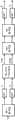
图1包括示出了根据背景技术的基于QMF的解码器的两个一般化的框图;Figure 1 includes two generalized block diagrams illustrating QMF-based decoders according to the background art;
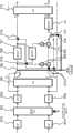
图2是根据本发明实施例的具有复数预测的基于MDCT的立体声解码器系统的一般化的框图,其中在频域中计算要解码的信号的声道的复数表示;2 is a generalized block diagram of an MDCT-based stereo decoder system with complex prediction, in which a complex representation of the channels of the signal to be decoded is computed in the frequency domain, according to an embodiment of the invention;
图3是根据本发明实施例的具有复数预测的基于MDCT的立体声解码器系统的一般化的框图,其中在时域中计算要解码的信的号声道的复数表示;3 is a generalized block diagram of an MDCT-based stereo decoder system with complex prediction, in which a complex representation of the signal channel to be decoded is computed in the time domain, according to an embodiment of the invention;
图4示出了图2的解码器系统的替换实施例,其中激活的TNS级的位置是可选的;Figure 4 shows an alternative embodiment of the decoder system of Figure 2 in which the location of the activated TNS stage is optional;
图5包括示出了根据本发明另一方面实施例的具有复数预测的基于MDCT的立体声编码器系统的一般化的框图;5 includes a block diagram illustrating a generalization of an MDCT-based stereo encoder system with complex prediction according to another embodiment of the invention;
图6是根据本发明实施例的具有复数预测的基于MDCT的立体声编码器的一般化的框图,其中要编码信号的声道的复数表示是基于其时域表示计算的;6 is a generalized block diagram of an MDCT-based stereo encoder with complex prediction, according to an embodiment of the invention, wherein the complex representation of the channel of the signal to be encoded is computed based on its time-domain representation;
图7示出了图6的编码器系统的替换实施例,该编码器系统也可操作于直接L/R编码模式;Figure 7 shows an alternative embodiment of the encoder system of Figure 6, which is also operable in direct L/R encoding mode;
图8是根据本发明实施例的具有复数预测的基于MDCT的立体声编码器系统的一般化框图,其中要编码信号的声道的复数表示是基于其第一频域表示计算的,其解码器系统也可以操作于直接L/R编码模式;8 is a generalized block diagram of an MDCT-based stereo encoder system with complex prediction, in which the complex representation of the channel of the signal to be encoded is calculated based on its first frequency-domain representation, and its decoder system, according to an embodiment of the invention Can also operate in direct L/R encoding mode;
图9示出了图7的编码器系统的替换实施例,该编码器系统还包括布置在编码级下游的TNS级;Figure 9 shows an alternative embodiment of the encoder system of Figure 7, further comprising a TNS stage arranged downstream of the encoding stage;
图10示出了图2和8中标记为A的部分的替换实施例;Figure 10 shows an alternative embodiment of the portion marked A in Figures 2 and 8;
图11示出了图8的编码器系统的替换实施例,该编码器系统还包括分别布置在编码级下游和上游的两个频域修改器件;Figure 11 shows an alternative embodiment of the encoder system of Figure 8, further comprising two frequency domain modification devices arranged downstream and upstream of the encoding stage, respectively;
图12为来自6个主题以96kb/s的听力测试结果的图形表示,该图示出了用于MDST频谱计算或近似的不同复杂度-质量折衷的选择,其中标记为“+”的数据点涉及隐藏的引用(hidden reference),“x”涉及3.5kHz带宽受限的参考(anchor),“*”涉及USAC传统立体声(M/S或L/R),“□”涉及利用禁止的预测系数虚部通过复数预测的MDCT域统一立体声编码(即,实值预测,不需要MDST),“■”涉及使用当前MDCT帧通过复数预测来计算MDST的近似的MDCT域统一立体声编码,“○”涉及使用当前和先前MDCT帧通过复数预测来计算MDST的近似的MDCT域统一立体声编码以及“●”涉及使用当前、前一和下一MDCT帧通过复数预测来计算MDST的MDCT域统一立体声编码;Figure 12 is a graphical representation of listening test results from 6 subjects at 96 kb/s, which shows the choice of different complexity-quality trade-offs for MDST spectrum calculation or approximation, where the data points marked with "+" Refers to hidden references (hidden reference), "x" refers to 3.5kHz bandwidth-limited references (anchor), "*" refers to USAC legacy stereo (M/S or L/R), "□" refers to using prohibited prediction coefficients The imaginary part is MDCT-domain unified stereo coding by complex prediction (i.e., real-valued prediction, no MDST is required), "■" involves MDCT-domain uniform stereo coding using the current MDCT frame to compute an approximation of the MDST by complex prediction, and "○" involves Approximate MDCT-domain unified stereo coding using the current and previous MDCT frame to calculate the MDST by complex prediction and "•" involves MDCT-domain unified stereo coding using the current, previous and next MDCT frame to calculate the MDST by complex prediction;
图13给出图12数据,但以相对于使用当前MDCT帧通过复数预测来计算MDST的近似的MDCT域统一立体声编码的差分分数的形式;Figure 13 presents the data of Figure 12, but in the form of differential fractions relative to the approximate MDCT-domain unified stereo coding using the current MDCT frame to compute the MDST by complex prediction;
图14包括示出了根据本发明实施例的解码器系统的三个实施例的一般化框图;Figure 14 includes a generalized block diagram illustrating three embodiments of a decoder system according to an embodiment of the invention;
图15是示出了根据本发明的实施例的解码方法流程图;以及Fig. 15 is a flowchart illustrating a decoding method according to an embodiment of the present invention; and
图16是示出了根据本发明的实施例的编码方法流程图。FIG. 16 is a flowchart illustrating an encoding method according to an embodiment of the present invention.
具体实施方式Detailed ways
Ⅰ、解码器系统Ⅰ. Decoder system
图2以一般化框图的形式示出了解码器系统,该解码器系统用于对包括复数预测系数α=αR+iαI的至少一个值和具有下混M和残留D声道的立体声信号的MDCT表示的比特流进行解码。所述预测系数的实部和虚部αR、αI可已被量化和/或已被联合编码。然而优选地,实部与虚部被独立地且通常以0.1的步长(无量纲数)均匀量化。用于复数预测系数的频带分辨率不必与按照MPEG标准的用于尺度因子带(scale factors band,sfb;即,使用相同MDCT量化步长和量化范围的一组MDCT线)的分辨率相同。特别地,预测系数的频带分辨率可为在心理声学上已被证实的一个,如Bark尺度。解复用器201适于从提供给其的比特流中提取这些MDCT表示和预测系数(如图中示出的控制信息部分)。的确,比仅仅复数预测系数多的控制信息可被编码在比特流中,这些控制信息例如为比特流是否以预测或非预测模式被解码的指令、TNS信息等。TNS信息可包括要由解码器系统的TNS(合成)滤波器施加的TNS参数值。如果同组TNS参数要被用于几个TNS滤波器,比如用于两个声道,那么接收以指示参数组的同一性的比特的形式的信息(而不是独立地接收这两组参数)是经济的。在适当时,例如,基于对两个可用选项的心理声学评估,是在上混级之前还是之后施加TNS的信息也可被包括在内。此外,然后,控制信息可单独地指示下混和残留信号的受限带宽。对于每个声道,在带宽限制以上的频带将不被解码,而被设置为零。在某些情况下,最高频带具有如此小能量的内容以致它们已被量化降至零。通常的做法(参考MPEG标准中的参数max_sfb)为对下混和残留信号二者采用相同的带宽限制。然而,与下混信号相比,残留信号在更大程度上具有被局部化到较低频带的能量内容。因此,通过对残留信号设置专用的上带宽限制,在不明显损失质量的情况下降低比特率是可能的。例如,这可由编码在比特流中的两个独立的max_sfb参数来控制,这两个参数一个用于下混信号,且一个用于残留信号。Figure 2 shows in the form of a generalized block diagram a decoder system for processing at least one value comprising complex prediction coefficients α = αR + iαI and a stereo signal with downmixed M and residual D channels The bitstream represented by the MDCT is decoded. The real and imaginary parts αR , αI of the prediction coefficients may have been quantized and/or jointly coded. Preferably, however, the real and imaginary parts are quantized independently and uniformly with a step size of 0.1 (dimensionless number). The band resolution for the complex prediction coefficients does not have to be the same as the resolution for the scale factors band (sfb; ie a set of MDCT lines using the same MDCT quantization step size and quantization range) according to the MPEG standard. In particular, the band resolution of the prediction coefficients may be one that has been proven in psychoacoustics, such as the Bark scale. The
在该实施例中,立体声信号的MDCT表示被分段成连续的时间帧(或时间块),该连续的时间帧(或时间块)包括固定数量的数据点(例如1024个点)、若干固定数量的数据点(例如128或1024个点)或可变数量的点中的一个。如本领域技术人员所知,MDCT被临界采样。在附图右面部分中示出的解码系统的输出是具有左L和右R声道的时域立体声信号。反量化模块202适于处理输入到解码系统的比特流,或在适当时,处理在解复用初始比特流后获取的且对应下混和残留声道中的每一个的两个比特流。反量化的声道信号被提供给可以操作于通过模式或求和与求差模式的切换组件203,其中通过模式和求和与求差模式所对应的各自的变换矩阵如下:In this embodiment, the MDCT representation of the stereo signal is segmented into consecutive time frames (or time blocks) comprising a fixed number of data points (e.g. 1024 points), a number of fixed One of a number of data points (e.g. 128 or 1024 points) or a variable number of points. As is known to those skilled in the art, the MDCT is critically sampled. The output of the decoding system shown in the right part of the figure is a time-domain stereo signal with left L and right R channels. The inverse quantization module 202 is adapted to process the bitstream input to the decoding system or, where appropriate, the two bitstreams obtained after demultiplexing the initial bitstream and corresponding to each of the downmixed residual channels. The dequantized channel signal is provided to the
以及as well as
如在下一段中将进一步地讨论的,解码器系统包括第二切换组件205。如同在本实施例和要描述的实施例中的大多数其他切换装置和切换组件那样,切换组件203、205均可以频率选择的方式来操作。这使得能够解码多种解码模式,例如,如相关技术中所知的,对频率依赖的L/R或M/S解码进行解码。因此,根据本发明的解码器可被认为是对于相关技术的超集。As will be discussed further in the next paragraph, the decoder system includes a
假设切换组件203现在处于通过模式,在本实施例中,反量化声道信号被通过各自的TNS滤波器204。TNS滤波器204对解码系统操作来说不是必要的,并可用通过(pass-through)元件来替代。此后,该信号提供给第二切换组件205,第二切换组件205具有与位于上游的切换组件203相同的功能性。利用前述输入信号并利用设置为通过模式的第二切换组件205,前者的输出为下混声道信号和残留声道信号。仍由其时间连续MDCT频谱来表示的下混信号被提供给实-到-虚变换206,该实-到-虚变换206适于基于该下混信号来计算其MDST频谱。在本实施例中,一个MDST帧基于三个MDCT帧:一个先前帧、一个当前(或同时)帧和一个随后帧。以符号(Z-1,Z)来指示实-到-虚变换206的输入侧包括延迟部件。Assuming that the
从实-到-虚变换206获得的下混信号的MDST表示由预测系数的虚部αI来加权,并加到下混信号的由预测系数的实部αR加权的MDCT表示并加到残留信号的MDCT表示。这两个加法和乘法由一起形成(功能上)加权加法器的乘法器和加法器210、211来执行,其被提供有最初由解码器系统接收的在比特流中编码的复数预测系数α值。复数预测系数可对每个时间帧被确定一次。其还可被更频繁地确定,诸如为一帧内的每个频带确定一次,其中频带为在心理声学上促进的划分。其还可不那么频繁地被确定,如以下关于根据本发明的编码系统将讨论的。实-到-虚变换206以如下的方式与加权加法器同步:使得下混声道信号的当前MDST帧与下混声道信号和残留声道信号中的每一信号的一个同时的MDCT帧合并。这三个信号的和是侧边信号S=Re{αM}+D。在该表达式中,M包括下混信号的MDCT和MDST表示,即M=MMDCT-iMMDST,而D=DMDCT是实数值的。因此,获得了具有下混声道和侧边声道的立体声信号,根据该立体声信号,求和与求差变换如下恢复左和右声道:The MDST representation of the downmix signal obtained from the real-to-
这些信号被表示在MDCT域中。解码系统最后的步骤是将逆MDCT 209施加到每个声道,借此获得左/右立体声信号的时域表示。These signals are represented in the MDCT domain. The final step in the decoding system is to apply an inverse MDCT 209 to each channel, thereby obtaining a time-domain representation of the left/right stereo signal.
在上面所提及的申请人的专利US 6,980,933B2中进一步描述了实-到-虚变换206的可能实施方式。通过其中的公式41,变换可被表示为有限脉冲响应滤波器,例如,对于偶数点,A possible implementation of the real-to-
其中,S(2v)是第2v个MDST数据点,XI、XII、XIII是来自每个帧的MDCT数据,以及N是帧长。此外,hI,III、hII是依赖于施加的窗函数的脉冲响应,并因此针对每次窗函数的选择(诸如矩形窗函数、正弦窗函数和凯撒-贝塞尔衍生窗函数)且针对每个帧长而被确定。通过省去具有相对较小的能量内容且对MDST数据贡献相对较少的那些脉冲响应,可降低该计算的复杂度。作为该简化的替换或扩展,脉冲响应本身可被缩短,例如从完整帧长N缩短到较少数量的点。例如,脉冲响应长度可从1024点(抽头)减少到10点。仍能被认为有意义的最极端的截短是:where S(2v) is the 2vth MDST data point, XI , XII , XIII are the MDCT data from each frame, and N is the frame length. Furthermore, hI, III , hII are impulse responses dependent on the applied window function, and thus for each choice of window function (such as rectangular, sinusoidal, and Kaiser-Bessel-derived window functions) and for Each frame length is determined. The complexity of this calculation can be reduced by leaving out those impulse responses that have relatively small energy content and contribute relatively little to the MDST data. As an alternative or extension to this simplification, the impulse response itself can be shortened, eg from a full frame length N to a smaller number of points. For example, the impulse response length can be reduced from 1024 points (taps) to 10 points. The most extreme truncations that can still be considered meaningful are:
S(v)=XII(v+1)-XII(v-1)。S(v)=XII (v+1)-XII (v-1).
其他直接的方法可在US 2005/0197831A1中找到。Other straightforward methods can be found in US 2005/0197831A1.
还可减少计算所基于的输入数据量。为了说明,实-到-虚变换206和其上游连接(在附图上被示出为由“A”表示的部分)由简化变形来代替,简化变形中的两个A'和A"在图10中示出。变形A'提供信号的近似虚数表示。这里,MDST计算仅考虑当前帧和前一帧。参考上面的公式,在本段中,这可通过设置XIII(p)=0来实现,p=0,...,N-1(下标III表示随后的时间帧)实现。因为变形A'不要求随后帧的MDCT频谱作为输入,所以MDST计算不会引起任何延迟。明显地,该近似有些降低了所获得MDST信号的精确度,但也可意味着该信号的能量变低;作为预测编码特性的结果,后一事实可通过提高αI来完全补偿。It also reduces the amount of input data on which calculations are based. For illustration, the real-to-
在图10中也示出了变形A",该变形只使用当前时间帧的MDCT数据作为输入。可论证地,变形A"产生比变形A'更不精确的MDST表示。另一方面,就像变形A'一样,变形A"以零延迟来操作,并具有较低的计算复杂性。如已经提到的,只要在编码器系统和解码器系统中使用相同的近似,波形编码特性就不会受到影响。Also shown in Fig. 10 is variant A", which uses only the MDCT data of the current time frame as input. Arguably, variant A" produces a less accurate MDST representation than variant A'. On the other hand, just like variant A', variant A" operates with zero delay and has low computational complexity. As already mentioned, as long as the same approximation is used in both the encoder system and the decoder system, Waveform encoding characteristics will not be affected.
需要注意的是,不管使用变形A、A'或A"或其任何更进一步的演进,只有复数预测系数的虚部非零(αI≠0)的MDST频谱的那些部分需要计算。在实际情况中,这可被认为是系数虚部的绝对值|αI|大于预设门限值,这可能与所使用的硬件的四舍五入单元(unit round-off)有关。如果系数虚部对于时间帧内的所有频带都是零,则不需要为该帧计算任何MDST数据。因此,适当地,实-到-虚变换206适于通过不产生MDST输出来响应非常小的|αI|值的出现,借此可节约计算资源。但是,在使用比当前帧更多的帧来产生一帧MDST数据的实施例中,即使不需要MDST频谱,变换206上游的任何单元都应适当地连续操作——特别地,第二切换组件205应该持续前转MDCT频谱——以便当与非零预测系数有关的下一时间帧出现时,实-到-虚变换206已经可获得足够的输入数据;当然这可为下一个时间块。It should be noted that regardless of the use of variants A, A' or A" or any further evolution thereof, only those parts of the MDST spectrum for which the imaginary part of the complex prediction coefficients are non-zero (αI ≠ 0) need to be computed. In practice In , this can be considered as the absolute value of the imaginary part of the coefficient |αI | is greater than the preset threshold value, which may be related to the rounding unit (unit round-off) of the hardware used. If the imaginary part of the coefficient is for the time frame If all frequency bands are zero, no MDST data needs to be calculated for the frame. Therefore, suitably, the real-to-
返回到图2,在两个切换组件203、205被设置为其各自通过模式的假设下,解码系统的功能已被描述。如现在将讨论的,解码器系统还可对未被预测编码的信号解码。对于该使用,第二切换组件205将被设置在其求和与求差模式,并且如附图上所示,选择器装置208将被适当地设置在其较低位置中,从而保证信号从TNS滤波器204和第二切换组件205之间的源点直接馈给到逆变换209。为了保证正确解码,在源点处,该信号适当地具有L/R形式。因此,为保证实-到-虚变换被一直提供一正确的中间(即,下混)信号(而不是间歇地被提供以左信号),在对非预测编码立体声信号进行解码期间,第二切换组件205被优选地设置于其求和与求差模式。如上面所指出的,基于例如数据速率到音频质量的判决,对于某些帧,预测编码可由传统的直接或联合编码来代替。这种判决的结果可以用多种方式从编码器传送到解码器,例如,通过每帧中专用指示比特的值来传送,或通过预测系数值的不存在或存在来传送。在确立了这些事实的情况下,第一切换组件203的作用就可被容易地理解了。的确,在非预测编码模式中,解码器系统可处理按照直接(L/R)立体声编码或联合(M/S)编码的信号,并且通过使第一切换组件操作于通过模式或求和与求差模式,能够保证源点总被提供有直接编码信号。清楚地,当用作求和与求差级时,切换组件203将M/S形式的输入信号转换成以L/R形式的输出信号(提供给可选的TNS滤波器204)。Returning to Figure 2, the functionality of the decoding system has been described under the assumption that the two switching
该解码器系统接收是否以预测编码或非预测编码模式由解码器系统对特定时间帧解码的信号。非预测模式可通过每帧中专用指示位的值或通过预测系数的不存在(或零值)来指示。预测模式可类似地传送。一种特别有益的实施方式(其在没有任何开销的情况下实现回退(fallback))利用两比特字段ms mask present(见MPEG-2AAC,ISO/IEC13818-7文件)中被保留的第四个值,该字段在每一时间帧被传输并被定义如下:The decoder system receives a signal whether a particular time frame is decoded by the decoder system in a predictively encoded or non-predictively encoded mode. Non-prediction modes can be indicated by the value of a dedicated indicator bit in each frame or by the absence (or zero value) of prediction coefficients. Predictive modes can be communicated similarly. A particularly beneficial implementation (which implements fallback without any overhead) utilizes the reserved fourth value, this field is transmitted every time frame and is defined as follows:

通过将值11重新定义为指“复数预测编码”,解码器能够操作于所有已有模式,特别是M/S和L/R编码,而没有任何比特-速率损失,并仍然能够接收用于指示有关帧的复数预测编码模式的信号。By redefining the value 11 to mean "complex predictive coding", the decoder is able to operate in all existing modes, in particular M/S and L/R coding, without any bit-rate loss, and still be able to receive Signal about the complex predictive coding mode of the frame.
图4示出了具有与图2示出的结构相同的通用结构的解码器系统,但是包括至少两个不同的结构。首先,图4的系统包括切换装置404、411,切换装置404和411使得能够施加涉及上混级的上游和/或下游的频域修改的一些处理步骤。一方面,这由第一组频域修改器403(本图中被示出为TNS合成滤波器)来实现,该第一组频域修改器403连同第一切换装置404一起被提供在反量化模块401和第一切换组件402下游,但是在第二切换组件405的上游,第二切换组件405紧接地布置在上混级406、407、408、409上游。另一方面,解码器系统包括第二组频域修改器410,第二组频域修改器410与第二切换装置411一起提供在上混级406、407、408、409的下游,但在逆变换级412的上游。有益地,如图中所示,每个频域修改器被布置为与通过线并联,其中通过线向上游连接到频域修改器的输入侧,并向下游连接到关联的切换装置。借助于该结构,频域修改器被一直提供有信号数据,使得能够在频域中基于比仅仅当前时间帧更多的时间帧来进行处理。施加第一组频域修改器403还是第二组频域修改器410的决定可由编码器做出(并在比特流中传达),或可基于预测编码是否施加,或可基于一些其他在实际情况中发现合适的准则。例如,如果频域修改器是TNS滤波器,则对于某些类型的信号,第一组频域修改器403可能是有利的,而第二组频域修改器410可能对于其他种类的信号是有利的。如果该选择的结果被编码在比特流中,则解码器系统将相应地激活相应组的TNS滤波器。Fig. 4 shows a decoder system having the same general structure as that shown in Fig. 2, but including at least two different structures. Firstly, the system of Fig. 4 comprises switching means 404, 411 enabling to apply some processing steps involving frequency domain modification upstream and/or downstream of the upmixing stage. On the one hand, this is achieved by a first set of frequency-domain modifiers 403 (shown in this figure as TNS synthesis filters), which together with a first switching means 404 are provided at the inverse quantization Downstream of the module 401 and the first switching assembly 402 , but upstream of the second switching assembly 405 which is arranged immediately upstream of the upmixing stages 406 , 407 , 408 , 409 . On the other hand, the decoder system comprises a second set of frequency domain modifiers 410 provided downstream of the upmixing stages 406, 407, 408, 409, but inversely upstream of transform stage 412 . Advantageously, as shown in the figures, each frequency domain modifier is arranged in parallel with a via line connected upstream to the input side of the frequency domain modifier and downstream to the associated switching means. With this structure, the frequency domain modifier is always supplied with signal data, enabling processing in the frequency domain based on more time frames than just the current time frame. The decision to apply the first set of frequency-domain modifiers 403 or the second set of frequency-domain modifiers 410 may be made by the encoder (and communicated in the bitstream), or may be based on whether predictive encoding is applied, or may be based on some other real-world situation Appropriate criteria are found in . For example, if the frequency domain modifiers are TNS filters, a first set of frequency domain modifiers 403 may be beneficial for certain types of signals, while a second set of frequency domain modifiers 410 may be beneficial for other kinds of signals of. If the result of this selection is encoded in the bitstream, the decoder system will activate the corresponding set of TNS filters accordingly.
为了便于理解图4示出的解码器系统,需要明确注意的是,直接(L/R)编码的信号的解码在α=0时(隐含伪-L/R和L/R是相同的且侧边和残留声道没有不同)发生,第一切换组件402处于通过模式,第二切换组件处于求和与求差模式,从而使信号在第二切换组件405和上混级的求和与求差级409之间具有M/S形式。因为然后上混级将实际上作为通过步骤,所以是否激活(使用各自的切换装置404、411)第一或第二组频域修改器是不重要的。To facilitate the understanding of the decoder system shown in Fig. 4, it is explicitly noted that the decoding of a directly (L/R) encoded signal occurs when α = 0 (implied pseudo-L/R and L/R are identical and side and residual channels) occur, the first switching component 402 is in the pass-through mode, and the second switching component is in the summing and subtracting mode, so that the signal is summed and summed in the second switching component 405 and the upmixing stage There is an M/S form between the differential stages 409 . It does not matter whether the first or second set of frequency domain modifiers is activated (using the respective switching means 404, 411 ) since then the upmixing stage will actually act as a pass-through step.
图3说明了根据本发明实施例的解码器系统,与图2和4相比,图3的系统代表提供上混所需MDST数据的不同方法。如同已描述的解码器系统,图3的系统包括反量化模块301、可以操作于通过或求和与求差模式的第一切换组件302和TNS(合成)滤波器303,这些组件都从解码器系统输入端开始串联布置。该点下游的模块通过两个第二切换装置305、310而被选择性地采用,如图中所示,两个第二切换装置305、310优选地被联合操作使得两者都处于其较高位置或都处于其较低位置。在解码器系统输出端,有求和与求差级312,紧接其上游的是用于将每个声道的MDCT域表示变换成时域表示的两个逆MDCT模块306、311。Figure 3 illustrates a decoder system according to an embodiment of the present invention, the system of Figure 3 represents a different approach to providing the MDST data required for upmixing compared to Figures 2 and 4 . As with the decoder system already described, the system of Fig. 3 includes an inverse quantization module 301, a
在复数预测解码中,其中解码器系统被提供以编码有下混/残留立体声信号和复数预测系数的值的比特流,第一切换组件302被设置为其通过模式,且第二切换装置305、310被设置在较高位置。在TNS滤波器下游,(反量化的、TNS滤波的、MDCT)立体声信号的两个声道被以不同方式处理。一方面,该下混声道被提供给乘法器和求和器308,该乘法器和求和器308将由预测系数的实部αR加权的下混声道的MDCT表示加到残留声道的MDCT表示,而另一方面,该下混声道被提供给逆MDCT变换模块中的一个306。从逆MDCT变换模块306输出的下混声道M的时域表示被提给最后的求和与求差级312和MDST变换模块307。从计算复杂性角度看,两次使用下混声道的时域表示是有利的。因此获得的下混声道的MDST表示被提供给另外的乘法器和求和器309,该乘法器和求和器309将下混声道的MDST表示用预测系数的虚部αI加权后,将该信号加到来自求和器308的线性组合输出;因此,求和器309的输出是侧边声道信号,S=Re{αM}+D。与图2示出的解码器系统类似,乘法器和求和器308、309可被容易地结合,以形成输入为下混信号的MDCT和MDST表示、残留信号的MDCT表示和复数预测系数值的加权多信号加和器。本实施例中,在该点下游,在侧边声道信号被提供给最后的求和与求差级312前,只有通过逆MDCT变换模块311的声道保留下来。In complex predictive decoding, where the decoder system is provided with a bitstream encoded with the downmix/residual stereo signal and the values of the complex prediction coefficients, the
如已在频率选择性M/S和L/R编码中实践的,通过在两个逆MDCT变换模块306、311施加相同的变换长度和窗口形状,可实现解码器系统中的必要的同步性。通过将逆MDCT模块306的某些实施例与MDST模块307的实施例组合,单帧延迟被引入。因此,五个可选的延迟模块313(或在计算机实现中,起该作用的软件指令)被提供,使得必要时系统的位于虚线右边的部分与左边部分相比可延迟一帧。显然地,除逆MDCT模块306和MDST变换模块307之间的连接线(为发生需要补偿的延迟的位置)之外,虚线和连接线之间的所有交点被提供有延迟模块。By applying the same transform length and window shape at the two inverse MDCT transform
对于一个时间帧的MDST数据的计算需要来自一帧的时域表示的数据。然而,逆MDCT变换基于一帧(当前帧)、两个连续帧(优选地:前一帧和当前帧)或三个连续帧(优选地:前一帧、当前帧和后一帧)。借助于众所周知的与MDCT有关的时域混叠消除(time-domain aliascancellation,TDAC),至少在包含时域混叠的帧中,三帧的选项实现了输入帧的完全重叠,并因此提供最好的(且可能是完美的)准确度。明显地,三帧逆MDCT以单帧延迟操作。通过接受使用近似时域表示作为到MDST变换的输入,可避免该延迟,并且从而避免在解码器系统不同部分间补偿延迟的需要。在两帧的选项中,支持TDAC的重叠/增加出现在帧的较早一半中,且混叠仅在较晚的一半中出现。在单帧选项中,没有TDAC意味着混叠可贯穿帧而发生;然而,以此方式实现的并用作复数预测编码中的中间信号的MDST表示仍可提供令人满意的质量。Computation of MDST data for a time frame requires data from a time domain representation of a frame. However, the inverse MDCT transform is based on one frame (current frame), two consecutive frames (preferably: previous frame and current frame) or three consecutive frames (preferably: previous frame, current frame and subsequent frame). With the well-known time-domain aliasing cancellation (TDAC) associated with MDCT, the three-frame option achieves a complete overlap of the input frames, at least in frames containing time-domain aliasing, and thus provides the best (and possibly perfect) accuracy. Clearly, the three-frame inverse MDCT operates with a single-frame delay. By accepting the use of an approximate time-domain representation as input to the MDST transform, this delay, and thus the need to compensate for delays between different parts of the decoder system, can be avoided. In the two-frame option, TDAC-enabled overlap/increase occurs in the earlier half of the frame, and aliasing only occurs in the later half. In the single frame option, the absence of TDAC means that aliasing can occur throughout the frame; however, the MDST representation implemented in this way and used as an intermediate signal in complex predictive coding still provides satisfactory quality.
图3中示出的解码系统也可以操作于两种非预测解码模式。为了对直接L/R编码的立体声信号进行解码,第二切换装置305、310被设置在较低位置,且第一切换组件302被设置为通过模式。因此,信号在求和与求差级304上游具有L/R形式,求和与求差级304将其转换成M/S形式,在此基础上,进行逆MDCT变换和最后的求和与求差操作。为了对以联合M/S编码形式提供的立体声信号进行解码,相反地,第一切换组件302被设置为其求和与求差模式,使得信号在第一切换组件302和求和与求差级304之间具有L/R形式,其从TNS滤波角度看经常比M/S形式更合适。求和与求差级304下游的处理与在直接L/R解码的例子中的相同。The decoding system shown in Figure 3 can also operate in two non-predictive decoding modes. For decoding a direct L/R encoded stereo signal, the second switching means 305, 310 are set in a lower position and the
图14包括示出了根据本发明的各实施例的解码器的三个一般化的框图。与伴随本申请的几个其他框图相比,图14中的连接线可代表多声道信号。特别地,这种连接线可布置为传输包括左/右、中间/侧边、下混/残留、伪左/伪右声道以及其他组合的立体声信号。Figure 14 includes three generalized block diagrams illustrating decoders according to various embodiments of the invention. In contrast to several other block diagrams accompanying this application, the connecting lines in Figure 14 may represent multi-channel signals. In particular, such connecting lines may be arranged to transmit stereo signals including left/right, mid/side, downmix/residue, pseudo left/pseudo right channels, and other combinations.
图14A示出了用于对输入信号的频域表示(为了本图的目的,被示出为MDCT表示)进行解码的解码器系统。该解码器系统适于提供作为其输出的立体声信号的时域表示,其基于输入信号来生成。为了能够解码通过复数预测立体声来编码的已编码输入信号,解码器系统被提供有上混级1410。然而,其也能够处理以其他格式编码的、以及可能在时间上在几个编码模式间交替编码的输入信号,例如,由复数预测编码所编码的时间帧序列可跟随着由直接左/右编码所编码的时间部分。通过提供与所述上混级1410并行布置的连接线(通过),可实现解码器系统处理不同编码格式的能力。利用切换装置1411,可选择是(图中较低切换位置)将来自上混级1410的输出提供给被进一步布置在下游的解码器模块,还是(图中较高切换位置)将在连接线上可获得的未处理信号提供给被进一步布置在下游的解码器模块。在该实施例中,逆MDCT模块1412被布置在切换装置下游,其将信号MDCT表示变换成时域表示。例如,提供给上混级1410的信号可为下混/残留形式的立体声信号。然后,上混级1410适于导出侧边信号,并执行求和与求差操作,以使得左/右立体声信号(在MDCT域)为输出。Figure 14A shows a decoder system for decoding a frequency-domain representation of an input signal (shown as an MDCT representation for the purposes of this figure). The decoder system is adapted to provide as its output a time-domain representation of the stereo signal, which is generated based on the input signal. In order to be able to decode an encoded input signal encoded by complex predictive stereo, the decoder system is provided with an
图14B示出了与图14A类似的解码器系统。该系统适于在其输入信号处接收比特流。该比特流被组合的解复用器和反量化模块1420初始处理,模块1420提供待进一步处理的多声道立体声信号的MDCT表示,作为第一输出信号,进一步的处理由具有与图14A的切换装置1411相似的功能性的切换装置1422的位置来确定。更确切地说,切换装置1422确定来自解复用器和反量化的第一输出是由上混级1421和逆MDCT模块1423处理(较低位置),还是仅由逆MDCT模块1423处理(较高位置)。组合的解复用器和反量化模块1420还输出控制信息。在本例子中,与立体声信号有关的控制信息可包括:指示切换装置1422的较高位置还是较低位置适合于解码信号(或更抽象地,按照什么编码格式将该立体声信号解码)的数据。控制信息还可包括用于调节上混级1421特性的参数,例如,用于已在上面描述的复数预测编码中的复数预测系数α的值。Figure 14B shows a decoder system similar to that of Figure 14A. The system is adapted to receive a bit stream at its input signal. This bitstream is initially processed by the combined demultiplexer and
图14C示出了一种解码器系统,除与图14B中相似的实体之外,该解码器系统还包括分别布置在上混级1433上游和下游的第一和第二频域修改器件1431、1435。为了该图的目的,每个频域修改器件由TNS滤波器示出。然而,该术语频域修改器件也可被理解为易于在上混级前或后施加的其他处理(不是TNS滤波)。频域修改的示例包括预测、噪音增加、带宽扩展和非线性处理。心理声学考虑因素和类似理由(可能包括要被处理的信号的特性和/或这种频域修改器件的配置或设置),有时指示将所述频域修改施加在上混级1433上游而非下游是有利的。在其他情况下,通过类似考虑,可确定频域修改的下游位置优于上游位置。利用切换装置1432、1436,可选择性地激活频域修改器件1431、1435,使得响应于控制信息,解码器系统能够选择想要的配置。例如,图14C示出一种配置,其中来自组合的解复用器和反量化模块1430的立体声信号最初由第一频域修改装置1431处理,然后被提供给上混级1433,并最后直接前转到逆MDCT模块1437,而不经过第二频域修改装置1435。如发明内容部分所解释的,在复数预测编码中,相对于在上混后执行TNS的选项,该配置是优选的。Figure 14C shows a decoder system comprising, in addition to entities similar to those in Figure 14B, first and second frequency-
II、编码器系统II. Encoder system
现在将参考图5描述根据本发明的编码器系统,图5是用于通过复数预测编码对左/右(L/R)立体声信号进行编码作为输出比特流的编码器系统的一般化框图。该编码器系统接收信号的时域或频域表示,并将其提供给下混级和预测系数估计器。预测系数的实部与虚部被提供给下混级,以便控制左和右声道到下混和残留声道的转换,然后下混和残留声道被提供给最后的复用器MUX。如果信号没有被作为频域表示提供给编码器,那么,其在下混级或复用器中被转换成这种表示。An encoder system according to the invention will now be described with reference to Fig. 5, which is a generalized block diagram of an encoder system for encoding a left/right (L/R) stereo signal as an output bitstream by complex predictive coding. The encoder system receives a time-domain or frequency-domain representation of the signal and provides it to a downmix stage and a prediction coefficient estimator. The real and imaginary parts of the prediction coefficients are supplied to the downmix stage in order to control the conversion of the left and right channels to the downmix and residual channels, which are then supplied to the final multiplexer MUX. If the signal is not provided to the encoder as a frequency domain representation, it is converted to such a representation in a downmix stage or multiplexer.
预测编码中的原理之一是将左/右信号转换为中间/侧边形式,即,One of the principles in predictive coding is to transform the left/right signal into a mid/side form, i.e.,
然后,利用这些声道之间保留的相关度,即通过设置:Then, use the preserved correlation between these channels, i.e. by setting:
S=Re{αM}+D,S=Re{αM}+D,
其中α是要确定的复数预测系数,且D是残留信号。可以选择α,使得残留信号D=S-Re{αM}的能量最小化。可相对于瞬时功率、较短期能量或较长期能量(功率平均值)来实现能量最小化,其就离散信号而言,等于均方意义下的最优化。where α is the complex prediction coefficient to be determined and D is the residual signal. α can be chosen such that the energy of the residual signal D=S-Re{αM} is minimized. Energy minimization can be achieved with respect to instantaneous power, shorter-term energy, or longer-term energy (power average), which is equivalent to optimization in the mean square sense for discrete signals.
预测系数的实部与虚部αR、αI可被量化和/或联合编码。然而,优选地,实部与虚部被独立地且均匀地量化,通常以0.1步长(无量纲数)来量化。用于复数预测系数的频带分辨率不必与按照MPEG标准的用于尺度因子带(scale factors band,sfb;即,使用相同MDCT量化步长和量化范围的一组MDCT线)的分辨率相同。特别地,预测系数的频带分辨率可为在心理声学上已被证实的一个,如Bark尺度。需要注意的是,在变换长度改变的情况下,频带分辨率可改变。The real and imaginary parts αR , αI of the prediction coefficients may be quantized and/or jointly coded. Preferably, however, the real and imaginary parts are quantized independently and uniformly, typically in steps of 0.1 (dimensionless number). The band resolution for the complex prediction coefficients does not have to be the same as the resolution for the scale factors band (sfb; ie a set of MDCT lines using the same MDCT quantization step size and quantization range) according to the MPEG standard. In particular, the band resolution of the prediction coefficients may be one that has been proven in psychoacoustics, such as the Bark scale. It should be noted that in case the transform length is changed, the band resolution may be changed.
如已经指出的,根据本发明的编码器系统可具有是否施加预测立体声编码的选择余地。不施加预测立体声编码的情况意味着回退到L/R或M/S编码。这样的决定可基于时间帧做出,或更精细地,基于时间帧内的频带做出。如上面所指出的,否定的决定结果可以用多种方式传递到解码器实体,例如,通过每帧中的专用指示位的值,或通过预测系数值的不存在(或零值)。肯定的决定可被类似地传递。一种特别有益的实施方式(其在没有任何开销的情况下实现回退(fallback))利用两比特字段ms_mask_present(见MPEG-2AAC,ISO/IEC13818-7文件)中被保留的第四个值,该字段在每一时间帧被传输并被定义如下:As already indicated, the encoder system according to the invention may have the option of applying predictive stereo encoding or not. The case of not applying predictive stereo coding means falling back to L/R or M/S coding. Such a decision may be made based on a time frame, or more finely, a frequency band within a time frame. As indicated above, a negative decision result can be communicated to the decoder entity in various ways, eg by the value of a dedicated indicator bit in each frame, or by the absence (or zero value) of a prediction coefficient value. Affirmative decisions can be similarly communicated. A particularly beneficial implementation (which implements fallback without any overhead) utilizes a fourth value reserved in the two-bit field ms_mask_present (see MPEG-2AAC, ISO/IEC13818-7 document), This field is transmitted every time frame and is defined as follows:

通过将值11重新定义为指“复数预测编码”,编码器可以操作于所有已有模式,特别是M/S和L/R编码,没有任何比特-速率损失,并仍然能够指示对于复数预测编码对其有利的那些帧进行复数预测编码。By redefining the value 11 to refer to "complex predictive coding", the encoder can operate in all existing modes, in particular M/S and L/R coding, without any bit-rate loss, and still be able to indicate that for complex predictive coding Those frames for which it is beneficial are complex predictively coded.
实质的决定可基于数据速率到音频质量的基本原理。作为质量的量度,可使用通过利用包括在编码器(通常的情况是可用的基于MDCT的音频编码器)内的心理声学模型而获得的数据。特别地,编码器的一些实施例提供了预测系数的速率-畸变的优化选择。因此,在这样的实施例中,如果预测增益的增加没有为残留信号的编码节省出足够的比特,则预测系数的虚部(并且可能还有实部)被设置为零,以调整使用对预测系数进行编码所需的比特。Substantial decisions can be based on rationale from data rate to audio quality. As a measure of quality, data obtained by utilizing a psychoacoustic model included in an encoder (often the case of available MDCT-based audio encoders) can be used. In particular, some embodiments of the encoder provide for a rate-distortion optimized choice of the prediction coefficients. Therefore, in such an embodiment, if the increase in prediction gain does not save enough bits for the coding of the residual signal, the imaginary part (and possibly also the real part) of the prediction coefficients is set to zero to adjust the use of the prediction The bits required to encode the coefficients.
编码器的实施例可将比特流中关于TNS的信息进行编码。这样的信息可包括要通过解码器侧的TNS(合成)滤波器而施加的TNS参数的值。如果同一组的TNS参数要被用于两个声道,那么,包括用于指示参数组的同一性的信令比特(而不是独立地传输这两组参数)是经济的。在适当时,例如,基于对两个可用选项的心理声学评估,是在上混级之前还是之后施加TNS的信息也可被包括在内。An embodiment of the encoder may encode information about the TNS in the bitstream. Such information may include values of TNS parameters to be applied by a TNS (synthesis) filter on the decoder side. If the same set of TNS parameters is to be used for both channels, it is economical to include a signaling bit to indicate the identity of the parameter set (instead of transmitting the two sets of parameters independently). Information on whether TNS is applied before or after upmixing may also be included where appropriate, eg based on a psychoacoustic assessment of the two available options.
作为从复杂度和比特率角度来看潜在有利的又一可选特征,编码器可适于对残留信号的编码采用单独的受限带宽。在该限制以上的频带将不被传输到解码器,而被设置为零。在某些情况下,最高频带具有如此小能量的内容,以致它们已被量化降至零。通常的做法(参考MPEG标准中的参数max_sfb)要求对下混和残留信号采用相同的带宽限制。现在,发明人通过经验已经发现,与下混信号相比,残留信号在更大程度上使其能量内容被局部化在较低频带。因此,通过对残留信号设置专用的上带宽限制,在不明显损失质量的情况下,比特率的降低是可能的。例如,这可通过发送两个独立的max_sfb参数(一个用于下混信号且一个用于残留信号)来实现。As yet another optional feature potentially advantageous from a complexity and bit rate perspective, the encoder may be adapted to employ a separate restricted bandwidth for the encoding of the residual signal. Bands above this limit will not be transmitted to the decoder, but will be set to zero. In some cases the highest frequency bands have such a small energy content that they have been quantized down to zero. Common practice (see parameter max_sfb in the MPEG standard) requires the same bandwidth limitation for downmix and residual signals. The inventors have now found empirically that the residual signal has its energy content localized in the lower frequency bands to a greater extent than the downmix signal. Thus, bitrate reduction is possible without appreciable loss of quality by placing a dedicated upper bandwidth limit on the residual signal. For example, this can be achieved by sending two separate max_sfb parameters, one for the downmix signal and one for the residual signal.
需要指出的是,尽管参考图5中示出的解码器系统讨论了预测系数的最优确定、其量化和编码、回退到M/S或L/R模式、TNS滤波和带宽上限等问题,相同的事实同样地适用于参考随后附图在以下描述中公开的实施例。It should be noted that although issues such as optimal determination of prediction coefficients, their quantization and encoding, fallback to M/S or L/R modes, TNS filtering and bandwidth capping are discussed with reference to the decoder system shown in Fig. 5, The same fact applies equally to the embodiments disclosed in the following description with reference to the accompanying drawings.
图6示出了根据本发明的又一编码器系统,其适于执行复数预测立体声编码。该系统接收作为输入的、被分段为连续的、可能重叠的时间帧并包括左和右声道的立体声信号的时域表示。求和与求差级601将该信号转换成中间和侧边声道。中间声道被提供给MDCT模块602和MDST模块603,而侧边声道仅提供给MDCT模块604。如上面所解释的,预测系数估计器605为每个时间帧(以及可能地为帧内各个频带)估计复数预测系数α的值。系数α的值被作为权重提供给加权求和器606、607,加权求和器606、607将残留信号D形成为中间信号的MDCT和MDST表示和侧边信号的MDCT表示的线性组合。优选地,复数预测系数被提供给由与其被编码成比特流时使用的相同的量化方案所表示的加权求和器606、607;因为编码器和解码器都施加相同的预测系数值,所以,这明显地提供了更可靠的重建。残留信号、中间信号(当其与残留信号一起出现时可被更适当地称为下混信号)和预测系数被提供给组合的量化和复用器级608,量化和复用器级608对这些以及可能的附加信息进行编码,作为输出比特流。Fig. 6 shows a further encoder system according to the invention, adapted to perform complex predictive stereo encoding. The system receives as input a time domain representation of a stereo signal segmented into consecutive, possibly overlapping time frames and comprising left and right channels. The summation and
图7示出了图6编码器系统的变形。如从图中标记的相似性来看,很清楚其具有类似的结构,但也具有增加的操作于直接L/R编码回退模式的功能性。通过被提供在紧接组合的量化和复用器级709上游的切换装置710,编码器系统在复数预测编码模式和回退模式之间驱动。如图中所示,在其较高位置,切换装置710将使得编码器以回退模式操作。从位于MDCT模块702、704紧接下游的点处,中间/侧边信号被提供给求和与求差级705,该求和与求差级705在将信号转换成左/右形式后,将其继续传送到切换装置710,该切换装置710将其连接到组合的量化和复用器级709。FIG. 7 shows a variation of the encoder system of FIG. 6 . As seen from the similarity of labeling in the figures, it is clear that it has a similar structure, but also has the added functionality of operating in a direct L/R coded fallback mode. By switching means 710 provided immediately upstream of the combined quantizer and
图8示出了根据本发明的一种编码器系统。与图6与7的编码器系统对比,该实施例直接从MDCT数据中导出复数预测编码所需的MDST数据,即,通过频域中的实到虚的变换来导出复数预测编码所需的MDST数据。实到虚的变换应用任何参考图2和4的解码器系统讨论的方法。重要的是将解码器的计算方法与编码器的匹配,使得能够实现可靠的解码;优选地,相同的实到虚的变换方法用在编码器侧和解码器侧上。对于解码器实施例,由虚线包围并包括实到虚的变换804的部分A可用近似变形来代替,或使用更少的时间帧作为输入。同样地,使用如上所述的其他近似方法中的任何一个,可使编码简化。Figure 8 shows an encoder system according to the invention. Compared with the encoder systems in Figures 6 and 7, this embodiment directly derives the MDST data required for complex predictive coding from the MDCT data, that is, derives the MDST data required for complex predictive coding through real-to-imaginary transformation in the frequency domain data. The real-to-virtual transformation applies any of the methods discussed with reference to the decoder systems of FIGS. 2 and 4 . It is important to match the calculation method of the decoder to that of the encoder so that reliable decoding can be achieved; preferably the same real-to-virtual transformation method is used on both the encoder and decoder sides. For a decoder embodiment, the part A surrounded by the dashed line and including the real-to-imaginary transformation 804 may be replaced by an approximate deformation, or using fewer time frames as input. Likewise, coding can be simplified using any of the other approximation methods described above.
在更高级别上,图8的编码器系统具有不同于图7中可能接着通过(被合适地连接的)实到虚的模块来放置MDST模块的直接动作的结构。本结构是简洁的,并以鲁棒的和计算上经济的方式实现预测编码和直接L/R编码之间切换的功能性。输入立体声信号被供给MDCT变换模块801,该模块输出每个声道的频域表示。所述频域表示被馈给最后的切换装置808(用于在编码器系统的预测和直接编码模式之间驱动编码器系统)和求和与求差级802。在直接L/R编码或联合M/S编码中(该实施例在预测系数α设置为零的时间帧中进行),其使输入信号仅经过MDCT变换、量化和复用,后两步由布置在系统输出端的组合的量化和复用器级807来实现,在系统输出端,比特流被提供。在预测编码中,每个声道都经过在求和与求差级802和切换装置808之间的进一步处理。根据中间信号的MDCT表示,实到虚的变换804推导出MDST数据,并将其前转给预测系数估计器803和加权求和器806。如同在图6和7中示出的编码器系统那样,另外的加权求和器805用于将侧边信号与加权的中间信号的MDCT和MDST表示合并,以形成残留声道信号,该残留声道信号连同中间(即,下混)声道信号和预测系数一起由组合的量化和复用器模块807来编码。At a higher level, the encoder system of FIG. 8 has a different structure than in FIG. 7 where the direct action of the MDST module may then be placed through (suitably connected) real-to-virtual modules. The present structure is concise and achieves the functionality of switching between predictive coding and direct L/R coding in a robust and computationally economical manner. The input stereo signal is fed to the MDCT transform module 801, which outputs a frequency domain representation of each channel. The frequency domain representation is fed to a final switching means 808 (for driving the encoder system between its predictive and direct encoding modes) and a summation and difference stage 802 . In direct L/R coding or joint M/S coding (this embodiment is performed in the time frame where the prediction coefficient α is set to zero), it makes the input signal only undergo MDCT transformation, quantization and multiplexing, and the latter two steps are arranged by This is achieved by a combined quantizer and multiplexer stage 807 at the system output, where the bit stream is provided. In predictive coding, each channel undergoes further processing between summation and difference stage 802 and switching means 808 . From the MDCT representation of the intermediate signal, the real-to-imaginary transform 804 derives the MDST data and forwards it to the prediction coefficient estimator 803 and the weighted summer 806 . As in the encoder systems shown in Figures 6 and 7, an additional weighted summer 805 is used to combine the side signals with the weighted MDCT and MDST representations of the mid signal to form a residual channel signal, which The channel signals are encoded by the combined quantizer and multiplexer module 807 together with the intermediate (ie downmix) channel signals and prediction coefficients.
现在转到图9,将被说明的是,编码器系统的每个实施例都可与一个或更多个TNS(分析)滤波器结合。根据前面的讨论,将TNS滤波施加到其下混形式的信号常常是有益的。因此,如图9所示,通过将TNS滤波器911增加在组合的量化和复用器模块909的紧接的上游,实现对图7的编码器系统的适配以包括TNS。Turning now to Figure 9, it will be explained that each embodiment of the encoder system can be combined with one or more TNS (analysis) filters. From the previous discussion, it is often beneficial to apply TNS filtering to the signal in its downmixed form. Thus, adaptation of the encoder system of FIG. 7 to include TNS is achieved by adding a TNS filter 911 immediately upstream of the combined quantizer and multiplexer module 909 as shown in FIG. 9 .
两个独立的TNS滤波器(未示出)(替代右/残留TNS滤波器911b)可被提供在切换装置910的适于处理右或残留声道的部分的紧接的上游。因此,两个TNS滤波器中的每一个将一直被提供有各自的声道信号数据,使得TNS滤波能够基于比仅是当前时间帧更多的时间帧。如已被指出的,TNS滤波器只是频域修改器件(特别是将其处理基于比当前一帧更多的帧的器件)的一个例子,从这种布置中,可与在TNS滤波器处获益相同,或比在TNS滤波器处获益更多。Two separate TNS filters (not shown) (instead of the right/residual TNS filter 911b) may be provided immediately upstream of the part of the switching device 910 adapted to process the right or residual channel. Thus, each of the two TNS filters will always be provided with respective channel signal data, enabling TNS filtering to be based on more time frames than just the current time frame. As already pointed out, a TNS filter is only one example of a frequency-domain modifying device (in particular a device that bases its processing on more frames than the current one), from this arrangement it is possible to obtain The benefits are the same, or more than at the TNS filter.
作为图9中示出的实施例的另一个可能的替换,用于选择性激励的TNS滤波器可针对每一声道而布置在多于一个点处。这与图4中示出的解码器系统的结构相似,其中不同组的TNS滤波器能够通过切换装置来连接。这使得能针对每个时间帧选择TNS滤波的最合适的可用级。特别地,与复数预测立体声编码和其他编码模式间的切换相关的在不同的TNS位置之间的切换可能是有益的。As another possible alternative to the embodiment shown in Fig. 9, the TNS filter for selective excitation may be arranged at more than one point for each channel. This is similar to the structure of the decoder system shown in Fig. 4, where different sets of TNS filters can be connected by switching means. This enables selection of the most appropriate available level of TNS filtering for each time frame. In particular, switching between different TNS positions associated with complex predictive stereo coding and switching between other coding modes may be beneficial.
图11示出了基于图8的编码器系统的变形,其中利用实到虚的变换1105导出下混信号的第二频域表示。与图4中示出的解码器系统类似,该编码器系统也包括可选择性地激活的频域修改器模块,一个1102提供在下混级的上游,而一个1109提供在下混级的下游。在该图中已例示为TNS滤波器的频域模块1102、1109可利用4个切换装置1103a、1103b、1109a和1109b而连接到每个信号通路。Fig. 11 shows a variation of the encoder system based on Fig. 8, where a real-to-imaginary transformation 1105 is used to derive a second frequency-domain representation of the downmix signal. Similar to the decoder system shown in Figure 4, this encoder system also includes selectively activatable frequency domain modifier modules, one 1102 provided upstream and one 1109 provided downstream of the downmix stage. The frequency domain modules 1102, 1109, which have been illustrated as TNS filters in this figure, can be connected to each signal path by means of 4 switching means 1103a, 1103b, 1109a and 1109b.
III、非装置实施例III. Non-device embodiment
本发明第三和第四方面的实施例在图15和16中被示出。图15示出了用于将比特流解码成立体声信号的方法,其包括以下步骤:Embodiments of the third and fourth aspects of the invention are shown in FIGS. 15 and 16 . Figure 15 shows a method for decoding a bitstream into a stereo signal, comprising the following steps:
1、输入比特流;1. Input bit stream;
2、反量化比特流,借此获得立体声信号的下混和残留声道的第一频域表示;2. Dequantizing the bitstream, thereby obtaining the first frequency domain representation of the downmix of the stereo signal and the residual channel;
3、计算下混声道的第二频域表示;3. Calculate the second frequency domain representation of the downmix channel;
4、基于声道的三个频域表示来计算侧边声道信号;4. Calculate the side channel signal based on the three frequency domain representations of the channel;
5、基于侧边和下混声道来计算立体声信号(优选地为左/右形式);5. Calculate the stereo signal (preferably in left/right form) based on the side and downmix channels;
6、输出因此获得的立体声信号。步骤3-5可认为是上混的处理。步骤1-6的每一个与本文前面部分中所公开的任何一个解码器系统中相应的功能性相似,并在相同的部分中能够找回关于其实现的进一步的细节。6. Output the stereo signal thus obtained. Steps 3-5 can be regarded as upmixing processing. Each of steps 1-6 is similar in functionality to the corresponding one in any of the decoder systems disclosed in the previous sections of this text, and further details on their implementation can be found in the same sections.
图16示出了将立体声信号编码为比特流信号的方法,其包括以下步骤:Figure 16 shows a method for encoding a stereo signal into a bitstream signal, which includes the following steps:
1、输入立体声信号;1. Input stereo signal;
2、将立体声信号转变变换成第一频域表示。2. Converting the stereo signal into a first frequency domain representation.
3、确定复数预测系数;3. Determine the complex prediction coefficient;
4、对频域表示进行下混;4. Downmix the frequency domain representation;
5、将下混和残留声道与复数预测系数一起编码为比特流。5. Encode the downmix and residual channels together with the complex prediction coefficients into a bitstream.
6、输出该比特流。6. Output the bit stream.
步骤1-5的每一个与本文前面部分中所公开的任何一个编码器系统中相应的功能性相似,并在相同的部分中能够找回关于其实现的进一步的细节。Each of steps 1-5 is similar in functionality to the corresponding one of the encoder systems disclosed in the previous sections of this document, and further details on their implementation can be found in the same sections.
两个方法都可表示为软件程序形式并可由计算机执行的计算机可读指令。本发明的保护范围延伸到这种软件和分发这种软件的计算机程序产品。Both methods can be expressed as computer readable instructions in the form of a software program and executed by a computer. The scope of protection of the present invention extends to such software and computer program products for distributing such software.
IV、实验评估IV. Experimental evaluation
已实验评估了这里所公开的几个实施例。在此过程中获得的试验材料中的最重要的部分将在本子部分中总结。Several embodiments disclosed herein have been evaluated experimentally. The most important parts of the experimental material obtained during this process are summarized in this subsection.
用于实验的实施例具有以下特征:The embodiment used for experiment has the following characteristics:
(i)根据当前、前一和下一MDCT频谱,通过二维有限脉冲响应滤波来计算每个MDST频谱(对于时间帧)。(i) Compute each MDST spectrum (for a time frame) by two-dimensional finite impulse response filtering from the current, previous and next MDCT spectrum.
(ii)使用来自USAC立体声编码器的心理声学模型。(ii) Using a psychoacoustic model from the USAC stereo encoder.
(iii)传输复数预测系数α的实部与虚部,而不是PS参数ICC、CLD和IPD。实部与虚部被独立地处理,且限制在[-3.0,3.0]的范围并使用0.1的步长量化。然后它们被时间-差分编码,并最后采用USAC的尺度因子码本进行霍夫曼编码。针对每秒尺度因子带,更新预测系数,这导致与MPEG环绕(参见例如ISO/IEC23003-1)类似的频率分辨率。在具有96kb/s的目标比特率的典型配置中,对于该立体声边信息,该量化和编码方案的结果为大约2kb/s的平均比特率。(iii) The real and imaginary parts of the complex prediction coefficient α are transmitted instead of the PS parameters ICC, CLD and IPD. The real and imaginary parts are processed independently, and are limited to the range [-3.0, 3.0] and quantized with a step size of 0.1. They are then time-difference coded and finally Huffman coded using the USAC scale factor codebook. The prediction coefficients are updated for each second scale factor band, which results in a frequency resolution similar to MPEG Surround (see eg ISO/IEC 23003-1). In a typical configuration with a target bitrate of 96kb/s, the quantization and coding scheme results in an average bitrate of about 2kb/s for the stereo side information.
(iv)因为2-比特ms_mask_present比特流元素当前仅具有三个可能值,所以,比特流格式被修改,而不中断当前的USAC比特流。通过使用第四个值指示复数预测,使得允许基本的中间/侧边编码的回退模式,而没有浪费任何比特(对于关于该主题的进一步细节,见本公开前面的子部分)(iv) Since the 2-bit ms_mask_present bitstream element currently has only three possible values, the bitstream format is modified without interrupting the current USAC bitstream. By using a fourth value to indicate complex prediction, the fallback mode of basic mid/side coding is allowed without wasting any bits (see earlier subsection of this disclosure for further details on this topic)
根据MUSHRA方法完成该听力测试,特别要求在头戴式耳机上重放和使用具有48kHz采样率的8个测试项目。在每个测试中涉及三、五或六个测试主体。The listening test is done according to the MUSHRA method, specifically requiring playback on headphones and the use of 8 test items with a sampling rate of 48kHz. Three, five or six test subjects are involved in each test.
评估了不同MDST近似的影响,以说明这些选项之间存在实际的复杂度-质量折衷。在图12和13中可找到该结果,前者示出了获得的绝对分数,并且后者示出了相对于96s USAC cp1f的差分分数,其中96s USAC cp1f即通过复数预测采用当前MDCT帧来计算MDST近似的MDCT域统一立体声编码。能够看出,当用于计算MDST频谱的计算上更复杂的方法被应用时,基于MDCT统一立体声编码所实现的质量增益增加。考虑对所有测试的平均,基于单帧的系统96s USAC cp1f与传统的立体声编码相比提高了编码效率上的明显提升。反过来,对于96s USAC cp3f,获得了甚至明显更好的结果,其中96s USAC cp3f即采用当前、先前和随后MDCT帧通过复数预测来计算MDST的MDCT域统一立体声编码。The impact of different MDST approximations is evaluated to illustrate that there is a real complexity-quality trade-off between these options. The results can be found in Figures 12 and 13, the former showing the absolute scores obtained and the latter showing the differential scores relative to the 96s USAC cp1f, where the MDST is computed using the current MDCT frame by complex prediction Approximate MDCT-domain unified stereo coding. It can be seen that the quality gain achieved by MDCT-based unified stereo coding increases when a computationally more complex method for computing the MDST spectrum is applied. Considered averaged over all tests, the single-frame-based system 96s USAC cp1f offers a significant improvement in coding efficiency compared to conventional stereo coding. In turn, even significantly better results are obtained for the 96s USAC cp3f, i.e. MDCT-domain unified stereo coding using the current, previous and subsequent MDCT frames to compute the MDST via complex prediction.
V、结束语V. Conclusion
在阅读以上的说明后,本发明的进一步的实施例对于本领域技术人员将变得明显。尽管本说明书和附图公开了实施例和例子,但是,本发明不局限于这些特定的例子。在不脱离由所附的权利要求所定义的本发明的范围的情况下,能够做许多变形和改变。Further embodiments of the invention will become apparent to those skilled in the art upon reading the foregoing description. Although the specification and drawings disclose embodiments and examples, the present invention is not limited to these specific examples. Many modifications and changes can be made without departing from the scope of the invention as defined in the appended claims.
需要注意的是,在本领域技术人员的能力内的包括常规实验的适当的修改后,本申请中所公开的方法和装置可应用于具有多于两个声道的信号的编码。特别要强调的是,关于所描述的实施例而被提及的任何信号、参数和矩阵可为频变或频不变的和/或时变或时不变的。所描述的计算步骤可以频率执行,或在某时间对所有频带执行,并且所有实体可具体化为具有频域选择性的动作。为了本申请的目的,任何量化方案可根据心理声学模型来修改。此外需要注意的是,各种求和与求差转换,即,从下混/残留形式到伪L/R形式的转换以及L/R到M/S的转换和M/S到L/R的转换,都为以下形式:It should be noted that the method and apparatus disclosed in this application can be applied to the encoding of signals with more than two channels after appropriate modifications including routine experiments within the capabilities of those skilled in the art. It is particularly emphasized that any signals, parameters and matrices mentioned in relation to the described embodiments may be frequency-variant or frequency-invariant and/or time-variant or time-invariant. The described computational steps can be performed frequently, or for all frequency bands at a time, and all entities can be embodied as actions with frequency-domain selectivity. For the purposes of this application, any quantification scheme may be modified according to the psychoacoustic model. Also note that the various summation and difference transformations, i.e., from downmix/residual form to pseudo-L/R form and from L/R to M/S and from M/S to L/R conversions, are of the following form:
其中,仅增益因子g可改变。因此,通过单独地调整增益因子,有可能通过对解码增益的合适选择来补偿一定的编码增益。此外,如本领域技术人员所了解的,偶数个串行布置的求和与求差变换具有通过级的作用,可能具有不一致的增益。Of these, only the gain factor g can be changed. Thus, by adjusting the gain factors individually, it is possible to compensate for a certain coding gain by an appropriate choice of the decoding gain. Furthermore, an even number of serially arranged summation and difference transforms have the effect of passing through stages, possibly with inconsistent gains, as will be appreciated by those skilled in the art.
以上所公开的系统和方法可作为软件、固件、硬件或它们的组合而实施。某些元件或所有元件可作为由数字信号处理器或微处理器执行的软件而实施,或作为硬件或作为专用集成电路而实施。这样的软件可分布在可包括计算机存储介质和通信介质的计算机可读的介质上。如本领域技术人员所知的,计算机存储介质包括在用于诸如计算机可读指令、数据结构、程序模块或其他数据的信息的存储的任何方法或技术中所实施的易失性的和非易失性的、可移动的和固定的介质。计算机存储介质包括但不限于RAM、ROM、EEPROM、闪速存储器或其他存储技术、CD-ROM、数字通用磁盘(digital versatile disks,DVD)或其他光盘存储、磁带盒、磁带、磁盘存储器或其他磁存储器、或能够用于存储所想要的信息和能够由计算机存取的任何其他介质。此外,本领域技术人员熟知,通信介质通常包括计算机可读指令、数据结构、程序模块或诸如载波或其他输送机构等已调制的数据信号中的其他数据并包括任何信息传递介质。The systems and methods disclosed above may be implemented as software, firmware, hardware, or a combination thereof. Some or all elements may be implemented as software executed by a digital signal processor or microprocessor, or as hardware or as an application specific integrated circuit. Such software may be distributed on computer readable media, which may include computer storage media and communication media. As known to those skilled in the art, computer storage media includes both volatile and nonvolatile media implemented in any method or technology for storage of information such as computer readable instructions, data structures, program modules, or other data. volatile, removable and fixed media. Computer storage media include, but are not limited to, RAM, ROM, EEPROM, flash memory or other storage technology, CD-ROM, digital versatile disks (DVD) or other optical disk storage, tape cartridges, tape, disk storage or other magnetic Memory, or any other medium that can be used to store desired information and that can be accessed by a computer. In addition, communication media typically includes computer readable instructions, data structures, program modules or other data in a modulated data signal such as a carrier wave or other transport mechanism and includes any information delivery media, as is well known to those skilled in the art.
Claims (15)
Priority Applications (1)
| Application Number | Priority Date | Filing Date | Title |
|---|---|---|---|
| CN201510437095.8ACN105023578B (en) | 2010-04-09 | 2011-04-06 | Decoder system and coding/decoding method |
Applications Claiming Priority (3)
| Application Number | Priority Date | Filing Date | Title |
|---|---|---|---|
| US32245810P | 2010-04-09 | 2010-04-09 | |
| US61/322,458 | 2010-04-09 | ||
| PCT/EP2011/055374WO2011124621A1 (en) | 2010-04-09 | 2011-04-06 | Mdct-based complex prediction stereo coding |
Related Child Applications (1)
| Application Number | Title | Priority Date | Filing Date |
|---|---|---|---|
| CN201510437095.8ADivisionCN105023578B (en) | 2010-04-09 | 2011-04-06 | Decoder system and coding/decoding method |
Publications (2)
| Publication Number | Publication Date |
|---|---|
| CN103119647Atrue CN103119647A (en) | 2013-05-22 |
| CN103119647B CN103119647B (en) | 2015-08-19 |
Family
ID=43952840
Family Applications (6)
| Application Number | Title | Priority Date | Filing Date |
|---|---|---|---|
| CN201510245573.5AActiveCN104851427B (en) | 2010-04-09 | 2011-04-06 | Decoding system and coding/decoding method |
| CN201180028342.9AActiveCN102947880B (en) | 2010-04-09 | 2011-04-06 | decoder system and decoding method |
| CN201180025305.2AActiveCN103119647B (en) | 2010-04-09 | 2011-04-06 | Complex Predictive Stereo Coding Based on Modified Discrete Cosine Transform |
| CN201510245509.7AActiveCN104851426B (en) | 2010-04-09 | 2011-04-06 | Decoder system and coding/decoding method |
| CN201510437095.8AActiveCN105023578B (en) | 2010-04-09 | 2011-04-06 | Decoder system and coding/decoding method |
| CN201180023421.0AActiveCN102884570B (en) | 2010-04-09 | 2011-04-06 | MDCT-based complex prediction stereo coding |
Family Applications Before (2)
| Application Number | Title | Priority Date | Filing Date |
|---|---|---|---|
| CN201510245573.5AActiveCN104851427B (en) | 2010-04-09 | 2011-04-06 | Decoding system and coding/decoding method |
| CN201180028342.9AActiveCN102947880B (en) | 2010-04-09 | 2011-04-06 | decoder system and decoding method |
Family Applications After (3)
| Application Number | Title | Priority Date | Filing Date |
|---|---|---|---|
| CN201510245509.7AActiveCN104851426B (en) | 2010-04-09 | 2011-04-06 | Decoder system and coding/decoding method |
| CN201510437095.8AActiveCN105023578B (en) | 2010-04-09 | 2011-04-06 | Decoder system and coding/decoding method |
| CN201180023421.0AActiveCN102884570B (en) | 2010-04-09 | 2011-04-06 | MDCT-based complex prediction stereo coding |
Country Status (18)
| Country | Link |
|---|---|
| US (19) | US9111530B2 (en) |
| EP (15) | EP2556503B1 (en) |
| JP (24) | JP5814340B2 (en) |
| KR (15) | KR102814254B1 (en) |
| CN (6) | CN104851427B (en) |
| AU (3) | AU2011237869B2 (en) |
| BR (6) | BR112012025863B1 (en) |
| CA (15) | CA3040779C (en) |
| DK (2) | DK2556504T3 (en) |
| ES (12) | ES3036396T3 (en) |
| IL (22) | IL295039B2 (en) |
| MX (3) | MX2012011532A (en) |
| MY (5) | MY198783A (en) |
| PL (2) | PL2556504T3 (en) |
| RU (6) | RU2525431C2 (en) |
| SG (4) | SG184167A1 (en) |
| TR (2) | TR201901375T4 (en) |
| WO (3) | WO2011124608A1 (en) |
Cited By (3)
| Publication number | Priority date | Publication date | Assignee | Title |
|---|---|---|---|---|
| WO2019227931A1 (en)* | 2018-05-31 | 2019-12-05 | 华为技术有限公司 | Method and apparatus for calculating down-mixed signal |
| CN111816194A (en)* | 2014-10-31 | 2020-10-23 | 杜比国际公司 | Parametric encoding and decoding of multi-channel audio signals |
| CN113035212A (en)* | 2015-05-20 | 2021-06-25 | 瑞典爱立信有限公司 | Coding of multi-channel audio signals |
Families Citing this family (75)
| Publication number | Priority date | Publication date | Assignee | Title |
|---|---|---|---|---|
| KR102814254B1 (en)* | 2010-04-09 | 2025-05-30 | 돌비 인터네셔널 에이비 | Mdct-based complex prediction stereo coding |
| EP2375409A1 (en)* | 2010-04-09 | 2011-10-12 | Fraunhofer-Gesellschaft zur Förderung der angewandten Forschung e.V. | Audio encoder, audio decoder and related methods for processing multi-channel audio signals using complex prediction |
| EP3779979B1 (en) | 2010-04-13 | 2023-08-02 | Fraunhofer-Gesellschaft zur Förderung der angewandten Forschung e.V. | Audio decoding method for processing stereo audio signals using a variable prediction direction |
| EP2705516B1 (en)* | 2011-05-04 | 2016-07-06 | Nokia Technologies Oy | Encoding of stereophonic signals |
| US8798180B1 (en)* | 2011-11-16 | 2014-08-05 | Marvell International Ltd. | Method and apparatus for transmitting time domain signals over a network |
| JP5949270B2 (en)* | 2012-07-24 | 2016-07-06 | 富士通株式会社 | Audio decoding apparatus, audio decoding method, and audio decoding computer program |
| PL2883225T3 (en)* | 2012-08-10 | 2017-10-31 | Fraunhofer Ges Forschung | Encoder, decoder, system and method employing a residual concept for parametric audio object coding |
| EP2917909B1 (en)* | 2012-11-07 | 2018-10-31 | Dolby International AB | Reduced complexity converter snr calculation |
| CN110047499B (en) | 2013-01-29 | 2023-08-29 | 弗劳恩霍夫应用研究促进协会 | Low Complexity Pitch Adaptive Audio Signal Quantization |
| WO2014126688A1 (en) | 2013-02-14 | 2014-08-21 | Dolby Laboratories Licensing Corporation | Methods for audio signal transient detection and decorrelation control |
| US9754596B2 (en) | 2013-02-14 | 2017-09-05 | Dolby Laboratories Licensing Corporation | Methods for controlling the inter-channel coherence of upmixed audio signals |
| TWI618050B (en) | 2013-02-14 | 2018-03-11 | 杜比實驗室特許公司 | Method and apparatus for signal decorrelation in an audio processing system |
| JP6250071B2 (en) | 2013-02-21 | 2017-12-20 | ドルビー・インターナショナル・アーベー | Method for parametric multi-channel encoding |
| RU2665214C1 (en) | 2013-04-05 | 2018-08-28 | Долби Интернэшнл Аб | Stereophonic coder and decoder of audio signals |
| TWI546799B (en)* | 2013-04-05 | 2016-08-21 | 杜比國際公司 | Audio encoder and decoder |
| UA113692C2 (en) | 2013-05-24 | 2017-02-27 | CODING OF SOUND SCENES | |
| KR102033304B1 (en) | 2013-05-24 | 2019-10-17 | 돌비 인터네셔널 에이비 | Efficient coding of audio scenes comprising audio objects |
| US9666198B2 (en) | 2013-05-24 | 2017-05-30 | Dolby International Ab | Reconstruction of audio scenes from a downmix |
| WO2014187990A1 (en) | 2013-05-24 | 2014-11-27 | Dolby International Ab | Efficient coding of audio scenes comprising audio objects |
| BR112015029031B1 (en) | 2013-05-24 | 2021-02-23 | Dolby International Ab | METHOD AND ENCODER FOR ENCODING A PARAMETER VECTOR IN AN AUDIO ENCODING SYSTEM, METHOD AND DECODER FOR DECODING A VECTOR OF SYMBOLS ENCODED BY ENTROPY IN A AUDIO DECODING SYSTEM, AND A LOT OF DRAINAGE IN DRAINAGE. |
| EP2824661A1 (en)* | 2013-07-11 | 2015-01-14 | Thomson Licensing | Method and Apparatus for generating from a coefficient domain representation of HOA signals a mixed spatial/coefficient domain representation of said HOA signals |
| TR201815212T4 (en)* | 2013-07-18 | 2018-11-21 | Nippon Telegraph & Telephone | Linear estimation analyzer, method, program and storage medium. |
| EP2830052A1 (en)* | 2013-07-22 | 2015-01-28 | Fraunhofer-Gesellschaft zur Förderung der angewandten Forschung e.V. | Audio decoder, audio encoder, method for providing at least four audio channel signals on the basis of an encoded representation, method for providing an encoded representation on the basis of at least four audio channel signals and computer program using a bandwidth extension |
| EP2830053A1 (en)* | 2013-07-22 | 2015-01-28 | Fraunhofer-Gesellschaft zur Förderung der angewandten Forschung e.V. | Multi-channel audio decoder, multi-channel audio encoder, methods and computer program using a residual-signal-based adjustment of a contribution of a decorrelated signal |
| EP2830059A1 (en) | 2013-07-22 | 2015-01-28 | Fraunhofer-Gesellschaft zur Förderung der angewandten Forschung e.V. | Noise filling energy adjustment |
| RU2639952C2 (en) | 2013-08-28 | 2017-12-25 | Долби Лабораторис Лайсэнзин Корпорейшн | Hybrid speech amplification with signal form coding and parametric coding |
| JP6392353B2 (en)* | 2013-09-12 | 2018-09-19 | ドルビー・インターナショナル・アーベー | Multi-channel audio content encoding |
| CN118248165A (en) | 2013-09-12 | 2024-06-25 | 杜比国际公司 | Time alignment of QMF-based processing data |
| JP2016536855A (en)* | 2013-10-02 | 2016-11-24 | ストーミングスイス・ゲゼルシャフト・ミト・ベシュレンクテル・ハフツング | Method and apparatus for downmixing multichannel signals and upmixing downmix signals |
| EP2879131A1 (en) | 2013-11-27 | 2015-06-03 | Fraunhofer-Gesellschaft zur Förderung der angewandten Forschung e.V. | Decoder, encoder and method for informed loudness estimation in object-based audio coding systems |
| PL3462449T3 (en)* | 2014-01-24 | 2021-06-28 | Nippon Telegraph And Telephone Corporation | Linear predictive analysis apparatus, method, program and recording medium |
| EP2916319A1 (en) | 2014-03-07 | 2015-09-09 | Fraunhofer-Gesellschaft zur Förderung der angewandten Forschung e.V. | Concept for encoding of information |
| AR099761A1 (en)* | 2014-03-14 | 2016-08-17 | ERICSSON TELEFON AB L M (publ) | METHOD AND APPLIANCE FOR AUDIO CODING |
| UA119765C2 (en) | 2014-03-24 | 2019-08-12 | Долбі Інтернешнл Аб | Method and device for applying dynamic range compression to a higher order ambisonics signal |
| WO2015150384A1 (en) | 2014-04-01 | 2015-10-08 | Dolby International Ab | Efficient coding of audio scenes comprising audio objects |
| KR102196190B1 (en) | 2014-04-10 | 2020-12-30 | 주식회사 만도 | Piston pump assembly of electric controlled brake device for vehicle |
| CN110503964B (en)* | 2014-04-24 | 2022-10-04 | 日本电信电话株式会社 | Encoding method, encoding device, and recording medium |
| CN106415715B (en) | 2014-05-01 | 2019-11-01 | 日本电信电话株式会社 | Encoding device, encoding method, recording medium |
| CN113793617B (en)* | 2014-06-27 | 2025-02-21 | 杜比国际公司 | Method for determining the minimum number of integer bits required to represent non-differential gain values for compression of HOA data frame representation |
| KR102454747B1 (en)* | 2014-06-27 | 2022-10-17 | 돌비 인터네셔널 에이비 | Apparatus for determining for the compression of an hoa data frame representation a lowest integer number of bits required for representing non-differential gain values |
| CN105336334B (en)* | 2014-08-15 | 2021-04-02 | 北京天籁传音数字技术有限公司 | Multi-channel sound signal coding method, decoding method and device |
| KR102547480B1 (en)* | 2014-12-09 | 2023-06-26 | 돌비 인터네셔널 에이비 | Mdct-domain error concealment |
| WO2016142002A1 (en) | 2015-03-09 | 2016-09-15 | Fraunhofer-Gesellschaft Zur Foerderung Der Angewandten Forschung E.V. | Audio encoder, audio decoder, method for encoding an audio signal and method for decoding an encoded audio signal |
| EP3067889A1 (en) | 2015-03-09 | 2016-09-14 | Fraunhofer-Gesellschaft zur Förderung der angewandten Forschung e.V. | Method and apparatus for signal-adaptive transform kernel switching in audio coding |
| TWI693594B (en) | 2015-03-13 | 2020-05-11 | 瑞典商杜比國際公司 | Decoding audio bitstreams with enhanced spectral band replication metadata in at least one fill element |
| US12125492B2 (en) | 2015-09-25 | 2024-10-22 | Voiceage Coproration | Method and system for decoding left and right channels of a stereo sound signal |
| WO2017049396A1 (en)* | 2015-09-25 | 2017-03-30 | Voiceage Corporation | Method and system for time domain down mixing a stereo sound signal into primary and secondary channels using detecting an out-of-phase condition of the left and right channels |
| CN117542365A (en)* | 2016-01-22 | 2024-02-09 | 弗劳恩霍夫应用研究促进协会 | Apparatus and method for MDCT M/S stereo with global ILD and improved mid/side decisions |
| JP6626581B2 (en)* | 2016-01-22 | 2019-12-25 | フラウンホーファー−ゲゼルシャフト・ツール・フェルデルング・デル・アンゲヴァンテン・フォルシュング・アインゲトラーゲネル・フェライン | Apparatus and method for encoding or decoding a multi-channel signal using one wideband alignment parameter and multiple narrowband alignment parameters |
| EP3208800A1 (en)* | 2016-02-17 | 2017-08-23 | Fraunhofer-Gesellschaft zur Förderung der angewandten Forschung e.V. | Apparatus and method for stereo filing in multichannel coding |
| US9959877B2 (en)* | 2016-03-18 | 2018-05-01 | Qualcomm Incorporated | Multi channel coding |
| EP3246923A1 (en) | 2016-05-20 | 2017-11-22 | Fraunhofer-Gesellschaft zur Förderung der angewandten Forschung e.V. | Apparatus and method for processing a multichannel audio signal |
| US10217467B2 (en)* | 2016-06-20 | 2019-02-26 | Qualcomm Incorporated | Encoding and decoding of interchannel phase differences between audio signals |
| RU2628201C1 (en)* | 2016-07-07 | 2017-08-15 | Самсунг Электроникс Ко., Лтд. | Method of adaptive quantization for encoding iris image |
| CA3127805C (en)* | 2016-11-08 | 2023-12-19 | Fraunhofer-Gesellschaft Zur Foerderung Der Angewandten Forschung E.V. | Apparatus and method for encoding or decoding a multichannel signal using a side gain and a residual gain |
| PT3539127T (en)* | 2016-11-08 | 2020-12-04 | Fraunhofer Ges Forschung | Downmixer and method for downmixing at least two channels and multichannel encoder and multichannel decoder |
| US10210874B2 (en)* | 2017-02-03 | 2019-02-19 | Qualcomm Incorporated | Multi channel coding |
| US10475457B2 (en)* | 2017-07-03 | 2019-11-12 | Qualcomm Incorporated | Time-domain inter-channel prediction |
| KR20200106492A (en) | 2017-11-20 | 2020-09-14 | 미합중국 (관리부서 : 미합중국 해군성) | Flexible crystalline ultra-thin silicon solar cells |
| CN111670439A (en) | 2017-12-19 | 2020-09-15 | 杜比国际公司 | Method and device system for unified speech and audio decoding improvements |
| TWI812658B (en) | 2017-12-19 | 2023-08-21 | 瑞典商都比國際公司 | Methods, apparatus and systems for unified speech and audio decoding and encoding decorrelation filter improvements |
| KR102697685B1 (en) | 2017-12-19 | 2024-08-23 | 돌비 인터네셔널 에이비 | Method, device and system for improving QMF-based harmonic transposer for integrated speech and audio decoding and encoding |
| TWI834582B (en) | 2018-01-26 | 2024-03-01 | 瑞典商都比國際公司 | Method, audio processing unit and non-transitory computer readable medium for performing high frequency reconstruction of an audio signal |
| CN110556116B (en) | 2018-05-31 | 2021-10-22 | 华为技术有限公司 | Method and apparatus for computing downmix signal and residual signal |
| TWI681384B (en)* | 2018-08-01 | 2020-01-01 | 瑞昱半導體股份有限公司 | Audio processing method and audio equalizer |
| DE102020210917B4 (en)* | 2019-08-30 | 2023-10-19 | Fraunhofer-Gesellschaft zur Förderung der angewandten Forschung eingetragener Verein | Improved M/S stereo encoder and decoder |
| WO2021140791A1 (en)* | 2020-01-09 | 2021-07-15 | パナソニック インテレクチュアル プロパティ コーポレーション オブ アメリカ | Encoding device, decoding device, encoding method, and decoding method |
| MX2023000341A (en)* | 2020-07-07 | 2023-03-14 | Fraunhofer Ges Forschung | Audio quantizer and audio dequantizer and related methods. |
| AU2021357840B2 (en) | 2020-10-09 | 2024-06-27 | Fraunhofer-Gesellschaft zur Förderung der angewandten Forschung e.V. | Apparatus, method, or computer program for processing an encoded audio scene using a bandwidth extension |
| AU2021357364B2 (en) | 2020-10-09 | 2024-06-27 | Fraunhofer-Gesellschaft zur Förderung der angewandten Forschung e.V. | Apparatus, method, or computer program for processing an encoded audio scene using a parameter smoothing |
| US12431145B2 (en) | 2020-12-02 | 2025-09-30 | Dolby Laboratories Licensing Corporation | Immersive voice and audio services (IVAS) with adaptive downmix strategies |
| CN115206332B (en)* | 2021-04-12 | 2025-09-16 | 炬芯科技股份有限公司 | Sound effect processing method and device, electronic equipment and storage medium |
| KR20230004007A (en) | 2021-06-30 | 2023-01-06 | 삼성전자주식회사 | Method for preventing duplicate application of audio effects to audio data and electronic device supporting the same |
| US20250104721A1 (en)* | 2021-12-15 | 2025-03-27 | Electronics And Telecommunications Research Institute | Audio processing method using complex number data, and apparatus for performing same |
| KR20230121431A (en)* | 2022-02-11 | 2023-08-18 | 한국전자통신연구원 | Encoding method and encoding device, decoding method and decoding device using complex signal |
Citations (8)
| Publication number | Priority date | Publication date | Assignee | Title |
|---|---|---|---|---|
| CN1666572A (en)* | 2002-04-05 | 2005-09-07 | 皇家飞利浦电子股份有限公司 | signal processing |
| CN1922656A (en)* | 2004-03-01 | 2007-02-28 | 弗劳恩霍夫应用研究促进协会 | Device and method for determining a quantiser step size |
| CN101031959A (en)* | 2005-04-15 | 2007-09-05 | 弗劳恩霍夫应用研究促进协会 | Multi-channel hierarchical audio coding with compact side-information |
| CN101202043A (en)* | 2007-12-28 | 2008-06-18 | 清华大学 | Audio signal encoding method and system and decoding method and system |
| WO2009049896A1 (en)* | 2007-10-17 | 2009-04-23 | Fraunhofer-Fesellschaft Zur Förderung Der Angewandten Forschung E.V. | Audio coding using upmix |
| CN101529501A (en)* | 2006-10-16 | 2009-09-09 | 杜比瑞典公司 | Enhanced coding and parametric representation of multi-channel downmix object coding |
| WO2009141775A1 (en)* | 2008-05-23 | 2009-11-26 | Koninklijke Philips Electronics N.V. | A parametric stereo upmix apparatus, a parametric stereo decoder, a parametric stereo downmix apparatus, a parametric stereo encoder |
| WO2010005272A2 (en)* | 2008-07-11 | 2010-01-14 | 삼성전자 주식회사 | Method and apparatus for multi-channel encoding and decoding |
Family Cites Families (79)
| Publication number | Priority date | Publication date | Assignee | Title |
|---|---|---|---|---|
| US165587A (en) | 1875-07-13 | Improvement in vehicle-wheels | ||
| GB8913758D0 (en)* | 1989-06-15 | 1989-08-02 | British Telecomm | Polyphonic coding |
| US5812971A (en)* | 1996-03-22 | 1998-09-22 | Lucent Technologies Inc. | Enhanced joint stereo coding method using temporal envelope shaping |
| DE19747132C2 (en)* | 1997-10-24 | 2002-11-28 | Fraunhofer Ges Forschung | Methods and devices for encoding audio signals and methods and devices for decoding a bit stream |
| RU2174714C2 (en) | 1998-05-12 | 2001-10-10 | Научно-технический центр "Вычислительная техника" | Method for separating the basic tone |
| US6539357B1 (en) | 1999-04-29 | 2003-03-25 | Agere Systems Inc. | Technique for parametric coding of a signal containing information |
| DE19959156C2 (en)* | 1999-12-08 | 2002-01-31 | Fraunhofer Ges Forschung | Method and device for processing a stereo audio signal to be encoded |
| DE10234130B3 (en) | 2002-07-26 | 2004-02-19 | Fraunhofer-Gesellschaft zur Förderung der angewandten Forschung e.V. | Device and method for generating a complex spectral representation of a discrete-time signal |
| JP4464101B2 (en)* | 2003-10-10 | 2010-05-19 | キヤノン株式会社 | Transport stream editing method and apparatus |
| ATE354160T1 (en) | 2003-10-30 | 2007-03-15 | Koninkl Philips Electronics Nv | AUDIO SIGNAL ENCODING OR DECODING |
| US6980933B2 (en) | 2004-01-27 | 2005-12-27 | Dolby Laboratories Licensing Corporation | Coding techniques using estimated spectral magnitude and phase derived from MDCT coefficients |
| KR20070001115A (en) | 2004-01-28 | 2007-01-03 | 코닌클리케 필립스 일렉트로닉스 엔.브이. | Audio signal decoding using complex valued data |
| DE102004007191B3 (en) | 2004-02-13 | 2005-09-01 | Fraunhofer-Gesellschaft zur Förderung der angewandten Forschung e.V. | Audio coding |
| CN1677490A (en)* | 2004-04-01 | 2005-10-05 | 北京宫羽数字技术有限责任公司 | Intensified audio-frequency coding-decoding device and method |
| US8843378B2 (en) | 2004-06-30 | 2014-09-23 | Fraunhofer-Gesellschaft Zur Foerderung Der Angewandten Forschung E.V. | Multi-channel synthesizer and method for generating a multi-channel output signal |
| TWI498882B (en) | 2004-08-25 | 2015-09-01 | Dolby Lab Licensing Corp | Audio decoder |
| TWI393121B (en) | 2004-08-25 | 2013-04-11 | Dolby Lab Licensing Corp | Method and apparatus for processing a set of n audio signals, and computer program associated therewith |
| US8423372B2 (en)* | 2004-08-26 | 2013-04-16 | Sisvel International S.A. | Processing of encoded signals |
| US8204261B2 (en) | 2004-10-20 | 2012-06-19 | Fraunhofer-Gesellschaft Zur Foerderung Der Angewandten Forschung E.V. | Diffuse sound shaping for BCC schemes and the like |
| SE0402649D0 (en) | 2004-11-02 | 2004-11-02 | Coding Tech Ab | Advanced methods of creating orthogonal signals |
| SE0402652D0 (en) | 2004-11-02 | 2004-11-02 | Coding Tech Ab | Methods for improved performance of prediction based multi-channel reconstruction |
| ES2791001T3 (en) | 2004-11-02 | 2020-10-30 | Koninklijke Philips Nv | Encoding and decoding of audio signals using complex value filter banks |
| US7835918B2 (en)* | 2004-11-04 | 2010-11-16 | Koninklijke Philips Electronics N.V. | Encoding and decoding a set of signals |
| US20110236902A1 (en) | 2004-12-13 | 2011-09-29 | Tyco Healthcare Group Lp | Testing a patient population having a cardiovascular condition for drug efficacy |
| US7573912B2 (en)* | 2005-02-22 | 2009-08-11 | Fraunhofer-Gesellschaft Zur Foerderung Der Angewandten Forschunng E.V. | Near-transparent or transparent multi-channel encoder/decoder scheme |
| JP4809370B2 (en) | 2005-02-23 | 2011-11-09 | テレフオンアクチーボラゲット エル エム エリクソン(パブル) | Adaptive bit allocation in multichannel speech coding. |
| US9626973B2 (en) | 2005-02-23 | 2017-04-18 | Telefonaktiebolaget L M Ericsson (Publ) | Adaptive bit allocation for multi-channel audio encoding |
| KR100736607B1 (en) | 2005-03-31 | 2007-07-09 | 엘지전자 주식회사 | Audio encoding method and apparatus |
| US7751572B2 (en)* | 2005-04-15 | 2010-07-06 | Dolby International Ab | Adaptive residual audio coding |
| WO2006108543A1 (en)* | 2005-04-15 | 2006-10-19 | Coding Technologies Ab | Temporal envelope shaping of decorrelated signal |
| MX2008000122A (en) | 2005-06-30 | 2008-03-18 | Lg Electronics Inc | Method and apparatus for encoding and decoding an audio signal. |
| US7693709B2 (en) | 2005-07-15 | 2010-04-06 | Microsoft Corporation | Reordering coefficients for waveform coding or decoding |
| US7684981B2 (en) | 2005-07-15 | 2010-03-23 | Microsoft Corporation | Prediction of spectral coefficients in waveform coding and decoding |
| EP1938663A4 (en) | 2005-08-30 | 2010-11-17 | Lg Electronics Inc | Apparatus for encoding and decoding audio signal and method thereof |
| JP5171256B2 (en) | 2005-08-31 | 2013-03-27 | パナソニック株式会社 | Stereo encoding apparatus, stereo decoding apparatus, and stereo encoding method |
| US8259840B2 (en) | 2005-10-24 | 2012-09-04 | General Motors Llc | Data communication via a voice channel of a wireless communication network using discontinuities |
| US7831434B2 (en)* | 2006-01-20 | 2010-11-09 | Microsoft Corporation | Complex-transform channel coding with extended-band frequency coding |
| EP1987596B1 (en) | 2006-02-23 | 2012-08-22 | LG Electronics Inc. | Method and apparatus for processing an audio signal |
| KR101015037B1 (en) | 2006-03-29 | 2011-02-16 | 돌비 스웨덴 에이비 | Audio decoding |
| ATE527833T1 (en) | 2006-05-04 | 2011-10-15 | Lg Electronics Inc | IMPROVE STEREO AUDIO SIGNALS WITH REMIXING |
| US8027479B2 (en)* | 2006-06-02 | 2011-09-27 | Coding Technologies Ab | Binaural multi-channel decoder in the context of non-energy conserving upmix rules |
| KR101435893B1 (en) | 2006-09-22 | 2014-09-02 | 삼성전자주식회사 | METHOD AND APPARATUS FOR ENCODING / DECODING AUDIO SIGNAL USING BANDWIDTH EXTENSION METHOD AND Stereo Coding |
| EP2538406B1 (en)* | 2006-11-10 | 2015-03-11 | Panasonic Intellectual Property Corporation of America | Method and apparatus for decoding parameters of a CELP encoded speech signal |
| KR101434198B1 (en)* | 2006-11-17 | 2014-08-26 | 삼성전자주식회사 | Method of decoding a signal |
| KR20090028723A (en) | 2006-11-24 | 2009-03-19 | 엘지전자 주식회사 | Object-based audio signal encoding and decoding method and apparatus therefor |
| DE102006055737A1 (en)* | 2006-11-25 | 2008-05-29 | Deutsche Telekom Ag | Method for the scalable coding of stereo signals |
| JP5554065B2 (en) | 2007-02-06 | 2014-07-23 | コーニンクレッカ フィリップス エヌ ヴェ | Parametric stereo decoder with reduced complexity |
| CA2684975C (en) | 2007-04-26 | 2016-08-02 | Dolby Sweden Ab | Apparatus and method for synthesizing an output signal |
| CN101067931B (en)* | 2007-05-10 | 2011-04-20 | 芯晟(北京)科技有限公司 | Efficient configurable frequency domain parameter stereo-sound and multi-sound channel coding and decoding method and system |
| US7885819B2 (en)* | 2007-06-29 | 2011-02-08 | Microsoft Corporation | Bitstream syntax for multi-process audio decoding |
| US8385556B1 (en) | 2007-08-17 | 2013-02-26 | Dts, Inc. | Parametric stereo conversion system and method |
| US8521540B2 (en)* | 2007-08-17 | 2013-08-27 | Qualcomm Incorporated | Encoding and/or decoding digital signals using a permutation value |
| US8218775B2 (en) | 2007-09-19 | 2012-07-10 | Telefonaktiebolaget L M Ericsson (Publ) | Joint enhancement of multi-channel audio |
| RU2010132201A (en) | 2008-01-01 | 2012-02-10 | ЭлДжи ЭЛЕКТРОНИКС ИНК. (KR) | METHOD AND DEVICE FOR SIGNAL PROCESSING |
| US8103005B2 (en)* | 2008-02-04 | 2012-01-24 | Creative Technology Ltd | Primary-ambient decomposition of stereo audio signals using a complex similarity index |
| KR101452722B1 (en)* | 2008-02-19 | 2014-10-23 | 삼성전자주식회사 | Method and apparatus for signal encoding and decoding |
| WO2009110738A2 (en) | 2008-03-03 | 2009-09-11 | 엘지전자(주) | Method and apparatus for processing audio signal |
| RU2473140C2 (en)* | 2008-03-04 | 2013-01-20 | Фраунхофер-Гезелльшафт цур Фёрдерунг дер ангевандтен | Device to mix multiple input data |
| US20090319263A1 (en)* | 2008-06-20 | 2009-12-24 | Qualcomm Incorporated | Coding of transitional speech frames for low-bit-rate applications |
| ES2654432T3 (en)* | 2008-07-11 | 2018-02-13 | Fraunhofer-Gesellschaft zur Förderung der angewandten Forschung e.V. | Audio signal encoder, method to generate an audio signal and computer program |
| EP2144230A1 (en)* | 2008-07-11 | 2010-01-13 | Fraunhofer-Gesellschaft zur Förderung der angewandten Forschung e.V. | Low bitrate audio encoding/decoding scheme having cascaded switches |
| EP2144231A1 (en) | 2008-07-11 | 2010-01-13 | Fraunhofer-Gesellschaft zur Förderung der angewandten Forschung e.V. | Low bitrate audio encoding/decoding scheme with common preprocessing |
| KR101756834B1 (en) | 2008-07-14 | 2017-07-12 | 삼성전자주식회사 | Method and apparatus for encoding and decoding of speech and audio signal |
| ES2592416T3 (en)* | 2008-07-17 | 2016-11-30 | Fraunhofer-Gesellschaft zur Förderung der angewandten Forschung e.V. | Audio coding / decoding scheme that has a switchable bypass |
| US8619856B2 (en)* | 2008-10-03 | 2013-12-31 | Qualcomm Incorporated | Video coding with large macroblocks |
| KR101649376B1 (en)* | 2008-10-13 | 2016-08-31 | 한국전자통신연구원 | Encoding and decoding apparatus for linear predictive coder residual signal of modified discrete cosine transform based unified speech and audio coding |
| EP2626855B1 (en) | 2009-03-17 | 2014-09-10 | Dolby International AB | Advanced stereo coding based on a combination of adaptively selectable left/right or mid/side stereo coding and of parametric stereo coding |
| US8392200B2 (en) | 2009-04-14 | 2013-03-05 | Qualcomm Incorporated | Low complexity spectral band replication (SBR) filterbanks |
| US8346547B1 (en)* | 2009-05-18 | 2013-01-01 | Marvell International Ltd. | Encoder quantization architecture for advanced audio coding |
| CA2777073C (en)* | 2009-10-08 | 2015-11-24 | Fraunhofer-Gesellschaft Zur Foerderung Der Angewandten Forschung E.V. | Multi-mode audio signal decoder, multi-mode audio signal encoder, methods and computer program using a linear-prediction-coding based noise shaping |
| KR101710113B1 (en)* | 2009-10-23 | 2017-02-27 | 삼성전자주식회사 | Apparatus and method for encoding/decoding using phase information and residual signal |
| JP5299327B2 (en)* | 2010-03-17 | 2013-09-25 | ソニー株式会社 | Audio processing apparatus, audio processing method, and program |
| EP2375409A1 (en)* | 2010-04-09 | 2011-10-12 | Fraunhofer-Gesellschaft zur Förderung der angewandten Forschung e.V. | Audio encoder, audio decoder and related methods for processing multi-channel audio signals using complex prediction |
| KR102814254B1 (en)* | 2010-04-09 | 2025-05-30 | 돌비 인터네셔널 에이비 | Mdct-based complex prediction stereo coding |
| EP3779979B1 (en)* | 2010-04-13 | 2023-08-02 | Fraunhofer-Gesellschaft zur Förderung der angewandten Forschung e.V. | Audio decoding method for processing stereo audio signals using a variable prediction direction |
| EP2917909B1 (en)* | 2012-11-07 | 2018-10-31 | Dolby International AB | Reduced complexity converter snr calculation |
| DK2943953T3 (en)* | 2013-01-08 | 2017-01-30 | Dolby Int Ab | MODEL-BASED PREDICTION IN A CRITICAL SAMPLING FILTERBANK |
| UA113692C2 (en)* | 2013-05-24 | 2017-02-27 | CODING OF SOUND SCENES | |
| FR3007563A1 (en)* | 2013-06-25 | 2014-12-26 | France Telecom | ENHANCED FREQUENCY BAND EXTENSION IN AUDIO FREQUENCY SIGNAL DECODER |
- 2011
- 2011-04-06KRKR1020237017236Apatent/KR102814254B1/enactiveActive
- 2011-04-06DKDK11714256.2Tpatent/DK2556504T3/enactive
- 2011-04-06USUS13/638,898patent/US9111530B2/enactiveActive
- 2011-04-06BRBR112012025863-0Apatent/BR112012025863B1/enactiveIP Right Grant
- 2011-04-06ESES24212301Tpatent/ES3036396T3/enactiveActive
- 2011-04-06MXMX2012011532Apatent/MX2012011532A/enactiveIP Right Grant
- 2011-04-06ESES11713754Tpatent/ES2763367T3/enactiveActive
- 2011-04-06AUAU2011237869Apatent/AU2011237869B2/enactiveActive
- 2011-04-06CACA3040779Apatent/CA3040779C/enactiveActive
- 2011-04-06ESES22188499Tpatent/ES2982065T3/enactiveActive
- 2011-04-06ESES18206652Tpatent/ES2831357T3/enactiveActive
- 2011-04-06KRKR1020147006732Apatent/KR101698438B1/enactiveActive
- 2011-04-06EPEP11713754.7Apatent/EP2556503B1/enactiveActive
- 2011-04-06KRKR1020127029111Apatent/KR101437896B1/enactiveActive
- 2011-04-06ESES20184885Tpatent/ES2936278T3/enactiveActive
- 2011-04-06WOPCT/EP2011/055350patent/WO2011124608A1/enactiveApplication Filing
- 2011-04-06ESES22188294Tpatent/ES3002807T3/enactiveActive
- 2011-04-06USUS13/638,900patent/US9159326B2/enactiveActive
- 2011-04-06CACA3045686Apatent/CA3045686C/enactiveActive
- 2011-04-06MYMYPI2019003854Apatent/MY198783A/enunknown
- 2011-04-06KRKR1020197023095Apatent/KR102207086B1/enactiveActive
- 2011-04-06ILIL295039Apatent/IL295039B2/enunknown
- 2011-04-06EPEP24201777.0Apatent/EP4459881A3/enactivePending
- 2011-04-06CNCN201510245573.5Apatent/CN104851427B/enactiveActive
- 2011-04-06EPEP20200782.9Apatent/EP3799043B8/enactiveActive
- 2011-04-06KRKR1020147006735Apatent/KR101698439B1/enactiveActive
- 2011-04-06CACA3125378Apatent/CA3125378C/enactiveActive
- 2011-04-06KRKR1020127029113Apatent/KR101437899B1/enactiveActive
- 2011-04-06ESES20200782Tpatent/ES2935911T3/enactiveActive
- 2011-04-06KRKR1020127029106Apatent/KR101586198B1/enactiveActive
- 2011-04-06WOPCT/EP2011/055369patent/WO2011124616A1/enactiveApplication Filing
- 2011-04-06CACA2988745Apatent/CA2988745C/enactiveActive
- 2011-04-06PLPL11714256Tpatent/PL2556504T3/enunknown
- 2011-04-06RURU2012147499/08Apatent/RU2525431C2/enactive
- 2011-04-06EPEP11714256.2Apatent/EP2556504B1/enactiveActive
- 2011-04-06BRBR122019013299-2Apatent/BR122019013299B1/ennot_activeIP Right Cessation
- 2011-04-06CACA3097372Apatent/CA3097372C/enactiveActive
- 2011-04-06RURU2012144366/08Apatent/RU2554844C2/enactive
- 2011-04-06AUAU2011237877Apatent/AU2011237877B2/enactiveActive
- 2011-04-06MYMYPI2012004218Apatent/MY164393A/enunknown
- 2011-04-06ESES11714256Tpatent/ES2712073T3/enactiveActive
- 2011-04-06EPEP19184726.8Apatent/EP3582217B1/enactiveActive
- 2011-04-06KRKR1020217001535Apatent/KR20210008945A/ennot_activeCeased
- 2011-04-06BRBR112012025868-0Apatent/BR112012025868B1/enactiveIP Right Grant
- 2011-04-06WOPCT/EP2011/055374patent/WO2011124621A1/enactiveApplication Filing
- 2011-04-06SGSG2012069738Apatent/SG184167A1/enunknown
- 2011-04-06BRBR112012025878-8Apatent/BR112012025878B1/enactiveIP Right Grant
- 2011-04-06ESES22190159Tpatent/ES2992997T3/enactiveActive
- 2011-04-06CACA2793140Apatent/CA2793140C/enactiveActive
- 2011-04-06RURU2012143501/08Apatent/RU2559899C2/enactive
- 2011-04-06RURU2015121322Apatent/RU2683175C2/enactive
- 2011-04-06CNCN201180028342.9Apatent/CN102947880B/enactiveActive
- 2011-04-06CACA2992917Apatent/CA2992917C/enactiveActive
- 2011-04-06EPEP22188499.2Apatent/EP4116969B1/enactiveActive
- 2011-04-06EPEP18206652.2Apatent/EP3474278B1/enactiveActive
- 2011-04-06TRTR2019/01375Tpatent/TR201901375T4/enunknown
- 2011-04-06EPEP22190159.8Apatent/EP4120247B1/enactiveActive
- 2011-04-06CNCN201180025305.2Apatent/CN103119647B/enactiveActive
- 2011-04-06KRKR1020197020021Apatent/KR102168140B1/enactiveActive
- 2011-04-06EPEP20184885.0Apatent/EP3739577B1/enactiveActive
- 2011-04-06CACA2793320Apatent/CA2793320C/enactiveActive
- 2011-04-06ESES11713259Tpatent/ES2709755T3/enactiveActive
- 2011-04-06CACA2921437Apatent/CA2921437C/enactiveActive
- 2011-04-06ILIL317239Apatent/IL317239A/enunknown
- 2011-04-06ILIL286761Apatent/IL286761B/enunknown
- 2011-04-06EPEP18206651.4Apatent/EP3474277B1/enactiveActive
- 2011-04-06KRKR1020157025399Apatent/KR101698442B1/enactiveActive
- 2011-04-06USUS13/638,901patent/US9378745B2/enactiveActive
- 2011-04-06EPEP24212301.6Apatent/EP4481730B1/enactiveActive
- 2011-04-06MYMYPI2023000785Apatent/MY199366A/enunknown
- 2011-04-06CNCN201510245509.7Apatent/CN104851426B/enactiveActive
- 2011-04-06SGSG10202104412WApatent/SG10202104412WA/enunknown
- 2011-04-06JPJP2013503101Apatent/JP5814340B2/enactiveActive
- 2011-04-06ILIL311483Apatent/IL311483B2/enunknown
- 2011-04-06TRTR2019/01336Tpatent/TR201901336T4/enunknown
- 2011-04-06AUAU2011237882Apatent/AU2011237882B2/enactiveActive
- 2011-04-06ESES18206651Tpatent/ES2810824T3/enactiveActive
- 2011-04-06ILIL303558Apatent/IL303558B2/enunknown
- 2011-04-06KRKR1020177001234Apatent/KR101823870B1/enactiveActive
- 2011-04-06EPEP22188294.7Apatent/EP4120246B1/enactiveActive
- 2011-04-06CACA3110542Apatent/CA3110542C/enactiveActive
- 2011-04-06BRBR122019026166-0Apatent/BR122019026166B1/enactiveIP Right Grant
- 2011-04-06CACA3105050Apatent/CA3105050C/enactiveActive
- 2011-04-06EPEP25182908.1Apatent/EP4593010A3/enactivePending
- 2011-04-06MYMYPI2023004912Apatent/MY209178A/enunknown
- 2011-04-06KRKR1020187001783Apatent/KR101944328B1/enactiveActive
- 2011-04-06MXMX2012011530Apatent/MX2012011530A/enactiveIP Right Grant
- 2011-04-06EPEP11713259.7Apatent/EP2556502B1/enactiveActive
- 2011-04-06MXMX2012011528Apatent/MX2012011528A/enactiveIP Right Grant
- 2011-04-06ESES19184726Tpatent/ES2935962T3/enactiveActive
- 2011-04-06CACA2924315Apatent/CA2924315C/enactiveActive
- 2011-04-06SGSG10201502597QApatent/SG10201502597QA/enunknown
- 2011-04-06PLPL11713259Tpatent/PL2556502T3/enunknown
- 2011-04-06CACA2793317Apatent/CA2793317C/enactiveActive
- 2011-04-06JPJP2013503104Apatent/JP5814341B2/enactiveActive
- 2011-04-06JPJP2013503096Apatent/JP5813094B2/enactiveActive
- 2011-04-06BRBR122019026130-0Apatent/BR122019026130B1/enactiveIP Right Grant
- 2011-04-06KRKR1020257017011Apatent/KR20250079058A/enactivePending
- 2011-04-06MYMYPI2016000052Apatent/MY184661A/enunknown
- 2011-04-06SGSG10202101745XApatent/SG10202101745XA/enunknown
- 2011-04-06KRKR1020217031115Apatent/KR102537360B1/enactiveActive
- 2011-04-06CNCN201510437095.8Apatent/CN105023578B/enactiveActive
- 2011-04-06CACA3076786Apatent/CA3076786C/enactiveActive
- 2011-04-06EPEP24170668.8Apatent/EP4376000A3/enactivePending
- 2011-04-06CNCN201180023421.0Apatent/CN102884570B/enactiveActive
- 2011-04-06DKDK11713259.7Tpatent/DK2556502T3/enactive
- 2011-04-06CACA3185301Apatent/CA3185301A1/enactivePending
- 2011-04-06KRKR1020197002371Apatent/KR102011793B1/enactiveActive
- 2012
- 2012-09-12ILIL221911Apatent/IL221911A/enactiveIP Right Grant
- 2012-09-13ILIL221962Apatent/IL221962A/enactiveIP Right Grant
- 2012-10-09ILIL222294Apatent/IL222294A/enactiveIP Right Grant
- 2015
- 2015-03-02JPJP2015040746Apatent/JP6062467B2/enactiveActive
- 2015-07-07USUS14/793,297patent/US9892736B2/enactiveActive
- 2015-09-17JPJP2015184492Apatent/JP6197011B2/enactiveActive
- 2015-09-17JPJP2015184493Apatent/JP6203799B2/enactiveActive
- 2016
- 2016-05-01ILIL245338Apatent/IL245338A/enactiveIP Right Grant
- 2016-05-03ILIL245444Apatent/IL245444A/enactiveIP Right Grant
- 2016-06-01USUS15/170,100patent/US9761233B2/enactiveActive
- 2016-12-14JPJP2016242097Apatent/JP6437990B2/enactiveActive
- 2017
- 2017-02-20ILIL250687Apatent/IL250687B/enactiveIP Right Grant
- 2017-07-17ILIL253522Apatent/IL253522B/enactiveIP Right Grant
- 2017-08-07USUS15/670,709patent/US10347260B2/enactiveActive
- 2017-08-14ILIL253972Apatent/IL253972B/enactiveIP Right Grant
- 2017-08-21JPJP2017158657Apatent/JP6405008B2/enactiveActive
- 2017-08-30JPJP2017165152Apatent/JP6405010B2/enactiveActive
- 2017-12-20USUS15/849,622patent/US10283126B2/enactiveActive
- 2017-12-20USUS15/849,653patent/US10283127B2/enactiveActive
- 2017-12-20USUS15/849,645patent/US10276174B2/enactiveActive
- 2018
- 2018-02-28ILIL25779218Apatent/IL257792B/enactiveIP Right Grant
- 2018-09-13JPJP2018171632Apatent/JP6633707B2/enactiveActive
- 2018-09-13JPJP2018171542Apatent/JP6633706B2/enactiveActive
- 2018-11-15JPJP2018214489Apatent/JP6665260B2/enactiveActive
- 2018-12-17USUS16/222,721patent/US10360920B2/enactiveActive
- 2019
- 2019-02-11ILIL264774Apatent/IL264774B/enactiveIP Right Grant
- 2019-02-19ILIL264905Apatent/IL264905B/enactiveIP Right Grant
- 2019-03-11RURU2019106714Apatent/RU2698154C1/enactive
- 2019-05-28USUS16/424,395patent/US10586545B2/enactiveActive
- 2019-05-31USUS16/427,735patent/US10475459B2/enactiveActive
- 2019-06-04USUS16/431,081patent/US10475460B2/enactiveActive
- 2019-06-07RURU2019117738Apatent/RU2717387C1/enactive
- 2019-06-17ILIL267420Apatent/IL267420B/enactiveIP Right Grant
- 2019-06-24USUS16/449,942patent/US10553226B2/enactiveActive
- 2019-06-25JPJP2019117104Apatent/JP6677846B2/enactiveActive
- 2019-09-23ILIL269537Apatent/IL269537B/enactiveIP Right Grant
- 2019-10-04USUS16/593,235patent/US10734002B2/enactiveActive
- 2019-12-12JPJP2019224408Apatent/JP6833962B2/enactiveActive
- 2019-12-12JPJP2019224406Apatent/JP6833961B2/enactiveActive
- 2020
- 2020-02-16ILIL272689Apatent/IL272689B/enactiveIP Right Grant
- 2020-02-20USUS16/796,150patent/US11264038B2/enactiveActive
- 2020-03-13JPJP2020043882Apatent/JP6740496B2/enactiveActive
- 2020-06-23ILIL275616Apatent/IL275616B/enactiveIP Right Grant
- 2020-07-16USUS16/931,377patent/US11217259B2/enactiveActive
- 2020-07-22JPJP2020125072Apatent/JP6817486B2/enactiveActive
- 2020-12-24JPJP2020215098Apatent/JP6886069B2/enactiveActive
- 2021
- 2021-01-18ILIL280247Apatent/IL280247B/enunknown
- 2021-01-28ILIL280464Apatent/IL280464B/enunknown
- 2021-05-13JPJP2021081465Apatent/JP6961854B2/enactiveActive
- 2021-10-13JPJP2021167954Apatent/JP7193603B2/enactiveActive
- 2021-12-23USUS17/560,295patent/US11810582B2/enactiveActive
- 2022
- 2022-12-08JPJP2022196162Apatent/JP7451659B2/enactiveActive
- 2023
- 2023-11-06USUS18/502,973patent/US12322399B2/enactiveActive
- 2024
- 2024-03-06JPJP2024033809Apatent/JP7651751B2/enactiveActive
- 2025
- 2025-03-13JPJP2025039836Apatent/JP7703123B2/enactiveActive
- 2025-06-24JPJP2025106047Apatent/JP2025134923A/enactivePending
Patent Citations (8)
| Publication number | Priority date | Publication date | Assignee | Title |
|---|---|---|---|---|
| CN1666572A (en)* | 2002-04-05 | 2005-09-07 | 皇家飞利浦电子股份有限公司 | signal processing |
| CN1922656A (en)* | 2004-03-01 | 2007-02-28 | 弗劳恩霍夫应用研究促进协会 | Device and method for determining a quantiser step size |
| CN101031959A (en)* | 2005-04-15 | 2007-09-05 | 弗劳恩霍夫应用研究促进协会 | Multi-channel hierarchical audio coding with compact side-information |
| CN101529501A (en)* | 2006-10-16 | 2009-09-09 | 杜比瑞典公司 | Enhanced coding and parametric representation of multi-channel downmix object coding |
| WO2009049896A1 (en)* | 2007-10-17 | 2009-04-23 | Fraunhofer-Fesellschaft Zur Förderung Der Angewandten Forschung E.V. | Audio coding using upmix |
| CN101202043A (en)* | 2007-12-28 | 2008-06-18 | 清华大学 | Audio signal encoding method and system and decoding method and system |
| WO2009141775A1 (en)* | 2008-05-23 | 2009-11-26 | Koninklijke Philips Electronics N.V. | A parametric stereo upmix apparatus, a parametric stereo decoder, a parametric stereo downmix apparatus, a parametric stereo encoder |
| WO2010005272A2 (en)* | 2008-07-11 | 2010-01-14 | 삼성전자 주식회사 | Method and apparatus for multi-channel encoding and decoding |
Cited By (5)
| Publication number | Priority date | Publication date | Assignee | Title |
|---|---|---|---|---|
| CN111816194A (en)* | 2014-10-31 | 2020-10-23 | 杜比国际公司 | Parametric encoding and decoding of multi-channel audio signals |
| CN113035212A (en)* | 2015-05-20 | 2021-06-25 | 瑞典爱立信有限公司 | Coding of multi-channel audio signals |
| WO2019227931A1 (en)* | 2018-05-31 | 2019-12-05 | 华为技术有限公司 | Method and apparatus for calculating down-mixed signal |
| US11869517B2 (en) | 2018-05-31 | 2024-01-09 | Huawei Technologies Co., Ltd. | Downmixed signal calculation method and apparatus |
| US12327567B2 (en) | 2018-05-31 | 2025-06-10 | Huawei Technologies Co., Ltd. | Downmixed signal calculation method and apparatus |
Also Published As
Similar Documents
| Publication | Publication Date | Title |
|---|---|---|
| US12322399B2 (en) | MDCT-based complex prediction stereo coding |
Legal Events
| Date | Code | Title | Description |
|---|---|---|---|
| C06 | Publication | ||
| PB01 | Publication | ||
| C10 | Entry into substantive examination | ||
| SE01 | Entry into force of request for substantive examination | ||
| C14 | Grant of patent or utility model | ||
| GR01 | Patent grant |