CN103117595A - Distributed direct current independent power supply system - Google Patents
Distributed direct current independent power supply systemDownload PDFInfo
- Publication number
- CN103117595A CN103117595ACN2013100828652ACN201310082865ACN103117595ACN 103117595 ACN103117595 ACN 103117595ACN 2013100828652 ACN2013100828652 ACN 2013100828652ACN 201310082865 ACN201310082865 ACN 201310082865ACN 103117595 ACN103117595 ACN 103117595A
- Authority
- CN
- China
- Prior art keywords
- power supply
- battery pack
- bus
- battery
- charging
- Prior art date
- Legal status (The legal status is an assumption and is not a legal conclusion. Google has not performed a legal analysis and makes no representation as to the accuracy of the status listed.)
- Granted
Links
Images


Landscapes
- Charge And Discharge Circuits For Batteries Or The Like (AREA)
Abstract
Translated fromChinese
Description
Translated fromChinese技术领域technical field
本发明涉及一种分布式直流独立供电系统。The invention relates to a distributed direct current independent power supply system.
背景技术Background technique
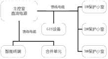
目前直流供电系统,普遍采用三充两电、220V直流母线分段加联络开关的设计模式,直流电经由主控室的直流母线通过馈电屏和分散在各个保护小室的分电屏或连接在直流母线上的直流电源子系统给用电设备供电,这是传统的集中式直流供电系统。作为集中式的直流供电系统,较易发生绝缘降低或大面积的多支路同时接地,更关键的是当处在同一个电气连接的二次回路中出现多点接地时,不同点之前会出现电位差,有短路故障时,可能会引起差动保护误动或保护拒动。At present, the DC power supply system generally adopts the design mode of three chargers and two batteries, 220V DC bus segment and contact switch. The DC power supply subsystem on the bus supplies power to the electrical equipment, which is a traditional centralized DC power supply system. As a centralized DC power supply system, it is more likely to cause insulation degradation or large-area multiple branch circuits to be grounded at the same time. What is more critical is that when multiple points are grounded in the secondary circuit of the same electrical connection, different points will appear before Potential difference, when there is a short-circuit fault, it may cause the differential protection to malfunction or the protection will refuse to operate.
中国专利申请201110130055.0公开了一种当系统内某一部分出现故障时而不至于影响其他设备正常供电的分布式直流电源不间断供电系统。这种分布式直流电源不间断供电系统包括直流母线和若干个分布在不同场合的直流电源子系统,所述若干个直流电源子系统均通过直流母线上构成供电网络。解决了目前站场内庞大的集中式直流电源系统占用了大量的场地空间,也避免了由于直流电源系统的微小故障,影响到所有设备的可靠供电的需求。Chinese patent application 201110130055.0 discloses a distributed DC uninterruptible power supply system that does not affect the normal power supply of other equipment when a certain part of the system fails. This distributed DC power uninterruptible power supply system includes a DC bus and several DC power subsystems distributed in different places, and the several DC power subsystems all form a power supply network through the DC bus. It solves the problem that the huge centralized DC power supply system in the current station takes up a lot of site space, and also avoids the need for reliable power supply of all equipment affected by minor faults in the DC power supply system.
中国专利申请201110130055.0取得一定的技术进步,解决了占用场地空间小、系统出现故障时不间断供电等问题,但仍存在以下问题:Chinese patent application 201110130055.0 has made some technological progress, and solved the problems of small space occupation and uninterrupted power supply when the system fails, but the following problems still exist:
1)系统的网络化供电存在较大的分布电容1) There is a large distributed capacitance in the networked power supply of the system
这种分布式直流不间断供电系统供电网络化的设计方式会增加分布电容。分布电容在线路空载时使线路呈容性,过大会影响支路绝缘检测的精度,造成误报支路接地,并抬高末端的电压,对电力设备绝缘造成危害并影响设备的抗电磁干扰能力。更关键的是分布电容产生的电容电流过大时,二次回路中出现一点接地时,也可能会引起保护设备误动。This distributed DC uninterruptible power supply system power supply network design method will increase the distributed capacitance. Distributed capacitance makes the line capacitive when the line is unloaded. If it is too large, it will affect the accuracy of branch circuit insulation detection, cause false alarms for branch circuit grounding, and increase the voltage at the end, causing damage to the insulation of power equipment and affecting the anti-electromagnetic interference of the equipment. ability. More importantly, when the capacitive current generated by the distributed capacitance is too large, when a point is grounded in the secondary circuit, it may also cause the protection equipment to malfunction.
2)系统间不能实现上下级保护器件的选择性配合(级差配合)2) The selective coordination of the upper and lower protection devices cannot be realized between the systems (gradual coordination)
直流供电系统供电设备多,馈线支路分布广,在系统中有许多支路需要设置断路器或熔断器进行保护,这种分布式直流不间断供电系统通过直流母线将子系统连接在一起,不能实现选择正确保护方案和保护上下级之间的合理配合。导致出现越级跳闸将电力事故扩大化。The DC power supply system has a lot of power supply equipment, and the feeder branches are widely distributed. There are many branches in the system that need to be protected by circuit breakers or fuses. This distributed DC uninterruptible power supply system connects the subsystems together through the DC bus. Realize the reasonable cooperation between choosing the correct protection scheme and protecting the upper and lower levels. Lead to leapfrog tripping to expand the power accident.
3)系统蓄电池运行工况不明朗3) The operating condition of the system battery is unclear
不管是集中式的直流供电系统,还是这种分布式直流不间断供电系统,蓄电池组一直处在浮充备用状态,若其中某些蓄电池出现容量不足或过充等问题,只能通过定期的内阻巡检和核对性充放电来检测,这种检测方式实时性较差,不能第一时间对蓄电池工况做出判断;另外,问题蓄电池进行在线更换维护也比较麻烦,存在一定的安全隐患。Whether it is a centralized DC power supply system or a distributed DC uninterruptible power supply system, the battery packs are always in a floating charge standby state. It is detected by resistance patrol inspection and checking charge and discharge. This detection method has poor real-time performance and cannot judge the working condition of the battery in the first time. In addition, it is more troublesome to replace and maintain the faulty battery online, and there are certain potential safety hazards.
4)系统设计复杂、故障点多4) The system design is complex and there are many failure points
这种分布式直流不间断供电系统设计较为复杂;直流母线多次分段,母线维护或者进行蓄电池组充放电时需要投切多路开关,增加了系统的故障点,且直流母线网络化供电易造成直流母线各段之间互窜,这些问题点一旦出现,不仅对用电设备造成严重损害,而且运行人员较难进行及时排查,更不能进行在线维护。The design of this distributed DC uninterruptible power supply system is relatively complicated; the DC bus is divided into multiple sections, and multiple switches need to be switched on and off when maintaining the bus or charging and discharging the battery pack, which increases the failure points of the system, and the networked DC bus power supply is easy. This will cause the various sections of the DC bus to cross each other. Once these problems appear, not only will it cause serious damage to the electrical equipment, but it will also be difficult for operators to conduct timely investigations, let alone online maintenance.
5)缺乏有效的监控体系5) Lack of an effective monitoring system
中国专利申请201110130055.0是子系统内的通信单元通过RS485或CAN总线或以以太网口与站场内的上位机联网通讯,信息繁琐处理量大,缺乏整体的信息处理和监控。Chinese patent application 201110130055.0 is that the communication unit in the subsystem communicates with the host computer in the station through RS485 or CAN bus or Ethernet port. The information processing volume is cumbersome and lacks overall information processing and monitoring.
发明内容Contents of the invention
本发明的目的是为克服上述现有技术的不足,提供一种分布式直流独立供电系统,将直流供电系统将化整为零,将直流供电系统合理分成几个各自独立运行的直流供电子系统,就近安置在用电设备处。The purpose of the present invention is to overcome the deficiencies of the above-mentioned prior art and provide a distributed DC independent power supply system, which divides the DC power supply system into parts and rationally divides the DC power supply system into several DC power supply subsystems that operate independently , placed near the electrical equipment.
为实现上述目的,本发明采用下述技术方案:To achieve the above object, the present invention adopts the following technical solutions:
一种分布式直流独立供电系统,它包括通信总线以及分别与其连接的总控系统和若干个独立运行的直流供电子系统;每个直流供电子系统均包括若干段直流母线,所述直流母线与馈线终端单元连接,每两段相邻的直流母线通过开关连接,每两段相邻的直流母线配置:A distributed DC independent power supply system, which includes a communication bus, a master control system connected to it, and several independently operated DC power supply subsystems; each DC power supply subsystem includes several sections of DC buses, and the DC buses are connected to the Feeder terminal unit connection, every two adjacent DC busbars are connected through a switch, and every two adjacent DC busbars are configured as follows:
箱式封装的若干个并联的电池组,其输出端分别通过开关连接至直流母线;Several parallel battery packs packaged in a box type, the output ends of which are respectively connected to the DC bus through switches;
至少一个充电单元,用于对各个电池组充电,并热备用给直流母线供电;以及at least one charging unit for charging each battery pack and hot standby for powering the DC bus; and
至少一个监控单元,连接至通信总线,将直流供电子系统的信号测量上送给总控系统并接收总控系统的电网用电信息,设定电网高峰低谷的时间段,将电池组充电时间段控制在用电低谷期,以对电网削峰平谷,控制充电单元对各个电池组交替充电,并控制至少一个电池组与直流母线连通;实时采集电池组的容量、电压、内阻、温度和充电单元的输入输出电压、电流信息,从而判断电池组容量是否满足供电需求。At least one monitoring unit, connected to the communication bus, sends the signal measurement of the DC power supply subsystem to the master control system and receives the grid power consumption information of the master control system, sets the peak and valley time periods of the power grid, and sets the battery pack charging time period Control the low power consumption period to cut the peak and flat valley of the power grid, control the charging unit to alternately charge each battery pack, and control at least one battery pack to connect to the DC bus; collect the capacity, voltage, internal resistance, temperature and charging of the battery pack in real time The input and output voltage and current information of the unit, so as to judge whether the capacity of the battery pack meets the power supply demand.
所述总控系统包括一体化电源监控系统、主站后台系统,两者互相以IEC61850规约通信;所述一体化电源监控系统、主站后台系统均连接至通信总线。The general control system includes an integrated power monitoring system and a master station background system, both of which communicate with each other according to the IEC61850 protocol; the integrated power monitoring system and the master station background system are both connected to the communication bus.
所述直流母线电压为110V;所述电池组、充电单元和监控单元均支持即插即用。The DC bus voltage is 110V; the battery pack, charging unit and monitoring unit all support plug and play.
所述电池组为锂离子电池组或阀控式密封铅酸电池组。The battery pack is a lithium-ion battery pack or a valve-regulated sealed lead-acid battery pack.
优选的,所述电池组为锂离子电池组,采用分布式直流电源电池箱进行箱式封装,具有主动均衡系统,标准接插件支持大电流快速充电。Preferably, the battery pack is a lithium-ion battery pack, which is packaged in a box with a distributed DC power supply battery box, has an active equalization system, and supports high-current fast charging with a standard connector.
所述主动均衡系统包括级联的若干个均衡单元,实现对多节串联锂离子电池的均衡管理,对相邻两节单体电池之间的荷电状态差异进行判断,并把SOC状态高的电池多余传递到SOC较低的单节电池中,实现电池容量最大化,并延长电池组循环寿命。The active equalization system includes several cascaded equalization units to realize the equalization management of multiple lithium-ion batteries connected in series, to judge the state of charge difference between two adjacent single cells, and to control the state of charge of the battery with a high SOC state. The battery surplus is transferred to a single battery with a lower SOC to maximize the battery capacity and extend the cycle life of the battery pack.
所述开关均为可控硅开关器件,在监控单元控制下逐步关断,有效避免分合时产生的冲击电流;所述电池组与直流母线之间还设有具备采样功能的转换投切开关,当监控单元出现故障时,转换投切开关根据本身的采样判断电池组的容量是否还可以继续供电,并实现电池组的一次投切。The switches are thyristor switching devices, which are gradually turned off under the control of the monitoring unit, effectively avoiding the inrush current generated when switching on and off; there is also a switching switch with a sampling function between the battery pack and the DC bus , when the monitoring unit breaks down, the conversion switching switch judges whether the capacity of the battery pack can continue to supply power according to its own sampling, and realizes one-time switching of the battery pack.
所述充电单元的输入端连接至电流进线,输出端通过开关分别连接至直流母线以及各个电池组,所述充电单元为若干个并联连接的充电模块,稳压精度≤±0.5%,稳流精度≤±1.0%,纹波系数≤0.5%;根据现场情况自由投退,输出为DC110V;充电单元平时只是交替给若干组电池组充电,实现在线均衡充电(深度充放电,消除各节电池间的差异)并不直接挂在直流母线上,只有当所有电池组检修维护时,才作为备用充电设备给母线供电;当监控单元出现故障时,能够自主运行。The input end of the charging unit is connected to the current incoming line, and the output end is respectively connected to the DC bus and each battery pack through a switch. The charging unit is several charging modules connected in parallel, and the voltage stabilization accuracy is ≤±0.5%. Accuracy ≤ ± 1.0%, ripple coefficient ≤ 0.5%; free switch on and off according to the site conditions, the output is DC110V; the charging unit usually only charges several groups of battery packs alternately to achieve online balanced charging (deep charge and discharge, eliminating the gap between each battery The difference) is not directly hung on the DC bus, and only when all battery packs are overhauled and maintained, it is used as a backup charging device to supply power to the bus; when the monitoring unit fails, it can run autonomously.
所述电流进线为交流进线、太阳能电池板或风能发电机的输出电,所述交流进线为AC380V或AC220V,所述太阳能电池板或风能发电机的输出电还通过开关连接至直流母线;正常运行时,电池组交替挂在直流母线上给用电设备供电,充电单元脱离母线热备,由监控单元控制充电单元对电池组交替充电。The current incoming line is an AC incoming line, the output power of a solar panel or a wind generator, and the AC incoming line is AC380V or AC220V, and the output power of the solar panel or a wind generator is also connected to a DC bus through a switch ; During normal operation, the battery pack is alternately hung on the DC bus to supply power to the electrical equipment, the charging unit is separated from the bus for hot standby, and the monitoring unit controls the charging unit to alternately charge the battery pack.
监控单元通过荷电状态(SOC)实时监测锂电池的容量,对锂电池充电过程采用恒流模式充电,根据最高单节电池电压调整充电限流值大小,在单节电池电压达到3.65V或电池管理系统(BMS)判定SOC达到100%时,停止充电。The monitoring unit monitors the capacity of the lithium battery in real time through the state of charge (SOC), uses the constant current mode to charge the lithium battery during the charging process, and adjusts the charging current limit value according to the highest single battery voltage. When the single battery voltage reaches 3.65V or the battery When the management system (BMS) judges that the SOC reaches 100%, it stops charging.
本发明的有益效果是:The beneficial effects of the present invention are:
1)将直流供电系统切分后,每个直流子系统独立运行,无线路上的连接,从而使全站的分布电容变小,对系统造成的干扰减弱,二次回路一点接地时,电容放电电流的冲击较弱,很难再引起保护误动。1) After the DC power supply system is divided, each DC subsystem operates independently, and there is no connection on the road, so that the distributed capacitance of the whole station is reduced, and the interference caused to the system is weakened. When the secondary circuit is grounded at one point, the capacitor discharge current The impact is weak, it is difficult to cause protection misoperation.
2)每个直流子系统独立运行,就近供电,电缆长度基本可以确定,且母线、馈线、用电设备明晰,级差配合变得非常简单。2) Each DC subsystem operates independently, supplies power nearby, the cable length can be basically determined, and the busbar, feeder, and electrical equipment are clear, and the level difference coordination becomes very simple.
3)蓄电池组在母线上投退以及充电单元在母线上投退的操作机构采用可控硅开关器件,投退功能模块时有个缓冲、逐步关断的过程,有效避免了分合的冲击电流给母线电压带来波动。3) The operating mechanism for switching on and off the battery pack on the bus and the switching on and off of the charging unit on the bus adopts a thyristor switch device. There is a process of buffering and gradually shutting off when switching on and off the functional module, which effectively avoids the impact current of opening and closing Bring fluctuations to the bus voltage.
锂离子电池组直接作用到母线,不断循环的进行充放电,电池的性能及健康状况通过监控单元的监测实时反映给运行人员,电池隐患可以提早发现提早处理,不再一直处于浮充备用状态,电池状态不明朗。The lithium-ion battery pack directly acts on the busbar, and is continuously charged and discharged. The performance and health of the battery are reflected to the operator in real time through the monitoring of the monitoring unit. The hidden dangers of the battery can be detected and dealt with early, and it is no longer in the floating charge standby state. Battery status is unclear.
锂离子电池目前在电力行业中主要应用于电动汽车、光伏储能等新能源领域;在变电站的应用正处于起步阶段,本发明选择使用了锂离子电池,与阀控式密封铅酸电池相比,优势突出:At present, lithium-ion batteries are mainly used in new energy fields such as electric vehicles and photovoltaic energy storage in the power industry; the application in substations is just in its infancy, and the present invention uses lithium-ion batteries, compared with valve-regulated sealed lead-acid batteries , with outstanding advantages:
①超长寿命,阀控式密封铅酸电池的循环寿命最高只有500次,而锂离子电池循环寿命达到2000次以上。①Extremely long life, the cycle life of the valve-regulated sealed lead-acid battery is only 500 times at most, while the cycle life of the lithium-ion battery reaches more than 2000 times.
②可大电流2C快速充放电,而阀控式密封铅酸电池现在无此性能。②It can charge and discharge quickly with a large current of 2C, but the valve-regulated sealed lead-acid battery does not have this performance now.
③锂离子电池工作温度范围宽广(﹣20℃~﹢75℃)。③Lithium-ion battery has a wide operating temperature range (﹣20℃~﹢75℃).
④锂离子电池体积小,容量大。④Lithium-ion battery is small in size and large in capacity.
⑤锂离子电池可随充随用,无须先放完再充电。⑤ Lithium-ion battery can be charged and used at any time, no need to discharge and recharge first.
⑥绿色环保。锂离子电池不含任何重金属与稀有金属,无毒,无污染,为绝对的绿色环保电池。⑥Environmental protection. Lithium-ion batteries do not contain any heavy metals and rare metals, are non-toxic, non-polluting, and are absolutely green and environmentally friendly batteries.
锂离子电池采用箱式封装技术,标准接口连接到系统。监控单元按照既定的充电策略和控制策略自动控制充电单元交替完成所有电池组的充放电,并24小时实时在线监测所有电池组的容量、电压、内阻、温度等信息和当前的运行状态(BMS),并将这些数据形成月度报表记录供运行人员参考。当有任意一组电池组达不到运行要求时,监控单元通过控制可控硅开关器件实现电池组的投退。Lithium-ion battery adopts box-type packaging technology, and standard interface is connected to the system. The monitoring unit automatically controls the charging unit to alternately complete the charging and discharging of all battery packs according to the established charging strategy and control strategy, and monitors the capacity, voltage, internal resistance, temperature and other information of all battery packs online in 24 hours and the current operating status (BMS ), and form these data into monthly report records for the reference of operating personnel. When any group of battery packs fails to meet the operation requirements, the monitoring unit realizes switching on and off of the battery packs by controlling the thyristor switching device.
直流母线或充电单元在某些特定地区也可引入太阳能、风能充电,使直流供电系统变成一个完全绿色环保无污染的洁净能源系统。The DC bus or charging unit can also be charged with solar energy and wind energy in some specific areas, making the DC power supply system a completely green, environmentally friendly and pollution-free clean energy system.
4)分布式直流独立供电系统,消除了各个用电设备间直流母线的关联,有效的规避了直流母线互窜的问题。直流子系统到用电设备间电缆长度变短,导线截面积对输电信号的衰减可忽略,直流母线可直接降压到110V,带动全站的低压微型断路器电压等级下调,提高经济性。4) Distributed DC independent power supply system eliminates the connection of DC bus between various electrical equipment, effectively avoiding the problem of DC bus crossing. The length of the cable between the DC subsystem and the electrical equipment is shortened, the attenuation of the transmission signal by the cross-sectional area of the conductor is negligible, and the DC bus can be directly reduced to 110V, which drives the voltage level of the low-voltage miniature circuit breakers in the whole station to be lowered, improving economy.
电池组、充电单元和监控单元均支持即插即用,三者采用模块化设计,充电单元作为一个功能模块、监控单元作为一个功能模块,电池组采用箱式封装后也作为一个功能模块,直流子系统的搭建就是一个模块组装的过程,每个功能模块对外均采用统一标准的电气及物理接口,均支持即插即用,任一功能模块出现故障后,备件均方便替换;减小故障对系统运行带来的影响,替换下来的故障模块可进行离线式维修。The battery pack, charging unit and monitoring unit all support plug and play. The three adopt a modular design. The charging unit serves as a functional module, and the monitoring unit serves as a functional module. The battery pack is also used as a functional module after being packaged in a box. The construction of the subsystem is a process of module assembly. Each functional module adopts a unified electrical and physical interface to the outside world, and supports plug-and-play. After any functional module fails, spare parts can be easily replaced; The impact brought by the operation of the system, the replaced faulty module can be repaired offline.
5)系统中监控单元对充电单元和具备主动均衡系统的电池箱等模块的监测和控制策略自动完成,无需人工干预,出现问题后系统会及时报警通知运行人员处理,完全适用于无人值守变电站。监控单元可通过SOC实时监测锂离子电池的容量,对锂电池充电过程采用恒流模式充电,根据最高单节电池电压调整充电限流值大小,在单节电池电压达到3.65V或BMS判定SOC达到100%时,停止充电。监控单元对上支持多种规约通讯,具备通过实时检测系统内的各种信息对直流子系统进行智能分析,隐患预判等高级应用,并将分析结果形成月度报表提交用户,协助用户实现系统的管理。5) The monitoring and control strategy of the monitoring unit in the system for the charging unit and the battery box with active balancing system and other modules is automatically completed without manual intervention. When a problem occurs, the system will promptly notify the operator to deal with it. It is completely suitable for unattended substations . The monitoring unit can monitor the capacity of the lithium-ion battery in real time through the SOC. The charging process of the lithium-ion battery is charged in a constant current mode. The charging current limit value is adjusted according to the highest single-cell battery voltage. 100%, stop charging. The monitoring unit supports a variety of protocols for communication, and has advanced applications such as intelligent analysis of the DC subsystem through real-time detection of various information in the system, hidden danger prediction, etc., and submits the analysis results to the user in a monthly report to assist the user in realizing the system. manage.
监控单元根据总控系统得来的电网运行工况数据进行智能分析,判断出电网用电的高峰期和低谷期,在对电池充电时间段的选择上采取控制,或者通过人工判断手动设定高峰低谷的时间段,避免在用电高峰期对电池充电,将电池充电时间段控制在用电低谷期,对电网起到削峰平谷的作用。The monitoring unit conducts intelligent analysis based on the grid operating condition data obtained from the master control system, and judges the peak and valley periods of grid power consumption, and controls the selection of the battery charging time period, or manually sets the peak value through manual judgment. Avoid charging the battery during the peak period of electricity consumption, and control the charging period of the battery in the period of low electricity consumption, so as to cut the peak and flatten the power grid.
总控系统及独立运行的直流供电子系统均连接至通信总线,信息交换方便快捷,能够整体有效地控制所有子系统的正常运行。Both the master control system and the independently operating DC power supply subsystem are connected to the communication bus, so that the information exchange is convenient and fast, and the normal operation of all subsystems can be effectively controlled as a whole.
附图说明Description of drawings
图1是传统直流供电系统的结构示意图;Figure 1 is a schematic structural diagram of a traditional DC power supply system;
图2是本发明的分布式直流供电系统的结构示意图;Fig. 2 is a schematic structural view of the distributed DC power supply system of the present invention;
图3是本发明的通讯架构图;Fig. 3 is a communication architecture diagram of the present invention;
图4是实施例1直流子系统结构示意图;Fig. 4 is a schematic structural diagram of the DC subsystem of
图5是实施例2直流子系统结构示意图;Fig. 5 is a schematic structural diagram of the DC subsystem of
图6是实施例3直流子系统结构示意图;Fig. 6 is a schematic structural diagram of the DC subsystem of Embodiment 3;
图7是实施例4直流子系统结构示意图;Fig. 7 is a schematic structural diagram of the DC subsystem of Embodiment 4;
图8是实施例5直流子系统结构示意图;Fig. 8 is a schematic structural diagram of the DC subsystem of Embodiment 5;
图9是实施例6直流子系统结构示意图;Fig. 9 is a schematic structural diagram of the DC subsystem of Embodiment 6;
图10是实施例7直流子系统结构示意图;Fig. 10 is a schematic structural diagram of the DC subsystem of
图11是实施例8直流子系统结构示意图;Fig. 11 is a schematic structural diagram of the DC subsystem of Embodiment 8;
图12是实施例9直流子系统结构示意图;Fig. 12 is a schematic structural diagram of the DC subsystem of Embodiment 9;
图13是主动均衡系统的电路图。Figure 13 is a circuit diagram of an active equalization system.
具体实施方式Detailed ways
下面结合附图和实施例对本发明进行进一步的阐述,应该说明的是,下述说明仅是为了解释本发明,并不对其内容进行限定。The present invention will be further described below in conjunction with the accompanying drawings and embodiments. It should be noted that the following description is only for explaining the present invention and not limiting its content.
本发明适用于发电站、变电站、换流站等所有需要直流供电的系统。The invention is applicable to all systems requiring DC power supply such as power stations, substations and converter stations.
一种分布式直流独立供电系统,它包括通信总线以及分别与其连接的总控系统和若干个独立运行的直流供电子系统;每个直流供电子系统均包括若干段直流母线,所述直流母线与馈线终端单元连接,每两段相邻的直流母线通过开关连接,每两段相邻的直流母线配置:A distributed DC independent power supply system, which includes a communication bus, a master control system connected to it, and several independently operated DC power supply subsystems; each DC power supply subsystem includes several sections of DC buses, and the DC buses are connected to the Feeder terminal unit connection, every two adjacent DC busbars are connected through a switch, and every two adjacent DC busbars are configured as follows:
箱式封装的若干个并联的电池组,其输出端分别通过开关连接至直流母线;Several parallel battery packs packaged in a box type, the output ends of which are respectively connected to the DC bus through switches;
至少一个充电单元,用于对各个电池组充电,并热备用给直流母线供电;以及at least one charging unit for charging each battery pack and hot standby for powering the DC bus; and
至少一个监控单元,连接至通信总线,将直流供电子系统的信号测量上送给总控系统并接收总控系统的电网用电信息,设定电网高峰低谷的时间段,将电池组充电时间段控制在用电低谷期,以对电网削峰平谷,控制充电单元对各个电池组交替充电,并控制至少一个电池组与直流母线连通;实时采集电池组的容量、电压、内阻、温度和充电单元的输入输出电压、电流信息,从而判断电池组容量是否满足供电需求。At least one monitoring unit, connected to the communication bus, sends the signal measurement of the DC power supply subsystem to the master control system and receives the grid power consumption information of the master control system, sets the peak and valley time periods of the power grid, and sets the battery pack charging time period Control the low power consumption period to cut the peak and flat valley of the power grid, control the charging unit to alternately charge each battery pack, and control at least one battery pack to connect to the DC bus; collect the capacity, voltage, internal resistance, temperature and charging of the battery pack in real time The input and output voltage and current information of the unit, so as to judge whether the capacity of the battery pack meets the power supply demand.
所述总控系统包括一体化电源监控系统、主站后台系统,两者互相以IEC61850规约通信;所述一体化电源监控系统、主站后台系统均连接至通信总线。The general control system includes an integrated power monitoring system and a master station background system, both of which communicate with each other according to the IEC61850 protocol; the integrated power monitoring system and the master station background system are both connected to the communication bus.
所述直流母线电压为110V;所述电池组、充电单元和监控单元均支持即插即用。The DC bus voltage is 110V; the battery pack, charging unit and monitoring unit all support plug and play.
所述电池组为锂离子电池组或阀控式密封铅酸电池组。The battery pack is a lithium-ion battery pack or a valve-regulated sealed lead-acid battery pack.
优选的,所述电池组为锂离子电池组,采用分布式直流电源电池箱进行箱式封装,具有主动均衡系统,标准接插件支持大电流快速充电。Preferably, the battery pack is a lithium-ion battery pack, which is packaged in a box with a distributed DC power supply battery box, has an active equalization system, and supports high-current fast charging with a standard connector.
所述主动均衡系统包括级联的若干个均衡单元,实现对多节串联锂离子电池的均衡管理,对相邻两节单体电池之间的荷电状态差异进行判断,并把SOC状态高的电池多余传递到SOC较低的单节电池中,实现电池容量最大化,并延长电池组循环寿命。The active equalization system includes several cascaded equalization units to realize the equalization management of multiple lithium-ion batteries connected in series, to judge the state of charge difference between two adjacent single cells, and to control the state of charge of the battery with a high SOC state. The battery surplus is transferred to a single battery with a lower SOC to maximize the battery capacity and extend the cycle life of the battery pack.
所述开关均为可控硅开关器件,在监控单元控制下逐步关断,有效避免分合时产生的冲击电流;所述电池组与直流母线之间还设有具备采样功能的转换投切开关,当监控单元出现故障时,转换投切开关根据本身的采样判断电池组的容量是否还可以继续供电,并实现电池组的一次投切。The switches are thyristor switching devices, which are gradually turned off under the control of the monitoring unit, effectively avoiding the inrush current generated when switching on and off; there is also a switching switch with a sampling function between the battery pack and the DC bus , when the monitoring unit breaks down, the conversion switching switch judges whether the capacity of the battery pack can continue to supply power according to its own sampling, and realizes one-time switching of the battery pack.
所述充电单元的输入端连接至电流进线,输出端通过开关分别连接至直流母线以及各个电池组,所述充电单元为若干个并联连接的充电模块,稳压精度≤±0.5%,稳流精度≤±1.0%,纹波系数≤0.5%;根据现场情况自由投退,输出为DC110V;充电单元平时只是交替给若干组电池组充电,实现在线均衡充电(深度充放电,消除各节电池间的差异)并不直接挂在直流母线上,只有当所有电池组检修维护时,才作为备用充电设备给母线供电;当监控单元出现故障时,能够自主运行。The input end of the charging unit is connected to the current incoming line, and the output end is respectively connected to the DC bus and each battery pack through a switch. The charging unit is several charging modules connected in parallel, and the voltage stabilization accuracy is ≤±0.5%. Accuracy ≤ ± 1.0%, ripple coefficient ≤ 0.5%; free switch on and off according to the site conditions, the output is DC110V; the charging unit usually only charges several groups of battery packs alternately to achieve online balanced charging (deep charge and discharge, eliminating the gap between each battery The difference) is not directly hung on the DC bus, and only when all battery packs are overhauled and maintained, it is used as a backup charging device to supply power to the bus; when the monitoring unit fails, it can run autonomously.
所述电流进线为交流进线、太阳能电池板或风能发电机的输出电,所述交流进线为AC380V或AC220V,所述太阳能电池板或风能发电机的输出电还通过开关连接至直流母线;正常运行时,电池组交替挂在直流母线上给用电设备供电,充电单元脱离母线热备,由监控单元控制充电单元对电池组交替充电。The current incoming line is an AC incoming line, the output power of a solar panel or a wind generator, and the AC incoming line is AC380V or AC220V, and the output power of the solar panel or a wind generator is also connected to a DC bus through a switch ; During normal operation, the battery pack is alternately hung on the DC bus to supply power to the electrical equipment, the charging unit is separated from the bus for hot standby, and the monitoring unit controls the charging unit to alternately charge the battery pack.
监控单元通过荷电状态(SOC)实时监测锂电池的容量,对锂电池充电过程采用恒流模式充电,根据最高单节电池电压调整充电限流值大小,在单节电池电压达到3.65V或电池管理系统(BMS)判定SOC达到100%时,停止充电。The monitoring unit monitors the capacity of the lithium battery in real time through the state of charge (SOC), uses the constant current mode to charge the lithium battery during the charging process, and adjusts the charging current limit value according to the highest single battery voltage. When the single battery voltage reaches 3.65V or the battery When the management system (BMS) judges that the SOC reaches 100%, it stops charging.
以下是每个直流子系统的具体实施案例:The following are specific implementation examples for each DC subsystem:
实施例1Example 1
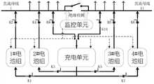
如图4所示的直流子系统包括一段直流母线,直流母线与馈线终端单元连接,该直流母线配置:并联的1#电池组和2#电池组、一充电单元以及一监控单元。The DC subsystem shown in Figure 4 includes a section of DC bus, which is connected to the feeder terminal unit. The DC bus is configured with: 1# battery pack and 2# battery pack connected in parallel, a charging unit and a monitoring unit.
当1#电池组供电,2#电池组充电时,开关K1、开关K4断开,开关K2、开关K3闭合;2#电池组充电完毕时开关K3断开,2#电池组处于热备状态。当1#电池组电量不足时,系统自动转为由2#电池组供电1#电池组充电,此时,开关K1、开关K4闭合,然后开关K2断开,充电单元对1#电池组充电,充电完毕开关K1断开,1#电池组处于热备状态。When the 1# battery pack supplies power and the 2# battery pack is charging, the switch K1 and switch K4 are turned off, and the switch K2 and switch K3 are closed; when the 2# battery pack is fully charged, the switch K3 is turned off, and the 2# battery pack is in the standby state. When the power of the 1# battery pack is insufficient, the system automatically switches to the 1# battery pack powered by the 2# battery pack for charging. At this time, the switch K1 and switch K4 are closed, and then the switch K2 is turned off, and the charging unit charges the 1# battery pack. After charging, the switch K1 is turned off, and the 1# battery pack is in hot standby state.
若充电单元出现异常,开关K3、开关K4同时闭合,两组电池组同时给直流母线供电,供电时间延长一倍。If the charging unit is abnormal, the switch K3 and the switch K4 are closed at the same time, and the two battery packs supply power to the DC bus at the same time, and the power supply time is doubled.
若电池组出现异常,开关K5闭合,由充电单元给母线供电。充电单元和电池组任何一个出现异常,监控单元同时会有报警通知后台和调度中心,安排人员及时处理。If the battery pack is abnormal, the switch K5 is closed, and the charging unit supplies power to the bus. If any abnormality occurs in the charging unit or the battery pack, the monitoring unit will send an alarm to notify the background and dispatching center at the same time, and arrange personnel to deal with it in time.
开关K1~K5均为可控硅开关器件,在监控单元控制下可逐步关断,可以有效避免分合时产生的冲击电流。The switches K1-K5 are thyristor switching devices, which can be turned off gradually under the control of the monitoring unit, which can effectively avoid the inrush current generated when opening and closing.
充电单元平时只是交替给两组电池充电,实现在线均衡充电(深度充放电,消除各节电池间的差异)并不直接挂在母线上,除非当两组电池检修维护时,开关K7才会闭合,充电单元作为备用充电设备给直流母线供电。The charging unit usually only charges the two sets of batteries alternately to achieve online balanced charging (deep charge and discharge, eliminating the differences between the batteries) and is not directly connected to the busbar, unless the switch K7 is closed when the two sets of batteries are overhauled and maintained , the charging unit serves as a backup charging device to supply power to the DC bus.
电流进线为交流进线。The current incoming line is an AC incoming line.
电池组采用锂电池,支持大电流快速充电。充电单元采用AC/DC充电模块。The battery pack uses a lithium battery that supports high-current fast charging. The charging unit adopts AC/DC charging module.
实施例2Example 2
如图5所示的直流子系统与实施例1相比唯一的不同是:每组蓄电池通过两组可控硅开关器件连接到母线上,互为备用,增加母线的可靠性。The only difference between the DC subsystem shown in Figure 5 and
实施例3Example 3
如图6所示的直流子系统与实施例1相比唯一的不同是:系统多增加了3#电池组和4#电池组这两组蓄电池,正常运行时两组蓄电池同时挂在母线上进行供电,2×2的方式进行交替投入,充电单元对分别对脱离的2组蓄电池依次进行充电,增加电池组的可靠性。The only difference between the DC subsystem shown in Figure 6 and
实施例4Example 4
如图7所示的直流子系统与实施例1相比唯一的不同是:引入了太阳能、风能等新的洁净能源,一方面,在太阳能、风能资源充足的情况下,直接通过直流母线给设备供电,开关K6接通,充电单元和电池组都处在热备状态,在太阳能、风能资源不足的情况下投入电池组。The only difference between the DC subsystem shown in Figure 7 and
另一方面,充电单元可直接从电网上取交流电转换成直流电给电池组充电,也可以直接引入太阳能、风能并转换成稳定的直流给电池组充电。On the other hand, the charging unit can directly take alternating current from the grid and convert it into direct current to charge the battery pack, or directly introduce solar energy and wind energy and convert it into stable direct current to charge the battery pack.
实施例5Example 5
如图8所示的直流子系统与实施例1相比唯一的不同是:两组电池组到直流母线之间增加了转换投切开关,转换投切开关具备采样功能,当监控单元出现故障时,转换投切开关可以根据本身的采样判断电池组的容量是否还可以继续供电,并进行电池组的一次投切。The only difference between the DC sub-system shown in Figure 8 and
实施例6Example 6
如图9所示的直流子系统包括两段直流母线,直流母线与馈线终端单元连接,两段直流母线通过联络开关连接,每段直流母线配置与实施例1相同,只是两段母线四组蓄电池共用一套充电单元和监控单元。监控单元同时检测蓄电池组的运行工况,充电单元依次给四组电池组充电。The DC subsystem shown in Figure 9 includes two sections of DC bus, the DC bus is connected to the feeder terminal unit, and the two sections of DC bus are connected through a tie switch. The configuration of each section of DC bus is the same as that of
实施例7Example 7
如图10所示的直流子系统与实施例6相比唯一的不同是:每段母线带各自的充电单元,两段母线仍然共用一套监控单元。The only difference between the DC subsystem shown in Figure 10 and Embodiment 6 is that each bus section has its own charging unit, and the two bus sections still share a monitoring unit.
实施例8Example 8
如图11所示的直流子系统包括一段直流母线,直流母线与馈线终端单元连接,该直流母线配置:一铅酸蓄电池电池组,一充电单元,以及至少一监控单元;充电单元输入端为交流进线。The DC subsystem shown in Figure 11 includes a section of DC bus, which is connected to the feeder terminal unit. The DC bus is configured with: a lead-acid battery pack, a charging unit, and at least one monitoring unit; the input of the charging unit is AC incoming line.
正常运行时,充电单元经直流母线对蓄电池充电,同时提供经常负荷电流,蓄电池处于浮充备用状态。During normal operation, the charging unit charges the battery through the DC bus, and at the same time provides a constant load current, and the battery is in a floating charge standby state.
实施例9Example 9
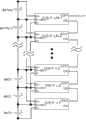
如图12所示的直流子系统包括一段直流母线,直流母线与馈线终端单元连接,该直流母线配置:一监控单元,若干个铅酸蓄电池电池组以及与每个铅酸蓄电池组配合的充电单元,充电单元输入端为交流进线。The DC subsystem shown in Figure 12 includes a section of DC bus, which is connected to the feeder terminal unit. The DC bus is configured with: a monitoring unit, several lead-acid battery packs and a charging unit matched with each lead-acid battery pack , The input terminal of the charging unit is an AC incoming line.
单节12V用专用充电单元充电,用升压装置升压到110V,并联到母线上使用。正常运行时,充电单元的输出直接通过升压装置输出到母线给设备供电,电池处于浮充备用状态。Single-cell 12V is charged with a dedicated charging unit, boosted to 110V with a booster, and connected to the bus in parallel for use. During normal operation, the output of the charging unit is directly output to the bus through the booster device to supply power to the equipment, and the battery is in a floating charge standby state.
实施例1~9可根据实际设计需要自由组合,以满足更复杂的系统要求。
上述虽然结合附图对本发明的具体实施方式进行了描述,但并非对本发明保护范围的限制,在本发明的技术方案的基础上,本领域技术人员不需要付出创造性劳动即可做出的各种修改或变形仍在本发明的保护范围以内。Although the specific implementation of the present invention has been described above in conjunction with the accompanying drawings, it does not limit the protection scope of the present invention. On the basis of the technical solution of the present invention, those skilled in the art can make various Modifications or variations are still within the protection scope of the present invention.
Claims (9)
Priority Applications (1)
| Application Number | Priority Date | Filing Date | Title |
|---|---|---|---|
| CN201310082865.2ACN103117595B (en) | 2013-03-15 | 2013-03-15 | Distributed direct current independent power supply system |
Applications Claiming Priority (1)
| Application Number | Priority Date | Filing Date | Title |
|---|---|---|---|
| CN201310082865.2ACN103117595B (en) | 2013-03-15 | 2013-03-15 | Distributed direct current independent power supply system |
Publications (2)
| Publication Number | Publication Date |
|---|---|
| CN103117595Atrue CN103117595A (en) | 2013-05-22 |
| CN103117595B CN103117595B (en) | 2015-02-04 |
Family
ID=48415897
Family Applications (1)
| Application Number | Title | Priority Date | Filing Date |
|---|---|---|---|
| CN201310082865.2AActiveCN103117595B (en) | 2013-03-15 | 2013-03-15 | Distributed direct current independent power supply system |
Country Status (1)
| Country | Link |
|---|---|
| CN (1) | CN103117595B (en) |
Cited By (8)
| Publication number | Priority date | Publication date | Assignee | Title |
|---|---|---|---|---|
| CN104701935A (en)* | 2015-02-12 | 2015-06-10 | 上海卫星装备研究所 | High-reliability mobile DC power source |
| CN107632269A (en)* | 2017-09-21 | 2018-01-26 | 孙亮 | The online charging-discharge tester system of communication storage battery |
| CN108539840A (en)* | 2018-05-04 | 2018-09-14 | 香江科技股份有限公司 | A kind of distributed DC battery power supply system |
| CN109435773A (en)* | 2017-08-31 | 2019-03-08 | 比亚迪股份有限公司 | Battery equalization method, system, vehicle, storage medium and electronic equipment |
| CN110676833A (en)* | 2018-07-02 | 2020-01-10 | 比亚迪股份有限公司 | Track energy feedback system and control method thereof |
| CN111525683A (en)* | 2020-04-29 | 2020-08-11 | 广东电科院能源技术有限责任公司 | Transformer substation direct-current battery device and transformer substation direct-current battery system |
| CN113777504A (en)* | 2021-08-31 | 2021-12-10 | 云南电网有限责任公司保山供电局 | Storage battery pack capacity checking system |
| CN114374266A (en)* | 2022-01-25 | 2022-04-19 | 中国铁建高新装备股份有限公司 | A construction vehicle power supply system, construction vehicle and power supply control method |
Citations (6)
| Publication number | Priority date | Publication date | Assignee | Title |
|---|---|---|---|---|
| US20090086520A1 (en)* | 2006-04-18 | 2009-04-02 | Kazuhito Nishimura | Grid-Connected Power Conditioner and Grid-Connected Power Supply System |
| CN201576956U (en)* | 2009-10-30 | 2010-09-08 | 河南红宇特种汽车有限公司 | Emergency DC power supply vehicle |
| CN102231613A (en)* | 2011-06-29 | 2011-11-02 | 湖南大学 | Distributed photovoltaic generating and building cold and heat source coupling system |
| CN102290841A (en)* | 2011-08-13 | 2011-12-21 | 罗俊亚 | Peak clipping and valley filling electric vehicle swapping station for distribution network |
| CN102832653A (en)* | 2011-12-29 | 2012-12-19 | 中航锂电(洛阳)有限公司 | Active equalization circuit for multi-monomer series battery |
| CN203119615U (en)* | 2013-03-15 | 2013-08-07 | 山东鲁能智能技术有限公司 | Distributed direct-current independent power supply system |
- 2013
- 2013-03-15CNCN201310082865.2Apatent/CN103117595B/enactiveActive
Patent Citations (6)
| Publication number | Priority date | Publication date | Assignee | Title |
|---|---|---|---|---|
| US20090086520A1 (en)* | 2006-04-18 | 2009-04-02 | Kazuhito Nishimura | Grid-Connected Power Conditioner and Grid-Connected Power Supply System |
| CN201576956U (en)* | 2009-10-30 | 2010-09-08 | 河南红宇特种汽车有限公司 | Emergency DC power supply vehicle |
| CN102231613A (en)* | 2011-06-29 | 2011-11-02 | 湖南大学 | Distributed photovoltaic generating and building cold and heat source coupling system |
| CN102290841A (en)* | 2011-08-13 | 2011-12-21 | 罗俊亚 | Peak clipping and valley filling electric vehicle swapping station for distribution network |
| CN102832653A (en)* | 2011-12-29 | 2012-12-19 | 中航锂电(洛阳)有限公司 | Active equalization circuit for multi-monomer series battery |
| CN203119615U (en)* | 2013-03-15 | 2013-08-07 | 山东鲁能智能技术有限公司 | Distributed direct-current independent power supply system |
Cited By (9)
| Publication number | Priority date | Publication date | Assignee | Title |
|---|---|---|---|---|
| CN104701935A (en)* | 2015-02-12 | 2015-06-10 | 上海卫星装备研究所 | High-reliability mobile DC power source |
| CN109435773A (en)* | 2017-08-31 | 2019-03-08 | 比亚迪股份有限公司 | Battery equalization method, system, vehicle, storage medium and electronic equipment |
| CN109435773B (en)* | 2017-08-31 | 2022-02-08 | 比亚迪股份有限公司 | Cell balancing method, system, vehicle, storage medium and electronic device |
| CN107632269A (en)* | 2017-09-21 | 2018-01-26 | 孙亮 | The online charging-discharge tester system of communication storage battery |
| CN108539840A (en)* | 2018-05-04 | 2018-09-14 | 香江科技股份有限公司 | A kind of distributed DC battery power supply system |
| CN110676833A (en)* | 2018-07-02 | 2020-01-10 | 比亚迪股份有限公司 | Track energy feedback system and control method thereof |
| CN111525683A (en)* | 2020-04-29 | 2020-08-11 | 广东电科院能源技术有限责任公司 | Transformer substation direct-current battery device and transformer substation direct-current battery system |
| CN113777504A (en)* | 2021-08-31 | 2021-12-10 | 云南电网有限责任公司保山供电局 | Storage battery pack capacity checking system |
| CN114374266A (en)* | 2022-01-25 | 2022-04-19 | 中国铁建高新装备股份有限公司 | A construction vehicle power supply system, construction vehicle and power supply control method |
Also Published As
| Publication number | Publication date |
|---|---|
| CN103117595B (en) | 2015-02-04 |
Similar Documents
| Publication | Publication Date | Title |
|---|---|---|
| CN103117595B (en) | Distributed direct current independent power supply system | |
| CN103606943B (en) | A kind of microgrid Ni-MH battery energy storage system | |
| CN102270878B (en) | Direct current power supply system for transformer substation and control method thereof | |
| CN202721495U (en) | AC and DC integrated uninterruptible power supply | |
| CN103219766B (en) | Non-floating charge lithium electricity type station DC power system | |
| CN201893567U (en) | Electric energy supply system for electric automobile | |
| CN203119615U (en) | Distributed direct-current independent power supply system | |
| CN112186822A (en) | Energy storage system based on low-voltage isolation battery unit | |
| CN203326621U (en) | Non floating charge lithium battery type DC (direct current) power system used for station | |
| CN103117596B (en) | Distributed direct-current power supply system for substation | |
| CN204425037U (en) | A kind of maintenance-free high frequence Switching Power Supply DC power cabinet | |
| CN208955660U (en) | Photovoltaic AC/DC system of transformer substation | |
| CN214375177U (en) | Remote battery pack capacity checking device for dual-power direct-current system | |
| CN202616809U (en) | Battery module, battery system and direct current screen power supply system | |
| CN207719884U (en) | A kind of movable type AC/DC integrated Power supply alteration load transfer device | |
| CN204425022U (en) | A kind of intelligent communication power-supply system | |
| CN117578539A (en) | Energy storage system | |
| CN117748668A (en) | Energy transfer system and method between battery PACKs of energy storage system | |
| CN203119617U (en) | Distributed direct-current independent power supply system for transformer substation | |
| CN203119616U (en) | Distributed direct-current power supply subsystem of intelligent substation | |
| CN114498893B (en) | 10KV dual-power supply automatic switching and intelligent energy management system | |
| CN205583821U (en) | Mobile modular emergency repair AC and DC integrated power supply | |
| CN115833346A (en) | Redundant direct-current power supply storage battery pack capable of achieving online impact and working method thereof | |
| CN115589060A (en) | Standby device of direct current system for station | |
| CN211930271U (en) | An intelligent energy storage device for distribution transformer capacity increase |
Legal Events
| Date | Code | Title | Description |
|---|---|---|---|
| C06 | Publication | ||
| PB01 | Publication | ||
| C10 | Entry into substantive examination | ||
| SE01 | Entry into force of request for substantive examination | ||
| C14 | Grant of patent or utility model | ||
| GR01 | Patent grant | ||
| CP03 | Change of name, title or address | Address after:250101 Electric Power Intelligent Robot Production Project 101 in Jinan City, Shandong Province, South of Feiyue Avenue and East of No. 26 Road (ICT Industrial Park) Patentee after:National Network Intelligent Technology Co., Ltd. Address before:250101 Qilu Software Park building, Ji'nan hi tech Zone, Shandong, B-205 Patentee before:Shandong Luneng Intelligent Technology Co., Ltd. | |
| CP03 | Change of name, title or address | ||
| TR01 | Transfer of patent right | Effective date of registration:20201214 Address after:Room 902, 9 / F, block B, Yinhe building, 2008 Xinluo street, hi tech Zone, Jinan City, Shandong Province Patentee after:Shandong Luneng Software Technology Co.,Ltd. intelligent electrical branch Address before:250101 power intelligent robot production project 101 south of Feiyue Avenue and east of No.26 Road (in ICT Industrial Park) in Suncun District of Gaoxin, Jinan City, Shandong Province Patentee before:National Network Intelligent Technology Co.,Ltd. | |
| TR01 | Transfer of patent right | ||
| CP01 | Change in the name or title of a patent holder | Address after:Room 902, 9 / F, block B, Yinhe building, 2008 Xinluo street, hi tech Zone, Jinan City, Shandong Province Patentee after:Shandong luruan Digital Technology Co.,Ltd. smart energy branch Address before:Room 902, 9 / F, block B, Yinhe building, 2008 Xinluo street, hi tech Zone, Jinan City, Shandong Province Patentee before:Shandong Luneng Software Technology Co.,Ltd. intelligent electrical branch | |
| CP01 | Change in the name or title of a patent holder |