CN103110437A - Exposure device for spinal column posterior minimally invasive nail placing operation - Google Patents
Exposure device for spinal column posterior minimally invasive nail placing operationDownload PDFInfo
- Publication number
- CN103110437A CN103110437ACN2013100354001ACN201310035400ACN103110437ACN 103110437 ACN103110437 ACN 103110437ACN 2013100354001 ACN2013100354001 ACN 2013100354001ACN 201310035400 ACN201310035400 ACN 201310035400ACN 103110437 ACN103110437 ACN 103110437A
- Authority
- CN
- China
- Prior art keywords
- handle
- retractor
- minimally invasive
- exposure device
- hook body
- Prior art date
- Legal status (The legal status is an assumption and is not a legal conclusion. Google has not performed a legal analysis and makes no representation as to the accuracy of the status listed.)
- Granted
Links
- 238000000034methodMethods0.000claimsabstractdescription32
- 238000003780insertionMethods0.000claimsabstractdescription15
- 230000037431insertionEffects0.000claimsabstractdescription15
- 238000001356surgical procedureMethods0.000claimsabstractdescription13
- 210000002517zygapophyseal jointAnatomy0.000claimsabstractdescription13
- 239000002184metalSubstances0.000claimsdescription6
- 241000251468ActinopterygiiSpecies0.000claimsdescription4
- 230000002980postoperative effectEffects0.000claimsdescription4
- 238000005452bendingMethods0.000claimsdescription3
- 210000003205muscleAnatomy0.000abstractdescription15
- 230000006378damageEffects0.000abstractdescription10
- 210000004872soft tissueAnatomy0.000abstractdescription4
- 210000000988bone and boneAnatomy0.000abstractdescription2
- 238000000926separation methodMethods0.000abstract1
- 230000000451tissue damageEffects0.000abstract1
- 231100000827tissue damageToxicity0.000abstract1
- 210000001519tissueAnatomy0.000description5
- 230000000740bleeding effectEffects0.000description3
- 238000010586diagramMethods0.000description3
- 238000005516engineering processMethods0.000description3
- 208000014674injuryDiseases0.000description3
- 238000011084recoveryMethods0.000description3
- 230000008733traumaEffects0.000description3
- 208000008035Back PainDiseases0.000description2
- 208000008930Low Back PainDiseases0.000description2
- 208000029549Muscle injuryDiseases0.000description2
- 208000002847Surgical WoundDiseases0.000description2
- 230000009286beneficial effectEffects0.000description2
- 208000032170Congenital AbnormalitiesDiseases0.000description1
- 206010027452Metastases to boneDiseases0.000description1
- 206010028289Muscle atrophyDiseases0.000description1
- 208000007103SpondylolisthesisDiseases0.000description1
- 210000003484anatomyAnatomy0.000description1
- 230000006835compressionEffects0.000description1
- 238000007906compressionMethods0.000description1
- 230000007850degenerationEffects0.000description1
- 238000002059diagnostic imagingMethods0.000description1
- 238000002513implantationMethods0.000description1
- 210000003041ligamentAnatomy0.000description1
- 230000007774longtermEffects0.000description1
- 210000004705lumbosacral regionAnatomy0.000description1
- 238000002324minimally invasive surgeryMethods0.000description1
- 230000020763muscle atrophyEffects0.000description1
- 201000000585muscular atrophyDiseases0.000description1
- 238000007788rougheningMethods0.000description1
- 210000000278spinal cordAnatomy0.000description1
- 206010041569spinal fractureDiseases0.000description1
- 208000005198spinal stenosisDiseases0.000description1
- 230000001225therapeutic effectEffects0.000description1
Images


Classifications
- A—HUMAN NECESSITIES
- A61—MEDICAL OR VETERINARY SCIENCE; HYGIENE
- A61B—DIAGNOSIS; SURGERY; IDENTIFICATION
- A61B17/00—Surgical instruments, devices or methods
- A61B17/02—Surgical instruments, devices or methods for holding wounds open, e.g. retractors; Tractors
- A61B17/0218—Surgical instruments, devices or methods for holding wounds open, e.g. retractors; Tractors for minimally invasive surgery
- A—HUMAN NECESSITIES
- A61—MEDICAL OR VETERINARY SCIENCE; HYGIENE
- A61B—DIAGNOSIS; SURGERY; IDENTIFICATION
- A61B17/00—Surgical instruments, devices or methods
- A61B17/02—Surgical instruments, devices or methods for holding wounds open, e.g. retractors; Tractors
- A—HUMAN NECESSITIES
- A61—MEDICAL OR VETERINARY SCIENCE; HYGIENE
- A61B—DIAGNOSIS; SURGERY; IDENTIFICATION
- A61B17/00—Surgical instruments, devices or methods
- A61B17/02—Surgical instruments, devices or methods for holding wounds open, e.g. retractors; Tractors
- A61B17/025—Joint distractors
- A—HUMAN NECESSITIES
- A61—MEDICAL OR VETERINARY SCIENCE; HYGIENE
- A61B—DIAGNOSIS; SURGERY; IDENTIFICATION
- A61B17/00—Surgical instruments, devices or methods
- A61B17/02—Surgical instruments, devices or methods for holding wounds open, e.g. retractors; Tractors
- A61B17/025—Joint distractors
- A61B2017/0256—Joint distractors for the spine
- A—HUMAN NECESSITIES
- A61—MEDICAL OR VETERINARY SCIENCE; HYGIENE
- A61B—DIAGNOSIS; SURGERY; IDENTIFICATION
- A61B90/00—Instruments, implements or accessories specially adapted for surgery or diagnosis and not covered by any of the groups A61B1/00 - A61B50/00, e.g. for luxation treatment or for protecting wound edges
- A61B90/08—Accessories or related features not otherwise provided for
- A61B2090/0807—Indication means
Landscapes
- Health & Medical Sciences (AREA)
- Life Sciences & Earth Sciences (AREA)
- Surgery (AREA)
- Heart & Thoracic Surgery (AREA)
- Engineering & Computer Science (AREA)
- Biomedical Technology (AREA)
- Nuclear Medicine, Radiotherapy & Molecular Imaging (AREA)
- Medical Informatics (AREA)
- Molecular Biology (AREA)
- Animal Behavior & Ethology (AREA)
- General Health & Medical Sciences (AREA)
- Public Health (AREA)
- Veterinary Medicine (AREA)
- Surgical Instruments (AREA)
- Prostheses (AREA)
Abstract
Translated fromChineseDescription
Translated fromChinese技术领域technical field
本发明涉及一种脊柱后路微创置钉手术的暴露装置,属于医疗器械领域。The invention relates to an exposure device for minimally invasive nail surgery in the posterior spinal column, which belongs to the field of medical instruments.
背景技术Background technique
椎弓根螺钉技术自上世纪80年代问世以来发展迅速,已经广泛应用于脊柱退行性变、椎体滑脱、椎管狭窄、椎体骨折、畸形、骨转移瘤、脊柱失稳等疾患的手术治疗。目前,椎弓根螺钉是脊柱外科手术中应用最为广泛的内固定器械之一,椎弓根螺钉植入方法主要有:1、经后路正中切开置钉术,其为传统手术方式,目前临床应用广泛,为大多数临床医师广泛接受,其主要缺点是手术创伤较大,椎弓根进针点暴露困难,出血较多,术后病人恢复时间较长,多合并最长肌和多裂肌的萎缩,韧带破坏致不稳定,远期部分患者留有腰痛。2、脊柱微创技术,即后路通道辅助下微创置钉技术,其借助医学影像、辅助通道扩张及显微内窥镜等特殊手术器械和仪器进行脊柱椎弓根螺钉置入的操作,以最小的损伤达到最佳的治疗效果, 较传统方法手术切口短、创伤小、出血少、术后功能恢复快,降低术后腰背部疼痛的发生率。但目前从其发明,临床应用至今快30年,因为其配套器械的价格昂贵及学习曲线相对平缓,其并未得到广泛的应用和推广, 特别是国内目前仅限于三级医院脊柱外科开展。Pedicle screw technology has developed rapidly since its advent in the 1980s, and has been widely used in the surgical treatment of spinal degeneration, spondylolisthesis, spinal stenosis, vertebral fractures, deformities, bone metastases, and spinal instability. . At present, pedicle screw is one of the most widely used internal fixation devices in spinal surgery. The main methods of pedicle screw implantation are: 1. Posterior median incision screw insertion, which is a traditional surgical method. It is widely used in clinical practice and widely accepted by most clinicians. Its main disadvantages are large surgical trauma, difficult exposure of the pedicle needle point, more bleeding, longer recovery time for patients after surgery, and longissimus muscle and multifidus. Muscle atrophy and ligament damage lead to instability, and some patients have long-term low back pain. 2. Spinal minimally invasive technology, that is, minimally invasive screw placement technology assisted by the posterior channel, which uses special surgical instruments and instruments such as medical imaging, auxiliary channel expansion, and microendoscope to perform spinal pedicle screw insertion operations. With minimal damage to achieve the best therapeutic effect, compared with traditional methods, the surgical incision is shorter, the trauma is less, the bleeding is less, the postoperative function recovery is faster, and the incidence of postoperative low back pain is reduced. However, it has been nearly 30 years since its invention and clinical application. Due to the high price of its supporting equipment and relatively flat learning curve, it has not been widely used and promoted, especially in China, it is currently limited to spine surgery in tertiary hospitals.
目前临床需要一种和微创一样手术切口短、创伤更小、出血少、术后功能恢复快但价格便宜,简单有效,容易掌握的新的微创技术。发明人对传统的脊柱后路微创技术进行了改良,重新设计了一套简单方便,更容易掌握,创伤较传统微创更小的手术方式和手术器械,而脊柱后路小切口椎弓根置钉的暴露装置就是其中的一部分。At present, there is a clinical need for a new minimally invasive technique that has short surgical incisions, less trauma, less bleeding, faster postoperative functional recovery, but is cheap, simple, effective, and easy to master, just like minimally invasive surgery. The inventor improved the traditional posterior spinal minimally invasive technique, and redesigned a set of simple, convenient, easier to master, and less invasive surgical methods and surgical instruments than traditional minimally invasive techniques, while the posterior spinal small incision pedicle The exposed device for placing the nails is part of it.
传统脊柱后路微创置钉技术一般采用克氏针穿刺定位椎弓根后切开皮肤,使用扩张器由小到大依次扩张至满意大小,其穿刺入路可能偏离多裂肌和最长肌的间隙而进入多裂肌或者最长肌中,造成多裂肌和最长肌肉的损伤,同时其扩张的过程其实是对局部肌肉撕拉,进一步加重肌肉的损伤。The traditional minimally invasive technique of posterior spinal screw placement generally uses Kirschner wire puncture to locate the pedicle, then cuts the skin, and uses dilators to expand in order from small to large to a satisfactory size. The puncture approach may deviate from the multifidus and longissimus muscles. It enters into the multifidus muscle or the longissimus muscle, causing damage to the multifidus muscle and the longest muscle. At the same time, the expansion process actually tears and pulls the local muscles, further aggravating the muscle damage.
发明内容Contents of the invention
发明目的:本发明的目的是在进行后路微创置钉术时提供一种可以辅助准确、快速、方便的进行椎弓根置钉的暴露装置,使用该器械可以直视下分离多裂肌和最长肌的间隙,可以轻易无损伤的到达椎弓根置钉部位;同时在置钉操作时,横突拉钩远端可以骑跨于横突之上,其与小关节拉钩对抗牵拉为置钉操作留下足够的空间时还为椎弓根置入提示进针点和方向。Purpose of the invention: The purpose of the present invention is to provide an exposure device that can assist in accurate, fast and convenient pedicle screw placement during posterior minimally invasive screw placement. Using this device, the multifidus muscle can be separated under direct vision The gap between the longissimus muscle and the longissimus muscle can easily reach the pedicle screw placement site without damage; at the same time, during the screw placement operation, the distal end of the transverse process retractor can straddle the transverse process, and it resists the traction with the facet joint retractor for When the screw setting operation leaves enough space, it also prompts the needle insertion point and direction for the pedicle insertion.
技术方案:本发明所述的一种脊柱后路微创置钉手术的暴露装置,包括横突拉钩和与其配合使用的小关节拉钩,所述横突拉钩由第一手柄和第一拉钩体构成,所述第一拉钩体为夹角100±10度的L型金属条,满足置钉时需要外倾10到15度的需要,便于椎弓根钉的置入,所述第一拉钩体的一端与第一手柄固定连接,另一端往靠近第一手柄的方向折弯,端头开有新月型的凹口,术中可以轻易的骑跨于横突之上,且位于横突的中央;所述小关节拉钩由第二手柄和第二拉钩体构成,所述第二拉钩体为夹角80±10度的L型金属条,满足入路内侧和棘突间需要容纳多裂肌肌肉的特点和置钉时需要外倾10到15°的需要,便于术中暴露手术入路,保护内侧肌肉和方便椎弓根钉的置入,所述第二拉钩体的一端与第二手柄固定连接,另一端往靠近第二手柄的方向折弯,端头开有新月型的凹口,可以轻易暴露置钉部位,不增加拉钩接触局部小关节的损伤。Technical solution: The exposure device for minimally invasive posterior spinal nail surgery according to the present invention includes a transverse process retractor and a facet joint retractor used in conjunction with it, and the transverse process retractor is composed of a first handle and a first retractor body , the first retractor body is an L-shaped metal strip with an included angle of 100±10 degrees, which satisfies the requirement of 10 to 15 degrees of camber during screw placement, and facilitates the insertion of pedicle screws. The first retractor body One end is fixedly connected to the first handle, and the other end is bent towards the direction of the first handle. There is a crescent-shaped notch at the end, which can easily ride on the transverse process during the operation and is located in the center of the transverse process. ; The facet joint retractor is composed of a second handle and a second retractor body, the second retractor body is an L-shaped metal strip with an included angle of 80±10 degrees, which meets the need to accommodate the multifidus muscle on the inside of the approach and between the spinous processes The characteristics and the need for 10 to 15° of camber during screw placement facilitate intraoperative exposure of the surgical approach, protect the medial muscles and facilitate the placement of pedicle screws. One end of the second retractor body is fixed to the second handle To connect, the other end is bent towards the direction close to the second handle, and there is a crescent-shaped notch at the end, which can easily expose the place where the nail is placed, without increasing the damage of the local small joints when the retractor contacts.
进一步完善上述技术方案,所述第一拉钩体与第二拉钩体均包括水平段和垂直段,所述第一手柄和第二手柄与水平段之间呈165±15度的折角,所述第一手柄与第二手柄均位于水平段与垂直段相对的一侧,便于术中牵拉时握持,减少切口周围组织对拉钩放置的影响;所述第一拉钩体与第二拉钩体的另一端分别往靠近第一手柄与第二手柄的方向弯折10±10度,弯折长度均为5±3mm。To further improve the above technical solution, the first hook body and the second hook body both include a horizontal section and a vertical section, the first handle and the second handle form a kink angle of 165 ± 15 degrees with the horizontal section, and the first Both the first handle and the second handle are located on the opposite side of the horizontal section and the vertical section, which is convenient to hold during pulling during the operation, and reduces the influence of the tissue around the incision on the placement of the retractor; the other part of the first retractor body and the second retractor body One end is bent 10±10 degrees towards the direction close to the first handle and the second handle respectively, and the bending length is 5±3mm.
进一步完善上述技术方案,所述第一手柄和第二手柄的连接端均呈鱼嘴状的扁平结构,避免术中拉钩对组织的压迫,有利于手术操作;所述第一拉钩体与第二拉钩体厚度均为2±1mm,宽度均为12±5mm;所述第一拉钩体与第二拉钩体的水平段长度均为100±50mm。To further improve the above-mentioned technical solution, the connecting ends of the first handle and the second handle have a fish mouth-shaped flat structure, which avoids the compression of the tissue by the retractor during the operation, and is beneficial to the operation; the first retractor body and the second The thickness of the retractor body is 2±1mm, and the width is 12±5mm; the length of the horizontal section of the first retractor body and the second retractor body is 100±50mm.
进一步地,所述第一拉钩体的垂直段的长度为60±10或75±5mm;所述第二拉钩体的垂直段的长度为50±10或65±5mm。Further, the length of the vertical section of the first hook body is 60±10 or 75±5mm; the length of the vertical section of the second hook body is 50±10 or 65±5mm.
进一步地,所述第一手柄和第二手柄的握持部的外表面经粗糙化处理,便于术中握持。Further, the outer surfaces of the gripping parts of the first handle and the second handle are roughened to facilitate gripping during operation.
进一步地,所述横突拉钩的垂直段的外侧设有为椎弓根置入提示进针点和方向的指示线,术中准确放置横突拉钩后就可以根据拉钩上的指示方向置入椎弓根螺钉。Further, the outer side of the vertical section of the transverse process retractor is provided with an indicator line for the placement of the pedicle to indicate the point and direction of the needle insertion. After the transverse process retractor is accurately placed during the operation, it can be inserted into the spinal cord according to the direction indicated on the retractor. Pedicle screws.
本发明与现有技术相比,其有益效果是:The present invention compares with prior art, and its beneficial effect is:
(1)本发明手柄的糙化处理方便术者握持;手柄连接端鱼嘴样设计避免术中拉钩对组织的压迫损伤;手柄和拉钩体间采用165°左右的折角使得手柄握持部位上翘,减少切口周围组织对拉钩的影响。(1) The roughening treatment of the handle of the present invention is convenient for the operator to hold; the fish mouth-like design at the connecting end of the handle avoids the pressure damage of the tissue by the retractor during the operation; It can reduce the impact of the tissue around the incision on the retractor.
(2)本发明根据局部手术入路肌肉的特点以及局部骨性结构的特点而设计,设计合理、操作简便,适当的宽度方便在脊柱后路小切口置钉手术入路时在直视下准确分离多裂肌和最长肌的间隙,避免肌肉损伤。(2) The present invention is designed according to the characteristics of local surgical approach muscle and local bony structure. The design is reasonable, easy to operate, and the appropriate width is convenient for accurate positioning under direct vision during the surgical approach of small incision in the posterior spinal column. Separate the gap between the multifidus and the longissimus muscle to avoid muscle damage.
(3)在完成手术入路的解剖,准确放置拉钩后,小关节拉钩80度角度的设计和横突拉钩100度的角度设计可以在局部形成一个外展10°-15°的隧道空间,符合椎弓根置钉时需要外展10°-15°的需要,方便椎弓根钉小切口置入。(3) After completing the anatomy of the surgical approach and placing the retractors accurately, the 80-degree angle design of the facet joint retractors and the 100-degree angle design of the transverse process retractors can locally form a tunnel space of 10°-15° abduction, which is in line with The pedicle screw needs to be abducted by 10°-15° to facilitate the insertion of the pedicle screw through a small incision.
(4)小关节拉钩远端根据小关节的特点使用带弧形凹陷新月型设计,可以轻易暴露置钉部位,不增加拉钩接触部位软组织和骨结构的损伤。(4) The distal end of the facet joint retractor adopts a crescent-shaped design with an arc-shaped depression according to the characteristics of the facet joint, which can easily expose the nail placement site without increasing the damage to the soft tissue and bone structure at the contact point of the retractor.
(5)横突拉钩与横突接触部位采用带弧度凹陷新月型设计,避免术中损伤局部组织同时术中可以轻易的骑跨于横突之上,定位于横突的中央,根据横突部位和置钉部位的特殊关系(一般腰椎为小关节外缘和横突中央的交点)而指示椎弓根置钉的进针部位。(5) The contact part between the retractor of the transverse process and the transverse process is designed with a concave crescent shape with a radian to avoid damage to local tissues during the operation. The special relationship between the location and the location of the screw (generally the lumbar spine is the intersection of the outer edge of the facet joint and the center of the transverse process) indicates the needle insertion site for the pedicle screw.
(6) 应用本发明可以操作简单,快捷,方便椎弓根钉的置入操作,同时可以明显缩短手术时间,降低手术是局部软组织的损伤,特别是在暴露手术入路的同时可以准确指示置钉的入路,提高置钉的准确性。(6) The application of the present invention can be operated simply and quickly, and facilitates the insertion of the pedicle screw. At the same time, the operation time can be significantly shortened, and the damage to the local soft tissue during the operation can be reduced, especially when the surgical approach is exposed, the placement can be accurately indicated. The approach of nails can be improved to improve the accuracy of nail placement.
附图说明Description of drawings
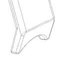
图1为本发明所述横突拉钩的示意图。Fig. 1 is a schematic diagram of the transverse process retractor of the present invention.
图2为本发明所述小关节拉钩的示意图。Fig. 2 is a schematic diagram of the facet joint retractor of the present invention.
图3为所述横突拉钩和小关节拉钩的新月型的凹口示意图。Fig. 3 is a schematic diagram of the crescent-shaped notch of the transverse process retractor and the facet joint retractor.
具体实施方式Detailed ways
下面对本发明技术方案进行详细说明,但是本发明的保护范围不局限于所述实施例。The technical solutions of the present invention will be described in detail below, but the protection scope of the present invention is not limited to the embodiments.
实施例1:如图1和2所示,一种脊柱后路微创置钉手术的暴露装置,包括横突拉钩和与其配合使用的小关节拉钩。Embodiment 1: As shown in Figures 1 and 2, an exposure device for minimally invasive posterior spinal surgery, including a transverse process retractor and a facet joint retractor used in conjunction with it.
所述横突拉钩由第一手柄1和第一拉钩体2构成,所述第一拉钩体2为夹角100度的L型金属条,所述第一拉钩体2的一端与第一手柄1固定连接,另一端往靠近第一手柄1的方向折弯,端头开有新月型的凹口。The transverse protruding hook is composed of a
所述小关节拉钩由第二手柄3和第二拉钩体4构成,所述第二拉钩体4为夹角80度的L型金属条,所述第二拉钩体4的一端与第二手柄3固定连接,另一端往靠近第二手柄3的方向折弯,端头开有新月型的凹口。The small joint retractor is composed of a
所述第一拉钩体2与第二拉钩体4均包括水平段和垂直段,所述第一手柄1和第二手柄3与水平段之间呈165度的折角,所述第一手柄1与第二手柄3均位于水平段与垂直段相对的一侧,所述第一拉钩体2与第二拉钩体4的另一端分别往靠近第一手柄1与第二手柄3的方向弯折10度,弯折长度均为5mm。The
所述第一手柄1和第二手柄3的连接端均呈鱼嘴状的扁平结构,所述第一手柄1和第二手柄3均长120mm,其中握持部长100mm,均为直径20mm圆柱体,所述第一手柄1和第二手柄3的握持部的外表面经粗糙化处理;所述第一拉钩体2与第二拉钩体4厚度均为2mm,宽度均为12mm;所述第一拉钩体2与第二拉钩体4的水平段长度均为100mm;所述第一拉钩体2的垂直段的长度为60或75mm;所述第二拉钩体4的垂直段的长度为50或65mm。The connection ends of the
所述横突拉钩的垂直段的外侧设有为椎弓根置入提示进针点和方向的指示线5。The outer side of the vertical section of the transverse process retractor is provided with an
如上所述,尽管参照特定的优选实施例已经表示和表述了本发明,但其不得解释为对本发明自身的限制。在不脱离所附权利要求定义的本发明的精神和范围前提下,可对其在形式上和细节上作出各种变化。As stated above, while the invention has been shown and described with reference to certain preferred embodiments, this should not be construed as limiting the invention itself. Various changes in form and details may be made therein without departing from the spirit and scope of the invention as defined by the appended claims.
Claims (6)
Translated fromChinesePriority Applications (6)
| Application Number | Priority Date | Filing Date | Title |
|---|---|---|---|
| CN201310035400.1ACN103110437B (en) | 2013-01-30 | 2013-01-30 | Exposure device for spinal posterior minimally invasive surgery nailing |
| CN2013200514665UCN203059799U (en) | 2013-01-30 | 2013-01-30 | Exposure device for spinal posterior minimally invasive nailing surgery |
| US14/764,797US9439641B2 (en) | 2013-01-30 | 2013-11-13 | Exposure apparatus for posterior spinal minimally invasive screw placement surgery |
| EP13873354.8AEP2952139B1 (en) | 2013-01-30 | 2013-11-13 | Exposure apparatus for spinal posterior minimally invasive screw fixation surgery |
| ES13873354.8TES2673146T3 (en) | 2013-01-30 | 2013-11-13 | Exposure apparatus for minimally invasive posterior spinal screw fixation surgery |
| PCT/CN2013/087037WO2014117562A1 (en) | 2013-01-30 | 2013-11-13 | Exposure apparatus for spinal posterior minimally invasive screw fixation surgery |
Applications Claiming Priority (2)
| Application Number | Priority Date | Filing Date | Title |
|---|---|---|---|
| CN201310035400.1ACN103110437B (en) | 2013-01-30 | 2013-01-30 | Exposure device for spinal posterior minimally invasive surgery nailing |
| CN2013200514665UCN203059799U (en) | 2013-01-30 | 2013-01-30 | Exposure device for spinal posterior minimally invasive nailing surgery |
Publications (2)
| Publication Number | Publication Date |
|---|---|
| CN103110437Atrue CN103110437A (en) | 2013-05-22 |
| CN103110437B CN103110437B (en) | 2015-02-11 |
Family
ID=54361245
Family Applications (2)
| Application Number | Title | Priority Date | Filing Date |
|---|---|---|---|
| CN2013200514665UExpired - Fee RelatedCN203059799U (en) | 2013-01-30 | 2013-01-30 | Exposure device for spinal posterior minimally invasive nailing surgery |
| CN201310035400.1AActiveCN103110437B (en) | 2013-01-30 | 2013-01-30 | Exposure device for spinal posterior minimally invasive surgery nailing |
Family Applications Before (1)
| Application Number | Title | Priority Date | Filing Date |
|---|---|---|---|
| CN2013200514665UExpired - Fee RelatedCN203059799U (en) | 2013-01-30 | 2013-01-30 | Exposure device for spinal posterior minimally invasive nailing surgery |
Country Status (5)
| Country | Link |
|---|---|
| US (1) | US9439641B2 (en) |
| EP (1) | EP2952139B1 (en) |
| CN (2) | CN203059799U (en) |
| ES (1) | ES2673146T3 (en) |
| WO (1) | WO2014117562A1 (en) |
Cited By (8)
| Publication number | Priority date | Publication date | Assignee | Title |
|---|---|---|---|---|
| WO2014117561A1 (en)* | 2013-01-30 | 2014-08-07 | 南京医科大学第一附属医院 | Exposure apparatus for paraspinal muscle clearance approach with small incision on spinal posterior |
| WO2014117562A1 (en)* | 2013-01-30 | 2014-08-07 | 南京医科大学第一附属医院 | Exposure apparatus for spinal posterior minimally invasive screw fixation surgery |
| CN106264629A (en)* | 2016-11-04 | 2017-01-04 | 山东大学第二医院 | Scope skull base surgery drag hook and method |
| CN106667535A (en)* | 2016-12-02 | 2017-05-17 | 彭国光 | Mandibular rumas hook |
| CN107638199A (en)* | 2017-10-24 | 2018-01-30 | 浙江科惠医疗器械股份有限公司 | Lumbar vertebrae dypass is minimally invasive to appear accessory part |
| CN109330648A (en)* | 2018-11-22 | 2019-02-15 | 南昌大学第二附属医院 | Anterior cervical traction device and system |
| CN112353439A (en)* | 2020-11-26 | 2021-02-12 | 哈尔滨医科大学 | Muscle spreader suitable for spine Wiltse approach operation |
| CN112656462A (en)* | 2020-12-25 | 2021-04-16 | 河北医科大学第三医院 | Pelvis operation retractor |
Families Citing this family (5)
| Publication number | Priority date | Publication date | Assignee | Title |
|---|---|---|---|---|
| CN107802329B (en)* | 2017-11-21 | 2024-02-13 | 中国人民解放军第四五五医院 | Spinal puncture positioning auxiliary device |
| FR3086159B1 (en)* | 2018-09-21 | 2021-07-23 | Allyon | SOFT TISSUE SPREADING TOOL COVERING LUMBAR VERTEBRA |
| US12171419B2 (en) | 2021-10-06 | 2024-12-24 | K2M, Inc. | Offset Hohmann |
| CN113974720B (en)* | 2021-11-09 | 2023-06-23 | 西安市红会医院 | A surgical instrument used to expose the acetabulum |
| US20240293113A1 (en)* | 2023-03-03 | 2024-09-05 | Foot Innovations, Llc | Retractor device |
Citations (8)
| Publication number | Priority date | Publication date | Assignee | Title |
|---|---|---|---|---|
| US5035232A (en)* | 1987-10-24 | 1991-07-30 | Aesculap Ag | Retractor |
| US5944658A (en)* | 1997-09-23 | 1999-08-31 | Koros; Tibor B. | Lumbar spinal fusion retractor and distractor system |
| CN2618567Y (en)* | 2003-05-16 | 2004-06-02 | 天津医科大学总医院 | Micro trauma spinal nerve specific hook |
| CN201290705Y (en)* | 2008-11-28 | 2009-08-19 | 上海市第一人民医院 | Holding type art transverse process draw-hook |
| CN201537102U (en)* | 2009-11-25 | 2010-08-04 | 黄志海 | Forked hollow vertebral plate draw hook |
| CN102166125A (en)* | 2011-04-23 | 2011-08-31 | 浙江大学 | Set of appliances for posterior lumbar interbody minimally invasive fusion |
| US8083780B2 (en)* | 2009-04-23 | 2011-12-27 | Custom Spine, Inc. | Spinal fixation mechanism |
| CN203059799U (en)* | 2013-01-30 | 2013-07-17 | 南京医科大学第一附属医院 | Exposure device for spinal posterior minimally invasive nailing surgery |
Family Cites Families (8)
| Publication number | Priority date | Publication date | Assignee | Title |
|---|---|---|---|---|
| US4817587A (en)* | 1987-08-31 | 1989-04-04 | Janese Woodrow W | Ring para-spinal retractor |
| CN2383475Y (en)* | 1999-07-15 | 2000-06-21 | 郝振海 | Retractor for vertebral lamina |
| WO2002060330A1 (en) | 2001-01-29 | 2002-08-08 | Stephen Ritland | Retractor and method for spinal pedicle screw placement |
| US7455639B2 (en)* | 2004-09-20 | 2008-11-25 | Stephen Ritland | Opposing parallel bladed retractor and method of use |
| CN2910132Y (en)* | 2006-05-17 | 2007-06-13 | 傅一山 | Retractor for microwound spine |
| EP2490598A1 (en) | 2009-10-21 | 2012-08-29 | Thompson Surgical Instruments, Inc. | Retractor system for anterior cervical spine surgery |
| US20130138036A1 (en)* | 2010-04-07 | 2013-05-30 | Clifford T. Solomon | Surgical implements with suction and irrigation passages |
| US9510812B2 (en)* | 2011-05-18 | 2016-12-06 | Automated Medical Products Corporation | Telescoping surgical support and retractor system |
- 2013
- 2013-01-30CNCN2013200514665Upatent/CN203059799U/ennot_activeExpired - Fee Related
- 2013-01-30CNCN201310035400.1Apatent/CN103110437B/enactiveActive
- 2013-11-13WOPCT/CN2013/087037patent/WO2014117562A1/enactiveApplication Filing
- 2013-11-13EPEP13873354.8Apatent/EP2952139B1/ennot_activeNot-in-force
- 2013-11-13ESES13873354.8Tpatent/ES2673146T3/enactiveActive
- 2013-11-13USUS14/764,797patent/US9439641B2/ennot_activeExpired - Fee Related
Patent Citations (8)
| Publication number | Priority date | Publication date | Assignee | Title |
|---|---|---|---|---|
| US5035232A (en)* | 1987-10-24 | 1991-07-30 | Aesculap Ag | Retractor |
| US5944658A (en)* | 1997-09-23 | 1999-08-31 | Koros; Tibor B. | Lumbar spinal fusion retractor and distractor system |
| CN2618567Y (en)* | 2003-05-16 | 2004-06-02 | 天津医科大学总医院 | Micro trauma spinal nerve specific hook |
| CN201290705Y (en)* | 2008-11-28 | 2009-08-19 | 上海市第一人民医院 | Holding type art transverse process draw-hook |
| US8083780B2 (en)* | 2009-04-23 | 2011-12-27 | Custom Spine, Inc. | Spinal fixation mechanism |
| CN201537102U (en)* | 2009-11-25 | 2010-08-04 | 黄志海 | Forked hollow vertebral plate draw hook |
| CN102166125A (en)* | 2011-04-23 | 2011-08-31 | 浙江大学 | Set of appliances for posterior lumbar interbody minimally invasive fusion |
| CN203059799U (en)* | 2013-01-30 | 2013-07-17 | 南京医科大学第一附属医院 | Exposure device for spinal posterior minimally invasive nailing surgery |
Non-Patent Citations (3)
| Title |
|---|
| 张文捷等: "经椎旁肌间隙入路治疗胸腰椎骨折", 《脊柱外科杂志》* |
| 胡建伟: "腰椎椎旁肌间隙入路的解剖学研究及其在腰椎后路融合术的临床应用", 《万方数据库》* |
| 陈宣煌等: "小切口椎旁肌间隙入路腰椎后路融合术的临床研究", 《实用临床医学杂志》* |
Cited By (11)
| Publication number | Priority date | Publication date | Assignee | Title |
|---|---|---|---|---|
| WO2014117561A1 (en)* | 2013-01-30 | 2014-08-07 | 南京医科大学第一附属医院 | Exposure apparatus for paraspinal muscle clearance approach with small incision on spinal posterior |
| WO2014117562A1 (en)* | 2013-01-30 | 2014-08-07 | 南京医科大学第一附属医院 | Exposure apparatus for spinal posterior minimally invasive screw fixation surgery |
| US9439638B2 (en) | 2013-01-30 | 2016-09-13 | The First Affiliated Hospital Of Nanjing Medical University | Exposure apparatus for paraspinal muscle clearance approach with posteriorspinal small incision |
| US9439641B2 (en) | 2013-01-30 | 2016-09-13 | The First Affiliated Hospital Of Nanjing Medical University | Exposure apparatus for posterior spinal minimally invasive screw placement surgery |
| CN106264629A (en)* | 2016-11-04 | 2017-01-04 | 山东大学第二医院 | Scope skull base surgery drag hook and method |
| CN106667535A (en)* | 2016-12-02 | 2017-05-17 | 彭国光 | Mandibular rumas hook |
| CN107638199A (en)* | 2017-10-24 | 2018-01-30 | 浙江科惠医疗器械股份有限公司 | Lumbar vertebrae dypass is minimally invasive to appear accessory part |
| CN107638199B (en)* | 2017-10-24 | 2024-05-31 | 浙江科惠医疗器械股份有限公司 | Lumbar vertebra side road minimally invasive exposure auxiliary assembly |
| CN109330648A (en)* | 2018-11-22 | 2019-02-15 | 南昌大学第二附属医院 | Anterior cervical traction device and system |
| CN112353439A (en)* | 2020-11-26 | 2021-02-12 | 哈尔滨医科大学 | Muscle spreader suitable for spine Wiltse approach operation |
| CN112656462A (en)* | 2020-12-25 | 2021-04-16 | 河北医科大学第三医院 | Pelvis operation retractor |
Also Published As
| Publication number | Publication date |
|---|---|
| ES2673146T3 (en) | 2018-06-20 |
| US20150366549A1 (en) | 2015-12-24 |
| CN203059799U (en) | 2013-07-17 |
| EP2952139A1 (en) | 2015-12-09 |
| CN103110437B (en) | 2015-02-11 |
| US9439641B2 (en) | 2016-09-13 |
| WO2014117562A1 (en) | 2014-08-07 |
| EP2952139A4 (en) | 2016-12-07 |
| EP2952139B1 (en) | 2018-04-18 |
Similar Documents
| Publication | Publication Date | Title |
|---|---|---|
| CN103110437B (en) | Exposure device for spinal posterior minimally invasive surgery nailing | |
| CN103126731B (en) | Exposure device for vertebral column back-way small-incision paraspinal muscle clearance admission passage | |
| CN204410951U (en) | A kind of first metatarsal osteotomy of distal plate | |
| US20100256687A1 (en) | Fixation Device and Method of Use for a Ludloff Osteotomy Procedure | |
| CN107280751B (en) | Lateral edge anatomic locking plate of scapula for scapula fractures and its use | |
| CN201684009U (en) | Calcaneal minimally invasive anatomical locking plate | |
| CN204995572U (en) | Dentata gorge portion fracture individuation pulling force screw navigation template | |
| CN103110438B (en) | Distraction maintenance device for small incision for posterior minimally invasive screw fixation for vertebral column of patient | |
| CN204931830U (en) | A kind of pedicle of vertebral arch fixed system | |
| CN203089239U (en) | Distraction maintaining device for minimally invasive screw setting small incision of spinal posterior approach | |
| WO2017107883A1 (en) | Screw-rod fixation device specially used for posterior atlantoaxial vertebrae | |
| CN203252731U (en) | Personalized fixing auxiliary device in lumbar vertebra | |
| CN204765759U (en) | Angle pedicle of vertebral arch hook of violently hitching | |
| CN203059916U (en) | Vertebral pedicle positioner for spinal posterior minimally invasive nailing | |
| CN206792472U (en) | A kind of flexible intramedullary nail with pressurization anti-rotation function | |
| CN215778546U (en) | Dissection locking device for ulna coronal process fracture | |
| CN204410944U (en) | A kind of patella fixing device | |
| CN212140565U (en) | Internal fixator for dislocation of ribs and transverse process and rib fracture under endoscope | |
| CN217244755U (en) | Point type reduction forceps for assisting fracture reduction in orthopedic surgery | |
| CN211911720U (en) | Cortex bone track screw fixation guide plate for lumbar vertebra vertebral plate osteotomy | |
| CN209422091U (en) | A semi-bonded anti-skid guide plate | |
| CN207640480U (en) | Tension band wire locking hook plate | |
| WO2014117560A1 (en) | Vertebral arch pedicle positioner for spinal posterior minimally invasive screw fixation | |
| CN210121170U (en) | A bilateral lamina screw guide | |
| CN207323530U (en) | Thoracolumbar disk posterior ligament complex Hui Zhi anatomical form titanium plates |
Legal Events
| Date | Code | Title | Description |
|---|---|---|---|
| C06 | Publication | ||
| PB01 | Publication | ||
| C10 | Entry into substantive examination | ||
| SE01 | Entry into force of request for substantive examination | ||
| C14 | Grant of patent or utility model | ||
| GR01 | Patent grant | ||
| CB03 | Change of inventor or designer information | Inventor after:Cao Yile Inventor after:Cao Xiaojian Inventor after:Li Haijun Inventor after:Xie Hao Inventor before:Cao Xiaojian Inventor before:Li Haijun Inventor before:Xie Hao | |
| CB03 | Change of inventor or designer information | ||
| TR01 | Transfer of patent right | Effective date of registration:20170818 Address after:Tianfu garden Gulou District of Nanjing city in Jiangsu province 210000 No. 87 room 704 Co-patentee after:No.1 Attached Hospital, Nanjing Medical Univ. Patentee after:Cao Yile Address before:210029 Guangzhou Road, Jiangsu, China, No. 300, No. Patentee before:No.1 Attached Hospital, Nanjing Medical Univ. | |
| TR01 | Transfer of patent right | ||
| TR01 | Transfer of patent right | Effective date of registration:20200330 Address after:210029 No. 300, Guangzhou Road, Nanjing, Jiangsu Patentee after:THE FIRST AFFILIATED HOSPITAL OF NANJING MEDICAL University Address before:210000 room 704, Tianfu garden 87, Gulou District, Nanjing, Jiangsu. Co-patentee before:THE FIRST AFFILIATED HOSPITAL OF NANJING MEDICAL University Patentee before:Cao Yile | |
| TR01 | Transfer of patent right | ||
| EE01 | Entry into force of recordation of patent licensing contract | Application publication date:20130522 Assignee:Nanjing Tuodao Medical Technology Co.,Ltd. Assignor:THE FIRST AFFILIATED HOSPITAL OF NANJING MEDICAL University Contract record no.:X2021980001284 Denomination of invention:An exposure device for minimally invasive posterior spinal nailing Granted publication date:20150211 License type:Exclusive License Record date:20210223 | |
| EE01 | Entry into force of recordation of patent licensing contract |