CN103109482A - Signal generating method and signal generating device - Google Patents
Signal generating method and signal generating deviceDownload PDFInfo
- Publication number
- CN103109482A CN103109482ACN2012800020663ACN201280002066ACN103109482ACN 103109482 ACN103109482 ACN 103109482ACN 2012800020663 ACN2012800020663 ACN 2012800020663ACN 201280002066 ACN201280002066 ACN 201280002066ACN 103109482 ACN103109482 ACN 103109482A
- Authority
- CN
- China
- Prior art keywords
- phase
- signal
- time
- symbol
- baseband signal
- Prior art date
- Legal status (The legal status is an assumption and is not a legal conclusion. Google has not performed a legal analysis and makes no representation as to the accuracy of the status listed.)
- Pending
Links
Images


Classifications
- H—ELECTRICITY
- H04—ELECTRIC COMMUNICATION TECHNIQUE
- H04B—TRANSMISSION
- H04B7/00—Radio transmission systems, i.e. using radiation field
- H04B7/02—Diversity systems; Multi-antenna system, i.e. transmission or reception using multiple antennas
- H04B7/04—Diversity systems; Multi-antenna system, i.e. transmission or reception using multiple antennas using two or more spaced independent antennas
- H04B7/06—Diversity systems; Multi-antenna system, i.e. transmission or reception using multiple antennas using two or more spaced independent antennas at the transmitting station
- H04B7/0613—Diversity systems; Multi-antenna system, i.e. transmission or reception using multiple antennas using two or more spaced independent antennas at the transmitting station using simultaneous transmission
- H04B7/0667—Diversity systems; Multi-antenna system, i.e. transmission or reception using multiple antennas using two or more spaced independent antennas at the transmitting station using simultaneous transmission of delayed versions of same signal
- H—ELECTRICITY
- H04—ELECTRIC COMMUNICATION TECHNIQUE
- H04B—TRANSMISSION
- H04B7/00—Radio transmission systems, i.e. using radiation field
- H04B7/02—Diversity systems; Multi-antenna system, i.e. transmission or reception using multiple antennas
- H04B7/04—Diversity systems; Multi-antenna system, i.e. transmission or reception using multiple antennas using two or more spaced independent antennas
- H04B7/0404—Diversity systems; Multi-antenna system, i.e. transmission or reception using multiple antennas using two or more spaced independent antennas the mobile station comprising multiple antennas, e.g. to provide uplink diversity
- H—ELECTRICITY
- H04—ELECTRIC COMMUNICATION TECHNIQUE
- H04B—TRANSMISSION
- H04B7/00—Radio transmission systems, i.e. using radiation field
- H04B7/02—Diversity systems; Multi-antenna system, i.e. transmission or reception using multiple antennas
- H04B7/04—Diversity systems; Multi-antenna system, i.e. transmission or reception using multiple antennas using two or more spaced independent antennas
- H04B7/06—Diversity systems; Multi-antenna system, i.e. transmission or reception using multiple antennas using two or more spaced independent antennas at the transmitting station
- H04B7/0613—Diversity systems; Multi-antenna system, i.e. transmission or reception using multiple antennas using two or more spaced independent antennas at the transmitting station using simultaneous transmission
- H04B7/0682—Diversity systems; Multi-antenna system, i.e. transmission or reception using multiple antennas using two or more spaced independent antennas at the transmitting station using simultaneous transmission using phase diversity (e.g. phase sweeping)
- H—ELECTRICITY
- H04—ELECTRIC COMMUNICATION TECHNIQUE
- H04B—TRANSMISSION
- H04B7/00—Radio transmission systems, i.e. using radiation field
- H04B7/02—Diversity systems; Multi-antenna system, i.e. transmission or reception using multiple antennas
- H04B7/04—Diversity systems; Multi-antenna system, i.e. transmission or reception using multiple antennas using two or more spaced independent antennas
- H04B7/06—Diversity systems; Multi-antenna system, i.e. transmission or reception using multiple antennas using two or more spaced independent antennas at the transmitting station
- H04B7/0697—Diversity systems; Multi-antenna system, i.e. transmission or reception using multiple antennas using two or more spaced independent antennas at the transmitting station using spatial multiplexing
- H—ELECTRICITY
- H04—ELECTRIC COMMUNICATION TECHNIQUE
- H04B—TRANSMISSION
- H04B7/00—Radio transmission systems, i.e. using radiation field
- H04B7/02—Diversity systems; Multi-antenna system, i.e. transmission or reception using multiple antennas
- H04B7/04—Diversity systems; Multi-antenna system, i.e. transmission or reception using multiple antennas using two or more spaced independent antennas
- H04B7/08—Diversity systems; Multi-antenna system, i.e. transmission or reception using multiple antennas using two or more spaced independent antennas at the receiving station
- H04B7/0837—Diversity systems; Multi-antenna system, i.e. transmission or reception using multiple antennas using two or more spaced independent antennas at the receiving station using pre-detection combining
- H04B7/0842—Weighted combining
- H—ELECTRICITY
- H04—ELECTRIC COMMUNICATION TECHNIQUE
- H04L—TRANSMISSION OF DIGITAL INFORMATION, e.g. TELEGRAPHIC COMMUNICATION
- H04L1/00—Arrangements for detecting or preventing errors in the information received
- H04L1/004—Arrangements for detecting or preventing errors in the information received by using forward error control
- H04L1/0045—Arrangements at the receiver end
- H04L1/0047—Decoding adapted to other signal detection operation
- H04L1/0048—Decoding adapted to other signal detection operation in conjunction with detection of multiuser or interfering signals, e.g. iteration between CDMA or MIMO detector and FEC decoder
- H—ELECTRICITY
- H04—ELECTRIC COMMUNICATION TECHNIQUE
- H04L—TRANSMISSION OF DIGITAL INFORMATION, e.g. TELEGRAPHIC COMMUNICATION
- H04L1/00—Arrangements for detecting or preventing errors in the information received
- H04L1/004—Arrangements for detecting or preventing errors in the information received by using forward error control
- H04L1/0056—Systems characterized by the type of code used
- H04L1/0071—Use of interleaving
- H—ELECTRICITY
- H04—ELECTRIC COMMUNICATION TECHNIQUE
- H04L—TRANSMISSION OF DIGITAL INFORMATION, e.g. TELEGRAPHIC COMMUNICATION
- H04L27/00—Modulated-carrier systems
- H04L27/18—Phase-modulated carrier systems, i.e. using phase-shift keying
- H04L27/20—Modulator circuits; Transmitter circuits
- H—ELECTRICITY
- H04—ELECTRIC COMMUNICATION TECHNIQUE
- H04L—TRANSMISSION OF DIGITAL INFORMATION, e.g. TELEGRAPHIC COMMUNICATION
- H04L27/00—Modulated-carrier systems
- H04L27/18—Phase-modulated carrier systems, i.e. using phase-shift keying
- H04L27/20—Modulator circuits; Transmitter circuits
- H04L27/2032—Modulator circuits; Transmitter circuits for discrete phase modulation, e.g. in which the phase of the carrier is modulated in a nominally instantaneous manner
- H04L27/2053—Modulator circuits; Transmitter circuits for discrete phase modulation, e.g. in which the phase of the carrier is modulated in a nominally instantaneous manner using more than one carrier, e.g. carriers with different phases
- H04L27/206—Modulator circuits; Transmitter circuits for discrete phase modulation, e.g. in which the phase of the carrier is modulated in a nominally instantaneous manner using more than one carrier, e.g. carriers with different phases using a pair of orthogonal carriers, e.g. quadrature carriers
- H—ELECTRICITY
- H04—ELECTRIC COMMUNICATION TECHNIQUE
- H04L—TRANSMISSION OF DIGITAL INFORMATION, e.g. TELEGRAPHIC COMMUNICATION
- H04L27/00—Modulated-carrier systems
- H04L27/26—Systems using multi-frequency codes
- H04L27/2601—Multicarrier modulation systems
- H04L27/2626—Arrangements specific to the transmitter only
- H04L27/2627—Modulators
- H04L27/2634—Inverse fast Fourier transform [IFFT] or inverse discrete Fourier transform [IDFT] modulators in combination with other circuits for modulation
- H—ELECTRICITY
- H04—ELECTRIC COMMUNICATION TECHNIQUE
- H04L—TRANSMISSION OF DIGITAL INFORMATION, e.g. TELEGRAPHIC COMMUNICATION
- H04L27/00—Modulated-carrier systems
- H04L27/26—Systems using multi-frequency codes
- H04L27/2601—Multicarrier modulation systems
- H04L27/2647—Arrangements specific to the receiver only
- H04L27/2649—Demodulators
- H04L27/26524—Fast Fourier transform [FFT] or discrete Fourier transform [DFT] demodulators in combination with other circuits for demodulation
- H—ELECTRICITY
- H04—ELECTRIC COMMUNICATION TECHNIQUE
- H04L—TRANSMISSION OF DIGITAL INFORMATION, e.g. TELEGRAPHIC COMMUNICATION
- H04L27/00—Modulated-carrier systems
- H04L27/32—Carrier systems characterised by combinations of two or more of the types covered by groups H04L27/02, H04L27/10, H04L27/18 or H04L27/26
- H04L27/34—Amplitude- and phase-modulated carrier systems, e.g. quadrature-amplitude modulated carrier systems
- H04L27/36—Modulator circuits; Transmitter circuits
- H04L27/366—Arrangements for compensating undesirable properties of the transmission path between the modulator and the demodulator
- H04L27/367—Arrangements for compensating undesirable properties of the transmission path between the modulator and the demodulator using predistortion
- H04L27/368—Arrangements for compensating undesirable properties of the transmission path between the modulator and the demodulator using predistortion adaptive predistortion
- H—ELECTRICITY
- H04—ELECTRIC COMMUNICATION TECHNIQUE
- H04L—TRANSMISSION OF DIGITAL INFORMATION, e.g. TELEGRAPHIC COMMUNICATION
- H04L5/00—Arrangements affording multiple use of the transmission path
- H04L5/0001—Arrangements for dividing the transmission path
- H04L5/0014—Three-dimensional division
- H04L5/0023—Time-frequency-space
- H—ELECTRICITY
- H04—ELECTRIC COMMUNICATION TECHNIQUE
- H04L—TRANSMISSION OF DIGITAL INFORMATION, e.g. TELEGRAPHIC COMMUNICATION
- H04L5/00—Arrangements affording multiple use of the transmission path
- H04L5/003—Arrangements for allocating sub-channels of the transmission path
- H04L5/0078—Timing of allocation
- H04L5/0082—Timing of allocation at predetermined intervals
- H—ELECTRICITY
- H04—ELECTRIC COMMUNICATION TECHNIQUE
- H04L—TRANSMISSION OF DIGITAL INFORMATION, e.g. TELEGRAPHIC COMMUNICATION
- H04L5/00—Arrangements affording multiple use of the transmission path
- H04L5/02—Channels characterised by the type of signal
- H04L5/12—Channels characterised by the type of signal the signals being represented by different phase modulations of a single carrier
Landscapes
- Engineering & Computer Science (AREA)
- Signal Processing (AREA)
- Computer Networks & Wireless Communication (AREA)
- Physics & Mathematics (AREA)
- Discrete Mathematics (AREA)
- General Physics & Mathematics (AREA)
- Mathematical Physics (AREA)
- Radio Transmission System (AREA)
- Reduction Or Emphasis Of Bandwidth Of Signals (AREA)
- Digital Transmission Methods That Use Modulated Carrier Waves (AREA)
- Stereo-Broadcasting Methods (AREA)
- Mobile Radio Communication Systems (AREA)
Abstract
Description
Translated fromChinese技术领域technical field
(与相关申请有关的参考)在2011年2月18日提出的日本专利申请2011-033771号、2011年3月9日提出的日本专利申请2011-051842号、2011年4月19日提出的日本专利申请2011-093544号、及2011年4月28日提出的日本专利申请2011-102101号中包含的权利要求、说明书、附图及说明书摘要的公开内容全部被引用于本申请中。(References related to related applications) Japanese Patent Application No. 2011-033771 filed on February 18, 2011, Japanese Patent Application No. 2011-051842 filed on March 9, 2011, Japanese Patent Application No. 2011-051842 filed on April 19, 2011 The disclosures of patent application No. 2011-093544 and Japanese patent application No. 2011-102101 filed on April 28, 2011, claims, specification, drawings, and abstract of the specification are incorporated herein by reference in their entirety.
本发明尤其涉及进行使用了多天线(multi-antenna)的通信的发送装置及接收装置。In particular, the present invention relates to a transmitting device and a receiving device that perform communication using a multi-antenna.
背景技术Background technique
以往,作为使用多天线的通信方法,例如有被称为MIMO(Multiple-Input Multiple-Output)的通信方法。在以MIMO为代表的多天线通信中,通过分别对多个系列的发送数据进行调制,并从不同的天线同时发送各调制信号,来提高数据的通信速度。Conventionally, as a communication method using multiple antennas, for example, there is a communication method called MIMO (Multiple-Input Multiple-Output). In multi-antenna communication represented by MIMO, a plurality of series of transmission data are modulated separately, and each modulated signal is simultaneously transmitted from different antennas, thereby increasing the data communication speed.
图23表示发送天线数为2、接收天线数为2、发送调制信号(发送流)数为2时的收发装置的结构的一例。在发送装置中,对编码后的数据进行交错,对交错后的数据进行调制,并进行频率替换等,从而生成发送信号,发送信号被从天线发送。此时,从发送天线在同一时刻按同一频率分别发送不同的调制信号的方式是空间复用MIMO方式。FIG. 23 shows an example of the configuration of a transmission and reception device when the number of transmission antennas is two, the number of reception antennas is two, and the number of transmission modulated signals (transmission streams) is two. In the transmission device, the coded data is interleaved, the interleaved data is modulated, frequency replacement is performed, etc., to generate a transmission signal, and the transmission signal is transmitted from the antenna. In this case, the method of transmitting different modulated signals at the same frequency at the same time from the transmitting antenna is the spatial multiplexing MIMO method.
此时,在专利文献1中提出了一种在每个发送天线中具备不同的交错模式的发送装置。也就是说,在图23的发送装置中2个交错器(πa、πb)具有相互不同的交错模式。而且,在接收装置中,如非专利文献1、非专利文献2所示,通过反复进行利用软值的检波方法(图23中的MIMO detector),来提高接收品质。In this case,
可是,作为无线通信中的实际传播环境的模型,存在以瑞利衰落环境为代表的NLOS(non-line of sight)环境和以莱斯衰落环境为代表的LOS(line of sight)环境。在发送装置中发送单个调制信号,在接收装置中对由多个接收天线接收到的信号进行最大比合成、并对最大比合成后的信号进行解调及解码的情况下,在LOS环境、特别是表示直接波的接收功率相对于散射波的接收功率的的大小的莱斯因子较大的环境下,能够获得良好的接收品质。但是,根据传输方式(例如空间复用MIMO传输方式)的不同,会产生若莱斯因子增大则接收品质劣化的问题。(参见非专利文献3)However, there are NLOS (non-line of sight) environments represented by Rayleigh fading environments and LOS (line of sight) environments represented by Rice fading environments as models of actual propagation environments in wireless communications. In the case of transmitting a single modulated signal in the transmitting device, performing maximum ratio combination of signals received by multiple receiving antennas in the receiving device, and demodulating and decoding the maximum ratio combined signal, the LOS environment, especially In an environment where the Rice factor representing the magnitude of the received power of the direct wave relative to the received power of the scattered wave is large, good reception quality can be obtained. However, depending on the transmission scheme (for example, the spatial multiplexing MIMO transmission scheme), there is a problem that reception quality deteriorates when the Rice factor increases. (See Non-Patent Document 3)
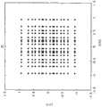
图24(A)(B)表示,在瑞利衰落环境及莱斯因子K=3、10、16dB的莱斯衰落环境下,对LDPC(low-density parity-check)编码后的数据进行了2×2(2天线发送、2天线接收)空间复用MIMO传输的情况下的BER(Bit Error Rate)特性(纵轴:BER,横轴:SNR(signal-to-noise powerratio))的模拟结果的一例。图24(A)表示,不进行反复检波的Max-log-APP(参见非专利文献1、非专利文献2)(APP:a posterior probability))的BER特性,图24(B)表示,进行反复检波后的Max-log-APP(参见非专利文献1、非专利文献2)(反复次数为5次)的BER特性。从图24(A)(B)可知,无论是否进行反复检波,在空间复用MIMO系统中,都能够确认到若莱斯因子增大则接收品质变坏的情况。由此可知,具有“在空间复用MIMO系统中,在传播环境变得稳定时接收品质变坏”这样的、在以往的发送单个调制信号的系统中不存在的空间复用MIMO系统固有的课题。Figure 24(A)(B) shows that in the Rayleigh fading environment and the Rice fading environment with Rice factor K=3, 10, 16dB, the LDPC (low-density parity-check) encoded data is 2 Simulation results of BER (Bit Error Rate) characteristics (vertical axis: BER, horizontal axis: SNR (signal-to-noise powerratio)) in the case of ×2 (2 antenna transmission, 2 antenna reception) spatial multiplexing MIMO transmission an example. Fig. 24(A) shows the BER characteristics of Max-log-APP (see Non-Patent
广播或多播通信是必须适应各种各样的传播环境的服务,用户持有的接收机和广播站之间的电波传播环境当然有可能是LOS环境。将具有上述课题的空间复用MIMO系统应用到广播或多播通信中时,在接收机中电波的接收电场强度较高,但是可能产生因接收品质的劣化而无法接受服务的现象。也就是说,为了在广播或多播通信中采用空间复用MIMO系统,期望在NLOS环境及LOS环境的任一个的情况下,都获得一定程度的接收品质的MIMO传输方式的开发。Broadcast or multicast communication is a service that must be adapted to various propagation environments, and of course the radio wave propagation environment between a receiver owned by a user and a broadcast station may be a LOS environment. When the spatial multiplexing MIMO system having the above-mentioned problems is applied to broadcast or multicast communication, the receiving electric field strength of the radio wave is high in the receiver, but service may not be accepted due to deterioration of reception quality. That is, in order to employ a spatial multiplexing MIMO system in broadcast or multicast communication, development of a MIMO transmission scheme that achieves a certain level of reception quality in both the NLOS environment and the LOS environment is desired.
在非专利文献8中,阐述了从来自通信对象的反馈信息中选择用于预编码的码本(预编码矩阵(也称为预编码权重矩阵))的方法,但是如上所述,像广播或多播通信那样,在无法得到来自通信对象的反馈信息的状况下进行预编码的方法,却完全没有记述。In
另一方面,在非专利文献4中,阐述了在没有反馈信息时也能够应用的、随着时间来切换预编码矩阵的方法。在该文献中,阐述了作为用于预编码的矩阵而使用酉矩阵、并且随机切换酉矩阵的方法,但是对于上述的对于LOS环境下的接收品质的劣化的应用方法却完全没有记述,仅记述了随机切换。当然,完全没有记载用于改善LOS环境的接收品质的劣化的预编码方法以及预编码矩阵的构成方法。On the other hand, Non-Patent
在先技术文献prior art literature
专利文献1:国际公开第2005/050885号Patent Document 1: International Publication No. 2005/050885
非专利文献1:“Achieving near-capacity on a multiple-antennachannel”IEEE Transaction on communications,vol.51,no.3,pp.389-399,March2003.Non-Patent Document 1: "Achieving near-capacity on a multiple-antennachannel" IEEE Transaction on communications, vol.51, no.3, pp.389-399, March 2003.
非专利文献2:“Performance analysis and design optimization ofLDPC-coded MIMO OFDM systems”IEEE Trans.Signal Processing.,vol.52,no.2,pp.348-361,Feb.2004.Non-Patent Document 2: "Performance analysis and design optimization of LDPC-coded MIMO OFDM systems" IEEE Trans.Signal Processing., vol.52, no.2, pp.348-361, Feb.2004.
非专利文献3:“BER performance evaluation in2x2MIMO spatialmultiplexing systems under Rician fading channels,”IEICE Trans.Fundamentals,vol.E91-A,no.10,pp.2798-2807,Oct.2008.Non-Patent Document 3: "BER performance evaluation in2x2MIMO spatialmultiplexing systems under Rician fading channels," IEICE Trans.Fundamentals, vol.E91-A, no.10, pp.2798-2807, Oct.2008.
非专利文献4:“Turbo space-time codes with time varying lineartransformations,”IEEE Trans.Wireless communications,vol.6,no.2,pp.486-493,Feb.2007.Non-Patent Document 4: "Turbo space-time codes with time varying linear transformations," IEEE Trans.Wireless communications, vol.6, no.2, pp.486-493, Feb.2007.
非专利文献5:“Likelihood function for QR-MLD suitable forsoft-decision turbo decoding and its performance,”IEICE Trans.Commun.,vol.E88-B,no.1,pp.47-57,Jan.2004.Non-Patent Document 5: "Likelihood function for QR-MLD suitable for soft-decision turbo decoding and its performance," IEICE Trans.Commun., vol.E88-B, no.1, pp.47-57, Jan.2004.
非专利文献6:“Shannon限界への道標:“Paral lel concatenated(Turbo)coding”,“Turbo(iterative)decoding”とその周辺”電子情報通信学会、信学技法IT98-51Non-Patent Document 6: "Shannon Boundary への Beacon: "Paral lel concatenated (Turbo) coding", "Turbo (iterative) decoding" and その周辺" Institute of Electronic Information and Communication, Information Technology IT98-51
非专利文献7:“Advanced signal processing for PLCs:Wavelet-OFDM,”Proc.of IEEE International symposium on ISPLC2008,pp.187-192,2008.Non-Patent Document 7: "Advanced signal processing for PLCs: Wavelet-OFDM," Proc.of IEEE International symposium on ISPLC2008, pp.187-192, 2008.
非专利文献8:D.J.Love,and R.W.heath,Jr.,“Limitedfeedback unitary precoding for spatial multiplexing systems,”IEEETrans.Inf.Theory,vol.51,no.8,pp.2967-1976,Aug.2005.Non-Patent Document 8: D.J.Love, and R.W.heath, Jr., "Limited feedback unitary precoding for spatial multiplexing systems," IEEETrans.Inf.Theory, vol.51, no.8, pp.2967-1976, Aug.2005.
非专利文献9:DVB Document A122,Framing structure,channelcoding and modulation for a second generation digital terrestrialtelevision broadcasting system(DVB-T2),June2008.Non-Patent Document 9: DVB Document A122, Framing structure, channelcoding and modulation for a second generation digital terrestrialtelevision broadcasting system (DVB-T2), June2008.
非专利文献10:L.Vangelista,N.Benvenuto,and S.Tomasin,“Key technologies for next-generation terrestrial digitaltelevision standard DVB-T2,”IEEE Commun.Magazine,vo.47,no.10,pp.146-153,Oct.2009.Non-Patent Document 10: L.Vangelista, N.Benvenuto, and S.Tomasin, "Key technologies for next-generation terrestrial digitaltelevision standard DVB-T2," IEEE Commun.Magazine, vo.47, no.10, pp.146- 153, Oct. 2009.
非专利文献11:T.Ohgane,T.Nishimura,and Y.Ogawa,“Application of space division multiplexing and those performancein a MIMO channel,”IEICE Trans.Commun.,vo.88-B,no.5,pp.1843-1851,May2005.Non-Patent Document 11: T.Ohgane, T.Nishimura, and Y.Ogawa, "Application of space division multiplexing and those performance in a MIMO channel," IEICE Trans.Commun., vo.88-B, no.5, pp. 1843-1851, May 2005.
非专利文献12:R.G.Gallager,“Low-density parity-checkcodes,”IRE Trans.Inform.Theory,IT-8,pp-21-28,1962.Non-Patent Document 12: R.G. Gallager, "Low-density parity-checkcodes," IRE Trans.Inform.Theory, IT-8, pp-21-28, 1962.
非专利文献13:D.J.C.Mackay,“Good error-correcting codesbased on very sparse matrices,”IEEE Trans.Inform.Theory,vol.45,no.2,pp399-431,March1999.Non-Patent Document 13: D.J.C.Mackay, "Good error-correcting codes based on very sparse matrices," IEEE Trans.Inform.Theory, vol.45, no.2, pp399-431, March1999.
非专利文献14:ETSI EN302307,“Second generation framingstructure,channel coding and modulation systems for broadcasting,interactive services,news gathering and other broadband satelliteapplications,“v.1.1.2,June2006.Non-Patent Document 14: ETSI EN302307, "Second generation framing structure, channel coding and modulation systems for broadcasting, interactive services, news gathering and other broadband satellite applications," v.1.1.2, June2006.
非专利文献15:Y.-L.Ueng,and C.-C.Cheng,“a fast-convergencedecoding method and memory-efficient VLSI decoder architecture forirregular LDPC codes in the IEEE802.16e standards,”IEEE VTC-2007Fall,pp.1255-1259.Non-Patent Document 15: Y.-L.Ueng, and C.-C.Cheng, "a fast-convergence decoding method and memory-efficient VLSI decoder architecture for irregular LDPC codes in the IEEE802.16e standards," IEEE VTC-2007Fall, pp .1255-1259.
非专利文献16:S.M.Alamouti、“A simple transmit diversitytechnique for wireless communications,”IEEE J.Select.AreasCommun.,vol.16,no.8,pp.1451-1458,Oct1998.Non-Patent Document 16: S.M.Alamouti, "A simple transmit diversity technique for wireless communications," IEEE J.Select.AreasCommun., vol.16, no.8, pp.1451-1458, Oct1998.
非专利文献17:V.Tarokh,H.Jafrkhani,and A.R.Calderbank、“Space-time block coding for wireless communications:Performanceresults、”IEEE J.Select.Areas Commun.,vol.17,no.3,no.3,pp.451―460,March1999.Non-Patent Document 17: V.Tarokh, H.Jafrkhani, and A.R. Calderbank, "Space-time block coding for wireless communications: Performance results," IEEE J.Select.Areas Commun., vol.17, no.3, no.3 , pp.451-460, March 1999.
发明内容Contents of the invention
本发明的目的在于,提供一种能够改善LOS环境下的接收品质的MIMO系统。An object of the present invention is to provide a MIMO system capable of improving reception quality in a LOS environment.
本发明所涉及的信号生成方法用来从多个基带信号生成以同一频带且同一时刻发送的多个信号,其特征为,对于从第1多个比特所生成的第1基带信号s1和从第2多个比特所生成的第2基带信号s2的双方执行相位变更,生成相位变更后的第1基带信号s1'和相位变更后的第2基带信号s2',将上述相位变更后的第1基带信号s1'放大u倍,将上述相位变更后的第2基带信号s2'放大v倍,u和v是相互不同的实数,对将上述相位变更后的第1基带信号s1'放大u倍后的信号和将上述相位变更后的第2基带信号s2'放大v倍后的信号,实施依据规定矩阵F的加权合成,生成第1加权合成信号z1和第2加权合成信号z2,来作为以上述同一频带且同一时刻发送的多个信号,上述第1加权合成信号z1及上述第2加权合成信号z2满足(z1、z2)T=F(u×s1',v×s2')T,对上述放大u倍后的第1基带信号s1及上述放大v倍后的第2基带信号s2实施的相位变更量分别是一边切换N个相位变更量的候选一边选择出的一个相位变更量,上述N个相位变更量的各自在规定的期间内至少被选择一次。The signal generation method according to the present invention is used to generate a plurality of signals transmitted in the same frequency band and at the same time from a plurality of baseband signals, and is characterized in that, for the first baseband signal s1 generated from the first plurality of bits and the first baseband signal s1 generated from the first plurality of bits, Phase change is performed on both sides of the second baseband signal s2 generated by a plurality of bits to generate a phase-changed first baseband signal s1' and a phase-changed second baseband signal s2', and the above-mentioned phase-changed first baseband signal The signal s1' is amplified by u times, and the second baseband signal s2' after the above phase change is amplified by v times, u and v are real numbers different from each other, and the first baseband signal s1' after the above phase change is amplified by u times signal and the signal obtained by amplifying the second baseband signal s2' after the above-mentioned phase change by v times, implement weighted combination according to the predetermined matrix F, and generate the first weighted combined signal z1 and the second weighted combined signal z2 as the same Frequency band and multiple signals transmitted at the same time, the above-mentioned first weighted composite signal z1 and the above-mentioned second weighted composite signal z2 satisfy (z1, z2)T = F (u×s1', v×s2')T , the above-mentioned amplification The phase change amount implemented by the u-folded first baseband signal s1 and the v-folded second baseband signal s2 is a phase change amount selected while switching N phase change amount candidates, and the above N phase change amount Each of the amount of change is selected at least once within a predetermined period.
另外,本发明所涉及的信号生成装置用来从多个基带信号生成以同一频带且同一时刻发送的多个信号,其特征为,具备:相位变更部,对从第1多个比特所生成的第1基带信号s1和从第2多个比特所生成的第2基带信号s2的双方执行相位变更,生成相位变更后的第1基带信号s1'和相位变更后的第2基带信号s2';功率变更部,将上述相位变更后的第1基带信号s1'放大u倍,将上述相位变更后的第2基带信号s2'放大v倍,u和v是相互不同的实数;加权合成部,对于将上述相位变更后的第1基带信号s1'放大u倍后的信号和将上述相位变更后的第2基带信号s2'放大v倍后的信号,实施依据规定矩阵F的加权合成,生成第1加权合成信号z1和第2加权合成信号z2,来作为以上述同一频带且同一时刻发送的多个信号;上述第1加权合成信号z1及上述第2加权合成信号z2满足(z1、z2)T=F(u×s1',v×s2')T,对上述放大u倍后的第1基带信号s1及上述放大v倍后的第2基带信号s2实施的相位变更量分别是一边切换N个相位变更量的候选一边选择出的一个相位变更量,上述N个相位变更量的候选的各自在规定的期间内至少被选择一次。In addition, the signal generation device according to the present invention is used to generate a plurality of signals transmitted at the same frequency band and at the same time from a plurality of baseband signals, and is characterized in that it includes: Both of the first baseband signal s1 and the second baseband signal s2 generated from the second plurality of bits perform phase change to generate the first baseband signal s1' after the phase change and the second baseband signal s2' after the phase change; power The changing part amplifies the first baseband signal s1' after the above-mentioned phase change by u times, and amplifies the second baseband signal s2' after the above-mentioned phase change by v times, and u and v are real numbers different from each other; The first baseband signal s1' after the phase change is amplified by u times and the second baseband signal s2' after the phase change is amplified by v times, and the weighted combination according to the predetermined matrix F is performed to generate the first weighted The composite signal z1 and the second weighted composite signal z2 are used as a plurality of signals transmitted in the same frequency band and at the same time; the first weighted composite signal z1 and the second weighted composite signal z2 satisfy (z1, z2)T = F (u×s1', v×s2')T , the amount of phase change implemented on the first baseband signal s1 amplified by u times and the second baseband signal s2 amplified by v times is respectively N phase changes while switching Each of the N phase change amount candidates is selected at least once within a predetermined period.
这样,根据本发明,能够提供改善LOS环境下的接收品质的劣化的信号生成方法、信号生成装置,所以能够在广播或多播通信中对预想内的用户提供品质较高的服务。As described above, according to the present invention, it is possible to provide a signal generation method and a signal generation device that improve reception quality degradation in an LOS environment, so that high-quality services can be provided to expected users in broadcast or multicast communication.
附图说明Description of drawings
图1是空间复用MIMO传输系统中的收发装置的结构例。FIG. 1 is a configuration example of a transmitting and receiving device in a spatial multiplexing MIMO transmission system.
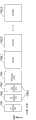
图2是帧结构的一例。FIG. 2 is an example of a frame structure.
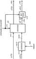
图3是应用相位变更方法时的发送装置的结构例。FIG. 3 is a configuration example of a transmission device when a phase changing method is applied.
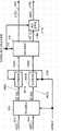
图4是应用相位变更方法时的发送装置的结构例。FIG. 4 is a configuration example of a transmission device when a phase change method is applied.
图5是帧结构的例子。Fig. 5 is an example of a frame structure.
图6是相位变更方法的例子。FIG. 6 is an example of a phase changing method.
图7是接收装置的结构例。Fig. 7 is a configuration example of a receiving device.
图8是接收装置的信号处理部的结构例。FIG. 8 is a configuration example of a signal processing unit of a receiving device.
图9是接收装置的信号处理部的结构例。FIG. 9 is a configuration example of a signal processing unit of a receiving device.
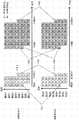
图10是解码处理方法。Fig. 10 is a decoding processing method.
图11是接收状态的例子。Fig. 11 is an example of a receiving state.
图12是应用相位变更方法时的发送装置的结构例。Fig. 12 is a configuration example of a transmission device when a phase changing method is applied.
图13是应用相位变更方法时的发送装置的结构例。Fig. 13 is a configuration example of a transmission device when a phase changing method is applied.
图14是帧结构的例子。Fig. 14 is an example of a frame structure.
图15是帧结构的例子。Fig. 15 is an example of a frame structure.
图16是帧结构的例子。Fig. 16 is an example of a frame structure.
图17是帧结构的例子。Fig. 17 is an example of a frame structure.
图18是帧结构的例子。Fig. 18 is an example of a frame structure.
图19是映射方法的一例。FIG. 19 is an example of a mapping method.
图20是映射方法的一例。Fig. 20 is an example of a mapping method.
图21是加权合成部的结构例。Fig. 21 is a configuration example of a weighted combining unit.
图22是码元的排序方法一例。Fig. 22 is an example of a method of sorting symbols.
图23是空间复用MIMO传输系统中的收发装置的结构例。Fig. 23 is a configuration example of a transmitting and receiving device in a spatial multiplexing MIMO transmission system.
图24是BER特性例。Fig. 24 is an example of BER characteristics.
图25是相位变更方法的例子。Fig. 25 is an example of a phase changing method.
图26是相位变更方法的例子。Fig. 26 is an example of a phase changing method.
图27是相位变更方法的例子。Fig. 27 is an example of a phase changing method.
图28是相位变更方法的例子。Fig. 28 is an example of a phase changing method.
图29是相位变更方法的例子。Fig. 29 is an example of a phase changing method.
图30是能够获得较高的接收品质的调制信号的码元配置例。Fig. 30 is an example of a symbol arrangement of a modulated signal capable of obtaining high reception quality.
图31是能够获得较高的接收品质的调制信号的帧结构例。Fig. 31 is an example of a frame structure of a modulated signal capable of obtaining high reception quality.
图32是能够获得较高的接收品质的调制信号的码元配置例。Fig. 32 is an example of a symbol arrangement of a modulated signal capable of obtaining high reception quality.
图33是能够获得较高的接收品质的调制信号的码元配置例。Fig. 33 is an example of a symbol arrangement of a modulated signal capable of obtaining high reception quality.
图34是使用块码时的1个编码后的块所需要的码元数、时隙数的变化例。Fig. 34 shows examples of changes in the number of symbols and the number of slots required for one coded block when a block code is used.
图35是使用块码时的2个编码后的块所需要的码元数、时隙数的变化例。Fig. 35 is an example of changes in the number of symbols and the number of slots required for two coded blocks when a block code is used.
图36是数字广播用系统的整体结构图。Fig. 36 is an overall configuration diagram of a system for digital broadcasting.
图37是表示接收机结构例的框图。Fig. 37 is a block diagram showing a configuration example of a receiver.
图38是表示多路复用数据的结构的图。Fig. 38 is a diagram showing the structure of multiplexed data.
图39是示意地表示各流在多路复用数据中如何被多路复用的图。Fig. 39 is a diagram schematically showing how streams are multiplexed in multiplexed data.
图40是表示在PES数据包列中视频流如何被存储的详细图。Fig. 40 is a detailed diagram showing how video streams are stored in a PES packet sequence.
图41是表示多路复用数据中的TS数据包和源数据包的结构的图。Fig. 41 is a diagram showing the structures of TS packets and source packets in multiplexed data.
图42是表示PMT的数据结构的图。Fig. 42 is a diagram showing the data structure of the PMT.
图43是表示多路复用数据信息的内部结构的图。Fig. 43 is a diagram showing the internal structure of multiplexed data information.
图44是表示流属性信息的内部结构的图。Fig. 44 is a diagram showing the internal structure of stream attribute information.
图45是影像显示、声音输出装置的结构图。Fig. 45 is a structural diagram of a video display and audio output device.
图46是通信系统的结构一例。Fig. 46 is an example of the configuration of a communication system.
图47是能够获得较高的接收品质的调制信号的码元配置例。Fig. 47 is an example of a symbol arrangement of a modulated signal capable of obtaining high reception quality.
图48是能够获得较高的接收品质的调制信号的码元配置例。Fig. 48 is an example of a symbol arrangement of a modulated signal capable of obtaining high reception quality.
图49是能够获得较高的接收品质的调制信号的码元配置例。Fig. 49 is an example of a symbol arrangement of a modulated signal capable of obtaining high reception quality.
图50是能够获得较高的接收品质的调制信号的码元配置例。Fig. 50 is an example of a symbol arrangement of a modulated signal capable of obtaining high reception quality.
图51是发送装置的结构例。Fig. 51 is a configuration example of a transmission device.
图52是发送装置的结构例。Fig. 52 is a configuration example of a transmission device.
图53是发送装置的结构例。Fig. 53 is a configuration example of a transmission device.
图54是发送装置的结构例。Fig. 54 is a configuration example of a transmission device.
图55是表示基带信号替换部的图。Fig. 55 is a diagram showing a baseband signal replacement unit.
图56是发送装置的结构例。Fig. 56 is a configuration example of a transmission device.
图57是分配部的动作的一例。Fig. 57 is an example of the operation of the distributing unit.
图58是分配部的动作的另一例。Fig. 58 is another example of the operation of the distribution unit.
图59是表示基站及终端的关系的通信系统的一例。Fig. 59 is an example of a communication system showing the relationship between a base station and a terminal.
图60是发送信号的频率分配的一例。FIG. 60 is an example of frequency allocation of transmission signals.
图61是发送信号的频率分配的一例。FIG. 61 is an example of frequency allocation of transmission signals.
图62是表示基站、中继器和终端的关系的通信系统的一例。FIG. 62 is an example of a communication system showing the relationship between a base station, a repeater, and a terminal.
图63是来自基站的发送信号的频率分配的一例。Fig. 63 is an example of frequency allocation of transmission signals from base stations.
图64是来自中继器的发送信号的频率分配的一例。Fig. 64 is an example of frequency allocation of transmission signals from repeaters.
图65是中继器的接收部和发送部的结构的一例。Fig. 65 is an example of the configuration of the receiving unit and the transmitting unit of the repeater.
图66是基站发送的信号的数据格式的一例。Fig. 66 is an example of a data format of a signal transmitted by a base station.
图67是发送装置的结构例。Fig. 67 is a configuration example of a transmission device.
图68是表示基带信号替换部的附图。Fig. 68 is a diagram showing a baseband signal replacement unit.
图69是加权、基带信号的替换及相位变更方法的一例。Fig. 69 is an example of weighting, baseband signal replacement and phase changing methods.
图70是采用OFDM方式的发送装置的结构例。Fig. 70 is a configuration example of a transmission device employing the OFDM scheme.
图71是帧结构的例子。Fig. 71 is an example of the frame structure.
图72是与调制方式相应的时隙数和相位变更值的例子。Fig. 72 is an example of the number of slots and phase change values according to the modulation scheme.
图73是与调制方式相应的时隙数和相位变更值的例子。Fig. 73 is an example of the number of slots and phase change values according to the modulation scheme.
图74是DVB-T2标准中的广播站发送的信号的帧结构的概要。Fig. 74 is an outline of a frame structure of a signal transmitted by a broadcasting station in the DVB-T2 standard.
图75是在同一时刻存在2种以上信号的例子。Fig. 75 is an example where two or more signals exist at the same time.
图76是发送装置的结构例。Fig. 76 is a configuration example of a transmission device.
图77是帧结构的例子。Fig. 77 is an example of the frame structure.
图78是帧结构的例子。Fig. 78 is an example of the frame structure.
图79是帧结构的例子。Fig. 79 is an example of the frame structure.
图80是I-Q平面上的16QAM的情况下的信号点配置例。Fig. 80 shows an example of signal point arrangement in the case of 16QAM on the I-Q plane.
图81是I-Q平面上的QPSK的情况下的信号点配置例。Fig. 81 shows an example of signal point arrangement in the case of QPSK on the I-Q plane.
图82是示意地表示接收装置所取得的对数似然比的绝对值的例子。Fig. 82 schematically shows an example of the absolute value of the log likelihood ratio obtained by the receiving device.
图83是接收装置取得的对数似然比的绝对值的最佳例。Fig. 83 is an optimal example of the absolute value of the log-likelihood ratio obtained by the receiving device.
图84是与加权合成部相关的信号处理部的结构例。Fig. 84 is a configuration example of a signal processing unit related to a weighting combining unit.
图85是与加权合成部相关的信号处理部的结构例。Fig. 85 is a configuration example of a signal processing unit related to a weighted combining unit.
图86是I-Q平面上的64QAM的情况下的信号点配置例。Fig. 86 shows an example of signal point arrangement in the case of 64QAM on the I-Q plane.
图87是每一时间的调制方式、功率变更值及相位变更值的设定例。Fig. 87 is an example of setting of modulation scheme, power change value and phase change value for each time.
图88是每一时间的调制方式、功率变更值及相位变更值的设定例。Fig. 88 is an example of setting the modulation method, power change value, and phase change value for each time period.
图89是与加权合成部相关的信号处理部的结构例。Fig. 89 is a configuration example of a signal processing unit related to a weighted combining unit.
图90是与加权合成部相关的信号处理部的结构例。Fig. 90 is a configuration example of a signal processing unit related to a weighting combining unit.
图91是每一时间的调制方式、功率变更值及相位变更值的设定例。Fig. 91 is an example of setting of the modulation scheme, power change value, and phase change value for each time period.
图92是每一时间的调制方式、功率变更值及相位变更值的设定例。Fig. 92 is an example of setting the modulation method, power change value, and phase change value for each time.
图93是与加权合成部相关的信号处理部的结构例。Fig. 93 is a configuration example of a signal processing unit related to a weighting combining unit.
图94是I-Q平面上的16QAM及QPSK的信号点配置例。Fig.94 shows an example of signal point arrangement of 16QAM and QPSK on the I-Q plane.
图95是I-Q平面上的16QAM及QPSK的信号点配置例。Fig.95 shows an example of signal point arrangement of 16QAM and QPSK on the I-Q plane.
具体实施方式Detailed ways
下面,参照附图详细说明本发明的实施方式。Hereinafter, embodiments of the present invention will be described in detail with reference to the drawings.
(实施方式1)(implementation mode 1)
详细说明本实施方式的发送方法、发送装置、接收方法及接收装置。The transmission method, transmission device, reception method, and reception device of this embodiment will be described in detail.
在进行本说明之前,说明作为以往系统的空间复用MIMO传输系统中的发送方法、解码方法的概要。Before proceeding to this description, an overview of a transmission method and a decoding method in a conventional spatial multiplexing MIMO transmission system will be described.
图1表示Nt×Nr空间复用MIMO系统的结构。对信息矢量z实施编码及交错(interleave)。然后,作为交错的输出,得到编码后比特的矢量u=(u1,…,uNt)。其中,设ui=(ui1,…,uiM)(M:每个码元的发送比特数)。若设发送矢量s=(s1,…,sNt)T,则来自发送天线#i的表达为发送信号si=map(ui),若将发送能量标准化,则表达为E{|si|2}=Es/Nt(Es:每信道的总能量)。而且,若设接收矢量为y=(y1,…,yNr)T,则如公式(1)那样表达。Fig. 1 shows the structure of Nt ×Nr space multiplexing MIMO system. Encoding and interleaving are performed on the information vector z. Then, as an output of interleaving, a vector u=(u1 , . . . , uNt ) of encoded bits is obtained. Among them, ui =(ui1 , . . . , uiM ) (M: the number of transmitted bits per symbol). If the transmission vector s=(s1 ,...,sNt )T , the expression from the transmission antenna #i is the transmission signal si =map(ui ), and if the transmission energy is normalized, it is expressed as E{|si |2 }=Es/Nt (Es : total energy per channel). Furthermore, assuming that the reception vector is y=(y1 , . . . , yNr )T , it is expressed as in formula (1).
[数式1][Formula 1]
y=(y1,Λ,yNr)Ty=(y1 , Λ, yNr )T
=HNtNrs+n …式(1)=HNtNrs +n...Formula (1)
此时,HNtNr是信道矩阵,n=(n1,…,nNr)T是噪声矢量,ni是平均值0、方差σ2的i.i.d.复高斯噪声。根据由接收机导入的发送码元和接收码元的关系,与接收矢量有关的概率可以如公式(2)那样以多维高斯分布来赋予。At this time, HNtNr is the channel matrix, n=(n1 ,...,nNr )T is the noise vector, ni is iid complex Gaussian noise with
[数式2][Formula 2]
这里,考虑由外部软入软出(outer soft-in-soft-out)解码器和进行由MIMO检波构成的图1那样的反复解码的接收机。图1中的对数似然比的矢量(L-value)如公式(3)-(5)那样表达。Here, consider an outer soft-in-soft-out (outer soft-in-soft-out) decoder and a receiver that performs iterative decoding as shown in FIG. 1 constituted by MIMO detection. The vector (L-value) of the logarithmic likelihood ratio in FIG. 1 is expressed as formulas (3)-(5).
[数式3][Formula 3]
[数式4][Formula 4]
L(ui)=(L(ui1),Λ,L(uiM))…式(4)L(ui )=(L(ui1 ), Λ, L(uiM ))...Formula (4)
[数式5][Formula 5]
<反复检波方法><Repeated detection method>
在此,说明NtxNr空间复用MIMO系统中的MIMO信号的反复检波。Here, iterative detection of MIMO signals in an Nt xNr spatial multiplexing MIMO system will be described.
如公式(6)那样定义umn的对数似然比。The log-likelihood ratio of umn is defined as in equation (6).
[数式6][Formula 6]
根据贝叶斯定理,公式(6)能够如公式(7)那样表达。According to Bayes' theorem, formula (6) can be expressed as formula (7).
[数式7][Formula 7]
其中,设Umn,±1={u|umn=±1}。而且,若以lnΣaj~max lnaj来近似,则公式(7)能够如公式(8)那样近似。还有,上面“~”的符号表示近似。Wherein, it is assumed that Umn,±1 ={u|umn =±1}. In addition, when approximated by lnΣaj to max lnaj , Equation (7) can be approximated like Equation (8). Also, the symbol "~" above means approximation.
[数式8][Formula 8]
式(8)Formula (8)
公式(8)中的P(u|umn)和ln P(u|umn)如下表达。P(u|umn ) and ln P(u|umn ) in formula (8) are expressed as follows.
[数式9][Formula 9]
2020
[数式10][Formula 10]
[数式11][Formula 11]
式(11)Formula (11)
在此,公式(2)中定义的式子的对数概率如公式(12)那样表达。Here, the logarithmic probability of the equation defined in the equation (2) is expressed as in the equation (12).
[数式12][Formula 12]
因此,根据(7)、(13)得知,在MAP或APP(a posteriori probability)中,事后的L-value如下表达。Therefore, according to (7) and (13), in MAP or APP (a posteriori probability), the post-hoc L-value is expressed as follows.
[数式13][Formula 13]
以后称为反复APP解码。另外,根据公式(8)、(12),在基于Max-Log近似的对数似然比(Max-Log APP)中,事后的L-value如下表达。Hereafter referred to as iterative APP decoding. In addition, according to formulas (8) and (12), in the log likelihood ratio (Max-Log APP) based on the Max-Log approximation, the post hoc L-value is expressed as follows.
[数式14][Formula 14]
…式(14)...Formula (14)
[数式15][Formula 15]
以后称为反复Max-log APP解码。而且,在反复解码的系统中所需的外部信息可以通过从公式(13)或者(14)减去事前输入来求取。Hereafter referred to as iterative Max-log APP decoding. Furthermore, the external information required in the iterative decoding system can be obtained by subtracting the prior input from the formula (13) or (14).
<系统模型><System model>
图23表示与后面的说明有关的系统的基本结构。在此,设为2×2空间复用MIMO系统,在流A、B中分别有外部编码器(outer encoder),2个外部编码器设为相同的LDPC码的编码器(在此作为外部编码器而以使用LDPC码的编码器的结构为例进行说明,但是外部编码器使用的纠错码并不限于LDPC码,使用Turbo码、卷积码、LDPC卷积码等其他的纠错码也能够同样地实施。另外,外部编码器设为在每个发送天线中都具有的结构,但是并不限于此,即便发送天线是多个,外部编码器也可以是一个,另外,也可以具有比发送天线数多的外部编码器。)。而且,在流A、B中分别有交错器(πa,πb)。在此,将调制方式设为2h-QAM(由1码元发送h比特。)。Fig. 23 shows the basic structure of the system which will be described later. Here, a 2×2 spatial multiplexing MIMO system is assumed, and there are outer encoders in streams A and B respectively, and the two outer encoders are set as encoders of the same LDPC code (referred to here as the outer encoder However, the error correction codes used by the external encoder are not limited to LDPC codes, and other error correction codes such as Turbo codes, convolutional codes, and LDPC convolutional codes are also used. It can be implemented in the same way. In addition, the outer encoder is set to have a structure in each transmitting antenna, but it is not limited to this, even if there are multiple transmitting antennas, there may be one outer encoder, and it may also have a ratio external encoder with a large number of transmit antennas.). Furthermore, there are interleavers (πa , πb ) in streams A and B, respectively. Here, the modulation method is set to 2h -QAM (h bits are transmitted by 1 symbol).
在接收机中,进行上述MIMO信号的反复检波(反复APP(或者Max-logAPP)解码)。而且,作为LDPC码的解码,例如进行和乘积解码。In the receiver, iterative detection (iterative APP (or Max-log APP) decoding) of the above-mentioned MIMO signal is performed. Furthermore, as decoding of the LDPC code, for example, sum product decoding is performed.
图2表示帧结构,记述了交错后的码元的顺序。此时,如下式那样表达(ia,ja)、(ib,jb)。Fig. 2 shows a frame structure, describing the order of interleaved symbols. In this case, (ia , ja ) and (ib , jb ) are expressed as in the following formulae.
[数式16][Formula 16]
[数式17][Formula 17]
此时示出:ia,ib:交错后的码元的顺序,ja,jb:调制方式中的比特位置(ja,jb=1,…,h),πa,πb:流A、B的交错器,Ωaia,ja,Ωbib,jb:流A、B的交错前的数据的顺序。其中,图2表示ia=ib时的帧结构。In this case,ia , ib : order of interleaved symbols, ja , jb : bit position in modulation scheme (ja , jb = 1, ..., h), πa , πb : Interleaver of streams A and B, Ωaia, ja , Ωbib, jb : Order of data before interleaving of streams A and B. Among them, Fig. 2 shows the frame structure whenia =ib .
<反复解码><Repeated decoding>
在此,详细说明在接收机中的LDPC码的解码中使用的和乘积(sum-project)解码及MIMO信号反复检波的算法。Here, algorithms for sum-product (sum-project) decoding and MIMO signal iterative detection used for decoding LDPC codes in a receiver will be described in detail.
和乘积解码sum product decoding
将二元M×N矩阵H={Hmn}设为作为解码对象的LDPC码的检查矩阵。如下式那样定义集合[1,N]={1,2,…,N}的部分集合A(m)、B(n)。A binary M×N matrix H={Hmn } is used as a check matrix of an LDPC code to be decoded. Partial sets A(m) and B(n) of the set [1, N]={1, 2, . . . , N} are defined as the following equation.
[数式18][Formula 18]
A(m)≡{n:Hmn=1} …式(18)A(m)≡{n:Hmn =1} ...Formula (18)
[数式19][Formula 19]
B(n)≡{m:Hmn=1} …式(19)B(n)≡{m:Hmn =1} ...Formula (19)
此时,A(m)意味着,在检查矩阵H的第m行上为1的列索引的集合,B(n)是在检查矩阵H的第n行上为1的行索引的集合。和乘积解码的算法如下所示。At this time, A(m) means a set of column indices that are 1 on the m-th row of the check matrix H, and B(n) is a set of row indices that are 1 on the n-th row of the check matrix H. The algorithm for sum product decoding is shown below.
Step A·1(初始化):对于满足Hmn=1的全部组(m,n),设事前值对数比βmn=0。设循环变量(反复次数)lsum=1,并将循环最大次数设定为lsum,max。Step A·1 (initialization): For all groups (m, n) satisfying Hmn =1, set the prior value log ratio βmn =0. Set the loop variable (number of repetitions) lsum =1, and set the maximum number of loops as lsum, max .
Step A·2(行处理):对于按m=1,2,…,M的顺序满足Hmn=1的全部组(m,n),使用下面的更新式来更新外部值对数比αmn。Step A·2 (row processing): For all groups (m, n) satisfying Hmn = 1 in the order of m = 1, 2, ..., M, use the following update formula to update the external value logarithmic ratio αmn .
[数式20][Formula 20]
[数式21][Formula 21]
[数式22][Formula 22]
此时,f是Gallager的函数。而且,λn的求取方法在后面详细说明。At this time, f is a function of Gallager. In addition, the method of obtaining λn will be described in detail later.
Step A·3(列处理):对于按n=1,2,…,N的顺序满足Hmn=1的全部组(m,n),使用下面的更新式来更新外部值对数比βmn。Step A·3 (column processing): For all groups (m, n) satisfying Hmn = 1 in the order of n = 1, 2, ..., N, use the following update formula to update the external value logarithmic ratio βmn .
[数式23][Formula 23]
Step A·4(对数似然比的计算):针对n∈[1,N],如下求取对数似然比Ln。Step A·4 (calculation of log-likelihood ratio): For n∈[1, N], the log-likelihood ratio Ln is calculated as follows.
[数式24][Formula 24]
Step A·5(反复次数的计数):若lsum<lsum,max,则将lsum增量,并返回step A·2。在lsum=lsum,max的情况下,此次的和乘积解码结束。Step A·5 (counting the number of repetitions): If lsum < lsum, max , then increment lsum and return to step A·2. In the case of lsum = lsum, max , the current sum product decoding is completed.
上面是1次的和乘积解码的动作。随后,进行MIMO信号的反复检波。在上述的和乘积解码的动作说明中所使用的变量m、n、αmn、βmn、λn及Ln中,用ma、na、αamana、βamana、λna、Lna来表达流A中的变量,用mb、nb、αbmbnb、βbmbnb、λnb、Lnb来表达流B中的变量。The above is the one-time sum product decoding operation. Subsequently, iterative detection of the MIMO signal is performed. Among the variables m, n, αmn , βmn , λn and Ln used in the description of the operation of sum-product decoding described above,ma ,na , αamana , βamana , λna , Lna to express the variables in stream A, and mb , nb , αbmbnb , βbmbnb , λnb , Lnb to express the variables in stream B.
<MIMO信号的反复检波><Repeated detection of MIMO signal>
在此,详细说明MIMO信号的反复检波中的λn的求取方法。Here, a method of obtaining λn in iterative detection of MIMO signals will be described in detail.
从公式(1)得知,下面的公式成立。Knowing from formula (1), the following formula holds.
[数式25][Formula 25]
y(t)=(y1(t),y2(t))Ty(t)=(y1 (t), y2 (t))T
=H22(t)s(t)+n(t)…式(25)=H22 (t)s(t)+n(t)...Formula (25)
根据图2的帧结构,从公式(16)(17)得知,下面的关系式成立。According to the frame structure in FIG. 2 , it is known from formulas (16) (17) that the following relational expressions are established.
[数式26][Formula 26]
[数式27][Formula 27]
此时,na,nb∈[1,N]。以后,将MIMO信号的反复检波的反复次数k时的λna、Lna、λnb、Lnb分别表达为λk,na、Lk,na、λk,nb、Lk,nb。At this time, na , nb ∈ [1, N]. Hereinafter, λna , Lna , λnb , and Lnb at the number of iterations k of iterative detection of the MIMO signal are expressed as λk,na , Lk,na , λk,nb , and Lk,nb , respectively.
Step B·1(初始检波;k=0):在初始检波时,如下求取λ0,na、λ0,nb。Step B·1 (initial wave detection; k=0): In the initial wave detection, λ0,na and λ0,nb are obtained as follows.
反复APP解码时:When repeated APP decoding:
[数式28][Formula 28]
反复Max-log APP解码时:When repeated Max-log APP decoding:
[数式29][Formula 29]
[数式30][Formula 30]
…式(30)...Formula (30)
3030
其中,设X=a,b。而且,将MIMO信号的反复检波的反复次数设为lmimo=0,将反复次数的最大次数设定为lmimo,max。Among them, let X=a, b. Furthermore, the number of iterations of the iterative detection of the MIMO signal is set to lmimo =0, and the maximum number of iterations is set to lmimo,max .
Step B·2(反复检波;反复次数k):反复次数k时的λk,na、λk,nb如式(11)(13)-(15)(16)(17)到公式(31)-(34)那样表达。其中,(X,Y)=(a,b)(b,a)。Step B·2 (repeated detection; number of repetitions k): λk, na , λk, nb at the number of repetitions k are as in formula (11) (13)-(15) (16) (17) to formula (31) -(34) Express it that way. where (X,Y)=(a,b)(b,a).
反复APP解码时:When repeated APP decoding:
[数式31][Formula 31]
[数式32][Formula 32]
反复Max-log APP解码时:When repeated Max-log APP decoding:
[数式33][Formula 33]
[数式34][Formula 34]
Step B·3(反复次数的计数、码字推定):若lmimo<lmimo,max,则将lmimo增量,返回step B·2。在lmimo=lmimo,max的情况下,如下求取推定码字。Step B·3 (counting the number of repetitions and estimating codewords): if lmimo < lmimo, max , increment lmimo and return to step B·2. In the case of lmimo =lmimo,max , the estimated codeword is obtained as follows.
[数式35][Formula 35]
其中,设X=a,b。Among them, let X=a, b.
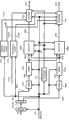
图3是本实施方式中的发送装置300的结构的一例。编码部302A以信息(数据)301A及帧结构信号313为输入,按照帧结构信号313(含有编码部302A在数据的纠错编码中使用的纠错方式、编码率、块长度等信息,使用帧结构信号313所指定的方式。另外,纠错方式也可以切换。),例如进行卷积码、LDPC码及Turbo码等的纠错编码,输出编码后的数据303A。FIG. 3 is an example of the configuration of the transmission device 300 in this embodiment. The
交错器304A以编码后的数据303A及帧结构信号313为输入来进行交错、即顺序的排序,输出交错后的数据305A。(基于帧结构信号313,交错的方法也可以切换。)The
映射部306A以交错后的数据305A及帧结构信号313为输入,进行QPSK(Quadrature Phase Shift Keying)、16QAM(16Quadrature AmplitudeModulation)、64QAM(64Quadrature Amplitude Modulation)等的调制,输出基带信号307A。(基于帧结构信号313,调制方式也可以切换。)The
图19是QPSK调制中的构成基带信号的同相成分I和正交成分Q的IQ平面上的映射方法的一例。例如,如图19(A)所示,在输入数据为“00”的情况下,输出I=1.0、Q=1.0,下面同样地,在输入数据为“01”的情况下,输出I=-1.0、Q=1.0,输出…。图19(B)是和图19(A)不同的QPSK调制的IQ平面上的映射方法的例子,图19(B)和图19(A)的不同之处为,能够通过使图19(A)中的信号点以原点为中心旋转而获得图19(B)的信号点。有关这种星座的旋转方法,在非专利文献9、非专利文献10中示出,另外,也可以应用非专利文献9、非专利文献10中所示的CyclicQ Delay。作为和图19不同的例子,在图20中表示出16QAM时的IQ平面上的信号点配置,与图19(A)对应的例子是图20(A),与图19(B)对应的例子为图20(B)。19 is an example of a mapping method on the IQ plane of the in-phase component I and the quadrature component Q constituting the baseband signal in QPSK modulation. For example, as shown in FIG. 19(A), when the input data is "00", I=1.0 and Q=1.0 are output. Similarly, when the input data is "01", I=- is output. 1.0, Q=1.0, output . . . FIG. 19(B) is an example of the mapping method on the IQ plane of QPSK modulation different from FIG. 19(A). The difference between FIG. 19(B) and FIG. 19(A) is that the ) is rotated around the origin to obtain the signal point in Figure 19(B).
编码部302B以信息(数据)301B及帧结构信号313为输入,按照帧结构信号313(含有使用的纠错方式、编码率、块长度等的信息,使用帧结构信号313所指定的方式。另外,纠错方式也可以切换。),例如进行卷积码、LDPC码、Turbo码等的纠错编码,输出编码后的数据303B。The
交错器304B以编码后的数据303B及帧结构信号313为输入来进行交错、即顺序的排序,输出交错后的数据305B。(基于帧结构信号313,交错的方法也可以切换。)The
映射部306B以交错后的数据305B及帧结构信号313为输入,进行QPSK(Quadrature Phase Shift Keying)、16QAM(16Quadrature AmplitudeModulation)、64QAM(64Quadrature Amplitude Modulation)等的调制,输出基带信号307B。(基于帧结构信号313,调制方式也可以切换。)The
信号处理方法信息生成部314以帧结构信号313为输入,输出与基于帧结构信号313的信号处理方法有关的信息315。还有,与信号处理方法有关的信息315包含指定固定使用哪个预编码矩阵的信息和变更相位的相位变更模式的信息。The signal processing
加权合成部308A以基带信号307A、基带信号307B及与信号处理方法有关的信息315为输入,基于与信号处理方法有关的信息315,对基带信号307A及基带信号307B进行加权合成,输出加权合成后的信号309A。还有,有关加权合成的方法细节,将在后面详细说明。The
无线部310A以加权合成后的信号309A为输入,进行正交调制、频带限制、频率替换及放大等的处理,输出发送信号311A,发送信号311A被从天线312A作为电波输出。
加权合成部308B以基带信号307A、基带信号307B及与信号处理方法有关的信息315为输入,基于与信号处理方法有关的信息315,对基带信号307A及基带信号307B进行加权合成,输出加权合成后的信号316B。The
图21表示加权合成部(308A、308B)的结构。在图21中用虚线围成的区域为加权合成部。基带信号307A和w11相乘而生成w11·s1(t),和w21相乘而生成w21·s1(t)。同样地,基带信号307B和w12相乘而生成w12·s2(t),和w22相乘而生成w22·s2(t)。接下来,获得z1(t)=w11·s1(t)+w12·s2(t)、z2(t)=w21·s1(t)+w22·s2(t)。此时,s1(t)及s2(t)从上述说明可知,成为BPSK(Binary Phase Shift Keying)、QPSK、8PSK(8Phase Shift Keying)、16QAM、32QAM(32Quadrature AmplitudeModulation)、64QAM、256QAM、16APSK(16Amplitude Phase Shift Keying)等调制方式的基带信号。FIG. 21 shows the configuration of the weighted combination unit ( 308A, 308B). The area enclosed by the dotted line in FIG. 21 is a weighted synthesis unit. The
这里,两个加权合成部使用固定的预编码矩阵来执行加权,作为预编码矩阵,作为一例有基于下式(37)或式(38)的条件而使用式(36)的方法。但这只是一例,α的值并不限于式(37)、式(38),也可以设为别的值,例如将α设为1。Here, the two weighting combining units perform weighting using a fixed precoding matrix, and as an example of the precoding matrix, there is a method of using Expression (36) based on the condition of the following Expression (37) or Expression (38). However, this is just an example, and the value of α is not limited to Expression (37) and Expression (38), and may be set to another value, for example, α is set to 1.
还有,预编码矩阵为Also, the precoding matrix is
[数式36][Formula 36]
其中,在上述式(36)中,α为where, in the above formula (36), α is
[数式37][Formula 37]
或者,在上述式(36)中,α为Alternatively, in the above equation (36), α is
[数式38][Formula 38]
还有,预编码矩阵并不限于式(36),也可以使用式(39)所示的预编码矩阵。Also, the precoding matrix is not limited to Equation (36), and the precoding matrix shown in Equation (39) may also be used.
[数式39][Formula 39]
在该式(39)中,只要以a=Aejδ11、b=Bejδ12、c=Cejδ21、d=Dejδ22来表达即可。另外,a、b、c、d的任一个也可以是“零”。例如,也可以是(1)a为零,b、c、d不为零,(2)b为零,a、c、d不为零,(3)c为零,a、b、d不为零,(4)d为零,a、b、c不为零这样的结构。In this formula (39), what is necessary is just to express it as a=Aejδ11 , b=Bejδ12 , c=Cejδ21 , and d=Dejδ22 . In addition, any one of a, b, c, and d may be "zero". For example, (1) a is zero, b, c, d are not zero, (2) b is zero, a, c, d are not zero, (3) c is zero, a, b, d are not is zero, (4) d is zero, and a, b, c are not zero.
还有,变更了调制方式、纠错码及其编码率的某一个时,也可以对使用的预编码矩阵进行设定及变更,并且固定地使用该预编码矩阵。Also, when any one of the modulation scheme, error correction code, and coding rate is changed, the precoding matrix to be used may be set and changed, and the precoding matrix may be used fixedly.
相位变更部317B以加权合成后的信号316B及与信号处理方法有关的信息315为输入,规则地变更该信号316B的相位并输出。所谓规则地变更指的是,在预定的周期(例如每n个码元(n为1以上的整数)或者每一预定的时间)内,按照预定的相位变更模式来变更相位。有关相位变更模式的细节,将在下述实施方式4中进行说明。The
无线部310B以相位变更后的信号309B为输入,实施正交调制、频带限制、频率替换及放大等的处理,输出发送信号311B,发送信号311B被从天线312B作为电波输出。
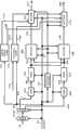
图4表示和图3不同的发送装置400的结构例。在图4中,说明和图3不同的部分。FIG. 4 shows a configuration example of a transmission device 400 different from that in FIG. 3 . In FIG. 4, parts different from those in FIG. 3 are explained.
编码部402以信息(数据)401及帧结构信号313为输入,基于帧结构信号313进行纠错编码,输出编码后的数据402。The
分配部404以编码后的数据403为输入,分配并输出数据405A及数据405B。还有,在图4中,记述了编码部为一个的情况,但不限于此,针对将编码部设为m(m为1以上的整数),并由分配部将由各编码部制作的编码数据分为2个系统的数据来输出的情况,本发明也可以同样地实施。
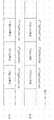
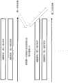
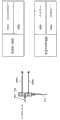
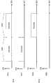
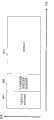
图5表示本实施方式中的发送装置的时间轴上的帧结构一例。码元500_1是用于向接收装置通知发送方法的码元,例如,传输用于传输数据码元的纠错方式、其编码率的信息以及用于传输数据码元的调制方式的信息等。FIG. 5 shows an example of the frame structure on the time axis of the transmission device in this embodiment. Symbol 500_1 is a symbol for notifying a receiving apparatus of a transmission method, for example, information on an error correction method used to transmit a data symbol, its coding rate, and information on a modulation method used to transmit a data symbol.
码元501_1是用于推定发送装置所发送的调制信号z1(t){其中t为时间}的信道变动的码元。码元502_1是调制信号z1(t)向(时间轴上的)码元编号u发送的数据码元,码元503_1是调制信号z1(t)向码元编号u+1发送的数据码元。The symbol 501_1 is a symbol for estimating the channel variation of the modulated signal z1(t) {where t is time} transmitted by the transmitting device. Symbol 502_1 is a data symbol transmitted by modulated signal z1(t) to symbol number u (on the time axis), and symbol 503_1 is a data symbol transmitted by modulated signal z1(t) to symbol
码元501_2是用于推定发送装置所发送的调制信号z2(t){其中,t为小时}的信道变动的码元。码元502_2是调制信号z2(t)向码元编号u发送的数据码元,码元503_2是调制信号z2(t)向码元编号u+1发送的数据码元。The symbol 501_2 is a symbol for estimating the channel variation of the modulated signal z2(t) {where t is hours} transmitted by the transmitting device. The symbol 502_2 is the data symbol sent by the modulated signal z2(t) to the symbol number u, and the symbol 503_2 is the data symbol sent by the modulated signal z2(t) to the symbol
此时,在z1(t)内的码元和z2(t)内的码元中,同一时刻(同一时间)的码元使用同一(共同)频率,从发送天线发送。At this time, among the symbols in z1(t) and the symbols in z2(t), symbols at the same time (same time) are transmitted from the transmission antenna using the same (common) frequency.
说明发送装置发送的调制信号z1(t)和调制信号z2(t)以及接收装置中的接收信号r1(t)、r2(t)的关系。The relationship between the modulated signal z1(t) and the modulated signal z2(t) transmitted by the transmitting device and the received signals r1(t) and r2(t) in the receiving device will be described.
在图5中,504#1、504#2表示发送装置中的发送天线,505#1、505#2表示接收装置中的接收天线,发送装置分别从发送天线504#1和发送天线504#2发送调制信号z1(t)和调制信号z2(t)。此时,调制信号z1(t)及调制信号z2(t)占用同一(共同的)频率(频带)。假设发送装置的各发送天线和接收装置的各接收天线的信道变动分别为h11(t)、h12(t)、h21(t)、h22(t),接收装置的接收天线505#1接收到的接收信号为r1(t),接收装置的接收天线505#2接收到的接收信号为r2(t),则下面的关系式成立。In Fig. 5, 504#1, 504#2 represent the transmitting antenna in the transmitting device, 505#1, 505#2 represent the receiving antenna in the receiving device, and the transmitting device receives from the transmitting
[数式40][Formula 40]
图6是与本实施方式中的加权方法(预编码(Precoding)方法)及相位变更方法相关的图,加权合成部600是整合了图3的加权合成部308A和308B双方后的加权合成部。如图6所示,流s1(t)及流s2(t)对应于图3的基带信号307A及307B,也就是说,成为依据QPSK、16QAM、64QAM等调制方式的映射的、基带信号的同相I成分和正交Q成分。而且,如同图6的帧结构那样,流s1(t)将码元编号u的信号表达为s1(u),将码元编号u+1的信号表达为s1(u+1),…。同样,流s2(t)将码元编号u的信号表达为s2(u),将码元编号u+1的信号表达为s2(u+1),…。而且,加权合成部600以图3中的基带信号307A(s1(t))及307B(s2(t))及与信号处理方法有关的信息315为输入,实施依据与信号处理方法有关的信息315的加权,输出图3的加权合成后的信号309A(z1(t))、316B(z2'(t))。相位变更部317B变更加权后的信号316B(z2'(t))的相位,输出相位变更后的信号309B(z2(t))。FIG. 6 is a diagram related to a weighting method (precoding method) and a phase changing method in this embodiment. The
此时,若假设固定的预编码矩阵F中的第1行的矢量为W1=(w11,w12),则z1(t)可以用下式(41)来表达。At this time, assuming that the vector of the first row in the fixed precoding matrix F is W1=(w11, w12), then z1(t) can be expressed by the following formula (41).
[数式41][Formula 41]
z1(t)=W1×(s1(t),s2(t))T…式(41)z1(t)=W1×(s1(t), s2(t))T ... Formula (41)
另一方面,若假设固定的预编码矩阵F中的第2行的矢量为W2=(w21,w22),且由相位变更部得到的相位变更式为y(t),则z2(t)可以用下式(42)来表达。On the other hand, assuming that the vector of the second row in the fixed precoding matrix F is W2=(w21, w22), and the phase changing formula obtained by the phase changing part is y(t), then z2(t) can be It is expressed by the following formula (42).
[数式42][Formula 42]
z2(t)=y(t)×W2×(s1(t),s2(t))T…式(42)z2(t) = y(t) × W2 × (s1(t), s2(t))T ... Formula (42)
这里,y(t)是用于按照预定的方式来变更相位的公式,若设周期为4,则时刻u的相位变更式例如可以用式(43)来表达。Here, y(t) is an expression for changing the phase in a predetermined manner, and if the period is set to 4, the phase changing expression at time u can be expressed by, for example, Equation (43).
[数式43][Formula 43]
y(u)=ej0…式(43)y(u)=ej0 ...Formula (43)
同样,时刻u+1的相位变更式例如可以用式(44)来表达。Similarly, the phase change equation at time u+1 can be expressed by, for example, Equation (44).
[数式44][Formula 44]
也就是说,时刻u+k的相位变更式可以用式(45)来表达。That is to say, the phase change formula at time u+k can be expressed by formula (45).
[数式45][Formula 45]
还有,式(43)~(45)所示的规则的相位变更例只是一例。In addition, the regular phase changing examples shown in the formulas (43) to (45) are just examples.
规则的相位变更的周期并不限于4。如果该周期的个数变多,则能够促进接收装置的接收性能(更加正确而言是纠错性能)提高该个数量(并不是说只要周期大就好,而是避开2那样小的值更好的可能性较高。)。The period of regular phase change is not limited to 4. If the number of cycles is increased, the receiving performance of the receiving device (more precisely, the error correction performance) can be improved to increase the number (not to say that as long as the cycle is large, but to avoid a value as small as 2 Better is more likely.).
另外,在由上式(43)~(45)所示的相位变更例中,示出了使其依次旋转规定的相位量(在上述式中分别为π/2)的结构,但也可以不使其旋转相同的相位量,而随机地变更相位。例如,y(t)也可以按照预定的周期,按式(46)或式(47)所示的顺序来变更相乘的相位。在相位的规则性变更中重要的是,规则地变更调制信号的相位,对于变更的相位的程度,优选为尽量均等,例如对-π弧度到π弧度,优选为均匀分布,但也可以是随机的。In addition, in the phase change examples shown by the above formulas (43) to (45), the configurations are shown in which the phases are sequentially rotated by predetermined phase amounts (in the above formulas, respectively, π/2), but it is not necessary to Make it rotate by the same amount of phase, but change the phase randomly. For example, y(t) may change the phase of multiplication in accordance with the order shown in Equation (46) or Equation (47) at a predetermined cycle. In the regular change of the phase, it is important to change the phase of the modulation signal regularly. For the degree of the changed phase, it is preferably as uniform as possible, for example, it is preferably uniformly distributed from -π radians to π radians, but it can also be random of.
[数式46][Formula 46]
[数式47][Formula 47]
这样,图6的加权合成部600使用预定的固定的预编码权重来执行预编码,相位变更部317B一边规则地改变其变更程度,一边变更所输入的信号的相位。In this way, the weighted combining
在LOS环境下,若使用特殊的预编码矩阵,则存在接收品质得到较大改善的可能性,但是根据直接波的状况,该特殊的预编码矩阵因接收时的直接波的相位、振幅成分而不同。但是,在LOS环境下存在某种规则,若按照该规则来规则地变更发送信号的相位,则数据的接收品质较大改善。本发明提出了改善LOS环境的信号处理方法。In the LOS environment, if a special precoding matrix is used, there is a possibility that the reception quality will be greatly improved. However, depending on the situation of the direct wave, the special precoding matrix may be affected by the phase and amplitude components of the direct wave at the time of reception. different. However, there is a certain rule in the LOS environment, and if the phase of the transmission signal is regularly changed according to the rule, the reception quality of data will be greatly improved. The present invention proposes a signal processing method to improve the LOS environment.
图7表示本实施方式中接收装置700的结构的一例。无线部703_X以由天线701_X接收到的接收信号702_X为输入,实施频率替换及正交解调等处理,输出基带信号704_X。FIG. 7 shows an example of the configuration of a receiving device 700 in this embodiment. The wireless unit 703_X takes the reception signal 702_X received by the antenna 701_X as input, performs frequency replacement, quadrature demodulation, and other processing, and outputs a baseband signal 704_X.
由发送装置发送的调制信号z1中的信道变动推定部705_1以基带信号704_X为输入,提取图5中的信道推定用的参考码元501_1,推定与式(40)的h11对应的值,输出信道推定信号706_1。The channel variation estimation unit 705_1 in the modulated signal z1 transmitted by the transmitting device takes the baseband signal 704_X as input, extracts the reference symbol 501_1 for channel estimation in FIG. 5 , estimates a value corresponding to h11 in equation (40), and outputs the channel Estimate signal 706_1.
由发送装置发送的调制信号z2中的信道变动推定部705_2以基带信号704_X为输入,提取图5中的信道推定用的参考码元501_2,推定与式(40)的h12对应的值,输出信道推定信号706_2。The channel variation estimation unit 705_2 in the modulated signal z2 transmitted by the transmitting device takes the baseband signal 704_X as input, extracts the reference symbol 501_2 for channel estimation in FIG. Estimate signal 706_2.
无线部703_Y以由天线701_Y接收到的接收信号702_Y为输入,实施频率替换及正交解调等处理,输出基带信号704_Y。The wireless unit 703_Y receives the reception signal 702_Y received by the antenna 701_Y as input, performs processing such as frequency replacement and quadrature demodulation, and outputs a baseband signal 704_Y.
由发送装置发送的调制信号z1中的信道变动推定部707_1以基带信号704_Y为输入,提取图5中的信道推定用的参考码元501_1,推定与式(40)的h21对应的值,输出信道推定信号708_1。The channel variation estimation unit 707_1 in the modulated signal z1 transmitted by the transmitting device takes the baseband signal 704_Y as input, extracts the reference symbol 501_1 for channel estimation in FIG. Estimate signal 708_1.
由发送装置发送的调制信号z2中的信道变动推定部707_2以基带信号704_Y为输入,提取图5中的信道推定用的参考码元501_2,推定与式(40)的h22对应的值,输出信道推定信号708_2。The channel variation estimation unit 707_2 in the modulated signal z2 transmitted by the transmitting device takes the baseband signal 704_Y as input, extracts the reference symbol 501_2 for channel estimation in FIG. Estimate signal 708_2.
控制信息解码部709以基带信号704_X及704_Y为输入,检测用于通知图5的发送方法的码元500_1,输出与发送装置所通知的发送方法的信息有关的信号710。Control
信号处理部711以基带信号704_X、704_Y、信道推定信号706_1、706_2、708_1、708_2及与发送装置所通知的发送方法的信息有关的信号710为输入,进行检波及解码,输出接收数据712_1及712_2。The
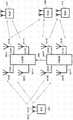
接下来,详细说明图7的信号处理部711的动作。图8表示本实施方式中的信号处理部711的结构的一例。图8主要包括INNER MIMO检波部、软入软出解码器及系数生成部。有关该结构中的反复解码的方法,已经在非专利文献2、非专利文献3中详细记载,但是非专利文献2、非专利文献3中所述的MIMO传输方式是空间复用MIMO传输方式,而本实施方式中的传输方式和非专利文献2、非专利文献3的不同之处为,是一种随着时间而规则地变更信号的相位,并且使用预编码矩阵的MIMO传输方式。若设公式(36)中的(信道)矩阵为H(t),图6中的预编码权重矩阵为F(这里预编码矩阵是在1个接收信号中不变更的固定的矩阵),由图6的相位变更部得到的相位变更式的矩阵为Y(t)(这里Y(t)随着t而变化),接收矢量为R(t)=(r1(t),r2(t))T,流矢量S(t)=(s1(t),s2(t))T,则下面的关系式成立。Next, the operation of the
[数式48][Formula 48]
R(t)=H(t)×Y(t)×F×S(t)…式(48)R(t)=H(t)×Y(t)×F×S(t)…Formula (48)
此时,接收装置可以通过取得H(t)×Y(t)×F,对接收矢量R(t)应用非专利文献2、非专利文献3的解码方法。At this time, the reception device can apply the decoding methods of
因此,图8的系数生成部819以与发送装置所通知的发送方法的信息(用于确定所使用的固定的预编码矩阵及变更了相位时的相位变更模式的信息)有关的信号818(对应于图7的710)为输入,输出与信号处理方法的信息有关的信号820。Therefore, the
INNER MIMO检波部803以与信号处理方法的信息有关的信号820为输入,通过利用该信号,并利用式(48)的关系,进行反复检波·解码,以下说明其动作。The INNER
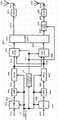
在图8所示的结构的信号处理部中,为了进行反复解码(反复检波),需要进行图10所示的处理方法。首先,进行调制信号(流)s1的1码字(或者1帧)及调制信号(流)s2的1码字(或者1帧)的解码。其结果,从软入软出解码器获得调制信号(流)s1的1码字(或者1帧)及调制信号(流)s2的1码字(或者1帧)的各比特的对数似然比(LLR:Log-LikelihoodRatio)。然后,使用该LLR再次进行检波·解码。多次进行该操作(将该操作称为反复解码(反复检波)。)。以后,重点说明以1帧中的特定时间的码元的对数似然比(LLR)的制作方法。In the signal processing unit having the configuration shown in FIG. 8 , in order to perform iterative decoding (iterative detection), it is necessary to perform the processing method shown in FIG. 10 . First, one codeword (or one frame) of the modulated signal (stream) s1 and one codeword (or one frame) of the modulated signal (stream) s2 are decoded. As a result, the log likelihood of each bit of 1 codeword (or 1 frame) of the modulated signal (stream) s1 and 1 codeword (or 1 frame) of the modulated signal (stream) s2 is obtained from the soft-in soft-out decoder Ratio (LLR: Log-LikelihoodRatio). Then, detection and decoding are performed again using this LLR. This operation is performed a plurality of times (this operation is called iterative decoding (iterative detection).). Hereinafter, the method of creating the log-likelihood ratio (LLR) of symbols at a specific time in one frame will be mainly described.
在图8中,存储部815以基带信号801X(对应于图7的基带信号704_X。)、信道推定信号群802X(对应于图7的信道推定信号706_1、706_2。)、基带信号801Y(对应于图7的基带信号704_Y。)及信道推定信号群802Y(对应于图7的信道推定信号708_1、708_2。)为输入,为了实现反复解码(反复检波),执行(计算)式(48)中的H(t)×Y(t)×F,作为变形信道信号群而存储计算出的矩阵。然后,存储部815在需要时输出上述信号,来作为基带信号816X、变形信道推定信号群817X及基带信号816Y、变形信道推定信号群817Y。In FIG. 8 ,
有关其后的动作,将分为初始检波的情形和反复解码(反复检波)的情况进行说明。The subsequent operation will be described separately for the case of initial detection and the case of iterative decoding (repeated detection).
<初始检波的情形><Initial detection situation>
INNER MIMO检波部803以基带信号801X、信道推定信号群802X、基带信号801Y及信道推定信号群802Y为输入。在此,将调制信号(流)s1、调制信号(流)s2的调制方式作为16QAM来说明。The INNER
INNER MIMO检波部803首先根据信道推定信号群802X及信道推定信号群802Y,执行H(t)×Y(t)×F,求取与基带信号801X对应的候选信号点。图11表示此时的状况。在图11中,●(黑点)是IQ平面上的候选信号点,由于调制方式为16QAM,所以候选信号点存在256个。(但是,在图11中示出示意图,所以未示出全部256个候选信号点。)这里,若设由调制信号s1传输的4比特为b0、b1、b2、b3,由调制信号s2传输的4比特为b4、b5、b6、b7,则在图11中存在与(b0,b1,b2,b3,b4,b5,b6,b7)对应的候选信号点。然后,求取接收信号点1101(对应于基带信号801X。)和候选信号点各自之间的平方欧氏距离。然后,用噪声的方差σ2除以各个平方欧氏距离。因此,求出EX(b0,b1,b2,b3,b4,b5,b6,b7),该EX(b0,b1,b2,b3,b4,b5,b6,b7)是将与(b0,b1,b2,b3,b4,b5,b6,b7)对应的候选信号点和接收信号点平方欧氏距离除以噪声的方差后的值。还有,各基带信号、调制信号s1、s2是复信号。The INNER
同样地,根据信道推定信号群802X及信道推定信号群802Y,执行H(t)×Y(t)×F,求取与基带信号801Y对应的候选信号点,并求取和接收信号点(对应于基带信号801Y。)之间的平方欧氏距离,将该平方欧氏距离除以噪声的方差σ2。因此,求出EY(b0,b1,b2,b3,b4,b5,b6,b7),该EY(b0,b1,b2,b3,b4,b5,b6,b7)是将与(b0,b1,b2,b3,b4,b5,b6,b7)对应的候选信号点和接收信号点平方欧氏距离除以噪声的方差后的值。Similarly, according to the channel
然后,求取EX(b0,b1,b2,b3,b4,b5,b6,b7)+EY(b0,b1,b2,b3,b4,b5,b6,b7)=E(b0,b1,b2,b3,b4,b5,b6,b7)。Then, calculate EX (b0, b1, b2, b3, b4, b5, b6, b7) + EY (b0, b1, b2, b3, b4, b5, b6, b7) = E (b0, b1, b2, b3, b4, b5, b6, b7).
INNER MIMO检波部803作为信号804而输出E(b0,b1,b2,b3,b4,b5,b6,b7)。The INNER
对数似然计算部805A以信号804为输入,计算比特b0、b1、b2及b3的对数似然(log likelihood),输出对数似然信号806A。但是,在对数似然的计算中,计算“1”时的对数似然及“0”时的对数似然。其计算方法如式(28)、式(29)及式(30)所示,详细情况记载于非专利文献2、非专利文献3中。The log
同样地,对数似然计算部805B以信号804为输入,计算比特b4、b5、b6及b7的对数似然,输出对数似然信号806B。Similarly, the log-
解交错器(807A)以对数似然信号806A为输入,进行与交错器(图3的交错器(304A))对应的解交错,输出解交错后的对数似然信号808A。The deinterleaver (807A) receives the
同样地,解交错器(807B)以对数似然信号806B为输入,进行与交错器(图3的交错器(304B))对应的解交错,输出解交错后的对数似然信号808B。Similarly, the deinterleaver (807B) receives the
对数似然比计算部809A以解交错后的对数似然信号808A为输入,计算由图3的编码器302A编码后的比特的对数似然比(LLR:Log-LikelihoodRatio),输出对数似然比信号810A。The log-likelihood
同样,对数似然比计算部809B以解交错后的对数似然信号808B为输入,计算由图3的编码器302B编码后的比特的对数似然比(LLR:Log-Likelihood Ratio),输出对数似然比信号810B。Similarly, the log-likelihood ratio calculation unit 809B takes the deinterleaved log-
软入软出解码器811A以对数似然比信号810A为输入来进行解码,输出解码后的对数似然比812A。The soft-in soft-out decoder 811A takes the log-
同样,软入软出解码器811B以对数似然比信号810B为输入来进行解码,输出解码后的对数似然比812B。Similarly, the soft-in soft-out decoder 811B takes the log-likelihood ratio signal 810B as input to decode, and outputs the decoded log-likelihood ratio 812B.
<反复解码(反复检波)的情况,反复次数k><In the case of repeated decoding (repeated detection), the number of repetitions k>
交错器(813A)以第k-1次的由软入软出解码器得到的解码后的对数似然比812A为输入来进行交错,输出交错后的对数似然比814A。此时,交错器(813A)的交错模式和图3的交错器(304A)的交错模式相同。The interleaver (813A) performs interleaving by taking the decoded log likelihood ratio 812A obtained by the soft-in/soft-out decoder of the k-1th time as input, and outputs an interleaved
交错器(813B)以第k-1次的由软入软出解码器得到的解码后的对数似然比812B为输入来进行交错,输出交错后的对数似然比814B。此时,交错器(813B)的交错模式和图3和交错器(304B)的交错模式相同。The interleaver ( 813B ) performs interleaving by taking the decoded log likelihood ratio 812B obtained by the soft-in soft-out decoder of the k-1th time as input, and outputs the interleaved
INNER MIMO检波部803以基带信号816X、变形信道推定信号群817X、基带信号816Y、变形信道推定信号群817Y、交错后的对数似然比814A及交错后的对数似然比814B为输入。这里,不使用基带信号801X、信道推定信号群802X、基带信号801Y及信道推定信号群802Y,而使用基带信号816X、变形信道推定信号群817X、基带号816Y及变形信道推定信号群817Y,这是因为,由于反复解码而产生了延迟时间。The INNER
INNER MIMO检波部803反复解码时的动作和初始检波时的动作的不同之处为,在信号处理时使用了交错后的对数似然比814A及交错后的对数似然比814B。INNER MIMO检波部803首先和初始检波时同样地求取E(b0,b1,b2,b3,b4,b5,b6,b7)。除此之外,还根据交错后的对数似然比814A及交错后的对数似然比814B求取与式(11)、式(32)对应的系数。然后,利用该求出的系数来修正E(b0,b1,b2,b3,b4,b5,b6,b7)的值,将其值设为E'(b0,b1,b2,b3,b4,b5,b6,b7),作为信号804而输出。The difference between the operation of the INNER
对数似然计算部805A以信号804为输入,计算比特b0、b1、b2及b3的对数似然(log likelihood),输出对数似然信号806A。其中,在对数似然的计算中,计算“1”时的对数似然及“0”时的对数似然。其计算方法如式(31)、式(32)、式(33)、式(34)及式(35)所示,并且记载在非专利文献2、非专利文献3中。The log
同样地,对数似然计算部805B以信号804为输入,计算比特b4、b5、b6及b7的对数似然,输出对数似然信号806B。解交错器此后的动作和初始检波相同。Similarly, the log-
还有,在图8中示出了进行反复检波时的信号处理部的结构,但是反复检波在获得良好的接收品质的方面并不是必须的结构,也可以仅有反复检波所需的结构部分,而没有交错器813A、813B的结构。此时,INNER MIMO检波部803不进行反复的检波。In addition, in FIG. 8, the structure of the signal processing part at the time of performing iterative detection is shown, but iterative detection is not an essential structure in order to obtain a good reception quality, You may only have the structural part necessary for iterative detection, However, there is no
而且,在本实施方式中重要的部分是,进行H(t)×Y(t)×F的运算。还有,如非专利文献5等所示,也可以使用QR分解来进行初始检波及反复检波。Furthermore, an important part in this embodiment is to perform calculation of H(t)×Y(t)×F. Also, as shown in
另外,如非专利文献11所示,也可以根据H(t)×Y(t)×F,进行MMSE(Minimum Mean Square Error)、ZF(Zero Forcing)的线性运算,进行初始检波。In addition, as shown in
图9是和图8不同的信号处理部的结构,是图4的发送装置所发送的调制信号所需的信号处理部。和图8的不同之处为软入软出解码器的个数,软入软出解码器901以对数似然比信号810A、810B为输入,进行解码,输出解码后的对数似然比902。分配部903以解码后的对数似然比902为输入,进行分配。其以外的部分是和图8相同的动作。FIG. 9 is a configuration of a signal processing unit different from that in FIG. 8, and is a signal processing unit required for a modulated signal transmitted by the transmitting device in FIG. 4. FIG. The difference from FIG. 8 is the number of soft-in soft-out decoders. The soft-in soft-
如上,如本实施方式那样,当MIMO传输系统的发送装置从多根天线发送多个调制信号时,将预编码矩阵相乘,并且随着时间变更相位,规则地进行该相位的变更,由此,在直接波占主导的LOS环境下,与使用以往的空间复用MIMO传输时相比,可以获得提高接收装置中的数据的接收品质的效果。As described above, when transmitting a plurality of modulated signals from multiple antennas, the transmitting device of the MIMO transmission system multiplies the precoding matrix and changes the phase over time, and the phase is changed regularly, thereby , in a LOS environment where direct waves dominate, compared with conventional spatial multiplexing MIMO transmission, an effect of improving the reception quality of data in a receiving device can be obtained.
在本实施方式中,特别是针对接收装置的结构,限定天线数而说明了其动作,但是增加天线数也可以同样地实施。也就是说,接收装置中的天线数并不给本实施方式的动作、效果带来影响。In the present embodiment, the operation of the receiving device is described while limiting the number of antennas, especially for the configuration of the receiving device, but the same implementation can be performed by increasing the number of antennas. That is, the number of antennas in the receiving device does not affect the operation and effect of this embodiment.
另外,在本实施方式中,特别是以LDPC码为例进行了说明,但是并不限于此,另外,有关解码方法,作为软入软出解码器也不限于和乘积解码,还有其他的软入软出的解码方法,例如BCJR算法、SOVA算法及Max-log-MAP算法等。详细情况记载在非专利文献6中。In addition, in this embodiment, the LDPC code is particularly used as an example for description, but it is not limited to this. In addition, regarding the decoding method, the soft-in soft-out decoder is not limited to sum product decoding, and there are other soft codes. In and soft out decoding methods, such as BCJR algorithm, SOVA algorithm and Max-log-MAP algorithm, etc. The details are described in
另外,在本实施方式中,以单载波方式为例进行了说明,但是并不限于此,在实施了多载波传输的情况下也能够同样地实施。因此,例如在采用扩频通信方式、OFDM(Orthogonal Frequency-Division Multiplexing)方式、SC-FDMA(Single Carrier Frequency Division Multiple Access)、SC-OFDM(Single Carrier Orthogonal Frequency-Division Multiplexing)方式及非专利文献7等中所示的子波OFDM方式等的情况下,也能够同样地实施。另外,在本实施方式中,数据码元以外的码元、例如导频码元(导言、独特字等)及控制信息传输用的码元等在帧中可以任意配置。In addition, in the present embodiment, the single-carrier method has been described as an example, but the present invention is not limited to this, and it can also be implemented in the same manner when multi-carrier transmission is performed. Therefore, for example, in the use of spread spectrum communication methods, OFDM (Orthogonal Frequency-Division Multiplexing) methods, SC-FDMA (Single Carrier Frequency Division Multiple Access), SC-OFDM (Single Carrier Orthogonal Frequency-Division Multiplexing) methods and
下面,作为多载波方式的一例,说明采用OFDM方式时的例子。Next, as an example of the multi-carrier method, an example when the OFDM method is adopted will be described.
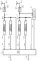
图12表示采用OFDM方式时的发送装置的结构。在图12中,对于和图3同样地动作的部分,赋予相同的符号。FIG. 12 shows the configuration of a transmission device when the OFDM method is used. In FIG. 12 , the parts that operate in the same manner as those in FIG. 3 are assigned the same symbols.
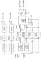
OFDM方式相关处理部1201A以加权后的信号309A为输入,实施OFDM方式相关的处理,输出发送信号1202A。同样地,OFDM方式相关处理部1201B以相位变更后的信号309B为输入,输出发送信号1202B。The OFDM scheme-related
图13表示图12的OFDM方式相关处理部1201A、1201B以后的结构的一例,与图12的1201A到312A相关的部分是1301A到1310A,与1201B到312B相关的部分是1301B到1310B。FIG. 13 shows an example of the configuration of the OFDM system-related
串并行替换部1302A对加权后的信号1301A(对应于图12的加权后的信号309A)进行串并行替换,输出并行信号1303A。The serial-to-
排序部1304A以并行信号1303A为输入,进行排序,输出排序后的信号1305A。还有,有关排序将在后面详细说明。Sorting
逆快速傅立叶替换部1306A以排序后的信号1305A为输入,实施逆快速傅立叶替换,输出逆傅立叶替换后的信号1307A。The inverse fast
无线部1308A以逆傅立叶替换后的信号1307A为输入,执行频率替换及放大等的处理,输出调制信号1309A,调制信号1309A被从天线1310A作为电波输出。
串并行替换部1302B对于加权并且变更相位后的信号1301B(对应于图12的相位变更后的信号309B)进行串并行替换,输出并行信号1303B。The serial-to-
排序部1304B以并行信号1303B为输入,进行排序,输出排序后的信号1305B。还有,有关排序将在后面详细说明。Sorting
逆快速傅立叶替换部1306B以排序后的信号1305B为输入,实施逆快速傅立叶替换,输出逆傅立叶替换后的信号1307B。The inverse fast
无线部1308B以逆傅立叶替换后的信号1307B为输入,执行频率替换及放大等的处理,输出调制信号1309B,调制信号1309B被从天线1310B作为电波输出。
在图3的发送装置中,因为不是采用多载波的传输方式,所以像图6那样,以成为4周期的方式来变更相位,沿时间轴方向配置了相位变更后的码元。在图12所示的采用OFDM方式的多载波传输方式的情况下,当然可以想到如图3那样进行预编码,沿时间轴方向配置变更相位后的码元,在每个(子)载波中进行上述处理的方式,而在多载波传输方式的情况下,可以想到利用频率轴方向或者频率轴·时间轴双方来进行配置的方法。在下面,对于这一点进行说明。In the transmitting apparatus in FIG. 3, since the multi-carrier transmission method is not used, the phase is changed so as to be 4 cycles as shown in FIG. 6, and the phase-changed symbols are arranged along the time axis direction. In the case of multi-carrier transmission using OFDM as shown in Figure 12, it is of course conceivable to perform precoding as shown in Figure 3, arrange symbols with changed phases along the time axis, and perform precoding on each (sub)carrier In the case of the above-mentioned processing method, in the case of the multi-carrier transmission method, it is conceivable to use the frequency axis direction or both the frequency axis and the time axis to arrange the method. This point will be described below.
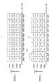
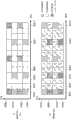
图14表示横轴频率、纵轴时间上的图13的排序部1301A、1301B中的码元的排序方法的一例,频率轴由(子)载波0~(子)载波9构成,调制信号z1和z2在同一时刻(时间)使用同一频带,图14(A)表示调制信号z1的码元的排序方法,图14(B)表示调制信号z2的码元的排序方法。串并行替换部1302A对于作为输入的加权后的信号1301A的码元,按顺序编号为#0、#1、#2、#3、…。在此,由于考虑了周期为4的情形,因而#0、#1、#2、#3成为一周期量。同样地考虑,#4n、#4N+1、#4n+2、#4n+3(n为0以上的整数)成为一周期量。FIG. 14 shows an example of the sorting method of symbols in the
此时,如图14(a)那样,规则地配置为,从载波0开始按顺序配置码元#0、#1、#2、#3、…,并在时刻$1配置码元#0~#9,然后,在时刻$2配置码元#10~#19。还有,调制信号z1和z2是复信号。At this time, as shown in FIG. 14(a), it is regularly arranged such that
同样,串并行替换部1302B对于作为输入的加权并且变更相位后的信号1301B的码元,按顺序编号为#0、#1、#2、#3、…。在此,由于考虑了周期为4的情形,因而#0、#1、#2、#3分别进行不同的相位变更,#0、#1、#2、#3成为一周期量。若同样地考虑,则#4n、#4N+1、#4n+2、#4n+3(n为0以上的整数)分别进行不同的相位变更,#4n、#4N+1、#4n+2、#4n+3成为一周期量。Similarly, the serial-to-
此时,象图14(b)那样,规则地配置为,从载波0开始按顺序配置码元#0、#1、#2、#3、…,并在时刻$1配置码元#0~#9,然后,在时刻$2配置码元#10~#19。At this time, as shown in Fig. 14(b), it is regularly arranged that
而且,图14(B)所示的码元群1402是使用图6所示的相位变更方法时的1周期量的码元,码元#0是使用图6的时刻u的相位时的码元,码元#1是使用图6的时刻u+1的相位时的码元,码元#2是使用图6的时刻u+2的相位时的码元,码元#3是使用图6的时刻u+3的相位时的码元。因此,在码元#x中,x mod4为0(用4除以x时的余数,因此,mod:modulo)时,码元#x是使用图6飞时刻u的相位时的码元,x mod4为1时,码元#x是使用图6飞时刻u+1的相位时的码元,x mod4为2时,码元#x是使用图6飞时刻u+2的相位时的码元,x mod4为3时,码元#x是使用图6飞时刻u+3的相位时的码元。Furthermore, the
还有,在本实施方式中,图14(A)所示的调制信号z1未变更相位。In addition, in the present embodiment, the phase of the modulation signal z1 shown in FIG. 14(A) is not changed.
这样,在采用OFDM方式等的多载波传输方式的情况下,和单载波传输时不同,具有能够沿频率轴方向排列码元的特征。而且,码元的排列方法不限于图14的排列方法。对于其他的例子,使用图15、图16进行说明。In this way, when using a multi-carrier transmission method such as the OFDM method, unlike the case of single-carrier transmission, it has a feature that symbols can be arranged in the direction of the frequency axis. Also, the arrangement method of symbols is not limited to the arrangement method shown in FIG. 14 . Other examples will be described using FIGS. 15 and 16 .
图15表示和图14不同的横轴频率、纵轴时间上的图13的排序部1301A、1301B中的码元的排序方法的一例,图15(A)表示调制信号z1的码元的排序方法,图15(B)表示调制信号z2的码元的排序方法。图15(A)(B)和图14的不同之处为,调制信号z1的码元的排序方法与调制信号z2的码元的排序方法不同,在图15(B)中,将码元#0~#5配置于载波4~载波9中,将码元#6~#9配置于载波0~3中,随后,以同样的规则,将码元#10~#19配置于各载波中。此时,和图14(B)相同,图15(B)所示的码元群1502是使用图6所示的相位变更方法时的1周期量的码元。FIG. 15 shows an example of the sorting method of symbols in the
图16表示和图14不同的横轴频率、纵轴时间上的图13的排序部1301A、1301B中的码元的排序方法的一例,图16(A)表示调制信号z1的码元的排序方法,图16(B)表示调制信号z2的码元的排序方法。图16(A)(B)和图14的不同之处为,在图14中,将码元依次配置到载波中,而在图16中,未将码元依次配置到载波中。当然,在图16中,也可以与图15同样地,使调制信号z1的码元的排序方法和调制信号z2的排序方法不同。FIG. 16 shows an example of the sorting method of the symbols in the
图17表示和图14~16不同的横轴频率、纵轴时间上的图13的排序部1301A、1301B中的码元的排序方法的一例,图17(A)表示调制信号z1的码元的排序方法,图17(B)表示调制信号z2的码元的排序方法。在图14~16中,将码元沿频率轴方向进行排列,而在图17中利用频率、时间轴的双方来配置码元。FIG. 17 shows an example of the sorting method of symbols in the
在图6中,说明了按4时隙切换相位的变更时的例子,而在此,以按8时隙来切换的情况为例进行说明。图17所示的码元群1702是使用相位变更方法时的1周期量的码元(因此是8码元),码元#0是使用时刻u的相位时的码元,码元#1是使用时刻u+1的相位时的码元,码元#2是使用时刻u+2的相位时的码元,码元#3是使用时刻u+3的相位时的码元,码元#4是使用时刻u+4的相位时的码元,码元#5是使用时刻u+5的相位时的码元,码元#6是使用时刻u+6的相位时的码元,码元#7是使用时刻u+7的相位时的码元。因此,在码元#x中,x mod8为0时,码元#x是使用时刻u的相位时的码元,x mod8为1时,码元#x是使用时刻u+1的相位时的码元,x mod8为2时,码元#x是使用时刻u+2的相位时的码元,x mod8为3时,码元#x是使用时刻u+3的相位时的码元,x mod8为4时,码元#x是使用时刻u+4的相位时的码元,x mod8为5时,码元#x是使用时刻u+5的相位时的码元,x mod8为6时,码元#x是使用时刻u+6的相位时的码元,x mod8为7时,码元#x是使用时刻u+7的相位时的码元。在图17码元的排列方法中,虽然使用在时间轴方向上为4时隙、在频率轴方向上为2时隙的总计4×2=8时隙,来配置1周期量的码元,但是此时,设一周期量的码元的数量为m×n码元(即相乘的相位存在m×n种。),为了配置1周期量的码元而使用的频率轴方向的时隙(载波数)为n,在时间轴方向上使用的时隙为m,优选为m>n。此时,直接波的相位为,时间轴方向的变动和频率轴方向的变动相比较为缓和。因此,为了减小恒定的直接波的影响,而进行本实施方式的规则相位的变更,因而希望在进行相位变更的周期内减小直接波的变动。因此,优选为m>n。另外,若考虑到上面的问题,与只在频率轴方向或者只按时间轴方向上排序码元相比,像图17那样,利用频率轴和时间轴的双方来进行排序,直接波变得恒定的可能性较高,易于得到本发明的效果。但是,若沿频率轴方向进行排列,则频率轴的变动较为剧烈,可能会得到分集增益,因此利用频率轴和时间轴的双方来进行排序的方法未必是最佳的方法。In FIG. 6 , an example in which the phase is switched every 4 slots has been described, but here, the case of switching every 8 slots will be described as an example. The
图18表示和图17不同的横轴频率、纵轴时间上的图13的排序部1301A、1301B中的码元的排序方法的一例,图18(A)表示调制信号z1的码元的排序方法,图18(B)表示调制信号z2的码元的排序方法。图18和图17同样,利用频率、时间轴的双方来配置码元,但是和图17的不同之处在于,在图17中,使频率方向优先,然后沿时间轴方向配置码元,与之相对,在图18中,使时间轴方向优先,然后沿时间轴方向配置码元。在图18中,码元群1802是使用相位变更方法时的1周期量的码元。FIG. 18 shows an example of the sorting method of the symbols in the
还有,在图17、图18中,和图15同样,配置为调制信号z1的码元配置方法和调制信号z2的码元配置方法不同也能够同样地实施,并且,能够获得能够得到较高的接收品质这样的效果。另外,在图17、图18中,即便象图16那样未依次配置码元,也能够同样地实施,并且,能够获得能够得到较高的接收品质这样的效果。Also, in FIG. 17 and FIG. 18 , similarly to FIG. 15 , the method of arranging the symbols of the modulated signal z1 and the method of arranging the symbols of the modulated signal z2 can be implemented in the same way, and a higher The quality of reception has such an effect. In addition, in FIG. 17 and FIG. 18, even if the symbols are not sequentially arranged as in FIG. 16, it can be implemented in the same way, and an effect that high reception quality can be obtained can be obtained.
图22表示和上述不同的横轴频率、纵轴时间上的图13的排序部1301A、130B中的码元的排序方法的一例。考虑使用图6的时刻u~u+3那样的4时隙来规则地变更相位的情况。在图22中特征点在于,虽然沿频率轴方向依次排列码元,但是在进入到时间轴方向时,使循环进行n(在图22的例子中n=1)码元循环移位。在图22中的频率轴方向的码元群2210所示的4码元中,执行图6的时刻u~u+3的相位变更。FIG. 22 shows an example of a symbol sorting method in the
此时,在#0的码元中进行使用时刻u的相位的相位变更,在#1中进行使用时刻u+1的相位的相位变更,在#2中进行使用时刻u+2的相位的相位变更,在#3中进行使用时刻u+3的相位的相位变更。At this time, the phase change using the phase at time u is performed in the
对于频率轴方向的码元群2220来说也同样地,在#4的码元中进行使用时刻u的相位的相位变更,在#5中进行使用时刻u+1的相位的相位变更,在#6中进行使用时刻u+2的相位的相位变更,在#7中进行使用时刻u+3的相位的相位变更。Similarly for the
在时间$1的码元中,虽然进行了上述的相位的变更,但是在时间轴方向上,进行了循环移位,所以针对码元群2201、2202、2203、2204,如下执行相位的变更。In the symbol at time $1, the above-mentioned phase change is performed, but the cyclic shift is performed in the direction of the time axis, so for the
对于时间轴方向的码元群2201来说,在#0的码元中进行使用时刻u的相位的相位变更,在#9中进行使用时刻u+1的相位的相位变更,在#18中进行使用时刻u+2的相位的相位变更,在#27中进行使用时刻u+3的相位的相位变更。For the
对于时间轴方向的码元群2202来说,在#28的码元中进行使用时刻u的相位的相位变更,在#1中进行使用时刻u+1的相位的相位变更,在#10中进行使用时刻u+2的相位的相位变更,在#19中进行使用时刻u+3的相位的相位变更。For the
对于时间轴方向的码元群2203来说,在#20的码元中进行使用时刻u的相位的相位变更,在#29中进行使用时刻u+1的相位的相位变更,在#2中进行使用时刻u+2的相位的相位变更,在#11中进行使用时刻u+3的相位的相位变更。For the
对于时间轴方向的码元群2204来说,在#12的码元中进行使用时刻u的相位的相位变更,在#21中进行使用时刻u+1的相位的相位变更,在#30中进行使用时刻u+2的相位的相位变更,在#3中进行使用时刻u+3的相位的相位变更。For the
图22中的特征为,例如在着眼于#11的码元时,同一时刻的频率轴方向的两邻的码元(#10和#12)都使用和#11不同的相位来进行相位的变更,并且#11码元的同一载波的时间轴方向两邻的码元(#2和#20)都使用和#11不同的相位来进行相位的变更。而且,这并不限于#11的码元,在频率轴方向及时间轴方向上,在两旁存在码元的全部码元中都具有和#11的码元相同的特征。由此,有效地变更相位,不易受到直接波对稳定状况的影响,因此数据的接收品质得到改善的可能性增高。The feature in Fig. 22 is that, for example, when focusing on the
在图22中,作为n=1进行了说明,但是并不限于此,作为n=3也能够同样地实施。另外,在图22中,在沿频率轴排列码元,并且时间沿轴向前进时,由于具有对码元的配置顺序进行循环移位的特征,所以实现了上述特征,但是还有通过随机(也可以规则地)地配置码元来实现上述特征的方法。In FIG. 22 , n=1 has been described, but the present invention is not limited thereto, and it can be implemented in the same way as n=3. In addition, in Fig. 22, when the symbols are arranged along the frequency axis and the time advances along the axis, the above-mentioned characteristics are realized due to the feature of cyclically shifting the configuration order of the symbols, but there is also a random ( It is also possible to regularly) configure the code elements to realize the method of the above-mentioned features.
(实施方式2)(Embodiment 2)
在上述实施方式1中,变更了加权合成后的(以固定的预编码矩阵预编码后的)信号z(t)的相位。在此,公开能够获得和上述实施方式1相同的效果的相位变更方法的各种实施方式。In
在上述实施方式中,如图3及图6所示,构成为相位变更部317B仅对来自加权合成部600的一方的输出执行相位的变更。In the above-described embodiment, as shown in FIGS. 3 and 6 , the
但是,作为执行相位变更的定时,也可以在由加权合成部600进行预编码之前执行,并且发送装置也可以取代图6所示的结构,而如图25所示,将相位变更部317B设置于加权合成部600的前部。However, as the timing to execute the phase change, it may be executed before the precoding by the
这种情况下,也可以是,相位变更部317B对依据所选择的调制方式的映射的基带信号s2(t)执行规则相位的变更,输出s2'(t)=s2(t)y(t)(其中,y(t)随着t变更),加权合成部600对s2'(t)执行预编码,输出z2(t)(=W2s2'(t))(参见公式(42))并发送。In this case, the
另外,相位的变更也可以对两个调制信号s1(t)、s2(t)的双方执行,并且发送装置也可以取代图6所示的结构,而如图26所示,采用对加权合成部600的双方的输出设置相位变更部的结构。In addition, the change of the phase can also be performed on both of the two modulated signals s1(t) and s2(t), and the transmitting device can replace the structure shown in FIG. The output of both sides of the 600 is configured with a phase changing unit.
相位变更部317A和相位变更部317B同样地,规则地变更所输入的信号的相位,变更来自加权合成部的预编码后的信号z1'(t)的相位,将变更相位后的信号z1(t)输出给发送部。Like the
但是,相位变更部317A及相位变更部317B的相互变更相位的相位的程度在相同的定时内,执行图26所示的相位的变更。(其中,下面为一例,相位的变更方法不限于此。)在时刻u,图26的相位变更部317A执行相位的变更,以成为z1(t)=y1(t)z1'(t),并且,相位变更部317B执行相位的变更,以成为z2(t)=y2(t)z2'(t)。例如,如图26所示,在时刻u,y1(u)=ej0、y2(u)=e-jπ/2,在时刻u+1,y1(u+1)=ejπ/4、y2(u+1)=e-j3π/4,…,在时刻u+k,y1(u+k)=ejkπ/4、y2(u+k)=ej(-kπ/4-π/2),如此执行相位的变更。还有,规则地变更相位的周期既可以在相位变更部317A和相位变更部317B中相同,也可以是不同的周期。However, the degree to which the
另外,如上所述,变更相位的定时也可以在由加权合成部执行预编码之前,发送装置也可以取代图26所示的结构,而采用图27所示的结构。In addition, as described above, the timing of changing the phase may be before precoding by the weighting combining unit, and the transmitting apparatus may adopt the configuration shown in FIG. 27 instead of the configuration shown in FIG. 26 .
在规则地变更两个调制信号的相位时,在各个发送信号中,例如作为控制信息而包含各自的相位变更模式的信息,接收装置可以通过取得该控制信息,来掌握发送装置所规则地切换的相位变更方法、即相位变更模式,由此,能够执行正确的解调(检波)。When the phases of the two modulated signals are regularly changed, each transmission signal includes, for example, information on the phase change pattern as control information, and the receiving device can grasp the phase change mode regularly switched by the transmitting device by acquiring the control information. The phase change method, that is, the phase change mode, enables accurate demodulation (detection).
接下来,对于图6、图25的结构的变形例,使用图28、图29进行说明。图28和图6的不同之处为,存在与相位变更ON/OFF有关的信息2800以及将相位变更为z1'(t)、z2'(t)的某一个(按同一时刻或者同一频率,对z1'(t)、z2'(t)的某一个实施相位变更。)。因此,对z1'(t)、z2'(t)的某一个执行相位变更,所以图28的相位变更部317A、相位变更部317B存在执行相位变更(ON)的情况和不执行相位变更(OFF)的情况。该与ON/OFF有关的控制信息是与相位变更ON/OFF有关的信息2800。该与相位变更ON/OFF有关的信息2800从图3所示的信号处理方法信息生成部314输出。Next, modification examples of the structures of FIGS. 6 and 25 will be described using FIGS. 28 and 29 . The difference between Fig. 28 and Fig. 6 is that there is
图28的相位变更部317A以成为z1(t)=y1(t)z1'(t)的方式执行相位的变更,并且,相位变更部317B以成为z2(t)=y2(t)z2'(t)的方式执行相位的变更。The
此时,例如z1'(t)按周期4进行相位变更。(此时,z2'(t)不进行相位变更。)因此,在时刻u,y1(u)=ej0、y2(u)=1,在时刻u+1,y1(u+1)=ejπ/2、y2(u+1)=1,在时刻u+2,y1(u+2)=ejπ、y2(u+2)=1,在时刻u+3,y1(u+3)=ej3π/2、y2(u+3)=1。At this time, for example, z1'(t) changes the phase every
接下来,例如z2'(t)按周期4进行相位变更。(此时,z1'(t)不进行相位变更。)因此,在时刻u+4,y1(u+4)=1、y2(u+4)=ej0,在时刻u+5,y1(u+5)=1、y2(u+5)=ejπ/2,在时刻u+6,y1(u+6)=1、y2(u+6)=ejπ,在时刻u+7,y1(u+7)=1、y2(u+7)=ej3π/2。Next, for example, z2'(t) changes the phase by
因此,在上述的例子中,Therefore, in the example above,
时刻8k时,y1(8k)=ej0、y2(8k)=1,At time 8k, y1 (8k)=ej0 , y2 (8k)=1,
时刻8k+1时,y1(8k+1)=ejπ/2、y2(8k+1)=1,At
时刻8k+2时,y1(8k+2)=ejπ、y2(8k+2)=1,At
时刻8k+3时,y1(8k+3)=ej3π/2、y2(8k+3)=1,At
时刻8k+4时,y1(8k+4)=1、y2(8k+4)=ej0,At
时刻8k+5时,y1(8k+5)=1、y2(8k+5)=ejπ/2,At
时刻8k+6时,y1(8k+6)=1、y2(8k+6)=ejπ,At
时刻8k+7时,y1(8k+7)=1、y2(8k+7)=ej3π/2At
如上所述,存在仅z1'(t)变更相位的时间和仅z2'(t)变更相位的时间。另外,通过仅z1'(t)变更相位的时间和仅z2'(t)变更相位的时间,构成相位变更的周期。另外,在上述情况下,使仅z1'(t)进行相位变更时的周期和仅z2'(t)进行相位变更时的周期相同,但是并不限于此,仅z1'(t)进行相位变更时的周期和仅z2'(t)进行相位变更时的周期也可以不同。另外,在上述的例子中,说明了在将z1'(t)按4周期进行相位变更之后将z2'(t)按4周期进行相位变更,但是并不限于此,z1'(t)的相位变更和z2'(t)的相位变更的顺序是任意的(例如,也可以交替进行z1'(t)的相位变更和z2'(t)的相位变更,还可以是依据某个规则的顺序,并且顺序也可以是随机的。)As described above, there are times when only z1 ′(t) changes phase and times when only z2 ′(t) changes phase. In addition, the phase change cycle is constituted by the time when only z1'(t) changes the phase and the time when only z2'(t) changes the phase. In addition, in the above case, the period when only z1'(t) changes the phase is made the same as the period when only z2'(t) changes the phase, but the present invention is not limited to this, and only z1'(t) changes the phase The cycle when only z2'(t) changes the phase may also be different. In addition, in the above example, it was described that the phase of z2'(t) was changed by 4 cycles after changing the phase of z1'(t) by 4 cycles, but it is not limited to this, and the phase of z1'(t) The order of the change and the phase change of z2'(t) is arbitrary (for example, the phase change of z1'(t) and the phase change of z2'(t) can also be performed alternately, and the order according to a certain rule, And the order can also be random.)
图29的相位变更部317A以成为s1'(t)=y1(t)s1(t)的方式进行相位的变更,并且,相位变更部317B以成为s2'(t)=y2(t)s2(t)的方式进行相位的变更。The
此时,例如s1(t)按周期4进行相位变更。(此时,s2(t)不进行相位变更。)因此,在时刻u,y1(u)=ej0、y2(u)=1,在时刻u+1,y1(u+1)=ejπ/2、y2(u+1)=1,在时刻u+2,y1(u+2)=ejπ、y2(u+2)=1,在时刻u+3,y1(u+3)=ej3π/2、y2(u+3)=1。At this time, for example, s1(t) changes the phase every
接下来,例如s2(t)按周期4进行相位变更。(此时,s1(t)不进行相位变更。)因此,在时刻u+4,y1(u+4)=1、y2(u+4)=ej0,在时刻u+5,y1(u+5)=1、y2(u+5)=ejπ/2,在时刻u+6,y1(u+6)=1、y2(u+6)=ejπ,在时刻u+7,y1(u+7)=1、y2(u+7)=ej3π/2。Next, for example, s2(t) performs phase change in
因此,在上述的例子中Therefore, in the above example
时刻8k时,y1(8k)=ej0、y2(8k)=1,At time 8k, y1 (8k)=ej0 , y2 (8k)=1,
时刻8k+1时,y1(8k+1)=ejπ/2、y2(8k+1)=1,At
时刻8k+2时,y1(8k+2)=ejπ、y2(8k+2)=1,At
时刻8k+3时,y1(8k+3)=ej3π/2、y2(8k+3)=1,At
时刻8k+4时,y1(8k+4)=1、y2(8k+4)=ej0,At
时刻8k+5时,y1(8k+5)=1、y2(8k+5)=ejπ/2,At
时刻8k+6时,y1(8k+6)=1、y2(8k+6)=ejπ,At
时刻8k+7时,y1(8k+7)=1、y2(8k+7)=ej3π/2At
如上所述,存在仅s1(t)变更相位的时间和仅s2(t)变更相位的时间。另外,通过仅s1(t)变更相位的时间和仅s2(t)变更相位的时间,构成相位变更的周期。另外,在上述情况下,使仅s1(t)进行相位变更时的周期和仅s2(t)进行相位变更时的周期相同,但是并不限于此,仅s1(t)进行相位变更时的周期和仅s2(t)进行相位变更时的周期也可以不同。另外,在上述的例子,说明了在将s1(t)按4周期进行相位变更之后将s2(t)按4周期进行相位变更,但是并不限于此,s1(t)的相位变更和s2(t)的相位变更的顺序是任意的(例如,也可以交替进行s1(t)的相位变更和s2(t)的相位变更,还可以是依据某个规则的顺序,并且顺序也可以是随机的。)As described above, there is a time when only s1(t) changes the phase and a time when only s2(t) changes the phase. In addition, the phase change cycle is constituted by the time when only s1(t) changes the phase and the time when only s2(t) changes the phase. In addition, in the above case, the period when only s1(t) changes the phase is made the same as the period when only s2(t) changes the phase, but the present invention is not limited thereto. The period when only s1(t) changes the phase The cycle may be different from the period when only s2(t) changes the phase. In addition, in the above example, it was described that the phase of s2(t) was changed by 4 cycles after changing the phase of s1(t) by 4 cycles, but it is not limited to this. The phase change of s1(t) is different from that of s2( The order of the phase change of t) is arbitrary (for example, the phase change of s1(t) and the phase change of s2(t) can also be carried out alternately, and it can also be an order according to a certain rule, and the order can also be random .)
由此,能够使接收装置侧的接收到发送信号z1(t)及z2(t)时的各自的接收状态变得均等,并且通过在接收到的信号z1(t)及z2(t)各自的码元中周期性切换相位,能够提高纠错解码后的纠错能力,因而能够提高LOS环境下的接收品质。This makes it possible to equalize the respective receiving states of the reception device side when receiving the transmission signals z1(t) and z2(t), and to achieve the same level of reception by receiving the received signals z1(t) and z2(t). Periodically switching the phase in the symbol can improve the error correction capability after error correction decoding, and thus can improve the reception quality in the LOS environment.
以上,采用实施方式2所示的结构也能够获得和上述实施方式1相同的效果。As mentioned above, also with the structure shown in
在本实施方式中,说明了单载波方式的例子,也就是对时间轴进行相位变更的情况,但是并不限于此,在进行多载波传输的情况下也能够同样地实施。因此,例如在采用扩频通信方式、OFDM(OrthogonalFrequency-Division Multiplexing)方式、SC-FDMA(Single CarrierFrequency Division Multiple Access)、SC-OFDM(Single CarrierOrthogonal Frequency-Division Multiplexing)方式及非专利文献7等中所示的子波OFDM方式等的情况下,也能够同样地实施。如前所述,在本实施方式中,作为进行相位变更的说明,说明了按时间t轴方向进行相位变更的情况,但是和实施方式1同样地,沿频率轴方向进行相位变更,也就是说,在本实施方式中,在t方向上的相位变更的说明中将t置换为f(f:频率((子)载波)),从而将本实施方式中说明的相位变更方法应用于频率方向的相位变更。另外,本实施方式的相位变更方法和实施方式1的说明同样,在对时间-频率方向的相位变更中也能够应用。In the present embodiment, an example of a single-carrier method, that is, a case where the phase is changed on the time axis, is described, but the present invention is not limited to this, and it can be implemented in the same way when multi-carrier transmission is performed. Therefore, for example, in the spread spectrum communication method, OFDM (Orthogonal Frequency-Division Multiplexing) method, SC-FDMA (Single Carrier Frequency Division Multiple Access), SC-OFDM (Single Carrier Orthogonal Frequency-Division Multiplexing) method and
因此,在图6、图25、图26及图27中表示按时间轴方向执行相位变更的情形,而在图6、图25、图26及图27中,相当于通过将时间t置换为载波f,来进行频率方向上的相位变更,并且相当于通过将时间t置换为时间t、频率f,也就是将(t)置换为(t、f),来按时间频率的块来进行相位变更。Therefore, in Fig. 6, Fig. 25, Fig. 26 and Fig. 27, the situation where the phase is changed in the time axis direction is shown, and in Fig. 6, Fig. 25, Fig. 26 and Fig. 27, it is equivalent to replacing the time t with the carrier wave f, to change the phase in the frequency direction, and is equivalent to replacing the time t with time t and frequency f, that is, replacing (t) with (t, f), to perform phase changes in time-frequency blocks .
而且,在本实施方式中,数据码元以外的码元,例如导频码元(导言、独特字等)及控制信息传输用的码元等可以任意地配置到帧中。Furthermore, in this embodiment, symbols other than data symbols, such as pilot symbols (preamble, unique word, etc.) and symbols for transmission of control information, can be arbitrarily arranged in the frame.
(实施方式3)(Embodiment 3)
在上述实施方式1及2中,规则地变更了相位。在本实施方式3中,公开如下的方法:从发送装置来看,在分散于各处的接收装置中,无论接收装置配置在哪里,各接收装置都获得良好的数据接收品质。In
在本实施方式3中,说明变更相位而得到的信号的码元配置。In
图31表示,在规则地变更相位的发送方式中,采用OFDM方式的多载波方式时的时间-频率轴上的信号的一部分码元的帧结构的一例。FIG. 31 shows an example of a frame structure of a part of symbols of a signal on the time-frequency axis when a multi-carrier method of the OFDM method is adopted in a transmission method in which the phase is regularly changed.
首先,说明对实施方式1中说明的2个预编码后的基带信号之中的一个基带信号(参见图6)进行相位变更时的例子。First, an example of changing the phase of one of the two precoded baseband signals described in Embodiment 1 (see FIG. 6 ) will be described.
(还有,在图6中表示沿时间轴方向执行相位变更的情况,在图6中,相当于通过将时间t置换为载波f,来进行频率方向上的相位变更,并且相当于通过将时间t置换为时间t、频率f,也就是将(t)置换为(t、f),来按时间频率的块执行相位变更。)(Also, Fig. 6 shows the case of performing phase change in the direction of the time axis. In Fig. 6, it is equivalent to changing the phase in the frequency direction by substituting the time t with the carrier f, and it is equivalent to changing the time t is replaced by time t and frequency f, that is, (t) is replaced by (t, f) to perform phase changes in time-frequency blocks.)
图31表示作为图12所示的相位变更部317B的输入的、调制信号z2'的帧结构,1个方形表示码元(其中,由于实施预编码而通常含有s1和s2双方的信号,但是根据预编码矩阵的结构不同,有时仅为s1和s2的一个信号。)。FIG. 31 shows the frame structure of the modulated signal z2', which is the input of the
这里,着眼于图31的载波2、时刻$2的码元3100。还有,虽然在此记述为载波,但是也有时称呼为子载波。Here, focus is placed on
在载波2中,与时刻$2在时间上最邻接的码元、也就是载波2的时刻$1的码元3103和时刻$3的码元3101的各自的信道状态,和载波2的时刻$2的码元3100的信道状态相比,相关性非常高。In
同样地,在时刻$2,在频率轴方向上与载波2最邻接的频率的码元、也就是载波1的时刻$2的码元3104和时刻$2的载波3的码元3104的信道状态,和载波2的时刻$2的码元3100的信道状态相比,相关性都非常高。Similarly, at time $2, the channel state of the symbol of the frequency closest to
如上所述,码元3101、3102、3103及3104各自的信道状态和码元3100的信道状态的相关性非常高。As described above, the channel states of
在本说明书中,在规则地变更相位的发送方法中,作为相乘的相位,准备了N种相位(其中,N为2以上的整数)。在图31所示的码元中,例如附上了“ej0”这样的记述,这意味着,对该码元中的图6内的信号z2'乘以“ej0”而变更相位。也就是说,记述在图31的各码元中的值成为式(42)中的y(t)以及实施方式2中说明的z2(t)=y2(t)z2'(t)中的y2(t)的值。In this specification, in the transmission method of regularly changing phases, N types of phases (where N is an integer of 2 or greater) are prepared as phases to be multiplied. In the symbol shown in FIG. 31 , for example, the description "ej0 " is added, which means that the phase is changed by multiplying the signal z2' in FIG. 6 in the symbol by "ej0 ". That is, the value described in each symbol in FIG. 31 becomes y(t) in Equation (42) and z2(t)=y2 (t)z2'(t) described in
在本实施方式中,公开如下内容:利用在该按频率轴方向上相互邻接的码元及/或在时间轴方向上相互邻接的码元的信道状态的相关性较高的状况,在接收装置侧,获得较高的数据接收品质的变更相位后的码元的码元配置。In this embodiment, the following content is disclosed: using the fact that the correlation between the channel states of symbols adjacent to each other in the direction of the frequency axis and/or symbols adjacent to each other in the direction of the time axis is high, the receiving apparatus On the side, the symbol configuration of the phase-changed symbols is obtained to obtain higher data reception quality.
作为在该接收侧获得较高的数据接收品质的条件,考虑<条件#1>、<条件#2>。<
<条件#1><
像图6那样,在对预编码后的基带信号z2'规则地变更相位的发送方法中,采用OFDM那样的多载波传输方式的情况下,时间X·载波Y是数据传输用的码元(以下称为数据码元),在时间轴方向上邻接的码元,也就是时间X-1·载波Y及时间X+1·载波Y都是数据码元,在与这3个数据码元对应的预编码后的基带信号z2',也就是时间X·载波Y、时间X-1·载波Y及时间X+1·载波Y中的各个预编码后的基带信号z2'中,都执行不同的相位变更。As shown in FIG. 6, in the transmission method of regularly changing the phase of the precoded baseband signal z2', when a multi-carrier transmission method such as OFDM is adopted, time X·carrier Y is a symbol for data transmission (hereinafter It is called a data symbol), and the adjacent symbols in the direction of the time axis, that is, time X-1·carrier Y and
<条件#2><
象图6那样,在对预编码后的基带信号z2'规则地变更相位的发送方法中,采用OFDM的那种多载波传输方式的情况下,时间X·载波Y是数据传输用的码元(以下称为数据码元),并且是在频率轴方向上邻接的码元、即时间X·载波Y-1及时间X·载波Y+1都是数据码元的情况下,在与这3个数据码元对应的预编码后的基带信号z2'、即时间X·载波Y、时间X·载波Y-1及时间X·载波Y+1中的各个预编码后的基带信号z2'中,都执行不同的相位变更。As shown in FIG. 6, in the transmission method of regularly changing the phase of the precoded baseband signal z2', in the case of using a multi-carrier transmission method such as OFDM, time X·carrier Y is a symbol for data transmission ( Hereinafter referred to as data symbol), and in the case of adjacent symbols in the direction of the frequency axis, that is, time X·carrier Y-1 and time X·carrier Y+1 are all data symbols, in the case of these three In the precoded baseband signal z2' corresponding to the data symbol, that is, in each precoded baseband signal z2' in time X·carrier Y, time X·carrier Y-1 and time X·carrier Y+1, all Perform different phase changes.
而且,存在满足<条件#1>的数据码元即可。同样,存在满足<条件#2>的数据码元即可。Furthermore, it is only necessary that there exist data symbols satisfying <
导出该<条件#1><条件#2>的原因如下。The reason for deriving this <
在发送信号中存在某个码元(下面称为码元A),与该码元A在时间上邻接的码元各自的信道状态如上所述,和码元A的信道状态之间的相关性较高。There is a certain symbol (hereinafter referred to as symbol A) in the transmitted signal, and the channel state of the symbols adjacent to the symbol A in time is as described above, and the correlation between the channel state of symbol A higher.
因此,若在时间上邻接的3码元中使用不同的相位,则即使在LOS环境下码元A是很差的接收品质(虽然作为SNR得到了较高的接收品质,但是因为直接波的相位关系是很差的状况,所以是接收品质较差的状态),在剩余的与码元A邻接的2码元中,能够获得良好的接收品质的可能性也非常高,其结果为,纠错解码后能够获得良好的接收品质。Therefore, if different phases are used for the three temporally adjacent symbols, even in the LOS environment, the reception quality of symbol A is poor (although high reception quality is obtained as SNR, but because the phase of the direct wave relationship is a very bad situation, so it is a state of poor reception quality), in the remaining 2 symbols adjacent to symbol A, there is a very high possibility that good reception quality can be obtained, and as a result, the error correction Good reception quality can be obtained after decoding.
同样地,在发送信号中存在某个码元(下面称为码元A),与该码元A在频率上邻接的码元各自的信道状态如上所述,和码元A的信道状态之间的相关性较高。Similarly, there is a certain symbol (hereinafter referred to as symbol A) in the transmitted signal, and the channel states of the symbols adjacent to the symbol A in frequency are as described above, and the channel state of the symbol A is between higher correlation.
因此,若在频率上邻接的3码元中使用不同的相位,则尽管在LOS环境下码元A是很差的接收品质(虽然作为SNR得到了较高的接收品质,但是因为直接波的相位关系是很差的状况,所以是接收品质较差的状态),在剩余的与码元A邻接的2码元中,能够获得良好的接收品质的可能性也非常高,其结果为,纠错解码后能够获得良好的接收品质。Therefore, if different phases are used for three adjacent symbols in frequency, although symbol A has poor reception quality under the LOS environment (although high reception quality is obtained as SNR, the direct wave phase relationship is a very bad situation, so it is a state of poor reception quality), in the remaining 2 symbols adjacent to symbol A, there is a very high possibility that good reception quality can be obtained, and as a result, the error correction Good reception quality can be obtained after decoding.
另外,若将<条件#1>和<条件#2>组合,则在接收装置中,能够进一步提高数据的接收品质。因此,能够导出下面的<条件#3>。In addition, if <
<条件#3><
像图6那样,在对预编码后的基带信号z2'规则地变更相位的发送方法中,采用OFDM那样的多载波传输方式的情况下,时间X·载波Y是数据传输用的码元(下面称呼为数据码元),并且是在时间轴方向上邻接的码元、即时间X-1·载波Y及时间X+1·载波Y都是数据码元,并且是在频率轴方向上邻接的码元、即时间X·载波Y-1及时间X·载波Y+1都是数据码元的情况下,在与这5个数据码元对应的预编码后的基带信号z2'、即时间X·载波Y、时间X-1·载波Y、时间X+1·载波Y、时间X·载波Y-1及时间X·载波Y+1中的各个预编码后的基带信号z2'中,都执行不同的相位变更。As shown in FIG. 6, in the transmission method of regularly changing the phase of the precoded baseband signal z2', when a multi-carrier transmission method such as OFDM is adopted, time X·carrier Y is a symbol for data transmission (hereinafter are called data symbols), and are adjacent symbols in the direction of the time axis, that is, time X-1·carrier Y and
这里,对“不同的相位变更”进行补充。相位变更在0弧度到2π弧度内定义。例如,假设在时间X·载波Y中,对图6的预编码后的基带信号z2'实施的相位变更为ejθX,Y,在时间X-1·载波Y中,对图6的预编码后的基带信号z2'实施的相位变更为ejθX-1,Y,在时间X+1·载波Y中,对图6的预编码后的基带信号z2'实施的相位变更为ejθX+1,Y,则0弧度≦θX,Y<2π、0弧度≦θX-1,Y<2π、0弧度≦θX+1,Y<2π。因此,在<条件#1>中,θX,Y≠θX-1,Y且θX,Y≠θX+1,Y且θX+1,Y≠θX-1,Y成立。若同样地考虑,在<条件#2>中,θX,Y≠θX,Y-1且θX,Y≠θX,Y+1且θX,Y-1≠θX-1,Y+1成立,在<条件#3>中,θX,Y≠θX-1,Y且θX,Y≠θX+1,Y且θX,Y≠θX,Y-1且θX,Y≠θX,Y+1且θX-1,Y≠θX+1,Y且θX-1,Y≠θX,Y-1且θX-1,Y≠θX,Y+1且θX+1,Y≠θX,Y-1且θX+1,Y≠θX,Y+1且θX,Y1≠θX,Y+1成立。Here, the "different phase change" is supplemented. Phase changes are defined from 0 radians to 2π radians. For example, assuming that at time X·carrier Y, the phase change performed on the precoded baseband signal z2' in Figure 6 is ejθX,Y , at time X-1·carrier Y, the precoded baseband signal z2' in The phase change implemented on the baseband signal z2' of the precoded baseband signal z2' in Fig. 6 is ejθX-1, Y in
而且,存在满足<条件#3>的数据码元即可。Furthermore, it is only necessary that there exist data symbols satisfying <
图31是<条件#3>的例子,其以如下方式排列:对与码元3100对应的图6预编码后的基带信号z2'相乘的相位、对与码元3101对应的图6预编码后的基带信号z2'、与3103对应的图6预编码后的基带信号z2'相乘的相位、以及对与在频率上邻接的码元3102对应的图6预编码后的基带信号z2'、与3104对应的图6预编码后的基带信号z2'相乘的相位相互不同,上述码元3100对应于码元A,上述码元3101与码元3100在时间上邻接;因此,尽管在接收侧码元3100的接收品质可能很差,但是其邻接的码元的接收品质变得非常高,所以能够确保纠错解码后的较高的接收品质。31 is an example of <
图32表示根据该条件来变更相位而得到的码元的配置例。Fig. 32 shows an example of arrangement of symbols obtained by changing the phase according to this condition.
从图32可知,在任一的数据码元中,对于其相位在频率轴方向及时间轴方向的双方上相互邻接的码元所变更的相位的程度成为相互不同的相位变更量。通过这样构成,能够进一步提高接收装置中的纠错能力。As can be seen from FIG. 32 , in any data symbol, the degree of phase change for symbols whose phases are adjacent to each other in both the frequency axis direction and the time axis direction becomes different phase change amounts. With such a configuration, it is possible to further improve the error correction capability of the receiving device.
也就是说,在图32中,在时间轴方向上邻接的码元中存在数据码元的情况下,<条件#1>在全部的X、全部的Y中成立。That is, in FIG. 32 , when data symbols exist in adjacent symbols in the direction of the time axis, <
同样,在图32中,在频率方向上邻接的码元中存在数据码元的情况下,<条件#2>在全部的X、全部的Y中成立。Similarly, in FIG. 32 , when data symbols exist in adjacent symbols in the frequency direction, <
同样地,在图32中,在频率方向上邻接的码元中存在数据码元,且在时间轴方向上邻接的码元中存在数据码元的情况下,<条件#3>在全部的X、全部的Y中成立。Similarly, in FIG. 32 , when data symbols exist in adjacent symbols in the frequency direction and data symbols exist in adjacent symbols in the time axis direction, <
下面,通过实施方式2中说明的、对2个预编码后的基带信号进行相位变更时(参见图26)的例子来进行说明。Next, an example of changing the phases of two precoded baseband signals (see FIG. 26 ) described in
像图26那样,在对预编码后的基带信号z1'及预编码后的基带信号z2'的双方赋予相位变更的情况下,相位变更方法有数个方法。详细说明这一点。As shown in FIG. 26 , when phase changes are applied to both the precoded baseband signal z1 ′ and the precoded baseband signal z2 ′, there are several methods of phase change. Elaborate on this.
作为方法1,预编码后的基带信号z2'的相位变更如前所述,如图32那样进行相位变更。在图32中,预编码后的基带信号z2'的相位变更设为周期10。但是,如前所述,为了满足<条件#1><条件#2><条件#3>,在(子)载波1中,随着时间变更对预编码后的基带信号z2'实施的相位变更。(在图32中,实施了这种变更,但是也可以设为周期10,而采用别的相位变更方法)而且,预编码后的基带信号z1'的相位变更如图33那样,预编码后的基带信号z2'的相位变更为,周期10的1周期量的相位变更的值为一定。在图33中,在包含(预编码后的基带信号z2'的相位变更的)1周期量在内的时刻$1,预编码后的基带信号z1'的相位变更的值为ej0,在包含接下来的(预编码后的基带信号z2'的相位变更的)1周期量的时刻$2,预编码后的基带信号z1'的相位变更的值为ejπ/9,…。As
还有,在图33所示的码元中,例如附上了“ej0”这样的记述,这意味着,对该码元内图26中的信号z1',乘以“ej0”而变更了相位。也就是说,记述在图33的各码元中的值成为实施方式2中所说明的z1(t)=y1(t)z1'(t)中的y1(t)的值。In addition, in the symbol shown in FIG. 33 , for example, a description such as "ej0 " is attached, which means that the signal z1' in FIG. 26 in the symbol is multiplied by "ej0 " to change Out of phase. That is, the value described in each symbol in FIG. 33 is the value of y 1 (t) in z1 (t)=y1 (t)z1'(t) describedin the second embodiment.
预编码后的基带信号z1'的相位变更如图33那样,预编码后的基带信号z2'的相位变更为,周期10的1周期量的相位变更的值设为一定,进行相位变更的值和1周期量的编号一起变更。(如上所述,在图33中,对于第1个1周期量设为ej0,对于第2个1周期量设为ejπ/9,…。)The phase change of the precoded baseband signal z1' is as shown in FIG. 33, and the phase change of the precoded baseband signal z2' is as follows. The value of the phase change for one cycle of
通过上述那样构成,预编码后的基带信号z2'的相位变更为周期10,并且能够获得如下效果:考虑了预编码后的基带信号z1'的相位变更和预编码后的基带信号z2'的相位变更的双方时的周期能够大于10。因此,能够提高接收装置的数据接收品质。With the configuration as described above, the phase of the precoded baseband signal z2' is changed to a period of 10, and the effect of taking into account the phase change of the precoded baseband signal z1' and the phase of the precoded baseband signal z2' can be obtained. The period of changing both parties can be greater than 10. Therefore, the data reception quality of the receiving device can be improved.
作为方法2,预编码后的基带信号z2'的相位变更如前所述,如图32那样执行相位变更。在图32中,预编码后的基带信号z2'的相位变更设为周期10。但是,如前所述,为了满足<条件#1><条件#2><条件#3>,在(子)载波1中,随着时间变更了对预编码后的基带信号z2'实施的相位变更。(在图32中,实施了这种变更,但是也可以设为周期10,而采用别的相位变更方法)而且,预编码后的基带信号z1'的相位变更如图30所示,预编码后的基带信号z2'的相位变更进行和周期10不同的周期3内的相位变更。As
还有,在图30所示的码元中,例如附上了“ej0”这样的记述,这意味着,对该码元内的图26中的信号z1'乘以“ej0”而变更了相位。也就是说,记述在图30的各码元中的值成为实施方式2中所说明的z1(t)=y1(t)z1'(t)中y1(t)的值。In addition, in the symbol shown in FIG. 30 , for example, a description such as "ej0 " is added, which means that the signal z1' in FIG. 26 in the symbol is multiplied by "ej0 " and changed Out of phase. That is, the value described in each symbol in FIG. 30 is the value of y 1 (t) in z1(t)=y1 (t)z1'(t) describedin the second embodiment.
通过如上构成,预编码后的基带信号z2'的相位变更是周期10,并且能够获得如下的效果:考虑了预编码后的基带信号z1'的相位变更和预编码后的基带信号z2'的相位变更的双方时的周期为30,考虑了预编码后的基带信号z1'的相位变更和预编码后的基带信号z2'的相位变更的双方时的周期大于10。因此,能够提高接收装置的数据接收品质。作为方法2的一个有效方法,在将预编码后的基带信号z1'的相位变更的周期设为N,将预编码后的基带信号z2'的相位变更的周期设为M时,特别是若N和M是互为素数的关系,则具有如下优点:考虑到预编码后的基带信号z1'的相位变更和预编码后的基带信号z2'的相位变更的双方时的周期能够容易地设定为N×M这样的较大的周期的优点,即便N和M是互为素数的关系,也能够增大周期。With the above configuration, the phase change of the precoded baseband signal z2' has a period of 10, and the following effect can be obtained: taking into account the phase change of the precoded baseband signal z1' and the phase of the precoded baseband signal z2' The cycle of both changes is 30, and the cycle is greater than 10 when both the phase change of the precoded baseband signal z1' and the phase change of the precoded baseband signal z2' are considered. Therefore, the data reception quality of the receiving device can be improved. As an effective method of
还有,本实施方式3的相位变更方法是一例,并不限于此,如同实施方式1、实施方式2中所说明的那样,无论按频率轴方向进行相位变更,或按时间轴方向进行相位变更,或者按时间-频率的块执行相位变更,都同样地具有能够提高接收装置中数据的接收品质的效果。In addition, the phase change method in the third embodiment is an example and is not limited thereto. As described in the first and second embodiments, the phase change in the direction of the frequency axis or the phase change in the direction of the time axis , or performing phase change in time-frequency blocks, both have the effect of improving the reception quality of data in the receiving device in the same way.
除了上面所说明的帧结构之外,还可以想到在数据码元间插入导频码元(SP(Scattered Pilot))或传输控制信息的码元等。详细说明这种情况下的相位变更。In addition to the frame structure described above, it is also conceivable to insert a pilot symbol (SP (Scattered Pilot)) or a symbol for transmitting control information between data symbols. The phase change in this case will be described in detail.
图47表示,调制信号(预编码后的基带信号)z1或者z1'及调制信号(预编码后的基带信号)z2'的时间-频率轴上的帧结构,图47(a)是调制信号(预编码后的基带信号)z1或者z1'的时间-频率轴上的帧结构,图47(b)是调制信号(预编码后的基带信号)z2'的时间-频率轴上的帧结构。在图47中,4701表示导频码元,4702表示数据码元,数据码元4702是实施了预编码或者预编码和相位变更后的码元。Figure 47 shows the frame structure on the time-frequency axis of the modulated signal (precoded baseband signal) z1 or z1' and the modulated signal (precoded baseband signal) z2', and Figure 47(a) is the modulated signal ( The frame structure on the time-frequency axis of the precoded baseband signal) z1 or z1', Fig. 47(b) is the frame structure on the time-frequency axis of the modulated signal (precoded baseband signal) z2'. In FIG.47, 4701 denotes a pilot symbol, 4702 denotes a data symbol, and the data symbol 4702 is a symbol after precoding or precoding and phase change.
图47像图6那样,表示对预编码后的基带信号z2'进行相位变更时的码元配置(对预编码后的基带信号z1不进行相位变更)。(还有,在图6中示出了按时间轴方向进行相位变更的情况,但是在图6中,相当于通过将时间t置换为载波f来进行频率方向上的相位变更,并且相当于通过将时间t置换为时间t、频率f,也就是说将(t)置换为(t、f),来按时间频率的块执行相位变更。)因此,记述在图47的预编码后的基带信号z2'的码元中的数值表示相位的变更值。还有,图47的预编码后的基带信号z1'(z1)的码元由于不进行相位变更,因而未记述数值。FIG. 47 shows a symbol arrangement when the phase of the precoded baseband signal z2 ′ is changed as in FIG. 6 (the phase of the precoded baseband signal z1 is not changed). (Also, Fig. 6 shows the case of changing the phase in the direction of the time axis, but in Fig. 6, it is equivalent to changing the phase in the frequency direction by substituting the time t with the carrier f, and it is equivalent to changing the phase in the frequency direction by Replace time t with time t and frequency f, that is, replace (t) with (t, f) to perform phase change in blocks of time frequency.) Therefore, the precoded baseband signal described in Fig. 47 The numerical value in the symbol of z2' represents the change value of the phase. In addition, since the symbols of the precoded baseband signal z1' (z1) in FIG. 47 do not undergo phase changes, no values are described.
在图47中重要之处为,对于预编码后的基带信号z2'的相位变更是对数据码元、也就是已经实施了预编码的码元实施的。(这里记述为码元,但是在这里所述的码元中,因为已经实施预编码,所以含有s1的码元和s2的码元的双方。)因此,对z2'内所插入的导频码元不实施相位变更。What is important in FIG. 47 is that the phase change of the precoded baseband signal z2' is performed on the data symbols, that is, the precoded symbols. (It is described here as a symbol, but since the precoding has already been performed in the symbol described here, both the symbol of s1 and the symbol of s2 are included.) Therefore, for the pilot code inserted in z2' Elements do not implement phase changes.
图48表示调制信号(预编码后的基带信号)z1或者z1'及调制信号(预编码后的基带信号)z2'的时间-频率轴上的帧结构,图48(a)是调制信号(预编码后的基带信号)z1或者z1'的时间-频率轴上的帧结构,图48(b)是调制信号(预编码后的基带信号)z2'的时间-频率轴上的帧结构。在图48中,4701表示导频码元,4702表示数据码元,数据码元4702是实施了预编码和相位变更的码元。Figure 48 shows the frame structure on the time-frequency axis of the modulated signal (precoded baseband signal) z1 or z1' and the modulated signal (precoded baseband signal) z2', and Figure 48(a) is the modulated signal (precoded baseband signal) The frame structure on the time-frequency axis of the encoded baseband signal) z1 or z1', and Figure 48(b) is the frame structure on the time-frequency axis of the modulated signal (precoded baseband signal) z2'. In FIG.48, 4701 denotes a pilot symbol, 4702 denotes a data symbol, and the data symbol 4702 is a symbol subjected to precoding and phase change.
图48像图26那样,表示对预编码后的基带信号z1'及预编码后的基带信号z2'进行相位变更时的码元配置。(还有,虽然在图26中示出了按时间轴方向进行相位变更的情况,但是在图26中,相当于通过将时间t置换为载波f来进行频率方向上的相位变更,并且相当于通过将时间t置换为时间t、频率f,也就是将(t)置换为(t、f),来按时间频率的块进行相位变更。)从而,记述在图48的预编码后的基带信号z1'及预编码后的基带信号z2'的码元中的数值表示相位的变更值。FIG. 48 shows the symbol arrangement when the phase of the precoded baseband signal z1' and the precoded baseband signal z2' is changed like FIG.26. (Although Fig. 26 shows the case of changing the phase along the time axis, in Fig. 26, it is equivalent to changing the phase in the frequency direction by replacing the time t with the carrier f, and it is equivalent to By substituting time t with time t and frequency f, that is, substituting (t) with (t, f), the phase is changed for each time-frequency block.) Thus, the precoded baseband signal described in Fig. 48 The numerical value in the symbol of z1' and the precoded baseband signal z2' represents the change value of the phase.
在图48中重要之处为,对于预编码后的基带信号z1'的相位变更是对数据码元、即已经实施了预编码的码元实施的,并且,对于预编码后的基带信号z2'的相位变更是对数据码元、即已经实施了预编码的码元实施的。(这里记述为码元,但是在这里所述的码元中,因为已经实施了预编码,所以含有s1的码元和s2的码元的双方。)因此,对z1'内所插入的导频码元不实施相位变更,并且,对z2'内插入的导频码元不实施相位变更。What is important in FIG. 48 is that the phase change for the precoded baseband signal z1' is performed on the data symbols, that is, the precoded symbols, and that the phase change for the precoded baseband signal z2' The phase change of is performed on the data symbols, that is, the precoded symbols. (It is described here as a symbol, but since the precoding has already been performed in the symbol described here, both the symbol of s1 and the symbol of s2 are included.) Therefore, for the pilot inserted in z1' The symbols are not changed in phase, and the pilot symbols inserted in z2' are not changed in phase.
图49表示调制信号(预编码后的基带信号)z1或者z1'及调制信号(预编码后的基带信号)z2'的时间-频率轴上的帧结构,图49(a)是调制信号(预编码后的基带信号)z1或者z1'的时间-频率轴上的帧结构,图49(b)是调制信号(预编码后的基带信号)z2'的时间-频率轴上的帧结构。在图49中,4701是导频码元,4702是数据码元,4901是零码元,并且基带信号的同相成分I=0,正交成分Q=0。此时,数据码元4702是实施了预编码或者预编码和相位变更后的码元。图49和图47的不同为数据码元以外的码元的构成方法,并且在调制信号z1'中插入了导频码元的时间和载波上,调制信号z2'变成零码元(null symbol),相反,在调制信号z2'中插入了导频码元的时间和载波上,调制信号z1'变成零码元。Figure 49 shows the frame structure on the time-frequency axis of the modulated signal (precoded baseband signal) z1 or z1' and the modulated signal (precoded baseband signal) z2', and Figure 49(a) is the modulated signal (precoded baseband signal) The frame structure on the time-frequency axis of the encoded baseband signal) z1 or z1', and Figure 49(b) is the frame structure on the time-frequency axis of the modulated signal (precoded baseband signal) z2'. In FIG.49, 4701 is a pilot symbol, 4702 is a data symbol, 4901 is a zero symbol, and the in-phase component I=0 and the quadrature component Q=0 of the baseband signal. At this time, the data symbol 4702 is a symbol after precoding or precoding and phase change. The difference between Fig. 49 and Fig. 47 is the composition method of symbols other than data symbols, and on the time and carrier when pilot symbols are inserted in modulated signal z1', modulated signal z2' becomes zero symbol (null symbol ), on the contrary, at the time and carrier where the pilot symbol is inserted in the modulated signal z2', the modulated signal z1' becomes zero symbols.
图49像图6那样,表示对预编码后的基带信号z2'进行相位变更时的码元配置(对预编码后的基带信号z1不进行相位变更)。(还有,虽然在图6中示出了按时间轴方向进行相位变更的情况,但是在图6中,相当于通过将时间t置换为载波f来进行按频率方向的相位变更,并且相当于通过将时间t置换为时间t、频率f,也就是将(t)置换为(t、f),来按时间频率的块进行相位变更。)因此,记述在图49的预编码后的基带信号z2'的码元中的数值表示相位的变更值。还有,图49的预编码后的基带信号z1'(z1)的码元由于不进行相位变更,因而未记述数值。FIG. 49 shows a symbol arrangement when the phase of the precoded baseband signal z2 ′ is changed as in FIG. 6 (the phase of the precoded baseband signal z1 is not changed). (Also, although Fig. 6 shows the case where the phase is changed in the direction of the time axis, in Fig. 6, it is equivalent to changing the phase in the frequency direction by substituting the time t with the carrier f, and it is equivalent to By substituting time t with time t and frequency f, that is, substituting (t) with (t, f), the phase is changed for each time-frequency block.) Therefore, the precoded baseband signal described in Fig. 49 The numerical value in the symbol of z2' represents the change value of the phase. In addition, since the symbols of the precoded baseband signal z1' (z1) in FIG. 49 do not undergo phase changes, no values are described.
在图49中重要之处为,对于预编码后的基带信号z2'的相位变更是对数据码元、即已经实施了预编码的码元实施的。(这里记述为码元,但是在这里所述的码元中,因为已经实施了预编码,所以含有s1的码元和s2的码元的双方。)从而,对z2'内所插入的导频码元不实施相位变更。What is important in FIG. 49 is that the phase change for the precoded baseband signal z2' is performed on data symbols, that is, precoded symbols. (It is described here as a symbol, but since the precoding has already been performed in the symbol described here, both the symbol of s1 and the symbol of s2 are included.) Therefore, the pilot inserted in z2' Symbols do not implement phase changes.
图50表示调制信号(预编码后的基带信号)z1或者z1'及调制信号(预编码后的基带信号)z2'的时间-频率轴上的帧结构,图50(a)是调制信号(预编码后的基带信号)z1或者z1'的时间-频率轴上的帧结构,图50(b)是调制信号(预编码后的基带信号)z2'的时间-频率轴上的帧结构。在图50中,4701是导频码元,4702是数据码元,4901是零码元,并且基带信号的同相成分I=0,正交成分Q=0。此时,数据码元4702是实施了预编码或者预编码和相位变更后的码元。图50和图48的不同为数据码元以外的码元的构成方法,并且在调制信号z1'中插入了导频码元的时间和载波上,调制信号z2'变成零码元,相反,在调制信号z2'中插入了导频码元的时间和载波上,调制信号z1'变成零码元。Figure 50 shows the frame structure on the time-frequency axis of the modulated signal (precoded baseband signal) z1 or z1' and the modulated signal (precoded baseband signal) z2', and Figure 50(a) is the modulated signal (precoded baseband signal) The frame structure on the time-frequency axis of the encoded baseband signal) z1 or z1', and Figure 50(b) is the frame structure on the time-frequency axis of the modulated signal (precoded baseband signal) z2'. In FIG.50, 4701 is a pilot symbol, 4702 is a data symbol, 4901 is a zero symbol, and the in-phase component I=0 and the quadrature component Q=0 of the baseband signal. At this time, the data symbol 4702 is a symbol after precoding or precoding and phase change. The difference between Fig. 50 and Fig. 48 is the constitution method of symbols other than data symbols, and on the time and carrier wave at which pilot symbols are inserted in modulated signal z1', modulated signal z2' becomes zero symbols, on the contrary, At the time and carrier at which the pilot symbol is inserted in the modulated signal z2', the modulated signal z1' becomes zero symbols.
图50像图26那样,表示对预编码后的基带信号z1'及预编码后的基带信号z2'进行相位变更时的码元配置。(还有,在图26中表示按时间轴方向进行相位变更的情形,但是在图26中,相当于通过将时间t置换为载波f来进行按频率方向的相位变更,并且相当于通过将时间t置换为时间t、频率f,也就是将(t)置换为(t、f),来按时间频率的块执行相位变更。)因此,记述在图50的预编码后的基带信号z1'及预编码后的基带信号z2'的码元中的数值表示相位的变更值。FIG. 50 shows the symbol arrangement when the phase of the precoded baseband signal z1' and the precoded baseband signal z2' is changed like FIG.26. (Also, in Fig. 26, the phase change in the direction of the time axis is shown, but in Fig. 26, it is equivalent to changing the phase in the frequency direction by substituting the time t with the carrier f, and it is equivalent to changing the time Replace t with time t and frequency f, that is, replace (t) with (t, f) to perform phase change in blocks of time frequency.) Therefore, the precoded baseband signal z1' and The numerical value in the symbol of the precoded baseband signal z2' represents the change value of the phase.
在图50中重要之处为,对于预编码后的基带信号z1'的相位变更是对数据码元、即已经实施了预编码的码元实施的,并且,对于预编码后的基带信号z2'的相位变更是对数据码元、即已经实施了预编码的码元实施的。(这里记述为码元,但是在这里所述的码元中,因为已经实施了预编码,所以含有s1的码元和s2的码元的双方。)从而,对z1'内所插入的导频码元不实施相位变更,并且,对z2'内所插入的导频码元不实施相位变更。What is important in FIG. 50 is that the phase change for the precoded baseband signal z1' is performed on the data symbols, that is, the precoded symbols, and that the phase change for the precoded baseband signal z2' The phase change of is performed on the data symbols, that is, the precoded symbols. (It is described here as a symbol, but since the precoding has already been performed in the symbol described here, both the symbol of s1 and the symbol of s2 are included.) Therefore, the pilot inserted in z1' The symbols are not changed in phase, and the pilot symbols inserted in z2' are not changed in phase.
图51表示生成图47、图49的帧结构的调制信号并发送的发送装置的结构的一例,对于和图4同样进行动作的部分,附上相同的符号。FIG. 51 shows an example of the configuration of a transmission device that generates and transmits modulated signals with the frame structures of FIGS. 47 and 49 , and the parts that operate in the same manner as in FIG. 4 are assigned the same symbols.
在图51中,加权合成部308A、308B及相位变更部317B仅在示出帧结构信号313是数据码元的定时的时刻进行动作。In FIG. 51 , the
图51的导频码元(兼作零码元生成)生成部5101在帧结构信号313表示是导频码元(且零码元)的情况下,输出导频码元的基带信号5102A及5102B。Pilot symbol (also serving as zero symbol generation)
虽然在图47到图50的帧结构中未示出,但是在采用不实施预编码(以及不实施相位旋转)的例如从1根天线发送调制信号的方式(这种情况下,不从另一根天线传输信号)、或者使用了空时码(特别是空时块码)的传输方式来发送控制信息码元的情况下,控制信息码元生成部5104以控制信息5103及帧结构信号313为输入,在帧结构信号313表示是控制信息码元时,输出控制信息码元的基带信号5102A、5102B。Although it is not shown in the frame structure of Fig. 47 to Fig. 50, when the modulation signal is transmitted from one antenna without precoding (and without phase rotation) (in this case, no root antenna transmission signal), or using a space-time code (especially space-time block code) transmission method to transmit control information symbols, the control information
图51的无线部310A、310B根据作为输入的多个基带信号之中的帧结构信号313,从多个基带信号选择希望的基带信号。然后,实施OFDM信号处理,分别输出依据帧结构的调制信号311A、311B。
图52表示生成图48、图50帧结构的调制信号并发送的发送装置的结构的一例,对于和图4、图51同样地进行动作的部分,附上相同的符号。对图51所添加的相位变更部317A仅在帧结构信号313表示是数据码元的定时的时刻才进行动作。其他与图51的动作相同。FIG. 52 shows an example of the configuration of a transmission device that generates and transmits a modulated signal having a frame structure in FIGS. 48 and 50 , and parts that operate in the same manner as those in FIGS. 4 and 51 are given the same symbols. The
图53是和图51不同的发送装置的构成方法。以下说明不同之处。相位变更部317B像图53那样,以多个基带信号为输入。然后,在帧结构信号313表示是数据码元的情况下,相位变更部317B对预编码后的基带信号316B实施相位变更。然后,在帧结构信号313表示是导频码元(或者零码元)或者控制信息码元的情况下,相位变更部317B停止相位变更的动作,直接输出各码元的基带信号。(作为解释,只要认为强制进行与“ej0”对应的相位旋转即可。)FIG. 53 shows a configuration method of a transmission device different from that in FIG. 51. The differences are described below. The
选择部5301以多个基带信号为输入,选择帧结构信号313所示的码元的基带信号并输出。The
图54是和图52不同的发送装置的构成方法。下面说明不同之处。相位变更部317B像图54那样,以多个基带信号为输入。然后,在帧结构信号313表示是数据码元的情况下,相位变更部317B对预编码后的基带信号316B实施相位变更。然后,在帧结构信号313表示是导频码元(或者零码元)或者控制信息码元的情况下,相位变更部317B停止相位变更的动作,直接输出各码元的基带信号。(作为解释,认为强制进行与“ej0”对应的相位旋转即可。)Fig. 54 is a configuration method of a transmission device different from Fig. 52 . The difference is explained below. The
同样地,相位变更部5201像图54那样,以多个基带信号为输入。然后,在帧结构信号313表示是数据码元的情况下,相位变更部5201对预编码后的基带信号309A实施相位变更。然后,在帧结构信号313表示是导频码元(或者零码元)或者控制信息码元的情况下,相位变更部5201停止相位变更的动作,直接输出各码元的基带信号输出。(作为解释,认为强制进行与“ej0”对应的相位旋转即可)Similarly, the
在上面的说明中,以导频码元、控制码元及数据码元为例进行了说明,但是并不限于此,重要的是,只要采用和预编码不同的传输方法,例如使用了1天线发送、空时块码的传输方式等进行传输的码元,则同样地不赋予相位变更,与此相反,在本发明中重要的是,对于进行了预编码的码元进行相位变更。In the above description, pilot symbols, control symbols, and data symbols were used as examples, but it is not limited to this. What is important is that as long as a transmission method different from precoding is used, for example, one antenna is used Similarly, no phase change is applied to symbols transmitted by transmission or space-time block code transmission schemes. On the contrary, it is important in the present invention to perform phase change on precoded symbols.
因此,本发明的特征为,并不是在时间-频率轴上的帧结构内的全部码元中进行相位变更,而是仅进行了预编码的信号赋予相位变更。Therefore, the present invention is characterized in that the phase change is not performed for all the symbols in the frame structure on the time-frequency axis, but only the precoded signal is provided with the phase change.
(实施方式4)(Embodiment 4)
在上述实施方式1及2中,公开出规则地变更相位的情形,在实施方式3中,公开出使相互邻接的码元的相位变更之程度不同的情形。In
在本实施方式4中,表示相位变更方法根据发送装置使用的调制方式、纠错码的编码率,也可以不同。In
在下面的表1中,表示出按照发送装置所设定的各种设定参数来设定的相位变更方法一例。Table 1 below shows an example of a phase change method set in accordance with various setting parameters set by the transmission device.
[表1][Table 1]

表1内的#1意味着上述实施方式1的调制信号s1(发送装置所设定的调制方式的基带信号s1),#2意味着调制信号s2(发送装置所设定的调制方式的基带信号s2)。表1内的编码率的列表示对于#1、#2的调制方式而由纠错码设定的编码率。表1内的相位变更模式的列如同实施方式1到实施方式3中所说明的那样,表示对预编码后的基带信号z1(z1')、z2(z2')实施的相位变更方法,虽然象A、B、C、D、E、…那样设定了相位变更模式,但是这实际上是表示变更相位的程度的变化的信息,例如,表示上述公式(46)或公式(47)所示的那种变更模式。还有,在表1内的相位变更模式的例子中记述为“‐”,这意味着不执行相位变更。#1 in Table 1 means the modulated signal s1 (the baseband signal s1 of the modulation method set by the transmitting device), and #2 means the modulated signal s2 (the baseband signal of the modulation method set by the transmitting device) in the first embodiment. s2). The column of the coding rate in Table 1 indicates the coding rate set by the error correction code for the
还有,表1所示的调制方式或编码率的组合是一例,也可以包含表1所示的调制方式之外的调制方式(例如128QAM或256QAM等)或编码率(例如7/8等)。另外,如实施方式1所示,纠错码也可以对s1、s2分别设定(还有,在表1的情况下,像图4那样,设为实施一个纠错码的编码的情形。)。另外,也可以将相互不同的多个相位变更模式与相同的调制方式及编码率建立关联。发送装置对接收装置发送表示各相位变更模式的信息,接收装置通过参照该信息和表1来确定相位变更模式,执行解调及解码。还有,在相位变更模式相对于调制方式及纠错方式唯一决定的情况下,只要发送装置将调制方式和纠错方式的信息发送给接收装置,接收装置就可以通过取得其信息来识别相位变更模式,因而这种情况下,相位变更模式的信息不一定需要。In addition, the combinations of modulation schemes and coding rates shown in Table 1 are examples, and modulation schemes other than those shown in Table 1 (such as 128QAM or 256QAM, etc.) or coding rates (such as 7/8, etc.) may be included. . In addition, as shown in
在实施方式1到实施方式3中,说明了对预编码后的基带信号进行相位变更的情况,但不仅是相位,也可以和相位变更同样地以周期规则地变更振幅。因此,在该表1中,也可以与规则地变更调制信号的振幅的振幅变更模式建立对应。这种情况下,在发送装置中,只要在图3或图4的加权合成部308A的后面具备变更振幅的振幅变更部,或者在加权合成部308B的后面具备变更振幅的振幅变更部即可。还有,既可以对预编码后的基带信号z1(t)、z2(t)的一个实施振幅变更(这种情况下,只要在加权合成部308A、308B任一个的后面具备振幅变更部即可),也可以对双方实施振幅变更。In
再者,虽然在上述表1中未示出,但也可以不是规则地变更相位,而设为由映射部规则地变更映射方法的结构。In addition, although it is not shown in the above-mentioned Table 1, instead of changing the phase regularly, a configuration may be adopted in which the mapping method is changed regularly by the mapping unit.
也就是说,将调制信号s1(t)的映射方式从16QAM、将调制信号s2(t)的映射方式从16QAM进行变更,例如像16QAM→16APSK(16AmplitudePhase Shift Keying)→在I-Q平面上作为和16QAM、16APSK不同的信号点配置的第1映射方法→在I-Q平面上作为和16QAM、16APSK不同的信号点配置的第2映射方法→…那样,规则地变更适用于调制信号s2(t)的映射方式,和如上所述规则地变更相位的情形相同,能够在接收装置中,获得使数据的接收品质得到提高的效果。That is to say, change the mapping method of the modulated signal s1(t) from 16QAM, and change the mapping method of the modulated signal s2(t) from 16QAM, such as 16QAM → 16APSK (16AmplitudePhase Shift Keying) → on the I-Q plane as 16QAM , 1st mapping method of signal point arrangement different from 16APSK → second mapping method of signal point arrangement different from 16QAM and 16APSK on the I-Q plane → ... In this way, the mapping method applied to the modulated signal s2(t) is regularly changed , as in the case of regularly changing the phase as described above, it is possible to obtain an effect of improving the reception quality of data in the receiving device.
另外,本发明也可以是规则地变更相位的方法、规则地变更映射方法的方法及变更振幅的方法任一个的组合,另外,也可以作为考虑到其全部来发送发送信号的结构。In addition, the present invention may be a combination of any one of the method of regularly changing the phase, the method of regularly changing the mapping method, and the method of changing the amplitude, and may also be configured to transmit a transmission signal in consideration of all of them.
采用本实施方式,在单载波方式、多载波传输任一个的情况下,都能够实施。因此,对于例如采用扩频通信方式、OFDM(OrthogonalFrequency-Division Multiplexing)方式、SC-FDMA(Single CarrierFrequency Division Multiple Access)、SC-OFDM(Single CarrierOrthogonal Frequency-Division Multiplexing)方式及非专利文献7等中所示的子波OFDM方式等的情况,也能够实施。如前所述,在本实施方式中,作为进行相位变更、振幅变更及映射变更的说明,说明了在时间t轴方向上进行相位变更、振幅变更及映射变更的情况,但是和实施方式1同样,和在频率轴方向上进行相位变更时同样,也就是说,在本实施方式中,在t方向上的相位变更、振幅变更及映射变更的说明中,通过将t置换为f(f:频率((子)载波)),将本实施方式中所说明的相位变更、振幅变更及映射变更应用于频率方向上的相位变更、振幅变更及映射变更。另外,本实施方式的相位变更、振幅变更及映射变更方法和实施方式1的说明相同,对针对时间-频率方向的相位变更、振幅变更及映射变更,也能够应用。According to the present embodiment, it can be implemented in both single-carrier scheme and multi-carrier transmission. Therefore, for example, using the spread spectrum communication method, OFDM (Orthogonal Frequency-Division Multiplexing) method, SC-FDMA (Single Carrier Frequency Division Multiple Access), SC-OFDM (Single Carrier Orthogonal Frequency-Division Multiplexing) method and
而且,在本实施方式中,除数据码元之外的码元,例如导频码元(导言、独特字等)、控制信息传输用的码元等可以采用任意的方式配置到帧中。Moreover, in this embodiment, symbols other than data symbols, such as pilot symbols (preamble, unique word, etc.), symbols for transmission of control information, etc., can be arranged in the frame in any manner.
(实施方式A1)(Embodiment A1)
在本实施方式中,详细说明非专利文献12~非专利文献15所示的、采用QC(Quasi Cyclic)LDPC(Low-Density Prity-Check)码(也可以不是QC-LDPC码,而是LDPC码)、LDPC码和BCH码(Bose-Chaudhuri-Hocquenghem code)的连接码、以及使用了截尾的Turbo码或者Duo-Binary Turbo Code等的块码时的、规则地变更相位的方法。在此,作为一例,以发送s1、s2的2个流的情形为例进行说明。但是,当使用块码进行编码时,不需要控制信息等时,构成编码后的块的比特数和构成块码的比特数(但是,也可以在其中含有下面所述的那种控制信息等。)一致。当使用块码进行了编码时,需要控制信息等(例如CRC(cyclicredundancy check)、传输参数等)时,构成编码后的块的比特数也有时是构成块码的比特数和控制信息等的比特数之和。In this embodiment, the QC (Quasi Cyclic) LDPC (Low-Density Prity-Check) code shown in
图34是表示使用块码时,1个编码后的块所需要的码元数及时隙数的变化的图。图34是例如图4的发送装置所示,发送s1、s2的2个流,并且发送装置具有1个编码器时的“表示使用块码时,1个编码后的块所需要的码元数、时隙数的变化的图”。(此时,作为传输方式,也可以采用单载波传输或OFDM那样的多载波传输的任一个。)Fig. 34 is a diagram showing changes in the number of symbols and the number of slots required for one coded block when a block code is used. Fig. 34 shows, for example, as shown in the sending device of Fig. 4, when two streams of s1 and s2 are sent, and when the sending device has one encoder, "represents the number of symbols required for one coded block when using a block code , Changes in the number of slots". (At this time, as the transmission scheme, either single-carrier transmission or multi-carrier transmission such as OFDM may be used.)
如图34所示,将块码中的构成1个编码后的块的比特数设为6000比特。为了发送该6000比特,在调制方式为QPSK时需要3000码元,16QAM时需要1500码元,64QAM时需要1000码元。As shown in FIG. 34 , the number of bits constituting one coded block in the block code is set to 6000 bits. In order to transmit the 6000 bits, 3000 symbols are required when the modulation method is QPSK, 1500 symbols are required for 16QAM, and 1000 symbols are required for 64QAM.
而且,在图4的发送装置中,由于同时发送2个流,所以在调制方式为QPSK时,前述的3000码元给s1分配1500码元,给s2分配1500码元,因此,为了发送由s1发送的1500码元和由s2发送1500码元,需要1500时隙(在此命名为“时隙”。)。Moreover, in the transmission device of FIG. 4, since two streams are transmitted simultaneously, when the modulation method is QPSK, the aforementioned 3000 symbols are allocated 1500 symbols to s1, and 1500 symbols are allocated to s2. Therefore, in order to transmit The 1500 symbols sent and the 1500 symbols sent by s2 require 1500 slots (named "slots" here.).
同样地考虑,在调制方式为16QAM时,为了发送构成1个编码后的块的全部比特,需要750时隙,在调制方式为64QAM时,为了发送构成1块的全部比特,需要500时隙。Similarly, when the modulation scheme is 16QAM, 750 slots are required to transmit all the bits constituting one coded block, and when the modulation scheme is 64QAM, 500 slots are required to transmit all the bits constituting one block.
接下来,说明在规则地变更相位的方法中,上面所定义的时隙和相乘的相位之间的关系。Next, the relationship between the time slots defined above and the multiplied phase in the method of regularly changing the phase will be described.
在此,将为规则地变更相位的方法所准备的相位变更值(或者相位变更集合)的个数设为5。也就是说,为了图4发送装置的相位变更部,要准备5个相位变更值(或者相位变更集合)(成为实施方式1到实施方式4中的“周期”)(象图6那样,在只对预编码后的基带信号z2'执行相位变更的情况下,为了实施周期5的相位变更,只要准备5个相位变更值就可以。另外,象图26那样,在对预编码后的基带信号z1'及z2'的双方执行相位变更的情况下,为了1时隙,需要2个相位变更值。将该2个相位变更值称为相位变更集合。因此,这种情况下,为了实施周期5的相位变更,只要准备5个相位变更集合即可)。将该5个相位变更值(或者,相位变更集合)表达为PHASE[0]、PHASE[1]、PHASE[2]、PHASE[3]、PHASE[4]。Here, the number of phase change values (or phase change sets) prepared for the method of regularly changing the phase is set to five. That is to say, for the phase changing part of the transmission device in FIG. 4, five phase changing values (or phase changing sets) (called "periods" in
在调制方式为QPSK时,在发送构成1个编码后的块的比特数6000比特所需的上述的1500时隙中,使用相位PHASE[0]的时隙需要为300时隙,使用相位PHASE[1]的时隙需要为300时隙,使用相位PHASE[2]的时隙需要为300时隙,使用相位PHASE[3]的时隙需要为300时隙,使用相位PHASE[4]的时隙需要为300时隙。其原因为,若在使用的相位中存在不平衡,则使用了较多数量的相位的影响较大,在接收装置中,成为依赖于该影响的数据的接收品质。When the modulation method is QPSK, in the above-mentioned 1500 time slots required to transmit 6000 bits constituting one coded block, the time slots using phase PHASE[0] need to be 300 time slots, and using phase PHASE[ 1] time slots need to be 300 time slots, use phase PHASE[2] time slots need to be 300 time slots, use phase PHASE[3] time slots need to be 300 time slots, use phase PHASE[4] time slots 300 slots are required. The reason for this is that if there is an imbalance in the phases used, the use of a large number of phases will have a large influence, and the receiving device will have a reception quality of data that depends on this influence.
同样,在调制方式为16QAM时,在发送构成1个编码后的块的比特数6000比特所需的上述750时隙中,使用相位PHASE[0]的时隙需要为150时隙,使用相位PHASE[1]的时隙需要为150时隙,使用相位PHASE[2]的时隙需要为150时隙,使用相位PHASE[3]的时隙需要为150时隙,使用相位PHASE[4]的时隙需要为150时隙。Similarly, when the modulation method is 16QAM, among the above-mentioned 750 time slots required to transmit 6000 bits constituting one encoded block, the time slots using phase PHASE[0] need to be 150 time slots, and the use of phase PHASE The time slot of [1] needs to be 150 time slots, the time slot of using phase PHASE[2] needs to be 150 time slots, the time slot of using phase PHASE[3] needs to be 150 time slots, and the time slot of using phase PHASE[4] The slot needs to be 150 slots.
同样,在调制方式为64QAM时,在发送构成1个编码后的块的比特数6000比特所需的上述500时隙中,使用相位PHASE[0]的时隙需要为100时隙,使用相位PHASE[1]的时隙需要为100时隙,使用相位PHASE[2]的时隙需要为100时隙,使用相位PHASE[3]的时隙需要为100时隙,使用相位PHASE[4]的时隙需要为100时隙。Similarly, when the modulation method is 64QAM, among the above-mentioned 500 time slots required to transmit 6000 bits constituting one coded block, the time slots using phase PHASE[0] need to be 100 time slots, and the use of phase PHASE The time slot of [1] needs to be 100 time slots, the time slot of using phase PHASE[2] needs to be 100 time slots, the time slot of using phase PHASE[3] needs to be 100 time slots, and the time slot of using phase PHASE[4] The slot needs to be 100 slots.
如上,在规则地变更相位的方法中,在将准备的相位变更值(或者相位变更集合)设为N个(将N个不同的相位表达为PHASE[0]、PHASE[1]、PHASE[2]、…、PHASE[N-2]、PHASE[N-1])时,当发送全部构成1个编码后的块的比特时,把使用相位PHASE[0]的时隙数设为K0,把使用相位PHASE[1]的时隙数设为K1,把使用相位PHASE[i]的时隙数设为Ki(i=0,1,2,…,N-1(i为0以上且N-1以下的整数)),把使用相位PHASE[N-1]的时隙数设为KN-1,此时,As above, in the method of regularly changing the phase, set the prepared phase change value (or phase change set) to N (express N different phases as PHASE[0], PHASE[1], PHASE[2 ], ..., PHASE[N-2], PHASE[N-1]), when all the bits constituting one coded block are transmitted, the number of time slots using phase PHASE[0] is set to K0 , Set the number of time slots using phase PHASE[1] as K1 , and set the number of time slots using phase PHASE[i] as Ki (i=0, 1, 2, ..., N-1 (i is 0 or more and an integer below N-1)), set the number of time slots using phase PHASE[N-1] as KN-1 , at this time,
<条件#A01><Condition #A01>
K0=K1=…=Ki=…=KN-1,也就是说,Ka=Kb,(for
而且,在通信系统支持多个调制方式,并且从所支持的调制方式选择使用的情况下,在所支持的调制方式中,<条件#A01>成立即可。Furthermore, when the communication system supports a plurality of modulation schemes and selects and uses the supported modulation schemes, it is only necessary for the supported modulation schemes to satisfy <Condition #A01>.
但是,在支持多个调制方式的情况下,一般来说,能够通过各调制方式由1码元发送的比特数不同(根据情况,也可能相同。),根据情况的不同,也有时存在不能满足<条件#A01>的调制方式。这种情况下,取代<条件#A01>而满足下面的条件即可。However, when a plurality of modulation schemes are supported, generally, the number of bits that can be transmitted by one symbol is different for each modulation scheme (it may be the same depending on the situation.), and depending on the situation, there may be cases where the Modulation method of <Condition #A01>. In this case, it is sufficient to satisfy the following conditions instead of <condition #A01>.
<条件#A02><Condition #A02>
Ka和Kb之差为0或者1,也就是说,|Ka―Kb|为0或者1The difference between Ka and Kb is 0 or 1, that is, |Ka ―Kb | is 0 or 1
(for
图35是表示使用块码时,2个编码后的块所需要的码元数及时隙数的变化的图。图35是如图3的发送装置及图12的发送装置所示,发送s1、s2的2个流,并且发送装置具有2个编码器时的“表示使用块码时1个编码后的块所需要的码元数及时隙数的变化的图”。(此时,作为传输方式,也可以采用单载波传输、OFDM那样的多载波传输的任一个。)Fig. 35 is a diagram showing changes in the number of symbols and the number of slots required for two coded blocks when a block code is used. Fig. 35 shows the transmission device in Fig. 3 and the transmission device in Fig. 12, when two streams of s1 and s2 are transmitted, and the transmission device has two encoders, "represents the result of one coded block when a block code is used. A diagram of the variation of the number of symbols and the number of slots required". (At this time, as the transmission scheme, either single-carrier transmission or multi-carrier transmission such as OFDM may be used.)
如图35所示,将块码中的构成1个编码后的块的比特数设为6000比特。为了发送该6000比特,在调制方式为QPSK时需要3000码元,16QAM时需要1500码元,64QAM时需要1000码元。As shown in FIG. 35 , the number of bits constituting one coded block in the block code is set to 6000 bits. In order to transmit the 6000 bits, 3000 symbols are required when the modulation method is QPSK, 1500 symbols are required for 16QAM, and 1000 symbols are required for 64QAM.
而且,在图3的发送装置及图12的发送装置中,由于同时发送2个流,并且存在2个编码器,所以通过2个流传输不同的码块。因此,在调制方式为QPSK时,由s1、s2在同一区间内发送2个编码块,所以例如由s1发送第1编码后的块,由s2发送第2编码块,因此,为了发送第1、第2编码后的块,需要3000时隙。Furthermore, in the transmission device in FIG. 3 and the transmission device in FIG. 12 , since two streams are transmitted simultaneously and there are two encoders, different code blocks are transmitted by the two streams. Therefore, when the modulation method is QPSK, s1 and s2 transmit two encoded blocks in the same interval, so for example, s1 transmits the first encoded block, and s2 transmits the second encoded block. Therefore, in order to transmit the first, The second coded block requires 3000 time slots.
同样地考虑,在调制方式为16QAM时,为了发送构成2个编码后的块的全部比特,需要1500时隙,在调制方式为64QAM时,为了发送构成2个编码后的块的全部比特,需要1000时隙。Considering in the same way, when the modulation scheme is 16QAM, 1500 time slots are needed in order to send all bits constituting two coded blocks; when the modulation scheme is 64QAM, in order to transmit all bits constituting two coded blocks, it is required 1000 slots.
下面,说明在规则地变更相位的方法中,上面所定义的时隙和相乘的相位之间的关系。Next, the relationship between the time slots defined above and the multiplied phase in the method of regularly changing the phase will be described.
在此,将为规则地变更相位的方法所准备的相位变更值(或者相位变更集合)的个数设为5。也就是说,为了图3及图12发送装置的相位变更部,要准备5个相位变更值(或者相位变更集合)(成为实施方式1到实施方式4中的“周期”)(像图6那样,仅对预编码后的基带信号z2'进行相位变更的情况下,为了实施周期5的相位变更,只要准备5个相位变更值即可。另外,像图26那样,对预编码后的基带信号z1'及z2'的双方进行相位变更的情况下,为了1时隙,需要2个相位变更值。将该2个相位变更值称为相位变更集合。因此,这种情况下,为了实施周期5的相位变更,只要准备5个相位变更集合即可)。将该5个相位变更值(或者相位变更集合)表达为PHASE[0]、PHASE[1]、PHASE[2]、PHASE[3]、PHASE[4]。Here, the number of phase change values (or phase change sets) prepared for the method of regularly changing the phase is set to five. That is to say, for the phase changing part of the transmitting device in FIG. 3 and FIG. 12, five phase changing values (or phase changing sets) (called "periods" in
在调制方式为QPSK时,在发送构成2个编码后的块的比特数6000×2比特所需的上述3000时隙中,使用相位PHASE[0]的时隙需要为600时隙,使用相位PHASE[1]的时隙需要为600时隙,使用相位PHASE[2]的时隙需要为600时隙,使用相位PHASE[3]的时隙需要为600时隙,使用相位PHASE[4]的时隙需要为600时隙。其原因为,若在使用的相位中存在不平衡,则使用了较多数量的相位的影响较大,在接收装置中,成为依赖于该影响的数据的接收品质。When the modulation method is QPSK, in the above-mentioned 3000 time slots required to transmit the number of bits constituting two coded blocks of 6000×2 bits, the time slots using phase PHASE[0] need to be 600 time slots, and the use of phase PHASE The time slot of [1] needs to be 600 time slots, the time slot of using phase PHASE[2] needs to be 600 time slots, the time slot of using phase PHASE[3] needs to be 600 time slots, and the time slot of using phase PHASE[4] The slot needs to be 600 slots. The reason for this is that if there is an imbalance in the phases used, the use of a large number of phases will have a large influence, and the receiving device will have a reception quality of data that depends on this influence.
另外,为了发送第1编码块,使用相位PHASE[0]的时隙需要为600次,使用相位PHASE[1]的时隙需要为600次,使用相位PHASE[2]的时隙需要为600次,使用相位PHASE[3]的时隙需要为600次,使用相位PHASE[4]的时隙需要为600次,另外,为了发送第2编码块,使用相位PHASE[0]的时隙是600次,使用相位PHASE[1]的时隙是600次,使用相位PHASE[2]的时隙是600次,使用相位PHASE[3]的时隙是600次,使用相位PHASE[4]的时隙是600次即可。In addition, in order to transmit the first encoded block, 600 time slots using phase PHASE[0], 600 time slots using phase PHASE[1], and 600 time slots using phase PHASE[2] are required. , the time slots using phase PHASE[3] need to be 600 times, and the time slots using phase PHASE[4] need to be 600 times. In addition, in order to send the second code block, the time slots using phase PHASE[0] are 600 times , the time slot using phase PHASE[1] is 600 times, the time slot using phase PHASE[2] is 600 times, the time slot using phase PHASE[3] is 600 times, and the time slot using phase PHASE[4] is 600 times is enough.
同样,在调制方式为16QAM时,在发送构成2个编码后的块的比特数6000×2比特所需的上述1500时隙中,使用相位PHASE[0]的时隙需要为300时隙,使用相位PHASE[1]的时隙需要为300时隙,使用相位PHASE[2]的时隙需要为300时隙,使用相位PHASE[3]的时隙需要为300时隙,使用相位PHASE[4]的时隙需要为300时隙。Similarly, when the modulation method is 16QAM, in the above-mentioned 1500 time slots required to transmit the number of bits constituting two coded blocks of 6000×2 bits, the time slots using phase PHASE[0] need to be 300 time slots, using The time slot for phase PHASE[1] needs to be 300 time slots, the time slot for using phase PHASE[2] needs to be 300 time slots, the time slot for using phase PHASE[3] needs to be 300 time slots, and the time slot for using phase PHASE[4] The slots need to be 300 slots.
另外,为了发送第1编码块,使用相位PHASE[0]的时隙需要为300次,使用相位PHASE[1]的时隙需要为300次,使用相位PHASE[2]的时隙需要为300次,使用相位PHASE[3]的时隙需要为300次,使用相位PHASE[4]的时隙需要为300次,另外,为了发送第2编码块,使用相位PHASE[0]的时隙是300次,使用相位PHASE[1]的时隙是300次,使用相位PHASE[2]的时隙是300次,使用相位PHASE[3]的时隙是300次,使用相位PHASE[4]的时隙是300次即可。In addition, in order to transmit the first encoded block, 300 slots using phase PHASE[0], 300 slots using phase PHASE[1], and 300 slots using phase PHASE[2] are required. , the time slot using phase PHASE[3] needs to be 300 times, the time slot using phase PHASE[4] needs to be 300 times, and in addition, in order to send the second code block, the time slot using phase PHASE[0] is 300 times , the time slot using phase PHASE[1] is 300 times, the time slot using phase PHASE[2] is 300 times, the time slot using phase PHASE[3] is 300 times, and the time slot using phase PHASE[4] is 300 times will do.
同样,在调制方式为64QAM时,在发送构成2个编码后的块的比特数6000×2比特所需的上述1000时隙中,使用相位PHASE[0]的时隙需要为200时隙,使用相位PHASE[1]的时隙需要为200时隙,使用相位PHASE[2]的时隙需要为200时隙,使用相位PHASE[3]的时隙需要为200时隙,使用相位PHASE[4]的时隙需要为200时隙。Similarly, when the modulation method is 64QAM, in the above-mentioned 1000 time slots required to transmit the number of bits constituting two coded blocks of 6000×2 bits, the time slots using phase PHASE[0] need to be 200 time slots, using The time slot for phase PHASE[1] needs to be 200 time slots, the time slot for using phase PHASE[2] needs to be 200 time slots, the time slot for using phase PHASE[3] needs to be 200 time slots, and the time slot for using phase PHASE[4] The slots need to be 200 slots.
另外,为了发送第1编码块,使用相位PHASE[0]的时隙需要为200次,使用相位PHASE[1]的时隙需要为200次,使用相位PHASE[2]的时隙需要为200次,使用相位PHASE[3]的时隙需要为200次,使用相位PHASE[4]的时隙需要为200次,另外,为了发送第2编码块,使用相位PHASE[0]的时隙是200次,使用相位PHASE[1]的时隙是200次,使用相位PHASE[2]的时隙是200次,使用相位PHASE[3]的时隙是200次,使用相位PHASE[4]的时隙是200次即可。In addition, in order to transmit the first encoded block, 200 slots using phase PHASE[0], 200 slots using phase PHASE[1], and 200 slots using phase PHASE[2] are required. , the time slots using phase PHASE[3] need to be 200 times, and the time slots using phase PHASE[4] need to be 200 times. In addition, in order to send the second code block, the time slots using phase PHASE[0] are 200 times , the time slots using phase PHASE[1] are 200 times, the time slots using phase PHASE[2] are 200 times, the time slots using phase PHASE[3] are 200 times, and the time slots using phase PHASE[4] are 200 times will do.
如上,在规则地变更相位的方法中,将准备的相位变更值(或者相位变更集合)设为(表达为)PHASE[0]、PHASE[1]、PHASE[2]、…、PHASE[N-2]、PHASE[N-1]时,当全部发送构成2个编码后的块的比特时,把使用相位PHASE[0]的时隙数设为K0,把使用相位PHASE[1]的时隙数设为K1,把使用相位PHASE[i]的时隙数设为Ki(i=0,1,2,…,N-1(i为0以上且N-1以下的整数)),把使用相位PHASE[N-1]的时隙数设为KN-1,此时,As above, in the method of regularly changing the phase, the prepared phase change value (or phase change set) is set (expressed as) PHASE[0], PHASE[1], PHASE[2], ..., PHASE[N- 2], PHASE[N-1], when all the bits constituting two coded blocks are sent, the number of time slots using phase PHASE[0] is set to K0 , and when using phase PHASE[1] The number of slots is set to K1 , and the number of time slots using the phase PHASE[i] is set to Ki (i=0, 1, 2, ..., N-1 (i is an integer greater than or equal to 0 and less than or equal to N-1)) , set the number of time slots using phase PHASE[N-1] as KN-1 , at this time,
<条件#A03><Condition #A03>
K0=K1=…=Ki=…=KN-1,也就是说,Ka=Kb,(for
当全部发送构成第1编码后的块的比特时,把使用相位PHASE[0]的次数设为K0,1,把使用相位PHASE[1]的次数设为K1,1,把使用相位PHASE[i]的次数设为Ki,1(i=0,1,2,…,N-1(i为0以上且N-1以下的整数)),把使用相位PHASE[N-1]的次数设为KN-1,1,此时,When all the bits constituting the first coded block are transmitted, the number of times of using phase PHASE[0] is set to K0,1 , the number of times of using phase PHASE[1] is set to
<条件#A04><Condition #A04>
K0,1=K1,1=…=Ki,1=…=KN-1,1,也就是说,Ka,1=Kb,1,(for

当全部发送构成第2编码后的块的比特时,把使用相位PHASE[0]的次数设为K0,2,把使用相位PHASE[1]的次数设为K1,2,把使用相位PHASE[i]的次数设为Ki,2(i=0,1,2,…,N-1(i为0以上且N-1以下的整数)),把使用相位PHASE[N-1]的次数设为KN-1,2,此时,When all the bits constituting the second coded block are transmitted, the number of times to use phase PHASE[0] is set to K0,2 , the number of times to use phase PHASE[1] is set to
<条件#A05><Condition #A05>
K0,2=K1,2=…=Ki,2=…=KN-1,2,也就是说,Ka,2=Kb,2,(for

而且,在通信系统支持多个调制方式,并且从所支持的调制方式选择使用的情况下,在所支持的调制方式中,<条件#A03><条件#A04><条件#A05>成立即可。Furthermore, when the communication system supports multiple modulation methods and selects and uses the supported modulation methods, <Condition #A03> <Condition #A04> <Condition #A05> is satisfied in the supported modulation methods .
但是,在支持多个调制方式的情况下,一般来说,能够通过各调制方式由1码元发送的比特数不同(根据情况,也可能有时相同。),根据情况的不同,也有时存在不能满足<条件#A03><条件#A04><条件#A05>的调制方式。这种情况下,取代<条件#A03><条件#A04><条件#A05>而满足下面的条件即可。However, when a plurality of modulation methods are supported, generally, the number of bits that can be transmitted in one symbol is different for each modulation method (the number of bits may be the same depending on the situation.), and depending on the situation, it may not be possible. A modulation method that satisfies <condition #A03> <condition #A04> <condition #A05>. In this case, the following conditions may be satisfied instead of <condition #A03> <condition #A04> <condition #A05>.
<条件#A06><Condition #A06>
Ka和Kb之差为0或者1,也就是说,|Ka―Kb|为0或者1The difference between Ka and Kb is 0 or 1, that is, |Ka ―Kb | is 0 or 1
(for
<条件#A07><Condition #A07>
Ka,1和Kb,1之差为0或者1,也就是说,|Ka,1―Kb,1|为0或者1The difference between Ka, 1 and Kb, 1 is 0 or 1, that is, |Ka, 1 ―Kb, 1 | is 0 or 1
(for其中,a,b=0,1,2,…,N-1(a为0以上且N-1以下的整数,b为0以上且N-1以下的整数),a≠b)(for Among them, a, b=0, 1, 2, ..., N-1 (a is an integer between 0 and N-1, b is an integer between 0 and N-1), a≠b)
<条件#A08><Condition #A08>
Ka,2和Kb,2之差为0或者1,也就是说,|Ka,2―Kb,2|为0或者1The difference between Ka, 2 and Kb, 2 is 0 or 1, that is, |Ka, 2 ―K b, 2 | is 0 or 1
(for其中,a,b=0,1,2,…,N-1(a为0以上且N-1以下的整数,b为0以上且N-1以下的整数),a≠b)(for Among them, a, b=0, 1, 2, ..., N-1 (a is an integer between 0 and N-1, b is an integer between 0 and N-1), a≠b)
如上,通过将编码后的块和相乘的相位建立关联,在为了传输编码块所使用的相位中不平衡消失,所以在接收装置中能够获得提高数据的接收品质这样的效果。As described above, by associating the encoded block with the multiplied phase, the imbalance in the phase used for transmitting the encoded block is eliminated, so that an effect of improving the reception quality of data can be obtained in the receiving device.
在本实施方式中,在规则地变更相位的方法中,为了周期N的相位变更方法,需要N个相位变更值(或者相位变更集合)。此时,作为N个相位变更值(或者相位变更集合),准备PHASE[0]、PHASE[1]、PHASE[2]、…、PHASE[N-2]、PHASE[N-1],但还有在频率轴方向上按PHASE[0]、PHASE[1]、PHASE[2]、…、PHASE[N-2]、PHASE[N-1]的顺序排列的方法,并不限于此,也可以与实施方式1同样地,通过对时间轴、频率-时间轴的块配置码元,使N个相位变更值(或者相位变更集合)PHASE[0]、PHASE[1]、PHASE[2]、…、PHASE[N-2]、PHASE[N-1]变更相位。还有,虽然作为周期N的相位变更方法进行了说明,但是随机使用N个相位变更值(或者相位变更集合)也能够可以获得同样的效果,也就是说,虽然不是必需使用N个相位变更值(或者相位变更集合),以使其具有规则周期,但满足上面所说明的条件在接收装置中获得较高的数据接收品质的方面是重要的。In the present embodiment, in the method of regularly changing the phase, N phase change values (or phase change sets) are required for the phase changing method of period N. At this time, as N phase change values (or phase change sets), PHASE[0], PHASE[1], PHASE[2], ..., PHASE[N-2], PHASE[N-1] are prepared, but still There is a method of arranging in the order of PHASE[0], PHASE[1], PHASE[2], ..., PHASE[N-2], PHASE[N-1] in the direction of the frequency axis, and it is not limited to this, and it is also possible Similar to
另外,还存在空间复用MIMO传输方式、预编码矩阵为固定的MIMO传输方式、空时块编码方式、仅发送1个流且规则地变更相位的方法(实施方式1到实施方式4中所说明的发送方法)的方式,发送装置(广播站、基站)可以从这些方式选择任一个发送方法。In addition, there are spatial multiplexing MIMO transmission schemes, MIMO transmission schemes with a fixed precoding matrix, space-time block coding schemes, methods of transmitting only one stream and regularly changing phases (described in
还有,所谓的空间复用MIMO传输方式指的是,如非专利文献3所示,分别从不同的天线发送以所选择的调制方式映射的信号s1、s2的方法,所谓预编码矩阵固定的MIMO传输方式指的是,在实施方式1到实施方式4中,只进行预编码(不执行相位变更)的方式。另外,所谓的空时块编码方式指的是,非专利文献9、16、17所示的传输方式。所谓的仅发送1个流指的是,执行预定的处理,从天线发送以锁选择的调制方式映射的信号s1的信号的方法。In addition, the so-called spatial multiplexing MIMO transmission method refers to a method of transmitting signals s1 and s2 mapped with a selected modulation method from different antennas, as shown in
另外,也可以采用OFDM那样的多载波的传输方式,像由多个载波构成的第1载波群、由多个载波构成的与第1载波群不同的第2载波群、…那样,以多个载波群实现了多载波传输,按每个载波群,设定为空间复用MIMO传输方式、预编码矩阵固定的MIMO传输方式、空时块编码方式、仅发送1个流且规则地变更相位的方法的任一个。In addition, a multi-carrier transmission method such as OFDM can also be used, such as a first carrier group composed of a plurality of carriers, a second carrier group different from the first carrier group composed of a plurality of carriers, ..., with a plurality of The carrier group realizes multi-carrier transmission, and for each carrier group, it is set to a spatial multiplexing MIMO transmission method, a MIMO transmission method with a fixed precoding matrix, a space-time block coding method, and a method in which only one stream is transmitted and the phase is changed regularly. any of the methods.
特别是,对于选择了规则地变更相位的方法的(子)载波群而言,实施本实施方式即可。In particular, this embodiment may be implemented for a (sub)carrier group for which the method of regularly changing the phase is selected.
还有,在对一个预编码后的基带信号进行相位变更的情况下,例如将PHASE[i]的相位变更值设为“X弧度”时,在图3、图4、图6、图12、图25、图29、图51及图53内的相位变更部中,将ejX与预编码后的基带信号z2'相乘。而且,在对两个预编码后的基带信号进行相位变更的情况下,例如将PHASE[i]的相位变更集合设为“X弧度”及“Y弧度”时,在图26、图27、图28、图52及图54内的相位变更部中,将ejX与预编码后的基带信号z2'相乘,将ejY与预编码后的基带信号z1'相乘。In addition, in the case of changing the phase of a precoded baseband signal, for example, when the phase change value of PHASE[i] is set to "X radians", in Fig. 3, Fig. 4, Fig. 6, Fig. 12, In the phase changing section in Fig. 25, Fig. 29, Fig. 51 and Fig. 53, ejX is multiplied by the precoded baseband signal z2'. Moreover, in the case of performing phase changes on two precoded baseband signals, for example, when the phase change set of PHASE[i] is set to "X radian" and "Y radian", in Fig. 26, Fig. 27, Fig. 28. In the phase changing unit in FIG. 52 and FIG. 54, ejX is multiplied by the precoded baseband signal z2', and ejY is multiplied by the precoded baseband signal z1'.
(实施方式B1)(Embodiment B1)
下面,说明上述各实施方式中所示的发送方法及接收方法的应用例和使用该应用例的系统的结构例。Next, an application example of the transmission method and reception method described in each of the above-mentioned embodiments and a configuration example of a system using the application example will be described.
图36是表示包括执行上述实施方式中所示的发送方法及接收方法的装置的系统结构例的附图。上述各实施方式中所示的发送方法及接收方法在数字广播用系统3600中实施,该数字广播用系统3600包括图36所示的广播站、电视机(television)3611、DVD记录器3612、STB(Set Top Box)3613、计算机3620、车载电视机3641及移动电话3630等的各种接收机。具体而言,广播站3601使用上述各实施方式中所示的发送方法,在规定的传输频带上发送将影像数据或声音数据等多路复用后的多路复用数据。FIG. 36 is a diagram showing an example of a system configuration including devices that execute the transmission method and reception method described in the above-mentioned embodiments. The transmission method and reception method shown in each of the above-described embodiments are implemented in a
从广播站3601发送的信号由内置于各接收机或设置于外部并和该接收机连接的天线(例如天线3660、3640)接收。各接收机使用上述各实施方式中所示的接收方法,对在天线中接收到的信号进行解调,取得多路复用数据。由此,数字广播用系统3600可以获得上述各实施方式中所说明的本申请发明的效果。The signal transmitted from the broadcasting station 3601 is received by an antenna (for example, antennas 3660 and 3640 ) built in each receiver or installed externally and connected to the receiver. Each receiver demodulates a signal received at an antenna using the receiving method described in each of the above-described embodiments, and obtains multiplexed data. As a result, the
这里,多路复用数据中包含的影像数据使用例如以MPEG(MovingPicture Experts Group)2、MPEG4-AVC(Advanced Video Coding)及VC-1等的标准为依据的动态图像编码方法进行编码。另外,多路复用数据中包含的声音数据以例如杜比AC(Audio Coding)-3、Dolby Digital Plus、MLP(Meridian Lossless Packing)、DTS(Digital Theater Systems)、DTS-HD及线性PCM(Pulse Coding Modulation)等声音编码方法进行编码。Here, video data included in the multiplexed data is coded using a moving picture coding method based on standards such as MPEG (Moving Picture Experts Group) 2, MPEG4-AVC (Advanced Video Coding), and VC-1. In addition, the audio data included in the multiplexed data is represented in formats such as Dolby AC (Audio Coding)-3, Dolby Digital Plus, MLP (Meridian Lossless Packing), DTS (Digital Theater Systems), DTS-HD, and linear PCM (Pulse Coding Modulation) and other sound coding methods for coding.
图37是表示实施上述各实施方式中所说明的接收方法的接收机7900的结构的一例的附图。图37所示的接收机3700相当于图36所示的电视机(television)3611、DVD记录器3612、STB(Set Top Box)3613、计算机3620、车载电视机3641及移动电话3630等所具备的结构。接收机3700具备:调谐器3701,将由天线3760接收到的高频信号替换为基带信号;解调部3702,对频率替换后的基带信号进行解调,取得多路复用数据。上述各实施方式中所示的接收方法在解调部3702中实施,由此,能够获得上述各实施方式中所说明的本申请发明的效果。Fig. 37 is a diagram showing an example of the configuration of a receiver 7900 that implements the reception method described in each of the above-mentioned embodiments. The receiver 3700 shown in FIG. 37 is equivalent to the television (television) 3611 shown in FIG. structure. The receiver 3700 includes a
另外,接收机3700具有:流输入输出部3720,从由解调部3702得到的多路复用数据分离影像数据和声音数据;信号处理部3704,使用与分离后的影像数据对应的动态图像解码方法,将影像数据解码为影像信号,使用与分离后的声音数据对应的声音解码方法,将声音数据解码为声音信号;扬声器等声音输出部3706,输出解码后的声音信号;显示器等影像显示部3707,显示解码后的影像信号。In addition, the receiver 3700 includes: a stream input/output unit 3720 for separating video data and audio data from the multiplexed data obtained by the
例如,用户使用遥控器(remote controller)3750,将选出的信道(选出的(电视)节目、选出的声音广播)的信息发送给操作输入部3710。于是,接收机3700在由天线3760接收到的接收信号中,对与选出的信道对应的信号进行解调,执行纠错解码等处理,取得接收数据。此时,接收机3700通过取得包括与选出的信道对应的信号中包含的传输方法(上述实施方式中所述的传输方式、调制方式、纠错方式等)(关于这点,如图5、图41所示。)的信息在内的控制码元的信息,正确设定接收动作、解调方法及纠错解码等的方法,由此,能够取得由广播站(基站)发送的数据码元中包含的数据。以上说明了用户通过遥控器3750来选择信道的例子,但是使用接收机3700所搭载的选择按键来选择信道,也成为和上面相同的动作。For example, the user uses a remote controller (remote controller) 3750 to transmit information of a selected channel (selected (television) program, selected audio broadcast) to the
采用上述结构,用户可以视听接收机370通过上述各实施方式中所示的接收方法而接收到的节目。With the configuration described above, the user can view and listen to programs received by the receiver 370 by the receiving methods described in the above-described embodiments.
另外,本实施方式的接收机3700具备记录部(驱动器)3708,将通过由解调部3702解调并进行纠错的解码而得到的多路复用数据(根据情况的不同,也有时不对由解调部3702解调而得到的信号进行纠错解码。另外,接收机3700也有时在纠错解码后实施其他的信号处理。以后,对于进行相同表现的部分来说,这一点也相同。)中包含的数据或者与该数据对应的数据(例如,通过压缩数据而得到的数据)、或通过加工动态图像、声音而得到的数据,记录于磁盘、光盘及非易失性的半导体存储器等的记录介质中。这里,光盘指的是,例如DVD(Digital Versatile Disc)或BD(Blu-rayDisc)等使用激光进行信息的存储及读出的记录介质。磁盘指的是,例如FD(Floppy Disk)(注册商标)或硬盘(Hard Disk)等通过使用磁性将磁性体磁化来存储信息的记录介质。非易失性的半导体存储器指的是,例如闪存器或强电介质存储器(Ferroelectric Random Access Memory)等由半导体元件构成的记录介质,可以举出使用了闪存器的SD卡或Flash SSD(Solid State Drive)等。还有,这里所举出的记录介质的种类仅为一例,当然也可以使用上述记录介质以外的记录介质进行记录。In addition, the receiver 3700 of this embodiment includes a recording unit (driver) 3708, and stores the multiplexed data obtained by demodulating and decoding for error correction by the demodulation unit 3702 (depending on the situation, it may not be corrected by the The signal demodulated by the
通过上述结构,用户能够记录并保存接收机3700通过上述各实施方式中所示的接收方法接收到的节目,在广播节目的时间以后的任意时间读出所记录的数据,进行视听。With the above configuration, the user can record and save the program received by the receiver 3700 by the receiving method described in each of the above embodiments, and read out the recorded data at any time after the time when the program is broadcast, and watch it.
还有,在上述的说明中,虽然接收机3700通过记录部3708来记录通过由解调部3702解调并进行纠错的解码而得到的多路复用数据,但是也可以提取并记录多路复用数据中包含的数据中的一部分数据。例如,在通过由解调部3702解调并进行纠错的解码而得到的多路复用数据中包含影像数据或声音数据以外的数据广播服务的内容等的情况下,记录部3708也可以从由解调部3702解调后的多路复用数据提取影像数据或声音数据,并记录多路复用后的新的多路复用数据。另外,记录部3708也可以记录仅将通过由解调部3702解调并进行纠错的解码而得到的多路复用数据中包含的影像数据及声音数据之中的某一个多路复用后的新的多路复用数据。而且,记录部3708也可以记录上述多路复用数据中包含的数据广播服务的内容。In addition, in the above description, although the receiver 3700 records the multiplexed data demodulated by the
再者,在电视机、记录装置(例如DVD记录器、Blu-ray记录器、HDD记录器及SD卡等)及移动电话中搭载了本发明中说明的接收机3700的情况下,在通过由解调部3702解调并进行纠错的解码而得到的多路复用数据中,含有用于修正使电视机或记录装置进行动作而使用的软件的缺陷(bug:漏洞)的数据以及用于修正防止个人信息或所记录的流出的软件的缺陷(漏洞)的数据时,也可以通过安装这些数据,来修正电视机或记录装置的软件缺陷。而且,在数据中,含有用于修正接收机3700的软件的缺陷(漏洞)的数据时,也可以通过该数据来修正接收机3700的缺陷。由此,搭载有接收机3700的电视机、记录装置及移动电话能够进行更加稳定的动作。Furthermore, when the receiver 3700 described in the present invention is mounted on a television, a recording device (for example, DVD recorder, Blu-ray recorder, HDD recorder, SD card, etc.), or a mobile phone, by The multiplexed data obtained by demodulating and decoding for error correction by the
这里,从通过由解调部3702解调并进行纠错的解码而得到的多路复用数据中包含的多个数据提取一部分数据来进行多路复用的处理,例如由流输入输出部3703进行。具体而言,流输入输出部3703根据来自未图示的CPU等控制部的指示,将由解调部3702解调后的多路复用数据分离为影像数据、声音数据、数据广播服务的内容等多个数据,从分离后的数据仅提取指定的数据并进行多路复用,生成新的多路复用数据。还有,从分离后的数据提取哪个数据,例如既可以由用户决定,也可以按记录介质的每一种类预先决定。Here, a part of data is extracted and multiplexed from a plurality of pieces of data included in the multiplexed data obtained by demodulation and error correction decoding by the
通过上述的结构,由于接收机3700能够仅提取并记录视听所记录的节目时需要的数据,因而能够减少要记录的数据的数据尺寸。With the above configuration, since the receiver 3700 can extract and record only the data necessary for viewing and listening to the recorded program, the data size of the data to be recorded can be reduced.
另外,在上面的说明中,记录部3708记录通过由解调部3702解调并进行纠错的解码而得到的多路复用数据,但是也可以将通过由解调部3702解调并进行纠错的解码而得到的多路复用数据中包含的影像数据,替换为以与对该影像数据实施的动态图像编码方法不同的动态图像编码方法编码后的影像数据,以使数据尺寸或比特率低于该影像数据,并且记录将替换后的影像数据多路复用后的新的多路复用数据。此时,对原来的影像数据实施的动态图像编码方法和对替换后的影像数据实施的动态图像编码方法既可以依据相互不同的标准,也可以依据同一标准,仅仅编码时使用的参数不同。同样,记录部3708也可以将通过由解调部3702解调并进行纠错的解码而得到的多路复用数据中包含的声音数据,替换为以与对该声音数据实施的声音编码方法不同的声音编码方法编码后的声音数据,以使数据尺寸或比特率低于该声音数据相比数据,并且记录将替换后的声音数据多路复用后的新的多路复用数据。In addition, in the above description, the
这里,将通过由解调部3702解调并进行纠错的解码而得到的多路复用数据中包含的影像数据或声音数据替换为数据尺寸或者比特率不同的影像数据或声音数据的处理,例如由流输入输出部3703及信号处理部3704进行。具体而言,流输入输出部3703根据来自CPU等控制部的指示,将通过由解调部3702解调并进行纠错的解码而得到的多路复用数据,分离为影像数据、声音数据及数据广播服务的内容等的多个数据。信号处理部3704根据来自控制部的指示,进行将分离后的影像数据替换为以与对该影像数据实施的动态图像编码方法不同的动态图像编码方法编码后的影像数据的处理,以及将分离后的声音数据替换为以与对该声音数据实施的声音编码方法不同的声音编码方法编码后的声音数据的处理。流输入输出部3703根据来自控制部的指示,对替换后的影像数据和替换后的声音数据进行多路复用,生成新的多路复用数据。还有,信号处理部3704按照来自控制部的指示,既可以只对影像数据和声音数据中的任一个进行替换的处理,也可以对双方进行替换处理。另外,替换后的影像数据及声音数据的数据尺寸或者比特率既可以由用户决定,也可以按记录介质的每个种类预先决定。Here, the process of replacing the video data or audio data included in the multiplexed data obtained by demodulating and performing error-correcting decoding by the
通过上述的结构,接收机3700能够按照可记录于记录介质中的数据尺寸或记录部3708进行数据的记录或者读出的速度,变更并记录影像数据或声音数据的数据尺寸或者比特率。由此,无论是可记录于记录介质中的数据尺寸小于通过由解调部3702解调并进行纠错的解码而得到的多路复用数据的数据尺寸的情况,还是记录部进行数据的记录或者读出的速度低于由解调部3702解调后的多路复用数据的比特率的情况下,记录部都能够记录节目,因而用户能够在广播节目的时间以后的任意时间读出所记录的数据,并进行视听。With the above configuration, the receiver 3700 can change and record the data size or bit rate of video data or audio data according to the data size recordable in the recording medium or the speed at which the
另外,接收机3700具备流输出IF(Interface:接口)3709,该IF3709经由通信媒体3730对外部设备发送由解调部3702解调后的多路复用数据。作为流输出IF3709的一例,可举出使用以Wi-Fi(注册商标)(IEEE802.11a、IEEE802.11b、IEEE802.11g、IEEE802.11n等)、WiGiG、WirelessHD、Bluetooth、Zigbee等无线通信标准为依据的无线通信方法,将调制后的多路复用数据经由无线媒体(相当于通信媒体3730)发送给外部设备的无线通信装置。另外,流输出IF3709也可以是使用以以太网(注册商标)或USB(Universal Serial Bus)、PLC(Power Line Communication)、HDMI(High-Definition Multimedia Interface)等有线通信标准为依据的通信方法,将调制后的多路复用数据经由与该流输出IF3709连接的有线传输通路(相当于通信媒体3730)发送给外部设备的有线通信装置。Also, the receiver 3700 includes a stream output IF (Interface: Interface) 3709 for transmitting the multiplexed data demodulated by the
通过上述的结构,用户能够在外部设备中利用接收机3700通过上述各实施方式中所示的接收方法接收到的多路复用数据。这里所说的多路复用数据的利用,包括用户使用外部设备实时地视听多路复用数据,或由外部设备所具备的记录部记录多路复用数据,以及从外部设备进一步对其他外部设备发送多路复用数据等。With the configuration described above, the user can use the multiplexed data received by the receiver 3700 in the external device by the receiving method described in each of the above-described embodiments. The use of the multiplexed data mentioned here includes the user viewing and listening to the multiplexed data in real time using an external device, or recording the multiplexed data by the recording unit of the external device, and further recording the multiplexed data from the external device to other external devices. Device sends multiplexed data etc.
还有,在上面的说明中,在接收机3700中,由流输出IF3709输出通过由解调部3702解调并进行纠错的解码而得到的多路复用数据,但是也可以提取多路复用数据中包含的数据中的一部分数据,并进行输出。例如,在通过由解调部3702解调并进行纠错的解码而得到的多路复用数据中包含影像数据或声音数据以外的数据广播服务的内容等的情况下,流输出IF3709也可以从通过由解调部3702解调并进行纠错的解码而得到的多路复用数据提取影像数据或声音数据,输出多路复用后的新的多路复用数据。另外,流输出IF3709也可以输出仅将由解调部3702解调后的多路复用数据中包含的影像数据及声音数据中的任一个多路复用后的新的多路复用数据。In addition, in the above description, in the receiver 3700, the stream output IF 3709 outputs the multiplexed data obtained by demodulation by the
这里,从通过由解调部3702解调并进行纠错的解码而得到的多路复用数据中包含的多个数据提取一部分数据并进行多路复用的处理,例如由流输入输出部3703进行。具体而言,流输入输出部3703根据来自未图示的CPU(Central Processing Unit)等控制部的指示,将由解调部3702解调后的多路复用数据分离为影像数据、声音数据、数据广播服务的内容等的多个数据,从分离后的数据仅提取指定的数据,并进行多路复用,生成新的多路复用数据。还有,从分离后的数据提取哪个数据,例如既可以由用户决定,也可以按流输出IF3709的每个种类预先决定。Here, the process of extracting and multiplexing a part of data from a plurality of pieces of data included in the multiplexed data obtained by demodulating and performing error-correcting decoding by the
通过上述的结构,由于接收机3700能够仅提取外部设备需要的数据并进行输出,因而能够削减因多路复用数据的输出而消耗的通信频带。With the above configuration, since the receiver 3700 can extract and output only data required by the external device, it is possible to reduce the communication bandwidth consumed by the output of the multiplexed data.
另外,在上面的说明中,流输出IF3709输出通过由解调部3702解调并进行纠错的解码而得到的多路复用数据,但是也可以将通过由解调部3702解调并进行纠错的解码而得到的多路复用数据中包含的影像数据,替换为以与对该影像数据实施的动态图像编码方法不同的动态图像编码方法编码后的影像数据,以使数据尺寸或者比特率低于该影像数据,并且输出将替换后的影像数据多路复用后的新的多路复用数据。此时,对原来的影像数据实施的动态图像编码方法和对替换后的影像数据实施的动态图像编码方法既可以依据相互不同的标准,也可以依据同一标准,仅仅在编码时使用的参数不同。同样,流输出IF3709也可以将通过由解调部3702解调并进行纠错的解码而得到的多路复用数据中包含的声音数据,替换为以与对该声音数据实施的声音编码方法不同的声音编码方法编码后的声音数据,以使数据尺寸或者比特率低于该声音数据,并且输出将替换后的声音数据多路复用后的新的多路复用数据。In addition, in the above description, the stream output IF 3709 outputs the multiplexed data obtained by demodulating and performing error correction decoding by the
这里,将通过由解调部3702解调并进行纠错的解码而得到的多路复用数据中包含的影像数据或声音数据替换为数据尺寸或者比特率不同的影像数据或声音数据的处理,例如由流输入输出部3703及信号处理部3704进行。具体而言,流输入输出部3703根据来自控制部的指示,将通过由解调部3702解调并进行纠错的解码而得到的多路复用数据,分离为影像数据、声音数据及数据广播服务的内容等的多个数据。信号处理部3704根据来自控制部的指示,进行将分离后的影像数据替换为以与对该影像数据实施的动态图像编码方法不同的动态图像编码方法编码后的影像数据的处理,以及将分离后的声音数据替换为以与对该声音数据实施的声音编码方法不同的声音编码方法编码后的声音数据的处理。流输入输出部3703根据来自控制部的指示,对替换后的影像数据和替换后的声音数据进行多路复用,生成新的多路复用数据。还有,信号处理部3704按照来自控制部的指示,既可以仅对影像数据和声音数据中的任一个进行替换的处理,也可以对双方进行替换处理。另外,替换后的影像数据及声音数据的数据尺寸或者比特率既可以由用户决定,也可以按流输出IF3709的每个种类预先决定。Here, the process of replacing the video data or audio data included in the multiplexed data obtained by demodulating and performing error-correcting decoding by the
通过上述的结构,接收机3700能够按照和外部设备之间的通信速度来变更影像数据或声音数据的比特率,并进行输出。由此,即便在和外部设备之间的通信速度低于通过由解调部3702解调并进行纠错的解码而得到的多路复用数据的比特率的情况下,也能够从流输出IF对外部设备输出新的多路复用数据,因而用户能够在其他的通信装置中利用新的多路复用数据。With the above configuration, the receiver 3700 can change the bit rate of video data or audio data according to the communication speed with the external device, and output it. Thus, even when the communication speed with an external device is lower than the bit rate of the multiplexed data obtained by demodulating and error-correcting decoding by the
另外,接收机3700具备AV(Audio and Visual)输出IF(Interface)3711,对外部的通信媒体输出由信号处理部3704解码后的影像信号及声音信号。作为AV输出IF3711的一例,可举出使用以Wi-Fi(注册商标)(IEEE802.11a、IEEE802.11b、IEEE802.11g、IEEE802.11n等)、WiGiG、WirelessHD、Bluetooth、Gigbee等的无线通信标准为依据的无线通信方法,将调制后的影像信号及声音信号经由无线媒体发送给外部设备的无线通信装置。另外,流输出IF3709也可以是使用以以太网(注册商标)或USB、PLC、HDMI等的有线通信标准为依据的通信方法,将调制后的影像信号及声音信号经由与该流输出IF3709连接的有线传输通路发送给外部设备的有线通信装置。另外,流输出IF3709也可以是按模拟信号的原状输出影像信号及声音信号的连接电缆的端子。In addition, the receiver 3700 includes an AV (Audio and Visual) output IF (Interface) 3711, and outputs the video signal and audio signal decoded by the
通过上述的结构,用户能够在外部设备中利用由信号处理部3704解码后的影像信号及声音信号。With the above configuration, the user can use the video signal and audio signal decoded by the
再者,接收机3700具备操作输入部3710,受理用户操作的输入。接收机3700根据按照用户的操作而输入到操作输入部3710中的控制信号,进行电源ON/OFF的切换或接收的信道切换、字幕显示的有无或显示的语言切换、从声音输出部3706输出的音量变更等各种动作的切换,或者可接收的信道的设定等设定的变更。Furthermore, the receiver 3700 includes an
另外,接收机3700也可以具备显示天线等级的功能,该天线等级表示当前由该接收机3700接收的信号的接收品质。这里,天线等级指的是,表示下述接收品质的指标,并且是表示信号电平、信号好坏的信号,上述接收品质例如基于接收机3700接收到的信号的RSSI(ReceivedSignalStrength Indication、Received Signal Strength Indicator,接收信号强度)、接收电场强度、C/N(Carrier-to-noise power ratio)、BER(BitError Rate:比特错误率)、数据包错误率、帧错误率及信道状态信息(Channel State Information)等来计算。这种情况下,解调部3702具备接收品质测量部,测量接收到的信号的RSSI、接收电场强度、C/N、BER、数据包错误率、帧错误率及信道状态信息等;接收机3700按照用户的操作将天线等级(表示信号电平、信号好坏的信号)以用户可识别的形式显示于影像表示部3707上。天线等级(表示信号电平、信号好坏的信号)的显示形式既可以是显示与RSSI、接收电场强度、C/N、BER、数据包错误率、帧错误率及信道状态信息等相应的数值的形式,也可以是按照RSSI、接收电场强度、C/N、BER、数据包错误率、帧错误率及信道状态信息等显示不同的图像的形式。另外,接收机3700既可以显示按使用上述各实施方式中所示的接收方法接收并分离后的多个流s1、s2、…的每个求出的多个天线等级(表示信号电平、信号好坏的信号),也可以显示从多个流s1、s2、···求出的1个天线等级(表示信号电平、信号好坏的信号)。另外,在当前使用分层传输方式发送构成节目的影像数据或声音数据的情况下,也可以按每层表示信号的电平(表示信号好坏的信号)。In addition, the receiver 3700 may also have a function of displaying an antenna level indicating the reception quality of a signal currently received by the receiver 3700 . Here, the antenna level refers to an index indicating the following reception quality, and is a signal indicating the signal level and signal quality. The reception quality is based on, for example, the RSSI (Received Signal Strength Indication, Received Signal Strength Indicator, received signal strength), received electric field strength, C/N (Carrier-to-noise power ratio), BER (BitError Rate: bit error rate), packet error rate, frame error rate and channel state information (Channel State Information ) etc. to calculate. In this case, the
通过上述的结构,用户可以以数值或者目测的形式掌握使用上述各实施方式中所示的接收方法接收时的天线等级(表示信号电平、信号好坏的信号)。With the above configuration, the user can grasp the antenna level (a signal indicating signal level and signal quality) when receiving using the receiving methods shown in the above-mentioned embodiments, numerically or visually.
还有,在上面的说明中,以接收机3700具备声音输出部3706、影像显示部3707、记录部3708、流输出IF3709及AV输出IF3711的情形为例进行了说明,但是不需要具备这些结构的全部。只要接收机3700具备上述结构之中的至少任一个,用户就能够利用通过由解调部3702的解调并进行纠错的解码而得到的多路复用数据,所以各接收机只要按照其用途,任意地组合具备上述的结构即可。In addition, in the above description, the case where the receiver 3700 includes the
(多路复用数据)(multiplexed data)
下面,详细说明多路复用数据的结构的一例。作为用于广播的数据结构,一般是MPEG2-传送流(TS),在此举出MPEG2-TS为例进行说明。但是,以上述各实施方式中所示的发送方法及接收方法传输的多路复用数据的数据结构当然不限于MPEG2-TS,其他的任何数据结构都能获得上述的各实施方式中所说明的效果。Next, an example of the structure of multiplexed data will be described in detail. As a data structure used for broadcasting, MPEG2-Transport Stream (TS) is generally used, and MPEG2-TS will be described as an example here. However, the data structure of the multiplexed data transmitted by the transmission method and reception method shown in the above-mentioned embodiments is not limited to MPEG2-TS, and any other data structure can obtain the data structure described in the above-mentioned embodiments. Effect.
图38是表示多路复用数据的结构的一例的附图。如图38所示,多路复用数据是构成在各服务中提供的节目(program或者作为其一部分的event)的要素,例如是通过将视频流、音频流、演示图形流(PG)及交互式图形流(IG)等基本流中的1个以上多路复用而得到的。在以多路复用数据提供的节目是电影的情况下,视频流示出电影的主影像及副影像,音频流示出电影的主声音部分和与该主声音混合的副声音,演示图形流示出电影的字幕。这里,主影像表示显示于画面上的正常影像,副影像是在主影像中用小的画面显示的影像(例如示出电影梗概的文本数据的影像等)。另外,交互式图形流示出通过在画面上配置GUI部件来制作的对话画面。Fig. 38 is a diagram showing an example of the structure of multiplexed data. As shown in Fig. 38, multiplexed data is an element constituting a program (program or an event as a part thereof) provided in each service, for example, by combining a video stream, an audio stream, a presentation graphics stream (PG) and an interactive It is obtained by multiplexing one or more elementary streams such as a graphics stream (IG). When the program provided as multiplexed data is a movie, the video stream shows the main video and sub video of the movie, the audio stream shows the main sound part of the movie and the sub sound mixed with the main sound, and the presentation graphics stream Shows subtitles for movies. Here, the main video refers to a normal video displayed on the screen, and the sub video is a video displayed on a small screen within the main video (for example, a video showing text data showing an outline of a movie). In addition, the interactive graphics flow shows a dialog screen created by arranging GUI components on the screen.
多路复用数据中包含的各流通过分配给各流的作为识别符的PID来识别。例如,对用于电影的影像的视频流分配0x1011,对音频流分配从0x1100到0x111F,对演示图形分配从0x1200到0x121F,对交互式图形流分配从0x1400到0x141F,对用于电影副影像的视频流分配从0x1B00到0x1B1F,对用于和主声音混合的副声音的音频流分配从0x1A00到0x1A1F。Each stream included in the multiplexed data is identified by a PID as an identifier assigned to each stream. For example, assign 0x1011 to the video stream of images used in movies, assign 0x1100 to 0x111F to audio streams, assign 0x1200 to 0x121F to presentation graphics, assign 0x1400 to 0x141F to interactive graphics streams, and assign The video stream is allocated from 0x1B00 to 0x1B1F, and the audio stream of the secondary sound used to mix with the main sound is allocated from 0x1A00 to 0x1A1F.
图39是模式表示多路复用数据如何被多路复用的一例的图。首先,将由多个视频帧组成的视频流3901以及由多个音频帧组成的音频流3904,分别替换为PES数据包列3902及3905,并替换为TS数据包3903及3906。同样,将演示图形流3911及交互式图形3914的数据分别替换为PES数据包列3912及3915,并替换为TS数据包3913及3916。多路复用数据3917通过将这些TS数据包(3903、3906、3913、3916)多路复用为1个流而构成。Fig. 39 is a diagram schematically showing an example of how multiplexed data is multiplexed. First, the
图40更加详细地示出在PES数据包列内如何存储视频流。图40中的第1段表示视频流的视频帧列。第2段表示PES数据包列。如图40的箭头yy1、yy2、yy3、yy4所示,视频流中的多幅作为Video Presentation Unit的I图片、B图片及P图片按每幅图片进行分割,并保存在PES数据包的有效载荷中。各PES数据包具有PES包头,在PES包头中,存储作为图片的显示时刻的PTS(Presentation Time-Stamp)和作为图片的解码时刻的DTS(Decoding Time-Stamp)。Figure 40 shows in more detail how a video stream is stored within a column of PES packets. The first row in Fig. 40 shows the sequence of video frames of the video stream. The second segment represents the PES packet column. As shown by arrows yy1, yy2, yy3, and yy4 in Figure 40, multiple I pictures, B pictures, and P pictures used as Video Presentation Units in the video stream are divided according to each picture, and stored in the payload of the PES packet middle. Each PES packet has a PES header, and in the PES header, a PTS (Presentation Time-Stamp) which is the display time of the picture and a DTS (Decoding Time-Stamp) which is the decoding time of the picture are stored.
图41示出在多路复用数据中最终写入的TS数据包的形式。TS数据包是188Byte固定长度的数据包,包括:4Byte的TS包头,具有识别流的PID等的信息;184Byte的TS有效载荷,保存数据;上述PES数据包被分割,并保存在TS有效载荷中。在BD-ROM的情况下,对TS数据包赋予4Byte的TP_Extra_Header,构成192Byte的源数据包,写入多路复用数据中。在TP_Extra_Header中记述ATS(Arrival_Time_Stamp)等信息。ATS表示该TS数据包向解码器的PID滤波器的传送开始时刻。在多路复用数据中,如图41下段所示那样排列源数据包,从多路复用数据的开头起增量的编号被称为SPN(源数据包编号)。Fig. 41 shows the form of TS packets finally written in the multiplexed data. The TS data packet is a 188Byte fixed-length data packet, including: 4Byte TS header, with information such as the PID identifying the flow; 184Byte TS payload, saving data; the above PES data packet is divided and stored in the TS payload . In the case of a BD-ROM, a 4 Byte TP_Extra_Header is added to a TS packet to form a 192 Byte source packet and written in the multiplexed data. Information such as ATS (Arrival_Time_Stamp) is described in TP_Extra_Header. ATS indicates the transfer start time of the TS packet to the PID filter of the decoder. In the multiplexed data, source packets are arranged as shown in the lower part of FIG. 41 , and numbers incremented from the beginning of the multiplexed data are called SPN (source packet number).
另外,在多路复用数据中包含的TS数据包内,除视频流、音频流及演示图形流等的各流之外,还有PAT(Program Association Table)、PMT(Program Map Table)及PCR(Program Clock Reference)等。PAT表示在多路复用数据中利用的PMT的PID是什么,PAT本身的PID用0来登录。PMT具有多路复用数据中包含的影像·声音·字幕等各流的PID和与各PID对应的流的属性信息(帧速率、纵横比等),并且具有与多路复用数据有关的各种描述符。在描述符中,存在指示多路复用数据的复制允许·不允许的复制控制信息等。PCR为了取得作为ATS的时间轴的ATC(Arrival Time Clock)和作为PTS·DTS的时间轴的STC(System Time Clock)的同步,具有与该PCR数据包传送给解码器的ATS对应的STC时间的信息。In addition, in the TS packet included in the multiplexed data, in addition to each stream such as video stream, audio stream, and presentation graphics stream, there are PAT (Program Association Table), PMT (Program Map Table), and PCR (Program Clock Reference), etc. The PAT indicates what is the PID of the PMT used in the multiplexed data, and the PID of the PAT itself is registered as 0. The PMT has the PID of each stream such as video, audio, and subtitle included in the multiplexed data, attribute information (frame rate, aspect ratio, etc.) of the stream corresponding to each PID, and has various kind of descriptor. In the descriptor, there is copy control information indicating whether to allow or not to allow copying of the multiplexed data, and the like. In order to synchronize the ATC (Arrival Time Clock) which is the time axis of ATS and the STC (System Time Clock) which is the time axis of PTS and DTS, the PCR has the STC time corresponding to the ATS which the PCR packet is sent to the decoder information.
图42是详细说明PMT的数据结构的图。在PMT的开头,配置有PMT包头,该PMT包头记述了该PMT中包含的数据的长度等。在其后面,配置多个与多路复用数据有关的描述符。上述复制控制信息等作为描述符来记述。在描述符的后面,配置多个与多路复用数据中包含的各流有关的流信息。流信息由流描述符构成,该流描述符记述了用于识别流的压缩解压器的流类型、流的PID及流的属性信息(帧速度、纵横比等)。流描述符存在多路复用数据中存在的流的个数。Fig. 42 is a diagram detailing the data structure of the PMT. At the beginning of the PMT, a PMT header describing the length of data included in the PMT and the like is arranged. After it, a plurality of descriptors related to multiplexed data are arranged. The above-mentioned copy control information and the like are described as descriptors. After the descriptor, a plurality of pieces of stream information related to each stream included in the multiplexed data are arranged. The stream information is composed of a stream descriptor in which a stream type of a compressor/decompressor for identifying a stream, a stream PID, and stream attribute information (frame rate, aspect ratio, etc.) are described. The stream descriptor stores the number of streams in the multiplexed data.
在记录于记录介质等中的情况下,上述多路复用数据和多路复用数据信息文件一起记录。In the case of recording on a recording medium or the like, the above-mentioned multiplexed data is recorded together with the multiplexed data information file.
图43是表示该多路复用数据信息文件的结构的图。多路复用数据信息文件如图43所示,是多路复用数据的管理信息,和多路复用数据1对1地对应,包括多路复用数据信息、流属性信息和入口映射。Fig. 43 is a diagram showing the structure of the multiplexed data information file. The multiplexed data information file, as shown in Fig. 43, is the management information of the multiplexed data, corresponds to the multiplexed data one-to-one, and includes multiplexed data information, stream attribute information and entry mapping.
多路复用数据信息如图43所示,包括系统速率、再现开始时刻及再现结束时刻。系统速率表示多路复用数据向后述的系统目标解码器的PID滤波器的最大传送速率。多路复用数据中包含的ATS的间隔被设定为系统速率以下。再现开始时刻是多路复用数据的开头的视频帧的PTS,再现结束时刻设定为在多路复用数据的终端的视频帧的PTS中加上1帧量的再现间隔的时刻。The multiplexed data information includes the system rate, playback start time, and playback end time, as shown in FIG. 43 . The system rate indicates the maximum transfer rate of multiplexed data to the PID filter of the system target decoder described later. The interval of the ATS included in the multiplexed data is set to be equal to or less than the system rate. The playback start time is the PTS of the first video frame of the multiplexed data, and the playback end time is set as a time when a playback interval of one frame is added to the PTS of the last video frame of the multiplexed data.
图44是表示多路复用数据信息文件中包含的流属性信息的结构的图。流属性信息如图44所示,按每个PID登录有关多路复用数据中包含的各流的属性信息。属性信息按视频流、音频流、演示图形流及交互式图形流的每个具有不同的信息。视频流属性信息具有该视频流由什么样的压缩解压缩器压缩、构成视频流的各个图片数据的析像度是多少、纵横比是多少及帧速率是多少等的信息。音频流属性信息具有该音频流由什么样的压缩解压缩器压缩、该音频流中包含的信道数是多少、对应于哪种语言及取样频率是多少等的信息。这些信息用于播放器再现之前的解码器初始化等。Fig. 44 is a diagram showing the structure of stream attribute information included in a multiplexed data information file. Stream attribute information As shown in FIG. 44 , attribute information on each stream included in the multiplexed data is registered for each PID. The attribute information has different information for each video stream, audio stream, presentation graphics stream, and interactive graphics stream. The video stream attribute information includes information such as what kind of compressor/decompressor is used to compress the video stream, the resolution, aspect ratio, and frame rate of each piece of picture data constituting the video stream. The audio stream attribute information includes information such as what kind of compressor/decompressor the audio stream is compressed by, the number of channels included in the audio stream, which language it supports, and the sampling frequency. This information is used for decoder initialization and the like prior to playback by the player.
在本实施方式中,利用上述多路复用数据中的、包含于PMT中的流类型。另外,在记录介质中记录有多路复用数据的情况下,利用多路复用数据信息中包含的视频流属性信息。具体而言,在上述各实施方式所示的动态图像编码方法或者装置中设置下述步骤或者机构,该步骤或者机构对PMT中包含的流类型或者视频流属性信息设定固有的信息,该固有的信息表示是由上述各实施方式中所示的动态图像编码方法或者装置所生成的影像数据这一情况。通过该结构,能够识别由上述各实施方式所示的动态图像编码方法或者装置生成的影像数据和依据其他标准的影像数据。In this embodiment, the stream type included in the PMT among the multiplexed data described above is used. Also, when multiplexed data is recorded on the recording medium, the video stream attribute information included in the multiplexed data information is used. Specifically, the following steps or mechanisms are provided in the video encoding methods or devices described in the above-mentioned embodiments. This step or mechanism sets unique information for the stream type or video stream attribute information included in the PMT. The information in indicates that it is video data generated by the video encoding method or apparatus described in each of the above-mentioned embodiments. With this configuration, it is possible to distinguish between video data generated by the video encoding method or device described in each of the above-mentioned embodiments and video data conforming to other standards.
图45示出包括接收装置4504的影像声音输出装置4500的结构的一例,该接收装置4504接收从广播站(基站)发送的、包含影像及声音的数据或者用于数据广播的数据在内的调制信号。还有,接收装置4504的结构对应于图37的接收装置3700。在影像声音输出装置4500中,例如搭载有OS(Operating System:操作系统),并且搭载有用于与因特网连接的通信装置4506(例如无线LAN(Local Area Network)或用于以太网的通信装置)。因此,在显示影像的部分4501上,能够同时显示影像及声音的数据,或者用于数据广播的数据中的影像4502以及在因特网上提供的超文本(WorldWide Web(万维网:WWW))4503。而且,通过操作遥控器(也可以是移动电话或键盘)4507,来选择用于数据广播的数据中的影像4502、在因特网上提供的超文本4503的某一个,从而变更动作。例如,在选择出了因特网上提供的超文本4503的情况下,通过操作遥控器,来变更当前显示的WWW的站点。另外,在选择了影像及声音的数据或者用于数据广播的数据中的影像4502的情况下,通过遥控器4507,发送所选出的信道(选出的(电视)节目、选出的声音广播)的信息。于是,IF4505取得由遥控器发送的信息,接收装置4504对与选出的信道对应的信号进行解调、纠错解码等的处理,获得接收数据。此时,接收装置4504通过取得包括与选出的信道对应的信号中包含的传输方法(关于这一点,如图5所述。)的信息在内的控制码元的信息,正确设定接收动作、解调方法及纠错解码等的方法,以此就能够取得由广播站(基站)所发送的数据码元中包含的数据。在上面,虽然说明了用户通过遥控器4507,来选择信道的例子,但是即便使用影像声音输出装置4500所搭载的选择按键,来选择信道,也成为和上面相同的动作。FIG. 45 shows an example of the configuration of a video and
另外,也可以利用因特网来操作影像声音输出装置4500。例如,从其他的连接在因特网上的终端,对影像声音输出装置4500进行录制(存储)的预约。(因此,影像声音输出装置4500如图37那样,具有记录部3708。)然后,在开始录制之前,选择信道,接收装置4504对与选出的信道对应的信号进行解调,执行纠错解码等的处理,取得接收数据。此时,接收装置4504通过取得包括与选出的信道对应的信号中包含的传输方法(上述实施方式中所述的传输方式、调制方式及纠错方式等)(关于这点,如图5所述。)的信息在内的控制码元的信息,正确设定接收动作、解调方法及纠错解码等的方法,由此,能够取得由广播站(基站)发送的数据码元中包含的数据。In addition, the video and
(其他补充)(other supplements)
在本说明书中,具备发送装置的设备可以想到:例如广播站、基站、接入点、终端及移动电话(mobile phone)等的通信·广播设备,此时,具备接收装置的装置可以想到:电视机、收音机、终端、个人计算机、移动电话、接入点及基站等的通信设备。另外,本发明中的发送装置、接收装置是具有通信功能的设备,还可以想到该设备是能够通过任何的接口(例如,USB)连接于电视机、收音机、个人计算机及移动电话等用于执行应用的装置上的形式。In this specification, equipment equipped with a transmitting device can be thought of: communication and broadcasting equipment such as broadcast stations, base stations, access points, terminals, and mobile phones. In this case, devices equipped with a receiving device can be thought of: televisions Communication equipment such as machine, radio, terminal, personal computer, mobile phone, access point and base station. In addition, the sending device and receiving device in the present invention are devices with communication functions, and it is also conceivable that the devices can be connected to televisions, radios, personal computers, mobile phones, etc. through any interface (for example, USB) for performing form on the device of the application.
另外,在本实施方式中,除数据码元之外的码元,例如导频码元(也可以将导频码元称为导言、独特字、后同步码、参考码元及分散导频等。)、控制信息用的码元等能够以任何方式配置到帧中。而且,在此命名为导频码元、控制信息用的码元,但是可以进行任何命名方法,重要的是功能本身。In addition, in this embodiment, symbols other than data symbols, such as pilot symbols (pilot symbols may also be referred to as preambles, unique words, postambles, reference symbols, and scattered pilots, etc.) .), symbols for control information, etc. can be arranged in the frame in any way. Also, although they are named pilot symbols and symbols for control information here, any naming method may be used, and the important thing is the function itself.
导频码元例如在收发机中,只要是使用PSK调制而调制的已知的码元(或者也可以通过由接收机取得同步,接收机识别发送机所发送的码元。)即可,接收机使用该码元,来实施频率同步、时间同步、(各调制信号的)信道推定(CSI(Channel State Information)的推定)及信号的检测等。The pilot symbol, for example, in the transceiver, as long as it is a known symbol modulated by PSK modulation (or the receiver can recognize the symbol transmitted by the transmitter by obtaining synchronization with the receiver.), the received The computer performs frequency synchronization, time synchronization, channel estimation (estimation of CSI (Channel State Information)) (of each modulated signal) and signal detection using the symbols.
另外,控制信息用的码元是用来传输用于实现(应用等的)数据以外的通信的、向通信对象传输所需的信息(例如当前在通信中使用的调制方式·纠错编码方式·纠错编码方式的编码率及上层的设定信息等)的码元。In addition, the symbols for control information are used to transmit information required for communication other than data (such as applications) to be transmitted to the communication partner (such as the modulation method currently used in communication, error correction coding method, coding rate of the error correction coding method, setting information of the upper layer, etc.)
还有,本发明不限定为全部的实施方式,而能够进行各种变更来实施。例如,在上述实施方式中,说明了作为通信装置来进行的情形,但是并不限于此,也可以将该通信方法作为软件来进行。In addition, this invention is not limited to all embodiment, It can change and implement variously. For example, in the above-mentioned embodiments, the case where it is performed as a communication device has been described, but the present invention is not limited to this, and the communication method may be implemented as software.
另外,上面说明了从2根天线发送2个调制信号的方法中的相位变更方法,但是并不限于此,在下述方法中也同样规则地变更相位的相位变更方法,也可以同样地实施,该方法为,对4个映射后的信号进行预编码并且变更相位,来生成4个调制信号,并从4根天线进行发送,即,对N个映射后的信号进行预编码,生成N个调制信号,从N根天线进行发送。In addition, the phase changing method in the method of transmitting two modulated signals from two antennas has been described above, but it is not limited to this, and the phase changing method of regularly changing the phase in the following method can also be implemented in the same way. The method is to precode the 4 mapped signals and change the phase to generate 4 modulated signals and transmit them from 4 antennas, that is, precode the N mapped signals to generate N modulated signals , to transmit from N antennas.
另外,在上述实施方式所示的系统例中,公开了从2根天线发送2个调制信号,由2根天线接收各自的MIMO方式的通信系统,但是本发明当然也可以应用于MISO(Multiple Input Single Output)方式的通信系统。在MISO方式的情况下,接收装置的结构没有图7所示的结构中的天线701_Y、无线部703_Y、调制信号z1的信道变动推定部707_1及调制信号z2的信道变动推定部707_2,这种情况下,通过执行上述实施方式1所示的处理,也能够分别推定r1、r2。还有,在同一频带、同一时间内,能够由1根天线接收所发送的多个信号并进行解码是公知的技术,在本说明书中,信号处理部中的将在发送侧变更的相位复原所需的处理被追加到以往技术中的处理中。In addition, in the system example shown in the above-mentioned embodiment, it is disclosed that two modulated signals are transmitted from two antennas, and the communication system of the MIMO method is received by the two antennas respectively, but the present invention can of course also be applied to MISO (Multiple Input Single Output) communication system. In the case of the MISO method, the structure of the receiving apparatus does not have the antenna 701_Y, the wireless unit 703_Y, the channel variation estimation unit 707_1 of the modulated signal z1, and the channel variation estimation unit 707_2 of the modulated signal z2 in the configuration shown in FIG. Next, r1 and r2 can also be estimated separately by executing the processing described in
另外,在本发明的说明所示的系统例中,公开出从2根天线发送2个调制信号,由2根天线接收各自的MIMO方式的通信系统,但是本发明当然也可以应用于MISO(Multiple Input Single Output)方式的通信系统。在MISO方式的情况下,在发送装置中应用预编码和相位变更,这一点与此前的说明相同。另一方面,接收装置的结构没有图7所示的结构中的天线701_Y、无线部703_Y、调制信号z1的信道变动推定部707_1及调制信号z2的信道变动推定部707_2,这种情况下,通过执行本说明书中所示的处理,能够推定发送装置所发送的数据。还有,在同一频带、同一时间内,能够由1根天线接收所发送的多个信号进行解码是周知的技术(在单天线接收中,只要实施ML运算等(Max-log APP等)的处理即可。),在本发明中,只要在图7的信号处理部711中,进行考虑了在发送侧使用的预编码和相位变更的解调(检波)即可。In addition, in the system example shown in the description of the present invention, two modulated signals are transmitted from two antennas, and the communication system of the MIMO method is disclosed by the two antennas, but the present invention can of course also be applied to MISO (Multiple Input Single Output) communication system. In the case of the MISO method, precoding and phase change are applied in the transmitting device, as described above. On the other hand, the configuration of the receiving device does not have the antenna 701_Y, the wireless unit 703_Y, the channel fluctuation estimation unit 707_1 of the modulated signal z1, and the channel fluctuation estimation unit 707_2 of the modulated signal z2 in the configuration shown in FIG. By executing the processing described in this specification, the data transmitted by the transmitting device can be estimated. In addition, it is a well-known technology to receive and decode multiple signals transmitted by one antenna in the same frequency band and at the same time (in single-antenna reception, only by performing processing such as ML calculations (Max-log APP, etc.) In the present invention, it is only necessary to perform demodulation (detection) in consideration of precoding and phase change used on the transmission side in the
在本说明书中,使用了“预编码”“预编码权重”“预编码矩阵”等的词汇,但是名称本身可以是任意的(例如也可以称为码本(codebook)。),在本发明中,重要的是其信号处理本身。In this specification, words such as "precoding", "precoding weight" and "precoding matrix" are used, but the name itself can be arbitrary (for example, it can also be called a codebook (codebook).), in the present invention , the important thing is its signal processing itself.
另外,在本说明书中,以作为发送方法而采用OFDM方式的情况为中心进行了说明,但是并不限于此,在采用OFDM方式以外的多载波方式、单载波方式的情况下,也能够同样地实施。此时,也可以采用扩频通信方式。还有,在采用单载波方式的情况下,相位变更要按时间轴方向进行相位变更。In addition, in this specification, the case where the OFDM method is adopted as the transmission method is mainly described, but it is not limited to this, and it is also possible to use a multi-carrier method or a single-carrier method other than the OFDM method. implement. In this case, a spread spectrum communication method may also be used. In addition, in the case of adopting the single-carrier method, the phase change should be performed in the direction of the time axis.
另外,在本说明书中,在接收装置中,使用ML运算、APP、Max-log APP、ZF、MMSE等进行了说明,其结果,取得发送装置所发送的数据的各比特的软判定结果(对数似然、对数似然比)或硬判定结果(“0”或者“1”),但是也可以将它们统称为检波、解调、检测、推定及分离。In addition, in this specification, the receiving device uses ML computation, APP, Max-log APP, ZF, MMSE, etc. for the description, and as a result, the soft decision result of each bit of the data transmitted by the transmitting device is obtained (for likelihood, log likelihood ratio) or hard decision results ("0" or "1"), but they can also be collectively referred to as detection, demodulation, detection, estimation, and separation.
通过流s1(t)、s2(t)(s1(i)、s2(i)),既可以传输不同的数据,也可以传输同一数据。Through the streams s1(t), s2(t) (s1(i), s2(i)), different data or the same data can be transmitted.
另外,在对2个流的基带信号s1(i)、s2(i)(其中,i代表(时间或者频率(载波)的)顺序)进行规则的相位变更及预编码(顺序哪个在前都可以)而生成的、两个信号处理后的基带信号z1(i)、z2(i)中,将两个信号处理后的基带信号z1(i)的同相I成分设为I1(i),将正交成分设为Q1(i),将两个信号处理后的基带信号z2(i)的同相I成分设为I2(i),将正交成分设为Q2(i)。此时,也可以实施基带成分的替换,In addition, regular phase changes and precoding are performed on the baseband signals s1(i) and s2(i) of the two streams (where i represents the sequence (time or frequency (carrier))) (whichever sequence comes first) ) and the two signal-processed baseband signals z1(i), z2(i), the in-phase I component of the two signal-processed baseband signals z1(i) is set to I1 (i), and Let the quadrature component be Q1 (i), let the in-phase I component of the baseband signal z2(i) after two signal processes be I2 (i), and let the quadrature component be Q2 (i). At this time, the replacement of the baseband component can also be implemented,
·将替换后的基带信号r1(i)的同相成分设为I1(i),将正交成分设为Q2(i),将替换后的基带信号r2(i)的同相成分设为I2(i),将正交成分设为Q1(i),如同分别从发送天线1和发送天线2在同一时刻使用同一频率发送与替换后的基带信号r1(i)对应的调制信号和与替换后的基带信号r2(i)对应的调制信号那样,从不同的天线在同一时刻使用同一频率发送与替换后的基带信号r1(i)对应的调制信号和替换后的基带信号r2(i)。另外,也可以是,Let the in-phase component of the replaced baseband signal r1(i) be I1 (i), the quadrature component be Q2 (i), and the in-phase component of the replaced baseband signal r2(i) be I2 (i), set the orthogonal component as Q1 (i), as if transmitting
·将替换后的基带信号r1(i)的同相成分设为I1(i),将正交成分设为I2(i),将替换后的基带信号r2(i)的同相成分设为Q1(i),将正交成分设为Q2(i)Let the in-phase component of the substituted baseband signal r1(i) be I1 (i), the quadrature component be I2 (i), and the in-phase component of the substituted baseband signal r2(i) be Q1 (i), set the quadrature component to Q2 (i)
·将替换后的基带信号r1(i)的同相成分设为I2(i),将正交成分设为I1(i),将替换后的基带信号r2(i)的同相成分设为Q1(i),将正交成分设为Q2(i)Let the in-phase component of the substituted baseband signal r1(i) be I2 (i), the quadrature component be I1 (i), and the in-phase component of the substituted baseband signal r2(i) be Q1 (i), set the quadrature component to Q2 (i)
·将替换后的基带信号r1(i)的同相成分设为I1(i),将正交成分设为I2(i),将替换后的基带信号r2(i)的同相成分设为Q2(i),将正交成分设为Q1(i)Let the in-phase component of the substituted baseband signal r1(i) be I1 (i), the quadrature component be I2 (i), and the in-phase component of the substituted baseband signal r2(i) be Q2 (i), set the orthogonal component to Q1 (i)
·将替换后的基带信号r1(i)的同相成分设为I2(i),将正交成分设为I1(i),将替换后的基带信号r2(i)的同相成分设为Q2(i),将正交成分设为Q1(i)Let the in-phase component of the substituted baseband signal r1(i) be I2 (i), the quadrature component be I1 (i), and the in-phase component of the substituted baseband signal r2(i) be Q2 (i), set the quadrature component to Q1(i)
·将替换后的基带信号r1(i)的同相成分设为I1(i),将正交成分设为Q2(i),将替换后的基带信号r2(i)的同相成分设为Q1(i),将正交成分设为I2(i)Let the in-phase component of the replaced baseband signal r1(i) be I1 (i), the quadrature component be Q2 (i), and the in-phase component of the replaced baseband signal r2(i) be Q1 (i), set the orthogonal component to I2 (i)
·将替换后的基带信号r1(i)的同相成分设为Q2(i),将正交成分设为I1(i),将替换后的基带信号r2(i)的同相成分设为I2(i),将正交成分设为Q1(i)Let the in-phase component of the replaced baseband signal r1(i) be Q2 (i), the quadrature component be I1 (i), and the in-phase component of the replaced baseband signal r2(i) be I2 (i), set the orthogonal component to Q1 (i)
·将替换后的基带信号r1(i)的同相成分设为Q2(i),将正交成分设为I1(i),将替换后的基带信号r2(i)的同相成分设为Q1(i),将正交成分设为I2(i)Let the in-phase component of the replaced baseband signal r1(i) be Q2 (i), the quadrature component be I1 (i), and the in-phase component of the replaced baseband signal r2(i) be Q1 (i), set the orthogonal component to I2 (i)
·将替换后的基带信号r2(i)的同相成分设为I1(i),将正交成分设为I2(i),将替换后的基带信号r1(i)的同相成分设为Q1(i),将正交成分设为Q2(i)Let the in-phase component of the substituted baseband signal r2(i) be I1 (i), the quadrature component be I2 (i), and the in-phase component of the substituted baseband signal r1(i) be Q1 (i), set the quadrature component to Q2 (i)
·将替换后的基带信号r2(i)的同相成分设为I2(i),将正交成分设为I1(i),将替换后的基带信号r1(i)的同相成分设为Q1(i),将正交成分设为Q2(i)Let the in-phase component of the substituted baseband signal r2(i) be I2 (i), the quadrature component be I1 (i), and the in-phase component of the substituted baseband signal r1(i) be Q1 (i), set the quadrature component to Q2 (i)
·将替换后的基带信号r2(i)的同相成分设为I1(i),将正交成分设为I2(i),将替换后的基带信号r1(i)的同相成分设为Q2(i),将正交成分设为Q1(i)Let the in-phase component of the substituted baseband signal r2(i) be I1 (i), the quadrature component be I2 (i), and the in-phase component of the substituted baseband signal r1(i) be Q2 (i), set the orthogonal component to Q1 (i)
·将替换后的基带信号r2(i)的同相成分设为I2(i),将正交成分设为I1(i),将替换后的基带信号r1(i)的同相成分设为Q2(i),将正交成分设为Q1(i)Let the in-phase component of the substituted baseband signal r2(i) be I2 (i), the quadrature component be I1 (i), and the in-phase component of the substituted baseband signal r1(i) be Q2 (i), set the orthogonal component to Q1 (i)
·将替换后的基带信号r2(i)的同相成分设为I1(i),将正交成分设为Q2(i),将替换后的基带信号r1(i)的同相成分设为I2(i),将正交成分设为Q1(i)Let the in-phase component of the replaced baseband signal r2(i) be I1 (i), the quadrature component be Q2 (i), and the in-phase component of the replaced baseband signal r1(i) be I2 (i), set the orthogonal component to Q1 (i)
·将替换后的基带信号r2(i)的同相成分设为I1(i),将正交成分设为Q2(i),将替换后的基带信号r1(i)的同相成分设为Q1(i),将正交成分设为I2(i)Let the in-phase component of the substituted baseband signal r2(i) be I1 (i), the quadrature component be Q2 (i), and the in-phase component of the substituted baseband signal r1(i) be Q1 (i), set the orthogonal component to I2 (i)
·将替换后的基带信号r2(i)的同相成分设为Q2(i),将正交成分设为I1(i),将替换后的基带信号r1(i)的同相成分设为I2(i),将正交成分设为Q1(i)Let the in-phase component of the replaced baseband signal r2(i) be Q2 (i), the quadrature component be I1 (i), and the in-phase component of the replaced baseband signal r1(i) be I2 (i), set the orthogonal component to Q1 (i)
·将替换后的基带信号r2(i)的同相成分设为Q2(i),将正交成分设为I1(i),将替换后的基带信号r1(i)的同相成分设为Q1(i),将正交成分设为I2(i)Let the in-phase component of the replaced baseband signal r2(i) be Q2 (i), the quadrature component be I1 (i), and the in-phase component of the replaced baseband signal r1(i) be Q1 (i), set the orthogonal component to I2 (i)
另外,上面说明了对2个流的信号进行双方的信号处理,并替换两个信号处理后的信号的同相成分和正交成分,但是并不限于此,也可以对多余2个流的信号进行两者的信号处理,并进行两个信号处理后的信号的同相成分和正交成分的替换。In addition, it has been described above that both signal processing is performed on signals of two streams, and the in-phase component and quadrature component of the two signal-processed signals are replaced. Both signals are processed, and the in-phase and quadrature components of the two signal-processed signals are replaced.
另外,在上述的例子中,说明了同一时刻(同一频率((子)载波))的基带信号的替换,但是也可以不是同一时刻的基带信号的替换。作为例子,可以如下来记述In addition, in the above example, the replacement of the baseband signal at the same time (same frequency ((sub)carrier)) was described, but the replacement of the baseband signal at the same time may not be necessary. As an example, it can be described as follows
·将替换后的基带信号r1(i)的同相成分设为I1(i+v),将正交成分设为Q2(i+w),将替换后的基带信号r2(i)的同相成分设为I2(i+w),将正交成分设为Q1(i+v)·Set the in-phase component of the replaced baseband signal r1(i) as I1 (i+v), set the quadrature component as Q2 (i+w), and set the in-phase component of the replaced baseband signal r2(i) The component is set to I2 (i+w), and the quadrature component is set to Q1 (i+v)
·将替换后的基带信号r1(i)的同相成分设为I1(i+v),将正交成分设为I2(i+w),将替换后的基带信号r2(i)的同相成分设为Q1(i+v),将正交成分设为Q2(i+w)·Set the in-phase component of the replaced baseband signal r1(i) as I1 (i+v), set the quadrature component as I2 (i+w), and set the in-phase component of the replaced baseband signal r2(i) Let the component be Q1 (i+v) and the quadrature component be Q2 (i+w)
·将替换后的基带信号r1(i)的同相成分设为I2(i+w),将正交成分设为I1(i+v),将替换后的基带信号r2(i)的同相成分设为Q1(i+v),将正交成分设为Q2(i+w)Set the in-phase component of the replaced baseband signal r1(i) as I2 (i+w), the quadrature component as I1 (i+v), and the in-phase component of the replaced baseband signal r2(i) Let the component be Q1 (i+v) and the quadrature component be Q2 (i+w)
·将替换后的基带信号r1(i)的同相成分设为I1(i+v),将正交成分设为I2(i+w),将替换后的基带信号r2(i)的同相成分设为Q2(i+w),将正交成分设为Q1(i+v)·Set the in-phase component of the replaced baseband signal r1(i) as I1 (i+v), set the quadrature component as I2 (i+w), and set the in-phase component of the replaced baseband signal r2(i) Let the component be Q2 (i+w) and the quadrature component be Q1 (i+v)
·将替换后的基带信号r1(i)的同相成分设为I2(i+w),将正交成分设为I1(i+v),将替换后的基带信号r2(i)的同相成分设为Q2(i+w),将正交成分设为Q1(i+v)Set the in-phase component of the replaced baseband signal r1(i) as I2 (i+w), the quadrature component as I1 (i+v), and the in-phase component of the replaced baseband signal r2(i) Let the component be Q2 (i+w) and the quadrature component be Q1 (i+v)
·将替换后的基带信号r1(i)的同相成分设为I1(i+v),将正交成分设为Q2(i+w),将替换后的基带信号r2(i)的同相成分设为Q1(i+v),将正交成分设为I2(i+w)·Set the in-phase component of the replaced baseband signal r1(i) as I1 (i+v), set the quadrature component as Q2 (i+w), and set the in-phase component of the replaced baseband signal r2(i) The component is set to Q1 (i+v), and the orthogonal component is set to I2 (i+w)
·将替换后的基带信号r1(i)的同相成分设为Q2(i+w),将正交成分设为I1(i+v),将替换后的基带信号r2(i)的同相成分设为I2(i+w),将正交成分设为Q1(i+v)Set the in-phase component of the replaced baseband signal r1(i) as Q2 (i+w), the quadrature component as I1 (i+v), and the in-phase component of the replaced baseband signal r2(i) The component is set to I2 (i+w), and the quadrature component is set to Q1 (i+v)
·将替换后的基带信号r1(i)的同相成分设为Q2(i+w),将正交成分设为I1(i+v),将替换后的基带信号r2(i)的同相成分设为Q1(i+v),将正交成分设为I2(i+w)Set the in-phase component of the replaced baseband signal r1(i) as Q2 (i+w), the quadrature component as I1 (i+v), and the in-phase component of the replaced baseband signal r2(i) The component is set to Q1 (i+v), and the orthogonal component is set to I2 (i+w)
·将替换后的基带信号r2(i)的同相成分设为I1(i+v),将正交成分设为I2(i+w),将替换后的基带信号r1(i)的同相成分设为Q1(i+v),将正交成分设为Q2(i+w)·Set the in-phase component of the replaced baseband signal r2(i) as I1 (i+v), set the quadrature component as I2 (i+w), and set the in-phase component of the replaced baseband signal r1(i) Let the component be Q1 (i+v) and the quadrature component be Q2 (i+w)
·将替换后的基带信号r2(i)的同相成分设为I2(i+w),将正交成分设为I1(i+v),将替换后的基带信号r1(i)的同相成分设为Q1(i+v),将正交成分设为Q2(i+w)Set the in-phase component of the replaced baseband signal r2(i) as I2 (i+w), the quadrature component as I1 (i+v), and the in-phase component of the replaced baseband signal r1(i) Let the component be Q1 (i+v) and the quadrature component be Q2 (i+w)
·将替换后的基带信号r2(i)的同相成分设为I1(i+v),将正交成分设为I2(i+w),将替换后的基带信号r1(i)的同相成分设为Q2(i+w),将正交成分设为Q1(i+v)·Set the in-phase component of the replaced baseband signal r2(i) as I1 (i+v), set the quadrature component as I2 (i+w), and set the in-phase component of the replaced baseband signal r1(i) Let the component be Q2 (i+w) and the quadrature component be Q1 (i+v)
·将替换后的基带信号r2(i)的同相成分设为I2(i+w),将正交成分设为I1(i+v),将替换后的基带信号r1(i)的同相成分设为Q2(i+w),将正交成分设为Q1(i+v)Set the in-phase component of the replaced baseband signal r2(i) as I2 (i+w), the quadrature component as I1 (i+v), and the in-phase component of the replaced baseband signal r1(i) Let the component be Q2 (i+w) and the quadrature component be Q1 (i+v)
·将替换后的基带信号r2(i)的同相成分设为I1(i+v),将正交成分设为Q2(i+w),将替换后的基带信号r1(i)的同相成分设为I2(i+w),将正交成分设为Q1(i+v)·Set the in-phase component of the replaced baseband signal r2(i) as I1 (i+v), set the quadrature component as Q2 (i+w), and set the in-phase component of the replaced baseband signal r1(i) The component is set to I2 (i+w), and the quadrature component is set to Q1 (i+v)
·将替换后的基带信号r2(i)的同相成分设为I1(i+v),将正交成分设为Q2(i+w),将替换后的基带信号r1(i)的同相成分设为Q1(i+v),将正交成分设为I2(i+w)·Set the in-phase component of the replaced baseband signal r2(i) as I1 (i+v), set the quadrature component as Q2 (i+w), and set the in-phase component of the replaced baseband signal r1(i) The component is set to Q1 (i+v), and the orthogonal component is set to I2 (i+w)
·将替换后的基带信号r2(i)的同相成分设为Q2(i+w),将正交成分设为I1(i+v),将替换后的基带信号r1(i)的同相成分设为I2(i+w),将正交成分设为Q1(i+v)Set the in-phase component of the replaced baseband signal r2(i) as Q2 (i+w), the quadrature component as I1 (i+v), and the in-phase component of the replaced baseband signal r1(i) The component is set to I2 (i+w), and the quadrature component is set to Q1 (i+v)
·将替换后的基带信号r2(i)的同相成分设为Q2(i+w),将正交成分设为I1(i+v),将替换后的基带信号r1(i)的同相成分设为Q1(i+v),将正交成分设为I2(i+w)Set the in-phase component of the replaced baseband signal r2(i) as Q2 (i+w), the quadrature component as I1 (i+v), and the in-phase component of the replaced baseband signal r1(i) The component is set to Q1 (i+v), and the orthogonal component is set to I2 (i+w)
图55是用于说明上述记载的表示基带信号替换部5502的图。如图55所示,在两个信号处理后的基带信号z1(i)5501_1、z2(i)5501_2中,将两个信号处理后的基带信号z1(i)5501_1的同相I成分设为I1(i),将正交成分设为Q1(i),并将两个信号处理后的基带信号z2(i)5501_2的同相I成分设为I2(i),将正交成分设为Q2(i)。然后,假设替换后的基带信号r1(i)5503_1的同相成分为Ir1(i),正交成分为Qr1(i),替换后的基带信号r2(i)5503_2的同相成分为Ir2(i),正交成分为Qr2(i),则替换后的基带信号r1(i)5503_1的同相成分Ir1(i)、正交成分Qr1(i)以及替换后的基带信号r2(i)5503_2的同相成分Ir2(i)、正交成分Qr2(i)以上面所说明的某一个来表达。还有,在该例子中,说明了同一时刻(同一频率((子)载波))的两个信号处理后的基带信号的替换,但是如上所述,也可以是不同的时刻(不同的频率((子)载波))的两个信号处理后的基带信号的替换。FIG. 55 is a diagram showing the baseband
发送装置的发送天线、接收装置的接收天线以及附图中所述的1根天线也可以由多根天线构成。The transmitting antenna of the transmitting device, the receiving antenna of the receiving device, and the single antenna described in the drawings may also be composed of a plurality of antennas.
在本说明书中,

另外,在本说明书中,复平面上的例如偏角那样的相位的单位设为“弧度(radian)”。In addition, in this specification, the unit of the phase on the complex plane, such as a declination angle, is referred to as "radian".
若利用了复平面,则作为基于复数的极坐标的显示,可以用极形式来表示。在对复数z=a+jb(a、b都是实数,j是虚数单位),使复平面上的点(a,b)相对应时,如果该点在极坐标上表示为[r,θ],则If the complex plane is used, it can be expressed in polar form as a display based on polar coordinates of complex numbers. For the complex number z=a+jb (a, b are real numbers, j is the imaginary unit), when making the point (a, b) on the complex plane correspond, if the point is expressed as [r, θ on the polar coordinates ],but
a=r×cosθ,a=r×cosθ,
b=r×sinθb=r×sinθ
[数式49][Formula 49]
成立,r是z的绝对值(r=|z|),θ为偏角(argument)。而且,z=a+jb表达为rejθ。established, r is the absolute value of z (r=|z|), and θ is the declination angle (argument). Also, z=a+jb is expressed as rejθ .
在本发明的说明中,基带信号s1、s2、z1、z2为复信号,所谓复信号是指,在将同相信号设为I,将正交信号设为Q时,复信号表达为I+jQ(j为虚数单位)。此时,既可以I为零,也可以Q为零。In the description of the present invention, the baseband signals s1, s2, z1, z2 are complex signals, and the so-called complex signal refers to that when the in-phase signal is set as I and the quadrature signal is set as Q, the complex signal is expressed as I+ jQ (j is the imaginary unit). In this case, I may be zero or Q may be zero.
图46表示使用了本说明书中说明的相位变更方法的广播系统的一例。在图46中,影像编码部4601以影像为输入,进行影像编码,输出影像编码后的数据4602。声音编码部4603以声音为输入,进行声音编码,输出声音编码后的数据4604。数据编码部4605以数据为输入,进行数据的编码(例如数据压缩),输出数据编码后的数据4606。将它们汇总到一起,就成为信息源编码部4600。FIG. 46 shows an example of a broadcasting system using the phase changing method described in this specification. In FIG. 46 ,
发送部4607以影像编码后的数据4602、声音编码后的数据4604及数据编码后的数据4606为输入,把这些数据的某一个或这些数据的全部作为发送数据,进行纠错编码、调制、预编码及相位变更等处理(例如图3的发送装置中的信号处理),输出发送信号4608_1~4608_N。然后,发送信号4608_1~4608_N分别通过天线4609_1~4609_N,作为电波而被发送。
接收部4612以由天线4610_1~4610_M接收到的接收信号4611_1~4611_M为输入,进行频率替换、相位变更、预编码的解码、对数似然比计算及纠错解码等处理(例如图7的接收装置中的处理),输出接收数据4613、4615、4617。信息源解码部4619以接收数据4613、4615、4617为输入,影像解码部4614以接收数据4613为输入,进行影像用的解码,输出影像信号,并且影像被显示于电视机、显示器上。另外,声音解码部4616以接收数据4615为输入,进行声音用的解码,输出声音信号,并且声音从扬声器传播。另外,数据解码部4618以接收数据4617为输入,进行数据用的解码,输出数据的信息。The receiving
另外,在本发明已经说明的实施方式中,如同前面所说明的那样在OFDM方式的那种多载波传输方式中,发送装置所具有的编码器的个数可以是任何数量。因此,例如像图4那样,发送装置当然可以具备1个编码器,将分配输出的方法还应用于OFDM方式那样的多载波传输方式中。此时,只要将图4的无线部310A、310B置换为图12的OFDM方式相关处理部1301A、1301B即可。此时,OFDM方式相关处理部的说明如实施方式1所示。In addition, in the embodiments of the present invention that have been described, as described above, in the multi-carrier transmission method such as the OFDM method, the number of encoders included in the transmitting device may be any number. Therefore, for example, as shown in FIG. 4 , the transmission device may of course include one encoder, and the method of allocating outputs may also be applied to a multi-carrier transmission method such as the OFDM method. In this case, it is only necessary to replace the
另外,在实施方式1中,作为预编码矩阵的例子,提供了公式(36),但是与之不同地,可以想到作为预编码矩阵而使用下面的公式的方法。In addition, in
[数式50][numeral formula 50]
还有,记述了在预编码公式(36)、公式(50)中,作为α的值而设定公式(37)、公式(38),但是并不限于此,若设定为α=1,则成为简单的预编码矩阵,因而该值也是有效的值之一。In addition, it is described that in precoding formula (36) and formula (50), formula (37) and formula (38) are set as the value of α, but it is not limited thereto. If α=1 is set, Then it becomes a simple precoding matrix, so this value is also one of the effective values.
另外,在实施方式A1中,在图3、图4、图6、图12、图25、图29、图51及图53内的相位变更部中,作为用于周期N的相位变更值(在图3、图4、图6、图12、图25、图29、图51及图53中,仅对一个基带信号赋予相位变更,因而成为相位变更值。),表现为PHASE[i](i=0,1,2,…,N-2,N-1(i为0以上且N-1以下的整数))。而且,在本说明书中,在对一个预编码后的基带信号进行相位变更时(即图3、图4、图6、图12、图25、图29、图51及图53),仅对预编码后的基带信号z2'赋予了相位变更。此时,如下赋予PHASE[k]。In addition, in Embodiment A1, in the phase changing part in FIG. 3, FIG. 4, FIG. 6, FIG. 12, FIG. 25, FIG. 29, FIG. 51, and FIG. In Fig. 3, Fig. 4, Fig. 6, Fig. 12, Fig. 25, Fig. 29, Fig. 51 and Fig. 53, only one baseband signal is given a phase change, so it becomes a phase change value.), expressed as PHASE[i] (i =0, 1, 2, . . . , N−2, N−1 (i is an integer ranging from 0 to N−1)). Moreover, in this specification, when changing the phase of a precoded baseband signal (that is, Figure 3, Figure 4, Figure 6, Figure 12, Figure 25, Figure 29, Figure 51 and Figure 53), only the precoded baseband signal The encoded baseband signal z2' is given a phase change. At this time, PHASE[k] is assigned as follows.
[数式51][Formula 51]

此时,设k=0,1,2,…,N-2,N-1(k为0以上且N-1以下的整数)。而且,假设N=5,7,9,11,15,则在接收装置中,可以获得良好的数据接收品质。In this case, k=0, 1, 2, . . . , N−2, N−1 (k is an integer of 0 to N−1). Furthermore, assuming that N=5, 7, 9, 11, 15, good data reception quality can be obtained in the receiving apparatus.
另外,在本说明书中,详细说明了由多根天线发送2个调制信号时的相位变更方法,但是并不限于此,对3个以上调制方式的映射后的基带信号进行预编码、相位变更,对预编码、相位变更后的基带信号进行规定的处理,并从多根天线进行发送的情况下,也能够同样地实施。In addition, in this specification, the phase change method when two modulated signals are transmitted by multiple antennas has been described in detail, but the method is not limited thereto. Precoding and phase change are performed on mapped baseband signals of three or more modulation schemes, It can also be implemented in the same way when performing predetermined processing on the precoded and phase-changed baseband signal and transmitting it from a plurality of antennas.
还有,例如也可以将执行上述通信方法的程序预先保存在ROM(ReadOnly Memory)中,由CPU(Central Processor Unit)使该程序进行动作。Also, for example, a program for executing the above-mentioned communication method may be stored in ROM (ReadOnly Memory) in advance, and the CPU (Central Processor Unit) may operate the program.
另外,也可以将执行上述通信方法的程序记录于计算机可读取的存储介质中,把存储介质中所存储的程序记录于计算机的RAM(Random AccessMemory)中,按照该程序使计算机进行动作。In addition, a program for executing the communication method described above may be recorded in a computer-readable storage medium, the program stored in the storage medium may be recorded in the RAM (Random Access Memory) of the computer, and the computer may be operated according to the program.
而且,上述各实施方式等的各结构典型地作为集成电路、即LSI(LargeScale Integration)来实现。它们既可以单独进行单芯片化,也可以以包含各实施方式的全部构成或一部分构成的方式进行单芯片化。在此采用了LSI,但是根据集成度的不同,也有时称为IC(Integrated Circuit)、系统LSI、超大LSI及极大LSI。另外,集成电路化的方法并不限于LSI,也可以采用专用电路或者通用处理器来实现。也可以利用能在LSI制造后进行编程的FPGA(Field Programmable Gate Array),或者能够将LSI内部的电路单元的连接及设定的重构的可重构处理器。Furthermore, each configuration of the above-described embodiments and the like is typically realized as an integrated circuit, that is, LSI (Large Scale Integration). These may be formed into single chips individually, or may be formed into single chips including all or part of the structures of the respective embodiments. LSI is used here, but depending on the degree of integration, it is sometimes called IC (Integrated Circuit), system LSI, ultra-large LSI, and extremely large LSI. In addition, the method of circuit integration is not limited to LSI, and it can also be realized by using a dedicated circuit or a general-purpose processor. It is also possible to use FPGA (Field Programmable Gate Array) that can be programmed after the LSI is manufactured, or a reconfigurable processor that can reconfigure the connection and settings of the circuit units inside the LSI.
再者,如果通过半导体技术的进步或者派生的其他技术,而出现了代替LSI的集成电路化的技术,当然也可以使用该技术进行各处理部的集成化。生物技术的应用等也存在可能性。Furthermore, if an integrated circuit technology that replaces LSI appears due to progress in semiconductor technology or other derivative technologies, it is of course possible to integrate each processing unit using this technology. There is also the possibility of application of biotechnology and the like.
(实施方式C1)(implementation mode C1)
在实施方式1中,说明了当变更发送参数时切换所使用的预编码矩阵的情况,但是在本实施方式中,对于其详细的例子,说明如上面(其他补充)所述,作为发送参数,在流s1(t)、s2(t)中,在传输不同的数据的情形和传输同一数据的情况之间进行切换时,切换所使用的预编码矩阵的方法及与之相伴的相位变更方法。In
在本实施方式的例子中,说明在从不同的2根发送天线分别发送调制信号的情况下,在各个调制信号中含有同一数据的情况和在各个调制信号中发送不同的数据的情况之间切换。In the example of this embodiment, when modulated signals are transmitted from two different transmitting antennas, switching between the case where the same data is included in each modulated signal and the case where different data is transmitted in each modulated signal will be described. .
图56表示,如前所述对发送方法进行切换时的发送装置的结构的一例。在图56中,对于和图54同样进行动作的部分,赋予相同的符号。在图56中,和图54的不同之处在于,分配部404以帧结构信号313为输入。有关分配部404的动作,使用图57进行说明。FIG. 56 shows an example of the configuration of a transmission device when the transmission method is switched as described above. In FIG. 56 , the same symbols are assigned to the parts that operate in the same way as in FIG. 54 . In FIG. 56 , the difference from FIG. 54 is that the
在图57中表示发送同一数据时和发送不同的数据时的分配部404的动作。如图57所示,假设编码后的数据为x1、x2、x3、x4、x5、x6、…,则在发送同一数据时,分配后的数据405A表达为x1、x2、x3、x4、x5、x6、…,同样,分配后的数据405B表达为x1、x2、x3、x4、x5、x6、…。FIG. 57 shows the operations of the distributing
另一方面,在发送不同的数据时,分配后的数据405A表达为x1、x3、x5、x7、x9、…,分配后的数据405B表达为x2、x4、x6、x8、x10、…。On the other hand, when different data are transmitted, the allocated
还有,分配部404根据作为输入信号的帧结构信号313,判断发送方式是发送同一数据的情况还是发送不同的数据的情况。In addition, the distributing
作为上述的其他方法,在如图58那样发送同一数据时,分配部404作为分配后的数据405A而输出x1、x2、x3、x4、x5、x6、…,对分配后的数据405B不进行输出。因此,在帧结构信号313表示“发送同一数据”时,分配部404的动作如上所述,另外,图56中的交错器304B、映射部306B不动作。而且,仅有图56中的作为映射部306A的输出的基带信号307A为有效,成为加权合成部308A及308B的双方的输入信号。As another method described above, when the same data is transmitted as shown in FIG. 58, the
在本实施方式中,一个特征为,在发送同一数据的情况和发送不同的数据的情况之间切换发送模式时,对预编码矩阵进行切换。如实施方式1的公式(36)、公式(39)所示,在以由w11、w12、w21、w22构成的矩阵表达时,发送同一数据时的预编码矩阵如下表达即可。One feature of this embodiment is that the precoding matrix is switched when the transmission mode is switched between when the same data is transmitted and when different data is transmitted. As shown in Formula (36) and Formula (39) in
[数式52][Formula 52]
在公式(52)中,a为实数(虽然a也可以是复数,但是要通过预编码对输入的基带信号赋予相位变更,因而若考虑到尽量不使电路规模增大且复杂,则最好是实数。)另外,在a为1的情况下,加权合成部308A、308B不进行加权合成的动作,而将输入信号按原状输出。In formula (52), a is a real number (although a can also be a complex number, but the input baseband signal needs to be changed in phase by precoding, so if it is considered that the circuit scale should not be increased and complicated as much as possible, it is best to real number.) Also, when a is 1, the weighted combining
因此,在“发送同一数据”时,作为加权合成部308A、308B的输出信号的、加权合成后的基带信号309A和加权合成后的基带信号316B为同一信号。Therefore, in the case of "sending the same data", the weighted combined
然后,相位变更部5201在帧结构信号313表示是“发送同一数据”的情况下,对加权合成后的基带信号309A实施相位变更,输出相位变更后的基带信号5202。然后,相位变更部317B在帧结构信号313表示是“发送同一数据”的情况下,对加权合成后的基带信号316B实施相位变更,输出相位变更后的基带信号309B。还有,假设由相位变更部5201实施的相位变更为ejA(t)(或者ejA(f),或者ejA(t、f))(其中,t为时间,f为频率)(因此,ejA(t)(或者ejA(f),或者ejA(t、f))是与所输入的基带信号相乘的值。),由相位变更部317B实施的相位变更为ejB(t)(或者ejB(f)、或者ejB(t、f))(其中,t为时间,f为频率)(因此,ejB(t)(或者ejB(f)或者ejB(t、f))是与所输入的基带信号相乘的值。),重要的是满足下面的条件。Then, when the
[数式53][Formula 53]
存在满足ejA(t)≠ejB(t)的时间tThere exists a time t such that ejA(t) ≠ ejB(t)
(或者,存在满足ejA(f)≠ejB(f)的频率(载波)f)(Alternatively, there exists a frequency (carrier) f satisfying ejA(f) ≠ ejB(f) )
(或者,存在满足ejA(t,f)≠ejB(t,f)的频率(载波)f及时间t)(Or, there is a frequency (carrier) f and time t that satisfy ejA(t, f) ≠ ejB(t, f )
由于这样构成,所以发送信号能够减轻多路径的影响,因此在接收装置中,可以提高数据的接收品质。(但是,相位变更也可以只对加权合成后的基带信号309A和加权合成后的基带信号316B中的一个进行。)With this configuration, the transmission signal can reduce the influence of multipath, so that the receiving device can improve the reception quality of data. (However, phase change may be performed on only one of the weighted-combined
还有,在图56中,相位变更后的基带信号5202使用OFDM的情况下,实施IFFT、频率替换等处理,并从发送天线发送。(参见图13)(因此,认为相位变更后的基带信号5202是图13的信号1301A即可。)同样,相位变更后的基带信号309B使用OFDM的情况下,实施IFFT、频率替换等的处理,并从发送天线进行发送。(参见图13)(因此,认为相位变更后的基带信号309B是图13的信号1301B,就可以。)In FIG. 56, when OFDM is used for the phase-changed
另一方面,在作为发送方式而选择了“发送不同的数据”的情况下,如实施方式1所示,用公式(36)、公式(39)及公式(50)的任一个来表现。此时,重要的是,图56的相位变更部5201、317B实施和“发送同一数据”的情况不同的相位变更方法。特别是,这种情况下,如实施方式1所述,只要例如像相位变更部5201进行相位变更、相位变更部317B不进行相位变更,或者相位变更部5201不进行相位变更、而相位变更部317B进行相位变更的那样,仅对2个相位变更部中的某一个进行相位变更,则在LOS环境、NLOS环境的双方下,接收装置能够获得良好的数据接收品质。On the other hand, when "transmit different data" is selected as the transmission method, as shown in
还有,作为发送方式而选择了“发送不同的数据”的情况下,作为预编码矩阵,也可以使用公式(52),但是若用公式(36)、公式(50)或者公式(39)来表现,并且使用和公式(52)不同的预编码矩阵,则在接收装置中能够进一步提高LOS环境下的数据的接收品质。Also, when "send different data" is selected as the transmission method, formula (52) can also be used as the precoding matrix, but if formula (36), formula (50) or formula (39) is used to performance, and using a precoding matrix different from the formula (52), the receiving device can further improve the receiving quality of the data under the LOS environment.
另外,本实施方式以作为发送方法而使用OFDM方式的情况为例进行了说明,但是并不限于此,在采用OFDM方式以外的多载波方式、单载波方式时也能够同样地实施。此时,也可以采用扩频通信方式。还有,在采用单载波方式的情况下,相位变更按时间轴方向进行相位变更。In this embodiment, the case where the OFDM method is used as the transmission method has been described as an example, but the present embodiment is not limited to this, and it can be similarly implemented when a multi-carrier method or a single-carrier method other than the OFDM method is used. In this case, a spread spectrum communication method may also be used. In addition, when the single-carrier method is adopted, the phase change is performed in the direction of the time axis.
还有,如同实施方式3中所说明的那样,在“发送不同的数据”的发送方法的情况下,假定仅对数据码元进行相位变更。但是,在本实施方式中所说明的“发送同一数据”的发送方法时,相位变更不限于数据码元,也对发送信号的发送帧中所插入的导频码元或控制码元等的码元进行相位变更。(但是,也可以不对导频码元或控制码元等的码元进行相位变更,但为了获得分集增益,最好执行相位变更。)In addition, as described in
(实施方式C2)(implementation mode C2)
在本实施方式中,说明应用了实施方式C1的基站的构成方法。In this embodiment, a configuration method of a base station to which Embodiment C1 is applied will be described.
在图59中示出基站(广播站)和终端的关系。终端P(5907)接收从基站A(5902A)的天线5904A发送的发送信号5903A和从天线5906A发送的发送信号5905A,进行规定的处理,获得接收数据。FIG. 59 shows the relationship between base stations (broadcasting stations) and terminals. Terminal P (5907) receives
终端Q(5908)接收从基站A(5902A)的天线5904A发送的发送信号5903A和从基站B(5902B)的天线5904B发送的发送信号5903B,进行规定的处理,获得接收数据。Terminal Q (5908) receives
图60及图61表示,基站A(5902A)从天线5904A、天线5906A发送的发送信号5903A、发送信号5905A的频率分配,以及基站B(5902B)从天线5904B、天线5906B发送的发送信号5903B、发送信号5905B的频率分配。在图60、图61的图中,以横轴为频率,以纵轴为发送功率。Figure 60 and Figure 61 show the frequency allocation of the
如图60所示,基站A(5902A)发送的发送信号5903A、发送信号5905A以及基站B(5902B)发送的发送信号5903B、发送信号5905B至少使用频带X和频带Y,利用频带X进行第1信道的数据传输,另外,利用频带Y进行第2信道的数据传输。As shown in FIG. 60, the
因此,终端P(5907)接收从基站A(5902A)的天线5904A发送的发送信号5903A和从天线5906A发送的发送信号5905A,提取频带X,进行规定的处理,获得第1信道的数据。而且,终端Q(5908)接收从基站A(5902A)的天线5904A发送的发送信号5903A和从基站B(5902B)的天线5904B发送的发送信号5903B,提取频带Y,进行规定的处理,获得第2信道的数据。Therefore, terminal P (5907) receives
说明此时基站A(5902A)及基站B(5902B)的结构及动作。The configuration and operation of the base station A (5902A) and the base station B (5902B) at this time will be described.
基站A(5902A)及基站B(5902B)都如实施方式C1中所说明的那样,具备在图56及图13中构成的发送装置。而且,基站A(5902A)在像图60那样进行发送时,在频带X上,如实施方式C1中所说明的那样,生成不同的2个调制信号(进行预编码、相位变更),分别从图59的天线5904A及5906A发送2个调制信号。在频带Y上,基站A(5902A)在图56中,使交错器304A、映射部306A、加权合成部308A及相位变更部5201进行动作,生成调制信号5202,从图13的天线1310A、即图59的天线5904A发送与调制信号5202对应的发送信号。同样,基站B(5902B)在图56中,使交错器304A、映射部306A、加权合成部308A及相位变更部5201进行动作,生成调制信号5202,从图13的天线1310A、即图59的天线5904B发送与调制信号5202对应的发送信号。Both the base station A (5902A) and the base station B (5902B) are equipped with the transmission devices configured in FIG. 56 and FIG. 13 as described in Embodiment C1. Furthermore, when the base station A (5902A) transmits as shown in FIG. 60 , it generates two different modulated signals (precoding and changing the phases) in the frequency band X as described in Embodiment C1, and each of them is shown in FIG.
还有,关于频带Y的编码后的数据制作,如图56那样,可以由基站单独生成编码后的数据,但是也可以将由任一个基站制作的编码后的数据传送给别的基站。另外,作为别的方法,也可以由任一个基站生成调制信号,将所生成的调制信号传递给别的基站。In addition, regarding the creation of coded data for frequency band Y, as shown in FIG. 56 , coded data may be independently generated by a base station, but coded data created by any base station may be transmitted to another base station. In addition, as another method, any base station may generate a modulated signal, and transmit the generated modulated signal to another base station.
另外,在图59中,信号5901含有与发送模式(“发送同一数据”或者“发送不同的数据”)有关的信息,基站通过取得该信号,来切换各频带上的调制信号的生成方法。在此,信号5901如图59那样,从其他的设备或者网络输入,但是例如也可以是,基站A(5902A)为主站,对基站B(5902B)传递与信号5901对应的信号。In addition, in FIG. 59 ,
如同上面的说明那样,在基站“发送不同的数据”的情况下,设定与其发送方法相适合的预编码矩阵及相位变更方法,生成调制信号。As described above, when the base station "transmits different data", it sets a precoding matrix and a phase changing method suitable for the transmission method, and generates a modulated signal.
另一方面,在“发送同一数据”的情况下,2个基站分别生成调制信号并发送。此时,各基站生成用于从一根天线发送的调制信号,这相当于,在同时考虑到2个基站时,在2个基站中,设定了公式(52)的预编码矩阵。还有,有关相位变更方法,如同实施方式C1中所说明的那样,例如满足(第53号)的条件即可。On the other hand, in the case of "sending the same data", two base stations each generate and transmit modulated signals. At this time, each base station generates a modulated signal to be transmitted from one antenna, which corresponds to setting the precoding matrix of Equation (52) in the two base stations when considering two base stations at the same time. In addition, as for the phase changing method, as described in Embodiment C1, it is only necessary to satisfy the condition of (No. 53), for example.
另外,频带X和频带Y也可以随着时间来变更发送的方法。因此,也可以如图61那样,经过时间,从图60那样的频率分配变更为图61那样的频率分配。In addition, frequency band X and frequency band Y may change transmission methods over time. Therefore, as shown in FIG. 61 , the frequency allocation shown in FIG. 60 may be changed to the frequency allocation shown in FIG. 61 over time.
通过采用本实施方式,对于“发送同一数据”和“发送不同的数据”任一个的情况,都可以在接收装置中获得能够提高数据的接收品质的效果,并且在发送装置中,有能够实现相位变更部的共享化的优点。By adopting this embodiment, for either of the cases of "transmitting the same data" and "transmitting different data", the effect of improving the reception quality of data can be obtained in the receiving device, and in the transmitting device, it is possible to realize the phase difference. Advantages of shared change department.
另外,本实施方式虽然以作为发送方法而使用OFDM方式的情况为例进行了说明,但是并不限于此,在使用OFDM方式以外的多载波方式、单载波方式的情况下,也能够同样地实施。此时,也可以采用扩频通信方式。还有,在采用单载波方式的情况下,相位变更按时间轴方向进行相位变更。In this embodiment, although the case where the OFDM method is used as the transmission method has been described as an example, it is not limited to this, and it can be implemented in the same way when a multi-carrier method or a single-carrier method other than the OFDM method is used. . In this case, a spread spectrum communication method may also be used. In addition, when the single-carrier method is adopted, the phase change is performed in the direction of the time axis.
还有,如同实施方式3中所说明的那样,在“发送不同的数据”的发送方法的情况下,假定仅对数据码元进行相位变更。但是,在本实施方式中所说明的“发送同一数据”的发送方法时,相位变更不限于数据码元,对发送信号的发送帧中所插入的导频码元或控制码元等的码元也进行相位变更。(但是,也可以不对导频码元或控制码元等的码元进行相位变更,但为了获得分集增益,最好执行相位变更。)In addition, as described in
(实施方式C3)(implementation mode C3)
在本实施方式中,说明应用了实施方式C1的中继器的构成方法。还有,中继器有时也被称为中继站。In this embodiment, a configuration method of a repeater to which Embodiment C1 is applied will be described. Also, repeaters are sometimes called relay stations.
图62表示基站(广播站)、中继器和终端的关系。基站6201如图63所示,至少发送频带X和频带Y的调制信号。基站6201从天线6202A及天线6202B分别发送调制信号。有关此时的发送方法,将使用图63在后面说明。FIG. 62 shows the relationship of base stations (broadcasting stations), repeaters, and terminals.
中继器A(6203A)对由接收天线6204A接收到的接收信号6205A及由接收天线6206A接收到的接收信号6207A实施解调等的处理,获得接收数据。而且,为了将该接收数据传输给终端,实施发送处理,生成调制信号6209A及6211A,分别从天线6210A及6212A发送。The repeater A (6203A) performs processing such as demodulation on the
同样,中继器B(6203B)对由接收天线6204B接收到的接收信号6205B及由接收天线6206B接收到的接收信号6207B实施解调等的处理,获得接收数据。而且,为了将该接收数据传输给终端,实施发送处理,生成调制信号6209B及6211B,分别从天线6210B及6212B发送。还有,在此设中继器B(6203B)为主中继器,输出控制信号6208,中继器A(6203A)以该信号为输入。还有,并不是必须设置主中继器,也可以由基站6201对中继器A(6203A)、中继器B(6203B)分别传输控制信息。Similarly, repeater B (6203B) performs processes such as demodulation on received
终端P(5907)接收中继器A(6203A)所发送的调制信号,获得数据。终端Q(5908)接收中继器A(6203A)及中继器B(6203B)所发送的信号,获得数据。终端R(6213)接收中继器B(6203B)所发送的调制信号,获得数据。Terminal P (5907) receives the modulated signal sent by repeater A (6203A) to obtain data. Terminal Q (5908) receives signals sent by repeater A (6203A) and repeater B (6203B), and obtains data. Terminal R (6213) receives the modulated signal sent by repeater B (6203B), and obtains data.
图63表示基站发送的发送信号中的、从天线6202A发送的调制信号的频率分配以及从天线6202B发送的调制信号的频率分配。在图63中,将横轴设为频率,将纵轴设为发送功率。FIG. 63 shows the frequency allocation of the modulated signal transmitted from the
如图63所示,从天线6202A发送的调制信号及从天线6202B发送的调制信号至少使用频带X和频带Y,利用频带X进行第1信道的数据传输,另外,利用频带Y进行和第1信道不同的第2信道的数据传输。As shown in FIG. 63, the modulated signal transmitted from the
而且,第1信道的数据如同实施方式C1中所说明的那样,利用频带X,以“发送不同的数据”的模式进行传输。因此,如图63所示,从天线6202A发送的调制信号及从天线6202B发送的调制信号含有频带X的成分。而且,频带X的成分由中继器A及中继器B接收。从而,频带X的调制信号如同实施方式1、实施方式C1中所说明的那样,要对映射后的信号,实施预编码(加权合成)及相位变更。Furthermore, the data of the first channel is transmitted using the frequency band X in the mode of "transmitting different data" as described in Embodiment C1. Therefore, as shown in FIG. 63 , the modulated signal transmitted from
第2信道的数据在图63中,利用从图62的天线6202A发送的频带Y的成分来传输数据。而且,频带Y的成分由中继器A及中继器B接收。In FIG. 63 , the data of the second channel is transmitted using the component of the frequency band Y transmitted from the
图64表示,中继器A、中继器B发送的发送信号中的从中继器A的天线6210A发送的调制信号6209A、从天线6212A发送的调制信号6211A的频率分配,以及从中继器B的天线6210B发送的调制信号6209B、从天线6212B发送的调制信号6211B的频率分配。在图64中,将横轴设为频率,将纵轴设为发送功率。Figure 64 shows the frequency allocation of the modulated
如图64所示,从天线6210A发送的调制信号6209A及从天线6212A发送的调制信号6211A至少使用频带X和频带Y,另外,从天线6210B发送的调制信号6209B及从天线6212B发送的调制信号6211B至少使用频带X和频带Y,利用频带X,进行第1信道的数据传输,另外,利用频带Y,进行第2信道的数据传输。As shown in FIG. 64 , the modulated
而且,第1信道的数据如同实施方式C1中所说明的那样,使用频带X,以“发送不同的数据”的模式进行传输。因此,如图64所示,从天线6210A发送的调制信号6209A及从天线6212A发送的调制信号6211A含有频带X的成分。而且,频带X的成分由终端P接收。同样,如图64所示,从天线6210B发送的调制信号6209B及从天线6212B发送的调制信号6211B含有频带X的成分。而且,频带X的成分由终端R接收。因此,频带X的调制信号如同实施方式1、实施方式C1中所说明的那样,对映射后的信号实施预编码(加权合成)及相位变更。Furthermore, the data of the first channel is transmitted using the frequency band X in the mode of "transmitting different data" as described in Embodiment C1. Therefore, as shown in FIG. 64 , modulated
第2信道的数据在图64中,通过从图62的中继器A(6203A)的天线6210A及中继器B(6203B)的天线6210B发送的调制信号的频带Y的成分进行传输。此时,由于从图62的中继器A(6203A)的天线6210A发送的调制信号6209A的频带Y的成分及从中继器B(6203B)的天线6210B发送的调制信号6209B的频带Y的成分,使用实施方式C1中所说明的“发送同一数据”的发送模式。而且,频带Y的成分由终端Q接收。In FIG. 64 , the data of the second channel is transmitted by the frequency band Y component of the modulated signal transmitted from the
下面,使用图65来说明图62内的中继器A(6203A)和中继器B(6203B)的结构。Next, the structures of repeater A (6203A) and repeater B (6203B) in FIG. 62 will be described using FIG. 65 .
图65表示中继器的接收部和发送部的结构的一例,对于和图56同样地进行动作的部分,赋予相同的符号。接收部6203X以由接收天线6501a接收到的接收信号6502a及由接收天线6501b接收到的接收信号6502b为输入,对频带X的成分实施信号处理(信号的分离或者合成、纠错解码等的处理),获得由基站使用频带X而传输的数据6204X,将其输出给分配部404,并且取得控制信息中包含的发送方法的信息(还获得中继器发送时的发送方法的信息),输出帧结构信号313。FIG. 65 shows an example of the configuration of the receiving unit and the transmitting unit of the repeater, and the parts that operate in the same way as in FIG. 56 are assigned the same symbols. The receiving
还有,接收部6203X以后,是用于生成用于在频带X上发送的调制信号的处理部。另外,有关接收部,如图65所示,不仅仅是频带X的接收部,还另外具备其他频带的接收部,在各接收部中,具备用于生成用于使用该频带发送的调制信号的处理部。In addition, the receiving
分配部404的动作概要和实施方式C2中所述的基站内分配部的动作相同。The outline of the operation of the allocating
中继器A(6203A)和中继器B(6203B)在如图64那样进行发送的情况下,在频带X中,如同实施方式C1中所说明的那样,生成不同的2个调制信号(实施预编码、相位变更),中继器A(6203A)和中继器B(6203B)分别从图62的天线6210A及6212A和从图62的天线6210B及6212B发送2个调制信号。When repeater A (6203A) and repeater B (6203B) transmit as shown in FIG. 64 , in frequency band X, as described in Embodiment C1, two different modulated signals are generated (implementation precoding, phase change), repeater A (6203A) and repeater B (6203B) respectively transmit two modulated signals from
在频带Y中,中继器A(6203A)在图65中,在与频带X相关的信号处理部6500所对应的与频带Y相关的处理部6500内(6500是与频带X相关的信号处理部,但是由于针对频带Y也具备同样的信号处理部,因而以6500内所付加的编号进行说明。),使交错器304A、映射部306A、加权合成部308A及相位变更部5201进行动作,生成调制信号5202,从图13的天线1310A,也就是图62的天线6210A发送与调制信号5202对应的发送信号。同样,中继器B(6203B)在图62中,使频带Y上的交错器304A、映射部306A、加权合成部308A及相位变更部5201进行动作,生成调制信号5202,从图13的天线1310A,也就是图62的天线6210B发送与调制信号5202对应的发送信号。In the frequency band Y, the repeater A (6203A) is in the
还有,基站如图66所示(图66是基站发送的调制信号的帧结构,并且横轴为时间、纵轴为频率。),发送与发送方法有关的信息6601、与中继器实施的相位变更有关的信息6602及数据码元6603,中继器通过取得与发送方法有关的信息6601及与中继器实施的相位变更有关的信息6602,能够决定对发送信号实施的相位变更的方法。另外,在基站所发送的信号中未包含图66中与中继器实施的相位变更有关的信息6602的情况下,如图62所示,也可以中继器B(6203B)成为主机,对中继器A(6203A)发出相位变更方法的指示。Also, as shown in Figure 66 (Figure 66 is the frame structure of the modulated signal sent by the base station, and the horizontal axis is time and the vertical axis is frequency.), the base station sends
如同上面的说明那样,在中继器“发送不同的数据”的情况下,设定与其发送方法相应的预编码矩阵及相位变更方法,生成调制信号。As described above, when the repeater "transmits different data", a precoding matrix and a phase changing method are set according to the transmission method, and a modulated signal is generated.
另一方面,在“发送同一数据”的情况下,2个中继器分别生成调制信号,并进行发送。此时,各中继器生成用来从一根天线发送的调制信号相当于在同时考虑2个中继器时,在2个中继器中,设定了公式(52)的预编码矩阵。还有,有关相位变更方法,如同实施方式C1中所说明的那样,例如满足(数式53)的条件即可。On the other hand, in the case of "sending the same data", two repeaters generate modulated signals and transmit them. In this case, each repeater generates a modulated signal for transmission from one antenna, which corresponds to setting the precoding matrix of Equation (52) in the two repeaters when considering two repeaters at the same time. In addition, as for the phase changing method, as described in the embodiment C1, for example, the condition of (Expression 53) may be satisfied.
另外,如同实施方式C1中所说明的那样,也可以像频带X那样,基站、中继器都从2根天线分别发送调制信号,从2根天线发送同一数据。有关此时基站及中继器的动作,如同实施方式C1中所说明的那样。Also, as described in Embodiment C1, as in the frequency band X, both the base station and the repeater may transmit modulated signals from two antennas and transmit the same data from the two antennas. The operations of the base station and the repeater at this time are as described in Embodiment C1.
通过采用本实施方式,针对“发送同一数据”和“发送不同的数据”任一个的情形,都可以在接收装置中,获得能够提高数据的接收品质的效果,并且在发送装置中,有能够实现相位变更部的共享化的优点。By adopting this embodiment, for any of the situations of "sending the same data" and "sending different data", the effect of improving the reception quality of data can be obtained in the receiving device, and in the sending device, it is possible to realize Advantages of sharing the phase changing unit.
另外,本实施方式虽然以作为发送方法而采用OFDM方式的情况为例进行了说明,但是并不限于此,在采用OFDM方式以外的多载波方式、单载波方式的情况下,也能够同样地实施。此时,也可以采用扩频通信方式。还有,在采用单载波方式的情况下,相位变更要按时间轴方向进行相位变更。In this embodiment, although the case where the OFDM method is adopted as the transmission method has been described as an example, it is not limited to this, and it can be implemented in the same way when a multi-carrier method or a single-carrier method other than the OFDM method is used. . In this case, a spread spectrum communication method may also be used. In addition, in the case of adopting the single-carrier method, the phase change should be performed in the direction of the time axis.
还有,如同实施方式3中所说明的那样,在“发送不同的数据”的发送方法的情况下,仅对数据码元进行相位变更。但是,在本实施方式中所说明的“发送同一数据”的发送方法时,相位变更不限于数据码元,还对发送信号的发送帧中所插入的导频码元或控制码元等的码元进行相位变更。(但是,也可以不对导频码元或控制码元等的码元进行相位变更,但为了获得分集增益,最好执行相位变更。)In addition, as described in the third embodiment, in the case of the transmission method of "transmitting different data", only the phase of the data symbol is changed. However, in the transmission method of "transmitting the same data" described in this embodiment, the phase change is not limited to the data symbols, but also the codes such as pilot symbols and control symbols inserted in the transmission frame of the transmission signal. element to change the phase. (However, it is not necessary to change the phase of symbols such as pilot symbols and control symbols, but it is preferable to change the phase in order to obtain diversity gain.)
(实施方式C4)(implementation mode C4)
在本实施方式中,将对于和“实施方式1”、“其他补充”中所说明的相位变更方法不同的相位变更方法,进行说明。In this embodiment, a phase change method different from the phase change method described in "
在实施方式1中,作为预编码矩阵的例子,提供了公式(36),在其他补充中,作为预编码矩阵的例子,提供了公式(50)。而且,在实施方式A1中,在图3、图4、图6、图12、图25、图29、图51及图53的相位变更部内,作为周期N所需的相位变更值(在图3、图4、图6、图12、图25、图29、图51及图53中,由于只对一个基带信号赋予相位变更,因而成为相位变更值。),表现为PHASE[i](i=0,1,2,…,N-2,N-1(i为0以上且N-1以下的整数))。而且,在本说明书中,在对一个预编码后的基带信号进行相位变更的情况下(即图3、图4、图6、图12、图25、图29、图51及图53中),只对预编码后的基带信号z2'赋予了相位变更。此时,如下赋予PHASE[k]。In
[数式54][Formula 54]

此时,设k=0,1,2,…,N-2,N-1(k为0以上且N-1以下的整数)。In this case, k=0, 1, 2, . . . , N−2, N−1 (k is an integer of 0 to N−1).
这样,在接收装置中,特别是在电波传播环境为LOS环境时,能够获得提高数据的接收品质的效果。其原因为,在LOS环境下,不进行相位变更时,是稳定的相位关系,但是由于进行相位变更,而进行了相位关系的变更,因此避免了传播环境突发性变坏的状况。另外,作为和公式(54)不同的方法,也可以如下赋予PHASE[k]。In this way, in the receiving device, especially when the radio wave propagation environment is the LOS environment, the effect of improving the reception quality of data can be obtained. The reason is that in the LOS environment, when the phase is not changed, there is a stable phase relationship, but when the phase is changed, the phase relationship is changed, thereby avoiding the sudden deterioration of the propagation environment. In addition, as a method different from formula (54), PHASE[k] may be assigned as follows.
[数式55][Formula 55]

此时,设k=0,1,2,…,N-2,N-1(k为0以上且N-1以下的整数)。In this case, k=0, 1, 2, . . . , N−2, N−1 (k is an integer of 0 to N−1).
另外,作为别的相位变更方法,也可以如下赋予PHASE[k]。In addition, as another method of changing the phase, PHASE[k] may be assigned as follows.
[数式56][Formula 56]

此时,设k=0,1,2,…,N-2,N-1(k为0以上且N-1以下的整数),Z为固定值。At this time, it is assumed that k=0, 1, 2, . . . , N−2, N−1 (k is an integer ranging from 0 to N−1), and Z is a fixed value.
另外,作为别的相位变更方法,也可以如下赋予PHASE[k]。In addition, as another method of changing the phase, PHASE[k] may be assigned as follows.
[数式57][Formula 57]

此时,设k=0,1,2,…,N-2,N-1(k为0以下且N-1以下的整数),Z为固定值。At this time, it is assumed that k=0, 1, 2, . . . , N−2, N−1 (k is an integer of 0 or less and N−1 or less), and Z is a fixed value.
如上,可以通过进行本实施方式那样的相位变更,获得接收装置能够得到良好的接收品质的可能性增高这样的效果。As described above, by performing the phase change as in the present embodiment, it is possible to obtain an effect that the receiving device is more likely to obtain good reception quality.
本实施方式的相位变更并不限于对单载波方式的应用,在多载波传输的情况下也可以应用。因此,针对例如采用扩频通信方式、OFDM方式、SC-FDMA、SC-OFDM方式、非专利文献7等中所示的子波OFDM方式等的情形,也能够同样地实施。如前所述,在本实施方式中,作为进行相位变更的说明,有时按时间t轴方向进行相位变更,但是和实施方式1相同,可以和按频率轴方向进行相位变更时同样,也就是说,在本实施方式中,在t方向上的相位变更的说明中,通过将t置换为f(f:频率((子)载波)),而把本实施方式中所说明的相位变更应用于频率方向的相位变更。另外,本实施方式的相位变更方法和实施方式1的说明相同,针对对时间-频率方向的相位变更也能够应用。另外,本实施方式中所说明的相位变更方法若满足实施方式A1中所示的内容,则在接收装置中,能够得到良好的数据品质的可能性较高。The phase change in this embodiment is not limited to the application to the single-carrier scheme, but can also be applied to multi-carrier transmission. Therefore, it can be implemented in the same way when using, for example, a spread spectrum communication method, OFDM method, SC-FDMA, SC-OFDM method, wavelet OFDM method described in
(实施方式C5)(implementation mode C5)
在本实施方式中,说明和“实施方式1”、“其他补充”及“实施方式C4”中所说明的相位变更方法不同的相位变更方法。In this embodiment, a phase change method different from the phase change method described in "
在实施方式1中,作为预编码矩阵的例子,提供了公式(36),在其他补充中,作为预编码矩阵的例子,提供了公式(50)。而且,在实施方式A1中,在图3、图4、图6、图12、图25、图29、图51及图53的相位变更部内,作为周期N所需的相位变更值(在图3、图4、图6、图12、图25、图29、图51及图53中,由于只对一个基带信号赋予相位变更,所以成为相位变更值。),表现为PHASE[i](i=0,1,2,…,N-2,N-1(i为0以上且N-1以下的整数))。而且,在本说明书中,在对一个预编码后的基带信号进行相位变更的情况下(即图3、图4、图6、图12、图25、图29、图51及图53),仅对预编码后的基带信号z2'赋予了相位变更。In
本实施方式中相位变更方法的特征为,表达为周期N=2N+1。而且,为了实现周期N=2N+1而准备的不同的相位变更值为N+1个。而且,N+1个不同的相位变更值之中,n个相位变更值在1周期内分别使用2次,1个相位变更值使用1次,从而实现周期N=2N+1。在下面,对于此时的相位变更值进行详细说明。A feature of the phase changing method in this embodiment is that it is expressed as a cycle N=2N+1. Furthermore, N+1 different phase change values are prepared to realize the cycle N=2N+1. Moreover, among N+1 different phase change values, n phase change values are used twice in one cycle, and one phase change value is used once, so that cycle N=2N+1 is realized. The phase change value at this time will be described in detail below.
设为了实现周期N=2N+1的规则地切换相位变更值的相位变更方法而需要的N+1个不同的相位变更值为PHASE[0]、PHASE[1]、…、PHASE[i]、…、PHASE[N-1]、PHASE[n](i=0,1,2,…,n-2,N-1,n(i为以上0且N以下的整数))。此时,如下表达N+1个不同的相位变更值PHASE[0]、PHASE[1]、…、PHASE[i]、…、PHASE[N-1]、PHASE[n]的例子。It is assumed that N+1 different phase change values required to realize the phase change method of regularly switching the phase change value with a cycle N=2N+1 are PHASE[0], PHASE[1], . . . , PHASE[i], . . . , PHASE[N−1], PHASE[n] (i=0, 1, 2, . . . , n−2, N−1, n (i is an integer between 0 and N). At this time, an example of N+1 different phase change values PHASE[0], PHASE[1], . . . , PHASE[i], .
[数式58][Formula 58]

此时,设k=0,1,2,…,n-2,N-1,n(k为0以上且N以下的整数)。通过在公式(58)的N+1个不同的相位变更值PHASE[0]、PHASE[1]、…、PHASE[i]、…、PHASE[N-1]、PHASE[n]中使用1次PHASE[0],并且分别使用2次PHASE[1]~PHASE[n](使用2次PHASE[1],使用2次PHASE[2],···,使用2次PHASE[N-1],使用2次PHASE[n]),成为周期N=2N+1的规则地切换相位变更值的相位变更方法,从而能够以较少的相位变更值实现规则地切换相位变更值的相位变更方法,接收装置能够获得良好的数据接收品质。因为要准备的相位变更值较少,所以能够获得能够减少发送装置、接收装置的效果。如上,在接收装置中,特别是电波传播环境为LOS环境时,能够获得提高数据的接收品质的效果。其原因为,在LOS环境下,未进行相位变更时,是稳定的相位关系,但是由于执行相位变更,而进行了相位关系的变更,因此避免了传播环境突发性变坏的状况。另外,作为和公式(58)不同的方法,也可以如下赋予PHASE[k]。In this case, k=0, 1, 2, . . . , n−2, N−1, n (k is an integer of 0 to N). By using 1 time in the N+1 different phase change values PHASE[0], PHASE[1], ..., PHASE[i], ..., PHASE[N-1], PHASE[n] of the formula (58) PHASE[0], and use PHASE[1]~PHASE[n] twice (use PHASE[1] twice, use PHASE[2] twice,..., use PHASE[N-1] twice, Using 2 PHASE[n]), it becomes a phase change method of regularly switching the phase change value with a cycle N=2N+1, so that the phase change method of regularly switching the phase change value can be realized with fewer phase change values, receiving The device is able to obtain good data reception quality. Since the number of phase change values to be prepared is small, it is possible to reduce the number of transmitting devices and receiving devices. As described above, in the receiving device, especially when the radio wave propagation environment is the LOS environment, the effect of improving the reception quality of data can be obtained. The reason is that in the LOS environment, when the phase is not changed, the phase relationship is stable, but when the phase change is performed, the phase relationship is changed, thereby avoiding the sudden deterioration of the propagation environment. In addition, as a method different from formula (58), PHASE[k] may be assigned as follows.
[数式59][Formula 59]

此时,设k=0,1,2,…,n-2,N-1,n(k为0以上且N以下的整数)。In this case, k=0, 1, 2, . . . , n−2, N−1, n (k is an integer of 0 to N).
通过在公式(59)的N+1个不同的相位变更值PHASE[0]、PHASE[1]、…、PHASE[i]、…、PHASE[N-1]、PHASE[n]中使用1次PHASE[0],并且分别使用2次PHASE[1]~PHASE[n](使用2次PHASE[1],使用2次PHASE[2],…,使用2次PHASE[N-1],使用2次PHASE[n]),而成为周期N=2N+1的规则地切换相位变更值的相位变更方法,从而能够以较少的相位变更值实现规则地切换相位变更值的相位变更方法,接收装置能够获得良好的数据接收品质。因为要准备的相位变更值较少,所以可以获得能减少发送装置、接收装置的效果。By using 1 time in the N+1 different phase change values PHASE[0], PHASE[1], ..., PHASE[i], ..., PHASE[N-1], PHASE[n] of the formula (59) PHASE[0], and use PHASE[1]~PHASE[n] twice (use PHASE[1] twice, use PHASE[2] twice, ..., use PHASE[N-1] twice,
另外,作为别的方法,也可以如下赋予PHASE[k]。In addition, as another method, PHASE[k] may be given as follows.
[数式60][Formula 60]

此时,设k=0,1,2,…,n-2,N-1,n(k为0以上且N以下的整数),Z设为固定值。At this time, k=0, 1, 2, . . . , n−2, N−1, n (k is an integer ranging from 0 to N), and Z is a fixed value.
通过在公式(60)的N+1个不同的相位变更值PHASE[0]、PHASE[1]、…、PHASE[i]、…、PHASE[N-1]、PHASE[n]中使用1次PHASE[0],并且分别使用2次PHASE[1]~PHASE[n](使用2次PHASE[1],使用2次PHASE[2],…,使用2次PHASE[N-1],使用2次PHASE[n]),而成为周期N=2N+1的规则地切换相位变更值的相位变更方法,从而能够以较少的相位变更值实现规则地切换相位变更值的相位变更方法,接收装置能够获得良好的数据接收品质。因为要准备的相位变更值较少,所以可以获得能减少发送装置、接收装置的效果。By using 1 time in the N+1 different phase change values PHASE[0], PHASE[1], ..., PHASE[i], ..., PHASE[N-1], PHASE[n] of the formula (60) PHASE[0], and use PHASE[1]~PHASE[n] twice (use PHASE[1] twice, use PHASE[2] twice, ..., use PHASE[N-1] twice,
另外,作为别的方法,也可以如下赋予PHASE[k]。In addition, as another method, PHASE[k] may be given as follows.
[数式61][Formula 61]

此时,设k=0,1,2,…,n-2,N-1,n(k为0以上且N以下的整数),Z设为固定值。At this time, k=0, 1, 2, . . . , n−2, N−1, n (k is an integer ranging from 0 to N), and Z is a fixed value.
通过在公式(61)的N+1个不同的相位变更值PHASE[0]、PHASE[1]、…、PHASE[i]、…、PHASE[N-1]、PHASE[n]中使用1次PHASE[0],并且分别使用2次PHASE[1]~PHASE[n](使用2次PHASE[1],使用2次PHASE[2],…,使用2次PHASE[N-1],使用2次PHASE[n]),而成为周期N=2N+1的规则地切换相位变更值的相位变更方法,以此能够以较少的相位变更值实现规则地切换相位变更值的相位变更方法,接收装置能够获得良好的数据接收品质。因为要准备的相位变更值较少,所以能够获得能减少发送装置、接收装置的效果。By using 1 time in N+1 different phase change values PHASE[0], PHASE[1], ..., PHASE[i], ..., PHASE[N-1], PHASE[n] of formula (61) PHASE[0], and use PHASE[1]~PHASE[n] twice (use PHASE[1] twice, use PHASE[2] twice, ..., use PHASE[N-1] twice,
如上,通过实施本实施方式那样的相位变更,能够获得接收装置能够得到良好的接收品质的可能性增高的效果。As described above, by performing the phase change as in the present embodiment, it is possible to obtain an effect that the receiving device is more likely to obtain good reception quality.
本实施方式的相位变更并不限于对单载波方式的应用,在多载波传输的情况下,也能够应用。因此,对于例如采用扩频通信方式、OFDM方式、SC-FDMA、SC-OFDM方式、非专利文献7等中所示的子波OFDM方式等的情形,也能够同样地实施。如前所述,在本实施方式中,作为进行相位变更的说明,有时按时间t轴方向进行相位变更,但是和实施方式1相同,可以和按频率轴方向执行相位变更时同样,也就是说,在本实施方式中,在t方向上的相位变更的说明中,通过将t置换为f(f:频率((子)载波)),而把本实施方式中所说明的相位变更应用于频率方向的相位变更。另外,本实施方式的相位变更方法和实施方式1的说明相同,在对时间-频率方向的相位变更中也能够应用。The phase change in this embodiment is not limited to the application to the single-carrier scheme, but can also be applied to multi-carrier transmission. Therefore, the same implementation can be carried out in cases where, for example, a spread spectrum communication method, OFDM method, SC-FDMA, SC-OFDM method, wavelet OFDM method shown in
(实施方式C6)(implementation mode C6)
在本实施方式中,详细说明使用下述相位变更方法的情况,该相位变更方法如非专利文献12~非专利文献15所示,使用QC(Quasi Cyclic)LDPC(Low-Density Prity-Check)码(但是,也可以不是QC-LDPC码而是LDPC(块)码)、LDPC码和BCH码(Bose-Chaudhuri-Hocquenghem code)的连接码等的块码以及Turbo码或者Duo-Binary Turbo Code等的块码时的、特别是实施方式C5中所述的规则地切换相位变更值的相位变更方法。在此,作为一例,以发送s1、s2的2个流的情况为例进行说明。但是,当使用块码符号进行编码时,不需要控制信息等时,构成编码后的块的比特数和构成块码的比特数(但是,也可以在其中含有下面所述的那种控制信息等。)一致。当使用块码进行编码时,需要控制信息等(例如,CRC(cyclicredundancy check)、传输参数等)时,构成编码后的块的比特数有时是构成块码的比特数和控制信息等的比特数之和。In this embodiment, the case of using the following phase change method using QC (Quasi Cyclic) LDPC (Low-Density Prity-Check) code as shown in
图34是表示使用块码时,1个编码后的块所需要的码元数、时隙数的变化的图。图34是例如图4的发送装置所示,发送s1、s2的2个流,并且发送装置具有1个编码器时的“表示在使用块码时,1个编码后的块所需要的码元数、时隙数的变化的图”。(此时,作为传输方式,也可以采用单载波传输、OFDM的那种多载波传输的任一个。)Fig. 34 is a diagram showing changes in the number of symbols and the number of slots required for one coded block when a block code is used. Fig. 34 shows, for example, as shown in the sending device of Fig. 4, when two streams of s1 and s2 are sent, and the sending device has one encoder, "represents the symbols required for one coded block when using a block code The graph of the change of the number and the number of time slots". (At this time, as the transmission method, either single-carrier transmission or multi-carrier transmission such as OFDM may be used.)
如图34所示,将块码中构成1个编码后的块的比特数设为6000比特。为了发送该6000比特,在调制方式为QPSK时需要3000码元,16QAM时需要1500码元,64QAM时需要1000码元。As shown in FIG. 34 , the number of bits constituting one coded block in the block code is set to 6000 bits. In order to transmit the 6000 bits, 3000 symbols are required when the modulation method is QPSK, 1500 symbols are required for 16QAM, and 1000 symbols are required for 64QAM.
而且,在图4的发送装置中,因为要同时发送2个流,所以在调制方式为QPSK时,前述的3000码元对s1分配1500码元,对s2分配1500码元,因此为了发送由s1发送的1500码元和由s2发送的1500码元,需要1500时隙(在此命名为“时隙”)。Moreover, in the transmitting device of FIG. 4, since two streams are to be transmitted simultaneously, when the modulation method is QPSK, the aforementioned 3000 symbols are allocated 1500 symbols to s1, and 1500 symbols are allocated to s2. Therefore, in order to transmit The 1500 symbols sent and the 1500 symbols sent by s2 require 1500 slots (named "slots" here).
若同样地考虑,在调制方式为16QAM时,为了发送构成1个编码后的块的全部比特需要750时隙,在调制方式为64QAM时,为了发送构成1块的全部比特需要500时隙。When considered in the same way, when the modulation scheme is 16QAM, 750 slots are required to transmit all the bits constituting one coded block, and when the modulation scheme is 64QAM, 500 slots are required to transmit all the bits constituting one block.
下面,说明在规则地变更相位的方法中,上面所定义的时隙和相位之间的关系。Next, the relationship between the above-defined time slot and phase in the method of regularly changing the phase will be described.
在此,将为了周期5的规则地变更相位的方法所准备的相位变更值(或者相位变更集合)的个数设为5。也就是说,为了图4的发送装置的相位变更部,准备周期5所需的5个相位变更值(或者相位变更集合)。但是,如实施方式C5中所述,不同的相位变更值存在3个。从而,在周期5所需的5个相位变更值之中,存在相同的相位变更值。(在象图6那样,只对预编码后的基带信号z2'进行相位变更的情况下,为了实施周期5的相位变更,只要准备5个相位变更值即可。另外,在像图26那样,对预编码后的基带信号z1'及z2'的双方进行相位变更的情况下,为了1时隙,需要2个相位变更值。将该2个相位变更值称为相位变更集合。因此,这种情况下,为了实施周期5的相位变更,只要准备5个相位变更集合即可)。将周期5所需的5个相位变更值(或者相位变更集合)表达为P[0]、P[1]、P[2]、P[3]、P[4]。Here, it is assumed that the number of phase change values (or phase change sets) prepared for the method of regularly changing the phase with a cycle of 5 is five. That is, five phase change values (or phase change sets) necessary for
下面,说明在规则地变更相位的方法中,上面所定义的时隙和相位的关系。Next, the relationship between the time slots defined above and the phase in the method of regularly changing the phase will be described.
在调制方式为QPSK时,在用于发送构成1个编码后的块的比特数6000比特的上述1500时隙中,使用相位变更值P[0]的时隙需要为300时隙,使用相位变更值P[1]的时隙需要为300时隙,使用相位变更值P[2]的时隙需要为300时隙,使用相位变更值P[3]的时隙需要为300时隙,使用相位变更值P[4]的时隙需要为300时隙。其原因为,若在使用的相位变更值中存在不平衡,则成为使用了较多数量的相位变更值的影响较大的数据接收品质。When the modulation method is QPSK, in the above-mentioned 1500 time slots for transmitting 6000 bits constituting one coded block, the time slots using the phase change value P[0] need to be 300 time slots, and the use of phase change The time slot with the value P[1] needs to be 300 time slots, the time slot with the phase change value P[2] needs to be 300 time slots, the time slot with the phase change value P[3] needs to be 300 time slots, and the phase change value P[3] needs to be 300 time slots. The time slot for changing the value P[4] needs to be 300 time slots. The reason for this is that if there is an imbalance among the phase change values used, the use of a large number of phase change values will greatly affect the data reception quality.
同样,在调制方式为16QAM时,在用于发送构成1个编码后的块的比特数6000比特的上述750时隙中,使用相位变更值P[0]的时隙需要为150时隙,使用相位变更值P[1]的时隙需要为150时隙,使用相位变更值P[2]的时隙需要为150时隙,使用相位变更值P[3]的时隙需要为150时隙,使用相位变更值P[4]的时隙需要为150时隙。Similarly, when the modulation method is 16QAM, in the above-mentioned 750 time slots for transmitting 6000 bits constituting one coded block, the time slots using the phase change value P[0] need to be 150 time slots, using The time slot for phase change value P[1] needs to be 150 time slots, the time slot for using phase change value P[2] needs to be 150 time slots, and the time slot for using phase change value P[3] needs to be 150 time slots, The slots using the phase change value P[4] need to be 150 slots.
同样,在调制方式为64QAM时,在用于发送构成1个编码后的块的比特数6000比特的上述500时隙中,使用相位变更值P[0]的时隙需要为100时隙,使用相位变更值P[1]的时隙需要为100时隙,使用相位变更值P[2]的时隙需要为100时隙,使用相位变更值P[3]的时隙需要为100时隙,使用相位变更值P[4]的时隙需要为100时隙。Similarly, when the modulation method is 64QAM, among the above-mentioned 500 time slots for transmitting 6000 bits constituting one coded block, the time slots using the phase change value P[0] need to be 100 time slots, using The time slot for phase change value P[1] needs to be 100 time slots, the time slot for using phase change value P[2] needs to be 100 time slots, and the time slot for using phase change value P[3] needs to be 100 time slots, The slots using the phase change value P[4] need to be 100 slots.
如上,在实施方式C5所述的规则地切换相位变更值的相位变更方法中,在设为用于实现周期N=2N+1的相位变更值P[0]、P[1]、…、P[2N-1]、P[2n](其中,P[0]、P[1]、…、P[2N-1]、P[2n]由PHASE[0]、PHASE[1]、PHASE[2]、…、PHASE[N-1]、PHASE[n]构成。(参见实施方式C5))时,当发送全部构成1个编码后的块的比特时,把使用相位变更值P[0]的时隙数设为K0,把使用相位变更值P[1]的时隙数设为K1,把使用相位变更值P[i]的时隙数设为Ki(i=0,1,2,…,2N-1,2n(i为0以上且2N以下的整数)),把使用相位变更值P[2n]的时隙数设为K2n,此时,As described above, in the phase change method of regularly switching the phase change value described in Embodiment C5, it is assumed that the phase change values P[0], P[1], ..., P for realizing the cycle N=2N+1 [2N-1], P[2n] (wherein, P[0], P[1], ..., P[2N-1], P[2n] by PHASE[0], PHASE[1], PHASE[2 ], ..., PHASE[N-1], PHASE[n]. (See Embodiment C5)), when sending all the bits that constitute one coded block, use the phase change value P[0] The number of time slots is set to K0 , the number of time slots using the phase change value P[1] is set to K1 , and the number of time slots using the phase change value P[i] is set to Ki (i=0, 1, 2, ..., 2N-1, 2n (i is an integer greater than or equal to 0 and less than 2N)), the number of time slots using the phase change value P[2n] is set as K2n , at this time,
<条件#C01><Condition #C01>
K0=K1=…=Ki=…=K2n,也就是说,Ka=Kb、(for
在实施方式C5所述的规则地切换相位变更值的相位变更方法中,在用于实现周期N=2N+1的不同的相位变更值PHASE[0]、PHASE[1]、PHASE[2]、…、PHASE[N-1]、PHASE[n]中,当发送全部构成1个编码后的块的比特时,把使用相位变更值PHASE[0]的时隙数设为G0,把使用相位变更值PHASE[1]的时隙数设为G1,把使用相位变更值PHASE[i]的时隙数设为Gi(i=0,1,2,…,N-1,n(i为0以上且N以下的整数)),把使用相位变更值PHASE[n]的时隙数设为Gn,此时,<条件#C01>可以如下来表达。In the phase change method of regularly switching the phase change value described in Embodiment C5, among the different phase change values PHASE[0], PHASE[1], PHASE[2], ..., PHASE[N-1], PHASE[n], when all the bits constituting one encoded block are transmitted, the number of time slots using the phase change value PHASE[0] is set to G0 , and the used phase The number of time slots of the change value PHASE[1] is set to G1 , and the number of time slots of the use phase change value PHASE[i] is set to Gi (i=0,1,2,...,N-1,n(i is an integer from 0 to N)), and the number of slots using the phase change value PHASE[n] is Gn . In this case, <condition #C01> can be expressed as follows.
<条件#C02><Condition #C02>
2×G0=G1=…=Gi=…=Gn,也就是说,2×G0=Ga、(for
而且,在通信系统支持多个调制方式,从所支持的调制方式选择使用的情况下,在所支持的调制方式中,<条件#C01>(<条件#C02>成立即可。Furthermore, when the communication system supports a plurality of modulation schemes and selects and uses the supported modulation schemes, <Condition #C01> (<Condition #C02>) may be satisfied in the supported modulation schemes.
但是,在支持多个调制方式的情况下,一般来说,根据各调制方式,能够由1码元发送的比特数不同(根据情况,也可能相同。),根据情况的不同,有时存在不能满足<条件#C01>(<条件#C02>)的调制方式。这种情况下,取代<条件#C01>,而满足下面的条件即可。However, when a plurality of modulation schemes are supported, in general, the number of bits that can be transmitted in one symbol differs depending on each modulation scheme (it may be the same depending on the situation), and there may be cases where the Modulation method of <condition #C01> (<condition #C02>). In this case, it is sufficient to satisfy the following conditions instead of <condition #C01>.
<条件#C03><Condition #C03>
Ka和Kb之差为0或者1,也就是说,|Ka―Kb|为0或者1The difference between Ka and Kb is 0 or 1, that is, |Ka ―Kb | is 0 or 1
(for其中,a,b=0,1,2,…,2N-1,2n(a为0以上且2N以下的整数,b为0以上且2N以下的整数),a≠b)(for Among them, a, b=0, 1, 2, ..., 2N-1, 2n (a is an integer between 0 and 2N, b is an integer between 0 and 2N), a≠b)
若以其他方式表达<条件#C03>,则成为下面的条件。If <condition #C03> is expressed in another form, it becomes the following condition.
<条件#C04><Condition #C04>
Ga和Gb之差为0或者1或者2,也就是说,|Ga―Gb|为0或者1或者2The difference between Ga and Gb is 0 or 1 or 2, that is, |Ga ― Gb | is 0 or 1 or 2
(for
2×G0和Ga之差为0或者1或者2,也就是说,|2×G0―Ga|为0或者1或者2The difference between 2×G0 and Ga is 0 or 1 or 2, that is to say, |2×G0 ―Ga | is 0 or 1 or 2
(for
图35是表示使用块码时,2个编码后的块所需要的码元数、时隙数的变化的图。图35是如图3的发送装置及图12的发送装置所示,发送s1、s2的2个流,并且发送装置具有2个编码器时的“表示在使用块码时,1个编码后的块所需要的码元数、时隙数的变化的图”。(此时,作为传输方式,可以采用单载波传输、OFDM的那种多载波传输的任一个。)Fig. 35 is a diagram showing changes in the number of symbols and the number of slots required for two coded blocks when a block code is used. Fig. 35 shows the sending device in Fig. 3 and the sending device in Fig. 12, when two streams of s1 and s2 are sent, and the sending device has two encoders, "indicates that when a block code is used, one coded A diagram of changes in the number of symbols and the number of time slots required for a block". (At this time, as the transmission method, either single-carrier transmission or multi-carrier transmission such as OFDM can be used.)
如图35所示,将块码中的构成1个编码后的块的比特数设为6000比特。为了发送该6000比特,在调制方式为QPSK时需要3000码元,16QAM时需要1500码元,64QAM时需要1000码元。As shown in FIG. 35 , the number of bits constituting one coded block in the block code is set to 6000 bits. In order to transmit the 6000 bits, 3000 symbols are required when the modulation method is QPSK, 1500 symbols are required for 16QAM, and 1000 symbols are required for 64QAM.
而且,在图3的发送装置及图12的发送装置中,因为同时发送2个流,并且存在2个编码器,所以通过2个流来传输不同的码块。因此,在调制方式为QPSK时,通过s1、s2在同一区间内发送2个编码块,所以,例如,通过s1发送第1编码后的块,通过s2发送第2编码块,因此为了发送第1、第2编码后的块而需要3000时隙。Furthermore, in the transmission device in FIG. 3 and the transmission device in FIG. 12 , since two streams are simultaneously transmitted and there are two encoders, different code blocks are transmitted by the two streams. Therefore, when the modulation method is QPSK, two encoded blocks are transmitted in the same interval through s1 and s2. Therefore, for example, the first encoded block is transmitted through s1 and the second encoded block is transmitted through s2. Therefore, in order to transmit the first , The second coded block requires 3000 time slots.
若同样地考虑,在调制方式为16QAM时,为了发送构成2个编码后的块的全部比特需要1500时隙,在调制方式为64QAM时,为了发送构成2块的全部比特需要1000时隙。Considered in the same way, when the modulation scheme is 16QAM, 1500 slots are required to transmit all bits constituting two coded blocks, and when the modulation scheme is 64QAM, 1000 slots are required to transmit all bits constituting two blocks.
下面,说明在规则地变更相位的方法中,上面所定义的时隙和相位之间的关系。Next, the relationship between the above-defined time slot and phase in the method of regularly changing the phase will be described.
在此,将为了周期5的规则地变更相位的方法而准备的相位变更值(或者相位变更集合)的个数设为5。也就是说,为了图4发送装置的相位变更部,准备周期5所需的5个相位变更值(或者相位变更集合)。但是,如实施方式C5中所述,不同的相位变更值存在3个。从而,在周期5所需的5个相位变更值之中,存在相同的相位变更值。(在像图6那样,仅对预编码后的基带信号z2'进行相位变更的情况下,为了进行周期5的相位变更,准备5个相位变更值即可。另外,在像图26那样,对预编码后的基带信号z1'及z2'的双方进行相位变更的情况下,为了1时隙,需要2个相位变更值。将该2个相位变更值称为相位变更集合。因此,这种情况下,为了进行周期5的相位变更,准备5个相位变更集合即可)。将周期5所需的5个相位变更值(或者相位变更集合)表达为P[0]、P[1]、P[2]、P[3]、P[4]。Here, it is assumed that the number of phase change values (or phase change sets) prepared for the method of regularly changing the phase with a period of 5 is five. That is to say, 5 phase change values (or phase change sets) required for
在调制方式为QPSK时,在用于发送构成2个编码后的块的比特数6000×2比特的上述3000时隙中,使用相位变更值P[0]的时隙需要为600时隙,使用相位变更值P[1]的时隙需要为600时隙,使用相位变更值P[2]的时隙需要为600时隙,使用相位变更值P[3]的时隙需要为600时隙,使用相位变更值P[4]的时隙需要为600时隙。其原因为,若在使用的相位变更值中存在不平衡,则成为使用了较多数量的相位变更值的影响较大的数据接收品质。When the modulation method is QPSK, in the above-mentioned 3000 time slots used to transmit the number of bits 6000×2 bits constituting two coded blocks, the time slots using the phase change value P[0] need to be 600 time slots, using The time slot for phase change value P[1] needs to be 600 time slots, the time slot for using phase change value P[2] needs to be 600 time slots, and the time slot for using phase change value P[3] needs to be 600 time slots, The slots using the phase change value P[4] need to be 600 slots. The reason for this is that if there is an imbalance among the phase change values used, the use of a large number of phase change values will greatly affect the data reception quality.
另外,为了发送第1的编码块,使用相位变更值P[0]的时隙需要为600次,使用相位变更值P[1]的时隙需要为600次,使用相位变更值P[2]的时隙需要为600次,使用相位变更值P[3]的时隙需要为600次,使用相位变更值P[4]的时隙需要为600次,另外,为了发送第2编码块,使用相位变更值P[0]的时隙是600次,使用相位变更值P[1]的时隙是600次,使用相位变更值P[2]的时隙是600次,使用相位变更值P[3]的时隙是600次,使用相位变更值P[4]的时隙是600次即可。In addition, in order to transmit the first encoded block, the slots using the phase change value P[0] need to be 600 times, the slots using the phase change value P[1] need to be 600 times, and the phase change value P[2] needs to be 600 times. 600 time slots are required, 600 time slots are required to use the phase change value P[3], and 600 time slots are required to use the phase change value P[4]. In addition, in order to send the second coded block, use The time slot for phase change value P[0] is 600 times, the time slot for using phase change value P[1] is 600 times, the time slot for using phase change value P[2] is 600 times, and the time slot for using phase change value P[ 3] time slots are 600 times, and the time slots using the phase change value P[4] are 600 times.
同样,在调制方式为16QAM时,在用于发送构成2个编码后的块的比特数6000×2比特的上述1500时隙中,使用相位变更值P[0]的时隙需要为300时隙,使用相位变更值P[1]的时隙需要为300时隙,使用相位变更值P[2]的时隙需要为300时隙,使用相位变更值P[3]的时隙需要为300时隙,使用相位变更值P[4]的时隙需要为300时隙。Similarly, when the modulation method is 16QAM, among the above-mentioned 1500 slots for transmitting the number of bits constituting two coded blocks of 6000×2 bits, the slots using the phase change value P[0] need to be 300 slots , the time slot using the phase change value P[1] needs to be 300 time slots, the time slot using the phase change value P[2] needs to be 300 time slots, and the time slot using the phase change value P[3] needs to be 300 time slots The number of time slots using the phase change value P[4] needs to be 300 time slots.
另外,为了发送第1编码块,使用相位变更值P[0]的时隙需要为300次,使用相位变更值P[1]的时隙需要为300次,使用相位变更值P[2]的时隙需要为300次,使用相位变更值P[3]的时隙需要为300次,使用相位变更值的时隙需要为300次,另外,为了发送第2编码块,使用相位变更值P[0]的时隙是300次,使用相位变更值P[1]的时隙是300次,使用相位变更值P[2]的时隙是300次,使用相位变更值P[3]的时隙是300次,使用相位变更值P[4]的时隙是300次即可。In addition, in order to transmit the first encoded block, the slots using the phase change value P[0] need to be 300 times, the slots using the phase change value P[1] need to be 300 times, and the slots using the phase change value P[2] need to be 300 times. The time slot needs to be 300 times, the time slot using the phase change value P[3] needs to be 300 times, and the time slot using the phase change value needs to be 300 times. In addition, in order to transmit the second encoded block, the phase change value P[3] is used. The time slot of 0] is 300 times, the time slot of using phase change value P[1] is 300 times, the time slot of using phase change value P[2] is 300 times, and the time slot of using phase change value P[3] It is 300 times, and the time slot using the phase change value P[4] is only 300 times.
同样,在调制方式为64QAM时,在用于发送构成2个编码后的块的比特数6000×2比特的上述1000时隙中,使用相位变更值P[0]的时隙需要为200时隙,使用相位变更值P[1]的时隙需要为200时隙,使用相位变更值P[2]的时隙需要为200时隙,使用相位变更值P[3]的时隙需要为200时隙,使用相位变更值P[4]的时隙需要为200时隙。Similarly, when the modulation method is 64QAM, among the above-mentioned 1000 slots for transmitting the number of bits constituting two coded blocks of 6000×2 bits, the slots using the phase change value P[0] need to be 200 slots , the time slot using the phase change value P[1] needs to be 200 time slots, the time slot using the phase change value P[2] needs to be 200 time slots, and the time slot using the phase change value P[3] needs to be 200 time slots The number of time slots using the phase change value P[4] needs to be 200 time slots.
另外,为了发送第1编码块,使用相位变更值P[0]的时隙需要为200次,使用相位变更值P[1]的时隙需要为200次,使用相位变更值P[2]的时隙需要为200次,使用相位变更值P[3]的时隙需要为200次,使用相位变更值P[4]的时隙需要为200次,另外,为了发送第2编码块,使用相位变更值P[0]的时隙是200次,使用相位变更值P[1]的时隙是200次,使用相位变更值P[2]的时隙是200次,使用相位变更值P[3]的时隙是200次,使用相位变更值P[4]的时隙是200次即可。In addition, in order to transmit the first encoded block, 200 time slots using the phase change value P[0], 200 time slots using the phase change value P[1], and 200 time slots using the phase change value P[2] 200 time slots are required, 200 time slots are required for using the phase change value P[3], 200 time slots are required for using the phase change value P[4], and in order to transmit the second encoded block, use the phase The time slot for changing value P[0] is 200 times, the time slot for using phase changing value P[1] is 200 times, the time slot for using phase changing value P[2] is 200 times, and using the phase changing value P[3 ] is 200 times, and the time slot using the phase change value P[4] is 200 times.
如上,在实施方式C5所述的规则地切换相位变更值的相位变更方法中,在设为用于实现周期N=2N+1的相位变更值P[0]、P[1]、…、P[2N-1]、P[2n](其中,P[0]、P[1]、…、P[2N-1]、P[2n]由PHASE[0]、PHASE[1]、PHASE[2]、…、PHASE[N-1]、PHASE[n]构成。(参见实施方式C5))时,当发送全部构成2个编码后的块的比特时,把使用相位变更值P[0]的时隙数设为K0,把使用相位变更值P[1]的时隙数设为K1,把使用相位变更值P[i]的时隙数设为Ki(i=0,1,2,…,2N-1,2n(i为0以上且2N以下的整数)),把使用相位变更值P[2n]的时隙数设为K2n,此时,As described above, in the phase change method of regularly switching the phase change value described in Embodiment C5, it is assumed that the phase change values P[0], P[1], ..., P for realizing the cycle N=2N+1 [2N-1], P[2n] (wherein, P[0], P[1], ..., P[2N-1], P[2n] by PHASE[0], PHASE[1], PHASE[2 ], ..., PHASE[N-1], PHASE[n]. (See Embodiment C5)), when sending all the bits that constitute two coded blocks, use the phase change value P[0] The number of time slots is set to K0 , the number of time slots using the phase change value P[1] is set to K1 , and the number of time slots using the phase change value P[i] is set to Ki (i=0, 1, 2, ..., 2N-1, 2n (i is an integer greater than or equal to 0 and less than 2N)), the number of time slots using the phase change value P[2n] is set as K2n , at this time,
<条件#C05><Condition #C05>
K0=K1=…=Ki=…=K2n,也就是说,Ka=Kb、(for其中,a,b=0,1,2,…,2N-1,2n(a为0以上且2N以下的整数,b为0以上且2N以下的整数),a≠b)K0 =K1 =...=Ki =...=K2n , that is, Ka =Kb , (for Among them, a, b=0, 1, 2, ..., 2N-1, 2n (a is an integer between 0 and 2N, b is an integer between 0 and 2N), a≠b)
当发送全部构成第1编码后的块的比特时,把使用相位变更值P[0]的次数设为K0,1,把使用相位变更值P[1]的次数设为K1,1,把使用相位变更值P[i]的次数设为Ki,1(i=0,1,2,…,2N-1,2n(i为0以上且2N以下的整数)),把使用相位变更值P[2n]的次数设为K2n,1,此时,When all the bits constituting the first coded block are transmitted, the number of times the phase change value P[0] is used is K0,1 , and the number of times the phase change value P[1] is used is K1,1 , Set the number of times to use the phase change value P[i] as Ki, 1 (i=0, 1, 2, ..., 2N-1, 2n (i is an integer greater than 0 and less than 2N)), and change the use phase The number of times of the value P[2n] is set to K2n,1 , at this time,
<条件#C06><Condition #C06>
K0,1=K1,1=…=Ki,1=…=K2n,1,也就是说,Ka,1=Kb,1,(for
当发送全部构成第2编码后的块的比特时,把使用相位变更值P[0]的次数设为K0,2,把使用相位变更值P[1]的次数设为K1,2,把使用相位变更值P[i]的次数设为Ki,2(i=0,1,2,…,2N-1,2n(i为0以上且2N以下的整数)),把使用相位变更值P[2n]的次数设为K2n,2,此时,When all the bits constituting the second encoded block are transmitted, the number of times the phase change value P[0] is used is K0,2 , and the number of times the phase change value P[1] is used is K1,2 , Set the number of times to use the phase change value P[i] as Ki, 2 (i=0, 1, 2, ..., 2N-1, 2n (i is an integer greater than or equal to 0 and less than 2N)), and change the use phase The number of times of the value P[2n] is set to K2n, 2 , at this time,
<条件#C07><Condition #C07>
K0,2=K1,2=…=Ki,2=…=K2n,2,也就是说,Ka,2=Kb,2,(for
在实施方式C5所述的规则地切换相位变更值的相位变更方法中,在用于实现周期N=2N+1的不同的相位变更值PHASE[0]、PHASE[1]、PHASE[2]、…、PHASE[N-1]、PHASE[n]内,当发送全部构成2个编码后的块的比特时,把使用相位变更值PHASE[0]的时隙数设为G0,把使用相位变更值PHASE[1]的时隙数设为G1,把使用相位变更值PHASE[i]的时隙数设为Gi(i=0,1,2,…,N-1,n(i为0以上且N以下的整数)),把使用相位变更值PHASE[n]的时隙数设为Gn,此时,<条件#C05>可以如下来表达。In the phase change method of regularly switching the phase change value described in Embodiment C5, among the different phase change values PHASE[0], PHASE[1], PHASE[2], ..., PHASE[N-1], PHASE[n], when all the bits constituting two coded blocks are transmitted, the number of time slots using the phase change value PHASE[0] is set to G0 , and the using phase The number of time slots of the change value PHASE[1] is set to G1 , and the number of time slots of the use phase change value PHASE[i] is set to Gi (i=0,1,2,...,N-1,n(i is an integer not less than 0 and not more than N)), and the number of slots using the phase change value PHASE[n] is Gn . In this case, <condition #C05> can be expressed as follows.
<条件#C08><Condition #C08>
2×G0=G1=…=Gi=…=Gn,也就是说,2×G0=Ga,(for其中,a=1,2,…,N-1,n(a为1以上且N以下的整数))2×G0 =G1 =…=Gi =…=Gn , that is, 2×G0 =Ga , (for Among them, a=1, 2, ..., N-1, n (a is an integer not less than 1 and not more than N))
当发送全部构成第1编码后的块的比特时,把使用相位变更值PHASE[0]的次数设为G0,1,把使用相位变更值PHASE[1]的次数设为K1,1,把使用相位变更值PHASE[i]的次数设为Gi,1(i=0,1,2,…,N-1,n(i为0以上且N以下的整数)),把使用相位变更值PHASE[n]的次数设为Gn,1,此时,When all the bits constituting the first coded block are transmitted, the number of times to use the phase change value PHASE[0] is G0,1 , and the number of times to use the phase change value PHASE[1] is K1,1 , Set the number of times to use the phase change value PHASE[i] as Gi, 1 (i=0, 1, 2, ..., N-1, n (i is an integer greater than or equal to 0 and less than N)), and change the use phase The number of times of the value PHASE[n] is set to Gn, 1 , at this time,
<条件#C09><Condition #C09>
2×G0,1=G1,1=…=Gi,1=…=Gn,1,也就是说,2×G0,1=Ga,1,(for
当发送全部构成第2编码后的块的比特时,把使用相位变更值PHASE[0]的次数设为G0,2,把使用相位变更值PHASE[1]的次数设为G1,2,把使用相位变更值PHASE[i]的次数设为Gi,2(i=0,1,2,…,N-1,n(i为0以上且N以下的整数)),把使用相位变更值PHASE[n]的次数设为Gn,2,此时,When all the bits constituting the second encoded block are transmitted, the number of times to use the phase change value PHASE[0] is G0,2 , and the number of times to use the phase change value PHASE[1] is G1,2 , Set the number of times to use the phase change value PHASE[i] as Gi, 2 (i=0, 1, 2, ..., N-1, n (i is an integer greater than or equal to 0 and less than N)), and change the use phase The number of times of the value PHASE[n] is set to Gn, 2 , at this time,
<条件#C10><Condition #C10>
2×G0,2=G1,2=…=Gi,2=…=Gn,2,也就是说,2×G0,2=Ga,2、(for
而且,在通信系统支持多个调制方式,从所支持的调制方式选择使用的情况下,在所支持的调制方式中,<条件#C05><条件#C06><条件#C07>(<条件#C08><条件#C09><条件#C10>成立即可。Moreover, when the communication system supports multiple modulation methods and selects and uses the supported modulation methods, among the supported modulation methods, <Condition #C05> <Condition #C06> <Condition #C07> (<Condition # C08><Condition #C09><Condition #C10> is satisfied.
但是,在支持多个调制方式的情况下,一般来说,根据各调制方式,能够由1码元发送的比特数不同(根据情况,也可能相同。),根据情况的不同,有时存在不能满足<条件#C05><条件#C06><条件#C07>(<条件#C08><条件#C09><条件#C10>的调制方式。这种情况下,取代<条件#C05><条件#C06><条件#C07>,而满足下面的条件即可。However, when a plurality of modulation schemes are supported, in general, the number of bits that can be transmitted in one symbol differs depending on each modulation scheme (it may be the same depending on the situation), and there may be cases where the <Condition #C05> <Condition #C06> <Condition #C07> (<Condition #C08> <Condition #C09> <Condition #C10> modulation method. In this case, replace <Condition #C05> <Condition #C06 ><Condition #C07>, and only if the following conditions are met.
<条件#C11><Condition #C11>
Ka和Kb之差为0或者1,也就是说,|Ka―Kb|为0或者1The difference between Ka and Kb is 0 or 1, that is, |Ka ―Kb | is 0 or 1
(for
<条件#C12><Condition #C12>
Ka,1和Kb,1之差为0或者1,也就是说,|Ka,1―Kb,1|为0或者1The difference between Ka, 1 and Kb, 1 is 0 or 1, that is, |Ka, 1 ―Kb, 1 | is 0 or 1
(for
<条件#C13><Condition #C13>
Ka,2和Kb,2之差为0或者1,也就是说,|Ka,2―Kb,2|为0或者1The difference between Ka, 2 and Kb, 2 is 0 or 1, that is, |Ka, 2 ―K b, 2 | is 0 or 1
(for其中,a,b=0,1,2,…,2N-1,2n(a为0以上且2N以下的整数,b为0以上且2N以下的整数),a≠b)(for Among them, a, b=0, 1, 2, ..., 2N-1, 2n (a is an integer between 0 and 2N, b is an integer between 0 and 2N), a≠b)
若以其他方式表达<条件#C11><条件#C12><条件#C13>,则成为下面的条件。If <condition #C11> <condition #C12> <condition #C13> is expressed in another form, the following conditions will be obtained.
<条件#C14><Condition #C14>
Ga和Gb之差为0或者1或者2,也就是说,|Ga―Gb|为0或者1或者2The difference between Ga and Gb is 0 or 1 or 2, that is, |Ga ― Gb | is 0 or 1 or 2
(for
2×G0和Ga之差为0或者1或者2,也就是说,|2×G0―Ga|为0或者1或者2The difference between 2×G0 and Ga is 0 or 1 or 2, that is to say, |2×G0 ―Ga | is 0 or 1 or 2
(for
<条件#C15><Condition #C15>
Ga,1和Gb,1之差为0或者1或者2,也就是说,|Ga,1―Gb,1|为0或者1或者2The difference between Ga, 1 and Gb, 1 is 0 or 1 or 2, that is to say, |Ga, 1 ― Gb, 1 | is 0 or 1 or 2
(for
2×G0,1和Ga,1之差为0或者1或者2,也就是说,|2×G0,1―Ga,1|为0或者1或者2The difference between 2×G0,1 and Ga,1 is 0 or 1 or 2, that is to say, |2×G0,1 ―Ga,1 | is 0 or 1 or 2
(for其中,a=1,2,…,N-1,n(a为1以上且N以下的整数))(for Among them, a=1, 2, ..., N-1, n (a is an integer not less than 1 and not more than N))
<条件#C16><Condition #C16>
Ga,2和Gb,2之差为0或者1或者2,也就是说,|Ga,2―Gb,2|为0或者1或者2The difference between Ga, 2 and Gb, 2 is 0 or 1 or 2, that is to say, |Ga, 2 ― Gb, 2 | is 0 or 1 or 2
(for
2×G0,2和Ga,2之差为0或者1或者2,也就是说,|2×G0,2―Ga,2|为0或者1或者2The difference between 2×G0,2 and Ga,2 is 0 or 1 or 2, that is to say, |2×G0,2 ―Ga,2 | is 0 or 1 or 2
(for
如上,通过将编码后的块和相位变更值建立关联,在为了传输编码块而使用的相位变更值中不平衡消失,所以能够在接收装置中,获得提高数据的接收品质的效果。As described above, by associating the coded block with the phase change value, the phase change value used for transmitting the coded block is unbalanced, so that it is possible to obtain an effect of improving the reception quality of data in the receiving device.
在本实施方式中,在规则地变更相位的方法中,为了周期N的相位变更方法,需要N个相位变更值(或者相位变更集合)。此时,作为N个相位变更值(或者相位变更集合),准备P[0]、P[1]、P[2]、…、P[N-2]、P[N-1],但还有在频率轴方向上按P[0]、P[1]、P[2]、…、P[N-2]、P[N-1]的顺序排列的方法,但是并不一定限于此,也可以通过使N个相位变更值(或者相位变更集合)P[0]、P[1]、P[2]、…、P[N-2]、P[N-1]和实施方式1相同,对时间轴、频率-时间轴的块配置码元,来变更相位。还有,说明了周期N的相位变更方法,但是即便随机使用N个相位变更值(或者相位变更集合),也能够获得同样的效果,也就是说,并不是必须以具备规则的周期的方式使用N个相位变更值(或者相位变更集合),在接收装置中,为了获得较高的数据接收品质,重要的是满足上面所说明的条件。In the present embodiment, in the method of regularly changing the phase, N phase change values (or phase change sets) are required for the phase changing method of period N. At this time, as N phase change values (or phase change sets), P[0], P[1], P[2], ..., P[N-2], P[N-1] are prepared, but There is a method of arranging in the order of P[0], P[1], P[2], ..., P[N-2], P[N-1] in the direction of the frequency axis, but it is not necessarily limited to this, It is also possible to make N phase change values (or phase change sets) P[0], P[1], P[2], ..., P[N-2], P[N-1] the same as
另外,也可以存在空间复用MIMO传输方式、预编码矩阵为固定的MIMO传输方式、空时块编码方式、仅发送1个流及规则地变更相位的方法的模式,发送装置(广播站、基站)可以从这些方式中选择任一个发送方法。In addition, there may be a spatial multiplexing MIMO transmission method, a MIMO transmission method with a fixed precoding matrix, a space-time block coding method, a method of transmitting only one stream, and a method of regularly changing the phase. The transmission device (broadcasting station, base station ) to select any one of these methods for sending.
还有,所谓空间复用MIMO传输方式指的是,如非专利文献3所示,分别从不同的天线发送以选择出的调制方式映射的信号s1、s2,所谓预编码矩阵为固定的MIMO传输方式指的是,仅实施预编码(不执行相位变更)。另外,所谓的空时块编码方式指的是非专利文献9、16、17所示的传输方式。所谓的仅发送1个流指的是,对以选择出的调制方式映射的信号s1进行规定的处理,并从天线发送的方法。Also, the so-called spatial multiplexing MIMO transmission method refers to MIMO transmission in which the signals s1 and s2 mapped with the selected modulation method are transmitted from different antennas, as shown in
另外,采用OFDM那样的多载波的传输方式,如同由多个载波构成的第1载波群、由多个载波构成的和第1载波群不同的第2载波群、…那样,由多个载波群实现多载波传输,也可以按每个载波群,设定为空间复用MIMO传输方式、预编码矩阵为固定的MIMO传输方式、空时块编码方式、仅发送1个流及规则地变更相位的方法的任一个,特别是,就选择了规则地变更相位的方法后的(子)载波群而言,最好实施本实施方式。In addition, in a multi-carrier transmission system such as OFDM, a first carrier group consisting of a plurality of carriers, a second carrier group different from the first carrier group consisting of a plurality of carriers, ..., a plurality of carrier groups To realize multi-carrier transmission, it is also possible to set the spatial multiplexing MIMO transmission method for each carrier group, the MIMO transmission method with a fixed precoding matrix, the space-time block coding method, sending only one stream, and changing the phase regularly Either of the methods, especially the (sub)carrier group in which the method of regularly changing the phase is selected, is preferably implemented in the present embodiment.
还有,在对一个预编码后的基带信号进行相位变更的情况下,例如将P[i]的相位变更值设为“X弧度”时,在图3、图4、图6、图12、图25、图29、图51及图53的相位变更部内,将ejX与预编码后的基带信号z2'相乘。而且,在对两个预编码后的基带信号进行相位变更的情况下,例如将P[i]的相位变更集合设为“X弧度”及“Y弧度”时,在图26、图27、图28、图52及图54的相位变更部内,将ejX与预编码后的基带信号z2'相乘,将ejY与预编码后的基带信号z1'相乘。In addition, in the case of changing the phase of a precoded baseband signal, for example, when the phase change value of P[i] is set to "X radians", in Fig. 3, Fig. 4, Fig. 6, Fig. 12, In the phase changing part of FIG.25, FIG.29, FIG.51, and FIG.53,ejX is multiplied by the precoded baseband signal z2'. Moreover, in the case of performing phase changes on two precoded baseband signals, for example, when the phase change sets of P[i] are set to “X radians” and “Y radians”, in FIG. 26 , FIG. 27 , and 28. In the phase change unit in FIG. 52 and FIG. 54, ejX is multiplied by the precoded baseband signal z2', and ejY is multiplied by the precoded baseband signal z1'.
(实施方式C7)(implementation mode C7)
在本实施方式中,说明如非专利文献12~非专利文献15所示,使用QC(Quasi Cyclic)LDPC(Low-Density Prity-Check)码(但是,也可以不是QC-LDPC码而是LDPC(块)码)、LDPC码和BCH码(Bose-Chaudhuri-Hocquenghem code)的连接码等的块码、Turbo码或者Duo-Binary Turbo Code等的块码时的、使实施方式A1、实施方式C6一般化后的情形。在此,作为一例,以发送s1、s2的2个流的情况为例进行说明。但是,当使用块码进行编码时,不需要控制信息等时,构成编码后的块的比特数和构成块码的比特数(但是,也可以在其中含有下面所述的那种控制信息等。)一致。当使用块码进行编码时,需要控制信息等(例如,CRC(cyclic redundancy check)、传输参数等)时,构成编码后的块的比特数有时是构成块码的比特数和控制信息等的比特数之和。In this embodiment, as shown in
图34是表示使用块码时,1个编码后的块所需要的码元数、时隙数的变化的图。图34是例如图4的发送装置所示,发送s1、s2的2个流,并且发送装置具有1个编码器时的“表示使用块码时,1个编码后的块所需要的码元数、时隙数的变化的图”。(此时,作为传输方式,可以采用单载波传输、OFDM的那种多载波传输任一个。)Fig. 34 is a diagram showing changes in the number of symbols and the number of slots required for one coded block when a block code is used. Fig. 34 shows, for example, as shown in the sending device of Fig. 4, when two streams of s1 and s2 are sent, and when the sending device has one encoder, "represents the number of symbols required for one coded block when using a block code , Changes in the number of slots". (At this time, as the transmission method, either single-carrier transmission or multi-carrier transmission such as OFDM can be used.)
如图34所示,将块码中的构成1个编码后的块的比特数设为6000比特。为了发送该6000比特,在调制方式为QPSK时需要3000码元,16QAM时需要1500码元,64QAM时需要1000码元。As shown in FIG. 34 , the number of bits constituting one coded block in the block code is set to 6000 bits. In order to transmit the 6000 bits, 3000 symbols are required when the modulation method is QPSK, 1500 symbols are required for 16QAM, and 1000 symbols are required for 64QAM.
而且,在图4的发送装置中,由于同时发送2个流,所以在调制方式为QPSK时,前述的3000码元对s1分配1500码元,对s2分配1500码元,因此为了发送由s1发送的1500码元和由s2发送的1500码元,需要1500时隙(在此命名为“时隙”。)。Moreover, in the transmission device of FIG. 4, since two streams are transmitted at the same time, when the modulation method is QPSK, the aforementioned 3000 symbols are allocated 1500 symbols to s1 and 1500 symbols to s2, so s1 transmits The 1500 symbols of and the 1500 symbols sent by s2 require 1500 slots (named "slots" here.).
若同样地考虑,在调制方式为16QAM时,为了发送构成1个编码后的块的全部比特需要750时隙,在调制方式为64QAM时,为了发送构成1块的全部比特需要500时隙。When considered in the same way, when the modulation scheme is 16QAM, 750 slots are required to transmit all the bits constituting one coded block, and when the modulation scheme is 64QAM, 500 slots are required to transmit all the bits constituting one block.
下面,说明在规则地变更相位的方法中,上面所定义的时隙和相位之间的关系。Next, the relationship between the above-defined time slot and phase in the method of regularly changing the phase will be described.
在此,将为了周期5的规则地变更相位的方法所准备的相位变更值(或者相位变更集合)的个数设为5。将为了周期5的规则地变更相位的方法所准备的相位变更值(或者相位变更集合)设为P[0]、P[1]、P[2]、P[3]、P[4]。但是,在P[0]、P[1]、P[2]、P[3]、P[4]中,只要至少含有2个以上不同的相位变更值即可(也可以在P[0]、P[1]、P[2]、P[3]、P[4]中含有相同的相位变更值。)。(在像图6那样,只对预编码后的基带信号z2'进行相位变更的情况下,为了实施周期5的相位变更,只要准备5个相位变更值即可。另外,在像图26那样,对预编码后的基带信号z1'及z2'的双方进行相位变更的情况下,为了1时隙,需要2个相位变更值。将该2个相位变更值称为相位变更集合。因此,这种情况下,为了实施周期5的相位变更,只要准备5个相位变更集合即可)。Here, it is assumed that the number of phase change values (or phase change sets) prepared for the method of regularly changing the phase with a cycle of 5 is five. The phase change values (or phase change sets) prepared for the method of regularly changing the phase at a period of 5 are P[0], P[1], P[2], P[3], and P[4]. However, in P[0], P[1], P[2], P[3], P[4], as long as there are at least two or more different phase change values (it can also be set in P[0] , P[1], P[2], P[3], P[4] contain the same phase change value.). (As shown in FIG. 6, when only the phase change is performed on the precoded baseband signal z2', in order to implement the phase change of
在调制方式为QPSK时,在用于发送构成1个编码后的块的比特数6000比特的上述1500时隙中,使用相位变更值P[0]的时隙需要为300时隙,使用相位变更值P[1]的时隙需要为300时隙,使用相位变更值P[2]的时隙需要为300时隙,使用相位变更值P[3]的时隙需要为300时隙,使用相位变更值P[4]的时隙需要为300时隙。其原因为,若在使用的相位变更值中存在不平衡,则成为使用了较多数量的相位变更值的影响较大的数据接收品质。When the modulation method is QPSK, in the above-mentioned 1500 time slots for transmitting 6000 bits constituting one coded block, the time slots using the phase change value P[0] need to be 300 time slots, and the use of phase change The time slot with the value P[1] needs to be 300 time slots, the time slot with the phase change value P[2] needs to be 300 time slots, the time slot with the phase change value P[3] needs to be 300 time slots, and the phase change value P[3] needs to be 300 time slots. The time slot for changing the value P[4] needs to be 300 time slots. The reason for this is that if there is an imbalance among the phase change values used, the use of a large number of phase change values will greatly affect the data reception quality.
同样,在调制方式为16QAM时,在用于发送构成1个编码后的块的比特数6000比特的上述750时隙中,使用相位变更值P[0]的时隙需要为150时隙,使用相位变更值P[1]的时隙需要为150时隙,使用相位变更值P[2]的时隙需要为150时隙,使用相位变更值P[3]的时隙需要为150时隙,使用相位变更值P[4]的时隙需要为150时隙。Similarly, when the modulation method is 16QAM, in the above-mentioned 750 time slots for transmitting 6000 bits constituting one coded block, the time slots using the phase change value P[0] need to be 150 time slots, using The time slot for phase change value P[1] needs to be 150 time slots, the time slot for using phase change value P[2] needs to be 150 time slots, and the time slot for using phase change value P[3] needs to be 150 time slots, The slots using the phase change value P[4] need to be 150 slots.
同样,在调制方式为64QAM时,在用于发送构成1个编码后的块的比特数6000比特的上述500时隙中,需要使用相位变更值P[0]的时隙需要为100时隙,使用相位变更值P[1]的时隙需要为100时隙,使用相位变更值P[2]的时隙需要为100时隙,使用相位变更值P[3]的时隙需要为100时隙,使用相位变更值P[4]的时隙需要为100时隙。Similarly, when the modulation method is 64QAM, among the above-mentioned 500 time slots for transmitting 6000 bits constituting one coded block, the time slots that need to use the phase change value P[0] need to be 100 time slots, The time slot using the phase change value P[1] needs to be 100 time slots, the time slot using the phase change value P[2] needs to be 100 time slots, and the time slot using the phase change value P[3] needs to be 100 time slots , the time slots using the phase change value P[4] need to be 100 time slots.
如上,将周期N的规则地切换相位变更值的相位变更方法中的相位变更值表达为P[0]、P[1]、…、P[N-2]、P[N-1]。其中,P[0]、P[1]、…、P[N-2]、P[N-1]至少由2个以上不同的相位变更值构成。(也可以在P[0]、P[1]、…、P[N-2]、P[N-1]中含有相同的相位变更值。)当发送全部构成1个编码后的块的比特时,把使用相位变更值P[0]的时隙数设为K0,把使用相位变更值P[1]的时隙数设为K1,把使用相位变更值P[i]的时隙数设为Ki(i=0,1,2,…,N-1(i为0以上且N-1以下的整数)),把使用相位变更值P[N-1]的时隙数设为KN-1,此时,As above, the phase change values in the phase change method of regularly switching the phase change values in the cycle N are expressed as P[0], P[1], . . . , P[N-2], P[N-1]. Among them, P[0], P[1], . . . , P[N-2], P[N-1] are composed of at least two or more different phase change values. (It is also possible to include the same phase change value in P[0], P[1], ..., P[N-2], P[N-1].) When sending all bits constituting one coded block , set the number of time slots using the phase change value P[0] as K0 , set the number of time slots using the phase change value P[1] as K1 , and set the number of time slots using the phase change value P[i] The number is set to Ki (i=0, 1, 2, ..., N-1 (i is an integer greater than or equal to 0 and less than N-1)), and the number of time slots using the phase change value P[N-1] is set to is KN-1 , at this time,
<条件#C17><Condition #C17>
K0=K1=…=Ki=…=KN-1,也就是说,Ka=Kb,(for
而且,在通信系统支持多个调制方式,从所支持的调制方式进行选择来使用的情况下,在所支持的调制方式中,<条件#C17>成立即可。Furthermore, when the communication system supports a plurality of modulation schemes and selects and uses the supported modulation schemes, it is only necessary for the supported modulation schemes to satisfy <Condition #C17>.
但是,在支持多个调制方式的情况下,一般来说,根据各调制方式,能够由1码元发送的比特数不同(根据情况,也可能相同。),根据情况的不同,有时存在不能满足<条件#C17>的调制方式。这种情况下,最好取代<条件#C17>,而满足下面的条件。However, when a plurality of modulation schemes are supported, in general, the number of bits that can be transmitted in one symbol differs depending on each modulation scheme (it may be the same depending on the situation), and there may be cases where the Modulation method of <Condition #C17>. In this case, it is preferable to satisfy the following conditions instead of <condition #C17>.
<条件#C18><Condition #C18>
Ka和Kb之差为0或者1,也就是说,|Ka―Kb|为0或者1The difference between Ka and Kb is 0 or 1, that is, |Ka ―Kb | is 0 or 1
(for
图35是表示使用块码时,2个编码后的块所需要的码元数、时隙数的变化的图。图35是如图3的发送装置及图12的发送装置所示,发送s1、s2的2个流,并且发送装置具有2个编码器时的“表示使用块码时,1个编码后的块所需要的码元数、时隙数的变化的图”。(此时,作为传输方式,可以采用单载波传输、OFDM的那种多载波传输任一个。)Fig. 35 is a diagram showing changes in the number of symbols and the number of slots required for two coded blocks when a block code is used. Fig. 35 is the sending device in Fig. 3 and the sending device in Fig. 12, when the two streams s1 and s2 are sent, and the sending device has two encoders, "indicates that when a block code is used, one coded block Diagram of changes in the number of symbols and the number of time slots required". (At this time, as the transmission method, either single-carrier transmission or multi-carrier transmission such as OFDM can be used.)
如图35所示,将块码中的构成1个编码后的块的比特数设为6000比特。为了发送该6000比特,在调制方式为QPSK时需要3000码元,16QAM时需要1500码元,64QAM时需要1000码元。As shown in FIG. 35 , the number of bits constituting one coded block in the block code is set to 6000 bits. In order to transmit the 6000 bits, 3000 symbols are required when the modulation method is QPSK, 1500 symbols are required for 16QAM, and 1000 symbols are required for 64QAM.
而且,在图3的发送装置及图12的发送装置中,由于同时发送2个流,并且存在2个编码器,所以通过2个流,传输不同的符号块。因此,在调制方式为QPSK时,利用s1、s2,在同一区间内发送2个编码块,所以,例如,通过s1发送第1编码后的块,通过s2发送第2编码块,因此为了发送第1、第2编码后的块需要3000时隙。Furthermore, in the transmission device in FIG. 3 and the transmission device in FIG. 12 , since two streams are transmitted simultaneously and there are two encoders, different symbol blocks are transmitted by the two streams. Therefore, when the modulation method is QPSK, s1 and s2 are used to transmit two coded blocks in the same interval. Therefore, for example, the first coded block is transmitted through s1 and the second coded block is transmitted through s2. Therefore, in order to transmit 1. The second coded block requires 3000 time slots.
若同样地靠,在调制方式为16QAM时,为了发送构成2个编码后的块的全部比特需要1500时隙,在调制方式为64QAM时,为了发送构成2块的全部比特需要1000时隙。Similarly, when the modulation scheme is 16QAM, 1500 slots are required to transmit all bits constituting two coded blocks, and when the modulation scheme is 64QAM, 1000 slots are required to transmit all bits constituting two blocks.
下面,说明在规则地变更相位的方法中,上面所定义的时隙和相位之间的关系。Next, the relationship between the above-defined time slot and phase in the method of regularly changing the phase will be described.
在此,将为了周期5的规则地变更相位的方法所准备的相位变更值(或者相位变更集合)的个数设为5。也就是说,为了图4发送装置的相位变更部,准备周期5所需的5个相位变更值(或者相位变更集合)P[0]、P[1]、P[2]、P[3]、P[4]。但是,在P[0]、P[1]、P[2]、P[3]、P[4]中,只要至少含有2个以上不同的相位变更值就可以(也可以在P[0]、P[1]、P[2]、P[3]、P[4]中含有相同的相位变更值。)。(在像图6那样,仅对预编码后的基带信号z2'进行相位变更的情况下,为了实施周期5的相位变更,只要准备5个相位变更值即可。另外,在像图26那样,对预编码后的基带信号z1'及z2'的双方进行相位变更的情况下,为了1时隙,需要2个相位变更值。将该2个相位变更值称为相位变更集合。因此,这种情况下,为了实施周期5的相位变更,只要准备5个相位变更集合即可)。将周期5所需的5个相位变更值(或者相位变更集合)表达为P[0]、P[1]、P[2]、P[3]、P[4]。Here, it is assumed that the number of phase change values (or phase change sets) prepared for the method of regularly changing the phase with a cycle of 5 is five. That is to say, for the phase changing part of the sending device in Fig. 4, five phase change values (or phase change sets) P[0], P[1], P[2], P[3] required for
在调制方式为QPSK时,在用于发送构成2个编码后的块的比特数6000×2比特的上述3000时隙中,使用相位变更值P[0]的时隙需要为600时隙,使用相位变更值P[1]的时隙需要为600时隙,使用相位变更值P[2]的时隙需要为600时隙,使用相位变更值P[3]的时隙需要为600时隙,使用相位变更值P[4]的时隙需要为600时隙。其原因为,若在使用的相位变更值中存在不平衡,则成为使用了较多数量的相位变更值影响较大的数据接收品质。When the modulation method is QPSK, in the above-mentioned 3000 time slots used to transmit the number of bits 6000×2 bits constituting two coded blocks, the time slots using the phase change value P[0] need to be 600 time slots, using The time slot for phase change value P[1] needs to be 600 time slots, the time slot for using phase change value P[2] needs to be 600 time slots, and the time slot for using phase change value P[3] needs to be 600 time slots, The slots using the phase change value P[4] need to be 600 slots. The reason for this is that if there is an imbalance among the phase change values used, a large number of phase change values are used, which greatly affects the data reception quality.
另外,为了发送第1编码块,使用相位变更值P[0]的时隙需要为600次,使用相位变更值P[1]的时隙需要为600次,使用相位变更值P[2]的时隙需要为600时隙,使用相位变更值P[3]的时隙需要为600次,使用相位变更值P[4]的时隙需要为600次,另外,为了发送第2编码块,使用相位变更值P[0]的时隙是600次,使用相位变更值P[1]的时隙是600次,使用相位变更值P[2]的时隙是600时隙,使用相位变更值P[3]的时隙是600次,使用相位变更值P[4]的时隙是600次即可。In addition, in order to transmit the first encoded block, the slots using the phase change value P[0] need to be 600 times, the slots using the phase change value P[1] need to be 600 times, and the slots using the phase change value P[2] need to be 600 times. The time slot needs to be 600 time slots, the time slot using the phase change value P[3] needs to be 600 times, and the time slot using the phase change value P[4] needs to be 600 times. In addition, in order to send the second coded block, use The time slot for phase change value P[0] is 600 times, the time slot for using phase change value P[1] is 600 times, the time slot for using phase change value P[2] is 600 time slots, and the time slot for using phase change value P The time slot of [3] is 600 times, and the time slot of using the phase change value P[4] is only 600 times.
同样,在调制方式为16QAM时,在用于发送构成2个编码后的块的比特数6000×2比特的上述1500时隙中,需要使用相位变更值P[0]的时隙需要为300时隙,使用相位变更值P[1]的时隙需要为300时隙,使用相位变更值P[2]的时隙需要为300时隙,使用相位变更值P[3]的时隙需要为300时隙,使用相位变更值P[4]的时隙需要为300时隙。Similarly, when the modulation method is 16QAM, among the above-mentioned 1500 time slots for transmitting the number of bits constituting two coded blocks of 6000×2 bits, the number of time slots for which the phase change value P[0] needs to be used needs to be 300 The time slot using the phase change value P[1] needs to be 300 time slots, the time slot using the phase change value P[2] needs to be 300 time slots, and the time slot using the phase change value P[3] needs to be 300 time slots Time slots, the time slots using the phase change value P[4] need to be 300 time slots.
另外,为了发送第1编码块,使用相位变更值P[0]的时隙需要为300次,使用相位变更值P[1]的时隙需要为300次,使用相位变更值P[2]的时隙需要为300时隙,相位变更值P[3]的时隙需要为300次,使用相位变更值P[4]的时隙需要为300次,另外,为了发送第2编码块,使用相位变更值P[0]的时隙是300次,使用相位变更值P[1]的时隙是300次,使用相位变更值P[2]的时隙是300时隙,使用相位变更值P[3]的时隙是300次,使用相位变更值P[4]的时隙是300次即可。In addition, in order to transmit the first encoded block, the slots using the phase change value P[0] need to be 300 times, the slots using the phase change value P[1] need to be 300 times, and the slots using the phase change value P[2] need to be 300 times. The time slots need to be 300 time slots, the time slots using the phase change value P[3] need to be 300 times, the time slots using the phase change value P[4] need to be 300 times, and in order to transmit the second encoded block, use the phase The time slot for changing value P[0] is 300 times, the time slot for using phase change value P[1] is 300 times, the time slot for using phase change value P[2] is 300 time slots, and the time slot for using phase change value P[ 3] time slots are 300 times, and the time slots using the phase change value P[4] are 300 times.
同样,在调制方式为64QAM时,在用于发送构成2个编码后的块的比特数6000×2比特的上述1000时隙中,需要使用相位变更值P[0]的时隙需要为200时隙,使用相位变更值P[1]的时隙需要为200时隙,使用相位变更值P[2]的时隙需要为200时隙,使用相位变更值P[3]的时隙需要为200时隙,使用相位变更值P[4]的时隙需要为200时隙。Similarly, when the modulation method is 64QAM, among the above-mentioned 1000 time slots for transmitting the number of bits constituting two encoded blocks of 6000×2 bits, the number of time slots for which the phase change value P[0] needs to be used needs to be 200. The time slot using the phase change value P[1] needs to be 200 time slots, the time slot using the phase change value P[2] needs to be 200 time slots, and the time slot using the phase change value P[3] needs to be 200 time slots Time slots, the time slots using the phase change value P[4] need to be 200 time slots.
另外,为了发送第1编码块,使用相位变更值P[0]的时隙需要为200次,使用相位变更值P[1]的时隙需要为200次,使用相位变更值P[2]的时隙需要为200时隙,使用相位变更值P[3]的时隙需要为200次,使用相位变更值P[4]的时隙需要为200次,另外,为了发送第2编码块,使用相位变更值P[0]的时隙是200次,使用相位变更值P[1]的时隙是200次,使用相位变更值P[2]的时隙是200时隙,使用相位变更值P[3]的时隙是200次,使用相位变更值P[4]的时隙是200次即可。In addition, in order to transmit the first encoded block, 200 time slots using the phase change value P[0], 200 time slots using the phase change value P[1], and 200 time slots using the phase change value P[2] The time slot needs to be 200 time slots, the time slot using the phase change value P[3] needs to be 200 times, and the time slot using the phase change value P[4] needs to be 200 times. In addition, in order to send the second coded block, use The time slot for phase change value P[0] is 200 times, the time slot for using phase change value P[1] is 200 times, the time slot for using phase change value P[2] is 200 time slots, and the time slot for using phase change value P The time slot of [3] is 200 times, and the time slot of using the phase change value P[4] is 200 times.
如上,将周期N的规则地切换相位变更值的相位变更方法中的相位变更值表达为P[0]、P[1]、P[2]、…、P[N-2]、P[N-1]。但是,P[0]、P[1]、P[2]、…、P[N-2]、P[N-1]至少由2个以上不同的相位变更值构成。(也可以在P[0]、P[1]、P[2]、…、P[N-2]、P[N-1]中含有相同的相位变更值。)当发送全部构成2个编码后的块的比特时,把使用相位变更值P[0]的时隙数设为K0,把使用相位变更值P[1]的时隙数设为K1,把使用相位变更值P[i]的时隙数设为Ki(i=0,1,2,…,N-1(i为0以上且N-1以下的整数)),把使用相位变更值P[N-1]的时隙数设为KN-1,此时,As above, the phase change value in the phase change method of regularly switching the phase change value of period N is expressed as P[0], P[1], P[2], ..., P[N-2], P[N -1]. However, P[0], P[1], P[2], . . . , P[N−2], P[N−1] are composed of at least two or more different phase change values. (It is also possible to include the same phase change value in P[0], P[1], P[2], ..., P[N-2], P[N-1].) When sending all 2 codes For the bits of the following block, the number of time slots using the phase change value P[0] is set to K0 , the number of time slots using the phase change value P[1] is set to K1 , and the number of time slots using the phase change value P[0] is set to
<条件#C19><Condition #C19>
K0=K1=…=Ki=…=KN-1,也就是说,Ka=Kb、(for其中,a,b=0,1,2,…,N-1(a为0以上且N-1以下的整数,b为0以上且N-1以下的整数),a≠b)K0 =K1 =...=Ki =...=KN-1 , that is, Ka =Kb , (for Among them, a, b=0, 1, 2, ..., N-1 (a is an integer between 0 and N-1, b is an integer between 0 and N-1), a≠b)
当发送全部构成第1编码后的块的比特时,把使用相位变更值P[0]的次数设为K0,1,把使用相位变更值P[1]的次数设为K1,1,把使用相位变更值P[i]的次数设为Ki,1(i=0,1,2,…,N-1(i为0以上且N-1以下的整数)),把使用相位变更值P[N-1]的次数设为KN-1,1,此时,When all the bits constituting the first coded block are transmitted, the number of times the phase change value P[0] is used is K0,1 , and the number of times the phase change value P[1] is used is K1,1 , Set the number of times to use the phase change value P[i] as Ki, 1 (i=0, 1, 2, ..., N-1 (i is an integer between 0 and N-1)), set the use phase change The number of times of the value P[N-1] is set to KN-1,1 , at this time,
<条件#C20><Condition #C20>
K0,1=K1,1=…=Ki,1=…=KN-1,1,也就是说,Ka,1=Kb,1、(for
当发送全部构成第2编码后的块的比特时,把使用相位变更值P[0]的次数设为K0,2,把使用相位变更值P[1]的次数设为K1,2,把使用相位变更值P[i]的次数设为Ki,2(i=0,1,2,…,N-1(i为0以上且N-1以下的整数)),把使用相位变更值P[N-1]的次数设为KN-1,2,此时,When all the bits constituting the second encoded block are transmitted, the number of times the phase change value P[0] is used is K0,2 , and the number of times the phase change value P[1] is used is K1,2 , Set the number of times to use the phase change value P[i] as Ki, 2 (i=0, 1, 2, ..., N-1 (i is an integer greater than or equal to 0 and less than N-1)), and change the use phase The number of values P[N-1] is set to KN-1,2 , at this time,
<条件#C21><Condition #C21>
K0,2=K1,2=…=Ki,2=…=KN-1,2,也就是说,Ka,2=Kb,2、(for

而且,在通信系统支持多个调制方式,从所支持的调制方式选择使用的情况下,在所支持的调制方式中,<条件#C19><条件#C20><条件#C21>成立即可。Furthermore, when the communication system supports a plurality of modulation schemes and selects and uses the supported modulation schemes, <Condition #C19> <Condition #C20> <Condition #C21> may be satisfied in the supported modulation schemes.
但是,在支持多个调制方式的情况下,一般来说,根据各调制方式,能够由1码元发送的比特数不同(根据情况,也可能相同。),根据情况的不同,有时存在不能满足<条件#C19><条件#C20><条件#C21>的调制方式。这种情况下,取代<条件#C19><条件#C20><条件#C21>,而满足下面的条件即可。However, when a plurality of modulation schemes are supported, in general, the number of bits that can be transmitted in one symbol differs depending on each modulation scheme (it may be the same depending on the situation), and there may be cases where the <Condition #C19> <Condition #C20> <Condition #C21> modulation method. In this case, instead of <condition #C19> <condition #C20> <condition #C21>, the following conditions may be satisfied.
<条件#C22><Condition #C22>
Ka和Kb之差为0或者1,也就是说,|Ka―Kb|为0或者1The difference between Ka and Kb is 0 or 1, that is, |Ka ―Kb | is 0 or 1
(for
<条件#C23><Condition #C23>
Ka,1和Kb,1之差为0或者1,也就是说,|Ka,1―Kb,1|为0或者1The difference between Ka, 1 and Kb, 1 is 0 or 1, that is, |Ka, 1 ―Kb, 1 | is 0 or 1
(for
<条件#C24><Condition #C24>
Ka,2和Kb,2之差为0或者1,也就是说,|Ka,2―Kb,2|为0或者1The difference between Ka, 2 and Kb, 2 is 0 or 1, that is, |Ka, 2 ―K b, 2 | is 0 or 1
(for
如上,通过将实现编码后的块和相位变更值建立关联,在传输编码块所使用的相位变更值中不平衡消失,所以在接收装置中,能够获得提高数据的接收品质的效果。As described above, by associating the coded block with the phase change value, the imbalance in the phase change value used to transmit the coded block is eliminated, so that the receiving device can obtain the effect of improving the reception quality of data.
在本实施方式中,在规则地变更相位的方法中,为了周期N的相位变更方法,需要N个相位变更值(或者相位变更集合)。此时,作为N个相位变更值(或者相位变更集合),要准备P[0]、P[1]、P[2]、…、P[N-2]、P[N-1],而还有在频率轴方向上按P[0]、P[1]、P[2]、…、P[N-2]、P[N-1]的顺序排列的方法,但是并不一定不限于此,也可以通过使N个相位变更值(或者相位变更集合)P[0]、P[1]、P[2]、…、P[N-2]、P[N-1]和实施方式1相同,对时间轴、频率-时间轴的块配置码元,来变更相位。还有,虽然设为周期N的相位变更方法进行了说明,但是即便随机使用N个相位变更值(或者相位变更集合),也能够获得同样的效果,也就是说,不一定需要以具有规则的周期的方式使用N个相位变更值(或者相位变更集合),在接收装置中获得较高的数据接收品质的方面,重要的是满足上面中所说明的条件。In the present embodiment, in the method of regularly changing the phase, N phase change values (or phase change sets) are required for the phase changing method of period N. At this time, as N phase change values (or phase change sets), P[0], P[1], P[2], ..., P[N-2], P[N-1] should be prepared, and There is also a method of arranging in the order of P[0], P[1], P[2], ..., P[N-2], P[N-1] in the direction of the frequency axis, but it is not necessarily limited to Here, it is also possible to make N phase change values (or phase change sets) P[0], P[1], P[2], ..., P[N-2], P[N-1] and the
另外,也可以存在空间复用MIMO传输方式、预编码矩阵为固定的MIMO传输方式、空时块编码方式、仅发送1个流及规则地变更相位的方法之方式,发送装置(广播站、基站)可以从这些方式选择任一个发送方法。In addition, there may be a spatial multiplexing MIMO transmission method, a MIMO transmission method with a fixed precoding matrix, a space-time block coding method, a method of transmitting only one stream, and a method of regularly changing the phase. ) to select any one of the sending methods from these methods.
还有,所谓空间复用MIMO传输方式指的是,如非专利文献3所示,分别从不同的天线发送以选择的调制方式映射的信号s1、s2的方法,所谓的预编码矩阵为固定的MIMO传输方式指的是,只实施预编码(不进行相位变更)的方式。另外,所谓的空时块编码方式指的是非专利文献9、16、17所示的传输方式。所谓的仅发送1个流指的是,对以选择出的调制方式映射的信号s1的信号进行规定的处理,并从天线发送的方法。In addition, the so-called spatial multiplexing MIMO transmission method refers to a method of transmitting signals s1 and s2 mapped with a selected modulation method from different antennas, as shown in
另外,采用OFDM的那种多载波的传输方式,如同由多个载波所构成的第1载波群、由多个载波所构成的和第1载波群不同的第2载波群、…那样,由多个载波群实现多载波传输,也可以按每个载波群,设定为空间复用MIMO传输方式、预编码矩阵为固定的MIMO传输方式、空时块编码方式、仅发送1个流及规则地变更相位的任一个,特别是,就选择了规则地变更相位的方法后的(子)载波群而言,最好实施本实施方式。In addition, in the multi-carrier transmission method using OFDM, as in the first carrier group composed of a plurality of carriers, the second carrier group different from the first carrier group composed of a plurality of carriers, ... Each carrier group can realize multi-carrier transmission. It can also be set as MIMO transmission method with spatial multiplexing, fixed precoding matrix, space-time block coding method, and only one stream can be sent and regular ground for each carrier group. Either of the phase changes, especially the (sub)carrier group for which the method of regularly changing the phase is selected, is preferably implemented in this embodiment.
还有,在对一个预编码后的基带信号进行相位变更的情况下,例如,将P[i]的相位变更值设为“X弧度”时,在图3、图4、图6、图12、图25、图29、图51及图53的相位变更部内,将ejX与预编码后的基带信号z2'相乘。而且,在对两个预编码后的基带信号进行相位变更的情况下,例如将P[i]的相位变更集合设为“X弧度”及“Y弧度”时,在图26、图27、图28、图52及图54的相位变更部内,将ejX与预编码后的基带信号z2'相乘,将ejY与预编码后的基带信号z1'相乘。Also, in the case of changing the phase of a precoded baseband signal, for example, when the phase change value of P[i] is set to "X radians", in Fig. 3, Fig. 4, Fig. 6, Fig. 12 , FIG. 25, FIG. 29, FIG. 51, and FIG. 53, the phase change unit multiplies ejX by the precoded baseband signal z2'. Moreover, in the case of performing phase changes on two precoded baseband signals, for example, when the phase change sets of P[i] are set to “X radians” and “Y radians”, in FIG. 26 , FIG. 27 , and 28. In the phase change unit in FIG. 52 and FIG. 54, ejX is multiplied by the precoded baseband signal z2', and ejY is multiplied by the precoded baseband signal z1'.
(实施方式D1)(Embodiment D1)
在本实施方式中,首先说明实施方式1的变形例。图67是本实施方式中发送装置的结构一例,对于和图3同样进行动作的部分,赋予相同的符号,另外,以后对于和图3中的说明同样地进行动作的部分,省略其说明。而且,图67和图3的不同之处是,在加权合成部的正后面插入有基带信号替换部6702的部分。从而,以后,以基带信号替换部6702周围的动作为中心进行说明。In this embodiment, first, a modified example of
图21表示加权合成部(308A、308B)的结构。在图21中用虚线包围的区域为加权合成部。基带信号307A和w11相乘,生成w11·s1(t),并和w21相乘,生成w21·s1(t)。同样,基带信号307B和w12相乘,生成w12·s2(t),并和w22相乘,生成w22·s2(t)。接下来,获得z1(t)=w11·s1(t)+w12·s2(t)以及z2(t)=w21·s1(t)+w22·s2(t)。此时,s1(t)及s2(t)从实施方式1的说明可知,变为BPSK(Binary Phase Shift Keying)、QPSK、8PSK(8Phase Shift Keying)、16QAM、32QAM(32Quadrature AmplitudeModulation)、64QAM、256QAM、16APSK(16Amplitude Phase Shift Keying)等调制方式的基带信号。这里,两个加权合成部使用固定的预编码矩阵来执行加权,并且作为预编码矩阵,作为一例有基于下述公式(63)或者公式(64)的条件而使用公式(62)的方法。但是,这是一例,α的值并不限于公式(63)、公式(64),也可以设为别的值,例如将α设为1,并且α也可以是0(α可以是0以上的实数,α也可以是虚数。)。FIG. 21 shows the configuration of the weighted combination unit ( 308A, 308B). The area surrounded by a dotted line in FIG. 21 is a weighted synthesis unit. The
还有,预编码矩阵为Also, the precoding matrix is
[数式62][Formula 62]
其中,在上述公式(62)中,α为where, in the above formula (62), α is
[数式63][Formula 63]
或者,在上述公式(62)中,α为Alternatively, in the above equation (62), α is
[数式64][Formula 64]
另外,预编码矩阵并不限于公式(62),而只要以In addition, the precoding matrix is not limited to formula (62), but as long as
[数式65][Formula 65]
a=Aejδ11、b=Bejδ12、c=Cejδ21、d=Dejδ22来表达即可。另外,a、b、c、d的任一个也可以是“零”。例如,也可以(1)a是零,b、c、d不是零,(2)b是零,a、c、d不是零,(3)c是零,a、b、d不是零,(4)d是零,a、b、c不是零。A=Aejδ11 , b=Bejδ12 , c=Cejδ21 , d=Dejδ22 may be expressed. In addition, any one of a, b, c, and d may be "zero". For example, it is also possible that (1) a is zero and b, c and d are not zero, (2) b is zero and a, c and d are not zero, (3) c is zero and a, b and d are not zero, ( 4) d is zero, a, b, c are not zero.
另外,也可以将a、b、c、d之中的2个值设为零。例如,(1)a及d是零,b、c不是零,(2)b及c是零,并且a、d不是零这样的方法是有效的。In addition, two values among a, b, c, and d may be set to zero. For example, (1) a and d are zero, b and c are not zero, and (2) b and c are zero, and a and d are not zero.
还有,变更了调制方式、纠错码及其编码率的任一个时,对使用的预编码矩阵进行设定及变更,也可以固定使用其预编码矩阵。Also, when any of the modulation scheme, error correction code, and coding rate is changed, the precoding matrix to be used may be set and changed, or the precoding matrix may be used fixedly.
下面,说明图67中的基带信号替换部6702。基带信号替换部6702以加权合成后的信号309A及加权合成后的信号316B为输入,进行基带信号切换,输出切换后基带信号6701A及替换后基带信号6701B。还有,有关基带信号的替换细节,如同使用图55所说明的那样。本实施方式的基带信号的替换的用于进行基带信号的替换的信号和图55不同。在下面,对于本实施方式的基带信号的替换,使用图68进行说明。Next, baseband
在图68中,将加权合成后的信号309A(p1(i))的同相I成分表达为Ip1(i)、将正交Q成分表达为Qp1(i),并且将加权合成后的信号316B(p2(i))的同相I成分表达为Ip2(i)、将正交Q成分表达为Qp2(i)。而且,将替换后基带信号6701A(q1(i))的同相I成分表达为Iq1(i)、将正交Q成分表达为Qq1(i),并且将替换后基带信号6701B(q2(i))的同相I成分表达为Iq2(i)、将正交Q成分表达为Qq2(i)。(其中,i代表(时间或者频率(载波)的)顺序。在图67的例子中,i为时间,但是在将图67应用到像图12那样采用OFDM方式的情形时,i也可以是频率(载波)。在后面,将对于这一点进行说明。)In FIG. 68 , the in-phase I component of the weighted combined
此时,基带信号替换部6702也可以进行基带成分的替换,At this time, the baseband
·将替换后的基带信号q1(i)的同相成分设为Ip1(i),将正交成分设为Qp2(i),将替换后的基带信号q2(i)的同相成分设为Ip2(i),将正交成分设为Qp1(i)Let the in-phase component of the replaced baseband signal q1(i) be Ip1 (i), the quadrature component be Qp2 (i), and the in-phase component of the replaced baseband signal q2(i) be Ip2 (i), set the quadrature component to Qp1 (i)
如同分别从发送天线1和发送天线2在同一时刻使用同一频率发送与替换后的基带信号q1(i)对应的调制信号和与替换后的基带信号q2(i)对应的调制信号那样,从不同的天线在同一时刻使用同一频率发送与替换后的基带信号q1(i)对应的调制信号和替换后的基带信号q2(i)。另外,也可以是,Just as the modulation signal corresponding to the replaced baseband signal q1(i) and the modulation signal corresponding to the replaced baseband signal q2(i) are transmitted from transmitting
·将替换后的基带信号q1(i)的同相成分设为Ip1(i),将正交成分设为Ip2(i),将替换后的基带信号q2(i)的同相成分设为Qp1(i),将正交成分设为Qp2(i)Let the in-phase component of the replaced baseband signal q1(i) be Ip1 (i), the quadrature component be Ip2 (i), and the in-phase component of the replaced baseband signal q2(i) be Qp1 (i), set the quadrature component to Qp2 (i)
·将替换后的基带信号q1(i)的同相成分设为Ip2(i),将正交成分设为Ip1(i),将替换后的基带信号q2(i)的同相成分设为Qp1(i),将正交成分设为Qp2(i)Let the in-phase component of the substituted baseband signal q1(i) be Ip2 (i), the quadrature component be Ip1 (i), and the in-phase component of the substituted baseband signal q2(i) be Qp1 (i), set the quadrature component to Qp2 (i)
·将替换后的基带信号q1(i)的同相成分设为Ip1(i),将正交成分设为Ip2(i),将替换后的基带信号q2(i)的同相成分设为Qp2(i),将正交成分设为Qp1(i)Let the in-phase component of the replaced baseband signal q1(i) be Ip1 (i), the quadrature component be Ip2 (i), and the in-phase component of the replaced baseband signal q2(i) be Qp2 (i), set the quadrature component to Qp1 (i)
·将替换后的基带信号q1(i)的同相成分设为Ip2(i),将正交成分设为Ip1(i),将替换后的基带信号q2(i)的同相成分设为Qp2(i),将正交成分设为Qp1(i)Let the in-phase component of the substituted baseband signal q1(i) be Ip2 (i), the quadrature component be Ip1 (i), and the in-phase component of the substituted baseband signal q2(i) be Qp2 (i), set the quadrature component to Qp1 (i)
·将替换后的基带信号q1(i)的同相成分设为Ip1(i),将正交成分设为Qp2(i),将替换后的基带信号q2(i)的同相成分设为Qp1(i),将正交成分设为Ip2(i)Let the in-phase component of the replaced baseband signal q1(i) be Ip1 (i), the quadrature component be Qp2 (i), and the in-phase component of the replaced baseband signal q2(i) be Qp1 (i), set the orthogonal component to Ip2 (i)
·将替换后的基带信号q1(i)的同相成分设为Qp2(i),将正交成分设为Ip1(i),将替换后的基带信号q2(i)的同相成分设为Ip2(i),将正交成分设为Qp1(i)Let the in-phase component of the replaced baseband signal q1(i) be Qp2 (i), the quadrature component be Ip1 (i), and the in-phase component of the replaced baseband signal q2(i) be Ip2 (i), set the quadrature component to Qp1 (i)
·将替换后的基带信号q1(i)的同相成分设为Qp2(i),将正交成分设为Ip1(i),将替换后的基带信号q2(i)的同相成分设为Qp1(i),将正交成分设为Ip2(i)Let the in-phase component of the replaced baseband signal q1(i) be Qp2 (i), the quadrature component be Ip1 (i), and the in-phase component of the replaced baseband signal q2(i) be Qp1 (i), set the orthogonal component to Ip2 (i)
·将替换后的基带信号q2(i)的同相成分设为Ip1(i),将正交成分设为Ip2(i),将替换后的基带信号q1(i)的同相成分设为Qp1(i),将正交成分设为Qp2(i)Let the in-phase component of the replaced baseband signal q2(i) be Ip1 (i), the quadrature component be Ip2 (i), and the in-phase component of the replaced baseband signal q1(i) be Qp1 (i), set the quadrature component to Qp2 (i)
·将替换后的基带信号q2(i)的同相成分设为Ip2(i),将正交成分设为Ip1(i),将替换后的基带信号q1(i)的同相成分设为Qp1(i),将正交成分设为Qp2(i)Let the in-phase component of the substituted baseband signal q2(i) be Ip2 (i), the quadrature component be Ip1 (i), and the in-phase component of the substituted baseband signal q1(i) be Qp1 (i), set the quadrature component to Qp2 (i)
·将替换后的基带信号q2(i)的同相成分设为Ip1(i),将正交成分设为Ip2(i),将替换后的基带信号q1(i)的同相成分设为Qp2(i),将正交成分设为Qp1(i)Let the in-phase component of the replaced baseband signal q2(i) be Ip1 (i), the quadrature component be Ip2 (i), and the in-phase component of the replaced baseband signal q1(i) be Qp2 (i), set the quadrature component to Qp1 (i)
·将替换后的基带信号q2(i)的同相成分设为Ip2(i),将正交成分设为Ip1(i),将替换后的基带信号q1(i)的同相成分设为Qp2(i),将正交成分设为Qp1(i)Let the in-phase component of the substituted baseband signal q2(i) be Ip2 (i), the quadrature component be Ip1 (i), and the in-phase component of the substituted baseband signal q1(i) be Qp2 (i), set the quadrature component to Qp1 (i)
·将替换后的基带信号q2(i)的同相成分设为Ip1(i),将正交成分设为Qp2(i),将替换后的基带信号q1(i)的同相成分设为Ip2(i),将正交成分设为Qp1(i)Let the in-phase component of the replaced baseband signal q2(i) be Ip1 (i), the quadrature component be Qp2 (i), and the in-phase component of the replaced baseband signal q1(i) be Ip2 (i), set the quadrature component to Qp1 (i)
·将替换后的基带信号q2(i)的同相成分设为Ip1(i),将正交成分设为Qp2(i),将替换后的基带信号q1(i)的同相成分设为Qp1(i),将正交成分设为Ip2(i)Let the in-phase component of the replaced baseband signal q2(i) be Ip1 (i), the quadrature component be Qp2 (i), and the in-phase component of the replaced baseband signal q1(i) be Qp1 (i), set the orthogonal component to Ip2 (i)
·将替换后的基带信号q2(i)的同相成分设为Qp2(i),将正交成分设为Ip1(i),将替换后的基带信号q1(i)的同相成分设为Ip2(i),将正交成分设为Qp1(i)Let the in-phase component of the replaced baseband signal q2(i) be Qp2 (i), the quadrature component be Ip1 (i), and the in-phase component of the replaced baseband signal q1(i) be Ip2 (i), set the quadrature component to Qp1 (i)
·将替换后的基带信号q2(i)的同相成分设为Qp2(i),将正交成分设为Ip1(i),将替换后的基带信号q1(i)的同相成分设为Qp1(i),将正交成分设为Ip2(i)Let the in-phase component of the replaced baseband signal q2(i) be Qp2 (i), the quadrature component be Ip1 (i), and the in-phase component of the replaced baseband signal q1(i) be Qp1 (i), set the orthogonal component to Ip2 (i)
另外,在上面,虽然说明了加权合成后的信号309A及加权合成后的信号316B的同相成分和正交成分的替换,但是并不限于此,也可以进行比2个信号多的信号同相成分和正交成分的替换。In addition, although the in-phase component and the quadrature component of the weighted combined
另外,在上述的例子中,虽然说明了同一时刻(同一频率((子)载波))的基带信号的替换,但是也可以不是同一时刻(同一频率((子)载波))的基带信号的替换。作为例子,可以如下来记述。In addition, in the above example, although the replacement of the baseband signal at the same time (same frequency ((sub)carrier)) was described, it may not be the replacement of the baseband signal at the same time (same frequency ((sub)carrier)). . As an example, it can be described as follows.
·将替换后的基带信号q1(i)的同相成分设为Ip1(i+v),将正交成分设为Qp2(i+w),将替换后的基带信号q2(i)的同相成分设为Ip2(i+w),将正交成分设为Qp1(i+v)Set the in-phase component of the replaced baseband signal q1(i) as Ip1 (i+v), set the quadrature component as Qp2 (i+w), and set the in-phase component of the replaced baseband signal q2(i) The component is set to Ip2 (i+w), and the quadrature component is set to Qp1 (i+v)
·将替换后的基带信号q1(i)的同相成分设为Ip1(i+v),将正交成分设为Ip2(i+w),将替换后的基带信号q2(i)的同相成分设为Qp1(i+v),将正交成分设为Qp2(i+w)Set the in-phase component of the replaced baseband signal q1(i) as Ip1 (i+v), the quadrature component as Ip2 (i+w), and the in-phase component of the replaced baseband signal q2(i) Let the component be Qp1 (i+v) and the quadrature component be Qp2 (i+w)
·将替换后的基带信号q1(i)的同相成分设为Ip2(i+w),将正交成分设为Ip1(i+v),将替换后的基带信号q2(i)的同相成分设为Qp1(i+v),将正交成分设为Qp2(i+w)Set the in-phase component of the replaced baseband signal q1(i) as Ip2 (i+w), the quadrature component as Ip1 (i+v), and the in-phase component of the replaced baseband signal q2(i) Let the component be Qp1 (i+v) and the quadrature component be Qp2 (i+w)
·将替换后的基带信号q1(i)的同相成分设为Ip1(i+v),将正交成分设为Ip2(i+w),将替换后的基带信号q2(i)的同相成分设为Qp2(i+w),将正交成分设为Qp1(i+v)Set the in-phase component of the replaced baseband signal q1(i) as Ip1 (i+v), the quadrature component as Ip2 (i+w), and the in-phase component of the replaced baseband signal q2(i) Let the component be Qp2 (i+w) and the quadrature component be Qp1 (i+v)
·将替换后的基带信号q1(i)的同相成分设为Ip2(i+w),将正交成分设为Ip1(i+v),将替换后的基带信号q2(i)的同相成分设为Qp2(i+w),将正交成分设为Qp1(i+v)Set the in-phase component of the replaced baseband signal q1(i) as Ip2 (i+w), the quadrature component as Ip1 (i+v), and the in-phase component of the replaced baseband signal q2(i) Let the component be Qp2 (i+w) and the quadrature component be Qp1 (i+v)
·将替换后的基带信号q1(i)的同相成分设为Ip1(i+v),将正交成分设为Qp2(i+w),将替换后的基带信号q2(i)的同相成分设为Qp1(i+v),将正交成分设为Ip2(i+w)Set the in-phase component of the replaced baseband signal q1(i) as Ip1 (i+v), set the quadrature component as Qp2 (i+w), and set the in-phase component of the replaced baseband signal q2(i) Let the components be Qp1 (i+v) and the orthogonal components be Ip2 (i+w)
·将替换后的基带信号q1(i)的同相成分设为Qp2(i+w),将正交成分设为Ip1(i+v),将替换后的基带信号q2(i)的同相成分设为Ip2(i+w),将正交成分设为Qp1(i+v)Set the in-phase component of the replaced baseband signal q1(i) as Qp2 (i+w), the quadrature component as Ip1 (i+v), and the in-phase component of the replaced baseband signal q2(i) The component is set to Ip2 (i+w), and the quadrature component is set to Qp1 (i+v)
·将替换后的基带信号q1(i)的同相成分设为Qp2(i+w),将正交成分设为Ip1(i+v),将替换后的基带信号q2(i)的同相成分设为Qp1(i+v),将正交成分设为Ip2(i+w)Set the in-phase component of the replaced baseband signal q1(i) as Qp2 (i+w), the quadrature component as Ip1 (i+v), and the in-phase component of the replaced baseband signal q2(i) Let the components be Qp1 (i+v) and the orthogonal components be Ip2 (i+w)
·将替换后的基带信号q2(i)的同相成分设为Ip1(i+v),将正交成分设为Ip2(i+w),将替换后的基带信号q1(i)的同相成分设为Qp1(i+v),将正交成分设为Qp2(i+w)Set the in-phase component of the replaced baseband signal q2(i) as Ip1 (i+v), set the quadrature component as Ip2 (i+w), and set the in-phase component of the replaced baseband signal q1(i) Let the component be Qp1 (i+v) and the quadrature component be Qp2 (i+w)
·将替换后的基带信号q2(i)的同相成分设为Ip2(i+w),将正交成分设为Ip1(i+v),将替换后的基带信号q1(i)的同相成分设为Qp1(i+v),将正交成分设为Qp2(i+w)Set the in-phase component of the replaced baseband signal q2(i) as Ip2 (i+w), the quadrature component as Ip1 (i+v), and the in-phase component of the replaced baseband signal q1(i) Let the component be Qp1 (i+v) and the quadrature component be Qp2 (i+w)
·将替换后的基带信号q2(i)的同相成分设为Ip1(i+v),将正交成分设为Ip2(i+w),将替换后的基带信号q1(i)的同相成分设为Qp2(i+w),将正交成分设为Qp1(i+v)Set the in-phase component of the replaced baseband signal q2(i) as Ip1 (i+v), set the quadrature component as Ip2 (i+w), and set the in-phase component of the replaced baseband signal q1(i) Let the component be Qp2 (i+w) and the quadrature component be Qp1 (i+v)
·将替换后的基带信号q2(i)的同相成分设为Ip2(i+w),将正交成分设为Ip1(i+v),将替换后的基带信号q1(i)的同相成分设为Qp2(i+w),将正交成分设为Qp1(i+v)Set the in-phase component of the replaced baseband signal q2(i) as Ip2 (i+w), the quadrature component as Ip1 (i+v), and the in-phase component of the replaced baseband signal q1(i) Let the component be Qp2 (i+w) and the quadrature component be Qp1 (i+v)
·将替换后的基带信号q2(i)的同相成分设为Ip1(i+v),将正交成分设为Qp2(i+w),将替换后的基带信号q1(i)的同相成分设为Ip2(i+w),将正交成分设为Qp1(i+v)Set the in-phase component of the replaced baseband signal q2(i) as Ip1 (i+v), set the quadrature component as Qp2 (i+w), and set the in-phase component of the replaced baseband signal q1(i) The component is set to Ip2 (i+w), and the quadrature component is set to Qp1 (i+v)
·将替换后的基带信号q2(i)的同相成分设为Ip1(i+v),将正交成分设为Qp2(i+w),将替换后的基带信号q1(i)的同相成分设为Qp1(i+v),将正交成分设为Ip2(i+w)Set the in-phase component of the replaced baseband signal q2(i) as Ip1 (i+v), set the quadrature component as Qp2 (i+w), and set the in-phase component of the replaced baseband signal q1(i) Let the components be Qp1 (i+v) and the orthogonal components be Ip2 (i+w)
·将替换后的基带信号q2(i)的同相成分设为Qp2(i+w),将正交成分设为Ip1(i+v),将替换后的基带信号q1(i)的同相成分设为Ip2(i+w),将正交成分设为Qp1(i+v)Set the in-phase component of the replaced baseband signal q2(i) as Qp2 (i+w), the quadrature component as Ip1 (i+v), and the in-phase component of the replaced baseband signal q1(i) The component is set to Ip2 (i+w), and the quadrature component is set to Qp1 (i+v)
·将替换后的基带信号q2(i)的同相成分设为Qp2(i+w),将正交成分设为Ip1(i+v),将替换后的基带信号q1(i)的同相成分设为Qp1(i+v),将正交成分设为Ip2(i+w)Set the in-phase component of the replaced baseband signal q2(i) as Qp2 (i+w), the quadrature component as Ip1 (i+v), and the in-phase component of the replaced baseband signal q1(i) Let the components be Qp1 (i+v) and the orthogonal components be Ip2 (i+w)
将加权合成后的信号309A(p1(i))的同相I成分表达为Ip1(i)、将正交Q成分表达为Qp1(i),并且将加权合成后的信号316B(p2(i))的同相I成分表达为Ip2(i)、将正交Q成分表达为Qp2(i)。而且,将替换后基带信号6701A(q1(i))的同相I成分表达为Iq1(i)、将正交Q成分表达为Qq1(i),并且将替换后基带信号6701B(q2(i))的同相I成分表达为Iq2(i)、将正交Q成分表达为Qq2(i)。Express the in-phase I component of the weighted
图68是用于说明上面的记述的图,如前所述,将加权合成后的信号309A(p1(i))的同相I成分表达为Ip1(i)、将正交Q成分表达为Qp1(i),并且将加权合成后的信号316B(p2(i))的同相I成分表达为Ip2(i)、将正交Q成分表达为Qp2(i)。而且,将替换后基带信号6701A(q1(i))的同相I成分表达为Iq1(i)、将正交Q成分表达为Qq1(i),并且将替换后基带信号6701B(q2(i))的同相I成分表达为Iq2(i)、将正交Q成分表达为Qq2(i)。FIG. 68 is a diagram for explaining the above description. As described above, the in-phase I component of the
于是,替换后基带信号6701A(q1(i))的同相I成分Iq1(i)、正交Q成分Qq1(i)以及替换后基带信号6701B(q2(i))的同相I成分Iq2(i)、正交Q成分Qq2(i)用上面所说明的某一个来表达。Thus, the in-phase I component I q1 (i) of the substituted
而且,如同分别从发送天线312A和发送天线312B在同一时刻使用同一频率发送与替换后基带信号6701A(q1(i))对应的调制信号和与替换后基带信号6701B(q2(i))对应的调制信号那样,从不同的天线在同一时刻使用同一频率发送与替换后基带信号6701A(q1(i))对应的调制信号和与替换后基带信号6701B(q2(i))对应的调制信号。Moreover, as if the modulated signal corresponding to the replaced
相位变更部317B以替换后基带信号6701B及与信号处理方法有关的信息315为输入,规则地变更该信号替换后基带信号6701B的相位,并进行输出。所谓的规则地变更指的是,在预定的周期(例如每n个码元(n为1以上的整数)或者每预定的时间)内,按照预定的相位变更模式来变更相位。有关相位变更模式的细节,如同在实施方式4中所说明的那样。The
无线部310B以相位变更后的信号309B为输入,实施正交调制、频带限制、频率替换及放大等的处理,输出发送信号311B,发送信号311B被从天线312B作为电波输出。
还有,虽然图67如图3那样,说明了存在多个编码器的情况,但是对于图67,如图4那样具备编码器和分配部,使分配部输出的信号分别成为交错器的输入信号,并且此后遵循图67的结构的情况,也可以使之和上面同样地进行动作。In addition, although FIG. 67 illustrates the case where there are a plurality of encoders as in FIG. 3, in FIG. 67, an encoder and a distribution unit are provided as in FIG. , and thereafter following the configuration of FIG. 67, it can also be made to operate in the same manner as above.
图5表示本实施方式中发送装置的时间轴上的帧结构的一例。码元500_1是用于向接收装置通知发送方法的码元,例如,传输为了传输数据码元所使用的纠错方式、该编码率的信息以及为了传输数据码元所使用的调制方式的信息等。FIG. 5 shows an example of the frame structure on the time axis of the transmission device in this embodiment. The symbol 500_1 is a symbol for notifying the receiving device of the transmission method, for example, the error correction method used to transmit the data symbol, information on the coding rate, and information on the modulation method used to transmit the data symbol, etc. .
码元501_1是用于推定发送装置发送的调制信号z1(t){其中,t为时间}的信道变动的码元。码元502_1是按(时间轴上的)码元编号u发送调制信号z1(t)的数据码元,码元503_1是按码元编号u+1发送调制信号z1(t)的数据码元。The symbol 501_1 is a symbol for estimating the channel variation of the modulated signal z1(t) {where t is time} transmitted by the transmitting device. Symbol 502_1 is a data symbol for transmitting modulated signal z1(t) at symbol number u (on the time axis), and symbol 503_1 is a data symbol for transmitting modulated signal z1(t) at symbol
码元501_2是用于推定发送装置发送的调制信号z2(t){但是,t为时间}的信道变动的码元。码元502_2是按码元编号u发送调制信号z2(t)的数据码元,码元503_2是按码元编号u+1发送调制信号z2(t)的数据码元。The symbol 501_2 is a symbol for estimating the channel variation of the modulated signal z2(t) {however, t is time} transmitted by the transmitting device. Symbol 502_2 is a data symbol for transmitting modulated signal z2(t) at symbol number u, and symbol 503_2 is a data symbol for transmitting modulated signal z2(t) at symbol
此时,在z1(t)的码元和z2(t)的码元中,同一时刻(同一时间)的码元使用同一(共同)频率,从发送天线进行发送。At this time, among the symbols of z1(t) and the symbols of z2(t), symbols at the same time (same time) are transmitted from the transmission antennas using the same (common) frequency.
说明发送装置发送的调制信号z1(t)和调制信号z2(t)及接收装置中的接收信号r1(t)、r2(t)的关系。The relationship between the modulated signal z1(t) and modulated signal z2(t) transmitted by the transmitting device and the received signals r1(t) and r2(t) in the receiving device will be described.
在图5中,504#1、504#2表示发送装置中的发送天线,505#1、505#2表示接收装置中的接收天线,发送装置从发送天线504#1发送调制信号z1(t),从发送天线504#2发送调制信号z2(t)。此时,调制信号z1(t)及调制信号z2(t)占用着同一(共同的)频率(频带)。假设发送装置的各发送天线和接收装置的各天线的信道变动分别为h11(t)、h12(t)、h21(t)、h22(t),接收装置的接收天线505#1接收到的接收信号为r1(t),接收装置的接收天线505#2接收到的接收信号为r2(t),则下面的关系式成立。In Figure 5, 504#1 and 504#2 represent the transmitting antennas in the transmitting device, 505#1 and 505#2 represent the receiving antennas in the receiving device, and the transmitting device transmits the modulated signal z1(t) from the transmitting
[数式66][Formula 66]
图69是与本实施方式中的加权方法(预编码(Precoding)方法)、基带信号的替换及相位变更方法相关的附图,加权合成部600是将图67的加权合成部308A和308B的双方整合后的加权合成部。如图69所示,流s1(t)及流s2(t)对应于图3的基带信号307A及307B,也就是说,成为依据QPSK、16QAM、64QAM等调制方式的映射的基带信号的同相I成分、正交Q成分。而且,如图69的帧结构那样,流s1(t)将码元编号u的信号表达为s1(u),将码元编号u+1的信号表达为s1(u+1),…。同样,流s2(t)将码元编号u的信号表达为s2(u),将码元编号u+1的信号表达为s2(u+1),…。而且,加权合成部600以图67中的基带信号307A(s1(t))及307B(s2(t))及与信号处理方法有关的信息315为输入,实施依据与信号处理方法有关的信息315的加权,输出图67的加权合成后的信号309A(p1(t))、316B(p2(t))。FIG. 69 is a diagram related to the weighting method (precoding (Precoding) method), baseband signal replacement and phase changing method in this embodiment. The
此时,p1(t)假设固定的预编码矩阵F中第1行的矢量为W1=(w11,w12),则可以用下面的公式(67)来表达。At this time, p1(t) assumes that the vector in the first row of the fixed precoding matrix F is W1=(w11, w12), and it can be expressed by the following formula (67).
[数式67][Formula 67]
p1(t)-W1s1(t)…式(67)p1(t)-W1s1(t)...Formula (67)
另一方面,p2(t)假设预编码矩阵F中第2行的矢量为W2=(w21,w22),则可以用下面的公式(68)来表达。On the other hand, p2(t) assumes that the vector in
[数式68][Formula 68]
p2(t)=W2s2(t)…式(68)p2(t)=W2s2(t)...Formula (68)
从而,预编码矩阵F可以用下面的公式来表达。Therefore, the precoding matrix F can be expressed by the following formula.
[数式69][Formula 69]
实施基带信号的替换后的、替换后基带信号6701A(q1(i))的同相I成分Iq1(i)、正交Q成分Qq1(i)以及替换后基带信号6701B(q2(i))的同相I成分Iq2(i)、正交Q成分Qq2(i)和p1(t)及p2(t)的关系如同上面所说明的那样。而且,假设由相位变更部得到的相位变更式为y(t),则相位变更后的基带信号309B(q2'(i))可以用下面的公式(70)来表达。The in-phase I component I q1 (i), the quadrature Q component Qq1 (i) of the replaced
[数式70][numeral formula 70]
q2′(t)=y(t)q2(t)…式(70)q2 '(t)=y(t)q2 (t)...Formula (70)
这里,y(t)是用于按照预定的方式来变更相位的公式,例如,假设周期为4,则时刻u的相位变更式例如可以用公式(71)来表达。Here, y(t) is a formula for changing the phase in a predetermined manner. For example, assuming that the period is 4, the phase changing formula at time u can be expressed by, for example, formula (71).
[数式71][Equation 71]
y(u)=ej0…式(71)y(u)=ej0 ... Formula (71)
同样,时刻u+1的相位变更式例如可以用公式(72)来表达。Similarly, the phase change formula at time u+1 can be expressed by, for example, formula (72).
[数式72][Equation 72]
也就是说,时刻u+k的相位变更式可以用公式(73)来表达。That is to say, the phase change formula at time u+k can be expressed by formula (73).
[数式73][Equation 73]
还有,公式(71)~(73)所示的规则的相位变更例只不过是一例。In addition, the regular phase changing examples shown in formulas (71) to (73) are merely examples.
规则的相位变更的周期并不限于4。如果该周期的个数增多,则存在可以只按其程度,促进接收装置的接收性能(更为正确的是纠错性能)提高的可能性(并不是说周期越大越好,但是最好避开2那样较小的值。)。The period of regular phase change is not limited to 4. If the number of cycles increases, there is a possibility that the receiving performance (more correctly, the error correction performance) of the receiving device can be improved according to its degree (it does not mean that the larger the cycle, the better, but it is best to avoid 2 as a small value.).
另外,在上述公式(71)~(73)所示的相位变更例中,表示使其依次旋转规定的相位(在上述公式中,为分别π/2)的结构,但也可以不使其旋转相同的相位量,而随机地变更相位。例如,y(t)也可以按照预定的周期,按公式(74)或公式(75)所示的那种顺序变更相乘的相位。在相位的规则变更中重要的是,规则地变更调制信号的相位,对于要变更的相位的程度来说,虽然优选为尽量均等,例如,针对-π弧度到π弧度,成为均匀分布,但是也可以是随机的。In addition, in the phase change examples shown in the above-mentioned formulas (71) to (73), the configurations are shown in which the phases are sequentially rotated by predetermined phases (in the above-mentioned formulas, each is π/2), but they may not be rotated The same amount of phase, but change the phase randomly. For example, y(t) can also change the phase of multiplication according to the order shown in formula (74) or formula (75) according to a predetermined cycle. What is important in the regular change of the phase is to change the phase of the modulated signal regularly. For the degree of the phase to be changed, although it is preferable to be as uniform as possible, for example, from -π radians to π radians, it becomes a uniform distribution, but also Can be random.
[数式74][Equation 74]
[数式75][Equation 75]
这样,图6的加权合成部600就使用预定的固定的预编码权重来执行预编码,基带信号替换部实施上述基带信号的替换,相位变更部一边规则地改变其变更程度,一边变更所输入的信号的相位。In this way, the
在LOS环境下,若使用了特殊的预编码矩阵,则可能较大地改善接收品质,但是根据直接波的状况,该特殊的预编码矩阵因接收时直接波的相位、振幅成分而不同。但是,在LOS环境下,存在某种规则,如果按照该规则来规则地变更发送信号的相位,则数据的接收品质得到较大改善。本发明提出了改善LOS环境的信号处理方法。In the LOS environment, if a special precoding matrix is used, the reception quality can be greatly improved. However, depending on the condition of the direct wave, the special precoding matrix differs depending on the phase and amplitude components of the direct wave at the time of reception. However, in the LOS environment, there is a certain rule, and if the phase of the transmission signal is regularly changed according to the rule, the reception quality of the data is greatly improved. The present invention proposes a signal processing method to improve the LOS environment.
图7表示出本实施方式中的接收装置700的结构的一例。无线部703_X以由天线701_X接收到的接收信号702_X为输入,实施频率替换、正交解调等的处理,输出基带信号704_X。FIG. 7 shows an example of the configuration of a receiving device 700 in this embodiment. The wireless unit 703_X receives the reception signal 702_X received by the antenna 701_X as input, performs processing such as frequency replacement and quadrature demodulation, and outputs a baseband signal 704_X.
由发送装置发送的调制信号z1中的信道变动推定部705_1以基带信号704_X为输入,提取图5中的信道推定用的参考码元501_1,推定与公式(66)的h11对应的值,输出信道推定信号706_1。The channel variation estimation unit 705_1 in the modulated signal z1 transmitted by the transmitting device takes the baseband signal 704_X as input, extracts the reference symbol 501_1 for channel estimation in FIG. 5 , estimates a value corresponding to h11 in formula (66), and outputs the channel Estimate signal 706_1.
由发送装置发送的调制信号z2中的信道变动推定部705_2以基带信号704_X为输入,提取图5中的信道推定用的参考码元501_2,推定与公式(66)的h12对应的值,输出信道推定信号706_2。The channel variation estimation unit 705_2 in the modulated signal z2 sent by the transmitting device takes the baseband signal 704_X as input, extracts the reference symbol 501_2 for channel estimation in FIG. 5 , estimates a value corresponding to h12 in formula (66), and outputs the channel Estimate signal 706_2.
无线部703_Y以由天线701_Y接收到的接收信号702_Y为输入,实施频率替换、正交解调等的处理,输出基带信号704_Y。The wireless unit 703_Y receives the reception signal 702_Y received by the antenna 701_Y as input, performs processing such as frequency replacement and quadrature demodulation, and outputs a baseband signal 704_Y.
由发送装置所发送的调制信号z1中的信道变动推定部707_1以基带信号704_Y为输入,提取图5中的信道推定用的参考码元501_1,推定与公式(66)的h21对应的值,输出信道推定信号708_1。The channel variation estimating unit 707_1 in the modulated signal z1 transmitted by the transmitting device takes the baseband signal 704_Y as input, extracts the reference symbol 501_1 for channel estimation in FIG. 5 , estimates a value corresponding to h21 in formula (66), and outputs Channel estimation signal 708_1.
由发送装置发送的调制信号z2中的信道变动推定部707_2以基带信号704_Y为输入,提取图5中的信道推定用的参考码元501_2,推定与公式(66)的h22对应的值,输出信道推定信号708_2。The channel variation estimation unit 707_2 in the modulated signal z2 sent by the transmitting device takes the baseband signal 704_Y as input, extracts the reference symbol 501_2 for channel estimation in FIG. 5 , estimates a value corresponding to h22 in formula (66), and outputs the channel Estimate signal 708_2.
控制信息解码部709以基带信号704_X及704_Y为输入,检测图5的用于通知发送方法的码元500_1,输出与发送装置所通知的发送方法的信息有关的信号710。Control
信号处理部711以基带信号704_X、704_Y、信道推定信号706_1、706_2、708_1、708_2及与发送装置所通知的发送方法的信息有关的信号710为输入,进行检波、解码,输出接收数据712_1及712_2。The
下面,详细说明图7的信号处理部711的动作。图8表示本实施方式中的信号处理部711的结构的一例。图8主要包括INNER MIMO检波部、软入软出解码器及系数生成部。有关该结构内反复解码的方法,虽然在非专利文献2、非专利文献3中阐述了细节,但是非专利文献2、非专利文献3所述的MIMO传输方式是空间复用MIMO传输方式,而本实施方式中的传输方式和非专利文献2、非专利文献3的不同之处为,是一种随同时间规则地变更信号的相位,且使用预编码矩阵,另外还实施基带信号替换的MIMO传输方式。可以从公式(66)中的(信道)矩阵H(t)、图69中的预编码权重矩阵F(这里预编码矩阵是不在1个接收信号中变更的固定的矩阵)、由图69的相位变更部得到的相位变更式的矩阵设为Y(t)(这里Y(t)根据t而变化)以及基带信号的替换,导出接收矢量R(t)=(r1(t),r2(t))T和流矢量S(t)=(s1(t),s2(t))T的关系,对接收矢量R(t)应用非专利文献2、非专利文献3的解码方法,并能够实施MIMO检波。Next, the operation of the
从而,图8的系数生成部819以与发送装置所通知的发送方法的信息(用来确定所使用的固定的预编码矩阵及变更了相位时的相位变更模式的信息)有关的信号818(对应于图7的710)为输入,输出与信号处理方法的信息有关的信号820。Therefore, the
INNER MIMO检波部803以与信号处理方法的信息有关的信号820为输入,利用该信号,进行反复检波·解码,对其动作进行说明。The INNER
在图8所示的结构的信号处理部中,由于进行反复解码(反复检波),需要执行图10所示的那种处理方法。首先,实施调制信号(流)s1的1码字(或者1帧)及调制信号(流)s2的1码字(或者1帧)的解码。其结果为,从软入软出解码器,获得调制信号(流)s1的1码字(或者1帧)及调制信号(流)s2的1码字(或者1帧)的各比特的对数似然比(LLR:Log-Likelihood Ratio)。然后,使用该LLR再次进行检波·解码。执行多次该操作(将该操作称为反复解码(反复检波)。)。在下面,将以1帧中的特定时间的码元的对数似然比(LLR)的制作方法为中心进行说明。In the signal processing unit with the structure shown in FIG. 8, since iterative decoding (iterative detection) is performed, the processing method shown in FIG. 10 needs to be executed. First, one codeword (or one frame) of the modulated signal (stream) s1 and one codeword (or one frame) of the modulated signal (stream) s2 are decoded. As a result, from the soft-in soft-out decoder, the logarithm of each bit of 1 codeword (or 1 frame) of the modulated signal (stream) s1 and 1 codeword (or 1 frame) of the modulated signal (stream) s2 is obtained Likelihood ratio (LLR: Log-Likelihood Ratio). Then, detection and decoding are performed again using this LLR. This operation is performed multiple times (this operation is called iterative decoding (iterative detection).). In the following, a method of creating a log-likelihood ratio (LLR) of a symbol at a specific time in one frame will be mainly described.
在图8中,存储部815以基带信号801X(对应于图7的基带信号704_X。)、信道推定信号群802X(对应于图7的信道推定信号706_1、706_2。)、基带信号801Y(对应于图7的基带信号704_Y。)及信道推定信号群802Y(对应于图7的信道推定信号708_1、708_2。)为输入,为了实现反复解码(反复检波),而存储计算出的矩阵来作为变形信道信号群。然后,存储部815在需要时输出上述信号,来作为基带信号816X、变形信道推定信号群817X、基带信号816Y及变形信道推定信号群817Y。In FIG. 8 ,
对于其后的动作,将分开说明初始检波的情形和反复解码(反复检波)的情形。The subsequent operations will be described separately for the case of initial detection and the case of iterative decoding (iterative detection).
<初始检波的情况><In the case of initial detection>
INNER MIMO检波部803以基带信号801X、信道推定信号群802X、基带信号801Y及信道推定信号群802Y为输入。在此,将调制信号(流)s1、调制信号(流)s2的调制方式作为16QAM来说明。The INNER
INNER MIMO检波部803首先根据信道推定信号群802X及信道推定信号群802Y求取与基带信号801X对应的候选信号点。图11表示这时的状况。在图11中,●(黑点)是IQ平面上的候选信号点,由于调制方式为16QAM,所以候选信号点存在256个。(但是,在图11中,因为示出示意图,所以未示出256个候选信号点的全部。)这里,假设由调制信号s1传输的4比特为b0、b1、b2、b3,由调制信号s2传输的4比特为b4、b5、b6、b7,则在图11中,存在与(b0,b1,b2,b3,b4,b5,b6,b7)对应的候选信号点。然后,求取接收信号点1101(对应于基带信号801X。)和候选信号点各自之间的平方欧氏距离。然后,用噪声的方差σ2除以各个平方欧氏距离。因此,求得用噪声的方差除以与(b0,b1,b2,b3,b4,b5,b6,b7)对应的候选信号点和接收信号点平方欧氏距离后的值,即EX(b0,b1,b2,b3,b4,b5,b6,b7)。还有,各基带信号、调制信号s1、s2是复信号。The INNER
同样,根据信道推定信号群802X及信道推定信号群802Y,求取与基带信号801Y对应的候选信号点,求取和接收信号点(对应于基带信号801Y。)之间的平方欧氏距离,用噪声的方差σ2除以平方欧氏距离。从而,求得用噪声的方差除以与(b0,b1,b2,b3,b4,b5,b6,b7)对应的候选信号点和接收信号点平方欧氏距离后的值,即EY(b0,b1,b2,b3,b4,b5,b6,b7)。Similarly, according to the channel
然后,求取EX(b0,b1,b2,b3,b4,b5,b6,b7)+EY(b0,b1,b2,b3,b4,b5,b6,b7)=E(b0,b1,b2,b3,b4,b5,b6,b7)。Then, calculate EX (b0, b1, b2, b3, b4, b5, b6, b7) + EY (b0, b1, b2, b3, b4, b5, b6, b7) = E (b0, b1, b2, b3, b4, b5, b6, b7).
INNER MIMO检波部803输出E(b0,b1,b2,b3,b4,b5,b6,b7),来作为信号804。The INNER
对数似然计算部805A以信号804为输入,计算比特b0、b1、b2及b3的对数似然(log likelihood),输出对数似然信号806A。但是,在对数似然的计算中,要计算“1”时的对数似然及“0”时的对数似然。其计算方法如公式(28)、公式(29)及公式(30)所示,关于细节,在非专利文献2、非专利文献3中示出。The log
同样,对数似然计算部805B以信号804为输入,计算比特b4、b5、b6及b7的对数似然,输出对数似然信号806B。Similarly, log-
解交错器(807A)以对数似然信号806A为输入,实施与交错器(图67的交错器(304A))对应的解交错,输出解交错后的对数似然信号808A。The deinterleaver (807A) receives the
同样,解交错器(807B)以对数似然信号806B为输入,实施与交错器(图67的交错器(304B))对应的解交错,输出解交错后的对数似然信号808B。Similarly, deinterleaver (807B) receives
对数似然比计算部809A以解交错后的对数似然信号808A为输入,计算由图67的编码器302A编码后的比特的对数似然比(LLR:Log-LikelihoodRatio),输出对数似然比信号810A。The log-likelihood
同样,对数似然比计算部809B以解交错后的对数似然信号808B为输入,计算由图67的编码器302B编码后的比特的对数似然比(LLR:Log-Likelihood Ratio),输出对数似然比信号810B。Similarly, the log-likelihood ratio calculation unit 809B takes the deinterleaved log-
软入软出解码器811A以对数似然比信号810A为输入,进行解码,输出解码后的对数似然比812A。The soft-in soft-out decoder 811A takes the log
同样,软入软出解码器811B以对数似然比信号810B为输入,进行解码,输出解码后的对数似然比812B。Similarly, the soft-in soft-out decoder 811B takes the log-likelihood ratio signal 810B as input, performs decoding, and outputs the decoded log-likelihood ratio 812B.
<反复解码(反复检波)的情况、反复次数k><In case of repeated decoding (repeated detection), the number of repetitions k>
交错器(813A)以在第k-1次的软入软出解码中得到的解码后的对数似然比812A为输入,进行交错,输出交错后的对数似然比814A。此时,交错器(813A)的交错模式和图67的交错器(304A)的交错模式相同。The interleaver (813A) takes the decoded log-likelihood ratio 812A obtained in the k-1th soft-in soft-out decoding as input, performs interleaving, and outputs an interleaved log-
交错器(813B)以在第k-1次的软入软出解码中得到的解码后的对数似然比812B为输入,进行交错,输出交错后的对数似然比814B。此时,交错器(813B)的交错模式和图67的交错器(304B)的交错模式相同。The interleaver (813B) takes the decoded log likelihood ratio 812B obtained in the k-1th soft-in soft-out decoding as input, performs interleaving, and outputs the interleaved
INNER MIMO检波部803以基带信号816X、变形信道推定信号群817X、基带信号816Y、变形信道推定信号群817Y、交错后的对数似然比814A及交错后的对数似然比814B为输入。这里,不使用基带信号801X、信道推定信号群802X、基带信号801Y及信道推定信号群802Y,而是使用基带信号816X、变形信道推定信号群817X、基带信号816Y及变形信道推定信号群817Y的原因为,由于反复解码,所以产生了延迟时间。The INNER
INNER MIMO检波部803的反复解码时的动作和初始检波时的动作的不同之处为,在信号处理时使用交错后的对数似然比814A及交错后的对数似然比814B。INNER MIMO检波部803,首先和初始检波时同样地,求取E(b0,b1,b2,b3,b4,b5,b6,b7)。此外,还根据交错后的对数似然比814A及交错后的对数似然比914B,求取与公式(11)、公式(32)对应的系数。然后,使用该求出的系数,来修正E(b0,b1,b2,b3,b4,b5,b6,b7)的值,将其值设为E'(b0,b1,b2,b3,b4,b5,b6,b7),并作为信号804进行输出。The difference between the operation during iterative decoding and the operation during initial detection of the INNER
对数似然计算部805A以信号804为输入,计算比特b0、b1、b2及b3的对数似然(log likelihood),输出对数似然信号806A。但是,在对数似然的计算中,计算“1”时的对数似然及“0”时的对数似然。其计算方法如公式(31)、公式(数32)、公式(33)、公式(34)及公式(35)所示,表示在非专利文献2、非专利文献3中。The log
同样,对数似然计算部805B以信号804为输入,计算比特b4、b5、b6及b7的对数似然,输出对数似然信号806B。解交错器以后的动作和初始检波相同。Similarly, log-
还有,在图8中,示出进行反复检波时的信号处理部的结构,但是反复检波在获得良好的接收品质方面不是必须的结构,也可以是没有仅反复检波所需的结构部分、交错器813A、813B的结构。此时,INNER MIMO检波部803不进行反复的检波。In addition, in FIG. 8 , the structure of the signal processing unit when performing iterative detection is shown, but iterative detection is not an essential structure for obtaining good reception quality, and there may be no structural part necessary for iterative detection, interleaved The structure of the
还有,如非专利文献5等所示,也可以使用QR分解来进行初始检波、反复检波。另外,如非专利文献11所示,也可以执行MMSE(Minimum MeanSquare Error)、ZF(Zero Forcing)的线性运算,进行初始检波。Also, as shown in
图9是和图8不同的信号处理部的结构,与图67对比,是由适用于图4的编码器、分配部的发送装置所发送的调制信号所用的信号处理部。和图8的不同之处是软入软出解码器的个数,软入软出解码器901以对数似然比信号810A、810B为输入,进行解码,输出解码后的对数似然比902。分配部903以解码后的对数似然比902为输入,进行分配。对于此外的部分,则成为和图8相同的动作。FIG. 9 shows a structure of a signal processing unit different from that of FIG. 8. Compared with FIG. 67, it is a signal processing unit for modulated signals transmitted by the transmitter applied to the encoder and distribution unit of FIG. 4. The difference from FIG. 8 is the number of soft-in soft-out decoders. The soft-in soft-
如上,如本实施方式那样,在MIMO传输系统的发送装置从多根天线发送多个调制信号时,乘以预编码矩阵,并且随着时间变更相位,规则地执行该相位的变更,所以可以在直接波为主导的LOS环境下,获得与采用以往的空间复用MIMO传输时相比,提高了接收装置中数据的接收品质的效果。As described above, when transmitting a plurality of modulated signals from multiple antennas, the transmitting device of the MIMO transmission system multiplies the precoding matrix and changes the phase over time, and the phase is changed regularly. Therefore, it is possible to In the LOS environment where the direct wave is dominant, the reception quality of the data in the receiving device is improved compared to the case of conventional spatial multiplexing MIMO transmission.
在本实施方式中,特别是针对接收装置的结构,限定了天线数来说明其动作,但是即便天线数增加,也能够同样地实施。也就是说,接收装置中的天线数并不给本实施方式的动作、效果带来影响。In the present embodiment, the operation of the receiving device is described while limiting the number of antennas particularly for the configuration of the receiving device, but the same implementation can be performed even if the number of antennas is increased. That is, the number of antennas in the receiving device does not affect the operation and effect of this embodiment.
另外,在本实施方式中,作为编码,并不特别限于LDPC码,另外,关于解码方法,作为软入软出解码器也不限于和乘积解码的例子,还有其他的软入软出解码方法,例如,BCJR算法、SOVA算法、Max-log-MAP算法等。有关细节,表示在非专利文献6中。In addition, in this embodiment, the encoding is not particularly limited to LDPC codes. In addition, the decoding method is not limited to the example of sum product decoding as a soft-in soft-out decoder. There are other soft-in soft-out decoding methods. , for example, BCJR algorithm, SOVA algorithm, Max-log-MAP algorithm, etc. Details are shown in
另外,在上面,以单载波方式为例进行了说明,但是并不限于此,在进行多载波传输的情况下,也能够同样地实施。从而,针对例如采用扩频通信方式、OFDM方式、SC-FDMA、SC-OFDM方式、非专利文献7等中所示的子波OFDM方式等的情况,也能够同样地实施。另外,在本实施方式中,数据码元以外的码元,例如导频码元(导言、独特字等)、控制信息的传输用码元等能够以任意方式配置到帧中。In addition, in the above, the single-carrier method has been described as an example, but the present invention is not limited thereto, and the same implementation can also be performed in the case of performing multi-carrier transmission. Therefore, the same implementation can also be carried out in cases where, for example, a spread spectrum communication method, OFDM method, SC-FDMA, SC-OFDM method, wavelet OFDM method shown in
下面,作为多载波方式的一例,说明采用OFDM方式时的例子。Next, as an example of the multi-carrier method, an example when the OFDM method is adopted will be described.
图70表示采用OFDM方式时的发送装置的结构。在图70中,对于和图3、图12及图67同样地进行动作的部分,附上相同的符号。Fig. 70 shows the configuration of a transmission device when the OFDM method is used. In FIG. 70 , the parts that operate in the same way as in FIG. 3 , FIG. 12 and FIG. 67 are given the same reference numerals.
OFDM方式相关处理部1201A以加权后的信号309A为输入,实施OFDM方式相关的处理,输出发送信号1202A。同样,OFDM方式相关处理部1201B以相位变更后的信号309B为输入,输出发送信号1202B。The OFDM scheme-related
图13表示图70的OFDM方式相关处理部1201A、1201B以后的结构的一例,与图70的1201A~312A相关的部分是1301A~1310A,与1201B~312B相关的部分是1301B~1310B。FIG. 13 shows an example of the configuration of the OFDM system-related
串并行替换部1302A执行替换后的基带信号1301A(对应于图70的替换后的基带信号6701A)串并行替换,输出并行信号1303A。The serial-to-
排序部1304A以并行信号1303A为输入,进行排序,输出排序后的信号1305A。还有,有关排序,将在后面详细说明。Sorting
逆快速傅立叶替换部1306A以排序后的信号1305A为输入,实施逆快速傅立叶替换,输出逆傅立叶替换后的信号1307A。The inverse fast
无线部1308A以逆傅立叶替换后的信号1307A为输入,实施频率替换及放大等的处理,输出调制信号1309A,调制信号1309A被从天线1310A作为电波输出。
串并行替换部1302B对变更相位后的信号1301B(对应于图12的相位变更后的信号309B),进行串并行替换,输出并行信号1303B。The serial-to-
排序部1304B以并行信号1303B为输入,进行排序,输出排序后的信号1305B。还有,有关排序,将在后面详细说明。Sorting
逆快速傅立叶替换部1306B以排序后的信号1305B为输入,实施逆快速傅立叶替换,输出逆傅立叶替换后的信号1307B。The inverse fast
无线部1308B以逆傅立叶替换后的信号1307B为输入,实施频率替换及放大等的处理,输出调制信号1309B,调制信号1309B被从天线1310B作为电波输出。
在图67的发送装置中,因为不是采用多载波的传输方式,所以如图69那样,以成为4周期的方式变更相位,按时间轴方向配置相位变更后的码元。在图70所示的采用OFDM方式的多载波传输方式的情况下,当然可以想到如图67那样进行预编码、基带信号的替换,按时间轴方向配置变更相位后的码元,并在每个(子)载波中进行上述处理的方式,但是在多载波传输方式的情况下,考虑使用频率轴方向或者频率轴·时间轴双方进行配置的方法。在下面,对于这一点进行说明。In the transmitting apparatus of FIG. 67, since the multi-carrier transmission method is not used, the phase is changed so as to have four cycles as shown in FIG. 69, and the symbols after the phase change are arranged in the direction of the time axis. In the case of the multi-carrier transmission method using the OFDM method shown in FIG. 70, it is of course conceivable to perform precoding and baseband signal replacement as shown in FIG. However, in the case of a multi-carrier transmission method, a method of performing the above-mentioned processing in the direction of the frequency axis or using both the frequency axis and the time axis is conceivable. This point will be described below.
图14表示,横轴频率、纵轴时间上的图13的排序部1301A、1301B内码元的排序方法一例,频率轴由(子)载波0~(子)载波9构成,调制信号z1和z2在同一时刻(时间)使用同一频带,图14(A)表示调制信号z1的码元的排序方法,图14(B)表示调制信号z2的码元的排序方法。串并行替换部1302A对于作为输入的替换后的基带信号1301A的码元,按顺序编号为#0、#1、#2、#3、…。在此,由于考虑到周期4的情形,因而#0、#1、#2、#3为一周期量。若同样地靠,则#4n、#4N+1、#4n+2、#4n+3(n为0以上的整数)为一周期量。FIG. 14 shows an example of the sorting method of symbols in the
此时,如图14(a)那样,规则地配置为,从载波0开始按顺序配置码元#0、#1、#2、#3、…,在时刻$1配置码元#0到#9,随后,在时刻$2配置码元#10到#19。还有,调制信号z1和z2是复信号。At this time, as shown in Fig. 14(a), it is regularly arranged such that
同样,串并行替换部1302B对作为输入的变更相位后的信号1301B的码元,按顺序编号为#0、#1、#2、#3、…。在此,由于考虑到周期4的情形,因而#0、#1、#2、#3分别执行不同的相位变更,#0、#1、#2、#3为一周期量。若同样地考虑,则#4n、#4N+1、#4n+2、#4n+3(n为0以上的整数)分别执行不同的相位变更,#4n、#4N+1、#4n+2、#4n+3为一周期量。Similarly, the serial-to-
此时,如图14(b)那样,规则地配置为,从载波0开始按顺序配置码元#0、#1、#2、#3、…,在时刻$1配置码元#0到#9,随后,在时刻$2配置码元#10到#19。At this time, as shown in Fig. 14(b), it is regularly arranged such that
而且,图14(B)所示的码元群1402是使用图69所示的相位变更方法时的1周期量的码元,码元#0是使用图69时刻u的相位时的码元,码元#1是使用图69时刻u+1的相位时的码元,码元#2是使用图69时刻u+2的相位时的码元,码元#3是使用图69时刻u+3的相位时的码元。因此,在码元#x中,在x mod4(用4除以x时的余数,因此,mod:modulo)为0时,码元#x是使用图69时刻u的相位时的码元,在x mod4为1时,码元#x是使用图69时刻u+1的相位时的码元,在x mod4为2时,码元#x是使用图69时刻u+2的相位时的码元,在x mod4为3时,码元#x是使用图69时刻u+3的相位时的码元。Furthermore, the
还有,在本实施方式中,图14(A)所示的调制信号z1未变更相位。In addition, in the present embodiment, the phase of the modulation signal z1 shown in FIG. 14(A) is not changed.
这样,在采用OFDM方式等的多载波传输方式的情况下,和单载波传输的时候不同,具有可以按频率轴方向排列码元的特征。而且,有关码元的排列方法,并不限于图14的那种排列方法。对于其他的例子,使用图15、图16进行说明。In this way, when a multi-carrier transmission method such as the OFDM method is used, unlike the case of single-carrier transmission, symbols can be arranged in the direction of the frequency axis. Furthermore, the arrangement method of the symbols is not limited to the arrangement method shown in FIG. 14 . Other examples will be described using FIGS. 15 and 16 .
图15表示出和图14不同的横轴频率、纵轴时间上的图13的排序部1301A、1301B内码元的排序方法的一例,图15(A)表示调制信号z1的码元的排序方法,图15(B)表示调制信号z2的码元的排序方法。图15(A)(B)和图14的不同之处为,调制信号z1的码元的排序方法和调制信号z2的码元的排序方法不同,在图15(B)中,将码元#0到#5配置于载波4到载波9中,将码元#6到#9配置于载波0到3中,随后,以同样的规则,将码元#10到#19配置于各载波中。此时,和图14(B)相同,图15(B)所示的码元群1502是使用图6所示的相位变更方法时的1周期量的码元。FIG. 15 shows an example of the sorting method of symbols in the
图16表示和图14不同的横轴频率、纵轴时间上的图13的排序部1301A、1301B内码元的排序方法一例,图16(A)表示调制信号z1的码元的排序方法,图16(B)表示调制信号z2的码元的排序方法。图16(A)(B)和图14的不同之处为,在图14中,将码元依次配置到载波中,与之相对,在图16中,未将码元依次配置到载波中。当然,在图16中,和图15相同,也可以使调制信号z1的码元的排序方法和调制信号z2的排序方法不同。Figure 16 shows an example of the sorting method of symbols in the
图17表示和图14~16不同的横轴频率、纵轴时间上的图13的排序部1301A、1301B内码元的排序方法一例,图17(A)表示调制信号z1的码元的排序方法,图17(B)表示调制信号z2的码元的排序方法。在图14~16中,将码元按频率轴方向进行排列,而在图17中,利用频率、时间轴的双方来配置码元。Fig. 17 shows an example of the sorting method of symbols in the
在图69中,说明了按4时隙切换相位的变更时的例子,而在此,以按8时隙转换的情形为例进行说明。图17所示的码元群1702是使用相位变更方法时的1周期量的码元(因此,是8码元),码元#0是使用时刻u的相位时的码元,码元#1是使用时刻u+1的相位时的码元,码元#2是使用时刻u+2的相位时的码元,码元#3是使用时刻u+3的相位时的码元,码元#4是使用时刻u+4的相位时的码元,码元#5是使用时刻u+5的相位时的码元,码元#6是使用时刻u+6的相位时的码元,码元#7是使用时刻u+7的相位时的码元。因此,在码元#x中,在x mod8为0时,码元#x是使用时刻u的相位时的码元,在x mod8为1时,码元#x是使用时刻u+1的相位时的码元,在x mod8为2时,码元#x是使用时刻u+2的相位时的码元,在x mod8为3时,码元#x是使用时刻u+3的相位时的码元,在x mod8为4时,码元#x是使用时刻u+4的相位时的码元,在x mod8为5时,码元#x是使用时刻u+5的相位时的码元,在x mod8为6时,码元#x是使用时刻u+6的相位时的码元,在x mod8为7时,码元#x是使用时刻u+7的相位时的码元。在图17的码元排列方法中,使用按时间轴方向为4时隙、按频率轴方向为2时隙的共计4×2=8时隙,配置了1周期量的码元,但是此时,假设1周期量的码元的个数为m×n码元(也就是说,相乘的相位存在m×n种。),配置1周期量的码元所使用的频率轴方向的时隙(载波数)为n,按时间轴方向使用的时隙为m,则设为m>n即可。此时,直接波的相位较为缓和,并且时间轴方向的变动和频率轴方向的变动相比较为缓和。因此,为了减小稳定的直接波的影响而执行本实施方式的规则的相位变更,因而在执行相位变更的周期内希望减小直接波的变动。因此,设为m>n即可。另外,若考虑到上面的问题,与只按频率轴方向或者只按时间轴方向排序码元相比,如图17那样,利用频率轴和时间轴的双方进行排序,获得直接波变得稳定的可能性较高,并且易于得到本发明的效果这样的效果。但是,若按频率轴方向排列,则频率轴的变动较为剧烈,所以存在能够得到分集增益的可能性,因此利用频率轴和时间轴的双方实行排序的方法未必是最佳的方法。In FIG. 69, an example in which the phase is changed in four slots is described, but here, the case in which the phase is switched in eight slots is described as an example. The
图18表示和图17不同的横轴频率、纵轴时间上的图13的排序部1301A、1301B内码元的排序方法的一例,图18(A)表示调制信号z1的码元的排序方法,图18(B)表示调制信号z2的码元的排序方法。虽然图18和图17相同,利用频率、时间轴的双方来配置码元,但是和图17的不同之处为,在图17中,使频率方向优先,随后,按时间轴方向配置码元,与之相对,在图18中,使时间轴方向优先,随后按时间轴方向配置码元。在图18中,码元群1802是使用相位变更方法时1周期量的码元。Figure 18 shows an example of the sorting method of symbols in the
还有,在图17、图18中,和图15相同,即便配置为调制信号z1的码元配置方法和调制信号z2的码元配置方法不同,也能够同样地实施,另外,可以获得能取得较高的接收品质这样的效果。另外,在图17、图18中,即便像图16那样未依次配置码元,也能够同样地实施,另外,能够获得能取得较高的接收品质这样的效果。In addition, in Fig. 17 and Fig. 18, similar to Fig. 15, even if the symbol arrangement method of the modulated signal z1 and the symbol arrangement method of the modulated signal z2 are different, it can be implemented in the same way. In addition, it is possible to obtain Higher reception quality has such an effect. In addition, in FIG. 17 and FIG. 18, even if the symbols are not sequentially arranged as in FIG. 16, it can be implemented in the same way, and the effect that high reception quality can be obtained can be obtained.
图22表示出和上面不同的横轴频率、纵轴时间上的图13的排序部1301A、130B内码元的排序方法的一例。考虑使用图6的时刻u~u+3那样的4时隙来规则地变更相位的情况。在图22中特征之处为,虽然按频率轴方向顺序排列码元,但是在沿时间轴方向前进时,使循环进行n(在图22的例子中n=1)码元循环移位。在图22内频率轴方向的码元群2210所示的4码元中,假定执行图6的时刻u~u+3的相位变更。FIG. 22 shows an example of the sorting method of symbols in the
此时,在#0的码元中执行使用时刻u的相位的相位变更,在#1中执行使用时刻u+1的相位的相位变更,在#2中执行使用时刻u+2的相位的相位变更,在#3中执行使用时刻u+3的相位的相位变更。At this time, the phase change using the phase at time u is performed in the
对于频率轴方向的码元群2220而言也同样,在#4的码元中执行使用时刻u的相位的相位变更,在#5中执行使用时刻u+1的相位的相位变更,在#6中执行使用时刻u+2的相位的相位变更,在#7中执行使用时刻u+3的相位的相位变更。The same is true for the
虽然在时间$1的码元中,进行了上述那种相位的变更,但是因为在时间轴方向上进行了循环移位,所以对于码元群2201、2202、2203、2204来说,要如下进行相位的变更。In the symbol of time $1, the above-mentioned phase change is performed, but since the cyclic shift is performed in the direction of the time axis, for the
在时间轴方向的码元群2201中,在#0的码元中执行使用时刻u的相位的相位变更,在#9中执行使用时刻u+1的相位的相位变更,在#18中执行使用时刻u+2的相位的相位变更,在#27中执行使用时刻u+3的相位的相位变更。In the
在时间轴方向的码元群2202中,在#28的码元中执行使用时刻u的相位的相位变更,在#1中执行使用时刻u+1的相位的相位变更,在#10中执行使用时刻u+2的相位的相位变更,在#19中执行使用时刻u+3的相位的相位变更。In the
在时间轴方向的码元群2203中,在#20的码元中执行使用时刻u的相位的相位变更,在#29中执行使用时刻u+1的相位的相位变更,在#2中执行使用时刻u+2之相位的相位变更,在#11中执行使用时刻u+3的相位的相位变更。In the
在时间轴方向的码元群2204中,在#12的码元中执行使用时刻u的相位的相位变更,在#21中执行使用时刻u+1的相位的相位变更,在#30中执行使用时刻u+2的相位的相位变更,在#3中执行使用时刻u+3的相位的相位变更。In the
图22中的特征为,例如在着眼于#11的码元时,同一时刻的频率轴方向的两旁的码元(#10和#12)都利用和#11不同的相位进行相位的变更,并且#11码元的同一载波的时间轴方向的两旁的码元(#2和#20)都利用和#11不同的相位进行相位的变更。而且,这并不限于#11的码元,在频率轴方向及时间轴方向都在两旁存在码元的码元的全部中具有和#11的码元相同的特征。据此,因为有效变更了相位,不易受到对直接波稳定状况的影响,所以数据的接收品质得到改善的可能性增高。The feature in FIG. 22 is that, for example, when focusing on the symbol of #11, the symbols (#10 and #12) on both sides of the frequency axis direction at the same time are changed in phase with a phase different from that of #11, and The symbols (#2 and #20) on both sides of the same carrier in the direction of the time axis of the #11 symbol are changed in phase with a phase different from that of #11. Furthermore, this is not limited to the #11 symbol, and all symbols having symbols on both sides in both the frequency axis direction and the time axis direction have the same characteristics as the #11 symbol. According to this, since the phase is effectively changed, it is less likely to be affected by the stability of the direct wave, so the possibility of improving the reception quality of data increases.
在图22中,设为n=1进行了说明,但是并不限于此,设为n=3也可以同样地实施。另外,在图22中,在按频率轴排列码元,时间沿轴向前进时,因具有使码元的配置顺序循环移位的特征,而实现了上述特征,但是还有通过随机(也可以是规则)配置码元来实现上述特征那样的方法。In FIG. 22 , n=1 has been described, but the present invention is not limited to this, and it is also possible to implement in the same way as n=3. In addition, in Fig. 22, when the symbols are arranged on the frequency axis and the time advances along the axis, the above-mentioned features are realized because of the feature of cyclically shifting the configuration order of the symbols, but there is also a random (or is a rule) to configure code elements to realize the method of the above-mentioned features.
还有,在本实施方式中,虽然作为实施方式1的变形例,示出在相位变更前插入基带信号替换部的结构,但是也可以将本实施方式和实施方式2组合,在图26、图28中,在执行相位变更之前插入基带信号的替换部并实施。因此,在图26中,相位变更部317A以替换后基带信号6701A(q1(i))为输入,相位变更部317B以替换后基带信号6701B(q2(i))为输入。另外,对于图28的相位变更部317A及相位变更部317B来说也是同样。In addition, in this embodiment, although a configuration in which a baseband signal replacement unit is inserted before the phase change is shown as a modified example of
下面,公开在从发送装置来看时间分割布于各处的接收装置中,无论接收装置配置在哪里,各接收装置都获得良好的数据接收品质所用的方法。In the following, a method for obtaining good data reception quality by each receiving device regardless of where the receiving devices are located in receiving devices distributed in time division when viewed from the transmitting device will be disclosed.
图31表示在规则地变更相位的发送方式中,采用OFDM方式的多载波方式时时间-频率轴上信号的一部分码元的帧结构的一例。FIG. 31 shows an example of a frame structure of a part of symbols of a signal on the time-frequency axis in a multi-carrier system using OFDM in a transmission system in which the phase is regularly changed.
图31表示与作为图67所示的相位变更部317B的输入的替换后的基带信号对应的调制信号z2'的帧结构,1个方形表示码元(但是,因为已经实施预编码,所以通常含有s1和s2双方的信号,而根据预编码矩阵的结构,也有时只是s1和s2的一个信号。)。Fig. 31 shows the frame structure of the modulated signal z2' corresponding to the baseband signal after replacement as the input of the
这里,着眼于图31的载波2、时刻$2的码元3100。还有,虽然在此记述为载波,但是也有时称呼为子载波。Here, focus is placed on
在载波2中,与时刻$2在时间上最邻接的码元,也就是载波2的时刻$1的码元3103和时刻$3的码元3101各自的信道状态和载波2、时刻$2的码元610a的信道状态,相关性非常高。In
同样,在时刻$2内,在频率轴方向与载波2最邻接的频率的码元,也就是载波1、时刻$2的码元3104与时刻$2、载波3的码元3104的信道状态全都和载波2、时刻$2的码元3100的信道状态,相关性非常高。Similarly, within time $2, the channel state of the symbol of the frequency closest to
如上所述,码元3101、3102、3103、3104各自的信道状态和码元3100的信道状态之间的相关性非常高。As described above, the correlation between the respective channel states of
在本说明书中,在规则地变更相位的发送方法中,作为相乘的相位,准备了N种相位(但是,N为2以上的整数)。在图31所示的码元中,例如附上了“ej0”这样的记述,这意味着,对该码元内的6中的信号z2',乘以“ej0”而变更了相位。也就是说,记述在图31的各码元中的值为公式(70)中y(t)的值。In this specification, in the transmission method of regularly changing phases, N types of phases are prepared as phases to be multiplied (however, N is an integer greater than or equal to 2). In the symbol shown in FIG. 31 , for example, the description "ej0 " is attached, which means that the signal z2' in 6 in the symbol is multiplied by "ej0 " to change the phase. That is, the value described in each symbol in FIG. 31 is the value of y(t) in the formula (70).
在本实施方式中,公开利用在该频率轴方向上相互邻接的码元及/或在时间轴方向上相互邻接的码元的信道状态的相关性较高的状况,在接收装置侧获得较高的数据接收品质的变更相位后的码元之码元配置。In this embodiment, it is disclosed that the correlation of the channel states of symbols adjacent to each other in the direction of the frequency axis and/or symbols adjacent to each other in the direction of the time axis is high, and a higher The symbol configuration of the phase-changed symbols of the received data quality.
作为在该接收侧获得较高的数据接收品质的条件,考虑条件#D1-1、条件#D1-2。Condition #D1-1 and condition #D1-2 are considered as conditions for obtaining high data reception quality on the receiving side.
<条件#D1-1><Condition #D1-1>
如图69那样,在对替换后的基带信号q2规则地变更相位的发送方法中,在采用OFDM那样的多载波传输方式的情况下,时间X·载波Y是数据传输用的码元(以下称呼为数据码元),在时间轴方向上邻接的码元、即时间X-1·载波Y及时间X+1·载波Y都是数据码元,在与这3个数据码元对应的替换后的基带信号q2、即时间X·载波Y、时间X-1·载波Y及时间X+1·载波Y上的各个替换后的基带信号q2中,都执行不同的相位变更。As shown in FIG. 69, in the transmission method of regularly changing the phase of the baseband signal q2 after replacement, in the case of adopting a multi-carrier transmission method such as OFDM, time X·carrier Y is a symbol for data transmission (hereinafter referred to as is the data symbol), the adjacent symbols in the direction of the time axis, that is, time X-1·carrier Y and
<条件#D1-2><Condition #D1-2>
如图69那样,在对替换后的基带信号q2规则地变更相位的发送方法中,在采用OFDM那样的多载波传输方式的情况下,时间X·载波Y是数据传输用的码元(以下称呼为数据码元),在频率轴方向上邻接的码元、即时间X·载波Y-1及时间X·载波Y+1都是数据码元时,在与这个3个数据码元对应的替换后的基带信号q2、即时间X·载波Y、时间X·载波Y-1及时间X·载波Y+1上的各个替换后的基带信号q2中,都执行不同的相位变更。As shown in FIG. 69, in the transmission method of regularly changing the phase of the baseband signal q2 after replacement, in the case of adopting a multi-carrier transmission method such as OFDM, time X·carrier Y is a symbol for data transmission (hereinafter referred to as is a data symbol), when the adjacent symbols in the frequency axis direction, that is, time X·carrier Y-1 and time X·carrier Y+1 are all data symbols, the replacement corresponding to these 3 data symbols Different phase changes are performed in the baseband signal q2 after replacement, that is, in each of the replaced baseband signal q2 at time X·carrier Y, time X·carrier Y−1 and time X·carrier Y+1.
而且,存在满足<条件#D1-1>的数据码元即可。Furthermore, it is only necessary that there exist data symbols satisfying <Condition #D1-1>.
同样,存在满足<条件#D1-2>的数据码元即可。Likewise, it is only necessary that there exist data symbols satisfying <Condition #D1-2>.
导出该<条件#D1-1><条件#D1-2>的原因如下。The reason for deriving this <condition #D1-1> <condition #D1-2> is as follows.
在发送信号中存在某个码元(此后称呼码元A),与该码元A在时间上邻接的码元各自的信道状态如上所述,和码元A的信道状态之间的相关性较高。There is a certain symbol (hereinafter referred to as symbol A) in the transmitted signal, and the channel states of the symbols adjacent to the symbol A in time are as described above, and the correlation between the channel state of the symbol A is relatively small. high.
因此,若在按时间上邻接的3码元中使用了不同的相位,则在LOS环境下,即便码元A是很差的接收品质(虽然作为SNR得到了较高的接收品质,但是因为直接波的相位关系是很差的状况,所以是接收品质变坏的状态),对于剩余的与码元A邻接的2码元来说,能够获得良好的接收品质的可能性仍非常高,其结果为,纠错解码后能够获得良好的接收品质。Therefore, if different phases are used for the three temporally adjacent symbols, in the LOS environment, even symbol A has poor reception quality (although high reception quality is obtained as SNR, but because of the direct The phase relationship of the wave is very poor, so the reception quality is deteriorating), for the remaining 2 symbols adjacent to symbol A, the possibility of obtaining good reception quality is still very high, and the result For, good reception quality can be obtained after error correction decoding.
同样,在发送信号中存在某个码元(此后称呼为码元A),与该码元A在频率上邻接的码元各自的信道状态如上所述,和码元A的信道状态之间的相关性较高。Similarly, when there is a certain symbol (hereinafter referred to as symbol A) in the transmission signal, the channel states of the symbols adjacent to the symbol A in frequency are as described above, and the channel states of the symbol A The correlation is high.
从而,若在按频率所邻接的3码元中使用了不同的相位,则在LOS环境下,即便码元A是很差的接收品质(虽然作为SNR获得了较高的接收品质,但是因为直接波的相位关系是很差的状况,所以是接收品质变坏的状态),对于剩余的与码元A邻接的2码元来说,能够获得良好的接收品质的可能性仍非常高,其结果为,纠错解码后能够获得良好的接收品质。Therefore, if different phases are used in the 3 adjacent symbols according to the frequency, in the LOS environment, even if the symbol A has poor reception quality (although the reception quality is high as SNR, but because of the direct The phase relationship of the wave is very poor, so the reception quality is deteriorating), for the remaining 2 symbols adjacent to symbol A, the possibility of obtaining good reception quality is still very high, and the result For, good reception quality can be obtained after error correction decoding.
另外,若组合<条件#D1-1>和<条件#D1-2>,则在接收装置中,存在可以使数据的接收品质得到进一步提高的可能性。从而,可以导出下面的条件。In addition, when <condition #D1-1> and <condition #D1-2> are combined, there is a possibility that the receiving device can further improve the reception quality of data. Thus, the following conditions can be derived.
<条件#D1-3><Condition #D1-3>
像图69那样,在对替换后的基带信号q2规则地变更相位的发送方法中,在采用OFDM那样的多载波传输方式的情况下,时间X·载波Y是数据传输用的码元(以下称呼为数据码元),在按时间轴方向邻接的码元、即时间X-1·载波Y及时间X+1·载波Y都是数据码元,且按频率轴方向邻接的码元、即时间X·载波Y-1及时间X·载波Y+1都是数据码元时,在与这5个数据码元对应的替换后的基带信号q2、即时间X·载波Y、时间X-1·载波Y、时间X+1·载波Y、时间X·载波Y-1及时间X·载波Y+1上的各个替换后的基带信号q2中,都执行不同的相位变更。As shown in FIG. 69, in the transmission method of regularly changing the phase of the baseband signal q2 after replacement, in the case of adopting a multi-carrier transmission method such as OFDM, time X·carrier Y is a symbol for data transmission (hereinafter referred to as is a data symbol), the adjacent symbols in the direction of the time axis, that is, time X-1·carrier Y and
这里,对“不同的相位变更”进行补充。相位变更在0弧度到2π弧度内定义。例如,假设在时间X·载波Y中,对图69替换后的基带信号q2实施的相位变更为ejθX,Y,在时间X-1·载波Y中,对图69替换后的基带信号q2实施的相位变更为ejθX-1,Y,在时间X+1·载波Y中,对图69替换后的基带信号q2实施的相位变更为ejθX+1,Y,则0弧度≦θX,Y<2π、0弧度≦θX-1,Y<2π、0弧度≦θX+1,Y<2π。因此,在<条件#D1-1>中,θX,Y≠θX-1,Y且θX,Y≠θX+1,Y且θX+1,Y≠θX-1,Y成立。若同样考虑,在<条件#D1-2>中,θX,Y≠θX,Y-1且θX,Y≠θX,Y+1且θX,Y-1≠θX-1,Y+1成立,在<条件#D1-3>中,θX,Y≠θX-1,Y且θX,Y≠θX+1,Y且θX,Y≠θX,Y-1且θX,Y≠θX,Y+1且θX-1,Y≠θX+1,Y且θX-1,Y≠θX,Y-1且θX-1,Y≠θX,Y+1且θX+1,Y≠θX,Y-1且θX+1,Y≠θX,Y+1且θX,Y-1≠θX,Y+1成立。Here, the "different phase change" is supplemented. Phase changes are defined from 0 radians to 2π radians. For example, assuming that at time X·carrier Y, the phase change performed on the baseband signal q2 after replacement inFIG. The phase change of is ejθX-1, Y , in
而且,存在满足<条件#D1-3>的数据码元即可。Furthermore, it is only necessary that there exist data symbols satisfying <Condition #D1-3>.
图31是<条件#D1-3>的例子,其排列为,对与相当于码元A的码元3100对应的图69的替换后的基带信号q2相乘的相位、对与该码元3100在时间上邻接的码元3101对应的图69的替换后的基带信号q2、与3103对应的图69的替换后的基带信号q2相乘的相位、以及对与在频率上邻接的码元3102对应的图69的替换后的基带信号q2、与3104对应的图69的替换后的基带信号q2相乘的相位相互不同,因此,尽管在接收侧码元3100的接收品质很差,因为其邻接的码元的接收品质变得非常高,所以也能够确保纠错解码后较高的接收品质。FIG. 31 is an example of <Condition #D1-3>, and its arrangement is such that the phase multiplied by the baseband signal q2 after replacement in FIG. 69 corresponding to the
图32表示根据该条件,变更相位而得到的码元的配置例。Fig. 32 shows an example of arrangement of symbols obtained by changing phases based on this condition.
从图32可知,在任一个数据码元中,对其相位在频率轴方向及时间轴方向的双方上相互邻接的码元所变更的相位的程度都是相互不同的相位变更量。通过这样构成,能够使接收装置中的纠错能力得到进一步提高。As can be seen from FIG. 32 , in any data symbol, the degree of phase change of the symbols whose phases are adjacent to each other in both the frequency axis direction and the time axis direction are different phase change amounts. With such a configuration, the error correction capability of the receiving device can be further improved.
也就是说,在图32中,在按时间轴方向邻接的码元中存在数据码元时,<条件#D1-1>在全部的X、全部的Y中成立。That is, in FIG. 32 , when data symbols exist in adjacent symbols in the time axis direction, <condition #D1-1> holds for all Xs and all Ys.
同样,在图32中,在按频率方向邻接的码元中存在数据码元时,<条件#D1-2>在全部的X、全部的Y中成立。Similarly, in FIG. 32 , when data symbols exist in adjacent symbols in the frequency direction, <Condition #D1-2> holds for all X and all Y.
同样,在按频率方向邻接的码元中存在数据码元,且在按时间轴方向邻接的码元中存在数据码元时,<条件#D1-3>在全部的X、全部的Y中成立。Similarly, when data symbols exist in adjacent symbols in the frequency direction and data symbols exist in adjacent symbols in the time axis direction, <condition #D1-3> holds for all X and all Y .
下面,以上面所说明的对2个替换后的基带信号q2进行相位变更时(参见图68)的例子,进行说明。Next, an example in which the phases of the two replaced baseband signals q2 are changed (see FIG. 68 ) as described above will be described.
在对替换后的基带信号q1及替换后的基带信号q2的双方赋予相位变更的情况下,相位变更方法有数种方法。对于这一点,进行详细说明。In the case of giving phase change to both the baseband signal q1 after replacement and the baseband signal q2 after replacement, there are several methods of phase change. This point will be described in detail.
作为方法1,替换后的基带信号q2的相位变更如前所述,假定如图32那样执行相位变更。在图32中,替换后的基带信号q2的相位变更设为周期10。但是,如前所述,为了满足<条件#D1-1><条件#D1-2><条件#D1-3>,在(子)载波1中,随着时间变更对替换后的基带信号q2实施的相位变更。(虽然在图32中实施了这种变更,但是也可以设为周期10,而实施别的相位变更方法)而且,替换后的基带信号q1的相位变更如图33那样,替换后的基带信号q2的相位变更将周期10的1周期量的进行相位变更的值设为一定。在图33中,在包含(替换后的基带信号q2的相位变更的)1周期量的时刻$1内,替换后的基带信号q1的相位变更的值设为ej0,在下一个包含(替换后的基带信号q2的相位变更的)1周期量的时刻$2内,替换后的基带信号q1的相位变更的值设为ejπ/9、…、。As
还有,在图33所示的码元中,例如附上了“ej0”这样的记述,这意味着,对该码元内图26的信号q1乘以“ej0”而变更了相位。In the symbol shown in FIG. 33 , for example, the description "ej0 " is added, which means that the signal q1 in FIG. 26 is multiplied by "ej0 " in the symbol to change the phase.
替换后的基带信号q1的相位变更如图33那样,预编码后的替换后的基带信号q2的相位变更将周期10的1周期量的进行相位变更的值设为一定,进行相位变更的值随着1周期量的编号一起变更。(如上所述,在图33中,在第1的1周期量内,设为ej,在第2的1周期量内,设为ejπ/9、…。)The phase change of the baseband signal q1 after replacement is as shown in FIG. 33, and the phase change of the baseband signal q2 after precoding is made constant for one cycle of
通过如上构成,替换后的基带信号q2的相位变更是周期10,而可以获得如下效果:考虑了替换后的基带信号q1的相位变更和替换后的基带信号q2的相位变更的双方时的周期变得比10大。因此,存在使接收装置的数据接收品质提高的可能性。With the above configuration, the phase change of the baseband signal q2 after replacement has a period of 10, and the following effect can be obtained: the period change when both the phase change of the baseband signal q1 after replacement and the phase change of baseband signal q2 after replacement are considered. must be greater than 10. Therefore, there is a possibility of improving the data reception quality of the receiving device.
作为方法2,替换后的基带信号q2的相位变更如前所述,假定如图32那样执行相位变更。在图32中,替换后的基带信号q2的相位变更设为周期10。但是,如前所述,为了使之满足<条件#D1-1><条件#D1-2><条件#D1-3>,在(子)载波1中,已经随同时间变更了对替换后的基带信号q2实施的相位变更。(在图32中,虽然实施了这种变更,但是也可以设为周期10,是别的相位变更方法)而且,替换后的基带信号q1的相位变更象图30那样,替换后的基带信号q2的相位变更执行和周期10不同的周期3内的相位变更。As
还有,在图30所示的码元中,例如附上了“ej0”这样的记述,这意味着,对该码元中替换后的基带信号q1,乘以“ej0”而变更了相位。In addition, in the symbol shown in FIG. 30 , for example, a description such as "ej0 " is added, which means that the baseband signal q1 after replacement in the symbol is multiplied by "ej0 " to change phase.
通过如上构成,替换后的基带信号q2的相位变更是周期10,而能够获得如下效果:考虑了替换后的基带信号q1的相位变更和替换后的基带信号q2的相位变更的双方时的周期变为30,能够使考虑了替换后的基带信号q1的相位变更和替换后的基带信号q2的相位变更的双方时的周期变得比10大。因此,存在使接收装置的数据接收品质提高的可能性。作为方法2的一个有效方法,在将替换后的基带信号q1的相位变更的周期设为N,将替换后的基带信号q2的相位变更的周期设为M时,特别是若N和M是互为素数的关系,则存在考虑了替换后的基带信号q1的相位变更和替换后的基带信号q2的相位变更的双方时的周期可以设定为轻易大到N×M的周期这样的优点,并且即便N和M是互为素数的关系,也能够增大周期。With the above configuration, the phase change of the baseband signal q2 after replacement has a period of 10, and the following effect can be obtained: the period change when both the phase change of the baseband signal q1 after replacement and the phase change of baseband signal q2 after replacement are considered. When the value is 30, the cycle can be made larger than 10 when both the phase change of the baseband signal q1 after replacement and the phase change of baseband signal q2 after replacement are considered. Therefore, there is a possibility of improving the data reception quality of the receiving device. As an effective method of
还有,上述的相位变更方法是一例,并不限于此,不管按频率轴方向执行进行变更,还是按时间轴方向进行相位变更,或者按时间-频率的块进行相位变更,都同样具有能够提高接收装置中的数据接收品质的效果。In addition, the above-mentioned phase change method is an example, and is not limited thereto. Regardless of whether the phase change is performed in the direction of the frequency axis, or the phase change is performed in the direction of the time axis, or the phase change is performed in time-frequency blocks, it can also be improved. The effect of data reception quality in the receiving device.
除上面所说明的帧结构之外,还可以想到在数据码元间插入导频码元(SP(ScatteredPilot))或传输控制信息的码元等。对于此时的相位变更,进行详细说明。In addition to the frame structure described above, it is also conceivable to insert a pilot symbol (SP (Scattered Pilot)) or a symbol for transmitting control information between data symbols. The phase change at this time will be described in detail.
图47表示调制信号(替换后的基带信号q1)z1或者z1'及调制信号(替换后的基带信号q2)z2'的时间-频率轴上的帧结构,图47(a)是调制信号(替换后的基带信号q1)z1或者z1'的时间-频率轴上的帧结构,图47(b)是调制信号(替换后的基带信号q2)z2'的时间-频率轴上的帧结构。在图47中,4701表示导频码元,4702表示数据码元,数据码元4702为替换后的基带信号或者和替换后的基带信号实施过相位变更的码元。Figure 47 shows the frame structure on the time-frequency axis of the modulated signal (replaced baseband signal q1) z1 or z1' and the modulated signal (replaced baseband signal q2) z2', and Figure 47(a) is the modulated signal (replaced The frame structure on the time-frequency axis of the baseband signal q1) z1 or z1', and Fig. 47(b) is the frame structure on the time-frequency axis of the modulated signal (replaced baseband signal q2) z2'. In FIG. 47 , 4701 denotes a pilot symbol, 4702 denotes a data symbol, and the data symbol 4702 is a replaced baseband signal or a symbol whose phase has been changed with the replaced baseband signal.
图47如图69所示,表示对替换后的基带信号q2执行相位变更时的码元配置(不对替换后的基带信号q1执行相位变更)。(还有,虽然在图69中表示按时间轴方向进行相位变更的情形,但是在图69中,相当于通过将时间t置换为载波f,来进行按频率方向的相位变更,并且相当于通过将时间t置换为时间t、频率f,也就是说将(t)置换为(t、f),来按时间频率的块进行相位变更。)因此,记述在图47的替换后的基带信号q2的码元中的数值表示相位的变更值。还有,图47的替换后的基带信号q1(z1)的码元由于不进行相位变更,因而未记述数值。FIG. 47 shows the symbol arrangement when the phase change is performed on the baseband signal q2 after replacement (the phase change is not performed on the baseband signal q1 after replacement), as shown in FIG. 69 . (Also, although Fig. 69 shows the situation where the phase is changed in the direction of the time axis, in Fig. 69, it is equivalent to changing the phase in the direction of frequency by substituting the time t with the carrier f, and it is equivalent to changing the phase in the direction of the frequency by Replace time t with time t and frequency f, that is, replace (t) with (t, f) to change the phase in blocks of time and frequency.) Therefore, the replaced baseband signal q2 described in Fig. 47 The value in the symbol of represents the change value of the phase. In addition, since the symbols of the baseband signal q1 (z1) after replacement in FIG. 47 are not changed in phase, no numerical value is described.
在图47中重要之处为,针对替换后的基带信号q2的相位变更是对数据码元、即实施了预编码及基带信号替换的码元实施的。(这里记述为码元,但是在这里所述的码元中,因为实施了预编码,所以含有s1的码元和s2的码元双方。)从而,不对z2'中所插入的导频码元实施相位变更。What is important in FIG. 47 is that the phase change for the baseband signal q2 after replacement is performed on data symbols, that is, symbols on which precoding and baseband signal replacement have been performed. (It is described here as a symbol, but since precoding is performed on the symbol described here, both the symbol of s1 and the symbol of s2 are included.) Therefore, the pilot symbol inserted in z2' is not Implement a phase change.
图48表示,调制信号(替换后的基带信号q1)z1或者z1'及调制信号(替换后的基带信号q2)z2'的时间-频率轴上的帧结构,图48(a)是调制信号(替换后的基带信号q1)z1或者z1'的时间-频率轴上的帧结构,图48(b)是调制信号(替换后的基带信号q2)z2'的时间-频率轴上的帧结构。在图48中,4701表示导频码元,4702表示数据码元,数据码元4702为实施了预编码和相位变更的码元。Figure 48 shows the frame structure on the time-frequency axis of the modulated signal (replaced baseband signal q1) z1 or z1' and the modulated signal (replaced baseband signal q2) z2', and Figure 48(a) is the modulated signal ( The frame structure on the time-frequency axis of the replaced baseband signal q1) z1 or z1', Fig. 48(b) is the frame structure on the time-frequency axis of the modulated signal (replaced baseband signal q2) z2'. In FIG.48, 4701 denotes a pilot symbol, 4702 denotes a data symbol, and the data symbol 4702 is a symbol subjected to precoding and phase change.
图48表示,对替换后的基带信号q1及替换后的基带信号q2进行相位变更时的码元配置。因此,记述在图48的替换后的基带信号q1及替换后的基带信号q2的码元中的数值表示相位的变更值。Fig. 48 shows the symbol arrangement when the phases of the replaced baseband signal q1 and the replaced baseband signal q2 are changed. Therefore, the numerical values described in the symbols of the replaced baseband signal q1 and the replaced baseband signal q2 in FIG. 48 indicate the change value of the phase.
在图48中重要之处为,对替换后的基带信号q1的相位变更是对数据码元、即实施过预编码及基带信号替换的码元实施的,另外,对替换后的基带信号q2的相位变更是对数据码元、即实施过预编码及基带信号替换的码元实施的。(这里记述为码元,但是在这里所记述的码元中,因为已经实施预编码,所以含有s1的码元和s2的码元双方。)因此,不对z1'中插入的导频码元实施相位变更,另外,不对z2'中插入的导频码元实施相位变更。What is important in Fig. 48 is that the phase change of the replaced baseband signal q1 is performed on the data symbols, that is, the symbols that have undergone precoding and baseband signal replacement. In addition, the phase change of the replaced baseband signal q2 The phase change is performed on data symbols, that is, symbols on which precoding and baseband signal replacement have been performed. (It is described here as a symbol, but the symbols described here include both the symbol of s1 and the symbol of s2 because precoding has already been performed.) Therefore, the pilot symbol inserted in z1' is not subjected to precoding. The phase is changed, and the phase is not changed for the pilot symbols inserted in z2'.
图49表示,调制信号(替换后的基带信号q1)z1或者z1'及调制信号(替换后的基带信号q2)z2'的时间-频率轴上的帧结构,图49(a)是调制信号(替换后的基带信号q1)z1或者z1'的时间-频率轴上的帧结构,图49(b)是调制信号(替换后的基带信号q2)z2'的时间-频率轴上的帧结构。在图49中,4701是导频码元,4702是数据码元,4901是零码元,并且基带信号的同相成分I=0,正交成分Q=0。此时,数据码元4702为实施过预编码或者预编码和相位变更的码元。图49和图47的不同之处是除数据码元之外的码元的构成方法,并且在调制信号z1'内插入有导频码元的时间和载波上,调制信号z2'变成零码元,相反,在调制信号z2'内插入有导频码元的时间和载波上,调制信号z1'变成零码元。Figure 49 shows the frame structure on the time-frequency axis of the modulated signal (replaced baseband signal q1) z1 or z1' and the modulated signal (replaced baseband signal q2) z2', and Figure 49(a) is the modulated signal ( The frame structure on the time-frequency axis of the replaced baseband signal q1) z1 or z1', Fig. 49(b) is the frame structure on the time-frequency axis of the modulated signal (replaced baseband signal q2) z2'. In FIG.49, 4701 is a pilot symbol, 4702 is a data symbol, 4901 is a zero symbol, and the in-phase component I=0 and the quadrature component Q=0 of the baseband signal. In this case, the data symbol 4702 is a symbol subjected to precoding or precoding and phase change. The difference between Fig. 49 and Fig. 47 is the construction method of symbols other than data symbols, and at the time and carrier where pilot symbols are inserted in modulated signal z1', modulated signal z2' becomes zero code On the contrary, at the time and carrier where the pilot symbol is inserted in the modulated signal z2', the modulated signal z1' becomes zero symbols.
图49如图69那样,表示对替换后的基带信号q2进行相位变更时的码元配置(不对替换后的基带信号q1进行相位变更)。(还有,虽然在图69中示出按时间轴方向进行相位变更的情形,但是在图6中,相当于通过将时间t置换为载波f,来执行按频率方向的相位变更,并且相当于通过将时间t置换为时间t、频率f,也就是说将(t)置换为(t、f),来按时间频率的块执行相位变更。)因此,记述在图49替换后的基带信号q2的码元中的数值表示相位的变更值。还有,图49替换后的基带信号q1的码元由于不执行相位变更,因而未记述数值。FIG. 49 shows the symbol arrangement when the phase of the replaced baseband signal q2 is changed (the phase of the replaced baseband signal q1 is not changed) as in FIG. 69 . (Also, although Fig. 69 shows the phase change in the direction of the time axis, in Fig. 6, it is equivalent to replacing the time t with the carrier f to perform a phase change in the frequency direction, and it is equivalent to By substituting time t with time t and frequency f, that is, substituting (t) with (t, f), the phase change is performed in time-frequency blocks.) Therefore, the baseband signal q2 after replacement described in Fig. 49 The value in the symbol of represents the change value of the phase. In addition, since the symbols of the baseband signal q1 after replacement in FIG. 49 are not subjected to phase change, no numerical value is described.
在图49中重要之处为,对替换后的基带信号q2的相位变更是对数据码元、即实施过预编码及基带信号替换的码元实施的。(这里记述为码元,但是在这里所记述的码元中,因为已经实施预编码,所以含有s1的码元和s2的码元双方。)因此,不对z2'中插入的导频码元实施相位变更。What is important in FIG. 49 is that the phase change of the baseband signal q2 after replacement is performed on data symbols, that is, symbols on which precoding and baseband signal replacement have been performed. (It is described here as a symbol, but the symbols described here include both the symbol of s1 and the symbol of s2 because precoding has already been performed.) Therefore, the pilot symbol inserted in z2' is not subjected to precoding. phase change.
图50表示出调制信号(替换后的基带信号q1)z1或者z1'及调制信号(替换后的基带信号q2)z2'的时间-频率轴上的帧结构,图50(a)是调制信号(替换后的基带信号q1)z1或者z1'的时间-频率轴上的帧结构,图50(b)是调制信号(替换后的基带信号q2)z2'的时间-频率轴上的帧结构。在图50中,4701是导频码元,4702是数据码元,4901是零码元,并且基带信号的同相成分I=0,正交成分Q=0。此时,数据码元4702为实施过预编码或者预编码和相位变更的码元。图50和图48的不同之处是除数据码元之外的码元的构成方法,并且在调制信号z1'内插入有导频码元的时间和载波上,调制信号z2'变成零码元,相反,在调制信号z2'内插入有导频码元的时间和载波上,调制信号z1'变成零码元。Figure 50 shows the frame structure on the time-frequency axis of the modulated signal (replaced baseband signal q1) z1 or z1' and the modulated signal (replaced baseband signal q2) z2', and Figure 50(a) is the modulated signal ( The frame structure on the time-frequency axis of the replaced baseband signal q1) z1 or z1', Fig. 50(b) is the frame structure on the time-frequency axis of the modulated signal (replaced baseband signal q2) z2'. In FIG.50, 4701 is a pilot symbol, 4702 is a data symbol, 4901 is a zero symbol, and the in-phase component I=0 and the quadrature component Q=0 of the baseband signal. In this case, the data symbol 4702 is a symbol subjected to precoding or precoding and phase change. The difference between Fig. 50 and Fig. 48 is the composition method of symbols other than data symbols, and at the time and carrier when pilot symbols are inserted in modulated signal z1', modulated signal z2' becomes zero code On the contrary, at the time and carrier where the pilot symbol is inserted in the modulated signal z2', the modulated signal z1' becomes zero symbols.
图50表示对替换后的基带信号q1及替换后的基带信号q2进行相位变更时的码元配置。因此,记述在图50的替换后的基带信号q1及替换后的基带信号q2的码元中的数值表示相位的变更值。FIG.50 shows the symbol arrangement when the phases of the replaced baseband signal q1 and the replaced baseband signal q2 are changed. Therefore, the numerical values described in the symbols of the replaced baseband signal q1 and the replaced baseband signal q2 in FIG. 50 indicate the change value of the phase.
在图50中重要之处为,对替换后的基带信号q1的相位变更是对数据码元、即实施过预编码及基带信号替换的码元实施的,另外,对替换后的基带信号q2的相位变更是对数据码元、即实施过预编码及基带信号替换的码元实施的。(这里记述为码元,但是在这里所记述的码元中,因为已经实施预编码,所以含有s1的码元和s2的码元双方。)因此,不对z1'中插入的导频码元实施相位变更,另外,不对z2'中插入的导频码元实施相位变更。What is important in Fig. 50 is that the phase change of the baseband signal q1 after replacement is performed on the data symbols, that is, the symbols that have undergone precoding and baseband signal replacement. In addition, the phase change of the baseband signal q2 after replacement The phase change is performed on data symbols, that is, symbols on which precoding and baseband signal replacement have been performed. (It is described here as a symbol, but the symbols described here include both the symbol of s1 and the symbol of s2 because precoding has already been performed.) Therefore, the pilot symbol inserted in z1' is not subjected to precoding. The phase is changed, and the phase is not changed for the pilot symbols inserted in z2'.
图51表示生成图47、图49的帧结构的调制信号,弊国进行发送的发送装置的结构的一例,对于和图4同样进行动作的部分,附上相同的符号。还有,在图51中,虽然未图示图67或图70中所示的基带信号替换部,但是与图51对比,和图67或图70相同,只要在加权合成部和相位变更部之间插入基带信号替换部即可。FIG. 51 shows an example of the configuration of a transmission device that generates and transmits modulated signals with the frame structures shown in FIG. 47 and FIG. 49 , and parts that operate in the same manner as in FIG. 4 are given the same symbols. In addition, in Fig. 51, although the baseband signal replacement part shown in Fig. 67 or Fig. 70 is not shown, but compared with Fig. 51, it is the same as Fig. 67 or Fig. 70, as long as the weighting synthesis part and the phase changing part Just insert the baseband signal replacement part between them.
在图51中,加权合成部308A、308B、相位变更部317B及基带信号替换部只在帧结构信号313表示出是数据码元的定时之时才进行动作。In FIG. 51, the weighted combining
图51的导频码元(兼作零码元生成)生成部5101在帧结构信号313表示是导频码元(且零码元)的情况下,输出导频码元的基带信号5102A及5102B。Pilot symbol (also serving as zero symbol generation)
虽然在图47到图50的帧结构中未示出,但是在采用不实施预编码(及不实施相位旋转)、例如从1根天线发送调制信号的方式(这种情况下,不从另一根天线传输信号),或者使用空时码(特别是空时块码)的传输方式来发送控制信息码元的情况下,控制信息码元5104以控制信息5103、帧结构信号313为输入,在帧结构信号313表示是控制信息码元时,输出控制信息码元的基带信号5102A、5102B。Although it is not shown in the frame structures of Fig. 47 to Fig. 50, when no precoding (and no phase rotation) is performed, for example, a modulating signal is transmitted from one antenna (in this case, no modulation signal is transmitted from another antenna) root antenna transmission signal), or use the space-time code (especially space-time block code) transmission mode to send the control information symbol, the
图51的无线部310A、310B根据作为输入的多个基带信号之中的帧结构信号313,从多个基带信号选择希望的基带信号。然后,实施OFDM相关的信号处理,分别输出依据帧结构的调制信号311A、311B。
图52表示生成图48、图50的帧结构的调制信号,并进行发送的发送装置的结构的一例,对于和图4、图51同样进行动作的部分,附上相同的符号。对图51所添加的相位变更部317A只有在帧结构信号313表示是数据码元的定时的时候才进行动作。关于其他,则成为和图51相同的动作。还有,在图52中,虽然未图示图67或图70中所示的基带信号替换部,但是与图52对比,和图67或图70相同,只要在加权合成部和相位变更部之间插入基带信号替换部即可。FIG. 52 shows an example of the configuration of a transmission device that generates and transmits a modulated signal with the frame structure in FIGS. 48 and 50 , and parts that operate in the same manner as in FIGS. 4 and 51 are given the same symbols. The
图53是和图51不同的发送装置的构成方法。还有,在图53中,虽然未图示图67或图70中所示的基带信号替换部,但是与图53对比,和图67或图70相同,只要在加权合成部和相位变更部之间插入基带信号替换部即可。在下面,对于不同之处进行说明。相位变更部317B如图53那样,以多个基带信号为输入。然后,在帧结构信号313表示是数据码元的情况下,相位变更部317B对预编码后的基带信号316B实施相位变更。然后,在帧结构信号313表示是导频码元(或者零码元)或者控制信息码元的情况下,相位变更部317B停止相位变更的动作,按原状输出各码元的基带信号。(作为解释,认为强行实施了与“ej0”对应的相位旋转即可。)FIG. 53 shows a configuration method of a transmission device different from that in FIG. 51. In addition, in Fig. 53, although the baseband signal replacement part shown in Fig. 67 or Fig. 70 is not shown, but compared with Fig. 53, it is the same as Fig. 67 or Fig. 70, as long as the weighting synthesis part and the phase changing part Just insert the baseband signal replacement part between them. In the following, the differences will be described. The
选择部5301以多个基带信号为输入,选择帧结构信号313所示的码元的基带信号并输出。The
图54是和图52不同的发送装置的构成方法。还有,在图54中,虽然未图示图67或图70中所示的基带信号替换部,但是与图54对比,和图67或图70相同,只要在加权合成部和相位变更部之间插入基带信号替换部即可。在下面,对于不同之处进行说明。相位变更部317B如图54那样,以多个基带信号为输入。然后,在帧结构信号313表示是数据码元的情况下,相位变更部317B对预编码后的基带信号316B实施相位变更。然后,在帧结构信号313表示是导频码元(或者零码元)或者控制信息码元的情况下,相位变更部317B停止相位变更的动作,按原状输出各码元的基带信号。(作为解释,认为强行实施了与“ej0”对应的相位旋转即可。)Fig. 54 is a configuration method of a transmission device different from Fig. 52 . In addition, in Fig. 54, although the baseband signal replacement part shown in Fig. 67 or Fig. 70 is not shown, but compared with Fig. 54, it is the same as Fig. 67 or Fig. 70, as long as the weighting synthesis part and the phase changing part Just insert the baseband signal replacement part between them. In the following, the differences will be described. The
同样,相位变更部5201如图54那样,以多个基带信号为输入。然后,在帧结构信号313表示出数据码元的情况下,相位变更部5201对预编码后的基带信号309A实施相位变更。然后,在帧结构信号313表示是导频码元(或者零码元)或者控制信息码元的情况下,相位变更部5201停止相位变更的动作,按原状输出各码元的基带信号。(作为解释,认为强行实施了与“ej0”对应的相位旋转即可。)Similarly, the
在上面的说明中,虽然以导频码元、控制码元和数据码元为例进行了说明,但是并不限于此,而重要的是,如果是采用和预编码不同的传输方法,例如单天线发送、使用空时块码的传输方式等进行传输的码元,则同样不赋予相位变更,与之相反,在本发明中重要的是,针对实施过预编码及基带信号替换的码元来进行相位变更。In the above description, although the pilot symbols, control symbols and data symbols are used as examples, it is not limited to this. What is important is that if a transmission method different from precoding is used, such as a single The symbols transmitted by the antenna, or transmitted using the space-time block code transmission method, etc., are also not given phase changes. On the contrary, it is important in the present invention to perform precoding and baseband signal replacement on the symbols. Make a phase change.
从而,本发明的特征为,并不是在时间-频率轴上帧结构的全部码元内进行相位变更,而仅对实施过预编码及基带信号替换的信号赋予相位变更。Therefore, the present invention is characterized in that the phase change is not performed in all the symbols of the frame structure on the time-frequency axis, but the phase change is applied only to the signal subjected to precoding and baseband signal replacement.
下面,详细说明如非专利文献12~非专利文献15所示,采用QC(QuasiCyclic)LDPC(Low-Density Prity-Check)码(也可以不是QC-LDPC码,而是LDPC码)、LDPC码和BCH码(Bose-Chaudhuri-Hocquenghem code)的连接码、使用了截尾的Turbo码或者Duo-Binary Turbo Code等的块码时的、规则地变更相位的方法。在此,作为一例,以发送s1、s2的2个流的情形为例进行说明。但是,当使用块码进行编码时,不需要控制信息等时,构成编码后的块的比特数和构成块码的比特数(但是,也可以在其中含有下面所述的那种控制信息等。)一致。当使用块码进行编码时,需要控制信息等(例如,CRC(cyclic redundancy check)、传输参数等)时,构成编码后的块的比特数也有时是构成块码的比特数和控制信息等的比特数之和。In the following, as shown in
图34是表示使用块码时,1个编码后的块所需要的码元数、时隙数的变化的图。图34是例如对图69、图70的发送装置应用图4那样的编码器和分配部,发送s1、s2的2个流,并且发送装置具有1个编码器时的“表示使用块码时,1个编码后的块所需要的码元数、时隙数的变化的图”。(此时,作为传输方式,也可以使用单载波传输、OFDM那样的多载波传输的某一个。)Fig. 34 is a diagram showing changes in the number of symbols and the number of slots required for one coded block when a block code is used. Fig. 34 is, for example, applying an encoder and a distribution unit as shown in Fig. 4 to the transmitting devices of Fig. 69 and Fig. 70, and transmitting two streams of s1 and s2, and when the transmitting device has one encoder, "indicates that when a block code is used, A diagram showing changes in the number of symbols and the number of slots required for one coded block". (In this case, as the transmission scheme, either single-carrier transmission or multi-carrier transmission such as OFDM may be used.)
如图34所示,将块码中的构成1个编码后的块的比特数设为6000比特。为了发送该6000比特,在调制方式为QPSK时需要3000码元,16QAM时需要1500码元,64QAM时需要1000码元。As shown in FIG. 34 , the number of bits constituting one coded block in the block code is set to 6000 bits. In order to transmit the 6000 bits, 3000 symbols are required when the modulation method is QPSK, 1500 symbols are required for 16QAM, and 1000 symbols are required for 64QAM.
而且,在上述的发送装置中,因为要同时发送2个流,所以在调制方式为QPSK时,前述的3000码元给s1分配1500码元,给s2分配1500码元,因此为了发送由s1发送的1500码元和由s2发送的1500码元,需要1500时隙(在此命名为“时隙”。)。Moreover, in the above-mentioned transmitting device, because two streams are to be transmitted at the same time, when the modulation method is QPSK, the aforementioned 3000 symbols are allocated 1500 symbols to s1, and 1500 symbols are allocated to s2, so s1 transmits The 1500 symbols of and the 1500 symbols sent by s2 require 1500 slots (named "slots" here.).
若同样地考虑,在调制方式为16QAM时,为了发送构成1个编码后的块的全部比特需要750时隙,在调制方式为64QAM时,为了发送构成1块的全部比特需要500时隙。When considered in the same way, when the modulation scheme is 16QAM, 750 slots are required to transmit all the bits constituting one coded block, and when the modulation scheme is 64QAM, 500 slots are required to transmit all the bits constituting one block.
下面,说明在规则地变更相位的方法中,上面所定义的时隙和相乘的相位之间的关系。Next, the relationship between the time slots defined above and the multiplied phase in the method of regularly changing the phase will be described.
在此,将为了规则地变更相位的方法所准备的相位变更值(或者相位变更集合)的个数设为5。也就是说,为了上述发送装置的相位变更部,准备5个相位变更值(或者相位变更集合)。(在如图69那样,只对替换后的基带信号q2进行相位变更的情况下,为了实施周期5的相位变更,准备5个相位变更值即可。另外,在对替换后的基带信号q1及替换后的基带信号q2的双方进行相位变更的情况下,为了1时隙,需要2个相位变更值。将该2个相位变更值称为相位变更集合。因此,这种情况下,为了实施周期5的相位变更,准备5个相位变更集合即可)将该5个相位变更值(或者相位变更集合)表达为PHASE[0]、PHASE[1]、PHASE[2]、PHASE[3]、PHASE[4]。Here, it is assumed that the number of phase change values (or phase change sets) prepared for the method of regularly changing the phase is five. That is, five phase change values (or phase change sets) are prepared for the phase change unit of the transmission device. (As shown in Figure 69, in the case where only the phase change is performed on the replaced baseband signal q2, in order to implement the phase change of
在调制方式为QPSK时,在用于发送构成1个编码后的块的比特数6000比特的上述1500时隙中,使用相位PHASE[0]的时隙需要为300时隙,使用相位PHASE[1]的时隙需要为300时隙,使用相位PHASE[2]的时隙需要为300时隙,使用相位PHASE[3]的时隙需要为300时隙,使用相位PHASE[4]的时隙需要为300时隙。其原因为,若在使用的相位中存在不平衡,则使用了较多数量的相位的影响较大,在接收装置中,成为依赖于该影响的数据接收品质。When the modulation method is QPSK, in the above-mentioned 1500 time slots for transmitting 6000 bits constituting one coded block, the time slots using phase PHASE[0] need to be 300 time slots, and the time slots using phase PHASE[1 ] time slots need to be 300 time slots, time slots using phase PHASE[2] need to be 300 time slots, time slots using phase PHASE[3] need to be 300 time slots, time slots using phase PHASE[4] need to be for 300 time slots. The reason for this is that if there is an imbalance in the phases used, the influence of using a large number of phases is large, and in the receiving apparatus, the data reception quality depends on this influence.
同样,在调制方式为16QAM时,在用于发送构成1个编码后的块的比特数6000比特的上述750时隙中,使用相位PHASE[0]的时隙需要为150时隙,使用相位PHASE[1]的时隙需要为150时隙,使用相位PHASE[2]的时隙需要为150时隙,使用相位PHASE[3]的时隙需要为150时隙,使用相位PHASE[4]的时隙需要为150时隙。Similarly, when the modulation method is 16QAM, in the above-mentioned 750 time slots for transmitting 6000 bits constituting one coded block, the time slots using phase PHASE[0] need to be 150 time slots, and the use of phase PHASE The time slot of [1] needs to be 150 time slots, the time slot of using phase PHASE[2] needs to be 150 time slots, the time slot of using phase PHASE[3] needs to be 150 time slots, and the time slot of using phase PHASE[4] The slot needs to be 150 slots.
同样,在调制方式为64QAM时,在用于发送构成1个编码后的块的比特数6000比特的上述500时隙中,使用相位PHASE[0]的时隙需要为100时隙,使用相位PHASE[1]的时隙需要为100时隙,使用相位PHASE[2]的时隙需要为100时隙,使用相位PHASE[3]的时隙需要为100时隙,使用相位PHASE[4]的时隙需要为100时隙。Similarly, when the modulation method is 64QAM, in the above-mentioned 500 time slots for transmitting 6000 bits constituting one coded block, the time slots using phase PHASE[0] need to be 100 time slots, and the use of phase PHASE The time slot of [1] needs to be 100 time slots, the time slot of using phase PHASE[2] needs to be 100 time slots, the time slot of using phase PHASE[3] needs to be 100 time slots, and the time slot of using phase PHASE[4] The slot needs to be 100 slots.
如上,在规则地变更相位的方法中,在将准备的相位变更值(或者相位变更集合)设为N个(将N个不同的相位表达为PHASE[0]、PHASE[1]、PHASE[2]、…、PHASE[N-2]、PHASE[N-1])时,当发送全部构成1个编码后的块的比特时,把使用相位PHASE[0]的时隙数设为K0,把使用相位PHASE[1]的时隙数设为K1,把使用相位PHASE[i]的时隙数设为Ki(i=0,1,2,…,N-1(i为0以上且N-1以下的整数)),把使用相位PHASE[N-1]的时隙数设为KN-1,此时,As above, in the method of regularly changing the phase, set the prepared phase change value (or phase change set) to N (express N different phases as PHASE[0], PHASE[1], PHASE[2 ], ..., PHASE[N-2], PHASE[N-1]), when all the bits constituting one coded block are transmitted, the number of time slots using phase PHASE[0] is set to K0 , Set the number of time slots using phase PHASE[1] as K1 , and set the number of time slots using phase PHASE[i] as Ki (i=0, 1, 2, ..., N-1 (i is 0 or more and an integer below N-1)), set the number of time slots using phase PHASE[N-1] as KN-1 , at this time,
<条件#D1-4><Condition #D1-4>
K0=K1=…=Ki=…=KN-1,也就是说,Ka=Kb,(for
而且,在通信系统支持多个调制方式,从所支持的调制方式选择使用的情况下,在所支持的调制方式中,<条件#D1-4>成立即可。Furthermore, when the communication system supports a plurality of modulation schemes and selects and uses the supported modulation schemes, it is only necessary for the supported modulation schemes to satisfy <Condition #D1-4>.
但是,在支持多个调制方式的情况下,一般来说,根据各调制方式,能够由1码元发送的比特数不同(根据情况,也有时相同。),根据情况的不同,有时存在不能满足<条件#D1-4>的调制方式。这种情况下,取代<条件#D1-4>而满足下面的条件即可。However, when a plurality of modulation schemes are supported, in general, the number of bits that can be transmitted in one symbol differs depending on each modulation scheme (the number of bits that can be transmitted in one symbol varies depending on the situation), and depending on the situation, there may be cases where the Modulation method of <condition #D1-4>. In this case, it is sufficient to satisfy the following conditions instead of <condition #D1-4>.
<条件#D1-5><Condition #D1-5>
Ka和Kb之差为0或者1,也就是说,|Ka―Kb|为0或者1The difference between Ka and Kb is 0 or 1, that is, |Ka ―Kb | is 0 or 1
(for
图35是表示在使用块码时,2个编码后的块所需要的码元数、时隙数的变化的图。图35是如图67的发送装置及图70的发送装置所示,发送s1、s2的2个流,并且发送装置具有2个编码器时的“表示使用块码时,1个编码后的块所需要的码元数、时隙数的变化的图”。(此时,作为传输方式,也可以采用单载波传输、OFDM的那种多载波传输的某一个。)Fig. 35 is a diagram showing changes in the number of symbols and the number of slots required for two coded blocks when a block code is used. Fig. 35 is the sending device in Fig. 67 and the sending device in Fig. 70, when two streams s1 and s2 are sent, and the sending device has two encoders, "indicates that when block code is used, one coded block Diagram of changes in the number of symbols and the number of time slots required". (In this case, as the transmission method, either single-carrier transmission or multi-carrier transmission such as OFDM may be used.)
如图35所示,将块码中构成1个编码后的块的比特数设为6000比特。为了发送该6000比特,在调制方式为QPSK时需要3000码元,16QAM时需要1500码元,64QAM时需要1000码元。As shown in FIG. 35 , the number of bits constituting one coded block in the block code is set to 6000 bits. In order to transmit the 6000 bits, 3000 symbols are required when the modulation method is QPSK, 1500 symbols are required for 16QAM, and 1000 symbols are required for 64QAM.
而且,在图67的发送装置及图70的发送装置中,因为要同时发送2个流,并且存在2个编码器,所以通过2个流来传输不同的码块。因此,在调制方式为QPSK时,利用s1、s2,在同一区间内发送2个编码块,所以例如由s1发送第1编码后的块,由s2发送第2编码块,因此,为了发送第1、第2编码后的块需要3000时隙。Furthermore, in the transmission device in FIG. 67 and the transmission device in FIG. 70 , since two streams are simultaneously transmitted and there are two encoders, different code blocks are transmitted by the two streams. Therefore, when the modulation method is QPSK, s1 and s2 are used to transmit two encoded blocks in the same interval, so for example, s1 transmits the first encoded block, and s2 transmits the second encoded block. Therefore, in order to transmit the first , The second coded block requires 3000 time slots.
若同样地靠,在调制方式为16QAM时,为了发送构成2个编码后的块的全部比特需要1500时隙,在调制方式为64QAM时,为了发送构成2个编码块的全部比特需要1000时隙。In the same way, when the modulation method is 16QAM, 1500 time slots are required to transmit all the bits constituting two coded blocks, and when the modulation method is 64QAM, 1000 time slots are required to transmit all the bits constituting two coded blocks .
下面,说明在规则地变更相位的方法中,上面所定义的时隙和相乘的相位之间的关系。Next, the relationship between the time slots defined above and the multiplied phase in the method of regularly changing the phase will be described.
在此,将为了规则地变更相位的方法而准备的相位变更值(或者相位变更集合)的个数设为5。也就是说,为了图67的发送装置及图70的发送装置的相位变更部,准备5个相位变更值(或者相位变更集合)。(在如图69那样,仅对替换后的基带信号q2进行相位变更的情况下,为了实施周期5的相位变更,准备5个相位变更值即可。另外,在对替换后的基带信号q1及替换后的基带信号q2的双方进行相位变更的情况下,为了1时隙,需要2个相位变更值。将该2个相位变更值称为相位变更集合。因此,这种情况下,为了实施周期5的相位变更,准备5个相位变更集合即可)将该5个相位变更值(或者相位变更集合)表达为PHASE[0]、PHASE[1]、PHASE[2]、PHASE[3]、PHASE[4]。Here, it is assumed that the number of phase change values (or phase change sets) prepared for the method of regularly changing the phase is five. In other words, five phase change values (or phase change sets) are prepared for the phase changing units of the transmitter in FIG. 67 and the transmitter in FIG. 70 . (As shown in Figure 69, in the case where only the phase change is performed on the baseband signal q2 after replacement, in order to implement the phase change of
在调制方式为QPSK时,在用于发送构成2个编码后的块的比特数6000×2比特的上述3000时隙中,使用相位PHASE[0]的时隙需要为600时隙,使用相位PHASE[1]的时隙需要为600时隙,使用相位PHASE[2]的时隙需要为600时隙,使用相位PHASE[3]的需要需要为600时隙,使用相位PHASE[4]的时隙需要为600时隙。其原因为,若在使用的相位中存在不平衡,则使用了较大数量的相位的影响较大,在接收装置中,成为依赖于该影响的数据的接收品质。When the modulation method is QPSK, in the above-mentioned 3000 time slots used to transmit the number of bits constituting two coded blocks of 6000×2 bits, the time slots using phase PHASE[0] need to be 600 time slots, and the use of phase PHASE The time slot of [1] needs to be 600 time slots, the time slot of using phase PHASE[2] needs to be 600 time slots, the need of using phase PHASE[3] needs to be 600 time slots, and the time slot of using phase PHASE[4] 600 slots are required. The reason for this is that if there is an imbalance in the phases used, the use of a large number of phases will have a large influence, and in the receiving apparatus, the received quality of data depends on this influence.
另外,为了发送第1编码块,使用相位PHASE[0]的时隙需要为600次,使用相位PHASE[1]的时隙需要为600次,使用相位PHASE[2]的时隙需要为600次,使用相位PHASE[3]的时隙需要为600次,使用相位PHASE[4]的时隙需要为600次,另外,为了发送第2编码块,使用相位PHASE[0]的时隙是600次,使用相位PHASE[1]的时隙是600次,使用相位PHASE[2]的时隙是600次,使用相位PHASE[3]的时隙是600次,使用相位PHASE[4]的时隙是600次即可。In addition, in order to transmit the first encoded block, 600 time slots using phase PHASE[0], 600 time slots using phase PHASE[1], and 600 time slots using phase PHASE[2] are required. , the time slots using phase PHASE[3] need to be 600 times, and the time slots using phase PHASE[4] need to be 600 times. In addition, in order to send the second code block, the time slots using phase PHASE[0] are 600 times , the time slot using phase PHASE[1] is 600 times, the time slot using phase PHASE[2] is 600 times, the time slot using phase PHASE[3] is 600 times, and the time slot using phase PHASE[4] is 600 times is enough.
同样,在调制方式为16QAM时,在用于发送构成2个编码后的块的比特数6000×2比特的上述1500时隙中,使用相位PHASE[0]的时隙需要为300时隙,使用相位PHASE[1]的时隙需要为300时隙,使用相位PHASE[2]的时隙需要为300时隙,使用相位PHASE[3]的时隙需要为300时隙,使用相位PHASE[4]的时隙需要为300时隙。Similarly, when the modulation method is 16QAM, in the above-mentioned 1500 time slots used to transmit the number of bits constituting two coded blocks of 6000×2 bits, the time slots using phase PHASE[0] need to be 300 time slots, using The time slot for phase PHASE[1] needs to be 300 time slots, the time slot for using phase PHASE[2] needs to be 300 time slots, the time slot for using phase PHASE[3] needs to be 300 time slots, and the time slot for using phase PHASE[4] The slots need to be 300 slots.
另外,为了发送第1编码块,使用相位PHASE[0]的时隙需要为300次,使用相位PHASE[1]的时隙需要为300次,使用相位PHASE[2]的时隙需要为300次,使用相位PHASE[3]的时隙需要为300次,使用相位PHASE[4]的时隙需要为300次,另外,为了发送第2编码块,使用相位PHASE[0]的时隙是300次,使用相位PHASE[1]的时隙是300次,使用相位PHASE[2]的时隙是300次,使用相位PHASE[3]的时隙是300次,使用相位PHASE[4]的时隙是300次即可。In addition, in order to transmit the first encoded block, 300 slots using phase PHASE[0], 300 slots using phase PHASE[1], and 300 slots using phase PHASE[2] are required. , the time slot using phase PHASE[3] needs to be 300 times, the time slot using phase PHASE[4] needs to be 300 times, and in addition, in order to send the second code block, the time slot using phase PHASE[0] is 300 times , the time slot using phase PHASE[1] is 300 times, the time slot using phase PHASE[2] is 300 times, the time slot using phase PHASE[3] is 300 times, and the time slot using phase PHASE[4] is 300 times will do.
同样,在调制方式为64QAM时,在用于发送构成2个编码后的块的比特数6000×2比特的上述1000时隙中,使用相位PHASE[0]的时隙需要为200时隙,使用相位PHASE[1]的时隙需要为200时隙,使用相位PHASE[2]的时隙需要为200时隙,使用相位PHASE[3]的时隙需要为200时隙,使用相位PHASE[4]的时隙需要为200时隙。Similarly, when the modulation method is 64QAM, in the above-mentioned 1000 time slots used to transmit the number of bits constituting two coded blocks of 6000×2 bits, the time slots using phase PHASE[0] need to be 200 time slots, using The time slot for phase PHASE[1] needs to be 200 time slots, the time slot for using phase PHASE[2] needs to be 200 time slots, the time slot for using phase PHASE[3] needs to be 200 time slots, and the time slot for using phase PHASE[4] The slots need to be 200 slots.
另外,为了发送第1编码块,使用相位PHASE[0]的时隙需要为200次,使用相位PHASE[1]的时隙需要为200次,使用相位PHASE[2]的时隙需要为200次,使用相位PHASE[3]的时隙需要为200次,使用相位PHASE[4]的时隙需要为200次,另外,为了发送第2编码块,使用相位PHASE[0]的时隙是200次,使用相位PHASE[1]的时隙是200次,使用相位PHASE[2]的时隙是200次,使用相位PHASE[3]的时隙是200次,使用相位PHASE[4]的时隙是200次即可。In addition, in order to transmit the first encoded block, 200 slots using phase PHASE[0], 200 slots using phase PHASE[1], and 200 slots using phase PHASE[2] are required. , the time slots using phase PHASE[3] need to be 200 times, and the time slots using phase PHASE[4] need to be 200 times. In addition, in order to send the second code block, the time slots using phase PHASE[0] are 200 times , the time slots using phase PHASE[1] are 200 times, the time slots using phase PHASE[2] are 200 times, the time slots using phase PHASE[3] are 200 times, and the time slots using phase PHASE[4] are 200 times will do.
如上,在规则地变更相位的方法中,在将准备的相位变更值(或者相位变更集合)设为N个(把N个不同的相位表达为PHASE[0]、PHASE[1]、PHASE[2]、…、PHASE[N-2]、PHASE[N-1])时,当发送全部构成2个编码后的块比特时,把使用相位PHASE[0]的时隙数设为K0,把使用相位PHASE[1]的时隙数设为K1,把使用相位PHASE[i]的时隙数设为Ki(i=0,1,2,…,N-1(i为0以上且N-1以下的整数)),把使用相位PHASE[N-1]的时隙数设为KN-1,此时,As above, in the method of regularly changing the phase, set the prepared phase change value (or phase change set) to N (express N different phases as PHASE[0], PHASE[1], PHASE[2 ], ..., PHASE[N-2], PHASE[N-1]), when sending all the bits that constitute 2 coded blocks, set the number of time slots using phase PHASE[0] to K0 , set The number of time slots using phase PHASE[1] is set to K1 , and the number of time slots using phase PHASE[i] is set to Ki (i=0, 1, 2, ..., N-1 (i is 0 or more and An integer below N-1)), set the number of time slots using phase PHASE[N-1] as KN-1 , at this time,
<条件#D1-6><Condition #D1-6>
K0=K1=…=Ki=…=KN-1,也就是说,Ka=Kb,(for
当发送全部构成第1编码后的块的比特时,把使用相位PHASE[0]的次数设为K0,1,把使用相位PHASE[1]的次数设为K1,1,把使用相位PHASE[i]的次数设为Ki,1(i=0,1,2,…,N-1(i为0以上且N-1以下的整数)),把使用相位PHASE[N-1]的次数设为KN-1,1,此时,When all the bits constituting the first coded block are sent, set the number of times of using phase PHASE[0] to K0,1 , set the number of times of using phase PHASE[1] to K1,1 , and set the number of times of using phase PHASE[0] to
<条件#D1-7><Condition #D1-7>
K0,1=K1,1=…=Ki,1=…=KN-1,1,也就是说,Ka,1=Kb,1,(for

当发送全部构成第2编码后的块的比特时,把使用相位PHASE[0]的次数设为K0,2,把使用相位PHASE[1]的次数设为K1,2,把使用相位PHASE[i]的次数设为Ki,2(i=0,1,2,…,N-1(i为0以上且N-1以下的整数)),把使用相位PHASE[N-1]的次数设为KN-1,2,此时,When all the bits constituting the second coded block are transmitted, the number of times of using phase PHASE[0] is set to K0,2 , the number of times of using phase PHASE[1] is set to
<条件#D1-8><Condition #D1-8>
K0,2=K1,2=…=Ki,2=…=KN-1,2,也就是说,Ka,2=Kb,2,(for

而且,在通信系统支持多个调制方式,从所支持的调制方式选择使用的情况下,在所支持的调制方式中,<条件#D1-6><条件#D1-7><条件#D1-8>成立即可。Furthermore, when the communication system supports a plurality of modulation schemes and selects and uses the supported modulation schemes, among the supported modulation schemes, <Condition #D1-6> <Condition #D1-7> <Condition #D1- 8> Just set up.
但是,在支持多个调制方式的情况下,一般来说根据各调制方式,能够由1码元发送的比特数不同(根据情况,也有时相同。),根据情况的不同,有时存在不能满足<条件#D1-6><条件#D1-7><条件#D1-8>的调制方式。这种情况下,取代<条件#D1-6><条件#D1-7><条件#D1-8>而满足下面的条件即可。However, when a plurality of modulation schemes are supported, generally, the number of bits that can be transmitted in one symbol differs depending on each modulation scheme (the number of bits that can be transmitted in one symbol varies depending on the situation). Depending on the situation, there may be cases where the < Modulation method of condition #D1-6><condition #D1-7><condition #D1-8>. In this case, instead of <condition #D1-6> <condition #D1-7> <condition #D1-8>, the following conditions may be satisfied.
<条件#D1-9><Condition #D1-9>
Ka和Kb之差为0或者1,也就是说,|Ka―Kb|为0或者1The difference between Ka and Kb is 0 or 1, that is, |Ka ―Kb | is 0 or 1
(for
<条件#D1-10><Condition #D1-10>
Ka,1和Kb,1之差为0或者1,也就是说,|Ka,1―Kb,1|为0或者1The difference between Ka, 1 and Kb, 1 is 0 or 1, that is, |Ka, 1 ―Kb, 1 | is 0 or 1
(for
<条件#D1-11><Condition #D1-11>
Ka,2和Kb,2之差为0或者1,也就是说,|Ka,2―Kb,2|为0或者1The difference between Ka, 2 and Kb, 2 is 0 or 1, that is, |Ka, 2 ―K b, 2 | is 0 or 1
(for
如上,通过将编码后的块和相乘的相位建立关联,在为了传输编码块而使用的相位中不平衡消失,所以能够在接收装置中获得提高数据的接收品质这样的效果。As described above, associating the encoded block with the multiplied phase eliminates the imbalance in the phase used to transmit the encoded block, thereby improving the reception quality of data in the receiving device.
在上面,在规则地变更相位的方法中,为了周期N的相位变更方法,需要N个相位变更值(或者相位变更集合)。此时,作为N个相位变更值(或者相位变更集合),准备PHASE[0]、PHASE[1]、PHASE[2]、…、PHASE[N-2]、PHASE[N-1],但是还有在频率轴方向上按PHASE[0]、PHASE[1]、PHASE[2]、…、PHASE[N-2]、PHASE[N-1]的顺序排列的方法,但是并不一定限于此,也可以通过将N个相位变更值(或者相位变更集合)PHASE[0]、PHASE[1]、PHASE[2]、…、PHASE[N-2]、PHASE[N-1],对时间轴、频率-时间轴的块配置码元,来变更相位。还有,虽然作为周期N的相位变更方法进行了说明,但是即便随机使用N个相位变更值(或者相位变更集合)也能够获得同样的效果,也就是说,不一定要以具有规则的周期的方式使用N个相位变更值(或者相位变更集合),但是在接收装置中获得较高的数据接收品质的方面,满足上面所说明的条件是重要的。In the above, in the method of regularly changing the phase, N phase change values (or phase change sets) are required for the phase change method of period N. At this time, as N phase change values (or phase change sets), PHASE[0], PHASE[1], PHASE[2], ..., PHASE[N-2], PHASE[N-1] are prepared, but There is a method of arranging in the order of PHASE[0], PHASE[1], PHASE[2], ..., PHASE[N-2], PHASE[N-1] in the direction of the frequency axis, but it is not necessarily limited to this, It is also possible to set N phase change values (or phase change sets) PHASE[0], PHASE[1], PHASE[2], ..., PHASE[N-2], PHASE[N-1] to the time axis, The frequency-time axis block arranges symbols to change the phase. In addition, although the phase change method with period N is described, the same effect can be obtained even if N phase change values (or phase change sets) are randomly used, that is, it is not necessary to change the phase with a regular period. Although the method uses N phase change values (or phase change sets), it is important to satisfy the above-described conditions in order to obtain high data reception quality in the receiving device.
另外,也可以存在空间复用MIMO传输方式、预编码矩阵为固定的MIMO传输方式、空时块编码方式、仅发送1个流以及规则地变更相位的方法的方式,发送装置(广播站、基站)可以从这些方式选择某一个发送方法。In addition, there may be a spatial multiplexing MIMO transmission method, a MIMO transmission method with a fixed precoding matrix, a space-time block coding method, a method of transmitting only one stream, and a method of regularly changing the phase. ) to select a sending method from these methods.
还有,所谓的空间复用MIMO传输方式指的是,如非专利文献3所示,分别从不同的天线发送以所选择的调制方式映射的信号s1、s2的方法,所谓的预编码矩阵为固定的MIMO传输方式指的是,仅实施预编码(不执行相位变更)的方式。另外,所谓的空时块编码方式指的是,非专利文献9、16、17所示的传输方式。所谓的仅发送1个流指的是,执行规定的处理,从天线发送以所选择的调制方式映射的信号s1的信号的方法。In addition, the so-called spatial multiplexing MIMO transmission method refers to a method of transmitting signals s1 and s2 mapped with a selected modulation method from different antennas, as shown in
另外,采用OFDM那样的多载波的传输方式,如同由多个载波构成的第1载波群、由多个载波构成的和第1载波群不同的第2载波群、…那样,由多个载波群实现了多载波传输,也可以在每个载波群中,设定为空间复用MIMO传输方式、预编码矩阵为固定的MIMO传输方式、空时块编码方式、仅发送1个流及规则地变更相位方法的某一个,特别是,对于选择了规则地变更相位的方法后的(子)载波群来说,最好实施上面的方式。In addition, in a multi-carrier transmission system such as OFDM, a first carrier group consisting of a plurality of carriers, a second carrier group different from the first carrier group consisting of a plurality of carriers, ..., a plurality of carrier groups Multi-carrier transmission is realized, and in each carrier group, it is also possible to set the spatial multiplexing MIMO transmission method, the precoding matrix to a fixed MIMO transmission method, the space-time block coding method, send only one stream, and change it regularly Of the phase methods, in particular, it is preferable to implement the above method for the (sub)carrier group for which the method of regularly changing the phase is selected.
还有,本说明书中所说明的内容可以和本实施方式所说明的实施预编码、基带信号的替换及相位变更的发送装置组合来使用,特别是对于本实施方式中所说明的相位变更部,能够组合使用本说明书中所说明的全部与相位变更有关的内容。In addition, the content described in this specification can be used in combination with the transmission device for performing precoding, baseband signal replacement, and phase change described in this embodiment. In particular, for the phase changing unit described in this embodiment, All the contents related to phase change described in this specification can be used in combination.
(实施方式D2)(implementation mode D2)
在本实施方式中,将说明在图4的发送装置的场合、对图4的发送装置适应了OFDM方式的那种多载波方式的场合以及对图67、图70的发送装置象图4那样应用了一个编码器和分配部的场合下,本说明书之中所说明的规则地执行了相位变更时的相位变更的初始化方法。In this embodiment, in the case of the transmission device in FIG. 4 , in the case of a multi-carrier system in which the OFDM method is adapted to the transmission device in FIG. 4 , and in the case of the transmission device in FIG. 67 and FIG. When a single encoder and distribution unit are used, the method of initializing the phase change when the phase change is regularly executed is described in this manual.
如非专利文献12~非专利文献15所示,考虑采用QC(Quasi Cyclic)LDPC(Low-Density Prity-Check)码(也可以不是QC-LDPC码,而是LDPC码)、LDPC码和BCH码(Bose-Chaudhuri-Hocquenghem code)的连接码、使用了截尾的Turbo码或者Duo-Binary Turbo Code等块码时的规则地变更相位的情形。As shown in
在此,作为一例,以发送s1、s2的2个流的情况为例进行说明。但是,当使用块码进行编码时,不需要控制信息等时,构成编码后的块的比特数和构成块码的比特数(但是,也可以在其中含有下面所述的那种控制信息等。)一致。当使用块码进行编码时,需要控制信息等(例如,CRC(cyclicredundancy check)、传输参数等)时,构成编码后的块的比特数也有时是构成块码的比特数和控制信息等的比特数之和。Here, as an example, a case where two streams s1 and s2 are transmitted will be described. However, when encoding is performed using a block code, when control information, etc. ) consistent. When coding with a block code, control information, etc. (e.g., CRC (cyclic redundancy check), transmission parameters, etc.) sum of numbers.
图34是表示使用块码时,1个编码后的块所需要的码元数、时隙数的变化的图。图34是例如图4的发送装置所示,发送s1、s2的2个流,并且发送装置具有1个编码器时的“表示使用块码时,1个编码后的块所需要的码元数、时隙数的变化的图”。(此时,作为传输方式,也可以采用单载波传输、OFDM的那种多载波传输的某一个。)Fig. 34 is a diagram showing changes in the number of symbols and the number of slots required for one coded block when a block code is used. Fig. 34 shows, for example, as shown in the sending device of Fig. 4, when two streams of s1 and s2 are sent, and when the sending device has one encoder, "represents the number of symbols required for one coded block when using a block code , Changes in the number of slots". (In this case, as the transmission method, either single-carrier transmission or multi-carrier transmission such as OFDM may be used.)
如图34所示,将块码中的构成1个编码后的块的比特数设为6000比特。为了发送该6000比特,在调制方式为QPSK时需要3000码元,16QAM时需要1500码元,64QAM时需要1000码元。As shown in FIG. 34 , the number of bits constituting one coded block in the block code is set to 6000 bits. In order to transmit the 6000 bits, 3000 symbols are required when the modulation method is QPSK, 1500 symbols are required for 16QAM, and 1000 symbols are required for 64QAM.
而且,在上述的发送装置中,因为要同时发送2个流,所以在调制方式为QPSK时,前述的3000码元给s1分配1500码元,给s2分配1500码元,因此,为了发送由s1发送的1500码元和由s2发送1500码元,需要1500时隙(在此起名为“时隙”。)。Moreover, in the above-mentioned transmitting device, since two streams are to be transmitted at the same time, when the modulation method is QPSK, the aforementioned 3000 symbols are allocated 1500 symbols to s1, and 1500 symbols are allocated to s2. Therefore, in order to transmit The 1500 symbols sent and the 1500 symbols sent by s2 require 1500 slots (named "slots" here.).
若同样地考虑,在调制方式为16QAM时,为了发送构成1个编码后的块的全部比特需要750时隙,在调制方式为64QAM时,为了发送构成1块的全部比特需要500时隙。When considered in the same way, when the modulation scheme is 16QAM, 750 slots are required to transmit all the bits constituting one coded block, and when the modulation scheme is 64QAM, 500 slots are required to transmit all the bits constituting one block.
下面,考虑以图71的那种帧结构,由发送装置发送调制信号的情形。图71(a)表示调制信号z1'或者z1(由天线312A发送)的时间及频率轴上的帧结构。另外,图71(b)表示调制信号z2(由天线312B发送)的时间及频率轴上的帧结构。此时,调制信号z1'或者z1正在使用的频率(频带)和调制信号z2正在使用的频率(频带)相同,在同一时刻存在调制信号z1'或者z1和调制信号z2。Next, consider a case where a modulated signal is transmitted by the transmission device with the frame structure shown in FIG. 71 . FIG. 71( a ) shows the frame structure on the time and frequency axes of the modulated signal z1 ′ or z1 (transmitted from the
如图71(a)所示,发送装置在区间A内发送导言(控制码元),是用于对通信对象传输控制信息的码元,特别是,在此含有用于传输第1、第2编码块的调制方式的信息。发送装置在区间B内发送第1编码块。发送装置在区间C内发送第2编码块。As shown in Figure 71(a), the transmitting device transmits a preamble (control symbol) in interval A, which is a symbol used to transmit control information to the communication partner, especially here, it includes symbols used to transmit the first and second symbols. Information about the modulation scheme of the coded block. The transmission device transmits the first coded block in section B. The transmission device transmits the second coded block in section C.
发送装置在区间D内发送导言(控制码元),是用于对通信对象传输控制信息的码元,特别是,在此含有用于传输第3、第4、…编码块的调制方式的信息。发送装置在区间E内发送第3编码块。发送装置在区间F内发送第4编码块。The transmitting device transmits the preamble (control symbol) in the interval D, which is a symbol used to transmit control information to the communication partner, and in particular, here contains information on the modulation method used to transmit the 3rd, 4th, ... coded blocks . The transmission device transmits the third coded block in the section E. The transmission device transmits the fourth coded block in the section F.
如图71(b)所示,发送装置在区间A内发送导言(控制码元),是用于对通信对象传输控制信息的码元,特别是,在此含有用于传输第1、第2编码块的调制方式的信息。发送装置在区间B内发送第1编码块。发送装置在区间C内发送第2编码块。As shown in Figure 71(b), the transmitting device transmits a preamble (control symbol) in interval A, which is a symbol used to transmit control information to the communication partner. Information about the modulation scheme of the coded block. The transmission device transmits the first coded block in section B. The transmission device transmits the second coded block in section C.
发送装置在区间D内发送导言(控制码元),是用于对通信对象传输控制信息的码元,特别是,在此含有用于传输第3、第4、…、编码块的调制方式的信息。发送装置在区间E内发送第3编码块。发送装置在区间F内发送第4编码块。The transmitting device transmits the preamble (control symbol) in the interval D, which is a symbol used to transmit control information to the communication partner, especially here, including the modulation method used to transmit the 3rd, 4th, ..., coding blocks information. The transmission device transmits the third coded block in the section E. The transmission device transmits the fourth coded block in the section F.
图72表示,在像图34那样传输编码块的情况下,特别是在第1编码块中,作为调制方式使用了16QAM时使用的时隙数,并且为了传输第1编码块,需要750时隙。FIG. 72 shows the number of time slots used when 16QAM is used as the modulation method in the first coded block in particular when the coded block is transmitted as in FIG. 34, and 750 time slots are required to transmit the first coded block. .
同样,表示在第2编码块中,作为调制方式使用了QPSK时使用的时隙数,并且为了传输第2编码块,需要1500时隙。Similarly, it shows the number of slots used when QPSK is used as the modulation method in the second coding block, and 1500 slots are required to transmit the second coding block.
图73表示,在像图34那样传输编码块的情况下,特别是在第3编码块中,作为调制方式使用了QPSK时使用的时隙数,并且为了传输第3编码块,需要1500时隙。Fig. 73 shows the number of time slots used when QPSK is used as the modulation method in the third coded block in particular when the coded block is transmitted as in Fig. 34, and 1500 time slots are required to transmit the third coded block .
然后,如同本说明书中所说明的那样,考虑不对调制信号z1、即由天线312A发送的调制信号进行相位变更,而对调制信号z2、即由天线312B发送的调制信号进行相位变更的情形。此时,在图72、图73中,表示执行相位变更的方法。Next, as described in this specification, consider a case where the phase of modulated signal z2, namely, the modulated signal transmitted from
首先,作为前提,为了进行相位变更,准备7个不同的相位变更值,将7个相位变更值命名为#0、#1、#2、#3、#4、#5、#6。另外,相位变更规则且周期地使用。也就是说,相位变更值如同#0、#1、#2、#3、#4、#5、#6、#0、#1、#2、#3、#4、#5、#6、#0、#1、#2、#3、#4、#5、#6、…那样,规则且周期地进行变更。First, as a premise, seven different phase change values are prepared for phase change, and the seven phase change values are named #0, #1, #2, #3, #4, #5, and #6. In addition, phase changes are used regularly and periodically. That is, the phase change values are like #0, #1, #2, #3, #4, #5, #6, #0, #1, #2, #3, #4, #5, #6, #0, #1, #2, #3, #4, #5, #6, ..., are regularly and periodically changed.
如图72所示,首先在第1块编码块中,由于存在750时隙,因而若将相位变更值从#0开始使用,则变为#0、#1、#2、#3、#4、#5、#6、#0、#1、#2、…、#4、#5、#6、#0,第750个时隙使用#0而结束。As shown in Figure 72, firstly, in the first coding block, since there are 750 time slots, if the phase change value is used from #0, it becomes #0, #1, #2, #3, #4 , #5, #6, #0, #1, #2, ..., #4, #5, #6, #0, the 750th time slot ends using #0.
接下来,对第2编码块的各时隙应用相位变更。在本说明书中,由于假定了应用于多播通信、广播的情形,因而考虑某个接收终端不需要第1编码块,而只提取第2编码块的情形。这种情况下,为了发送第1编码块末尾的时隙而使用了相位变更值#0,因此,为了传输第2编码块,最开始就使用相位变更值#1。这样,可以想到如下方法。Next, phase change is applied to each slot of the second coding block. In this specification, since the application to multicast communication and broadcasting is assumed, a case where a certain receiving terminal does not require the first coding block and extracts only the second coding block is considered. In this case, since the phase
(a):前述的终端监视第1编码块是怎样被发送的,也就是说,监视在第1编码块的末尾时隙的发送中相位变更值是那种模式,推定在第2编码块最开始的时隙中使用的相位变更值(a): The aforementioned terminal monitors how the first coded block is transmitted, that is, monitors the pattern of the phase change value in the transmission of the last slot of the first coded block, and estimates that the last time slot of the second coded block is transmitted. The phase change value used in the beginning of the slot
(b):为了不实施(a),发送装置传输在第2编码块的最开始的时隙中使用的相位变更值的信息(b): In order not to implement (a), the transmitting device transmits the information of the phase change value used in the first slot of the second coding block
(a)的情况下,终端需要监视第1编码块的传输,所以消耗功率增大,(b)的情况下,导致数据的传输效率下降。In the case of (a), the terminal needs to monitor the transmission of the first encoded block, so power consumption increases, and in the case of (b), the efficiency of data transmission decreases.
因此,在上述那种相位变更值的分配中有改进的余地。因此,提出将为了传输各编码块的最开始的时隙而使用的相位变更值设为固定的方法。从而,如图72所示,为了传输第2编码块的最开始的时隙而使用的相位变更值和为了传输第1编码块的最开始的时隙而使用的相位变更值相同,设为#0。Therefore, there is room for improvement in the distribution of the above-mentioned phase change value. Therefore, a method of fixing the phase change value used to transmit the first slot of each coded block is proposed. Therefore, as shown in FIG. 72, the phase change value used to transmit the first time slot of the second coded block is the same as the phase change value used to transmit the first time slot of the first coded block, set # 0.
同样,如图73所示,为了传输第3编码块的最开始的时隙而使用的相位变更值并未设为#3,而是和为了传输第1、第2编码块的最开始的时隙而使用的相位变更值相同,设为#0。Similarly, as shown in Figure 73, the phase change value used for the first time slot for transmitting the third coding block is not set to #3, but is the same as for the first time slot for transmitting the first and second coding blocks. The same phase change value is used for different slots, set it to #0.
通过如上构成,能够获得能够抑制在(a)、(b)中产生的课题这样的效果。With the above configuration, it is possible to obtain an effect that the problems occurring in (a) and (b) can be suppressed.
还有,在本实施方式中,虽然说明了按每个编码块将相位变更值初始化的方法,也就是在任一个编码块的最开始的时隙中使用的相位变更值固定为#0的方法,但是作为别的方法,也能够以帧单位实施。例如,在传输导言或控制码元传输后的信息所用的码元中,在最开始的时隙中使用的相位变更值也可以固定为#0。In addition, in this embodiment, although the method of initializing the phase change value for each encoding block, that is, the method of fixing the phase change value used in the first slot of any encoding block to #0, However, as another method, it can also be implemented in units of frames. For example, the phase change value used in the first slot may be fixed to #0 in the symbols used to transmit information after the preamble or the control symbol transmission.
(实施方式D3)(implementation mode D3)
还有,在上述的各实施方式中,以复数表现加权合成部在预编码中使用的预编码矩阵,但是也可以用实数来表现预编码矩阵。In addition, in each of the above-described embodiments, the precoding matrix used by the weighting and combining unit for precoding is represented by a complex number, but the precoding matrix may also be represented by a real number.
也就是说,例如将2个映射后的(所使用的调制方式的)基带信号设为s1(i)、s2(i)(其中,i为时间或者频率),将因预编码而得到的2个预编码后的基带信号设为z1(i)、z2(i)。然后,假设映射后的(所使用的调制方式的)基带信号s1(i)的同相成分为Is1(i),正交成分为Qs1(i),映射后的(所使用的调制方式的)基带信号s2(i)的同相成分为Is2(i),正交成分为Qs2(i),预编码后的基带信号z1(i)的同相成分为Iz1(i),正交成分为Qz1(i),预编码后的基带信号z2(i)的同相成分为Iz2(i),正交成分为Qz2(i),则使用由实数所构成的预编码矩阵Hr,下面的关系式就成立。That is to say, for example, if the two mapped baseband signals (of the modulation method used) are set to s1(i) and s2(i) (where i is time or frequency), the 2 obtained by precoding The precoded baseband signals are set to z1(i), z2(i). Then, assuming that the in-phase component of the mapped baseband signal s1(i) (of the used modulation method) is Is1 (i), and the quadrature component is Qs1 (i), the mapped (of the used modulation method) ) The in-phase component of the baseband signal s2(i) is Is2 (i), the quadrature component is Qs2 (i), the in-phase component of the precoded baseband signal z1(i) is Iz1 (i), and the quadrature component is Qz1 (i), the in-phase component of the precoded baseband signal z2(i) is Iz2 (i), and the quadrature component is Qz2 (i), then the precoding matrix Hr composed of real numbers is used, The following relationship is established.
[数式76][Equation 76]
其中,由实数所构成的预编码矩阵Hr如下表达。Wherein, the precoding matrix Hr composed of real numbers is expressed as follows.
[数式77][Formula 77]
此时,a11、a12、a13、a14、a21、a22、a23、a24、a31、a32、a33、a34、a41、a42、a43、a44是实数。其中,{a11=0且a12=0且a13=0且a14=0}不成立,{a21=0且a22=0且a23=0且a24=0}不成立,{a31=0且a32=0且a33=0且a34=0}不成立,{a41=0且a42=0且a43=0且a44=0}不成立。而且,{a11=0且a21=0且a31=0且a41=0}不成立,{a12=0且a22=0且a32=0且a42=0}不成立,{a13=0且a23=0且a33=0且a43=0}不成立,{a14=0且a24=0且a34=0且a44=0}不成立。At this time, a11 , a12 , a13 , a14 , a 21 , a22 , a23 , a24 , a31 , a 32, a33 , a34 , a41 , a42 , a43 ,a44 is a real number. Among them, {a11 =0 and a12 =0 and a13 =0 and a14 =0} are not established, {a21 =0 and a22 =0 and a23 =0 and a24 =0} are not established, {a31 =0 and a32 =0 and a33 =0 and a34 =0} do not hold, and {a41 =0 and a42 =0 and a43 =0 and a44 =0} do not hold. Also, {a11 =0 and a21 =0 and a31 =0 and a41 =0} does not hold, {a12 =0 and a22 =0 and a32 =0 and a42 =0} does not hold, {a13 =0 and a23 =0 and a33 =0 and a43 =0} do not hold, and {a14 =0 and a24 =0 and a34 =0 and a44 =0} do not hold.
(实施方式E1)(Embodiment E1)
在本实施方式中,说明还能够应用于(1)图4的发送装置的场合,(2)对图4的发送装置适应了OFDM方式的那种多载波方式的的场合以及(3)对图67、图70的发送装置象图4那样应用了一个编码器和分配部的场合的3个场合某一个中的、本说明书之中所说明的规则地执行了相位变更时的相位变更的初始化方法。In this embodiment, (1) the case where the transmission device in FIG. 4 can also be applied, (2) the case where the multi-carrier method such as the OFDM method is adapted to the transmission device in FIG. 67. In any one of the three cases where the transmission device of FIG. 70 is applied with one encoder and distribution unit as in FIG. 4, the phase change initialization method when the phase change is regularly executed as described in this specification .
如非专利文献12~非专利文献15所示,考虑采用QC(Quasi Cyclic)LDPC(Low-Density Parity-Check)码(也可以不是QC-LDPC码,而是LDPC码)、LDPC码和BCH码(Bose-Chaudhuri-Hocquenghem code)的连接码、使用了截尾的Turbo码或者Duo-Binary Turbo Code等块码时的规则地变更相位的情形。As shown in
在此,作为一例,以发送s1、s2的2个流的情形为例进行说明。但是,当使用块码进行编码时,不需要控制信息等时,构成编码后的块的比特数和构成块码的比特数(但是,也可以在其中含有下面所述的那种控制信息等。)一致。当使用块码进行编码时,需要控制信息等(例如,CRC(CyclicRedundancy Check)、传输参数等)时,构成编码后的块的比特数也有时是构成块码的比特数和控制信息等的比特数之和。Here, as an example, a case where two streams s1 and s2 are transmitted will be described. However, when encoding is performed using a block code, when control information, etc. ) consistent. When encoding using a block code, when control information, etc. (for example, CRC (Cyclic Redundancy Check), transmission parameters, etc.) are required, the number of bits constituting the encoded block may also be the number of bits constituting the block code and bits of control information, etc. sum of numbers.
图34是表示使用块码时,1个编码后的块所需要的码元数、时隙数的变化的图。图34是例如相对于上述的发送装置,发送s1、s2的2个流,并且发送装置具有1个编码器时的“表示使用块码时,1个编码后的块所需要的码元数、时隙数的变化的图”。(此时,作为传输方式,也可以采用单载波传输、OFDM那样的多载波传输的任一个。)Fig. 34 is a diagram showing changes in the number of symbols and the number of slots required for one coded block when a block code is used. FIG. 34 shows, for example, the number of symbols required for one coded block when a block code is used when the two streams of s1 and s2 are transmitted with respect to the above-mentioned transmission device, and the transmission device has one encoder. A graph of the change in the number of slots". (At this time, as the transmission scheme, either single-carrier transmission or multi-carrier transmission such as OFDM may be used.)
如图34所示,将块码中的构成1个编码后的块的比特数设为6000比特。为了发送该6000比特,在调制方式为QPSK时需要3000码元,16QAM时需要1500码元,64QAM时需要1000码元。As shown in FIG. 34 , the number of bits constituting one coded block in the block code is set to 6000 bits. In order to transmit the 6000 bits, 3000 symbols are required when the modulation method is QPSK, 1500 symbols are required for 16QAM, and 1000 symbols are required for 64QAM.
而且,通过上述的发送装置同时发送2个流,所以在调制方式为QPSK时,前述的3000码元给s1分配1500码元,给s2分配1500码元,因此为了发送由s1发送的1500码元和由s2发送的1500码元,需要1500时隙(在此命名为“时隙”。)Moreover, two streams are simultaneously transmitted by the above-mentioned transmitting device, so when the modulation method is QPSK, the aforementioned 3000 symbols are allocated 1500 symbols to s1, and 1500 symbols are allocated to s2, so in order to transmit the 1500 symbols transmitted by s1 and 1500 symbols sent by s2, need 1500 slots (named "slots" here.)
若同样地考虑,在调制方式为16QAM时,为了发送构成1个编码后的块的全部比特需要750时隙,在调制方式为64QAM时,为了发送构成1块的全部比特,需要500时隙。Considered in the same way, when the modulation scheme is 16QAM, 750 slots are required to transmit all the bits constituting one coded block, and when the modulation scheme is 64QAM, 500 slots are required to transmit all the bits constituting one block.
接下来,考虑以图71的那种帧结构,由发送装置发送调制信号的情况。图71(a)表示调制信号z1'或者z1(由天线312A发送)的时间及频率轴上的帧结构。另外,图71(b)表示调制信号z2(由天线312B发送)的时间及频率轴上的帧结构。此时,调制信号z1'或者z1正在使用的频率(频带)和调制信号z2正在使用的频率(频带)相同,在同一时刻存在调制信号z1'或者z1和调制信号z2。Next, consider a case where a modulated signal is transmitted by the transmission device with the frame structure shown in FIG. 71 . FIG. 71( a ) shows the frame structure on the time and frequency axes of the modulated signal z1 ′ or z1 (transmitted from the
如图71(a)所示,发送装置在区间A内发送导言(控制码元),是用于对通信对象传输控制信息的码元,特别是,在此含有用于传输第1、第2编码块的调制方式的信息。发送装置在区间B内发送第1编码块。发送装置在区间C内发送第2编码块。As shown in Figure 71(a), the transmitting device transmits a preamble (control symbol) in interval A, which is a symbol used to transmit control information to the communication partner, especially here, it includes symbols used to transmit the first and second symbols. Information about the modulation scheme of the coded block. The transmission device transmits the first coded block in section B. The transmission device transmits the second coded block in section C.
发送装置在区间D内发送导言(控制码元),是用于对通信对象传输控制信息的码元,特别是,在此含有用于传输第3、第4、…编码块的调制方式的信息。发送装置在区间E内发送第3编码块。发送装置在区间F内发送第4编码块。The transmitting device transmits the preamble (control symbol) in the interval D, which is a symbol used to transmit control information to the communication partner, and in particular, here contains information on the modulation method used to transmit the 3rd, 4th, ... coded blocks . The transmission device transmits the third coded block in the section E. The transmission device transmits the fourth coded block in the section F.
如图71(b)所示,发送装置在区间A内发送导言(控制码元),是用于对通信对象传输控制信息的码元,特别是,在此含有用于传输第1、第2编码块的调制方式的信息。发送装置在区间B内发送第1编码块。发送装置在区间C内发送第2编码块。As shown in Figure 71(b), the transmitting device transmits a preamble (control symbol) in interval A, which is a symbol used to transmit control information to the communication partner. Information about the modulation scheme of the coded block. The transmission device transmits the first coded block in section B. The transmission device transmits the second coded block in section C.
发送装置在区间D内发送导言(控制码元),是用于对通信对象传输控制信息的码元,特别是,在此含有用于传输第3、第4、…、编码块的调制方式的信息。发送装置在区间E内发送第3编码块。发送装置在区间F内发送第4编码块。The transmitting device transmits the preamble (control symbol) in the interval D, which is a symbol used to transmit control information to the communication partner, especially here, including the modulation method used to transmit the 3rd, 4th, ..., coding blocks information. The transmission device transmits the third coded block in the section E. The transmission device transmits the fourth coded block in the section F.
图72表示在如图34那样传输编码块的情况下,特别是在第1编码块中作为调制方式使用了16QAM时使用的时隙数,并且为了传输第1编码块,需要750时隙。FIG. 72 shows the number of slots used when the coded block is transmitted as in FIG. 34 , especially when 16QAM is used as the modulation method for the first coded block, and 750 slots are required to transmit the first coded block.
同样,表示在第2编码块中作为调制方式使用了QPSK时使用的时隙数,并且为了传输第2编码块,需要1500时隙。Similarly, it shows the number of slots used when QPSK is used as the modulation method in the second coding block, and 1500 slots are required to transmit the second coding block.
图73表示,在如图34那样传输编码块的情况下,特别是在第3编码块中作为调制方式使用了QPSK时使用的时隙数,并且为了传输第3编码块,需要1500时隙。FIG. 73 shows the number of slots used when the coded block is transmitted as in FIG. 34 , especially when QPSK is used as the modulation method for the third coded block, and 1500 slots are required to transmit the third coded block.
然后,如同本说明书中所说明的那样,考虑对于调制信号z1、也就是由天线312A发送的调制信号不进行相位变更,而对调制信号z2、也就是由天线312B发送的调制信号进行相位变更的情形。此时,在图72、图73中,表示进行相位变更的方法。Next, as described in this specification, consider a case in which the phase of the modulated signal z1, that is, the modulated signal transmitted from the
首先,作为前提,为了进行相位变更,准备7个不同的相位变更值,将7个相位变更值命名为#0、#1、#2、#3、#4、#5、#6。另外,相位变更规则且周期地使用。也就是说,相位变更值如同#0、#1、#2、#3、#4、#5、#6、#0、#1、#2、#3、#4、#5、#6、#0、#1、#2、#3、#4、#5、#6、…那样,规则且周期地进行变更。First, as a premise, seven different phase change values are prepared for phase change, and the seven phase change values are named #0, #1, #2, #3, #4, #5, and #6. In addition, phase changes are used regularly and periodically. That is, the phase change values are like #0, #1, #2, #3, #4, #5, #6, #0, #1, #2, #3, #4, #5, #6, #0, #1, #2, #3, #4, #5, #6, ..., are regularly and periodically changed.
如图72所示,首先在第1块编码块中,由于存在750时隙,因而若将相位变更值从#0开始使用,则变为#0、#1、#2、#3、#4、#5、#6、#0、#1、#2、…、#4、#5、#6、#0,第750个时隙使用#0而结束。As shown in Figure 72, firstly, in the first coding block, since there are 750 time slots, if the phase change value is used from #0, it becomes #0, #1, #2, #3, #4 , #5, #6, #0, #1, #2, ..., #4, #5, #6, #0, the 750th time slot ends using #0.
接下来,对第2编码块的各时隙应用相位变更。在本说明书中,由于假定了应用于多播通信、广播的情况,因而考虑某个接收终端不需要第1编码块,而仅提取第2编码块的情况。这种情况下,为了发送第1编码块末尾的时隙而使用了相位变更值#0,所以为了传输第2编码块,最开始就使用相位变更值#1。于是,可以想到如下方法:Next, phase change is applied to each slot of the second encoding block. In this specification, since the application to multicast communication and broadcasting is assumed, a case where a certain receiving terminal does not require the first coding block and extracts only the second coding block is considered. In this case, since the phase
(a):前述的终端监视如何发送第1编码块,也就是说,监视在第1编码块的末尾的时隙的发送中相位变更值是哪种模式,推定在第2编码块最开始的时隙中使用的相位变更值,(a): The aforementioned terminal monitors how the first coded block is transmitted, that is, monitors which mode the phase change value is in the transmission of the slot at the end of the first coded block, and estimates the first time slot of the second coded block. the phase change value used in the slot,
(b):为了不进行(a),发送装置传输在第2编码块最开始的时隙中使用的相位变更值的信息。(b): In order not to perform (a), the transmitting device transmits the information of the phase change value used in the first slot of the second coding block.
(a)的情况下,终端需要监视第1编码块的传输,所以消耗功率增大,(b)的情况下,导致数据的传输效率下降。In the case of (a), the terminal needs to monitor the transmission of the first encoded block, so power consumption increases, and in the case of (b), the efficiency of data transmission decreases.
因此,在上述那样的相位变更值的分配中有改进的余地。因此,提出了将为了传输各编码块的最开始的时隙而使用的相位变更值设为固定的方法。因此,如图72所示,为了传输第2编码块的最开始的时隙而使用的相位变更值和为了传输第1编码块的最开始的时隙而使用的相位变更值相同,设为#0。Therefore, there is room for improvement in the distribution of the phase change value as described above. Therefore, a method of fixing the phase change value used to transmit the first slot of each coded block has been proposed. Therefore, as shown in FIG. 72, the phase change value used in order to transmit the first time slot of the second coded block is the same as the phase change value used in order to transmit the first time slot of the first coded block, set # 0.
同样,如图73所示,为了传输第3编码块的最开始的时隙而使用的相位变更值并不设为#3,而是和为了传输第1、第2编码块的最开始的时隙而使用的相位变更值相同,设为#0。Similarly, as shown in Figure 73, the phase change value used for the first time slot for transmitting the third coded block is not set to #3, but is the same as for the first time slot for transmitting the first and second coded blocks The same phase change value is used for different slots, set it to #0.
通过这样构成,能够获得能够抑制在上述的(a)、(b)中产生的课题的效果。With such a configuration, the effect of being able to suppress the problems arising in (a) and (b) above can be obtained.
还有,在本实施方式中,虽然说明了按每个编码块将相位变更值初始化的方法,也就是在任一个的编码块的最开始的时隙中使用的相位变更值固定为#0的方法,但是作为别的方法,也可以以帧为单位来进行。例如,在用于传输导言或控制码元后的信息的码元中,在最开始的时隙中使用的相位变更值也可以固定为#0。In addition, in this embodiment, the method of initializing the phase change value for each encoding block, that is, the method of fixing the phase change value used in the first slot of any encoding block to #0 is described. , but as another method, it can also be performed in units of frames. For example, in symbols used to transmit information following the preamble or the control symbol, the phase change value used in the first slot may be fixed to #0.
例如,在图71中,若解释为帧从导言开始,则在第1帧中,最开始的编码块成为第1编码块,在第2帧中,最开始的编码块成为第3编码块,在使用图72、图73而上述说明的情况下,成为上述的“按帧单位,在最开始的时隙中使用的相位变更值固定为(#0)”的例子。For example, in FIG. 71, if it is interpreted that the frame starts from the preamble, then in the first frame, the first coding block becomes the first coding block, and in the second frame, the first coding block becomes the third coding block, In the case of the above description using FIG. 72 and FIG. 73 , it becomes an example of the above-mentioned “in units of frames, the phase change value used in the first slot is fixed to (#0)”.
下面,说明应用于使用DVB(Digital Video Broadcasting)-T2(T:Terrestrial)标准的广播系统中的情况。首先,说明使用DVB-2标准的广播系统的帧结构。Next, an application to a broadcasting system using the DVB (Digital Video Broadcasting)-T2 (T: Terrestrial) standard will be described. First, the frame structure of a broadcast system using the DVB-2 standard will be described.
图74表示DVB-T2标准下的广播站发送的信号的帧结构的概要。在DVB-T2标准下,因为采用OFDM方式,所以按时间-频率轴构成帧。图74表示时间-频率轴上的帧结构,帧由P1Signalling data(7401)、L1Pre-Signalling data(7402)、L1Post-Signalling data(7403)、CommonPLP(7404)及PLP#1~#N(7405_1~7405_N)构成(PLP:Physical LayerPipe)。(这里,将L1Pre-Signalling data(7402)、L1Post-Signallingdata(7403)称为P2码元。)这样,将由P1Signalling data(7401)、L1Pre-Signalling data(7402)、L1Post-Signalling data(7403)、CommonPLP(7404)及PLP#1~#N(7405_1~7405_N)构成的帧命名为T2帧,成为帧结构的一个单位。FIG. 74 shows an outline of a frame structure of a signal transmitted by a broadcasting station under the DVB-T2 standard. Under the DVB-T2 standard, since the OFDM method is adopted, frames are formed on the time-frequency axis. Figure 74 shows the frame structure on the time-frequency axis. The frame consists of P1Signalling data (7401), L1Pre-Signalling data (7402), L1Post-Signalling data (7403), CommonPLP (7404) and
通过P1Signalling data(7401),传输接收装置用于进行信号检测、频率同步(还包含频率偏移推定)的码元,同时还传输帧中的FFT(FastFourier Transform)尺寸的信息以及以SISO(Single-InputSingle-Output)/MISO(Multiple-Input Single-Output)的哪个方式发送调制信号的信息等。(在SISO方式的情况下,是发送一个调制信号的方式,在MISO方式的情况下,是发送多个调制信号的方法,并且,使用了非专利文献9、16及17所示的空时块码。)Through P1Signalling data (7401), the symbols used by the receiving device for signal detection and frequency synchronization (including frequency offset estimation) are transmitted, and the FFT (FastFourier Transform) size information in the frame and the SISO (Single- InputSingle-Output)/MISO (Multiple-Input Single-Output) which way to send modulation signal information, etc. (In the case of the SISO method, it is a method of transmitting one modulated signal, and in the case of the MISO method, it is a method of transmitting a plurality of modulated signals, and the space-time block shown in
通过L1Pre-Signalling data(7402),传输在发送帧中使用的保护间隔的信息、与为了削减PAPR(Peak to Average Power Ratio)而进行的信号处理方法有关的信息、传输L1 Post-Signalling data时的调制方式、纠错方式(FEC:Forward Error Correction)、纠错方式的编码率的信息、L1Post-Signalling data的尺寸及信息尺寸的信息、导频模式的信息、单元(频域)固有编码的信息以及使用了正常模式及扩展模式(在正常模式和扩展模式下,用于数据传输的子载波数不同。)的哪一个方式的信息等。Through L1Pre-Signalling data (7402), information on the guard interval used in the transmission frame, information on the signal processing method for reducing PAPR (Peak to Average Power Ratio), and information on the transmission of L1 Post-Signalling data Modulation method, error correction method (FEC: Forward Error Correction), coding rate information of error correction method, L1Post-Signalling data size and information size information, pilot pattern information, unit (frequency domain) inherent coding information And information on which method of the normal mode and the extended mode (the number of subcarriers used for data transmission is different between the normal mode and the extended mode.) is used.
通过L1Post-Signalling data(7403),传输PLP个数的信息、与使用的频域有关的信息、各PLP的固有编号的信息、为传输各PLP而使用的调制方式、纠错方式、纠错方式的编码率的信息以及各PLP发送的块数的信息等。Through L1Post-Signalling data (7403), information on the number of PLPs, information on the frequency domain used, information on the unique number of each PLP, the modulation method used to transmit each PLP, the error correction method, and the error correction method Information about the coding rate of the PLP and the number of blocks transmitted by each PLP, etc.
Common PLP(7404)、PLP#1~#N(7405_1~7405_N)是用于传输数据的区域。Common PLP (7404),
在图74的帧结构中,记载了P1Signalling data(7401)、L1Pre-Signalling data(7402)、L1Post-Signalling data(7403)、CommonPLP(7404)及PLP#1~#N(7405_1~6105_N)以时间分割的形式进行发送,但是实际上,在同一时刻存在2种以上的信号。将其例子表示于图75中。如图75所示,有时在同一时刻存在L1Pre-Signalling data、L1Post-Signalling data及Common PLP,或在同一时刻存在PLP#1、PLP#2。也就是说,各信号同时使用时间分割及频率分割来构成帧。In the frame structure of Figure 74, P1Signalling data (7401), L1Pre-Signalling data (7402), L1Post-Signalling data (7403), CommonPLP (7404) and
图76表示对于DVB-T2标准下(例如广播站)的发送装置,应用了对预编码后(或者预编码及基带信号替换后)的信号进行相位变更的发送方法后的发送装置的结构的一例。Fig. 76 shows an example of the configuration of a transmitting device to which a transmission method of changing the phase of a precoded (or precoded and baseband signal replaced) signal is applied to a transmitting device under the DVB-T2 standard (for example, a broadcasting station) .
PLP信号生成部7602以PLP用的发送数据7601(多个PLP用的数据)及控制信号7609为输入,基于控制信号7609中包含的各PLP的纠错编码的信息、调制方式的信息等信息,进行基于纠错编码、调制方式的映射,输出PLP的(正交)基带信号7603。The PLP signal generating unit 7602 receives the transmission data 7601 for PLP (data for a plurality of PLPs) and the control signal 7609 as input, based on information such as error correction coding information and modulation method information of each PLP included in the control signal 7609, Mapping based on error correction coding and modulation is performed, and a (orthogonal) baseband signal 7603 of PLP is output.
P2码元信号生成部7605以P2码元用发送数据7604及控制信号7609为输入,基于控制信号7609中包含的P2码元的纠错的信息、调制方式的信息等的信息,进行基于纠错编码、调制方式的映射,输出P2码元的(正交)基带信号7606。The P2 symbol signal generation unit 7605 receives the P2 symbol transmission data 7604 and the control signal 7609 as input, and performs error correction based on information such as the error correction information of the P2 symbol included in the control signal 7609, the modulation method information, and the like. Mapping of encoding and modulation methods, outputting the (orthogonal) baseband signal 7606 of the P2 symbol.
控制信号生成部7608以P1码元用的发送数据7607及P2码元用发送数据7604为输入,输出图74中各码元群(P1Signalling data(7401)、L1Pre-Signalling data(7402)、L1Post-Signalling data(7403)、CommonPLP(7404)、PLP#1~#N(7405_1~7405_N))的发送方法(包括纠错码、纠错码的编码率、调制方式、块长度、帧结构及规则地切换预编码矩阵的发送方法在内的所选择的发送方法、导频码元插入方法、IFFT(Inverse FastFourier Transform)/FFT的信息等、PAPR削减方法的信息以及保护间隔插入方法的信息)的信息,来作为控制信号7609。The control signal generator 7608 takes the transmission data 7607 for the P1 symbol and the transmission data 7604 for the P2 symbol as input, and outputs each symbol group (P1Signalling data (7401), L1Pre-Signalling data (7402), L1Post- Signaling data (7403), CommonPLP (7404),
帧结构部7610以PLP的基带信号7603、P2码元的基带信号7606及控制信号7609为输入,基于控制信号中包含的帧结构的信息,实施频率、时间轴上的排序,输出依据帧结构的、流1的(正交)基带信号7611_1(映射后的信号,也就是基于使用的调制方式的基带信号)以及流2的(正交)基带信号7611_2(映射后的信号,也就是基于使用的调制方式的基带信号)。The frame structure unit 7610 takes the baseband signal 7603 of the PLP, the baseband signal 7606 of the P2 symbol, and the control signal 7609 as inputs, performs sorting on the frequency and time axes based on the frame structure information included in the control signal, and outputs the , the (orthogonal) baseband signal 7611_1 of stream 1 (the signal after mapping, that is, the baseband signal based on the modulation method used) and the (orthogonal) baseband signal 7611_2 of stream 2 (the signal after mapping, that is, the baseband signal based on the modulation method used) modulated baseband signal).
信号处理部7612以流1的基带信号7611_1、流2的基带信号7611_2及控制信号7609为输入,输出基于控制信号7609中包含的发送方法的信号处理后的调制信号1(7613_1)及信号处理后的调制信号2(7613_2)。The signal processing unit 7612 receives the baseband signal 7611_1 of
在此,特征之处为,在作为发送方法而选择了对预编码后(或者预编码及基带信号替换后)的信号进行相位变更的发送方法时,信号处理部和图6、图25、图26、图27、图28、图29及图69相同,进行对预编码后(或者预编码及基带信号替换后)的信号进行相位变更的处理,进行过该信号处理的信号成为信号处理后的调制信号1(7613_1)及信号处理后的调制信号2(7613_2)。Here, the characteristic feature is that when a transmission method of changing the phase of a signal after precoding (or after precoding and baseband signal replacement) is selected as the transmission method, the signal processing unit and FIG. 6 , FIG. 25 , and FIG. 26. The same as that shown in FIG. 27, FIG. 28, FIG. 29 and FIG. 69, the process of changing the phase of the signal after precoding (or after precoding and baseband signal replacement) is performed, and the signal that has undergone the signal processing becomes the signal processed signal. Modulated signal 1 (7613_1) and modulated
导频插入部7614_1以信号处理后的调制信号1(7613_1)及控制信号7609为输入,基于控制信号7609中包含的与导频码元的插入方法有关的信息,在信号处理后的调制信号1(7613_1)中插入导频码元,输出导频码元插入后的调制信号7615_1。The pilot insertion unit 7614_1 takes the signal-processed modulated signal 1 (7613_1) and the control signal 7609 as input, and based on the information related to the method of pilot symbol insertion contained in the control signal 7609, the signal-processed
导频插入部7614_2以信号处理后的调制信号2(7613_2)及控制信号7609为输入,基于控制信号7609中包含的与导频码元的插入方法有关的信息,在信号处理后的调制信号2(7613_2)中插入导频码元,输出导频码元插入后的调制信号7615_2。The pilot insertion unit 7614_2 takes the signal-processed modulated signal 2 (7613_2) and the control signal 7609 as input, and based on the information related to the pilot symbol insertion method included in the control signal 7609, the signal-processed
IFFT(Inverse Fast Fourier Transform)部7616_1以导频码元插入后的调制信号7615_1及控制信号7609为输入,基于控制信号7609中包含的IFFT方法的信息,实施IFFT,输出IFFT后的信号7617_1。The IFFT (Inverse Fast Fourier Transform) unit 7616_1 takes the modulated signal 7615_1 after pilot symbol insertion and the control signal 7609 as input, performs IFFT based on the information of the IFFT method included in the control signal 7609, and outputs the IFFT signal 7617_1.
IFFT部7616_2以导频码元插入后的调制信号7615_2及控制信号7609为输入,基于控制信号7609中包含的IFFT方法的信息,实施IFFT,输出IFFT后的信号7617_2。IFFT unit 7616_2 takes pilot symbol-inserted modulated signal 7615_2 and control signal 7609 as input, performs IFFT based on the information of the IFFT method included in control signal 7609, and outputs IFFT signal 7617_2.
PAPR削减部7618_1以IFFT后的信号7617_1及控制信号7609为输入,基于控制信号7609中包含的与PAPR削减有关的信息,对IFFT后的信号7617_1实施用于PAPR削减的处理,输出PAPR削减后的信号7619_1。The PAPR reduction unit 7618_1 takes the IFFT-reduced signal 7617_1 and the control signal 7609 as input, performs PAPR reduction processing on the IFFT-received signal 7617_1 based on the information related to PAPR reduction included in the control signal 7609, and outputs the PAPR-reduced Signal 7619_1.
PAPR削减部7618_2以IFFT后的信号7617_2及控制信号7609为输入,基于控制信号7609中包含的与PAPR削减有关的信息,对IFFT后的信号7617_2实施用于PAPR削减的处理,输出PAPR削减后的信号7619_2。The PAPR reduction unit 7618_2 takes the IFFT-reduced signal 7617_2 and the control signal 7609 as input, performs PAPR reduction processing on the IFFT-received signal 7617_2 based on the information related to PAPR reduction included in the control signal 7609, and outputs the PAPR-reduced Signal 7619_2.
保护间隔插入部7620_1以PAPR削减后的信号7619_1及控制信号7609为输入,基于控制信号7609中包含的与保护间隔的插入方法有关的信息,在PAPR削减后的信号7619_1中插入保护间隔,输出保护间隔插入后的信号7621_1。The guard interval insertion unit 7620_1 takes the PAPR reduced signal 7619_1 and the control signal 7609 as input, inserts a guard interval into the PAPR reduced signal 7619_1 based on the information on the guard interval insertion method included in the control signal 7609, and outputs a guard interval. Signal 7621_1 after interval insertion.
保护间隔插入部7620_2以PAPR削减后的信号7619_2及控制信号7609为输入,基于控制信号7609中包含的与保护间隔的插入方法有关的信息,在PAPR削减后的信号7619_2中插入保护间隔,输出保护间隔插入后的信号7621_2。The guard interval insertion unit 7620_2 takes the PAPR reduced signal 7619_2 and the control signal 7609 as input, inserts a guard interval into the PAPR reduced signal 7619_2 based on the information on the guard interval insertion method included in the control signal 7609, and outputs a guard interval. Signal 7621_2 after interval insertion.
P1码元插入部7622以保护间隔插入后的信号7621_1、保护间隔插入后的信号7621_2及P1码元用的发送数据7607为输入,从P1码元用的发送数据7607生成P1码元的信号,对保护间隔插入后的信号7621_1,附加P1码元,输出附加P1码元之后的信号7623_1,以及对保护间隔插入后的信号7621_2,附加P1码元,输出附加P1码元之后的信号7623_2。还有,P1码元的信号既可以在附加了P1码元后的信号7623_1、附加了P1码元后的信号7623_2双方中附加,另外,也可以附加到任一个中。附加到一个中的情况下,对于所附加的信号的被附加的区间,在未附加的信号中,作为基带信号而存在零的信号。The P1 symbol insertion unit 7622 receives the guard interval-inserted signal 7621_1, the guard interval-inserted signal 7621_2, and the transmission data 7607 for the P1 symbol as input, and generates a signal of the P1 symbol from the transmission data 7607 for the P1 symbol, A P1 symbol is added to the signal 7621_1 after the guard interval insertion, and a signal 7623_1 after the P1 symbol is added is output, and a P1 symbol is added to the signal 7621_2 after the guard interval insertion, and a signal 7623_2 after the P1 symbol is added is output. In addition, the signal of the P1 symbol may be added to both the signal 7623_1 to which the P1 symbol was added and the signal 7623_2 to which the P1 symbol was added, or may be added to either one. In the case of adding to one, a signal of zero exists as a baseband signal among the signals not added to the added section of the added signal.
无线处理部7624_1以附加P1码元之后的信号7623_1为输入,实施频率替换、放大等的处理,输出发送信号7625_1。然后,发送信号7625_1被从天线7626_1作为电波输出。The radio processing unit 7624_1 takes the signal 7623_1 to which the P1 symbol has been added as input, performs processing such as frequency replacement and amplification, and outputs a transmission signal 7625_1. Then, transmission signal 7625_1 is output as radio waves from antenna 7626_1.
无线处理部7624_2以P1码元用处理后的信号7623_2为输入,实施频率替换、放大等的处理,输出发送信号7625_2。然后,发送信号7625_2被从天线7626_2作为电波输出。The radio processing unit 7624_2 receives the processed signal 7623_2 for the P1 symbol as input, performs processing such as frequency replacement and amplification, and outputs a transmission signal 7625_2. Then, transmission signal 7625_2 is output as radio waves from antenna 7626_2.
如同上面所说明的那样,通过P1码元、P2码元及控制码元群,各PLP的传输方法(例如发送一个调制信号的发送方法、对预编码后(或者预编码及基带信号替换后)的信号进行相位变更的发送方法)及当前使用的调制方式的信息被传输给终端。此时,终端若作为信息仅截取需要的PLP,并进行解调(包含信号分离、信号检波)、纠错解码,则终端的消耗功率较少即可。因此,和使用图71~图73所说明的时候相同,作为传输方法,提出了一种在下述PLP开头的时隙中使用的相位变更值固定(为#0)的方法,该PLP使用对预编码后(或者预编码及基带信号替换后)的信号规则地进行相位变更的发送方法来传输。还有,PLP的传输方法并不限于上述,也能够指定非专利文献9、非专利文献16及非专利文献17所示的空时码或其他的发送方法。As explained above, through the P1 symbol, P2 symbol and control symbol group, the transmission method of each PLP (such as the transmission method of transmitting a modulated signal, after precoding (or after precoding and baseband signal replacement) The transmission method of changing the phase of the signal) and the information of the currently used modulation method are transmitted to the terminal. At this time, if the terminal intercepts only the required PLP as information, and performs demodulation (including signal separation and signal detection) and error correction decoding, the terminal consumes less power. Therefore, as in the case described using FIGS. 71 to 73 , as a transmission method, a method is proposed in which the phase change value used in the first slot of the PLP is fixed (#0). The encoded (or pre-encoded and baseband signal replaced) signal is transmitted by regularly changing the phase of the transmission method. In addition, the PLP transmission method is not limited to the above, and the space-time code shown in
例如,采用图74的帧结构,广播站发送出各码元。此时,作为一例,在图77中表示,广播站在预编码后(或者预编码及基带信号替换后)的信号中使用相位变更来发送PLP(为了避免混乱而变更为#1到$1)$1和PLP$K时的频率-时间轴上的帧结构。For example, using the frame structure of FIG. 74, the broadcasting station transmits each symbol. At this time, as an example, as shown in FIG. 77, the broadcasting station transmits PLP using phase change in the precoded (or precoded and baseband signal replaced) signal (changed to #1 to $1 to avoid confusion) $1 and the frame structure on the frequency-time axis at PLP$K.
还有,作为前提,在下面的说明中,作为一例,在对预编码后(或者预编码及基带信号替换后)的信号规则地进行相位变更的发送方法中,准备7个相位变更值,将7个相位变更值命名为#0、#1、#2、#3、#4、#5、#6。另外,相位变更值规则且周期地使用。也就是说,相位变更值如同#0、#1、#2、#3、#4、#5、#6、#0、#1、#2、#3、#4、#5、#6、#0、#1、#2、#3、#4、#5、#6、…那样,规则且周期地进行变更。Also, as a premise, in the following description, as an example, in a transmission method for regularly changing the phase of a signal after precoding (or after precoding and baseband signal replacement), seven phase change values are prepared, and The 7 phase change values are named #0, #1, #2, #3, #4, #5, #6. In addition, the phase change value is used regularly and periodically. That is, the phase change values are like #0, #1, #2, #3, #4, #5, #6, #0, #1, #2, #3, #4, #5, #6, #0, #1, #2, #3, #4, #5, #6, ..., are regularly and periodically changed.
如图77那样,PLP$1将时刻T、载波3(图77的7701)作为时隙的开头,将时刻T+4、载波4作为时隙的末尾(图77的7702),存在时隙(码元)(参见图77)。As shown in Figure 77, PLP$1 uses time T and carrier 3 (7701 in Figure 77) as the beginning of the time slot, and time T+4 and
也就是说,对于PLP$1来说,时刻T、载波3是第1个时隙,第2个时隙是时刻T、载波4,第3个时隙是时刻T、载波5,…,第7个时隙是时刻T+1、载波1,第8个时隙是时刻T+1、载波2,第9个时隙是时刻T+1、载波3,…,第14个时隙是时刻T+1、载波8,第15个时隙是时刻T+2、载波1,…,。That is to say, for PLP$1, time T,
而且,PLP$K将时刻S、载波4(图77的7703)作为时隙的开头,将时刻S+8、载波4作为时隙的末尾(图77的7704),存在时隙(码元)(参见图77)。Furthermore, PLP$K sets time S and carrier 4 (7703 in FIG. 77) as the beginning of the slot, and time S+8 and
也就是说,对于PLP$K来说,时刻S、载波4是第1个时隙,第2个时隙是时刻S、载波5,第3个时隙是时刻S、载波6,…,第5个时隙是时刻S、载波8,第9个时隙是时刻S+1、载波1,第10个时隙是时刻S+1、载波2,…,第16个时隙是时刻S+1、载波8,第17个时隙是时刻S+2、载波1,…,。That is to say, for PLP$K, time S,
还有,包括各PLP的开头的时隙(码元)的信息和末尾的时隙(码元)的信息在内的各PLP所使用的时隙的信息通过P1码元、P2码元及控制码元群等控制码元来传输。In addition, the information of the slots used by each PLP including the information of the first slot (symbol) and the information of the last slot (symbol) of each PLP is passed through the P1 symbol, the P2 symbol, and the control Control symbols such as symbol groups are transmitted.
此时,和使用图71~图73所说明的时候相同,作为PLP$1开头的时隙的时刻T、载波3(图77的7701)的时隙使用相位变更值#0来进行相位变更。同样,不管在作为PLP$K-1的末尾的时隙的时刻S、载波3(图77的7705)的时隙中所使用的相位变更值的编号是多少,作为PLP$K的开头的时隙的时刻S、载波4(图77的7703)的时隙都使用预编码矩阵#0来进行相位变更。(但是,如同此前所说明的那样,在进行相位变更之前,已经进行了预编码(或者预编码及基带信号替换)。)At this time, as in the case described using FIGS. 71 to 73 , at time T, which is the first slot of PLP$1, the slot of carrier 3 (7701 in FIG. 77 ) is changed in phase using phase
另外,使用对预编码后(或者预编码及基带信号替换后)的信号规则地进行相位变更的发送方法来发送的其他PLP的开头的时隙,使用预编码矩阵#0来进行预编码。Also, precoding is performed using
通过如上构成,能够获得能够抑制上述实施方式D2中所说明的(a)及(b)的课题的效果。With the configuration as described above, it is possible to obtain the effect that the problems (a) and (b) described in the above-mentioned embodiment D2 can be suppressed.
当然,接收装置从P1码元、P2码元及控制码元群等控制码元中包含的各PLP当前使用的时隙的信息,提取需要的PLP,进行解调(包括信号分离、信号检波)、纠错解码。另外,接收装置对于对预编码后(或者预编码及基带信号替换后)的信号规则地进行相位变更的发送方法的相位变更规则是已知的,(有多个规则时,发送装置传输所使用的规则的信息,接收装置取得该信息,来判明当前使用的规则。)基于各PLP的开头的时隙的编号,使其与相位变更的切换规则的定时一致,从能够实现信息码元的解调(包括信号分离、信号检波)。Of course, the receiving device extracts the required PLP from the information of the time slot currently used by each PLP included in the control symbols such as the P1 symbol, the P2 symbol, and the control symbol group, and performs demodulation (including signal separation and signal detection) , Error correction decoding. In addition, the receiving device knows the phase change rule of the transmission method that regularly changes the phase of the precoded (or precoded and baseband signal replaced) signal (when there are multiple rules, the transmitting device transmits information of the rule, the receiving device obtains this information to determine the currently used rule.) Based on the number of the first slot of each PLP, make it consistent with the timing of the switching rule of the phase change, so that the solution of the information symbol can be realized tune (including signal separation, signal detection).
下面,考虑以图78的帧结构(将由图78的码元群构成的帧称为主帧。),由广播站(基站)发送调制信号的情况。在图78中,对于和图74同样进行动作的部分,附上相同的符号。特征之处为,在(终端的)接收装置内,在主帧中分离成发送一个调制信号的子帧和发送多个调制信号的子帧,以便易于调整接收信号的增益控制。还有,所谓“发送一个调制信号”,还包括生成多个与从一根天线发送一个调制信号时相同的调制信号,从多根不同的天线发送该多个信号的情况。Next, consider a case where a broadcast station (base station) transmits a modulated signal with the frame structure shown in FIG. 78 (a frame composed of symbol groups shown in FIG. 78 is called a main frame). In FIG. 78 , the same reference numerals are assigned to portions that operate in the same manner as in FIG. 74 . The characteristic feature is that in the receiving device (of the terminal), the main frame is divided into a subframe for transmitting one modulated signal and a subframe for transmitting a plurality of modulated signals, so that the gain control of the received signal can be easily adjusted. In addition, "transmitting one modulated signal" also includes generating a plurality of modulated signals identical to the case where one modulated signal is transmitted from one antenna, and transmitting the plurality of signals from a plurality of different antennas.
在图78中,由PLP#1(7405_1)~PLP#N(7405_N)构成发送一个调制信号的子帧7800,子帧7800仅由PLP构成,并且由多个调制信号发送的PLP不存在。而且,由PLP$1(7802_1)~PLP$M(7802_M)构成发送多个调制信号的子帧7801,子帧7801仅由PLP构成,并且发送一个调制信号的PLP不存在。In FIG. 78 , PLP#1 ( 7405_1 ) to PLP#N ( 7405_N ) constitute a
此时,和此前所说明的时候相同,在子帧7801中,使用对预编码后(或者预编码及基带信号替换后)的信号规则地进行相位变更的发送方法时,PLP(PLP$17802_1)~PLP$M(7802_M))开头的时隙使用预编码矩阵#0来进行预编码(称为预编码矩阵的初始化)。但是,在PLP$1(7802_1)~PLP$M(7802_M)中,采用别的发送方法,例如使用不进行相位变更的预编码方法的发送方法、使用空时块码的发送方法及空间复用MIMO传输方法(参见图23)的某一个的PLP,与上述预编码矩阵的初始化无关。At this time, as described above, when the transmission method of regularly changing the phase of the precoded (or precoded and baseband signal replaced) signal is used in the
另外,如图79那样,PLP$1是第X个主帧的发送多个调制信号的子帧的最开始的PLP,PLP$1'是第Y个(但是和X不同)主帧的发送多个调制信号的子帧的最开始的PLP。而且,PLP$1、PLP$1'全都使用对预编码后(或者预编码及基带信号替换后)的信号规则地进行相位变更的发送方法。还有,在图79中,和图77相同的部分附上了相同的符号。In addition, as shown in Figure 79, PLP$1 is the first PLP of the subframe that transmits multiple modulated signals in the Xth main frame, and PLP$1' is the first PLP in the subframe that transmits multiple modulated signals in the Yth (but different from X) main frame. The first PLP of the subframe of the signal. Furthermore, both PLP$1 and PLP$1' use a transmission method in which the phase of a signal after precoding (or after precoding and baseband signal replacement) is regularly changed. In FIG. 79, the same parts as those in FIG. 77 are denoted by the same symbols.
此时,作为第X个主帧的发送多个调制信号的子帧的最开始的PLP的、PLP$1的开头的时隙(图79的7701(时刻T、载波3的时隙))使用相位变更值#0来进行相位变更。At this time, as the first PLP of the subframe that transmits a plurality of modulated signals in the X-th main frame, the first slot of PLP$1 (7701 in FIG. 79 (time T, slot of carrier 3)) uses the phase Change the
同样,作为第Y个主帧的发送多个调制信号的子帧最开始的PLP的、PLP$1'的开头的时隙(图79的7901(时刻T'、载波7的时隙))使用相位变更值#0来进行相位变更。Similarly, the first time slot (7901 in FIG. 79 (time T', time slot of carrier 7) of the first PLP of the subframe that transmits a plurality of modulated signals in the Y-th main frame and PLP$1') uses the phase Change the
如上,其特征为,在各主帧内,在发送多个调制信号的子帧的最开始的PLP的最开始的时隙中,使用相位变更值#0来进行相位变更。As described above, in each main frame, the phase is changed using the phase
这样的处理在用于抑制实施方式D2中所说明的(a)及(b)的课题中也是重要的。Such processing is also important for suppressing the problems (a) and (b) described in Embodiment D2.
还有,由于PLP$1的开头的时隙(图79的7701(时刻T、载波3的时隙))使用相位变更值#0来进行相位变更,因而在想要按频率轴更新相位变更值的情况下,时刻T、载波4的时隙使用相位变更值#1来进行相位变更,时刻T、载波5的时隙使用相位变更值#2来进行相位变更,时刻T、载波6的时隙使用相位变更值#3来进行相位变更,…。Also, since the first slot of PLP$1 (7701 in FIG. 79 (time T, slot of carrier 3)) uses the phase
同样,由于PLP$1'的开头的时隙(图79的7901(时刻T'、载波7的时隙))使用相位变更值#0来进行相位变更,因而在想要按频率轴更新相位变更值的情况下,时刻T'、载波8的时隙使用相位变更值#1来进行相位变更,时刻T'+1、载波1的时隙使用相位变更值#2来进行相位变更,时刻T'+2、载波1的时隙使用相位变更值#3来进行相位变更,时刻T'+3、载波1的时隙使用相位变更值#4来进行相位变更,…。Similarly, since the first slot of PLP$1' (7901 in FIG. 79 (time T', slot of carrier 7)) uses phase
还有,本实施方式以图4发送装置的空气、对图4的发送装置应用OFDM方式的那种多载波方式的情况以及对图67、图70的发送装置如图4那样应用了一个编码器和分配部的情况为例,进行了说明,但是针对如图3的发送装置、图12的发送装置、图67的发送装置及图70的发送装置那样,发送s1、s2的2个流,并且发送装置具有2个编码器的情况,也能够应用本实施方式中所说明的相位变更值的初始化。In addition, this embodiment uses the air of the transmission device in FIG. 4 , the multi-carrier method in which the OFDM method is applied to the transmission device in FIG. 4 , and one encoder is applied to the transmission devices in FIG. 67 and FIG. The case of the distribution unit was described as an example, but for the transmission device of FIG. 3 , the transmission device of FIG. 12 , the transmission device of FIG. 67 , and the transmission device of FIG. The initialization of the phase change value described in this embodiment can also be applied to a case where the transmission device has two encoders.
还有,在与本说明书的发明相关的发送装置的附图、图3、图4、图12、图13、图51、图52、图67、图70及图76等中,把从2根发送天线发送的调制信号分别设为调制信号#1、调制信号#2时,调制信号#1的平均发送功率和调制信号#2的平均发送功率怎样设定都可以。例如,在设定为使两个调制信号的平均发送功率不同的情况下,通过应用在一般的无线通信系统中使用的发送功率控制的技术,就可以设定为使调制信号#1的平均发送功率和调制信号#2的平均发送功率不同。此时,发送功率控制既可以按基带信号的状态(例如在使用的调制方式的映射时刻进行发送功率控制),进行信号的功率控制,也可以由天线的近前的功率放大器(power amplifier)进行发送功率控制。In addition, in the accompanying drawings, Fig. 3, Fig. 4, Fig. 12, Fig. 13, Fig. 51, Fig. 52, Fig. 67, Fig. 70 and Fig. 76 of the transmitting device related to the invention of this specification, the When the modulation signals transmitted by the transmission antennas are respectively
(实施方式F1)(Embodiment F1)
实施方式1-4、实施方式A1、实施方式C1-C7、实施方式D1-D3及实施方式E1中所说明的对预编码后的调制信号规则地变更相位的方法能够对在I-Q平面上映射的任意的基带信号s1和s2应用。因此,在实施方式1-4、实施方式A1、实施方式C1-C7、实施方式D1-D3及实施方式E1中,对于基带信号s1和s2未详细说明。另一方面,例如在将对预编码后的调制信号规则地变更相位的方法应用于从纠错编码后的数据所生成的基带信号s1和s2的情况下,存在通过控制s1和s2的平均功率(平均值)来获得更加良好的接收品质的可能性。在本实施方式中,说明针对从纠错编码后的数据所生成的基带信号s1和s2,应用对预编码后的调制信号规则地变更相位的方法时的s1和s2的平均功率(平均值)的设定方法。The method of regularly changing the phase of the precoded modulated signal described in Embodiments 1-4, Embodiment A1, Embodiments C1-C7, Embodiments D1-D3, and Embodiment E1 can be applied to the signal mapped on the I-Q plane. Arbitrary baseband signals s1 and s2 apply. Therefore, in Embodiments 1-4, Embodiment A1, Embodiments C1-C7, Embodiments D1-D3, and Embodiment E1, the baseband signals s1 and s2 are not described in detail. On the other hand, for example, when a method of regularly changing the phase of a precoded modulated signal is applied to baseband signals s1 and s2 generated from error correction coded data, there is (mean value) to obtain the possibility of a better reception quality. In this embodiment, the average power (mean value) of s1 and s2 when the method of regularly changing the phase of the precoded modulated signal is applied to the baseband signals s1 and s2 generated from the error correction coded data will be described. setting method.
在此,作为一例,对基带信号s1应用的调制方式设为QPSK,对基带信号s2应用的调制方式设为16QAM,进行说明。Here, as an example, the modulation method applied to the baseband signal s1 is QPSK, and the modulation method applied to the baseband signal s2 is 16QAM.
由于s1的调制方式是QPSK,因而s1每1码元传输2比特的数据。将该传输的2比特命名为b0、b1。与之相对,由于s2的调制方式是16QAM,因而s2每1码元传输4比特的数据。将该传输的4比特命名为b2、b3、b4、b5。发送装置发送由s1的1码元和s2的1码元构成的1时隙,因而每1时隙传输b0、b1、b2、b3、b4、b5的6比特的数据。Since the modulation method of s1 is QPSK, s1 transmits 2-bit data per symbol. Name the transmitted 2 bits b0, b1. In contrast, since the modulation method of s2 is 16QAM, s2 transmits 4-bit data per symbol. Name the 4 bits of this transmission b2, b3, b4, b5. Since the transmitting device transmits one slot consisting of one symbol of s1 and one symbol of s2, 6-bit data of b0, b1, b2, b3, b4, and b5 is transmitted per one slot.
例如,在作为I-Q平面上16QAM的信号点配置的一例的图80中,(b2、b3、b4、b5)=(0、0、0、0)被映射为(I、Q)=(3×g、3×g),(b2、b3、b4、b5)=(0、0、0、1)被映射为(I、Q)=(3×g、1×g),(b2、b3、b4、b5)=(0、0、1、0)被映射为(I、Q)=(1×g、3×g),(b2、b3、b4、b5)=(0、0、1、1)被映射为(I、Q)=(1×g、1×g),(b2、b3、b4、b5)=(0、1、0、0)被映射为(I、Q)=(3×g、-3×g),…,(b2、b3、b4、b5)=(1、1、1、0)被映射为(I、Q)=(-1×g、-3×g),(b2、b3、b4、b5)=(1、1、1、1)被映射为(I、Q)=(-1×g、-1×g)。还有,图80的右上部所示的b2到b5分别表示和I-Q平面上所示的数值各自的比特之间的排列。For example, in FIG. 80 which is an example of the signal point arrangement of 16QAM on the I-Q plane, (b2, b3, b4, b5)=(0, 0, 0, 0) is mapped to (I, Q)=(3× g, 3×g), (b2, b3, b4, b5) = (0, 0, 0, 1) is mapped to (I, Q) = (3×g, 1×g), (b2, b3, b4, b5) = (0, 0, 1, 0) is mapped to (I, Q) = (1×g, 3×g), (b2, b3, b4, b5) = (0, 0, 1, 1) is mapped as (I, Q) = (1×g, 1×g), (b2, b3, b4, b5) = (0, 1, 0, 0) is mapped as (I, Q) = ( 3×g, -3×g), ..., (b2, b3, b4, b5) = (1, 1, 1, 0) is mapped as (I, Q) = (-1×g, -3×g ), (b2, b3, b4, b5) = (1, 1, 1, 1) is mapped to (I, Q) = (-1×g, -1×g). In addition, b2 to b5 shown in the upper right part of FIG. 80 represent the arrangement between bits and the values shown on the I-Q plane, respectively.
另外,在作为I-Q平面上的QPSK的信号点配置的一例的图81中,(b0、b1)=(0、0)被映射为(I、Q)=(1×h、1×h),(b0、b1)=(0、1)被映射为(I、Q)=(1×h、-1×h),(b0、b1)=(1、0)被映射为(I、Q)=(-1×h、1×h),(b0、b1)=(1、1)被映射为(I、Q)=(-1×h、-1×h)。还有,图81的右上部所示的b0、b1分别表示和I-Q平面上所示的数值各自的比特之间的排列。In addition, in FIG. 81 which is an example of QPSK signal point arrangement on the I-Q plane, (b0, b1)=(0, 0) is mapped to (I, Q)=(1×h, 1×h), (b0,b1)=(0,1) is mapped to (I,Q)=(1×h,-1×h), (b0,b1)=(1,0) is mapped to (I,Q) =(-1×h, 1×h), (b0, b1)=(1, 1) is mapped to (I, Q)=(-1×h, -1×h). In addition, b0 and b1 shown in the upper right part of FIG. 81 represent the arrangement of bits with the values shown on the I-Q plane, respectively.
这里,假定使s1的平均功率和s2的平均功率相等的情况,也就是图81所示的h以下述公式(78)来表达,图80所示的g以下述公式(79)来表达的情况。Here, it is assumed that the average power of s1 and the average power of s2 are equal, that is, h shown in FIG. 81 is expressed by the following formula (78), and g shown in FIG. 80 is expressed by the following formula (79). .
[数式78][Equation 78]
[数式79][Equation 79]
图82表示此时的接收装置获得的对数似然比的关系。图82是示意地表示在接收装置求出对数似然比时,上述b0到b5的对数似然比的绝对值的图。在图82中,8200是b0的对数似然比的绝对值,8201是b1的对数似然比的绝对值,8202是b2的对数似然比的绝对值,8203是b3的对数似然比的绝对值,8204是b4的对数似然比的绝对值,8205是b5的对数似然比的绝对值。此时,如图82所示,若比较以QPSK传输的b0及b1的对数似然比的绝对值和以16QAM传输的b2到b5的对数似然比的绝对值,则b0及b1的对数似然比的绝对值比b2到b5的对数似然比的绝对值大。这也就是说b0及b1的接收装置中的可靠性比b2到b5的接收装置中的可靠性更高。其原因为,在图80中将g设为公式(79)那样时,QPSK的I-Q平面上的信号点的最小欧式距离为FIG. 82 shows the relationship of log likelihood ratios obtained by the receiving device at this time. Fig. 82 is a diagram schematically showing the absolute values of the log-likelihood ratios of b0 to b5 described above when the receiving device obtains the log-likelihood ratios. In Figure 82, 8200 is the absolute value of the log-likelihood ratio of b0, 8201 is the absolute value of the log-likelihood ratio of b1, 8202 is the absolute value of the log-likelihood ratio of b2, and 8203 is the logarithm of b3 The absolute value of the likelihood ratio, 8204 is the absolute value of the log-likelihood ratio of b4, and 8205 is the absolute value of the log-likelihood ratio of b5. At this time, as shown in FIG. 82, comparing the absolute values of the log-likelihood ratios of b0 and b1 transmitted by QPSK with the absolute values of the log-likelihood ratios of b2 to b5 transmitted by 16QAM, the values of b0 and b1 The absolute value of the log-likelihood ratio is larger than the absolute value of the log-likelihood ratios of b2 to b5. That is to say, the reliability in the receiving devices of b0 and b1 is higher than that in the receiving devices of b2 to b5. The reason for this is that when g is set as in formula (79) in Fig. 80, the minimum Euclidean distance of signal points on the I-Q plane of QPSK is
[数式80][numeral formula 80]
与之相对,在图81中,将h设为公式(78)的那样时,QPSK的I-Q平面上信号点的最小欧式距离为In contrast, in Fig. 81, when h is set as in formula (78), the minimum Euclidean distance of signal points on the I-Q plane of QPSK is
[数式81][Formula 81]
接收装置在该状况下进行纠错解码(例如在通信系统使用LDPC码的情况下,是和乘积解码等的可靠性传播解码)的情况下,由于“b0及b1的对数似然比的绝对值比b2到b5的对数似然比的绝对值大”这样的可靠性之差,因而受到b2到b5的对数似然比的绝对值的影响,产生接收装置的数据接收品质变坏这样的课题。When the receiving device performs error correction decoding (for example, when the communication system uses LDPC codes, reliability propagation decoding such as sum product decoding) in this situation, since the "absolute value is greater than the absolute value of the log-likelihood ratio of b2 to b5" and thus is affected by the absolute value of the log-likelihood ratio of b2 to b5, resulting in deterioration of the data reception quality of the receiving device. subject.
为了克服该课题,如图83所示,和图82相比,“减小b0及b1的对数似然比的绝对值和b2到b5的对数似然比的绝对值之差”即可。In order to overcome this problem, as shown in Fig. 83, compared with Fig. 82, it is sufficient to "reduce the difference between the absolute values of the log-likelihood ratios of b0 and b1 and the absolute values of the log-likelihood ratios of b2 to b5" .
因此,考虑“使s1的平均功率(平均值)和s2的平均功率(平均值)不同”。在图84、图85中表示,功率变更部(在此,虽然称为功率变更部,但是也可以称为振幅变更部、加权部。)及与加权合成(预编码)部相关的信号处理部的结构例。还有,在图84中,对于和图3、图6同样进行动作的部分附上相同的符号。另外,在图85中,对于和图3、图6、图84同样进行动作的部分附上相同的符号。So, consider "make the mean power of s1 (mean value) and the mean power of s2 (mean value) different". In FIG. 84 and FIG. 85 , the power changing unit (here, referred to as a power changing unit, may also be called an amplitude changing unit and a weighting unit.) and a signal processing unit related to a weighted combination (precoding) unit structure example. In addition, in FIG. 84, the same code|symbol is attached|subjected to the part which operates similarly to FIG. 3, FIG. In addition, in FIG. 85, the same code|symbol is attached|subjected to the part which operates similarly to FIG. 3, FIG. 6, and FIG.
下面,有关功率变更部的动作,说明数个例子。Next, several examples of the operation of the power changing unit will be described.
(例1)(example 1)
首先,使用图84来说明动作的一例。还有,s1(t)设为调制方式QPSK的基带信号(映射后的信号),映射方法如图81所示,h如公式(78)所示。另外,s2(t)设为调制方式16QAM的基带信号(映射后的信号),映射方法如图80所示,g如公式(79)所示。还有,t是时间,在本实施方式中,以时间轴方向为例进行说明。First, an example of operation will be described using FIG. 84 . In addition, s1(t) is set as the baseband signal (mapped signal) of the modulation method QPSK, the mapping method is shown in FIG. 81 , and h is shown in the formula (78). In addition, s2(t) is set as the baseband signal (mapped signal) of the modulation method 16QAM, the mapping method is shown in Figure 80, and g is shown in the formula (79). In addition, t is time, and in this embodiment, the time axis direction is taken as an example for description.
功率变更部(8401B)以调制方式16QAM的基带信号(映射后的信号)307B及控制信号(8400)为输入,基于控制信号(8400),假设用于所设定的功率变更的值为u,则输出将调制方式16QAM的基带信号(映射后的信号)307B放大u倍后的信号(8402B)。还有,u设为实数,并设为u>1.0。假设对预编码后的调制信号规则地变更相位的方法中的预编码矩阵为F,用于规则地进行相位变更的相位变更值为y(t)(y(t)是绝对值为1的虚数(包括实数),也就是说可以表达为ejθ(t)),则下面的公式成立。The power changing part (8401B) takes the baseband signal (mapped signal) 307B of the modulation method 16QAM (mapped signal) 307B and the control signal (8400) as input, and based on the control signal (8400), assuming that the value for the set power change is u, Then, a signal ( 8402B) obtained by amplifying u times the baseband signal (mapped signal) 307B of the modulation method 16QAM is output. Also, u is set to be a real number, and u>1.0. Assuming that the precoding matrix in the method of regularly changing the phase of the precoded modulated signal is F, the phase change value for regular phase change is y(t) (y(t) is an imaginary number with an absolute value of 1 (including real numbers), that is to say, it can be expressed as ejθ(t) ), then the following formula is established.
[数式82][Formula 82]
3030
因此,QPSK的平均功率和16QAM的平均功率之比设定为1:u2。由此,成为获得图83所示的对数似然比的绝对值的接收状态,因而可以使接收装置中数据的接收品质得到提高。Therefore, the ratio of the average power of QPSK to the average power of 16QAM is set to 1:u2 . This makes it possible to obtain the receiving state in which the absolute value of the log likelihood ratio shown in FIG. 83 is obtained, so that the reception quality of the data can be improved in the receiving device.
例如,如果针对QPSK的平均功率和16QAM的平均功率之比1:u2,将u设定为For example, if the ratio of average power for QPSK to average power for 16QAM is 1:u2 , set u as
[数式83][Equation 83]
则可以使QPSK的I-Q平面上的信号点的最小欧式距离和16QAM的I-Q平面上的信号点的最小欧式距离相等,存在获得良好的接收品质的可能性。Then, the minimum Euclidean distance of signal points on the I-Q plane of QPSK can be made equal to the minimum Euclidean distance of signal points on the I-Q plane of 16QAM, and it is possible to obtain good reception quality.
但是,使2个不同的调制方式的I-Q平面上的信号点的最小欧式距离相等这样的条件归根结底是设定QPSK的平均功率和16QAM的平均功率之比的方法的一例。例如,根据纠错编码所使用的纠错码的码长度或编码率等其他条件的不同,如果将用于功率变更的值u的值设定为和2个不同的调制方式的I-Q平面上的信号点的最小欧式距离相等的值不同的值(较大的值或较小的值),则存在获得良好的接收品质的可能性。另外,若考虑到增大接收时获得的候选信号点的开头距离,则例如作为一例可以想到如下的方法However, the condition that the minimum Euclidean distances between signal points on the I-Q plane of two different modulation schemes are equal is an example of a method of setting the ratio of the average power of QPSK to the average power of 16QAM. For example, depending on other conditions such as the code length or coding rate of the error correction code used in error correction coding, if the value u used for power change is set to be equal to the value on the I-Q plane of two different modulation methods If the minimum Euclidean distances of signal points are equal to different values (larger or smaller), there is a possibility of obtaining good reception quality. In addition, in consideration of increasing the head distance of candidate signal points obtained at the time of reception, for example, the following method can be conceived
[数式84][Formula 84]
但是根据作为系统要求的要求条件,适当设定。关于细节,将在下面说明。However, it is set appropriately according to the requirement conditions required by the system. Details will be described below.
以往,发送功率控制一般根据来自通信对象的反馈信息,进行发送功率的控制。在本实施方式中,本发明的特征为,和来自通信对象的反馈信息无关地控制发送功率,有关这一点进行详细说明。Conventionally, transmission power control generally controls transmission power based on feedback information from a communication partner. In this embodiment, the feature of the present invention is that the transmission power is controlled independently of the feedback information from the communication partner, and this point will be described in detail.
在上面,说明了“根据控制信号(8400)设定用于功率变更的值u”,但是在下面,详细说明用来使接收装置中的数据的接收品质得到进一步提高的、根据控制信号(8400)的功率变更所用的值u的设定方法。In the above, "setting the value u for changing the power according to the control signal (8400)" has been described, but below, the method for further improving the reception quality of data in the receiving device will be described in detail according to the control signal (8400 ) The setting method of the value u used for the power change.
(例1-1)(Example 1-1)
说明在发送装置支持多个块长度(构成编码后的1块的比特数,也称为码长度)的纠错码时,按照对在s1及s2的生成中使用的数据施加的纠错码的块长度,设定s1及s2的平均功率(平均值)的方法。When the transmission device supports error correction codes of a plurality of block lengths (the number of bits constituting one encoded block, also referred to as the code length), the error correction codes applied to the data used to generate s1 and s2 will be described. Block length, the method of setting the average power (average value) of s1 and s2.
作为纠错码,例如有进行了截尾的Turbo码或者双二进制Turbo码及LDPC码那样的块码,在很多的通信系统或者广播系统中,支持多个块长度。实施了从所支持的多个块长度选择的块长度的纠错编码之后的编码后的数据被分配给2个系统。给2个系统分配的编码后的数据分别以s1的调制方式和s2的调制方式来调制,生成基带信号(映射后的信号)s1(t)及s2(t)。As error correction codes, there are, for example, block codes such as truncated Turbo codes, duobinary Turbo codes, and LDPC codes, and many communication systems or broadcasting systems support multiple block lengths. Coded data after performing error correction coding of a block length selected from a plurality of supported block lengths is distributed to two systems. The coded data assigned to the two systems are modulated by the modulation method of s1 and the modulation method of s2 to generate baseband signals (mapped signals) s1(t) and s2(t).
控制信号(8400)是表示上述选择的纠错码的块长度的信号,功率变更部(8401B)按照控制信号(8400)来设定用于功率变更的值u。The control signal (8400) is a signal indicating the block length of the selected error correction code, and the power changer (8401B) sets the value u for power change according to the control signal (8400).
本发明的特征为,功率变更部(8401B)按照控制信号(8400)所示的选择出的块长度来设定功率变更所用的值u。在此,以uLX这样的形式来记述依据块长度X的功率变更所用的值。The present invention is characterized in that the power change unit (8401B) sets the value u for power change according to the selected block length indicated by the control signal (8400). Here, the value used for changing the power according to the block length X is described as uLX .
例如,在作为块长度选择了1000的情况下,功率变更部(8401B)设定用于功率变更的值uL1000,在作为块长度选择了1500的情况下,功率变更部(8401B)设定用于功率变更的值uL1500,在作为块长度选择了3000的情况下,功率变更部(8401B)设定用于功率变更的值uL3000。此时,例如,有时通过将uL1000、uL1500、uL3000分别设为不同的值,能够在各码长度时,获得较高的纠错能力。但是,根据设定的码长度的不同,有时即便变更用于功率变更的值也无法获得效果。这时,即使变更码长度,也不需要变更用于功率变更的值。(例如,有时uL1000=uL1500。重要的是,在(uL1000、uL1500、uL3000)之中,存在2个以上的值。)For example, when 1000 is selected as the block length, the power changing unit (8401B) sets the value uL1000 for power changing, and when 1500 is selected as the block length, the power changing unit (8401B) sets When 3000 is selected as the block length for the power change value uL1500 , the power change unit ( 8401B) sets the power change value uL3000 . In this case, for example, by setting uL1000 , uL1500 , and uL3000 to different values, a high error correction capability can be obtained for each code length. However, depending on the set code length, even changing the value for changing the power may not be effective. In this case, even if the code length is changed, it is not necessary to change the value for changing the power. (For example, sometimes uL1000 = uL1500 . It is important that there are two or more values among (uL1000 , uL1500 , uL3000 ).)
上面以3个码长度的情况为例进行了说明,但是并不限于此,重要的是,在发送装置中,当能够设定2个以上码长度时,存在2个以上可设定的用于功率变更的值,当设定了码长度时,发送装置可以从多个可设定的用于功率变更的值之中选择任一个用于功率变更的值,来进行功率变更。The case of 3 code lengths has been described above as an example, but it is not limited thereto. What is important is that in the sending device, when more than 2 code lengths can be set, there are more than 2 configurable code lengths for As for the value of power change, when the code length is set, the transmitting device can select any value for power change from a plurality of settable values for power change to perform power change.
(例1-2)(Example 1-2)
说明在发送装置支持多个编码率的纠错码的情况下,按照对在s1及s2生成中使用的数据所施加的纠错码的编码率,来设定s1及s2的平均功率(平均值)的方法。When the transmission device supports error correction codes of multiple coding rates, the average power of s1 and s2 (average power )Methods.
作为纠错码,例如有进行了截尾后的Turbo码或者双二进制Turbo码及LDPC码那样的块码,在很多的通信系统或者广播系统中,支持多个编码率。实施了从所支持的多个编码率选择出的编码率的纠错编码之后的编码后的数据被分配给2个系统。给2个系统所分配的编码后的数据分别以s1的调制方式和s2的调制方式来调制,生成基带信号(映射后的信号)s1(t)及s2(t)。As error correction codes, there are, for example, truncated Turbo codes, block codes such as duobinary Turbo codes, and LDPC codes, and many communication systems or broadcasting systems support multiple coding rates. Coded data after performing error correction coding at a coding rate selected from a plurality of supported coding rates is distributed to two systems. The coded data allocated to the two systems are modulated with the modulation scheme of s1 and the modulation scheme of s2 to generate baseband signals (mapped signals) s1(t) and s2(t).
控制信号(8400)是表示上述选择的纠错码的编码率的信号,功率变更部(8401B)按照控制信号(8400)来设定功率变更所用的值u。The control signal (8400) is a signal indicating the encoding rate of the selected error correction code, and the power changing unit (8401B) sets the value u for power change according to the control signal (8400).
本发明的特征为,功率变更部(8401B)按照控制信号(8400)所示的选择出的编码率来设定功率变更所用的值u。在此,以urX这样的形式来记述依据编码率rx的功率变更所用的值。The present invention is characterized in that the power change unit (8401B) sets the value u for power change according to the selected coding rate indicated by the control signal (8400). Here, the value used for changing the power according to the coding rate rx is described in the form of urX .
例如,在作为编码率选择了r1的情况下,功率变更部(8401B)设定用于功率变更的值ur1,在作为编码率选择了r2的情况下,功率变更部(8401B)设定用于功率变更的值ur2,在作为编码率选择了r3的情况下,功率变更部(8401B)设定用于功率变更的值ur3。此时,例如有时通过将ur1、ur2、ur3分别设为不同的值,能够在各编码率时获得较高的纠错能力。但是,根据设定的编码率的不同,有时即便变更用于功率变更的值也无法获得效果。此时,即使变更编码率,但是不需要变更用于功率变更的值。(例如,有时ur1=ur2。重要的是,在(ur1、ur2、ur3)中存在2个以上的值。)For example, when r1 is selected as the coding rate, the power changing unit (8401B) sets a value ur1 for power changing, and when r2 is selected as the coding rate, the power changing unit (8401B) sets For the value ur2 for power change, when r3 is selected as the coding rate, the power change unit ( 8401B) sets the value ur3 for power change. In this case, for example, by setting ur1 , ur2 , and ur3 to different values, a high error correction capability can be obtained at each coding rate. However, depending on the set coding rate, even changing the value for changing the power may not be effective. In this case, even if the coding rate is changed, it is not necessary to change the value for changing the power. (For example, sometimes ur1 =ur2 . It is important that there are more than 2 values in (ur1 , ur2 , ur3 ).)
还有,作为上述r1、r2、r3的一例,在纠错码为LDPC码的情况下,认为分别是1/2、2/3、3/4这样的编码率。Also, as an example of the aforementioned r1, r2, and r3, when the error correction code is an LDPC code, it is considered that the encoding rates are 1/2, 2/3, and 3/4, respectively.
上面以3个编码率的情况为例进行了说明,但是并不限于此,重要的是,在发送装置中,当能够设定2个以上编码率时,存在2个以上可设定的用于功率变更的值,当设定了编码率时,发送装置可以从多个可设定的用于功率变更的值之中选择任一个用于功率变更的值,来进行功率变更。The case of 3 coding rates is described above as an example, but it is not limited thereto. What is important is that in the sending device, when more than 2 coding rates can be set, there are more than 2 configurable code rates for As for the value of power change, when the coding rate is set, the transmitting device can select any value for power change from a plurality of configurable values for power change to perform power change.
(例1-3)(Example 1-3)
为了接收装置获得更好的数据接收品质,重要的是实施下面的例子。In order for the receiving device to obtain better data reception quality, it is important to implement the following examples.
说明在发送装置支持多个调制方式的情况下,按照在s1及s2的生成中使用的调制方式来设定s1及s2的平均功率(平均值)的方法。A method of setting the average power (average value) of s1 and s2 according to the modulation method used to generate s1 and s2 when the transmission device supports a plurality of modulation methods will be described.
在此,作为例子,考虑将s1的调制方式固定为QPSK,通过控制信号,将s2的调制方式从16QAM变更为64QAM(或者能够进行16QAM、64QAM任一个的设定的)的情形。还有,在将s2(t)的调制方式设为64QAM的情况下,作为s2(t)的映射方法,如图86所示,在图86中,k为Here, as an example, consider a case where the modulation scheme of s1 is fixed to QPSK, and the modulation scheme of s2 is changed from 16QAM to 64QAM (or either 16QAM or 64QAM can be set) by a control signal. Also, when the modulation method of s2(t) is set to 64QAM, the mapping method of s2(t) is as shown in FIG. 86. In FIG. 86, k is
[数式85][Formula 85]
若进行了这种映射,则在QPSK时对于图81将h设为公式(78)的时候和在16QAM时对于图80将g设为公式(79)的时候,平均功率相等。另外,64QAM的映射根据6比特的输入而由I,Q的值决定,有关这一点,可以和QPSK、16QAM映射的说明同样地实施。When such mapping is performed, the average power becomes equal when h is set to Equation (78) for Figure 81 in QPSK and when g is set to Equation (79) for Figure 80 in 16QAM. In addition, 64QAM mapping is determined by I and Q values based on 6-bit input, and this point can be implemented in the same manner as the description of QPSK and 16QAM mapping.
也就是说,在作为I-Q平面上的64QAM的信号点配置的一例的图86中,(b0、b1、b2、b3、b4、b5)=(0、0、0、0、0、0)被映射为(I、Q)=(7×k、7×k),(b0、b1、b2、b3、b4、b5)=(0、0、0、0、0、1)被映射为(I、Q)=(7×k、5×k),(b0、b1、b2、b3、b4、b5)=(0、0、0、0、1、0)被映射为(I、Q)=(5×k、7×k),(b0、b1、b2、b3、b4、b5)=(0、0、0、0、1、1)被映射为(I、Q)=(5×k、5×k),(b0、b1、b2、b3、b4、b5)=(0、0、0、1、0、0)被映射为(I、Q)=(7×k、1×k),····,(b0、b1、b2、b3、b4、b5)=(1、1、1、1、1、0)被映射为(I、Q)=(-3×k、-1×k),(b0、b1、b2、b3、b4、b5)=(1、1、1、1、1、1)被映射为(I、Q)=(-3×k、-3×k)。还有,图86的右上部所示的b0到b5分别表示和I-Q平面上所示的数值各自的比特之间的排列。That is, in FIG. 86 which is an example of the signal point arrangement of 64QAM on the I-Q plane, (b0, b1, b2, b3, b4, b5)=(0, 0, 0, 0, 0, 0) is represented by Mapped as (I, Q) = (7×k, 7×k), (b0, b1, b2, b3, b4, b5) = (0, 0, 0, 0, 0, 1) is mapped as (I , Q) = (7×k, 5×k), (b0, b1, b2, b3, b4, b5) = (0, 0, 0, 0, 1, 0) is mapped to (I, Q) = (5×k, 7×k), (b0, b1, b2, b3, b4, b5) = (0, 0, 0, 0, 1, 1) is mapped as (I, Q) = (5×k , 5×k), (b0, b1, b2, b3, b4, b5) = (0, 0, 0, 1, 0, 0) is mapped to (I, Q) = (7×k, 1×k ),..., (b0, b1, b2, b3, b4, b5) = (1, 1, 1, 1, 1, 0) is mapped to (I, Q) = (-3×k, - 1×k), (b0, b1, b2, b3, b4, b5) = (1, 1, 1, 1, 1, 1) is mapped to (I, Q) = (-3×k, -3× k). In addition, b0 to b5 shown in the upper right part of FIG. 86 respectively indicate the arrangement between bits and the respective values shown on the I-Q plane.
在图84中,在s2的调制方式为16QAM时,功率变更部8401B设定为u=u16,在s2的调制方式为64QAM时,设定为u=u64。此时,假设根据最小欧式距离的关系,为u16<u64,则在s2的调制方式为16QAM、64QAM之中的任一个的情况下,接收装置都可以获得较高的数据接收品质。In FIG. 84 , when the modulation method of s2 is 16QAM, the
还有,在上面的说明中,设为“将s1的调制方式固定为QPSK”进行了说明,考虑“将s2的调制方式固定为QPSK”。此时,对固定的调制方式(在此为QPSK)不进行功率变更,而对多个可设定的调制方式(在此为16QAM和64QAM)进行功率变更。也就是说,这种情况下,发送装置不是图84所示的结构,而是从图84所示的结构去除功率变更部8401B,在s1(t)侧设置功率变更部。于是,在将固定的调制方式(在此为QPSK)设定到s2中时,下面的关系式(86)成立。In addition, in the above description, "the modulation method of s1 is fixed to QPSK" has been described, and "the modulation method of s2 is fixed to QPSK" is considered. At this time, power is not changed for a fixed modulation scheme (here, QPSK), but power is changed for a plurality of configurable modulation schemes (here, 16QAM and 64QAM). That is, in this case, instead of the configuration shown in FIG. 84 , the transmission device removes the
[数式86][Formula 86]
于是,即便“将s2的调制方式固定为QPSK,将s1的调制方式从16QAM变更为64QAM(设定为16QAM、64QAM的任一个)”,设为u16<u64即可。(还有,在16QAM时为了功率变更而相乘的值是u16,在64QAM时为了功率变更而相乘的值是u64,QPSK不进行功率变更。)Therefore, even if "the modulation method of s2 is fixed to QPSK, and the modulation method of s1 is changed from 16QAM to 64QAM (set to either 16QAM or 64QAM)", it suffices to set u16 < u64 . (In addition, the value multiplied for power change in 16QAM is u16 , and the value multiplied for power change in 64QAM is u64 , and QPSK does not perform power change.)
另外,在能够对(s1的调制方式,s2的调制方式)的组进行(QPSK,16QAM)或者(16QAM,QPSK)或者(QPSK,64QAM)或者(64QAM,QPSK)任一个的设定时,满足u16<u64的关系即可。In addition, when either (QPSK, 16QAM) or (16QAM, QPSK) or (QPSK, 64QAM) or (64QAM, QPSK) can be set for the group (modulation method of s1, modulation method of s2), it satisfies The relationship of u16 <u64 is sufficient.
下面,针对一般化后的情形,说明上述的内容。In the following, the above-mentioned content will be described for the generalized situation.
将s1的调制方式设为固定,设为I-Q平面上的信号点的个数为c个的调制方式C。另外,作为s2的调制方式,能够设定I-Q平面上的信号点的个数为a个的调制方式A和I-Q平面上的信号点的个数为b个的调制方式B(a>b>c)的任一个。(其中,调制方式A的s2时刻的平均功率值(平均值)和调制方式B的s2时刻的平均功率值(平均值)相等。)The modulation method of s1 is fixed, and the modulation method C in which the number of signal points on the I-Q plane is c. In addition, as the modulation method of s2, modulation method A with a number of signal points on the I-Q plane and modulation method B with b number of signal points on the I-Q plane can be set (a>b>c ) of any one. (Among them, the average power value (average value) at time s2 of modulation method A and the average power value (average value) at time s2 of modulation method B are equal.)
此时,在作为s2的调制方式而设定了调制方式A时,将设定的功率变更所用的值设为ua。另外,在作为s2的调制方式而设定了调制方式B时,将设定的功率变更所用的值设为ub。此时,假设ub<ua,则接收装置可以获得较高的数据接收品质。At this time, when the modulation method A is set as the modulation method of s2, the value for changing the set power is set to ua . In addition, when the modulation method B is set as the modulation method of s2, the value for changing the set power is set toub . At this time, assuming ub < ua , the receiving device can obtain higher data receiving quality.
考虑对固定的调制方式(在此为调制方式C)不进行功率变更,而对多个可设定的的调制方式(在此为调制方式A和调制方式B)进行功率变更。于是,即便在“将s2的调制方式固定为调制方式C,将s1的调制方式从调制方式A变更为调制方式B(设定为调制方式A、调制方式B任一个”的情况下,设为ub<ua即可。另外,在能够对(s1的调制方式,s2的调制方式)的组进行(调制方式C,调制方式A)或者(调制方式A,调制方式C)或者(调制方式C,调制方式B)或者(调制方式B,调制方式C)任一个的设定的情况下,满足ub<ua的关系即可。It is considered that power is not changed for a fixed modulation method (here, modulation method C), but power is changed for a plurality of configurable modulation methods (here, modulation method A and modulation method B). Therefore, even in the case of "fixing the modulation method of s2 to modulation method C, and changing the modulation method of s1 from modulation method A to modulation method B (setting to either modulation method A or modulation method B", it is assumed that ub < ua . In addition, (modulation method C, modulation method A) or (modulation method A, modulation method C) or (modulation method C, modulation method B) or (modulation method B, modulation method C) is set, it is only necessary to satisfy the relationship of ub <ua .
(例2)(Example 2)
使用图84来说明和例1不同的动作例。还有,s1(t)设为调制方式64QAM的基带信号(映射后的信号),映射方法如图86所示,k如公式(85)所示。另外,s2(t)设为调制方式16QAM的基带信号(映射后的信号),映射方法如图80所示,g如公式(79)所示。还有,t是时间,在本实施方式中,将以时间轴方向为例进行说明。An operation example different from Example 1 will be described using FIG. 84 . In addition, s1(t) is set as the baseband signal (mapped signal) of the modulation method 64QAM, the mapping method is shown in Figure 86, and k is shown in the formula (85). In addition, s2(t) is set as the baseband signal (mapped signal) of the modulation method 16QAM, the mapping method is shown in Figure 80, and g is shown in the formula (79). In addition, t is time, and in this embodiment, the time axis direction will be described as an example.
功率变更部(8401B)以调制方式16QAM的基带信号(映射后的信号)307B及控制信号(8400)为输入,根据控制信号(8400),假设所设定的功率变更所用的值为u,则输出将调制方式16QAM的基带信号(映射后的信号)307B放大u倍后的信号(8402B)。还有,u设为实数,并设为u<1.0。假设对预编码后的调制信号规则地变更相位的方法中的预编码矩阵为F,规则地进行相位变更所用的相位变更值为y(t)(y(t)是绝对值为1的虚数(包括实数),也就是说,可以表达为ejθ(t)),则公式(82)成立。The power change unit (8401B) takes the baseband signal (mapped signal) 307B of the modulation method 16QAM (mapped signal) 307B and the control signal (8400) as input, and according to the control signal (8400), assuming that the value used for the set power change is u, then A signal (8402B) obtained by amplifying the baseband signal (mapped signal) 307B of the modulation method 16QAM by u times is output. Also, u is a real number, and u<1.0. Assuming that the precoding matrix in the method of regularly changing the phase of the precoded modulated signal is F, the phase change value used for regular phase change is y(t) (y(t) is an imaginary number with an absolute value of 1 ( Including real numbers), that is, can be expressed as ejθ(t) ), then formula (82) holds.
从而,64QAM的平均功率和16QAM的平均功率之比设定为1:u2。据此,成为图83的那种接收状态,因而可以使接收装置中数据的接收品质得到提高。Accordingly, the ratio of the average power of 64QAM to the average power of 16QAM is set to 1:u2 . As a result, the reception state shown in FIG. 83 is obtained, and thus the reception quality of data in the reception device can be improved.
以往,发送功率控制一般基于来自通信对象的反馈信息,进行发送功率的控制。在本实施方式中,本发明的特征为,和来自通信对象的反馈信息无关地控制发送功率,对于这一点进行说明。Conventionally, transmission power control generally controls transmission power based on feedback information from a communication partner. In this embodiment, the characteristic of the present invention is that the transmission power is controlled regardless of the feedback information from the communication partner, and this point will be described.
在上面,说明了“通过控制信号(8400)来设定用于功率变更的值u”,但是在下面,详细说明用来使接收装置中数据的接收品质得到进一步提高的、基于控制信号(8400)的功率变更所用的值u的设定方法。In the above, "the value u for power change is set by the control signal (8400)", but in the following, the method based on the control signal (8400) for further improving the reception quality of data in the receiving device will be described in detail. ) The setting method of the value u used for the power change.
(例2-1)(Example 2-1)
说明在发送装置支持多个块长度(是构成编码后的1块的比特数,也称为码长度)的纠错码时,按照对在s1及s2的生成中使用的数据所施加的纠错码的块长度,来设定s1及s2的平均功率(平均值)的方法。When the transmission device supports error correction codes of a plurality of block lengths (the number of bits constituting one encoded block, also referred to as the code length), the error correction codes applied to the data used to generate s1 and s2 will be described. The block length of the code is used to set the average power (average value) of s1 and s2.
作为纠错码,例如有进行了截尾的Turbo码或双二进制Turbo码及LDPC码那样的块码,在很多的通信系统或者广播系统中,支持多个块长度。实施了从所支持的多个块长度选择出的块长度的纠错编码之后的编码后的数据被分配给2个系统。给2个系统所分配的编码后的数据分别以s1的调制方式和s2的调制方式来调制,生成基带信号(映射后的信号)s1(t)及s2(t)。As error correction codes, there are, for example, block codes such as truncation Turbo codes, duobinary Turbo codes, and LDPC codes, and many communication systems or broadcasting systems support multiple block lengths. Coded data after performing error correction coding of a block length selected from a plurality of supported block lengths is distributed to two systems. The coded data allocated to the two systems are modulated with the modulation scheme of s1 and the modulation scheme of s2 to generate baseband signals (mapped signals) s1(t) and s2(t).
控制信号(8400)是表示上述选择出的纠错码的块长度的信号,功率变更部(8401B)按照控制信号(8400)来设定功率变更所用的值u。The control signal (8400) is a signal indicating the block length of the selected error correction code, and the power change unit (8401B) sets the value u for power change according to the control signal (8400).
本发明的特征为,功率变更部(8401B)按照控制信号(8400)所示的选择出的块长度来设定功率变更所用的值u。在此,以uLX这样的形式记述依据块长度X的功率变更所用的值。The present invention is characterized in that the power change unit (8401B) sets the value u for power change according to the selected block length indicated by the control signal (8400). Here, the value used for changing the power according to the block length X is described as uLX .
例如,在作为块长度选择了1000的情况下,功率变更部(8401B)设定用于功率变更的值uL1000,在作为块长度选择了1500的情况下,功率变更部(8401B)设定用于功率变更的值uL1500,在作为块长度选择了3000的情况下,功率变更部(8401B)设定用于功率变更的值uL3000。此时,例如有时通过将uL1000、uL1500、uL3000分别设为不同的值,能够在各码长度时,获得较高的纠错能力。但是,根据设定的码长度的不同,有时即便变更功率变更所用的值也无法获得效果。这时,即使变更码长度,但不需要变更用于功率变更的值。(例如,有时uL1000=uL1500。重要的是,在(uL1000、uL1500、uL3000)之中,存在2个以上的值。)For example, when 1000 is selected as the block length, the power changing unit (8401B) sets the value uL1000 for power changing, and when 1500 is selected as the block length, the power changing unit (8401B) sets When 3000 is selected as the block length for the power change value uL1500 , the power change unit ( 8401B) sets the power change value uL3000 . In this case, for example, by setting uL1000 , uL1500 , and uL3000 to different values, a high error correction capability can be obtained for each code length. However, depending on the set code length, there may be cases where the effect cannot be obtained even if the value used for the power change is changed. In this case, even if the code length is changed, it is not necessary to change the value for changing the power. (For example, sometimes uL1000 = uL1500 . It is important that there are two or more values among (uL1000 , uL1500 , uL3000 ).)
上面以3个码长度的情形为例进行了说明,但是并不限于此,重要的是,在发送装置中,当能够设定2个以上码长度时,存在2个以上可设定的用于功率变更的值,当设定了码长度时,发送装置可以从多个可设定的用于功率变更的值之中选择任一个用于功率变更的值,来进行功率变更。The situation of 3 code lengths has been described above as an example, but it is not limited thereto. What is important is that in the sending device, when more than 2 code lengths can be set, there are more than 2 configurable code lengths for As for the value of power change, when the code length is set, the transmitting device can select any value for power change from a plurality of settable values for power change to perform power change.
(例2-2)(Example 2-2)
说明在发送装置支持多个编码率的纠错码的情况下,按照对在s1及s2的生成中使用的数据所施加的纠错码的编码率,来设定s1及s2的平均功率(平均值)的方法。In the case where the transmission device supports error correction codes of a plurality of coding rates, the average power of s1 and s2 (average value) method.
作为纠错码,例如有进行了截尾的Turbo码或双二进制Turbo码及LDPC码那样的块码,在很多的通信系统或者广播系统中,支持多个编码率。实施了从所支持的多个编码率选择出的编码率的纠错编码之后的编码后的数据被分配给2个系统。给2个系统所分配的编码后的数据分别以s1的调制方式和s2的调制方式来调制,生成基带信号(映射后的信号)s1(t)及s2(t)。As error correction codes, there are, for example, block codes such as truncation Turbo codes, duobinary Turbo codes, and LDPC codes, and many communication systems or broadcasting systems support multiple coding rates. Coded data after performing error correction coding at a coding rate selected from a plurality of supported coding rates is distributed to two systems. The coded data allocated to the two systems are modulated with the modulation scheme of s1 and the modulation scheme of s2 to generate baseband signals (mapped signals) s1(t) and s2(t).
控制信号(8400)是表示上述选择的纠错码的编码率的信号,功率变更部(8401B)按照控制信号(8400)来设定功率变更所用的值u。The control signal (8400) is a signal indicating the encoding rate of the selected error correction code, and the power changing unit (8401B) sets the value u for power change according to the control signal (8400).
本发明的特征为,功率变更部(8401B)按照控制信号(8400)所示的选择出的编码率来设定用于功率变更的值u。在此,以urX这样的形式记述依据块长度X的功率变更所用的值。The present invention is characterized in that the power changing unit (8401B) sets the value u for power changing according to the selected coding rate indicated by the control signal (8400). Here, the value used for changing the power according to the block length X is described in the format urX .
例如,在作为编码率选择了r1的情况下,功率变更部(8401B)设定用于功率变更的值ur1,在作为编码率选择了r2的情况下,功率变更部(8401B)设定用于功率变更的值ur2,在作为编码率选择了r3的情况下,功率变更部(8401B)设定用于功率变更的值ur3。此时,例如有时通过将ur1、ur2、ur3分别设为不同的值,能够在编码率之时,获得较高的纠错能力。但是,根据设定的编码率的不同,有时即便变更功率变更所用的值也无法获得效果。这时,即使变更编码率,但不需要变更功率变更所用的值。(例如,有时ur1=ur2。重要的是,在(ur1、ur2、ur3)之中,存在2个以上的值。)For example, when r1 is selected as the coding rate, the power changing unit (8401B) sets a value ur1 for power changing, and when r2 is selected as the coding rate, the power changing unit (8401B) sets For the value ur2 for power change, when r3 is selected as the coding rate, the power change unit ( 8401B) sets the value ur3 for power change. In this case, for example, by setting ur1 , ur2 , and ur3 to different values, a high error correction capability can be obtained at a coding rate. However, depending on the set encoding rate, there may be cases where no effect can be obtained even if the value used for power change is changed. In this case, even if the encoding rate is changed, it is not necessary to change the value used for changing the power. (For example, sometimes ur1 =ur2 . It is important that there are two or more values among (ur1 , ur2 , ur3 ).)
还有,作为上述r1、r2、r3的一例,在纠错码为LDPC码的情况下,认为分别是1/2、2/3、3/4这样的编码率。Also, as an example of the aforementioned r1, r2, and r3, when the error correction code is an LDPC code, it is considered that the encoding rates are 1/2, 2/3, and 3/4, respectively.
上面以3个编码率的情况为例进行了说明,但是并不限于此,重要的是,在发送装置中,当能够设定2个以上编码率时,存在2个以上可设定的用于功率变更的值,当设定了编码率时,发送装置可以从多个可设定的用于功率变更的值之中选择任一个用于功率变更的值,来进行功率变更。The case of 3 coding rates is described above as an example, but it is not limited thereto. What is important is that in the sending device, when more than 2 coding rates can be set, there are more than 2 configurable code rates for As for the value of power change, when the coding rate is set, the transmitting device can select any value for power change from a plurality of configurable values for power change to perform power change.
(例2-3)(Example 2-3)
为了接收装置获得更好的数据接收品质,重要的是实施下面的例子。In order for the receiving device to obtain better data reception quality, it is important to implement the following examples.
说明在发送装置支持多个调制方式的情况下,按照在s1及s2的生成中使用的调制方式来设定s1及s2的平均功率(平均值)的方法。A method of setting the average power (average value) of s1 and s2 according to the modulation method used to generate s1 and s2 when the transmission device supports a plurality of modulation methods will be described.
在此,作为例子,考虑将s1的调制方式固定为64QAM,通过控制信号,将s2的调制方式从16QAM变更为QPSK(或者能够进行16QAM、QPSK任一个的设定的)情形。在将s1的调制方式设为64QAM的情况下,作为s1(t)的映射方法,如图86所示,在图86中k是公式(85)。在将s2的调制方式设为16QAM的情况下,作为s2(t)的映射方法,如图80所示,在图80中g是公式(79),另外,在将s2(t)的调制方式设为QPSK的情况下,作为s2(t)的映射方法,如图81所示,在图81中h是公式(78)。Here, as an example, consider a case where the modulation method of s1 is fixed at 64QAM, and the modulation method of s2 is changed from 16QAM to QPSK (or either 16QAM or QPSK can be set) by a control signal. When the modulation method of s1 is set to 64QAM, the mapping method of s1(t) is as shown in FIG. 86 , and k in FIG. 86 is the formula (85). In the case where the modulation method of s2 is set to 16QAM, as the mapping method of s2(t), as shown in Figure 80, g in Figure 80 is the formula (79). In the case of QPSK, as the mapping method of s2(t), as shown in FIG. 81 , h in FIG. 81 is the formula (78).
若进行了这种映射,则在16QAM的情况和QPSK的情况下平均功率(平均值)相等。When such mapping is performed, the average power (average value) is equal between 16QAM and QPSK.
在图84中,在s2的调制方式为16QAM时,功率变更部8401B设定为u=u16,在s2的调制方式为QPSK时,设定为u=u4。此时,假设根据最小欧式距离的关系,为u4<u16,则即便在s2调制方式为16QAM、QPSK之中的任一个的情况下,接收装置都可以获得较高的数据接收品质。In FIG.84, when the modulation method of s2 is 16QAM, the
还有,在上面的说明中,说明了“将s1的调制方式固定为64QAM”,但是即便“将s2的调制方式固定为64QAM,将s1的调制方式从16QAM变更为QPSK(设定为16QAM、QPSK的任一个)”,也设为u4<u16即可(只要和例1-3中的说明同样地靠即可。)。(还有,在16QAM时为了功率变更而相乘的值是u16,在QPSK时为了功率变更而相乘的值是u4,64QAM不进行功率变更。)另外,在能够对(s1的调制方式,s2的调制方式)的组进行(64QAM,16QAM)或者(16QAM,64QAM)或者(64QAM,QPSK)或者(QPSK,64QAM)任一个的设定时,满足u4<u16的关系即可。Also, in the above description, it was explained that "the modulation method of s1 is fixed to 64QAM", but even if "the modulation method of s2 is fixed to 64QAM, and the modulation method of s1 is changed from 16QAM to QPSK (set to 16QAM, Any one of QPSK)", it is sufficient to set u4 <u16 (as long as it is the same as the description in Example 1-3.). (Also, the value multiplied for power change in 16QAM is u16 , and the value multiplied for power change in QPSK is u4 , and 64QAM does not perform power change.) In addition, the modulation of (s1 mode, s2 modulation mode) group (64QAM, 16QAM) or (16QAM, 64QAM) or (64QAM, QPSK) or (QPSK, 64QAM) when setting any one, it is sufficient to satisfy the relationship of u4 <u16 .
下面,针对一般化的情形,说明上述内容。In the following, the above content will be described for a generalized case.
将s1的调制方式设为固定,设为I-Q平面上的信号点的个数为c个的调制方式C。另外,作为s2的调制方式,能够设定I-Q平面上的信号点的个数为a个的调制方式A和I-Q平面上的信号点的个数为b个的调制方式B(c>b>a)的任一个。(其中,调制方式A的s2时刻的平均功率值(平均值)和调制方式B的s2时刻的平均功率值(平均值)相等。)The modulation method of s1 is fixed, and the modulation method C in which the number of signal points on the I-Q plane is c. In addition, as the modulation method of s2, modulation method A with a number of signal points on the I-Q plane and modulation method B with b number of signal points on the I-Q plane can be set (c>b>a ) of any one. (Among them, the average power value (average value) at time s2 of modulation method A and the average power value (average value) at time s2 of modulation method B are equal.)
此时,在作为s2的调制方式,设定了调制方式A时,将设定的用于功率变更的值设为ua。另外,在作为s2的调制方式,设定了调制方式B时,将设定的用于功率变更的值设为ub。此时,假设ua<ub,则接收装置可以获得较高的数据接收品质。At this time, when the modulation method A is set as the modulation method of s2, the set value for changing the power is set to ua . In addition, when the modulation method B is set as the modulation method of s2, the set value for changing the power isub . At this time, assuming ua <ub , the receiving device can obtain higher data receiving quality.
考虑对固定的调制方式(在此为调制方式C)不进行功率变更,而对多个可设定的调制方式(在此为调制方式A和调制方式B)进行功率变更。于是,即便在“将s2的调制方式固定为调制方式C,将s1的调制方式从调制方式A变更为调制方式B(设定为调制方式A、调制方式B任一个)”的情况下,也设为ua<ub即可。另外,在能够对(s1的调制方式,s2的调制方式)的组进行(调制方式C,调制方式A)或者(调制方式A,调制方式C)或者(调制方式C,调制方式B)或者(调制方式B,调制方式C)任一个的设定时,满足ua<ub的关系即可。It is considered that power is not changed for a fixed modulation method (here, modulation method C), but power is changed for a plurality of configurable modulation methods (here, modulation method A and modulation method B). Therefore, even in the case of "fixing the modulation method of s2 to modulation method C, and changing the modulation method of s1 from modulation method A to modulation method B (setting to either modulation method A or modulation method B)", the Just set ua < ub . In addition, (modulation method C, modulation method A) or (modulation method A, modulation method C) or (modulation method C, modulation method B) or ( When any one of the modulation method B and the modulation method C) is set, the relationship of ua <ub may be satisfied.
(例3)(Example 3)
使用图8,来说明和例1不同的动作例。还有,s1(t)设为调制方式16QAM的基带信号(映射后的信号),映射方法如图80所示,g如公式(79)所示。另外,s2(t)设为调制方式64QAM的基带信号(映射后的信号),映射方法如图86所示,k如公式(85)所示。还有,t是时间,在本实施方式中,将以时间轴方向为例进行说明。An operation example different from Example 1 will be described using FIG. 8 . In addition, s1(t) is set as the baseband signal (mapped signal) of the modulation method 16QAM, the mapping method is shown in FIG. 80 , and g is shown in the formula (79). In addition, s2(t) is set as the baseband signal (mapped signal) of the modulation method 64QAM, the mapping method is shown in Figure 86, and k is shown in the formula (85). In addition, t is time, and in this embodiment, the time axis direction will be described as an example.
功率变更部(8401B)以调制方式64QAM的基带信号(映射后的信号)307B及控制信号(8400)为输入,通过控制信号(8400),假设所设定的用于功率变更的值为u,则输出将调制方式64QAM的基带信号(映射后的信号)307B放大u倍后的信号(8402B)。还有,u设为实数,并设为u>1.0。假设对预编码后的调制信号规则地变更相位的方法中的预编码矩阵为F,规则地进行相位变更所用的相位变更值为y(t)(y(t)是绝对值为1的虚数(包括实数),也就是说可以表达为ejθ(t)),则公式(82)成立。The power change unit (8401B) takes the baseband signal (mapped signal) 307B of the modulation method 64QAM (mapped signal) 307B and the control signal (8400) as input, and passes the control signal (8400), assuming that the set value for power change is u, Then, a signal (8402B) obtained by amplifying the baseband signal (mapped signal) 307B of the modulation method 64QAM by u times is output. Also, u is set to be a real number, and u>1.0. Assuming that the precoding matrix in the method of regularly changing the phase of the precoded modulated signal is F, the phase change value used for regular phase change is y(t) (y(t) is an imaginary number with an absolute value of 1 ( Including real numbers), that is to say, it can be expressed as ejθ(t) ), then formula (82) holds.
从而,16QAM的平均功率和64QAM的平均功率之比设定为1:u2。据此,成为图83的那种接收状态,因而可以提高接收装置中数据的接收品质。Accordingly, the ratio of the average power of 16QAM to the average power of 64QAM is set to 1:u2 . As a result, the reception state shown in FIG. 83 is obtained, and thus the reception quality of data in the reception device can be improved.
以往,发送功率控制一般基于来自通信对象的反馈信息,进行发送功率的控制。在本实施方式中,本发明的特征为,和来自通信对象的反馈信息无关地控制发送功率,有关这一点进行详细说明。Conventionally, transmission power control generally controls transmission power based on feedback information from a communication partner. In this embodiment, the feature of the present invention is that the transmission power is controlled independently of the feedback information from the communication partner, and this point will be described in detail.
在上面,说明了“通过控制信号(8400),设定功率变更所用的值u”,但是在下面,详细说明用来使接收装置中数据的接收品质得到进一步提高的基于控制信号(8400)的功率变更所用的值u的设定方法。In the above, "the value u used for power change is set by the control signal (8400)", but below, the method based on the control signal (8400) for further improving the reception quality of data in the receiving device will be described in detail. How to set value u for power change.
(例3-1)(Example 3-1)
说明在发送装置支持多个块长度(构成编码后的1块的比特数,也称为码长度)的纠错码时,按照对在s1及s2的生成中使用的数据所实施的纠错码的块长度,来设定s1及s2的平均功率(平均值)的方法。When the transmission device supports error correction codes of multiple block lengths (the number of bits constituting one encoded block, also called the code length), the error correction codes implemented on the data used to generate s1 and s2 will be described. The method of setting the average power (average value) of s1 and s2 for the block length.
作为纠错码,例如有进行了截尾的Turbo码或者双二进制Turbo码及LDPC码那样的块码,在很多的通信系统或者广播系统中,支持多个块长度。实施了从所支持的多个块长度选择出的块长度的纠错编码之后的编码后的数据被分配给2个系统。给2个系统所分配的编码后的数据分别以s1的调制方式和s2的调制方式来调制,生成基带信号(映射后的信号)s1(t)及s2(t)。As error correction codes, there are, for example, block codes such as truncated Turbo codes, duobinary Turbo codes, and LDPC codes, and many communication systems or broadcasting systems support multiple block lengths. Coded data after performing error correction coding of a block length selected from a plurality of supported block lengths is distributed to two systems. The coded data allocated to the two systems are modulated with the modulation scheme of s1 and the modulation scheme of s2 to generate baseband signals (mapped signals) s1(t) and s2(t).
控制信号(8400)是表示上述选择出的纠错码的块长度的信号,功率变更部(8401B)按照控制信号(8400)来设定功率变更所用的值u。The control signal (8400) is a signal indicating the block length of the selected error correction code, and the power change unit (8401B) sets the value u for power change according to the control signal (8400).
本发明的特征为,功率变更部(8401B)按照控制信号(8400)所示的选择出的块长度来设定功率变更所用的值u。在此,以uLX这样的形式记述依据块长度X的功率变更所用的值。The present invention is characterized in that the power change unit (8401B) sets the value u for power change according to the selected block length indicated by the control signal (8400). Here, the value used for changing the power according to the block length X is described as uLX .
例如,在作为块长度选择了1000的情况下,功率变更部(8401B)设定用于功率变更的值uL1000,在作为块长度选择了1500的情况下,功率变更部(8401B)设定用于功率变更的值uL1500,在作为块长度选择了3000的情况下,功率变更部(8401B)设定用于功率变更的值uL3000。此时,例如有时通过将uL1000、uL1500、uL3000设为分别不同值,能够在各码长度之时,获得较高的纠错能力。但是,根据设定的码长度的不同,有时即便变更功率变更所用的值也无法获得效果。这时,即使变更码长度,但不需要变更功率变更所用的值。(例如,有时uL1000=uL1500。重要的是,在(uL1000、uL1500、uL3000)之中,存在2个以上的值。)For example, when 1000 is selected as the block length, the power changing unit (8401B) sets the value uL1000 for power changing, and when 1500 is selected as the block length, the power changing unit (8401B) sets When 3000 is selected as the block length for the power change value uL1500 , the power change unit ( 8401B) sets the power change value uL3000 . In this case, for example, by setting uL1000 , uL1500 , and uL3000 to different values, a high error correction capability can be obtained for each code length. However, depending on the set code length, there may be cases where the effect cannot be obtained even if the value used for the power change is changed. In this case, even if the code length is changed, it is not necessary to change the value used for changing the power. (For example, sometimes uL1000 = uL1500 . It is important that there are two or more values among (uL1000 , uL1500 , uL3000 ).)
上面以3个码长度的情形为例进行了说明,但是并不限于此,重要的是,在发送装置中,当能够设定2个以上码长度时,存在2个以上可设定的用于功率变更的值,当设定了码长度时,发送装置可以从多个可设定的用于功率变更的值之中选择任一个功率变更所用的值来进行功率变更。The situation of 3 code lengths has been described above as an example, but it is not limited thereto. What is important is that in the sending device, when more than 2 code lengths can be set, there are more than 2 configurable code lengths for As for the value of the power change, when the code length is set, the transmitting device can select any value for the power change from a plurality of settable values for the power change to perform the power change.
(例3-2)(Example 3-2)
说明在发送装置支持多个编码率的纠错码时,按照对在s1及s2的生成中使用的数据所施加的纠错码的编码率,来设定s1及s2的平均功率(平均值)的方法。When the transmission device supports error correction codes of multiple coding rates, the average power (mean value) of s1 and s2 is set according to the coding rate of the error correction code applied to the data used for generating s1 and s2 Methods.
作为纠错码,例如有进行了截尾的Turbo码或者双二进制Turbo码及LDPC码那样的块码,在很多的通信系统或者广播系统中,支持多个编码率。实施了从所支持的多个编码率选择出的编码率的纠错编码之后的编码后的数据被分配给2个系统。给2个系统所分配的编码后的数据分别以s1的调制方式和s2的调制方式来调制,生成基带信号(映射后的信号)s1(t)及s2(t)。As error correction codes, there are, for example, block codes such as truncation Turbo codes, duobinary Turbo codes, and LDPC codes, and many communication systems or broadcasting systems support multiple coding rates. Coded data after performing error correction coding at a coding rate selected from a plurality of supported coding rates is distributed to two systems. The coded data allocated to the two systems are modulated with the modulation scheme of s1 and the modulation scheme of s2 to generate baseband signals (mapped signals) s1(t) and s2(t).
控制信号(8400)是表示上述选择出的纠错码的编码率的信号,功率变更部(8401B)按照控制信号(8400)来设定功率变更所用的值u。The control signal (8400) is a signal indicating the encoding rate of the selected error correction code, and the power change unit (8401B) sets the value u for power change according to the control signal (8400).
本发明的特征为,功率变更部(8401B)按照控制信号(8400)所示的选择出的编码率来设定功率变更所用的值u。在此,以urx这样的形式记述依据编码率rx的功率变更所用的值。The present invention is characterized in that the power change unit (8401B) sets the value u for power change according to the selected coding rate indicated by the control signal (8400). Here, the value used for changing the power according to the coding rate rx is described in the format of urx .
例如,在作为编码率选择了r1的情况下,功率变更部(8401B)设定用于功率变更的值ur1,在作为编码率选择了r2的情况下,功率变更部(8401B)设定用于功率变更的值ur2,在作为编码率选择了r3的情况下,功率变更部(8401B)设定用于功率变更的值ur3。此时,例如有时通过将ur1、ur2、ur3分别设为不同的值,能够在各编码率之时,获得较高的纠错能力。但是,根据设定的编码率的不同,有时即便变更功率变更所用的值也无法获得效果。这时,即使变更编码率,但不需要变更用于功率变更的值。(例如,有时ur1=ur2。重要的是,在(ur1、ur2、ur3)之中存在2个以上的值。)For example, when r1 is selected as the coding rate, the power changing unit (8401B) sets a value ur1 for power changing, and when r2 is selected as the coding rate, the power changing unit (8401B) sets For the value ur2 for power change, when r3 is selected as the coding rate, the power change unit ( 8401B) sets the value ur3 for power change. In this case, for example, by setting ur1 , ur2 , and ur3 to different values, a high error correction capability can be obtained at each coding rate. However, depending on the set encoding rate, there may be cases where no effect can be obtained even if the value used for power change is changed. In this case, even if the coding rate is changed, it is not necessary to change the value for changing the power. (For example, sometimes ur1 =ur2 . It is important that two or more values exist among (ur1 , ur2 , ur3 ).)
还有,作为上述r1、r2、r3的一例,在纠错码为LDPC码的情况下,认为分别是1/2、2/3、3/4这样的编码率。Also, as an example of the aforementioned r1, r2, and r3, when the error correction code is an LDPC code, it is considered that the encoding rates are 1/2, 2/3, and 3/4, respectively.
上面以3个编码率的情形为例进行了说明,但是并不限于此,重要的是,在发送装置中,当能够设定2个以上编码率时,存在2个以上可设定的用于功率变更的值,当设定了编码率时,发送装置可以从多个可设定的功率变更所用的值之中选择任一个功率变更所用的值来进行功率变更。The situation of 3 coding rates is described above as an example, but it is not limited thereto. What is important is that in the sending device, when more than 2 coding rates can be set, there are more than 2 configurable for As for the value for power change, when the coding rate is set, the transmitting apparatus can select any value for power change from a plurality of settable values for power change, and perform power change.
(例3-3)(Example 3-3)
为了接收装置获得更好的数据接收品质,重要的是实施下面的例子。In order for the receiving device to obtain better data reception quality, it is important to implement the following examples.
说明在发送装置支持多个调制方式的情况下,按照在s1及s2的生成中使用的调制方式,来设定s1及s2的平均功率(平均值)的方法。A method of setting the average power (average value) of s1 and s2 according to the modulation method used to generate s1 and s2 when the transmission device supports a plurality of modulation methods will be described.
在此,作为例子,考虑将s1的调制方式固定为16QAM,通过控制信号,将s2的调制方式从64QAM变更为QPSK(或者能够进行64QAM、QPSK任一个的设定的)情形。在将s1的调制方式设为16QAM的情况下,作为s2(t)的映射方法,如图80所示,在图80中g是公式(79)。在将s2的调制方式设为64QAM的情况下,作为s1(t)的映射方法,如图86所示,在图86中k是公式(85),另外,在将s2(t)的调制方式设为QPSK的情况下,作为s2(t)的映射方法,如图81所示,在图81中h是公式(78)。Here, as an example, consider a case where the modulation method of s1 is fixed at 16QAM, and the modulation method of s2 is changed from 64QAM to QPSK (or either 64QAM or QPSK can be set) by a control signal. When the modulation method of s1 is set to 16QAM, the mapping method of s2(t) is as shown in FIG. 80 , and g in FIG. 80 is the formula (79). In the case where the modulation method of s2 is set to 64QAM, as the mapping method of s1(t), as shown in FIG. 86, k in FIG. 86 is the formula (85). In addition, when the modulation method of s2(t) In the case of QPSK, as the mapping method of s2(t), as shown in FIG. 81 , h in FIG. 81 is the formula (78).
若进行了这种映射,则在16QAM的情况和QPSK的情况下平均功率相等。When such mapping is performed, the average power is equal between 16QAM and QPSK.
在图84中,在s2的调制方式为64QAM时设定为u=u64,在s2的调制方式为QPSK时设定为u=u4。此时,假设根据最小欧式距离的关系,为u4<u64,则在s2的调制方式为16QAM、64QAM的任一个时,接收装置都可以获得较高的数据接收品质。In FIG.84, u=u64 is set when the modulation method of s2 is 64QAM, and u=u4 is set when the modulation method of s2 is QPSK. At this time, assuming that u4 <u64 according to the relationship of the minimum Euclidean distance, when the modulation scheme of s2 is either 16QAM or 64QAM, the receiving device can obtain higher data reception quality.
还有,在上面的说明中,虽然设为“将s1的调制方式固定为16QAM”进行了说明,但是即使在“将s2的调制方式固定为16QAM,将s1的调制方式从64QAM变更为QPSK(设定为64QAM、QPSK任一个)”的情况下,也设为u4<u64即可(只要和例1-3中的说明同样地考虑即可。)。(还有,在64QAM时为了功率变更而相乘的值是u64,在QPSK时为了功率变更而相乘的值是u4,16QAM不进行功率变更。)另外,在能够对(s1的调制方式,s2的调制方式)的组进行(16QAM,64QAM)或者(64QAM,16QAM)或者(16QAM,QPSK)或者(QPSK,16QAM)任一个的设定时,满足u4<u64的关系即可。In addition, in the above description, although it was described as "fixing the modulation method of s1 to 16QAM", even in "fixing the modulation method of s2 to 16QAM, changing the modulation method of s1 from 64QAM to QPSK ( In the case where it is set to either 64QAM or QPSK), it is sufficient to set u4 <u64 (just consider the same as the description in Example 1-3.). (In addition, the value multiplied for power change in 64QAM is u64 , and the value multiplied for power change in QPSK is u4 , and 16QAM does not perform power change.) In addition, the modulation of (s1 Mode, s2 modulation mode) group (16QAM, 64QAM) or (64QAM, 16QAM) or (16QAM, QPSK) or (QPSK, 16QAM) when setting any one, it is sufficient to satisfy the relationship of u4 <u64 .
下面,针对一般化的情形,说明上述的内容。In the following, the above-mentioned content will be described for a generalized situation.
将s1设为的调制方式设为固定,设为I-Q平面上的信号点的个数为c个调制方式C。另外,作为s2的调制方式,能够设定I-Q平面上的信号点的个数为a个的调制方式A和I-Q平面上的信号点的个数为b个的调制方式B(c>b>a)的任一个。(其中,调制方式A的s2时刻的平均功率值(平均值)和调制方式B的s2时刻的平均功率值(平均值)相等。)Let the modulation scheme set by s1 be fixed, and assume that the number of signal points on the I-Q plane is c modulation schemes C. In addition, as the modulation method of s2, modulation method A with a number of signal points on the I-Q plane and modulation method B with b number of signal points on the I-Q plane can be set (c>b>a ) of any one. (Among them, the average power value (average value) at time s2 of modulation method A and the average power value (average value) at time s2 of modulation method B are equal.)
此时,在作为s2的调制方式,设定了调制方式A时,将设定的功率变更所用的值设为ua。另外,在作为s2的调制方式,设定了调制方式B时,将设定的功率变更所用的值设为ub。此时,假设ua<ub,则接收装置可以获得较高的数据接收品质。At this time, when the modulation method A is set as the modulation method of s2, the value for changing the set power is set to ua . In addition, when the modulation method B is set as the modulation method of s2, the value for changing the set power is set toub . At this time, assuming ua <ub , the receiving device can obtain higher data receiving quality.
考虑对固定的调制方式(在此为调制方式C)不进行功率变更,而对多个可设定的调制方式(在此为调制方式A和调制方式B)进行功率变更。于是,即使在“将s2的调制方式固定为调制方式C,将s1的调制方式从调制方式A变更为调制方式B(设定为调制方式A、调制方式B任一个)”的情况下,也设为ua<ub即可。另外,在能够对(s1的调制方式,s2的调制方式)的组进行(调制方式C,调制方式A)或者(调制方式A,调制方式C)或者(调制方式C,调制方式B)或者(调制方式B,调制方式C)任一个的设定时,满足ua<ub的关系即可。It is considered that power is not changed for a fixed modulation method (here, modulation method C), but power is changed for a plurality of configurable modulation methods (here, modulation method A and modulation method B). Therefore, even in the case of "fixing the modulation method of s2 to modulation method C, and changing the modulation method of s1 from modulation method A to modulation method B (setting to either modulation method A or modulation method B)", the Just set ua < ub . In addition, (modulation method C, modulation method A) or (modulation method A, modulation method C) or (modulation method C, modulation method B) or ( When any one of the modulation method B and the modulation method C) is set, the relationship of ua <ub may be satisfied.
(例4)(Example 4)
在上面,对于变更s1、s2之中的一个功率的情形进行了说明,在此,将说明变更s1、s2双方的功率的情形。In the above, the case of changing the power of one of s1 and s2 has been described, and here, the case of changing the power of both s1 and s2 will be described.
使用图85来说明动作的一例。还有,s1(t)设为调制方式QPSK的基带信号(映射后的信号),映射方法如图81所示,h如公式(78)所示。另外,s2(t)设为调制方式16QAM的基带信号(映射后的信号),映射方法如图80所示,g如公式(79)所示。还有,t是时间,在本实施方式中,将以时间轴方向为例进行说明。An example of the operation will be described using FIG. 85 . In addition, s1(t) is set as the baseband signal (mapped signal) of the modulation method QPSK, the mapping method is shown in FIG. 81 , and h is shown in the formula (78). In addition, s2(t) is set as the baseband signal (mapped signal) of the modulation method 16QAM, the mapping method is shown in Figure 80, and g is shown in the formula (79). In addition, t is time, and in this embodiment, the time axis direction will be described as an example.
功率变更部(8401A)以调制方式QPSK的基带信号(映射后的信号)307A及控制信号(8400)为输入,基于控制信号(8400),假设所设定的用于功率变更的值为v,则输出将调制方式QPSK的基带信号(映射后的信号)307A放大v倍后的信号(8402A)。The power change unit (8401A) takes the baseband signal (mapped signal) 307A of the modulation method QPSK (mapped signal) 307A and the control signal (8400) as input, and based on the control signal (8400), assuming that the set value for power change is v, Then, a signal (8402A) obtained by amplifying the baseband signal (mapped signal) 307A of the modulation method QPSK by v times is output.
功率变更部(8401B)以调制方式16QAM的基带信号(映射后的信号)307B及控制信号(8400)为输入,基于控制信号(8400),假设所设定的功率变更所用的值为u,则输出将调制方式16QAM的基带信号(映射后的信号)307B放大u倍后的信号(8402B)。而且,设为u=v×w(w>1.0)。The power changing part (8401B) takes the baseband signal (mapped signal) 307B of the modulation method 16QAM (mapped signal) 307B and the control signal (8400) as input, and based on the control signal (8400), assuming that the set power changing value is u, then A signal (8402B) obtained by amplifying the baseband signal (mapped signal) 307B of the modulation method 16QAM by u times is output. Furthermore, it is assumed that u=v×w (w>1.0).
假设规则地变更相位的方法中的预编码矩阵为F[t],则下面的公式(87)成立。Assuming that the precoding matrix in the method of regularly changing the phase is F[t], the following formula (87) holds true.
假设对预编码后的调制信号规则地变更相位的方法中的预编码矩阵为F,规则地进行相位变更所用的相位变更值为y(t)(y(t)是绝对值为1的虚数(包括实数),也就是说可以表达为ejθ(t)),则下面的公式(87)成立。Assuming that the precoding matrix in the method of regularly changing the phase of the precoded modulated signal is F, the phase change value used for regular phase change is y(t) (y(t) is an imaginary number with an absolute value of 1 ( Including real numbers), that is to say, it can be expressed as ejθ(t) ), then the following formula (87) holds.
[数式87][Formula 87]
因此,QPSK的平均功率和16QAM的平均功率之比设定为v2:u2=v2:v2×w2=1:w2。据此,成为图83的那种接收状态,因而可以使接收装置中数据的接收品质得到提高。Therefore, the ratio of the average power of QPSK to the average power of 16QAM is set as v2 :u2 =v2 :v2 ×w2 =1:w2 . As a result, the reception state shown in FIG. 83 is obtained, and thus the reception quality of data in the reception device can be improved.
还有,若考虑到公式(83)、公式(84),则QPSK的平均功率和16QAM的平均功率之比认为是v2:u2=v2:v2×w2=1:w2=1:5,或者QPSK的平均功率和16QAM的平均功率之比认为是v2:u2=v2:v2×w2=1:w2=1:2,来作为有效的例子,但是能够根据作为系统要求的要求条件的不同,适当设定。Also, if formula (83) and formula (84) are considered, the ratio of the average power of QPSK to the average power of 16QAM is considered to be v2 : u2 = v2 : v2 ×w2 =1: w2 = 1:5, or the ratio of the average power of QPSK to the average power of 16QAM is considered to be v2 : u2 =v2 : v2 ×w2 =1:w2 =1:2, as an effective example, but can Set appropriately according to the requirement conditions required by the system.
以往,发送功率控制一般基于来自通信对象的反馈信息,进行发送功率的控制。在本实施方式中,本发明的特征为,和来自通信对象的反馈信息无关地控制发送功率,有关这一点进行详细说明。Conventionally, transmission power control generally controls transmission power based on feedback information from a communication partner. In this embodiment, the feature of the present invention is that the transmission power is controlled independently of the feedback information from the communication partner, and this point will be described in detail.
在上面,说明了“通过控制信号(8400),设定用于功率变更的值v、u”,但是在下面,详细说明用来使接收装置中数据的接收品质得到进一步提高的根据控制信号(8400)的功率变更所用的值v、u的设定。In the above, "the values v and u for power change are set through the control signal (8400)", but in the following, the basis for further improving the reception quality of data in the receiving device will be described in detail based on the control signal ( 8400) The setting of the value v and u used for the power change.
(例4-1)(Example 4-1)
说明在发送装置支持多个块长度(是构成编码后的1块的比特数,也称为码长度)的纠错码时,按照对在s1及s2的生成中使用的数据所施加的纠错码的块长度来设定s1及s2的平均功率(平均值)的方法。When the transmission device supports error correction codes of a plurality of block lengths (the number of bits constituting one encoded block, also referred to as the code length), the error correction codes applied to the data used to generate s1 and s2 will be described. A method of setting the average power (average value) of s1 and s2 according to the block length of the code.
作为纠错码,例如有进行了截尾的Turbo码或者双二进制Turbo码及LDPC码那样的块码,在很多的通信系统或者广播系统中,支持多个块长度。实施了从所支持的多个块长度选择出的块长度的纠错编码之后的编码后的数据被分配给2个系统。给2个系统所分配的编码后的数据分别以s1的调制方式和s2的调制方式来调制,生成基带信号(映射后的信号)s1(t)及s2(t)。As error correction codes, there are, for example, block codes such as truncated Turbo codes, duobinary Turbo codes, and LDPC codes, and many communication systems or broadcasting systems support multiple block lengths. Coded data after performing error correction coding of a block length selected from a plurality of supported block lengths is distributed to two systems. The coded data allocated to the two systems are modulated with the modulation scheme of s1 and the modulation scheme of s2 to generate baseband signals (mapped signals) s1(t) and s2(t).
控制信号(8400)是表示上述选择出的纠错码的块长度的信号,功率变更部(8401A)按照控制信号(8400)来设定功率变更所用的值v。同样,功率变更部(8401B)按照控制信号(8400)来设定功率变更所用的值u。The control signal (8400) is a signal indicating the block length of the selected error correction code, and the power change unit (8401A) sets the value v for power change according to the control signal (8400). Similarly, the power changing unit ( 8401B) sets the value u for power changing according to the control signal ( 8400 ).
本发明的特征为,功率变更部(8401A、8401B)按照控制信号(8400)所示的选择出的块长度来设定功率变更所用的值v、u。在此,分别以vLX、uLX这样的形式记述依据块长度X的功率变更所用的值。The present invention is characterized in that the power changing unit (8401A, 8401B) sets values v and u for power changing according to the selected block length indicated by the control signal (8400). Here, values for changing power according to the block length X are described in the form of vLX and uLX , respectively.
例如,在作为块长度选择了1000的情况下,功率变更部(8401A)设定功率变更所用的值vL1000,在作为块长度选择了1500的情况下,功率变更部(8401A)设定功率变更所用的值vL1500,在作为块长度选择了设定3000的情况下,功率变更部(8401A)设定功率变更所用的值vL3000。For example, when 1000 is selected as the block length, the power changer (8401A) sets the value vL1000 for power change, and when 1500 is selected as the block length, the power changer (8401A) sets the power change As for the value vL1500 to be used, when the setting 3000 is selected as the block length, the power changing unit ( 8401A) sets the value vL3000 used for changing the power.
另一方面,在作为块长度选择了1000的情况下,功率变更部(8401B)设定功率变更所用的值uL1000,在作为块长度选择了1500的情况下,功率变更部(8401B)设定功率变更所用的值uL1500,在作为块长度选择了3000的情况下,功率变更部(8401B)设定功率变更所用的值uL3000。On the other hand, when 1000 is selected as the block length, the power changer (8401B) sets the value uL1000 for power change, and when 1500 is selected as the block length, the power changer (8401B) sets As for the value uL1500 for power change, when 3000 is selected as the block length, the power change unit ( 8401B) sets the value uL3000 for power change.
此时,例如有时通过将vL1000、vL1500、vL3000分别设为不同的值,能够在各码长度之时,获得较高的纠错能力。同样,有时通过将uL1000、uL1500、uL3000分别设为不同的值,而能够在各码长度之时,获得较高的纠错能力。但是,根据设定的码长度的不同,有时即便变更功率变更所用的值也无法获得效果。这时,即使变更码长度,但不需要变更功率变更所用的值。(例如,也有时uL1000=uL1500,另外,也有时vL1000=vL1500。重要的是,在(vL1000、vL1500、vL3000)的集合之中,存在2个以上的值。另外,在(uL1000、uL1500、uL3000)的集合之中,存在2个以上的值。)还有,设定vLX和uLX使其满足平均功率值之比1:w2的情况如上所示。In this case, for example, by setting vL1000 , vL1500 , and vL3000 to different values, a high error correction capability can be obtained for each code length. Similarly, by setting uL1000 , uL1500 , and uL3000 to different values, it is sometimes possible to obtain a high error correction capability for each code length. However, depending on the set code length, there may be cases where the effect cannot be obtained even if the value used for the power change is changed. In this case, even if the code length is changed, it is not necessary to change the value used for changing the power. (For example, sometimes uL1000 = uL1500 , and sometimes vL1000 = vL1500 . It is important that there are two or more values in the set of (vL1000 , vL1500 , vL3000 ). Also, In the set of (uL1000 , uL1500 , uL3000 ), there are two or more values.) Also, the case where vLX and uLX are set so as to satisfy the average power value ratio 1:w2 is as described above Show.
上面以3个码长度的情形为例进行了说明,但是并不限于此,一个重要之处为,在发送装置中,当能够设定2个以上码长度时,存在2个以上可设定的用于功率变更的值uLX,当设定了码长度时,发送装置可以从多个可设定的用于功率变更的值uLX之中选择任一个用于功率变更的值,来进行功率变更,另外,重要之处还有,在发送装置中,当能够设定2个以上码长度时,存在2个以上可设定的用于功率变更的值vLX,当设定了码长度时,发送装置可以从多个可设定的用于功率变更的值vLX之中选择任一个用于功率变更的值,实施功率变更。The situation of 3 code lengths has been described above as an example, but it is not limited to this. An important point is that in the sending device, when more than 2 code lengths can be set, there are more than 2 configurable code lengths. The value uLX for power change, when the code length is set, the transmitting device can select any value for power change from a plurality of configurable values uLX for power change to perform power In addition, the important point is that in the transmitting device, when more than 2 code lengths can be set, there are more than 2 values vLX that can be set for power change. When the code length is set , the transmitting device may select any value for power change from a plurality of configurable values vLX for power change, and implement power change.
(例4-2)(Example 4-2)
说明在发送装置支持多个编码率的纠错码时,按照对在s1及s2的生成中使用的数据所施加的纠错码的编码率,来设定s1及s2的平均功率(平均值)的方法。When the transmission device supports error correction codes of multiple coding rates, the average power (mean value) of s1 and s2 is set according to the coding rate of the error correction code applied to the data used for generating s1 and s2 Methods.
作为纠错码,例如有进行了截尾的Turbo码或者双二进制Turbo码及LDPC码那样的块码,在很多的通信系统或者广播系统中,支持多个编码率。实施了从所支持的多个编码率选择出的编码率的纠错编码之后的编码后的数据被分配给2个系统。给2个系统所分配的编码后的数据分别以s1的调制方式和s2的调制方式来调制,生成基带信号(映射后的信号)s1(t)及s2(t)。As error correction codes, there are, for example, block codes such as truncation Turbo codes, duobinary Turbo codes, and LDPC codes, and many communication systems or broadcasting systems support multiple coding rates. Coded data after performing error correction coding at a coding rate selected from a plurality of supported coding rates is distributed to two systems. The coded data allocated to the two systems are modulated with the modulation scheme of s1 and the modulation scheme of s2 to generate baseband signals (mapped signals) s1(t) and s2(t).
控制信号(8400)是表示上述选择出的纠错码的编码率的信号,功率变更部(8401A)按照控制信号(8400)来设定功率变更所用的值v。另外,功率变更部(8401B)按照控制信号(8400)来设定功率变更所用的值u。The control signal (8400) is a signal indicating the encoding rate of the selected error correction code, and the power changing unit (8401A) sets a value v for power change according to the control signal (8400). In addition, the power changing unit (8401B) sets the value u for changing the power according to the control signal (8400).
本发明的特征为,功率变更部(8401A、8401B)按照控制信号(8400)所示的选择出的编码率来设定功率变更所用的值v、u。在此,分别以vrx、urx这样的形式记述依据编码率rx的功率变更所用的值。The present invention is characterized in that the power changing unit (8401A, 8401B) sets the values v and u for power changing according to the selected coding rate indicated by the control signal (8400). Here, values for changing the power according to the coding rate rx are described in the form of vrx and urx , respectively.
例如,在作为编码率选择了r1的情况下,功率变更部(8401A)设定用于功率变更的值vr1,在作为编码率选择了r2的情况下,功率变更部(8401A)设定用于功率变更的值vr2,在作为编码率选择了r3的情况下,功率变更部(8401A)设定用于功率变更的值vr3。For example, when r1 is selected as the coding rate, the power changing unit (8401A) sets the value vr1 for power changing, and when r2 is selected as the coding rate, the power changing unit (8401A) sets As the value vr2 for power change, when r3 is selected as the coding rate, the power change unit ( 8401A) sets the value vr3 for power change.
另外,在作为编码率选择了r1的情况下,功率变更部(8401B)设定用于功率变更的值ur1,在作为编码率选择了r2的情况下,功率变更部(8401B)设定用于功率变更的值ur2,在作为编码率选择了r3的情况下,功率变更部(8401B)设定用于功率变更的值ur3。Also, when r1 is selected as the coding rate, the power changing unit (8401B) sets the value ur1 for power changing, and when r2 is selected as the coding rate, the power changing unit (8401B) sets For the value ur2 for power change, when r3 is selected as the coding rate, the power change unit ( 8401B) sets the value ur3 for power change.
此时,例如有时通过将vr1、vr2、vr3分别设为不同的值,能够在各编码率之时,获得较高的纠错能力。同样,通过将ur1、ur2、ur3分别设为不同的值,能够在各编码率之时,获得较高的纠错能力。但是,根据设定的编码率的不同,有时即便变更功率变更所用的值也无法获得效果。这时,即使变更编码率,但不需要变更功率变更所用的值。(例如,也有时vr1=vr2,另外,也有时ur1=ur2。重要的是,在(vr1、vr2、vr3)的集合之中,存在2个以上的值。另外,在(ur1、ur2、ur3)的集合之中,存在2个以上的值。)还有,设定vrX和urX使之满足平均功率值之比1:w2的情况如上所示。In this case, for example, by setting vr1 , vr2 , and vr3 to different values, a high error correction capability can be obtained at each coding rate. Similarly, by setting ur1 , ur2 , and ur3 to different values, a higher error correction capability can be obtained at each coding rate. However, depending on the set encoding rate, there may be cases where no effect can be obtained even if the value used for power change is changed. In this case, even if the encoding rate is changed, it is not necessary to change the value used for changing the power. (For example, sometimes vr1 = vr2 , and sometimes ur1 = ur2 . It is important that there are two or more values in the set of (vr1 , vr2 , vr3 ). Also, In the set of (ur1 , ur2 , ur3 ), there are two or more values.) Also, the case where vrX and urX are set so as to satisfy the average power value ratio 1:w2 is as above Show.
另外,作为上述r1、r2、r3的一例,在纠错码为LDPC码的情况下,认为分别是1/2、2/3、3/4这样的编码率。In addition, as an example of the above-mentioned r1, r2, r3, when the error correction code is an LDPC code, it is considered that the encoding rates are 1/2, 2/3, and 3/4, respectively.
上面以3个编码率的情形为例进行了,但是并不限于此,而重要之处为,在发送装置中,当能够设定2个以上编码率时,存在2个以上可设定的用于功率变更的值urx,当设定了编码率时,发送装置可以从多个可设定的用于功率变更的值urx之中选择任一个用于功率变更的值,来进行功率变更,另外,重要之处还有,在发送装置中,当能够设定2个以上编码率时,存在2个以上可设定的用于功率变更的值vrx,当设定了编码率时,发送装置可以从多个可设定的用于功率变更的值vrx之中选择任一个用于功率变更的值,来进行功率变更。The situation of 3 encoding rates was taken as an example above, but it is not limited to this, and the important point is that in the transmitting device, when more than 2 encoding rates can be set, there are more than 2 settable users. For the power change value urx , when the coding rate is set, the transmitting device can select any value for power change from a plurality of configurable valuesurx for power change to perform power change , In addition, the important point is that in the transmitting device, when more than 2 coding rates can be set, there are more than 2 settable values vrx for power change. When the coding rate is set, The transmission device can select any value for power change from among a plurality of settable values vrx for power change, and perform power change.
(例4-3)(Example 4-3)
为了接收装置获得更好的数据接收品质,重要的是实施下面的例子。In order for the receiving device to obtain better data reception quality, it is important to implement the following examples.
说明在发送装置支持多个调制方式的情况下,按照在s1及s2的生成中使用的调制方式来设定s1及s2的平均功率(平均值)的方法。A method of setting the average power (average value) of s1 and s2 according to the modulation method used to generate s1 and s2 when the transmission device supports a plurality of modulation methods will be described.
在此,作为例子,考虑将s1的调制方式固定为QPSK,基于控制信号,将s2的调制方式从16QAM变更为64QAM(或者,能够进行16QAM、64QAM任一个的设定的)情形。在将s1的调制方式设为QPSK的情况下,作为s1(t)的映射方法,如图81所示,在图81中h是公式(78)。在将s2的调制方式设为16QAM的情况下同,作为s2(t)的映射方法,如图80所示,在图80中g是公式(79),另外,在将s2(t)的调制方式设为64QAM的情况下,作为s2(t)的映射方法,如图86所示,在图86中k是公式(85)。Here, as an example, consider a case where the modulation scheme of s1 is fixed to QPSK, and the modulation scheme of s2 is changed from 16QAM to 64QAM (or either 16QAM or 64QAM can be set) based on a control signal. When the modulation method of s1 is QPSK, the mapping method of s1(t) is as shown in FIG. 81 , and h in FIG. 81 is the formula (78). When the modulation method of s2 is set to 16QAM, as the mapping method of s2(t), as shown in Figure 80, g in Figure 80 is the formula (79). In addition, when the modulation of s2(t) When the method is set to 64QAM, the mapping method of s2(t) is as shown in FIG. 86, and k in FIG. 86 is the formula (85).
在图85中,在将s1的调制方式设为QPSK,并且s2的调制方式设为16QAM时,设为v=α,并进行u=α×w16设定。此时,QPSK的平均功率和16QAM的平均功率之比为v2:u2=α2:α2×w162=1:w162。In FIG. 85, when the modulation scheme of s1 is QPSK and the modulation scheme of s2 is 16QAM, v=α is set, and u=α×w16 is set. At this time, the ratio of the average power of QPSK to the average power of 16QAM is v2 : u2 =α2 :α2 ×w162 =1:w162 .
而且,在图85中,在将s1的调制方式设为QPSK,并将s2的调制方式设为64QAM时,设为v=β,并进行u=β×w64设定。此时,QPSK的平均功率和64QAM的平均功率之比为v:u=β2:β2×w642=1:w642。此时,假设根据最小欧式距离的关系,为1.0<w16<w64,则在s2的调制方式为16QAM、64QAM的任一个时,接收装置都可以获得较高的数据接收品质。In FIG. 85, when the modulation method of s1 is QPSK and the modulation method of s2 is 64QAM, v=β, and u=β×w64 settings are performed. At this time, the ratio of the average power of QPSK to the average power of 64QAM is v:u=β2 :β2 ×w642 =1:w642 . At this time, assuming that the relationship of the minimum Euclidean distance is 1.0<w16 <w64 , when the modulation scheme of s2 is either 16QAM or 64QAM, the receiving device can obtain higher data reception quality.
还有,在上面的说明中,设为“将s1的调制方式固定为QPSK”进行了说明,考虑“将s2的调制方式固定为QPSK”。此时,对固定的调制方式(在此为QPSK)不进行功率变更,而对多个可设定的调制方式(在此为16QAM和64QAM)进行功率变更。于是,在将固定的调制方式(在此,为QPSK)设定到s2中时,下面的关系式(88)成立。In addition, in the above description, "the modulation method of s1 is fixed to QPSK" has been described, and "the modulation method of s2 is fixed to QPSK" is considered. At this time, power is not changed for a fixed modulation scheme (here, QPSK), but power is changed for a plurality of configurable modulation schemes (here, 16QAM and 64QAM). Then, when a fixed modulation scheme (here, QPSK) is set in s2, the following relational expression (88) holds.
[数式88[Formula 88
于是,即便“将s2的调制方式固定为QPSK,将s1的调制方式从16QAM变更为64QAM(设定为16QAM、64QAM任一个”,也设为1.0<w16<w64即可。(还有,在16QAM时为了功率变更而相乘的值是u=α×w16,在64QAM时为了功率变更而相乘的值是u=β×w64,QPSK的功率变更所用的值在多个可设定的调制方式为16QAM时是v=α,在多个可设定的调制方式为64QAM时为v=β。)另外,在能够对(s1的调制方式,s2的调制方式)的组进行(QPSK,16QAM)或者(16QAM,QPSK)或者(QPSK,64QAM)或者(64QAM,QPSK)任一个的设定时,满足1.0<w16<w64的关系即可。Therefore, even if "the modulation method of s2 is fixed to QPSK, and the modulation method of s1 is changed from 16QAM to 64QAM (set to either 16QAM or 64QAM"), it is sufficient to set 1.0<w16 <w64. (Also , the value multiplied for power change in 16QAM is u=α×w16 , the value multiplied for power change in 64QAM is u=β×w64 , the value used for power change of QPSK can be multiple v=α when the set modulation method is 16QAM, and v=β when the multiple modulation methods that can be set are 64QAM.) In addition, it is possible to perform When either (QPSK, 16QAM) or (16QAM, QPSK) or (QPSK, 64QAM) or (64QAM, QPSK) is set, the relationship of 1.0<w16 <w64 may be satisfied.
下面,针对一般化的情形,说明上述的内容。In the following, the above-mentioned content will be described for a generalized situation.
在一般化的情况下,将s1的调制方式设为固定,设为I-Q平面上的信号点的个数为c个的调制方式C。作为s2的调制方式,能够设定I-Q平面上的信号点的个数为a个的调制方式A和I-Q平面上信号点的个数为b个的调制方式B(a>b>c)的任一个。此时,s1的调制方式为调制方式C,并将其平均功率和作为s2的调制方式设定了调制方式A时的其平均功率之比设为1:wa2。s1的调制方式为调制方式C,并将其平均功率和作为s2的调制方式设定了调制方式B时的其平均功率之比设为1:wb2。此时,假设wb<wa,则接收装置可以获得较高的数据接收品质。In the case of generalization, the modulation scheme of s1 is fixed, and the modulation scheme C in which the number of signal points on the IQ plane is c. As the modulation method of s2, either modulation method A with a number of signal points on the IQ plane or modulation method B with b number of signal points on the IQ plane (a>b>c) can be set. one. At this time, the modulation method of s1 is modulation method C, and the ratio of its average power to the average power when modulation method A is set as the modulation method of s2 is set to 1:wa2 . The modulation method of s1 is modulation method C, and the ratio of its average power to the average power when modulation method B is set as the modulation method of s2 is 1:wb2 . At this time, assuming that wb < wa , the receiving device can obtain higher data reception quality.
从而,虽然在上述的例子中设为“将s1的调制方式固定为调制方式C”进行了说明,但是即便在“将s2的调制方式固定为调制方式C,将s1的调制方式从调制方式A变更为调制方式B(设定为调制方式A、调制方式B任一个)”的情况下,有关平均功率,也设为wb<wa即可。(此时,和上面相同,在将调制方式C的平均功率设为1的情况下,调制方式A的平均功率是wa2,调制方式B的平均功率是wb2。)另外,在能够对(s1的调制方式,s2的调制方式)的组进行(调制方式C,调制方式A)或者(调制方式A,调制方式C)或者(调制方式C,调制方式B)或者(调制方式B,调制方式C)任一个的设定时,有关平均功率,满足wb<wa的关系即可。Therefore, in the above-mentioned example, "fix the modulation method of s1 to modulation method C" has been described, but even if "fix the modulation method of s2 to modulation method C, change the modulation method of s1 to modulation method A In the case of changing to modulation method B (setting to either modulation method A or modulation method B), the average power may also be set to wb < wa . (At this time, same as above, when the average power of modulation method C is set to 1, the average power of modulation method A is wa2 , and the average power of modulation method B is wb2 .) In addition, when Perform (modulation method C, modulation method A) or (modulation method A, modulation method C) or (modulation method C, modulation method B) or (modulation method B, When any one of the modulation methods C) is set, it is only necessary to satisfy the relationship of wb < wa regarding the average power.
(例5)(Example 5)
使用图85,来说明和例4不同的动作例。还有,s1(t)设为调制方式64QAM的基带信号(映射后的信号),映射方法如图86所示,k如公式(85)所示。另外,s2(t)设为调制方式16QAM的基带信号(映射后的信号),映射方法如图80所示,g如公式(79)所示。还有,t是时间,在本实施方式中,将以时间轴方向为例进行说明。An operation example different from Example 4 will be described using FIG. 85 . In addition, s1(t) is set as the baseband signal (mapped signal) of the modulation method 64QAM, the mapping method is shown in Figure 86, and k is shown in the formula (85). In addition, s2(t) is set as the baseband signal (mapped signal) of the modulation method 16QAM, the mapping method is shown in Figure 80, and g is shown in the formula (79). In addition, t is time, and in this embodiment, the time axis direction will be described as an example.
功率变更部(8401A)以调制方式64QAM的基带信号(映射后的信号)307A及控制信号(8400)为输入,基于控制信号(8400),假设所设定的用于功率变更的值为v,则输出将调制方式64QAM的基带信号(映射后的信号)307A放大v倍后的信号(8402A)。The power change unit (8401A) takes the baseband signal (mapped signal) 307A of the modulation method 64QAM (mapped signal) 307A and the control signal (8400) as input, and based on the control signal (8400), assuming that the set value for power change is v, Then, a signal (8402A) obtained by amplifying the baseband signal (mapped signal) 307A of the modulation method 64QAM by v times is output.
功率变更部(8401B)以调制方式16QAM的基带信号(映射后的信号)307B及控制信号(8400)为输入,基于控制信号(8400),假设所设定的用于功率变更的值为u,则输出将调制方式16QAM的基带信号(映射后的信号)307B放大u倍后的信号(8402B)。而且,设为u=v×w(w<1.0)。The power change unit (8401B) takes the baseband signal (mapped signal) 307B of the modulation method 16QAM (mapped signal) 307B and the control signal (8400) as input, and based on the control signal (8400), assuming that the set value for power change is u, Then, a signal ( 8402B) obtained by amplifying u times the baseband signal (mapped signal) 307B of the modulation method 16QAM is output. Furthermore, it is assumed that u=v×w (w<1.0).
假设,对预编码后的调制信号规则地变更相位的方法中的预编码矩阵为F,规则地进行相位变更所用的相位变更值为y(t)(y(t)是绝对值为1的虚数(包括实数),也就是说可以表达为ejθ(t)),则上述的公式(87)成立。Assume that the precoding matrix in the method of regularly changing the phase of the precoded modulated signal is F, and the phase change value used for regular phase change is y(t) (y(t) is an imaginary number with an absolute value of 1 (including real numbers), that is to say, it can be expressed as ejθ(t) ), then the above formula (87) is established.
因此,64QAM的平均功率和16QAM的平均功率之比设定为v2∶u2=v2:v2×w2=1:w2。据此,成为图83的那种接收状态,因而可以使接收装置中数据的接收品质得到提高。Therefore, the ratio of the average power of 64QAM to the average power of 16QAM is set as v2 :u2 =v2 :v2 ×w2 =1:w2 . As a result, the reception state shown in FIG. 83 is obtained, and thus the reception quality of data in the reception device can be improved.
以往,发送功率控制一般基于来自通信对象的反馈信息,进行发送功率的控制。在本实施方式中,本发明的特征为,和来自通信对象的反馈信息无关地控制发送功率,有关这一点进行详细说明。Conventionally, transmission power control generally controls transmission power based on feedback information from a communication partner. In this embodiment, the feature of the present invention is that the transmission power is controlled independently of the feedback information from the communication partner, and this point will be described in detail.
上面说明了“通过控制信号(8400),设定功率变更所用的值v、u”,但是在下面,详细说明用来使接收装置中数据的接收品质得到进一步提高的根据控制信号(8400)的功率变更所用的值v、u的设定。"Setting the values v and u for power change through the control signal (8400)" has been described above, but below, the details of the control signal (8400) for further improving the reception quality of data in the receiving device will be described in detail. Setting of values v and u used for power change.
(例5-1)(Example 5-1)
说明在发送装置支持多个块长度(是构成编码后的1块的比特数,也称为码长度)的纠错码时,按照对使用于s1及s2生成的数据所施加的纠错码的块长度来设定s1及s2的平均功率(平均值)的方法。When the transmission device supports error correction codes of multiple block lengths (the number of bits constituting one encoded block, also referred to as the code length), the error correction codes applied to the data generated by s1 and s2 will be explained. The method of setting the average power (mean value) of s1 and s2 according to the block length.
作为纠错码,例如有进行了截尾的Turbo码或者双二进制Turbo码及LDPC码那样的块码,在很多的通信系统或者广播系统中,支持多个块长度。实施了从所支持的多个块长度选择出的块长度的纠错编码之后的编码后的数据被分配给2个系统。给2个系统所分配的编码后的数据分别以s1的调制方式和s2的调制方式来调制,生成基带信号(映射后的信号)s1(t)及s2(t)。As error correction codes, there are, for example, block codes such as truncated Turbo codes, duobinary Turbo codes, and LDPC codes, and many communication systems or broadcasting systems support multiple block lengths. Coded data after performing error correction coding of a block length selected from a plurality of supported block lengths is distributed to two systems. The coded data allocated to the two systems are modulated with the modulation scheme of s1 and the modulation scheme of s2 to generate baseband signals (mapped signals) s1(t) and s2(t).
控制信号(8400)是表示上述选择出的纠错码的块长度的信号,功率变更部(8401A)按照控制信号(8400)来设定功率变更所用的值v。同样,功率变更部(8401B)按照控制信号(8400)来设定功率变更所用的值u。The control signal (8400) is a signal indicating the block length of the selected error correction code, and the power change unit (8401A) sets the value v for power change according to the control signal (8400). Similarly, the power changing unit ( 8401B) sets the value u for power changing according to the control signal ( 8400 ).
本发明的特征为,功率变更部(8401A、8401B)按照控制信号(8400)所示的选择出的块长度来设定功率变更所用的值v、u。在此,分别以vLX、uLX这样的形式记述依据块长度X的功率变更所用的值。The present invention is characterized in that the power changing unit (8401A, 8401B) sets values v and u for power changing according to the selected block length indicated by the control signal (8400). Here, values for changing power according to the block length X are described in the form of vLX and uLX , respectively.
例如,在作为块长度选择了1000的情况下,功率变更部(8401A)设定用于功率变更的值vL1000,在作为块长度选择了1500的情况下,功率变更部(8401A)设定用于功率变更的值vL1500,在作为块长度选择了3000的情况下,功率变更部(8401A)设定用于功率变更的值vL3000。For example, when 1000 is selected as the block length, the power changing unit (8401A) sets a value vL1000 for power changing, and when 1500 is selected as the block length, the power changing unit (8401A) sets When 3000 is selected as the block length as the value vL1500 for power change, the power change unit ( 8401A) sets a value vL3000 for power change.
另一方面,在作为块长度选择了1000的情况下,功率变更部(8401B)设定用于功率变更的值uL1000,在作为块长度选择了1500的情况下,功率变更部(8401B)设定用于功率变更的值uL1500,在作为块长度选择了3000的情况下,功率变更部(8401B)设定用于功率变更的值uL3000。On the other hand, when 1000 is selected as the block length, the power changing unit (8401B) sets the value uL1000 for changing the power, and when 1500 is selected as the block length, the power changing unit (8401B) sets The value uL1500 used for changing the power is set, and when 3000 is selected as the block length, the power changing unit ( 8401B) sets the value uL3000 used for changing the power.
此时,例如有时通过将vL1000、vL1500、vL3000分别设为不同的值,能够在各码长度之时,获得较高的纠错能力。同样,有时通过将uL1000、uL1500、uL3000分别设为不同的值,而能够在各码长度之时,获得较高的纠错能力。但是,根据设定的码长度的不同,有时即便变更功率变更所用的值也无法获得效果。这时,即使变更码长度,但是不需要变更功率变更所用的值。(例如,也有时uL1000=uL1500,另外,也有时vL1000=vL1500。重要的是,在(vL1000、vL1500、vL3000)的集合之中,存在2个以上的值。另外,在(uL1000、uL1500、uL3000)的集合之中,存在2个以上的值。)还有,设定vLX和uLX使之满足平均功率值之比1:w2的情况如上所示。In this case, for example, by setting vL1000 , vL1500 , and vL3000 to different values, a high error correction capability can be obtained for each code length. Similarly, sometimes by setting uL1000 , uL1500 , anduL3000 to different values, a higher error correction capability can be obtained for each code length. However, depending on the set code length, there may be cases where no effect can be obtained even if the value used for the power change is changed. In this case, even if the code length is changed, it is not necessary to change the value used for changing the power. (For example, sometimes uL1000 = uL1500 , and sometimes vL1000 = vL1500 . It is important that there are two or more values in the set of (vL1000 , vL1500 , vL3000 ). Also, In the set of (uL1000 , uL1500 , uL3000 ), there are two or more values.) Also, the case where vLX and uLX are set so as to satisfy the average power value ratio 1:w2 is as described above Show.
上面以3个码长度的情形为例进行了说明,但是并不限于此,而一个重要之处为,在发送装置中,当能够设定2个以上码长度时,存在2个以上可设定的用于功率变更的值uLX,当设定了码长度时,发送装置可以从多个可设定的用于功率变更的值uLX之中选择任一个用于功率变更的值,来进行功率变更,另外,重要之处还有,在发送装置中,当能够设定2个以上码长度时,存在2个以上可设定的用于功率变更的值vLX,当设定了码长度时,发送装置可以从多个可设定的用于功率变更所用的值vLX之中选择任一个用于功率变更的值,来进行功率变更。The situation of 3 code lengths has been described above as an example, but it is not limited to this, and an important point is that in the sending device, when more than 2 code lengths can be set, there are more than 2 code lengths that can be set. The value uLX for power change, when the code length is set, the transmitting device can select any value for power change from a plurality of configurable values uLX for power change to perform In addition, it is important to change the power. In the transmitting device, when more than 2 code lengths can be set, there are more than 2 values vLX that can be set for power change. When the code length is set When , the transmitting device may select any value for power change from among a plurality of settable values vLX for power change to perform power change.
(例5-2)(Example 5-2)
说明在发送装置支持多个编码率的纠错码的情况下,按照对使用于s1及s2生成的数据所施加的纠错码的编码率来设定s1及s2的平均功率(平均值)的方法。When the transmission device supports error correction codes of multiple coding rates, the method of setting the average power (average value) of s1 and s2 according to the coding rate of the error correction code applied to the data generated by s1 and s2 will be described. method.
作为纠错码,例如有进行了截尾的Turbo码或者双二进制Turbo码及LDPC码那样的块码,在很多的通信系统或者广播系统中,支持多个编码率。实施了从所支持的多个编码率选择出的编码率的纠错编码之后的编码后的数据被分配给2个系统。给2个系统所分配的编码后的数据分别以s1的调制方式和s2的调制方式来调制,生成基带信号(映射后的信号)s1(t)及s2(t)。As error correction codes, there are, for example, block codes such as truncation Turbo codes, duobinary Turbo codes, and LDPC codes, and many communication systems or broadcasting systems support multiple coding rates. Coded data after performing error correction coding at a coding rate selected from a plurality of supported coding rates is distributed to two systems. The coded data allocated to the two systems are modulated with the modulation scheme of s1 and the modulation scheme of s2 to generate baseband signals (mapped signals) s1(t) and s2(t).
控制信号(8400)是表示上述选择出的纠错码的编码率的信号,功率变更部(8401A)按照控制信号(8400)来设定功率变更所用的值v。另外,功率变更部(8401B)按照控制信号(8400)来设定功率变更所用的值u。The control signal (8400) is a signal indicating the encoding rate of the selected error correction code, and the power changing unit (8401A) sets a value v for power change according to the control signal (8400). In addition, the power changing unit (8401B) sets the value u for changing the power according to the control signal (8400).
本发明的特征为,功率变更部(8401A、8401B)按照控制信号(8400)所示的选择出的编码率来设定功率变更所用的值v、u。在此,分别以vrx、urx这样的形式记述依据编码率rx的功率变更所用的值。The present invention is characterized in that the power changing unit (8401A, 8401B) sets the values v and u for power changing according to the selected coding rate indicated by the control signal (8400). Here, values for changing the power according to the coding rate rx are described in the form of vrx and urx , respectively.
例如,在作为编码率选择了r1的情况下,功率变更部(8401A)设定用于功率变更的值vr1,在作为编码率选择了r2的情况下,功率变更部(8401A)设定用于功率变更的值vr2,在作为编码率选择了r3的情况下,功率变更部(8401A)设定用于功率变更的值vr3。For example, when r1 is selected as the coding rate, the power changing unit (8401A) sets the value vr1 for power changing, and when r2 is selected as the coding rate, the power changing unit (8401A) sets As the value vr2 for power change, when r3 is selected as the coding rate, the power change unit ( 8401A) sets the value vr3 for power change.
另外,在作为编码率选择了r1的情况下,功率变更部(8401B)设定用于功率变更的值ur1,在作为编码率选择了r2的情况下,功率变更部(8401B)设定用于功率变更的值ur2,在作为编码率选择了r3的情况下,功率变更部(8401B)设定用于功率变更的值ur3。Also, when r1 is selected as the coding rate, the power changing unit (8401B) sets the value ur1 for power changing, and when r2 is selected as the coding rate, the power changing unit (8401B) sets For the value ur2 for power change, when r3 is selected as the coding rate, the power change unit ( 8401B) sets the value ur3 for power change.
此时,例如有时通过将vr1、vr2、vr3分别设为不同的值,能够在各编码率之时,获得较高的纠错能力。同样,有时通过将ur1、ur2、ur3分别设为不同的值,而能够在各编码率之时,获得较高的纠错能力。但是,根据设定的编码率的不同,有时即便变更功率变更所用的值也无法获得效果。这时,即使变更编码率,但不需要变更功率变更所用的值。(例如,也有时vr1=vr2,另外,也有时ur1=ur2。重要的是,在(vr1、vr2、vr3)的集合之中,存在2个以上的值。另外,在(ur1、ur2、ur3)的集合之中,存在2个以上的值。)还有,设定vrX和urX使之满足平均功率值之比1:w2的情况如上所示。In this case, for example, by setting vr1 , vr2 , and vr3 to different values, a high error correction capability can be obtained at each coding rate. Similarly, by setting ur1 , ur2 , and ur3 to different values, it is sometimes possible to obtain a high error correction capability at each coding rate. However, depending on the set encoding rate, there may be cases where no effect can be obtained even if the value used for power change is changed. In this case, even if the encoding rate is changed, it is not necessary to change the value used for changing the power. (For example, sometimes vr1 = vr2 , and sometimes ur1 = ur2 . It is important that there are two or more values in the set of (vr1 , vr2 , vr3 ). Also, In the set of (ur1 , ur2 , ur3 ), there are two or more values.) Also, the case where vrX and urX are set so as to satisfy the average power value ratio 1:w2 is as above Show.
另外,作为上述r1、r2、r3的一例,在纠错码为LDPC码的情况下,认为分别是1/2、2/3、3/4这样的编码率。In addition, as an example of the above-mentioned r1, r2, r3, when the error correction code is an LDPC code, it is considered that the encoding rates are 1/2, 2/3, and 3/4, respectively.
上面以3个编码率的情形例进行了说明,但是并不限于此,而重要之处为,在发送装置中,当能够设定2个以上编码率时,存在2个以上可设定的用于功率变更的值urx,当设定了编码率时,发送装置可以从多个可设定的用于功率变更的值urx之中选择任一个用于功率变更的值,实施功率变更,另外,重要之处还有,在发送装置中,当能够设定2个以上编码率时,存在2个以上可设定的用于功率变更的值vrX,当设定了编码率时,发送装置可以从多个可设定的用于功率变更的值vrX之中选择任一个用于功率变更的值,实施功率变更。The above has been described with the case of 3 encoding rates, but it is not limited thereto, and the important point is that, in the transmitting device, when more than 2 encoding rates can be set, there are more than 2 settable users. For the value urx of power change, when the coding rate is set, the transmitting device can select any value for power change from a plurality of configurable values urx for power change, and implement power change, In addition, it is also important that, in the transmitting device, when two or more coding rates can be set, there are two or more value vrX for power change that can be set, and when the coding rate is set, the transmission The device can select any value for power change from a plurality of settable values vrX for power change, and implement the power change.
(例5-3)(Example 5-3)
为了接收装置获得更好的数据接收品质,重要的是实施下面的例子。In order for the receiving device to obtain better data reception quality, it is important to implement the following examples.
说明在发送装置支持多个调制方式的情况下,按照在s1及s2的生成中使用的调制方式来设定s1及s2的平均功率(平均值)的方法。A method of setting the average power (average value) of s1 and s2 according to the modulation method used to generate s1 and s2 when the transmission device supports a plurality of modulation methods will be described.
在此,作为例子,考虑将s1的调制方式固定为64QAM,基于控制信号,将s2的调制方式从16QAM变更为QPSK(或者,能够进行16QAM、QPSK任一个的设定的)情形。在将s1的调制方式设为64QAM的情况下,作为s1(t)的映射方法,如图86所示,在图86中k是公式(85)。在将s2的调制方式设为16QAM的情况下,作为s2(t)的映射方法,如图80所示,在图80中g是公式(79),另外,在将s2(t)的调制方式设为QPSK的情况下,作为s2(t)的映射方法,如图81所示,在图81中h是公式(78)。Here, as an example, consider a case where the modulation method of s1 is fixed at 64QAM, and the modulation method of s2 is changed from 16QAM to QPSK (or either 16QAM or QPSK can be set) based on a control signal. When the modulation method of s1 is set to 64QAM, the mapping method of s1(t) is as shown in FIG. 86 , and k in FIG. 86 is the formula (85). In the case where the modulation method of s2 is set to 16QAM, as the mapping method of s2(t), as shown in Figure 80, g in Figure 80 is the formula (79). In the case of QPSK, as the mapping method of s2(t), as shown in FIG. 81 , h in FIG. 81 is the formula (78).
在图85中,在将s1的调制方式设为64QAM,并且s2的调制方式设为16QAM时,设为v=α,并进行u=α×w16设定。此时,64QAM的平均功率和16QAM的平均功率之比为v2:u2=α2:α2×w162=1:w162。In FIG. 85 , when the modulation method of s1 is 64QAM and the modulation method of s2 is 16QAM, v=α is set, and u=α×w16 is set. At this time, the ratio of the average power of 64QAM to the average power of 16QAM is v2 : u2 =α2 :α2 ×w162 =1:w162 .
而且,在图85中,在将s1的调制方式设为64QAM,并且s2的调制方式设为QPSK时,设为v=β,并进行u=β×w4设定。此时,64QAM的平均功率和QPSK的平均功率之比为v2:u2=β2:β2×w42=1:w42。此时,假设根据最小欧式距离的关系,为w4<w16<1.0,则s2的调制方式为16QAM、QPSK的任一个时,接收装置都可以获得较高的数据接收品质。Furthermore, in FIG. 85, when the modulation method of s1 is 64QAM and the modulation method of s2 is QPSK, v=β, and u=β×w4 is set. At this time, the ratio of the average power of 64QAM to the average power of QPSK is v2 : u2 =β2 :β2 ×w42 =1:w42 . At this time, assuming that w4 <w16 <1.0 according to the relationship of the minimum Euclidean distance, then when the modulation scheme of s2 is either 16QAM or QPSK, the receiving device can obtain higher data reception quality.
还有,在上面的说明中,设为“将s1的调制方式固定为64QAM”进行了说明,但是即便“将s2的调制方式固定为64QAM,将s1的调制方式从16QAM变更为QPSK(设定为16QAM、QPSK任一个)”,也设为w4<w16<1.0即可。(只要和例4-3中的说明同样地考虑即可。)。(还有,在16QAM时为了功率变更而相乘的值是u=α×w16,在QPSK时为了功率变更而相乘的值是u=β×w4,64QAM的用于功率变更的值在多个可设定的调制方式为16QAM时是v=α,在多个可设定的调制方式为QPSK时为v=β。)另外,在能够对(s1的调制方式,s2的调制方式)的组进行(64QAM,16QAM)或者(16QAM,64QAM)或者(64QAM,QPSK)或者(QPSK,64QAM)任一个的设定时,满足w4<w16<1.0的关系即可。In addition, in the above description, it was described as "fixing the modulation method of s1 to 64QAM", but even "fixing the modulation method of s2 to 64QAM and changing the modulation method of s1 from 16QAM to QPSK (setting either 16QAM or QPSK), and w4 <w16 <1.0 may also be set. (Just consider the same as explained in Example 4-3.). (In addition, the value multiplied for power change in 16QAM is u=α×w16 , the value multiplied for power change in QPSK is u=β×w4 , the value for power change in 64QAM When the multiple configurable modulation methods are 16QAM, it is v=α, and when the multiple configurable modulation methods are QPSK, it is v=β.) In addition, it can be used for (s1 modulation method, s2 modulation method ) group (64QAM, 16QAM) or (16QAM, 64QAM) or (64QAM, QPSK) or (QPSK, 64QAM) is set to satisfy the relationship of w4 <w16 <1.0.
下面,针对一般化的情形,说明上述的内容。In the following, the above-mentioned content will be described for a generalized situation.
在一般化的情况下,将s1的调制方式设为固定,设为I-Q平面上的信号点的个数为c个的调制方式C。作为s2的调制方式,能够设定I-Q平面上的信号点的个数为a个的调制方式A和I-Q平面上的信号点的个数为b个的调制方式B(c>b>a)的任一个。此时,s1的调制方式为调制方式C,并且将其平均功率和作为s2的调制方式设定了调制方式A时的其平均功率之比设为1:wa2。s1的调制方式为调制方式C,并且将其平均功率和作为s2的调制方式设定了调制方式B时的其平均功率之比设为1:wb2。此时,假设wa<wb,则接收装置可以获得较高的数据接收品质。In the case of generalization, the modulation scheme of s1 is fixed, and the modulation scheme C in which the number of signal points on the IQ plane is c. As the modulation method of s2, modulation method A with a number of signal points on the IQ plane and modulation method B with b number of signal points on the IQ plane (c>b>a) can be set. either one. At this time, the modulation method of s1 is modulation method C, and the ratio of its average power to the average power when modulation method A is set as the modulation method of s2 is set to 1:wa2 . The modulation method of s1 is modulation method C, and the ratio of the average power thereof to the average power when modulation method B is set as the modulation method of s2 is 1:wb2 . At this time, assuming wa < wb , the receiving device can obtain higher data receiving quality.
从而,虽然设为“将s1的调制方式固定为调制方式C”进行了说明,但是即便在“将s2的调制方式固定为调制方式C,将s1的调制方式从调制方式A变更为调制方式B(设定为调制方式A、调制方式B任一个)”的情况下,有关平均功率,也设为wa<wb即可。(此时,和上面相同,在将调制方式C的平均功率设为1时,调制方式A的平均功率是wa2,调制方式B的平均功率是wb2。)另外,在能够对(s1的调制方式,s2的调制方式)的组进行(调制方式C,调制方式A)或者(调制方式A,调制方式C)或者(调制方式C,调制方式B)或者(调制方式B,调制方式C)任一个的设定时,有关平均功率,满足wa<wb的关系即可。Therefore, although the description was made as "fixing the modulation method of s1 to modulation method C", even if "fixing the modulation method of s2 to modulation method C and changing the modulation method of s1 from modulation method A to modulation method B (Set to either modulation method A or modulation method B)", the average power may also be set to wa < wb . (At this time, same as above, when the average power of modulation method C is set to 1, the average power of modulation method A is wa2 , and the average power of modulation method B is wb2 .) In addition, it is possible to ( The modulation method of s1, the modulation method of s2) group (modulation method C, modulation method A) or (modulation method A, modulation method C) or (modulation method C, modulation method B) or (modulation method B, modulation method C) When either one is set, it is only necessary to satisfy the relationship of wa < wb regarding the average power.
(例6)(Example 6)
使用图85,来说明和例4不同的动作例。还有,s1(t)设为调制方式16QAM的基带信号(映射后的信号),映射方法如图86所示,g如公式(79)所示。另外,s2(t)设为调制方式64QAM的基带信号(映射后的信号),映射方法如图86所示,k如公式(85)所示。还有,t是时间,在本实施方式中,将以时间轴方向为例进行说明。An operation example different from Example 4 will be described using FIG. 85 . In addition, s1(t) is set as the baseband signal (mapped signal) of the modulation method 16QAM, the mapping method is shown in FIG. 86 , and g is shown in the formula (79). In addition, s2(t) is set as the baseband signal (mapped signal) of the modulation method 64QAM, the mapping method is shown in Figure 86, and k is shown in the formula (85). In addition, t is time, and in this embodiment, the time axis direction will be described as an example.
功率变更部(8401A)以调制方式16QAM的基带信号(映射后的信号)307A及控制信号(8400)为输入,基于控制信号(8400),假设所设定的用于功率变更的值为v,则输出将调制方式16QAM的基带信号(映射后的信号)307A放大v倍后的信号(8402A)。The power changing part (8401A) takes the baseband signal (mapped signal) 307A of the modulation method 16QAM (mapped signal) 307A and the control signal (8400) as input, and based on the control signal (8400), assuming that the set value for power changing is v, Then, a signal ( 8402A ) obtained by amplifying the baseband signal (mapped signal) 307A of the modulation method 16QAM by v times is output.
功率变更部(8401B)以调制方式64QAM的基带信号(映射后的信号)307B及控制信号(8400)为输入,基于控制信号(8400),假设所设定的用于功率变更的值为u,则输出将调制方式64QAM的基带信号(映射后的信号)307B放大u倍后的信号(8402B)。而且,设为u=v×w(w<1.0)。The power change unit (8401B) takes the baseband signal (mapped signal) 307B of the modulation method 64QAM (mapped signal) 307B and the control signal (8400) as input, and based on the control signal (8400), assuming that the set value for power change is u, Then, a signal (8402B) obtained by amplifying the baseband signal (mapped signal) 307B of the modulation method 64QAM by u times is output. Furthermore, it is assumed that u=v×w (w<1.0).
假设,对预编码后的调制信号规则地变更相位的方法中的预编码矩阵为F,规则地进行相位变更所用的相位变更值为y(t)(y(t)是绝对值为1的虚数(包括实数),也就是说可以表达为ejθ(t)),则上述的公式(87)成立。Assume that the precoding matrix in the method of regularly changing the phase of the precoded modulated signal is F, and the phase change value used for regular phase change is y(t) (y(t) is an imaginary number with an absolute value of 1 (including real numbers), that is to say, it can be expressed as ejθ(t) ), then the above formula (87) is established.
从而,64QAM的平均功率和16QAM的平均功率之比设定为v2∶u2=v2:v2×w2=1:w2。据此,成为图83的那种接收状态,因而可以使接收装置中数据的接收品质得到提高。Accordingly, the ratio of the average power of 64QAM to the average power of 16QAM is set as v2 :u2 =v2 :v2 ×w2 =1:w2 . As a result, the reception state shown in FIG. 83 is obtained, and thus the reception quality of data in the reception device can be improved.
以往,发送功率控制一般基于来自通信对象的反馈信息,进行发送功率的控制。在本实施方式中,本发明的特征为,和来自通信对象的反馈信息无关地控制发送功率,有关这一点进行详细说明。Conventionally, transmission power control generally controls transmission power based on feedback information from a communication partner. In this embodiment, the feature of the present invention is that the transmission power is controlled independently of the feedback information from the communication partner, and this point will be described in detail.
上面说明了“根据控制信号(8400),来设定功率变更所用的值v、u”,在下面详细说明用来使接收装置中数据的接收品质得到进一步提高的根据控制信号(8400)的功率变更所用的值v、u的设定。"Setting the values v and u used for power change according to the control signal (8400)" has been explained above, and the power according to the control signal (8400) used to further improve the reception quality of data in the receiving device will be described in detail below. Change the settings of the values v and u used.
(例6-1)(Example 6-1)
说明在发送装置支持多个块长度(是构成编码后的1块的比特数,也称为码长度)的纠错码时,按照对使用于s1及s2生成的数据所施加的纠错码的块长度,来设定s1及s2的平均功率(平均值)的方法。When the transmission device supports error correction codes of a plurality of block lengths (the number of bits constituting one encoded block, also referred to as the code length), the error correction codes applied to the data generated by s1 and s2 will be explained. The block length is used to set the average power (average value) of s1 and s2.
作为纠错码,例如有进行了截尾的Turbo码或者双二进制Turbo码及LDPC码那样的块码,在很多的通信系统或者广播系统中,支持多个块长度。实施了从所支持的多个块长度选择出的块长度的纠错编码之后的编码后的数据被分配给2个系统。给2个系统所分配的编码后的数据分别以s1的调制方式和s2的调制方式来调制,生成基带信号(映射后的信号)s1(t)及s2(t)。As error correction codes, there are, for example, block codes such as truncated Turbo codes, duobinary Turbo codes, and LDPC codes, and many communication systems or broadcasting systems support multiple block lengths. Coded data after performing error correction coding of a block length selected from a plurality of supported block lengths is distributed to two systems. The coded data allocated to the two systems are modulated with the modulation scheme of s1 and the modulation scheme of s2 to generate baseband signals (mapped signals) s1(t) and s2(t).
控制信号(8400)是表示上述选择出的纠错码的块长度的信号,功率变更部(8401A)按照控制信号(8400)来设定功率变更所用的值v。同样,功率变更部(8401B)按照控制信号(8400)来设定功率变更所用的值u。The control signal (8400) is a signal indicating the block length of the selected error correction code, and the power change unit (8401A) sets the value v for power change according to the control signal (8400). Similarly, the power changing unit ( 8401B) sets the value u for power changing according to the control signal ( 8400 ).
本发明的特征为,功率变更部(8401A、8401B)按照控制信号(8400)所示的选择出的块长度来设定功率变更所用的值v、u。在此,分别以vLX、uLX这样的形式记述依据块长度X的功率变更所用的值。The present invention is characterized in that the power changing unit (8401A, 8401B) sets values v and u for power changing according to the selected block length indicated by the control signal (8400). Here, values for changing the power according to the block length X are described in the form of vLX and uLX , respectively.
例如,在作为块长度选择了1000的情况下,功率变更部(8401A)设定用于功率变更的值vL1000,在作为块长度选择了1500的情况下,功率变更部(8401A)设定用于功率变更的值vL1500,在作为块长度选择了3000的情况下,功率变更部(8401A)设定用于功率变更的值vL3000。For example, when 1000 is selected as the block length, the power changing unit (8401A) sets a value vL1000 for power changing, and when 1500 is selected as the block length, the power changing unit (8401A) sets When 3000 is selected as the block length as the value vL1500 for power change, the power change unit ( 8401A) sets a value vL3000 for power change.
另一方面,在作为块长度选择了1000的情况下,功率变更部(8401B)设定用于功率变更的值uL1000,在作为块长度选择了1500的情况下,功率变更部(8401B)设定用于功率变更的值uL1500,在作为块长度选择了3000的情况下,功率变更部(8401B)设定用于功率变更的值uL3000。On the other hand, when 1000 is selected as the block length, the power changing unit (8401B) sets the value uL1000 for changing the power, and when 1500 is selected as the block length, the power changing unit (8401B) sets The value uL1500 used for changing the power is set, and when 3000 is selected as the block length, the power changing unit ( 8401B) sets the value uL3000 used for changing the power.
此时,例如有时通过将vL1000、vL1500、vL3000分别设为不同的值,能够在各码长度之时,获得较高的纠错能力。同样,有时通过将uL1000、uL1500、uL3000分别设为不同的值,而能够在各码长度之时,获得较高的纠错能力。但是,根据设定的码长度的不同,有时即便变更功率变更所用的值也无法获得效果。这时,即使变更码长度,但不需要变更功率变更所用的值。(例如,也有时uL1000=uL1500,另外,也有时vL1000=vL1500。重要的是,在(vL1000、vL1500、vL3000)的集合之中,存在2个以上的值。另外,在(uL1000、uL1500、uL3000)的集合之中,存在2个以上的值。)还有,设定vLX和uLX使之满足平均功率值之比1:w2的情况如上所示。In this case, for example, by setting vL1000 , vL1500 , and vL3000 to different values, a high error correction capability can be obtained for each code length. Similarly, by setting uL1000 , uL1500 , and uL3000 to different values, it is sometimes possible to obtain a high error correction capability for each code length. However, depending on the set code length, there may be cases where the effect cannot be obtained even if the value used for the power change is changed. In this case, even if the code length is changed, it is not necessary to change the value used for changing the power. (For example, sometimes uL1000 = uL1500 , and sometimes vL1000 = vL1500 . It is important that there are two or more values in the set of (vL1000 , vL1500 , vL3000 ). Also, In the set of (uL1000 , uL1500 , uL3000 ), there are two or more values.) Also, the case where vLX and uLX are set so as to satisfy the average power value ratio 1:w2 is as described above Show.
上面以3个码长度的情形为例进行了说明,但是并不限于此,一个重要之处为,在发送装置中,当能够设定2个以上码长度时,存在2个以上可设定的用于功率变更的值uLX,当设定了码长度时,发送装置可以从多个可设定的用于功率变更的值uLX之中选择任一个用于功率变更的值,实施功率变更,另外,重要之处还有,在发送装置中,当能够设定2个以上码长度时,存在2个以上可设定的用于功率变更的值vLX,当设定了码长度时,发送装置可以从多个可设定的用于功率变更的值vLX之中选择任一个用于功率变更的值,进行功率变更。The situation of 3 code lengths has been described above as an example, but it is not limited to this. An important point is that in the sending device, when more than 2 code lengths can be set, there are more than 2 configurable code lengths. The value uLX for power change, when the code length is set, the transmitting device can select any value for power change from a plurality of configurable values uLX for power change, and implement power change , In addition, the important point is that in the transmitting device, when more than 2 code lengths can be set, there are more than 2 settable values vLX for power change. When the code length is set, The transmission device can select any value for power change from among a plurality of settable valuesvLX for power change, and perform power change.
(例6-2)(Example 6-2)
说明在发送装置支持多个编码率的纠错码时,按照对使用于s1及s2生成的数据所施加的纠错码的编码率,来设定s1及s2的平均功率的方法。A method of setting the average power of s1 and s2 according to the coding rate of the error correction code applied to the data generated by s1 and s2 when the transmission device supports error correction codes of multiple coding rates will be described.
作为纠错码,例如有进行了截尾的Turbo码或者双二进制Turbo码及LDPC码那样的块码,在很多的通信系统或者广播系统中,支持多个编码率。实施了从所支持的多个编码率选择出的编码率的纠错编码之后的编码后的数据被分配给2个系统。给2个系统所分配的编码后的数据分别以s1的调制方式和s2的调制方式来调制,生成基带信号(映射后的信号)s1(t)及s2(t)。As error correction codes, there are, for example, block codes such as truncation Turbo codes, duobinary Turbo codes, and LDPC codes, and many communication systems or broadcasting systems support multiple coding rates. Coded data after performing error correction coding at a coding rate selected from a plurality of supported coding rates is distributed to two systems. The coded data allocated to the two systems are modulated with the modulation scheme of s1 and the modulation scheme of s2 to generate baseband signals (mapped signals) s1(t) and s2(t).
控制信号(8400)是表示上述选择出的纠错码的编码率的信号,功率变更部(8401A)按照控制信号(8400)来设定功率变更所用的值v。同样,功率变更部(8401B)按照控制信号(8400)来设定功率变更所用的值u。The control signal (8400) is a signal indicating the encoding rate of the selected error correction code, and the power changing unit (8401A) sets a value v for power change according to the control signal (8400). Similarly, the power changing unit ( 8401B) sets the value u for power changing according to the control signal ( 8400 ).
本发明的特征为,功率变更部(8401A、8401B)按照控制信号(8400)所示的选择出的编码率来设定功率变更所用的值v、u。在此,分别以vrX、urX这样的形式记述依据编码率rx的功率变更所用的值。The present invention is characterized in that the power changing unit (8401A, 8401B) sets the values v and u for power changing according to the selected coding rate indicated by the control signal (8400). Here, values for changing the power according to the coding rate rx are described in the form of vrX and urX , respectively.
例如,在作为编码率选择了r1的情况下,功率变更部(8401A)设定用于功率变更的值vr1,在作为编码率选择了r2的情况下,功率变更部(8401A)设定用于功率变更的值vr2,在作为编码率选择了r3的情况下,功率变更部(8401A)设定用于功率变更的值vr3。For example, when r1 is selected as the coding rate, the power changing unit (8401A) sets the value vr1 for power changing, and when r2 is selected as the coding rate, the power changing unit (8401A) sets As the value vr2 for power change, when r3 is selected as the coding rate, the power change unit ( 8401A) sets the value vr3 for power change.
另外,在作为编码率选择了r1的情况下,功率变更部(8401B)设定用于功率变更的值ur1,在作为编码率选择了r2的情况下,功率变更部(8401B)设定用于功率变更的值ur2,在作为编码率选择了r3的情况下,功率变更部(8401B)设定用于功率变更的值ur3。Also, when r1 is selected as the coding rate, the power changing unit (8401B) sets the value ur1 for power changing, and when r2 is selected as the coding rate, the power changing unit (8401B) sets For the value ur2 for power change, when r3 is selected as the coding rate, the power change unit ( 8401B) sets the value ur3 for power change.
此时,例如有时通过将vr1、vr2、vr3分别设为不同的值,而能够在各编码率之时,获得较高的纠错能力。同样,有时通过将ur1、ur2、uLr3分别设为不同的值,而能够在各编码率之时,获得较高的纠错能力。但是,根据设定的编码率的不同,有时即便变更功率变更所用的值也无法获得效果。这时,即使变更编码率,但不需要变更功率变更所用的值。(例如,也有时vr1=vr2,另外,也有时ur1=ur2。重要的是,在(vr1、vr2、vr3)的集合之中,存在2个以上的值,另外,在(ur1、ur2、ur3)的集合之中,存在2个以上的值。)还有,设定vrX和urX使之满足平均功率值之比1:w2的情况如上所示。In this case, for example, by setting vr1 , vr2 , and vr3 to different values, a high error correction capability can be obtained at each coding rate. Similarly, by setting ur1 , ur2 , and uLr3 to different values, it may be possible to obtain a high error correction capability at each coding rate. However, depending on the set encoding rate, there may be cases where no effect can be obtained even if the value used for power change is changed. In this case, even if the encoding rate is changed, it is not necessary to change the value used for changing the power. (For example, sometimes vr1 = vr2 , and sometimes ur1 = ur2 . The important thing is that there are two or more values in the set of (vr1 , vr2 , vr3 ). In addition, In the set of (ur1 , ur2 , ur3 ), there are two or more values.) Also, the case where vrX and urX are set so as to satisfy the average power value ratio 1:w2 is as above Show.
另外,作为上述r1、r2、r3的一例,在纠错码为LDPC码的情况下,认为分别是1/2、2/3、3/4这样的编码率。In addition, as an example of the above-mentioned r1, r2, r3, when the error correction code is an LDPC code, it is considered that the encoding rates are 1/2, 2/3, and 3/4, respectively.
上面以3个编码率的情形为例进行了说明,但是并不限于此,一个重要之处为,在发送装置中,当能够设定2个以上编码率时,存在2个以上可设定的用于功率变更的值urX,当设定了编码率时,发送装置可以从多个可设定的用于功率变更的值urX之中选择任一个用于功率变更的值,实施功率变更,另外,重要之处还有,在发送装置中,当能够设定2个以上编码率时,存在2个以上可设定的用于功率变更的值vrX,当设定了编码率时,发送装置可以从多个可设定的用于功率变更的值vrX之中选择任一个用于功率变更的值,实施功率变更。The situation of 3 coding rates is described above as an example, but it is not limited thereto. An important point is that, in the sending device, when more than 2 coding rates can be set, there are more than 2 settable coding rates. The value urX for power change, when the coding rate is set, the transmitting device can select any value for power change from a plurality of configurable values urX for power change, and implement the power change , In addition, the important point is that in the transmitting device, when more than 2 coding rates can be set, there are more than 2 settable values vrX for power change. When the coding rate is set, The transmission device can select any value for power change from among a plurality of settable values vrX for power change, and implement power change.
(例6-3)(Example 6-3)
为了接收装置获得更好的数据接收品质,重要的是实施下面的例子。In order for the receiving device to obtain better data reception quality, it is important to implement the following examples.
说明在发送装置支持多个调制方式的情况下,按照使用于s1及s2生成的调制方式来设定s1及s2的平均功率(平均值)的方法。When the transmission device supports a plurality of modulation schemes, a method of setting the average power (average value) of s1 and s2 according to the modulation scheme used to generate s1 and s2 will be described.
在此,作为例子,考虑将s1的调制方式固定为64QAM,通过控制信号,将s2的调制方式从16QAM变更为QPSK(或者能够进行16QAM、QPSK任一个的设定的)情形。在将s1的调制方式设为64QAM的情况下,作为s1(t)的映射方法,如图80所示,在图80中g是公式(79)。在将s2的调制方式设为16QAM的情况下,作为s2(t)的映射方法,如图86所示,在图86中k是公式(85),另外,在将s2(t)的调制方式设为QPSK的情况下,作为s2(t)的映射方法,如图81所示,在图81中h是公式(78)。Here, as an example, consider a case where the modulation method of s1 is fixed at 64QAM, and the modulation method of s2 is changed from 16QAM to QPSK (or either 16QAM or QPSK can be set) by a control signal. When the modulation method of s1 is set to 64QAM, the mapping method of s1(t) is as shown in FIG. 80 , and g in FIG. 80 is the formula (79). When the modulation method of s2 is set to 16QAM, as the mapping method of s2(t), as shown in Fig. 86, k in Fig. 86 is the formula (85). In the case of QPSK, as the mapping method of s2(t), as shown in FIG. 81 , h in FIG. 81 is the formula (78).
在图85中,在将s1的调制方式设为64QAM,并且s2的调制方式设为16QAM时,设为v=α,并进行u=α×w64设定。此时,64QAM的平均功率和16QAM的平均功率之比为v2:u2=α2:α2×w642=1:w642。In FIG. 85 , when the modulation scheme of s1 is set to 64QAM and the modulation scheme of s2 is set to 16QAM, v=α is set, and u=α×w64 settings are performed. At this time, the ratio of the average power of 64QAM to the average power of 16QAM is v2 : u2 =α2 :α2 ×w642 =1:w642 .
而且,在图85中,在将s1的调制方式设为64QAM,并且s2的调制方式设为QPSK时,设为v=β,并进行u=β×w4设定。此时,64QAM的平均功率和QPSK的平均功率之比为v2:u2=β2:β2×w42=1:w42。此时,假设根据最小欧式距离的关系,为w4<w64,则s2的调制方式为16QAM、QPSK的任一个时,接收装置都可以获得较高的数据接收品质。Furthermore, in FIG. 85, when the modulation method of s1 is 64QAM and the modulation method of s2 is QPSK, v=β, and u=β×w4 is set. At this time, the ratio of the average power of 64QAM to the average power of QPSK is v2 : u2 =β2 :β2 ×w42 =1:w42 . At this time, assuming that w4 <w64 according to the relationship of the minimum Euclidean distance, then when the modulation scheme of s2 is either 16QAM or QPSK, the receiving device can obtain higher data reception quality.
还有,在上面的说明中,设为“将s1的调制方式固定为16QAM”进行了说明,但是即便“将s2的调制方式固定为16QAM,将s1的调制方式从64QAM变更为QPSK(设定为16QAM、QPSK任一个)”,也设为w4<w64即可。(只要和例4-3中的说明同样地考虑即可。)。(还有,在16QAM时为了功率变更而相乘的值是u=α×w16,在QPSK时为了功率变更而相乘的值是u=β×w4,64QAM的用于功率变更的值在多个可设定的调制方式为16QAM时是v=α,在多个可设定的调制方式为QPSK时为v=β。)另外,在能够对(s1的调制方式,s2的调制方式)的组进行(64QAM,16QAM)或者(16QAM,64QAM)或者(64QAM,QPSK)或者(QPSK,64QAM)任一个的设定时,满足w4<w64的关系即可。In addition, in the above description, it was described as "fixing the modulation method of s1 to 16QAM", but even "fixing the modulation method of s2 to 16QAM and changing the modulation method of s1 from 64QAM to QPSK (setting either 16QAM or QPSK)", it is also sufficient to set w4 <w64 . (Just consider the same as explained in Example 4-3.). (In addition, the value multiplied for power change in 16QAM is u=α×w16 , the value multiplied for power change in QPSK is u=β×w4 , the value for power change in 64QAM When the multiple configurable modulation methods are 16QAM, it is v=α, and when the multiple configurable modulation methods are QPSK, it is v=β.) In addition, it can be used for (s1 modulation method, s2 modulation method ) group (64QAM, 16QAM) or (16QAM, 64QAM) or (64QAM, QPSK) or (QPSK, 64QAM) is set to satisfy the relationship of w4 <w64 .
下面,针对一般化的情形,说明上述的内容。In the following, the above-mentioned content will be described for a generalized situation.
在一般化的情况下,将s1的调制方式设为固定,设为I-Q平面上的信号点的个数为c个的调制方式C。作为s2的调制方式,能够设定I-Q平面上的信号点的个数为a个的调制方式A和I-Q平面上的信号点的个数为b个的调制方式B(c>b>a)的任一个。此时,s1的调制方式为调制方式C,并且将其平均功率和作为s2的调制方式设定了调制方式A时的其平均功率之比设为1:wa2。s1的调制方式为调制方式C,并且将其平均功率和作为s2的调制方式设定了调制方式B时的其平均功率之比设为1:wb2。此时,假设wa<wb,则接收装置可以获得较高的数据接收品质。In the case of generalization, the modulation scheme of s1 is fixed, and the modulation scheme C in which the number of signal points on the IQ plane is c. As the modulation method of s2, modulation method A with a number of signal points on the IQ plane and modulation method B with b number of signal points on the IQ plane (c>b>a) can be set. either one. At this time, the modulation method of s1 is modulation method C, and the ratio of its average power to the average power when modulation method A is set as the modulation method of s2 is set to 1:wa2 . The modulation method of s1 is modulation method C, and the ratio of the average power thereof to the average power when modulation method B is set as the modulation method of s2 is 1:wb2 . At this time, assuming wa < wb , the receiving device can obtain higher data receiving quality.
因此,设为“将s1的调制方式固定为调制方式C”进行了说明,但是即便在“将s2的调制方式固定为调制方式C,将s1的调制方式从调制方式A变更为调制方式B(设定为调制方式A、调制方式B任一个)”的情况下,有关平均功率,也设为wa<wb即可。(此时,和上面相同,在将调制方式C的平均功率设为1时,调制方式A的平均功率是wa2,调制方式B的平均功率是wb2。)另外,在能够对(s1的调制方式,s2的调制方式)的组进行(调制方式C,调制方式A)或者(调制方式A,调制方式C)或者(调制方式C,调制方式B)或者(调制方式B,调制方式C)任一个的设定时,有关平均功率,满足wa<wb的关系即可。Therefore, the description is made as "fixing the modulation method of s1 to modulation method C", but even if "fixing the modulation method of s2 to modulation method C and changing the modulation method of s1 from modulation method A to modulation method B ( In the case where the modulation method A or the modulation method B is set), the average power may also be set to wa <wb . (At this time, same as above, when the average power of modulation method C is set to 1, the average power of modulation method A is wa2 , and the average power of modulation method B is wb2 .) In addition, it is possible to ( The modulation method of s1, the modulation method of s2) group (modulation method C, modulation method A) or (modulation method A, modulation method C) or (modulation method C, modulation method B) or (modulation method B, modulation method C) When either one is set, it is only necessary to satisfy the relationship of wa < wb regarding the average power.
在上述“实施方式1”等所示的本说明书中,若在使用于规则地变更相位的方法中的预编码矩阵的公式(36)里,设定为α=1,则像上面那样,即使“在s1的调制方式和s2的调制方式不同时,使s1的平均功率和s2的平均功率不同”,z1的平均功率和z2的平均功率也相等,不导致增大发送装置具备的发送功率放大器的PAPR(Peak-to-Average Power Ratio)(峰值功率平均功率比),因此可以获得能够降低发送装置的消耗功率这样的效果。In this specification described in "
但是,即使α≠1,仍存在对PAPR的影响较少的在规则地变更相位的方法中使用的预编码矩阵。例如,在使用实施方式1中用公式(36)来表达的预编码矩阵,实现了规则地变更相位的方法时,即使α≠1,PAPR的影响仍较少。However, even if α≠1, there are precoding matrices used in the method of regularly changing the phase that have little influence on PAPR. For example, when a method of regularly changing the phase is realized using the precoding matrix expressed by the formula (36) in
(接收装置的动作)(Action of receiving device)
下面,说明接收装置的动作。关于接收装置的动作,如同实施方式1等中所说明的那样,例如接收装置的结构表示在图7、图8、图9中。Next, the operation of the receiving device will be described. The operation of the receiving device is as described in
根据0图5的关系,接收信号r1(t)、r2(t)若使用了信道变动值h11(t)、h12(t)、h21(t)、h22(t),则在如图84、图85那样由发送装置发送出调制信号时,下面2个公式任一个的关系成立。According to the relationship in Figure 5, if the received signals r1(t) and r2(t) use the channel fluctuation values h11(t), h12(t), h21(t), and h22(t), then in Figure 84, When the modulated signal is transmitted from the transmission device as shown in FIG. 85, the relationship of either of the following two formulas holds.
在例1、例2及例3的情况下,可以从图5导出下面的公式(89)所示的关系。In the cases of Example 1, Example 2, and Example 3, the relationship shown in the following formula (89) can be derived from FIG. 5 .
[数式89][Formula 89]
另外,如同例1、例2及例3中所说明的那样,有时成为下面的公式(90)那样的关系。In addition, as described in Example 1, Example 2, and Example 3, there may be a relationship like the following formula (90).
[数式90][Number 90]
1010
利用上述关系,接收装置进行解调(检波)(实施发送装置所发送的比特的推定)(只要和实施方式1等中所说明的情形同样地实施即可)。Utilizing the above relationship, the receiving device performs demodulation (detection) (implements estimation of bits transmitted by the transmitting device) (it may be performed in the same manner as described in
另一方面,在例4、例5及例6的情况下,可以从图5导出下面的公式(91)所示的关系。On the other hand, in the cases of Example 4, Example 5, and Example 6, the relationship shown in the following formula (91) can be derived from FIG. 5 .
[数式91][Formula 91]
2525
另外,如同例3、例4及例5中所说明的那样,也有时成为下面的公式(92)那样的关系。In addition, as described in Example 3, Example 4, and Example 5, there may be a relationship such as the following formula (92).
[数式92][Number 92]
利用上述关系,接收装置进行解调(检波)(实施发送装置所发送的比特的推定)(只要和实施方式1等中所说明的情形同样地实施借口)。Using the above relationship, the receiving device performs demodulation (detection) (implements estimation of bits transmitted by the transmitting device) (as long as the interface is performed in the same manner as described in
还有,在例1~例6中,表示将功率变更部添加到发送装置中的结构,但是也可以在映射的阶段进行功率变更。In addition, in Examples 1 to 6, the configuration in which a power changing unit is added to the transmission device is shown, but the power changing may be performed at the stage of mapping.
另外,如同例1、例2及例3中所说明的那样,特别是也有时如公式(89)所示,由图3、图4的映射部306B输出u×s2(t),也可以省略功率变更部。这种情况下,对映射后的信号s1(t)及映射后的信号u×s2(t),应用了对预编码后的调制信号规则地变更相位的方法。In addition, as described in Example 1, Example 2, and Example 3, in particular, u×s2(t) may be output from the
而且,如同例1、例2及例3中所说明的那样,特别是也有时如公式(90)所示,由图3、图4的映射部306A输出u×s1(t),也可以省略功率变更部。这种情况下,对映射后的信号u×s1(t)及映射后的信号s2(t),应用了对预编码后的调制信号规则地变更相位的方法。Furthermore, as described in Example 1, Example 2, and Example 3, in particular, u×s1(t) may be output from the
另外,在例4、例5及例6的情况下,特别是也有时如公式(91)所示,由图3、图4的映射部306A输出v×s1(t),由映射部306B输出u×s2(t),也可以全都省略功率变更部。这种情况下,对映射后的信号v×s1(t)及映射后的信号u×s2(t),应用了对预编码后的调制信号规则地变更相位的方法。In addition, in the case of Example 4, Example 5, and Example 6, in particular, as shown in the formula (91), v×s1(t) may be output from the
而且,在例4、例5及例6的情况下,特别是也有时如公式(92)所示,由图3、图4的映射部306A输出u×s1(t),由映射部306B输出v×s2(t),也可以全都省略功率变更部。这种情况下,对映射后的信号u×s1(t)及映射后的信号v×s2(t),应用了对预编码后的调制信号规则地变更相位的方法。Furthermore, in the case of Example 4, Example 5, and Example 6, in particular, as shown in the formula (92), u×s1(t) may be output from the
还有,公式(89)~(92)所示的F是在时间t内所使用的预编码矩阵,y(t)是相位变更值。接收装置利用上面所示的r1(t)、r2(t)和s1(t)、s2(t)的关系,进行解调(检波)(只要和实施方式1等中所说明的情形同样地实施即可)。但是,在上面所示的公式中,噪声成分、频率偏移、信道推定误差等的失真成分未体现在公式中,而以包含它们在内的形式,进行解调(检波)。还有,对于发送装置为了实施功率变更而使用的u、v的值,可以由发送装置发送与它们有关的信息,或者发送使用的发送方式(发送方法、调制方式及纠错方式等)的信息,接收装置通过取得该信息,来识别发送装置所使用的u、v的值,由此,导出上面所示的关系式,进行解调(检波)。In addition, F shown in formulas (89) to (92) is a precoding matrix used in time t, and y(t) is a phase change value. The receiving device performs demodulation (detection) using the relationship between r1(t), r2(t) and s1(t), s2(t) shown above (as long as it is performed in the same manner as described in
在本实施方式中,以按时间轴方向对预编码后的调制信号切换相位变更值的情形为例进行了说明,但是和其他实施方式的说明相同,在使用OFDM方式那样的多载波传输的情况下,针对按频率轴方向对预编码后的调制信号切换相位变更值的情形,也能够同样地实施。此时,将在本实施方式中使用的t置换为f(频率((子)载波))。In this embodiment, the case where the phase change value is switched for the precoded modulated signal in the direction of the time axis is described as an example. Next, the same implementation can be performed for the case where the phase change value is switched for the precoded modulated signal in the direction of the frequency axis. In this case, t used in this embodiment is replaced with f (frequency ((sub)carrier)).
因而,在按时间轴方向对预编码后的调制信号切换相位变更值的情况下,在z1(t)、z2(t)中,同一时间的z1(t)、z2(t)从不同的天线使用同一频率进行发送。而且,在按频率轴方向对预编码后的调制信号切换相位变更值的情况下,在z1(f)、z2(f)中,同一频率(同一子载波)的z1(f)、z2(f)从不同的天线使用同一时间进行发送。Therefore, when switching the phase change value of the precoded modulated signal in the direction of the time axis, in z1(t) and z2(t), z1(t) and z2(t) at the same time are transmitted from different antennas Send using the same frequency. Furthermore, when switching the phase change value of the precoded modulated signal in the direction of the frequency axis, among z1(f) and z2(f), z1(f) and z2(f) of the same frequency (same subcarrier) ) are transmitted from different antennas at the same time.
另外,针对按时间-频率轴方向对预编码后的调制信号切换相位变更方法的情形,如其他的实施方式所述,也能够同样地实施。还有,本实施方式中对预编码后的调制信号,切换相位变更方法的方法并不限定为本说明书中所说明的对预编码后的调制信号,切换相位变更方法的方法。In addition, the case of switching the phase changing method for the precoded modulated signal in the direction of the time-frequency axis can also be implemented in the same manner as described in other embodiments. In this embodiment, the method of switching the phase changing method for the precoded modulated signal is not limited to the method of switching the phase change method for the precoded modulated signal described in this specification.
另外,在对2个流的基带信号s1(i)、s2(i)(其中,i代表(时间、或者、频率(载波)的)顺序),实施规则的相位变更及预编码(顺序哪一个在前面都可以)所生成的、两个信号处理后的基带信号z1(i)、z2(i)中,把两个信号处理后的基带信号z1(i)的同相I成分设为I1(i),把正交成分设为Q1(i),把两个信号处理后的基带信号z2(i)的同相I成分设为I2(i),把正交成分设为Q2(i)。此时,也可以实施基带成分的替换,In addition, for the baseband signals s1(i) and s2(i) of the two streams (where i represents the order (time or frequency (carrier))), regular phase change and precoding (which order In the two signal-processed baseband signals z1(i) and z2(i) generated in the above, the in-phase I component of the two signal-processed baseband signals z1(i) is set as I1 ( i), set the quadrature component as Q1 (i), set the in-phase I component of the two processed baseband signals z2(i) as I2 (i), and set the quadrature component as Q2 (i ). At this time, the replacement of the baseband component can also be implemented,
·将替换后的基带信号r1(i)的同相成分设为I1(i),将正交成分设为Q2(i),将替换后的基带信号r2(i)的同相成分设为I2(i),将正交成分设为Q1(i)Let the in-phase component of the replaced baseband signal r1(i) be I1 (i), the quadrature component be Q2 (i), and the in-phase component of the replaced baseband signal r2(i) be I2 (i), set the orthogonal component to Q1 (i)
如同分别从发送天线1和发送天线2,按同一时刻使用同一频率发送与替换后的基带信号r1(i)对应的调制信号和与替换后的基带信号r2(i)对应的调制信号那样,从不同的天线,在同一时刻使用同一频率发送与替换后的基带信号r1(i)对应的调制信号和替换后的基带信号r2(i)。另外,也可以As if the modulated signal corresponding to the replaced baseband signal r1(i) and the modulated signal corresponding to the replaced baseband signal r2(i) are transmitted from the transmitting
·将替换后的基带信号r1(i)的同相成分设为I1(i),将正交成分设为I2(i),将替换后的基带信号r2(i)的同相成分设为Q1(i),将正交成分设为Q2(i)Let the in-phase component of the substituted baseband signal r1(i) be I1 (i), the quadrature component be I2 (i), and the in-phase component of the substituted baseband signal r2(i) be Q1 (i), set the quadrature component to Q2 (i)
·将替换后的基带信号r1(i)的同相成分设为I2(i),将正交成分设为I1(i),将替换后的基带信号r2(i)的同相成分设为Q1(i),将正交成分设为Q2(i)Let the in-phase component of the substituted baseband signal r1(i) be I2 (i), the quadrature component be I1 (i), and the in-phase component of the substituted baseband signal r2(i) be Q1 (i), set the quadrature component to Q2 (i)
·将替换后的基带信号r1(i)的同相成分设为I1(i),将正交成分设为I2(i),将替换后的基带信号r2(i)的同相成分设为Q2(i),将正交成分设为Q1(i)Let the in-phase component of the substituted baseband signal r1(i) be I1 (i), the quadrature component be I2 (i), and the in-phase component of the substituted baseband signal r2(i) be Q2 (i), set the orthogonal component to Q1 (i)
·将替换后的基带信号r1(i)的同相成分设为I2(i),将正交成分设为I1(i),将替换后的基带信号r2(i)的同相成分设为Q2(i),将正交成分设为Q1(i)Let the in-phase component of the substituted baseband signal r1(i) be I2 (i), the quadrature component be I1 (i), and the in-phase component of the substituted baseband signal r2(i) be Q2 (i), set the orthogonal component to Q1 (i)
·将替换后的基带信号r1(i)的同相成分设为I1(i),将正交成分设为Q2(i),将替换后的基带信号r2(i)的同相成分设为Q1(i),将正交成分设为I2(i)Let the in-phase component of the replaced baseband signal r1(i) be I1 (i), the quadrature component be Q2 (i), and the in-phase component of the replaced baseband signal r2(i) be Q1 (i), set the orthogonal component to I2 (i)
·将替换后的基带信号r1(i)的同相成分设为Q2(i),将正交成分设为I1(i),将替换后的基带信号r2(i)的同相成分设为I2(i),将正交成分设为Q1(i)Let the in-phase component of the replaced baseband signal r1(i) be Q2 (i), the quadrature component be I1 (i), and the in-phase component of the replaced baseband signal r2(i) be I2 (i), set the orthogonal component to Q1 (i)
·将替换后的基带信号r1(i)的同相成分设为Q2(i),将正交成分设为I1(i),将替换后的基带信号r2(i)的同相成分设为Q1(i),将正交成分设为I2(i)Let the in-phase component of the replaced baseband signal r1(i) be Q2 (i), the quadrature component be I1 (i), and the in-phase component of the replaced baseband signal r2(i) be Q1 (i), set the orthogonal component to I2 (i)
·将替换后的基带信号r2(i)的同相成分设为I1(i),将正交成分设为I2(i),将替换后的基带信号r1(i)的同相成分设为Q1(i),将正交成分设为Q2(i)Let the in-phase component of the substituted baseband signal r2(i) be I1 (i), the quadrature component be I2 (i), and the in-phase component of the substituted baseband signal r1(i) be Q1 (i), set the quadrature component to Q2 (i)
·将替换后的基带信号r2(i)的同相成分设为I2(i),将正交成分设为I1(i),将替换后的基带信号r1(i)的同相成分设为Q1(i),将正交成分设为Q2(i)Let the in-phase component of the substituted baseband signal r2(i) be I2 (i), the quadrature component be I1 (i), and the in-phase component of the substituted baseband signal r1(i) be Q1 (i), set the quadrature component to Q2 (i)
·将替换后的基带信号r2(i)的同相成分设为I1(i),将正交成分设为I2(i),将替换后的基带信号r1(i)的同相成分设为Q2(i),将正交成分设为Q1(i)Let the in-phase component of the substituted baseband signal r2(i) be I1 (i), the quadrature component be I2 (i), and the in-phase component of the substituted baseband signal r1(i) be Q2 (i), set the orthogonal component to Q1 (i)
·将替换后的基带信号r2(i)的同相成分设为I2(i),将正交成分设为I1(i),将替换后的基带信号r1(i)的同相成分设为Q2(i),将正交成分设为Q1(i)Let the in-phase component of the substituted baseband signal r2(i) be I2 (i), the quadrature component be I1 (i), and the in-phase component of the substituted baseband signal r1(i) be Q2 (i), set the orthogonal component to Q1 (i)
·将替换后的基带信号r2(i)的同相成分设为I1(i),将正交成分设为Q2(i),将替换后的基带信号r1(i)的同相成分设为I2(i),将正交成分设为Q1(i)Let the in-phase component of the replaced baseband signal r2(i) be I1 (i), the quadrature component be Q2 (i), and the in-phase component of the replaced baseband signal r1(i) be I2 (i), set the orthogonal component to Q1 (i)
·将替换后的基带信号r2(i)的同相成分设为I1(i),将正交成分设为Q2(i),将替换后的基带信号r1(i)的同相成分设为Q1(i),将正交成分设为I2(i)Let the in-phase component of the substituted baseband signal r2(i) be I1 (i), the quadrature component be Q2 (i), and the in-phase component of the substituted baseband signal r1(i) be Q1 (i), set the orthogonal component to I2 (i)
·将替换后的基带信号r2(i)的同相成分设为Q2(i),将正交成分设为I1(i),将替换后的基带信号r1(i)的同相成分设为I2(i),将正交成分设为Q1(i)Let the in-phase component of the replaced baseband signal r2(i) be Q2 (i), the quadrature component be I1 (i), and the in-phase component of the replaced baseband signal r1(i) be I2 (i), set the orthogonal component to Q1 (i)
·将替换后的基带信号r2(i)的同相成分设为Q2(i),将正交成分设为I1(i),将替换后的基带信号r1(i)的同相成分设为Q1(i),将正交成分设为I2(i)Let the in-phase component of the replaced baseband signal r2(i) be Q2 (i), the quadrature component be I1 (i), and the in-phase component of the replaced baseband signal r1(i) be Q1 (i), set the orthogonal component to I2(i)
另外,在上面,对2个流的信号执行两个信号处理,说明了两个信号处理后信号的同相成分和正交成分的替换,但是并不限于此,也能够对比2个流多的信号执行两个信号处理,之后实施两个信号处理后信号的同相成分和正交成分的替换。In addition, in the above, two signal processes are performed on the signal of two streams, and the replacement of the in-phase component and the quadrature component of the signal after the two signal processes is explained, but this is not limited to this, and signals with more than two streams can also be compared. Two signal processings are performed, followed by replacement of the in-phase and quadrature components of the two-signal processed signals.
除此之外,也可以实施下面的那种信号的替换。例如,In addition to this, the following signal replacement can also be implemented. For example,
·将替换后的基带信号r1(i)的同相成分设为I2(i),将正交成分设为Q2(i),将替换后的基带信号r2(i)的同相成分设为I1(i),将正交成分设为Q1(i)Let the in-phase component of the replaced baseband signal r1(i) be I2 (i), the quadrature component be Q2 (i), and the in-phase component of the replaced baseband signal r2(i) be I1 (i), set the orthogonal component to Q1 (i)
还有,对于该替换,可以采用图55的结构来实现。Also, this replacement can be realized by using the structure of FIG. 55 .
另外,在上述的例子中,虽然说明了同一时刻(同一频率((子)载波))的基带信号的替换,但也可以不是同一时刻的基带信号的替换。作为例子,可以如下记述In addition, in the above-mentioned example, although the replacement of the baseband signal at the same time (same frequency ((sub)carrier)) was described, it does not need to be the replacement of the baseband signal at the same time. As an example, it can be described as follows
·将替换后的基带信号r1(i)的同相成分设为I1(i+v),将正交成分设为Q2(i+w),将替换后的基带信号r2(i)的同相成分设为I2(i+w),将正交成分设为Q1(i+v)·Set the in-phase component of the replaced baseband signal r1(i) as I1 (i+v), set the quadrature component as Q2 (i+w), and set the in-phase component of the replaced baseband signal r2(i) The component is set to I2 (i+w), and the quadrature component is set to Q1 (i+v)
·将替换后的基带信号r1(i)的同相成分设为I1(i+v),将正交成分设为I2(i+w),将替换后的基带信号r2(i)的同相成分设为Q1(i+v),将正交成分设为Q2(i+w)·Set the in-phase component of the replaced baseband signal r1(i) as I1 (i+v), set the quadrature component as I2 (i+w), and set the in-phase component of the replaced baseband signal r2(i) Let the component be Q1 (i+v) and the quadrature component be Q2 (i+w)
·将替换后的基带信号r1(i)的同相成分设为I2(i+w),将正交成分设为I1(i+v),将替换后的基带信号r2(i)的同相成分设为Q1(i+v),将正交成分设为Q2(i+w)Set the in-phase component of the replaced baseband signal r1(i) as I2 (i+w), the quadrature component as I1 (i+v), and the in-phase component of the replaced baseband signal r2(i) Let the component be Q1 (i+v) and the quadrature component be Q2 (i+w)
·将替换后的基带信号r1(i)的同相成分设为I1(i+v),将正交成分设为I2(i+w),将替换后的基带信号r2(i)的同相成分设为Q2(i+w),将正交成分设为Q1(i+v)·Set the in-phase component of the replaced baseband signal r1(i) as I1 (i+v), set the quadrature component as I2 (i+w), and set the in-phase component of the replaced baseband signal r2(i) Let the component be Q2 (i+w) and the quadrature component be Q1 (i+v)
·将替换后的基带信号r1(i)的同相成分设为I2(i+w),将正交成分设为I1(i+v),将替换后的基带信号r2(i)的同相成分设为Q2(i+w),将正交成分设为Q1(i+v)Set the in-phase component of the replaced baseband signal r1(i) as I2 (i+w), the quadrature component as I1 (i+v), and the in-phase component of the replaced baseband signal r2(i) Let the component be Q2 (i+w) and the quadrature component be Q1 (i+v)
·将替换后的基带信号r1(i)的同相成分设为I1(i+v),将正交成分设为Q2(i+w),将替换后的基带信号r2(i)的同相成分设为Q1(i+v),将正交成分设为I2(i+w)·Set the in-phase component of the replaced baseband signal r1(i) as I1 (i+v), set the quadrature component as Q2 (i+w), and set the in-phase component of the replaced baseband signal r2(i) The component is set to Q1 (i+v), and the orthogonal component is set to I2 (i+w)
·将替换后的基带信号r1(i)的同相成分设为Q2(i+w),将正交成分设为I1(i+v),将替换后的基带信号r2(i)的同相成分设为I2(i+w),将正交成分设为Q1(i+v)Set the in-phase component of the replaced baseband signal r1(i) as Q2 (i+w), the quadrature component as I1 (i+v), and the in-phase component of the replaced baseband signal r2(i) The component is set to I2 (i+w), and the quadrature component is set to Q1 (i+v)
·将替换后的基带信号r1(i)的同相成分设为Q2(i+w),将正交成分设为I1(i+v),将替换后的基带信号r2(i)的同相成分设为Q1(i+v),将正交成分设为I2(i+w)Set the in-phase component of the replaced baseband signal r1(i) as Q2 (i+w), the quadrature component as I1 (i+v), and the in-phase component of the replaced baseband signal r2(i) The component is set to Q1 (i+v), and the orthogonal component is set to I2 (i+w)
·将替换后的基带信号r2(i)的同相成分设为I1(i+v),将正交成分设为I2(i+w),将替换后的基带信号r1(i)的同相成分设为Q1(i+v),将正交成分设为Q2(i+w)·Set the in-phase component of the replaced baseband signal r2(i) as I1 (i+v), set the quadrature component as I2 (i+w), and set the in-phase component of the replaced baseband signal r1(i) Let the component be Q1 (i+v) and the quadrature component be Q2 (i+w)
·将替换后的基带信号r2(i)的同相成分设为I2(i+w),将正交成分设为I1(i+v),将替换后的基带信号r1(i)的同相成分设为Q1(i+v),将正交成分设为Q2(i+w)Set the in-phase component of the replaced baseband signal r2(i) as I2 (i+w), the quadrature component as I1 (i+v), and the in-phase component of the replaced baseband signal r1(i) Let the component be Q1 (i+v) and the quadrature component be Q2 (i+w)
·将替换后的基带信号r2(i)的同相成分设为I1(i+v),将正交成分设为I2(i+w),将替换后的基带信号r1(i)的同相成分设为Q2(i+w),将正交成分设为Q1(i+v)·Set the in-phase component of the replaced baseband signal r2(i) as I1 (i+v), set the quadrature component as I2 (i+w), and set the in-phase component of the replaced baseband signal r1(i) Let the component be Q2 (i+w) and the quadrature component be Q1 (i+v)
·将替换后的基带信号r2(i)的同相成分设为I2(i+w),将正交成分设为I1(i+v),将替换后的基带信号r1(i)的同相成分设为Q2(i+w),将正交成分设为Q1(i+v)Set the in-phase component of the replaced baseband signal r2(i) as I2 (i+w), the quadrature component as I1 (i+v), and the in-phase component of the replaced baseband signal r1(i) Let the component be Q2 (i+w) and the quadrature component be Q1 (i+v)
·将替换后的基带信号r2(i)的同相成分设为I1(i+v),将正交成分设为Q2(i+w),将替换后的基带信号r1(i)的同相成分设为I2(i+w),将正交成分设为Q1(i+v)·Set the in-phase component of the replaced baseband signal r2(i) as I1 (i+v), set the quadrature component as Q2 (i+w), and set the in-phase component of the replaced baseband signal r1(i) The component is set to I2 (i+w), and the quadrature component is set to Q1 (i+v)
·将替换后的基带信号r2(i)的同相成分设为I1(i+v),将正交成分设为Q2(i+w),将替换后的基带信号r1(i)的同相成分设为Q1(i+v),将正交成分设为I2(i+w)·Set the in-phase component of the replaced baseband signal r2(i) as I1 (i+v), set the quadrature component as Q2 (i+w), and set the in-phase component of the replaced baseband signal r1(i) The component is set to Q1 (i+v), and the orthogonal component is set to I2 (i+w)
·将替换后的基带信号r2(i)的同相成分设为Q2(i+w),将正交成分设为I1(i+v),将替换后的基带信号r1(i)的同相成分设为I2(i+w),将正交成分设为Q1(i+v)Set the in-phase component of the replaced baseband signal r2(i) as Q2 (i+w), the quadrature component as I1 (i+v), and the in-phase component of the replaced baseband signal r1(i) The component is set to I2 (i+w), and the quadrature component is set to Q1 (i+v)
·将替换后的基带信号r2(i)的同相成分设为Q2(i+w),将正交成分设为I1(i+v),将替换后的基带信号r1(i)的同相成分设为Q1(i+v),将正交成分设为I2(i+w)Set the in-phase component of the replaced baseband signal r2(i) as Q2 (i+w), the quadrature component as I1 (i+v), and the in-phase component of the replaced baseband signal r1(i) The component is set to Q1 (i+v), and the orthogonal component is set to I2 (i+w)
除此之外,也可以实施下面的那种信号的替换。例如,In addition to this, the following signal replacement can also be implemented. For example,
·将替换后的基带信号r1(i)的同相成分设为I2(i+w),将正交成分设为Q2(i+w),将替换后的基带信号r2(i)的同相成分设为I1(i+v),将正交成分设为Q1(i+v)·Set the in-phase component of the replaced baseband signal r1(i) as I2 (i+w), set the quadrature component as Q2 (i+w), and set the in-phase component of the replaced baseband signal r2(i) The component is set to I1 (i+v), and the quadrature component is set to Q1 (i+v)
还有,对此,也可以采用图55的结构来实现。In addition, this can also be realized by adopting the structure shown in FIG. 55 .
图55是说明上面的记述所用的表示基带信号替换部5502的附图。如附图1所示,在两个信号处理后的基带信号z1(i)5501_1、z2(i)5501_2中,将两个信号处理后的基带信号z1(i)5501_1的同相I成分设为I1(i),将正交成分设为Q1(i),将两个信号处理后的基带信号z2(i)5501_2的同相I成分设为I2(i),将正交成分设为Q2(i)。而且,假设替换后的基带信号r1(i)5503_1的同相成分为Ir1(i),正交成分为Qr1(i),替换后的基带信号r2(i)5503_2的同相成分为Ir2(i),正交成分为Qr2(i),则替换后的基带信号r1(i)5503_1的同相成分Ir1(i)、正交成分Qr1(i)、替换后的基带信号r2(i)5503_2的同相成分Ir2(i)及正交成分Qr2(i)用上面所说明的任一个来表达。还有,虽然在该例子中,说明了同一时刻(同一频率((子)载波))的两个信号处理后的基带信号的替换,但是如上所述,也可以是不同的时刻(不同的频率((子)载波))的两个信号处理后的基带信号的替换。Fig. 55 is a diagram showing the baseband
另外,上述的替换也可以规则地切换替换方法。In addition, the above replacement can also regularly switch the replacement method.
例如,也可以For example, you can also
在时间0,at
将替换后的基带信号r1(0)的同相成分设为I1(0),将正交成分设为Q1(0),将替换后的基带信号r2(0)的同相成分设为I2(0),将正交成分设为Q2(0)Let the in-phase component of the replaced baseband signal r1(0) be I1 (0), the quadrature component be Q1 (0), and the in-phase component of the replaced baseband signal r2(0) be I2 (0), set the quadrature component to Q2 (0)
在时间1,At
将替换后的基带信号r1(1)的同相成分设为I2(1),将正交成分设为Q2(1),将替换后的基带信号r2(1)的同相成分设为I1(1),将正交成分设为Q1(1)Let the in-phase component of the replaced baseband signal r1(1) be I2 (1), the quadrature component be Q2 (1), and the in-phase component of the replaced baseband signal r2(1) be I1 (1), set the orthogonal component as Q1 (1)
……
也就是说,也可以That is, it is also possible
在时间2k之时(k为整数)At time 2k (k is an integer)
将替换后的基带信号r1(2k)的同相成分设为I1(2k),将正交成分设为Q1(2k),将替换后的基带信号r2(2k)的同相成分设为I2(2k),将正交成分设为Q2(2k),Let the in-phase component of the substituted baseband signal r1 (2k) be I1 (2k), the quadrature component be Q1 (2k), and the in-phase component of the substituted baseband signal r2 (2k) be I2 (2k), set the orthogonal component to Q2 (2k),
在时间2k+1之时(k为整数)At time 2k+1 (k is an integer)
将替换后的基带信号r1(2k+1)的同相成分设为I2(2k+1),将正交成分设为Q2(2k+1),将替换后的基带信号r2(2k+1)的同相成分设为I1(2k+1),将正交成分设为Q1(2k+1)。Set the in-phase component of the replaced baseband signal r1 (2k+1) as I2 (2k+1), set the quadrature component as Q2 (2k+1), and set the replaced baseband signal r2 (2k+1 ) is I1 (2k+1) for the in-phase component, and Q1 (2k+1) for the quadrature component.
另外,也可以Alternatively, you can
在时间2k之时(k为整数)At time 2k (k is an integer)
将替换后的基带信号r1(2k)的同相成分设为I2(2k),将正交成分设为Q2(2k),将替换后的基带信号r2(2k)的同相成分设为I1(2k),将正交成分设为Q1(2k),Let the in-phase component of the replaced baseband signal r1(2k) be I2 (2k), the quadrature component be Q2 (2k), and the in-phase component of the replaced baseband signal r2(2k) be I1 (2k), set the orthogonal component to Q1 (2k),
在时间2k+1之时(k为整数)At time 2k+1 (k is an integer)
将替换后的基带信号r1(2k+1)的同相成分设为I1(2k+1),将正交成分设为Q1(2k+1),将替换后的基带信号r2(2k+1)的同相成分设为I2(2k+1),将正交成分设为Q2(2k+1)。Set the in-phase component of the replaced baseband signal r1 (2k+1) as I1 (2k+1), set the quadrature component as Q1 (2k+1), and set the replaced baseband signal r2 (2k+1 ) is I2 (2k+1) for the in-phase component, and Q2 (2k+1) for the quadrature component.
同样,也可以按频率轴方向切换。也就是说,也可以Similarly, it is also possible to switch in the direction of the frequency axis. That is, it is also possible
在频率((子)载波)2k之时(k为整数)At frequency ((sub)carrier) 2k (k is an integer)
将替换后的基带信号r1(2k)的同相成分设为I1(2k),将正交成分设为Q1(2k),将替换后的基带信号r2(2k)的同相成分设为I2(2k),将正交成分设为Q2(2k),Let the in-phase component of the substituted baseband signal r1 (2k) be I1 (2k), the quadrature component be Q1 (2k), and the in-phase component of the substituted baseband signal r2 (2k) be I2 (2k), set the orthogonal component to Q2 (2k),
在频率((子)载波)2k+1之时(k为整数)At frequency ((sub)carrier) 2k+1 (k is an integer)
将替换后的基带信号r1(2k+1)的同相成分设为I2(2k+1),将正交成分设为Q2(2k+1),将替换后的基带信号r2(2k+1)的同相成分设为I1(2k+1),将正交成分设为Q1(2k+1)。Set the in-phase component of the replaced baseband signal r1 (2k+1) as I2 (2k+1), set the quadrature component as Q2 (2k+1), and set the replaced baseband signal r2 (2k+1 ) is I1 (2k+1) for the in-phase component, and Q1 (2k+1) for the quadrature component.
另外,也可以Alternatively, you can
在频率((子)载波)2k之时(k为整数)At frequency ((sub)carrier) 2k (k is an integer)
将替换后的基带信号r1(2k)的同相成分设为I2(2k),将正交成分设为Q2(2k),将替换后的基带信号r2(2k)的同相成分设为I1(2k),将正交成分设为Q1(2k),Let the in-phase component of the replaced baseband signal r1(2k) be I2 (2k), the quadrature component be Q2 (2k), and the in-phase component of the replaced baseband signal r2(2k) be I1 (2k), set the orthogonal component to Q1 (2k),
在频率((子)载波)2k+1之时(k为整数)At frequency ((sub)carrier) 2k+1 (k is an integer)
将替换后的基带信号r1(2k+1)的同相成分设为I1(2k+1),将正交成分设为Q1(2k+1),将替换后的基带信号r2(2k+1)的同相成分设为I2(2k+1),将正交成分设为Q2(2k+1)。Set the in-phase component of the replaced baseband signal r1 (2k+1) as I1 (2k+1), set the quadrature component as Q1 (2k+1), and set the replaced baseband signal r2 (2k+1 ) is I2 (2k+1) for the in-phase component, and Q2 (2k+1) for the quadrature component.
(实施方式G1)(implementation mode G1)
在本实施方式中,作为一例,说明在发送实施过QPSK的映射后的调制信号和实施过16QAM的映射后的调制信号的情况下,进行设定以使实施过QPSK的映射后的调制信号的平均功率和实施过16QAM的映射后的调制信号的平均功率不同的方法的和实施方式F1不同的方法。In this embodiment, as an example, in the case of transmitting a QPSK-mapped modulated signal and a 16QAM-mapped modulated signal, setting so that the QPSK-mapped modulated signal The method in which the average power is different from the average power of the 16QAM-mapped modulated signal is different from Embodiment F1.
如实施方式F1中所说明的那样,在将s1的调制信号的调制方式设为QPSK,将s2的调制信号的调制方式设为16QAM(或者,将s1的调制信号的调制方式设为16QAM,将s2的调制信号的调制方式设为QPSK),并进行了设定以使实施过QPSK的映射后的调制信号的平均功率和实施过16QAM的映射后的调制信号的平均功率不同的情况下,根据发送装置使用的预编码矩阵的不同,有时产生发送装置具备的发送功率放大器的PAPR(Peak-to-Average Power Ratio)(峰值功率平均功率比)变大,发送装置的消耗功率有所增大这样的课题。As described in Embodiment F1, when the modulation method of the modulated signal of s1 is set to QPSK, and the modulation method of the modulated signal of s2 is set to 16QAM (or, the modulation method of the modulated signal of s1 is set to 16QAM, the If the modulation method of the modulated signal of s2 is QPSK), and it is set so that the average power of the modulated signal mapped by QPSK is different from the average power of the modulated signal mapped by 16QAM, the Depending on the precoding matrix used by the transmitting device, the PAPR (Peak-to-Average Power Ratio) (Peak-to-Average Power Ratio) of the transmitting power amplifier equipped in the transmitting device may increase, and the power consumption of the transmitting device may increase. subject.
在本实施方式中,说明在“实施方式1”等所示的本说明书中,即使在规则地变更相位的方法中使用的预编码矩阵的公式(36)里设为α≠1,也在对PAPR的影响较少的预编码后规则地执行相位变更的方法。In this embodiment, it will be described that even if α≠1 is set in the formula (36) of the precoding matrix used in the method of regularly changing the phase in this specification described in "
在本实施方式中,作为一例,对于在s1、s2的调制方式为QPSK、16QAM的任一个时进行说明。In this embodiment, as an example, a case where the modulation schemes of s1 and s2 are either QPSK or 16QAM will be described.
首先,对于QPSK的映射及16QAM的映射方法进行说明。还有,本实施方式中的s1、s2是基于下述QPSK的映射或者16QAM的映射任一个的信号。First, mapping methods of QPSK and 16QAM will be described. Note that s1 and s2 in this embodiment are signals based on either QPSK mapping or 16QAM mapping described below.
首先,对于16QAM的映射,使用图80进行说明。图80表示,同相I-正交Q平面上的16QAM的信号点配置例。图80的信号点8000假设发送的比特(输入比特)为b0~b3,则例如在发送的比特为(b0、b1、b2、b3)=(1、0、0、0)(该值是记述在图80中的值。)时,同相I-正交Q平面上的坐标是(I,Q)=(-3×g,3×g),该I,Q的值为映射后的信号。还有,在发送的比特(b0、b1、b2、b3)为其他值时,也根据(b0、b1、b2、b3),从图80决定(I,Q)的集合,I,Q的值为映射后的信号(s1及s2)。First, 16QAM mapping will be described using FIG. 80 . FIG. 80 shows an example of signal point arrangement for 16QAM on the in-phase I-quadrature Q plane. The
接着,对于QPSK的映射,使用图81进行说明。图81表示,同相I-正交Q平面上QPSK的信号点配置例。图81的信号点8100假设发送的比特(输入比特)为b0、b1,则例如在发送的比特为(b0、b1)=(1、0)(该值是记述在图81中的值。)时,同相I-正交Q平面上的坐标是(I,Q)=(-1×h,1×h),该I,Q的值为映射后的信号。还有,在发送的比特(b0、b1)为其他值时,也根据(b0、b1),从图81决定(I,Q)的集合,I,Q的值为映射后的信号(s1及s2)。Next, QPSK mapping will be described using FIG.81. Fig. 81 shows an example of QPSK signal point arrangement on the in-phase I-quadrature Q plane.
还有,在s1、s2的调制方式为QPSK、16QAM的任一个时,使QPSK的平均功率和16QAM的平均功率相等,所以h为公式(78),g为公式(79)。Also, when the modulation schemes of s1 and s2 are either QPSK or 16QAM, the average power of QPSK is equal to the average power of 16QAM, so h is Equation (78), and g is Equation (79).
在图87、图88中表示,在使用了图85所示的预编码相关的信号处理部时,调制方式、功率变更值及相位变更值的时间轴(或者,频率轴、时间及频率轴)上的变更方法例。87 and 88 show the time axis (or frequency axis, time and frequency axis) of the modulation scheme, power change value, and phase change value when the precoding-related signal processing unit shown in FIG. 85 is used. Example of change method above.
在图87的例子中,以表的形式表示时间t=0到t=11内各时间设定的调制方式、功率变更值(u、v)及相位变更值(y[t])。还有,在z1(t)、z2(t)中,同一时间的z1(t)、z2(t)从不同的天线,使用同一频率发送。(虽然在图87中,按时间轴进行了记述,但是在采用OFDM方式那样的多载波传输方式时,也可能不是按时间轴方向切换各种方法(调制方式、功率变更值、相位变更值),而是按频率(子载波)轴方向切换各种方法。图表粗,如图87所示,只要将t=0置换为f=f0,将t=1置换为f=f1,…即可。(f表示频率(子载波),f0、f1、…表示使用的频率(子载波)。)此时,在z1(f)、z2(f)中,同一频率(同一子载波)的z1(f)、z2(f)从不同的天线以同一时间发送。)In the example in FIG. 87 , the modulation scheme, power change value (u, v) and phase change value (y[t]) set for each time period from time t=0 to t=11 are shown in table form. In z1(t) and z2(t), z1(t) and z2(t) at the same time are transmitted from different antennas using the same frequency. (Although it is described on the time axis in Figure 87, when a multi-carrier transmission method such as the OFDM method is used, various methods (modulation method, power change value, and phase change value) may not be switched on the time axis direction) , but switch various methods according to the direction of the frequency (subcarrier) axis. The graph is thick, as shown in Fig. 87, as long as t=0 is replaced by f=f0, t=1 is replaced by f=f1, . . . (f represents the frequency (subcarrier), and f0, f1, ... represent the frequency (subcarrier) used.) At this time, among z1(f) and z2(f), z1(f of the same frequency (same subcarrier) ), z2(f) are sent from different antennas at the same time.)
如图87所示,在调制方式为QPSK时,对于QPSK的调制信号,在功率变更部(在此,虽然称为功率变更部,但是也可以称为振幅变更部、加权部。)中,乘以a(a为实数)。而且,在调制方式为16QAM时,对于16QAM的调制信号,在功率变更部(在此,虽然称为功率变更部,但是也可以称为振幅变更部、加权部。)中,乘以b(b为实数)。As shown in FIG. 87, when the modulation method is QPSK, for the QPSK modulated signal, in the power changing unit (herein, it is called a power changing unit, but it may also be called an amplitude changing unit or a weighting unit.), by multiplying Take a (a is a real number). Furthermore, when the modulation method is 16QAM, the 16QAM modulated signal is multiplied by b (b is a real number).
在图87中,作为在预编码后规则地进行相位变更的方法中使用的相位变更值,准备y[0]、y[1]、y[2]的3种,作为在预编码后规则地进行相位变更的方法的切换周期为3。(由t0~t2、t3~t5、…形成周期。)还有,在本实施方式中,如同图85的例子那样,因为在预编码后,对一个预编码后的信号进行相位变更,所以y[i]使用绝对值为1的复数(因此,y[i]可以表达为ejθ)。但是,如本说明书所示,也能够对多个预编码后的信号进行相位变更。此时,相位变更值对于多个预编码后的信号,分别存在。In FIG. 87, three types of phase change values y[0], y[1], and y[2] are prepared as phase change values used in the method of regularly changing the phase after precoding, as The switching cycle of the method for changing the phase is three. (The period is formed by t0 to t2, t3 to t5, ....) Also, in this embodiment, as in the example of FIG. 85 , since the phase of one precoded signal is changed after precoding, y [i] uses a complex number with an absolute value of 1 (thus, y[i] can be expressed as ejθ ). However, as described in this specification, it is also possible to change the phase of a plurality of precoded signals. In this case, the phase change value exists separately for a plurality of precoded signals.
而且,s1(t)的调制方式在t0~t2内为QPSK,在t3~t5内为16QAM,…,s2(t)的调制方式在t0~t2内为16QAM,在t3~t5内为QPSK,…。从而,(s1(t)的调制方式,s2(t)的调制方式)的组为(QPSK,16QAM)或者(16QAM,QPSK)。Moreover, the modulation method of s1(t) is QPSK in t0~t2, and 16QAM in t3~t5, ..., the modulation method of s2(t) is 16QAM in t0~t2, and QPSK in t3~t5, … Therefore, the set of (modulation scheme of s1(t), modulation scheme of s2(t)) is (QPSK, 16QAM) or (16QAM, QPSK).
此时,重要之处为,At this point, it is important to
“以y[0]执行相位变更时的(s1(t)的调制方式,s2(t)的调制方式)的组存在(QPSK,16QAM)、(16QAM,QPSK)的两个,同样,以y[1]执行相位变更时的(s1(t)的调制方式,s2(t)的调制方式)的组存在(QPSK,16QAM)、(16QAM,QPSK)的两个,另外,同样以y[2]执行相位变更时的(s1(t)的调制方式,s2(t)的调制方式)的组存在(QPSK,16QAM)、(16QAM,QPSK)的两个。”"There are two (QPSK, 16QAM) and (16QAM, QPSK) groups (QPSK, 16QAM) and (16QAM, QPSK) in the (s1 (t) modulation method, s2 (t) modulation method) group when the phase change is performed with y[0]. Similarly, with y [1] There are two (QPSK, 16QAM) and (16QAM, QPSK) groups of (s1(t) modulation method, s2(t) modulation method) when phase change is performed. In addition, y[2 ] There are two groups (QPSK, 16QAM) and (16QAM, QPSK) (modulation method of s1(t) and modulation method of s2(t)) when performing phase change.”
另外,功率变更部(8501A)在s1(t)的调制方式为QPSK时,对s1(t)乘以a,输出a×s1(t),在s1(t)的调制方式为16QAM时,对s1(t)乘以b,输出b×s1(t)。In addition, when the modulation method of s1(t) is QPSK, the power changing unit (8501A) multiplies s1(t) by a to output a×s1(t), and when the modulation method of s1(t) is 16QAM, s1(t) is multiplied by b to output b×s1(t).
功率变更部(8501B)在s2(t)的调制方式为QPSK时,对s2(t)乘以a,输出a×s2(t),在s2(t)的调制方式为16QAM时,对s2(t)乘以b,输出b×s2(t)。When the modulation method of s2(t) is QPSK, the power changing unit (8501B) multiplies s2(t) by a to output a×s2(t). When the modulation method of s2(t) is 16QAM, t) is multiplied by b to output b×s2(t).
还有,关于进行设定以使实施过QPSK的映射后的调制信号的平均功率和实施过16QAM的映射后的调制信号的平均功率不同时的方法,如同实施方式F1中所说明的那样。Also, the method of setting so that the average power of the QPSK-mapped modulated signal is different from the average power of the 16QAM-mapped modulated signal is as described in Embodiment F1.
从而,若考虑到(s1(t)的调制方式、s2(t)的调制方式)的组,则如图87所示,考虑了相位变更和调制方式切换时的周期为6=3×2(3:是作为在预编码后规则地执行变更相位的方法中使用的相位变更值所准备的相位变更值的个数,2:是在各相位变更值中,(s1(t)的调制方式,s2(t)的调制方式)的组存在(QPSK,16QAM)、(16QAM,QPSK)的两个)。Therefore, considering the group (modulation method of s1(t), modulation method of s2(t)), as shown in FIG. 87 , the period when phase change and modulation method switching are considered is 6=3×2( 3: is the number of phase change values prepared as phase change values used in the method of regularly changing the phase after precoding, 2: is the modulation method of (s1(t) in each phase change value, There are two (QPSK, 16QAM) and (16QAM, QPSK) groups of the modulation scheme of s2(t)).
如上,使(s1(t)的调制方式、s2(t)的调制方式)的组存在(QPSK,16QAM)、(16QAM,QPSK),并且在作为预编码后规则地执行相位变更的方法中使用的相位变更值所准备的相位变更值的各相位变更内,使(s1(t)的调制方式,s2(t)的调制方式)的组存在(QPSK,16QAM)、(16QAM,QPSK)的两个,由此,即便设定为QPSK的平均功率和16QAM的平均功率不同,也可以减少给发送装置具备的发送功率放大器的PAPR带来的影响,能够减少给发送装置的消耗功率带来的影响,并且如同本说明书中所说明的那样,可以获得能够改善LOS环境下的接收装置中数据的接收品质这样的效果。As above, (s1(t) modulation method, s2(t) modulation method) set exists (QPSK, 16QAM), (16QAM, QPSK), and is used as a method of regularly performing phase change after precoding In each phase change of the phase change value prepared by the phase change value, there are two sets of (modulation method of s1(t) and modulation method of s2(t)) (QPSK, 16QAM) and (16QAM, QPSK). Therefore, even if the average power of QPSK and the average power of 16QAM are different, the influence on the PAPR of the transmission power amplifier included in the transmission device can be reduced, and the influence on the power consumption of the transmission device can be reduced. , and as described in this specification, it is possible to obtain the effect of improving the reception quality of data in a receiving device under an LOS environment.
还有,在上面的说明中,以(s1(t)的调制方式,s2(t)的调制方式)的组为(QPSK,16QAM)、(16QAM,QPSK)的情形进行了说明,但是并不限于此,也可以是(s1(t)的调制方式,s2(t)的调制方式)的组为(QPSK,64QAM)、(64QAM,QPSK),(s1(t)的调制方式,s2(t)的调制方式)的组为(16QAM,64QAM)、(64QAM,16QAM),(s1(t)的调制方式,s2(t)的调制方式)的组为(128QAM,64QAM)、(64QAM,128QAM),(s1(t)的调制方式、s2(t)的调制方式)的组为(256QAM,64QAM)、(64QAM,256QAM)等,也就是说,只要准备不同的2个调制方式,设定为使s1(t)的调制方式和s2(t)的调制方式不同,就可以同样地实施。Also, in the above description, the group of (s1(t) modulation method, s2(t) modulation method) is (QPSK, 16QAM) and (16QAM, QPSK) is described, but it does not Limited to this, the group of (s1(t) modulation, s2(t) modulation) can be (QPSK, 64QAM), (64QAM, QPSK), (s1(t) modulation, s2(t) ) modulation method) group is (16QAM, 64QAM), (64QAM, 16QAM), (s1(t) modulation method, s2(t) modulation method) group is (128QAM, 64QAM), (64QAM, 128QAM ), (s1(t) modulation method, s2(t) modulation method) group is (256QAM, 64QAM), (64QAM, 256QAM), etc. That is to say, as long as two different modulation methods are prepared, set In order to make the modulation method of s1(t) different from the modulation method of s2(t), it can be implemented in the same way.
图88以表的形式表示,时间t=0到t=11内各时间设定的调制方式、功率变更值及相位变更值。还有,在z1(t)、z2(t)中,同一时间的z1(t)、z2(t)从不同的天线,使用同一频率发送。(在图88中,按时间轴进行了记述,但是在采用OFDM方式那样的多载波传输方式时,也可以不是按时间轴方向切换各种方法,而是按频率(子载波)轴方向切换各种方法。从而,如图88所示,只要将t=0置换为f=f0,将t=1置换为f=f1,…即可。(f表示频率(子载波),f0、f1、…表示使用的频率(子载波)。)此时,在z1(f)、z2(f)中,同一频率(同一子载波)的z1(f)、z2(f)从不同的天线,以同一时间发送。)还有,图88是满足图87中所说明的必要条件的和图87不同的例子。FIG. 88 shows the modulation scheme, power change value and phase change value set at each time from time t=0 to t=11 in the form of a table. In z1(t) and z2(t), z1(t) and z2(t) at the same time are transmitted from different antennas using the same frequency. (In Fig. 88, descriptions are made along the time axis, but when using a multi-carrier transmission method such as the OFDM method, instead of switching the various methods along the time axis, each method may be switched along the frequency (subcarrier) axis. Thereby, as shown in Figure 88, as long as t=0 is replaced by f=f0, t=1 is replaced by f=f1, .... (f represents frequency (subcarrier), f0, f1, ... Indicates the frequency (subcarrier) used.) At this time, in z1(f) and z2(f), z1(f) and z2(f) of the same frequency (same subcarrier) are transmitted from different antennas at the same time Send.) Also, Fig. 88 is an example different from Fig. 87 in which the necessary conditions explained in Fig. 87 are satisfied.
如图88所示,在调制方式为QPSK时,对于QPSK的调制信号,在功率变更部(虽然在此,称为功率变更部,但是也可以称为振幅变更部、加权部。)中,乘以a(a为实数)。而且,在调制方式为16QAM时,对于16QAM的调制信号,在功率变更部(虽然在此,称为功率变更部,但是也可以称为振幅变更部、加权部。)中,乘以b(b为实数)。As shown in FIG. 88, when the modulation method is QPSK, for the QPSK modulated signal, in the power changing unit (herein, it is called a power changing unit, but it may also be called an amplitude changing unit or a weighting unit.), by multiplying Take a (a is a real number). Furthermore, when the modulation method is 16QAM, the 16QAM modulated signal is multiplied by b (b is a real number).
在图88中,作为在预编码后规则地执行相位变更的方法中使用的相位变更值,准备y[0]、y[1]、y[2]的3种,作为在预编码后规则地执行相位变更的方法的切换周期为3。(由t0~t2、t3~t5、…形成了周期。)In FIG. 88, three types of phase change values y[0], y[1], and y[2] are prepared as phase change values used in the method of regularly performing phase change after precoding, as The switching cycle of the method of performing phase change is 3. (A period is formed by t0~t2, t3~t5, ....)
而且,s1(t)的调制方式在时间轴上,要交替设定QPSK和16QAM,另外,关于这一点,对于s2(t)也相同。而且,(s1(t)的调制方式,s2(t)的调制方式)的组变为(QPSK,16QAM)或者(16QAM,QPSK)。Furthermore, the modulation method of s1(t) is set alternately to QPSK and 16QAM on the time axis, and this point is also the same for s2(t). Furthermore, the set of (modulation scheme of s1(t), modulation scheme of s2(t)) is (QPSK, 16QAM) or (16QAM, QPSK).
此时,重要之处为,At this point, it is important to
“以y[0]执行相位变更时的(s1(t)的调制方式,s2(t)的调制方式)的组存在(QPSK,16QAM)、(16QAM,QPSK)的两个,同样,以y[1]执行相位变更时的(s1(t)的调制方式、s2(t)的调制方式)的组存在(QPSK,16QAM)、(16QAM,QPSK)的两个,另外,同样以y[2]执行相位变更时的(s1(t)的调制方式,s2(t)的调制方式)的组存在(QPSK,16QAM)、(16QAM,QPSK)的两个。”"There are two (QPSK, 16QAM) and (16QAM, QPSK) groups (QPSK, 16QAM) and (16QAM, QPSK) in the (s1 (t) modulation method, s2 (t) modulation method) group when the phase change is performed with y[0]. Similarly, with y [1] There are two (QPSK, 16QAM) and (16QAM, QPSK) groups of (s1(t) modulation method, s2(t) modulation method) when phase change is performed. In addition, y[2 ] There are two groups (QPSK, 16QAM) and (16QAM, QPSK) (modulation method of s1(t) and modulation method of s2(t)) when performing phase change.”
另外,功率变更部(8501A)在s1(t)的调制方式为QPSK时,对s1(t)乘以a,输出a×s1(t),在s1(t)的调制方式为16QAM时,对s1(t)乘以b,输出b×s1(t)。In addition, when the modulation method of s1(t) is QPSK, the power changing unit (8501A) multiplies s1(t) by a to output a×s1(t), and when the modulation method of s1(t) is 16QAM, s1(t) is multiplied by b to output b×s1(t).
功率变更部(8501B)在s2(t)的调制方式为QPSK时,对s2(t)乘以a,输出a×s2(t),在s2(t)的调制方式为16QAM时,对s2(t)乘以b,输出b×s2(t)。When the modulation method of s2(t) is QPSK, the power changing unit (8501B) multiplies s2(t) by a to output a×s2(t). When the modulation method of s2(t) is 16QAM, t) is multiplied by b to output b×s2(t).
从而,若考虑到(s1(t)的调制方式、s2(t)的调制方式)的组,则如图88所示,考虑了相位变更和调制方式切换时的周期为6=3×2(3:是作为在预编码后规则地执行相位变更的方法中使用的相位变更值所准备的相位变更值的个数,2:是在各相位变更值中,(s1(t)的调制方式,s2(t)的调制方式)的组存在(QPSK,16QAM)、(16QAM,QPSK)的两个)。Therefore, considering the group (modulation method of s1(t), modulation method of s2(t)), as shown in FIG. 88 , the period when phase change and modulation method switching are considered is 6=3×2( 3: is the number of phase change values prepared as phase change values used in the method of regularly performing phase change after precoding, 2: is the modulation method of (s1(t) in each phase change value, There are two (QPSK, 16QAM) and (16QAM, QPSK) groups of the modulation scheme of s2(t)).
如上,使(s1(t)的调制方式,s2(t)的调制方式)的组存在(QPSK,16QAM)、(16QAM,QPSK),并且在作为预编码后规则地执行相位变更的方法中使用的相位变更值所准备的相位变更值的各相位变更值中,使(s1(t)的调制方式、s2(t)的调制方式)的组存在(QPSK,16QAM)、(16QAM,QPSK)的两个,所以即便其设定为QPSK的平均功率和16QAM的平均功率不同,也可以减少给发送装置具备的发送功率放大器的PAPR带来的影响,能够减少给发送装置的消耗功率带来的影响,并且如同本说明书中所说明的那样,可以获得能够改善LOS环境下的接收装置中数据的接收品质这样的效果。As above, the group (modulation method of s1(t), modulation method of s2(t)) exists (QPSK, 16QAM), (16QAM, QPSK), and is used as a method of regularly changing the phase after precoding In each phase change value of the prepared phase change value, the group of (s1(t) modulation method, s2(t) modulation method) exists (QPSK, 16QAM), (16QAM, QPSK) Two, so even if the average power of QPSK is different from the average power of 16QAM, the influence on the PAPR of the transmission power amplifier equipped in the transmission device can be reduced, and the influence on the power consumption of the transmission device can be reduced. , and as described in this specification, it is possible to obtain the effect of improving the reception quality of data in a receiving device under an LOS environment.
还有,在上面的说明中,以(s1(t)的调制方式,s2(t)的调制方式)的组为(QPSK,16QAM)、(16QAM,QPSK)的情形进行了说明,但是并不限于此,也可以是(s1(t)的调制方式,s2(t)的调制方式)的组为(QPSK,64QAM)、(64QAM,QPSK),(s1(t)的调制方式,s2(t)的调制方式)的组为(16QAM,64QAM)、(64QAM,16QAM),(s1(t)的调制方式,s2(t)的调制方式)的组为(128QAM,64QAM)、(64QAM,128QAM),(s1(t)的调制方式,s2(t)的调制方式)的组为(256QAM,64QAM)、(64QAM,256QAM)等,也就是说,只要准备不同的2个调制方式,设定为使s1(t)的调制方式和s2(t)的调制方式不同,就可以同样地实施。Also, in the above description, the group of (s1(t) modulation method, s2(t) modulation method) is (QPSK, 16QAM) and (16QAM, QPSK) is described, but it does not Limited to this, the group of (s1(t) modulation, s2(t) modulation) can be (QPSK, 64QAM), (64QAM, QPSK), (s1(t) modulation, s2(t) ) modulation method) group is (16QAM, 64QAM), (64QAM, 16QAM), (s1(t) modulation method, s2(t) modulation method) group is (128QAM, 64QAM), (64QAM, 128QAM ), (s1(t) modulation method, s2(t) modulation method) group is (256QAM, 64QAM), (64QAM, 256QAM), etc. That is to say, as long as two different modulation methods are prepared, set In order to make the modulation method of s1(t) different from the modulation method of s2(t), it can be implemented in the same way.
另外,各时间(各频率)设定的调制方式、功率变更值及相位变更值的关系并不限于图87、图88,In addition, the relationship between the modulation method, the power change value, and the phase change value set at each time (each frequency) is not limited to those shown in Figure 87 and Figure 88.
综上所述,下面是非常重要的。To sum up, the following is very important.
(s1(t)的调制方式,s2(t)的调制方式)的组存在(调制方式A,调制方式B)、(调制方式B,调制方式A),其设定为使调制方式A的平均功率和调制方式B的平均功率不同。(modulation method of s1(t), modulation method of s2(t)) exists (modulation method A, modulation method B), (modulation method B, modulation method A), which is set so that the average of modulation method A The power is different from the average power of modulation scheme B.
而且,功率变更部(8501A)在s1(t)的调制方式为调制方式A时,对s1(t)乘以a,输出a×s1(t),在s1(t)的调制方式为调制方式B时,对s1(t)乘以b,输出b×s1(t)。同样,功率变更部(8501B)在s2(t)的调制方式为调制方式A时,对s2(t)乘以a,输出a×s2(t),在s2(t)的调制方式为调制方式B时,对s2(t)乘以b,输出b×s2(t)。Furthermore, when the modulation method of s1(t) is modulation method A, the power changing unit (8501A) multiplies s1(t) by a to output a×s1(t), and the modulation method of s1(t) is modulation method When B, multiply s1(t) by b, and output b×s1(t). Similarly, when the modulation method of s2(t) is modulation method A, the power changing unit (8501B) multiplies s2(t) by a to output a×s2(t), and the modulation method of s2(t) is the modulation method When B, multiply s2(t) by b, and output b×s2(t).
另外,作为下述相位变更值,存在y[0]、y[1]、…、y[N-2]、y[N-1](也就是说,在y[k]中k为0以上且N-1以下),该相位变更值是作为在预编码后规则地执行相位变更的方法中使用的相位变更值所准备的。而且,在y[k]中,(s1(t)的调制方式,s2(t)的调制方式)的组存在(调制方式A,调制方式B)、(调制方式B,调制方式A)的两个。(此时,既可以“按全部的k,在y[k]中,(s1(t)的调制方式,s2(t)的调制方式)的组存在(调制方式A,调制方式B)、(调制方式B,调制方式A)的两个”,另外,也可以“在y[k]中,存在(s1(t)的调制方式,s2(t)的调制方式)的组存在(调制方式A,调制方式B)、(调制方式B,调制方式A)的两个的k”。)In addition, as the following phase change values, there are y[0], y[1], ..., y[N-2], y[N-1] (that is, k is 0 or more in y[k] and N-1 or less), the phase change value is prepared as a phase change value used in the method of regularly performing phase change after precoding. In addition, in y[k], the group (modulation method of s1(t), modulation method of s2(t)) includes (modulation method A, modulation method B) and (modulation method B, modulation method A). indivual. (At this time, it is possible to "according to all k, in y[k], (s1(t) modulation method, s2(t) modulation method) group exists (modulation method A, modulation method B), ( Modulation method B, two of modulation method A), and "in y[k], there is a group (modulation method of s1(t), modulation method of s2(t))" (modulation method A , modulation method B), (modulation method B, modulation method A) of the two k".)
如上,通过使(s1(t)的调制方式、s2(t)的调制方式)的组存在(调制方式A、调制方式B)、(调制方式B、调制方式A),并且在作为预编码后规则地执行相位变更的方法中使用的相位变更值所准备的相位变更值的各相位变更值中,使(s1(t)的调制方式、s2(t)的调制方式)的组存在(调制方式A、调制方式B)、(调制方式B、调制方式A)的两个,由此,即便其设定为调制方式A的平均功率和调制方式B的平均功率不同,也可以减少给发送装置具备的发送功率放大器的PAPR带来的影响,能够减少给发送装置的消耗功率带来的影响,并且如同本说明书中所说明的那样,可以获得能够改善LOS环境下的接收装置中数据的接收品质这样的效果。As above, by making the group (modulation method of s1(t) and modulation method of s2(t)) exist (modulation method A, modulation method B), (modulation method B, modulation method A), and after precoding In each phase change value of the phase change value used in the phase change value prepared by the method of regularly executing the phase change, the group (modulation method of s1(t) and modulation method of s2(t)) exists (modulation method A, modulation method B), (modulation method B, modulation method A), thus, even if it is set so that the average power of modulation method A and the average power of modulation method B are different, it is possible to reduce the power required by the transmitting device. The influence of the PAPR of the transmission power amplifier can reduce the influence on the power consumption of the transmission device, and as described in this specification, it is possible to improve the reception quality of data in the reception device under the LOS environment. Effect.
与上面相关,在下面,说明s1(t)、s2(t)的生成方法。如图3、图4所示,s1(t)和s2(t)分别由映射部306A和映射部306B生成。从而,在上述的例子中,按照图87、图88,映射部306A、306B实施进行QPSK的映射时和进行16QAM的映射时的切换。Related to the above, the method of generating s1(t) and s2(t) will be described below. As shown in FIGS. 3 and 4 , s1(t) and s2(t) are generated by the
还有,虽然在图3、图4中,分别设置了用来生成s1(t)的映射部和用来生成s2(t)的映射部,但是并不一定限于此,例如,像图89那样,映射部(8902)以数字数据(8901)为输入,例如按照图87、图88,生成s1(t)、s2(t),输出s1(t)来作为映射后的信号307A,并且,输出s2(t)来作为映射后的信号307B。In addition, in FIG. 3 and FIG. 4 , although a mapping unit for generating s1(t) and a mapping unit for generating s2(t) are provided separately, it is not necessarily limited to this. For example, as shown in FIG. 89 , the mapping unit (8902) takes digital data (8901) as input, for example, generates s1(t) and s2(t) according to Fig. 87 and Fig. 88, outputs s1(t) as the mapped
图90表示和图85、图89不同的加权合成部(预编码部)周围的结构一例。在图90中,对于和图3、图85同样进行动作的部分,附上相同的符号。而且,图91与图90对比,以表的形式表示出时间t=0到t=11内各时间设定的调制方式、功率变更值及相位变更值。还有,在z1(t)、z2(t)中,同一时间的z1(t)、z2(t)从不同的天线,使用同一频率发送。(在图91中,按时间轴进行了记述,但是在使用OFDM方式那样的多载波传输方式时,也可以不是按时间轴方向切换各种方法,而是按频率(子载波)轴方向切换各种方法。从而,如图91所示,只要考虑将t=0置换为f=f0,将t=1置换为f=f1,…就可以。(f表示频率(子载波),f0、f1、…表示使用的频率(子载波)。)此时,在z1(f)、z2(f)中,同一频率(同一子载波)的z1(f)、z2(f)从不同的天线,使用同一时间发送。)FIG. 90 shows an example of a configuration around a weighted synthesis unit (precoding unit) different from those in FIGS. 85 and 89 . In FIG. 90 , the same reference numerals are assigned to the parts that operate in the same way as in FIG. 3 and FIG. 85 . Moreover, comparing FIG. 91 with FIG. 90, the modulation scheme, power change value and phase change value set at each time from time t=0 to t=11 are shown in table form. In z1(t) and z2(t), z1(t) and z2(t) at the same time are transmitted from different antennas using the same frequency. (In Fig. 91, descriptions are made along the time axis, but when using a multi-carrier transmission method such as OFDM, it is also possible to switch the various methods along the frequency (subcarrier) axis instead of the time axis. Thereby, as shown in Figure 91, as long as t=0 is replaced by f=f0, t=1 is replaced by f=f1, ... just can be considered. (f represents the frequency (subcarrier), f0, f1, ...indicates the frequency (subcarrier) used.) At this time, among z1(f) and z2(f), z1(f) and z2(f) of the same frequency (same subcarrier) use the same time to send.)
如图91所示,在调制方式为QPSK时,对于QPSK的调制信号,在功率变更部(虽然在此,称为功率变更部,但是也可以称为振幅变更部、加权部。)中,乘以a(a为实数)。而且,在调制方式为16QAM时,对于16QAM的调制信号,在功率变更部(虽然在此,称为功率变更部,但是也可以称为振幅变更部、加权部。)中,乘以b(b为实数)。As shown in FIG. 91, when the modulation method is QPSK, for the QPSK modulated signal, in the power changing unit (herein, it is called a power changing unit, but it may also be called an amplitude changing unit or a weighting unit.), by multiplying Take a (a is a real number). Furthermore, when the modulation method is 16QAM, the 16QAM modulated signal is multiplied by b (b is a real number).
在图91中,作为在预编码后规则地执行相位变更的方法中使用的相位变更值,准备y[0]、y[1]、y[2]的3种,作为在预编码后规则地执行相位变更的方法的切换周期为3。(由t0~t2、t3~t5、…形成了周期。)In FIG. 91, three types of phase change values y[0], y[1], and y[2] are prepared as phase change values used in the method of regularly performing phase change after precoding, as The switching cycle of the method of performing phase change is 3. (A period is formed by t0~t2, t3~t5, ....)
而且,s1(t)的调制方式固定为QPSK,s2(t)的调制方式固定为16QAM。而且,图90的信号替换部(9001)以映射后的信号307A、307B及控制信号(8500)为输入,根据控制信号(8500),对映射后的信号307A、307B,实施替换(也有时不实施替换),输出替换后的信号(9002A:Ω1(t))及替换后的信号(9002B:Ω2(t))。Moreover, the modulation method of s1(t) is fixed to QPSK, and the modulation method of s2(t) is fixed to 16QAM. Moreover, the signal replacement unit (9001) in FIG. 90 takes the mapped signals 307A, 307B and the control signal (8500) as input, and performs replacement on the mapped signals 307A, 307B according to the control signal (8500). Implement replacement), output the replaced signal (9002A: Ω1(t)) and the replaced signal (9002B: Ω2(t)).
此时,重要之处为,At this point, it is important to
“以y[0]执行相位变更时的(Ω1(t)的调制方式,Ω2(t)的调制方式)的组存在(QPSK,16QAM)、(16QAM,QPSK)的两个,同样,以y[1]执行相位变更时的(Ω1(t)的调制方式,Ω2(t)的调制方式)的组存在(QPSK,16QAM)、(16QAM,QPSK)的两个,另外,同样以y[2]执行相位变更时的(Ω1(t)的调制方式,Ω2(t)的调制方式)的组存在(QPSK,16QAM)、(16QAM,QPSK)的两个。”"There are two groups (QPSK, 16QAM) and (16QAM, QPSK) (QPSK, 16QAM) and (16QAM, QPSK) in the group of (Ω1(t) modulation method, Ω2(t) modulation method) when performing phase change with y[0]. Similarly, use y [1] There are two (QPSK, 16QAM) and (16QAM, QPSK) groups (QPSK, 16QAM) and (16QAM, QPSK) when performing phase change (Ω1(t) modulation method, Ω2(t) modulation method), and also use y[2 ] There are two groups (QPSK, 16QAM) and (16QAM, QPSK) (QPSK, 16QAM) and (16QAM, QPSK) (modulation method of Ω1(t) and modulation method of Ω2(t)) when phase change is performed.
另外,功率变更部(8501A)在Ω1(t)的调制方式为QPSK时,对Ω1(t)乘以a,输出a×Ω1(t),在Ω1(t)的调制方式为16QAM时,对Ω1(t)乘以b,输出b×Ω1(t)。In addition, when the modulation method of Ω1(t) is QPSK, the power changing unit (8501A) multiplies Ω1(t) by a to output a×Ω1(t). When the modulation method of Ω1(t) is 16QAM, Ω1(t) is multiplied by b to output b×Ω1(t).
功率变更部(8501B)在Ω2(t)的调制方式为QPSK时,对Ω2(t)乘以a,输出a×Ω2(t),在Ω2(t)的调制方式为16QAM时,对Ω2(t)乘以b,输出b×Ω2(t)。When the modulation method of Ω2(t) is QPSK, the power changing unit (8501B) multiplies Ω2(t) by a to output a×Ω2(t). When the modulation method of Ω2(t) is 16QAM, t) is multiplied by b to output b×Ω2(t).
还有,有关进行设定以使实施过QPSK的映射后的调制信号的平均功率和实施过16QAM的映射后的调制信号的平均功率不同时的方法,如同实施方式F1中所说明的那样。The method of setting so that the average power of the QPSK-mapped modulated signal is different from the average power of the 16QAM-mapped modulated signal is as described in Embodiment F1.
从而,若考虑到(Ω1(t)的调制方式,Ω2(t)的调制方式)的组,则如图91所示,考虑了相位变更和调制方式切换时的周期为6=3×2(3:是作为在预编码后规则地执行相位变更的方法中使用的相位变更值所准备的相位变更值的个数,2:是在各相位变更值中,(Ω1(t)的调制方式,Ω2(t)的调制方式)的组存在(QPSK,16QAM)、(16QAM,QPSK)的两个)。Therefore, considering the group (modulation method of Ω1(t), modulation method of Ω2(t)), as shown in Fig. 91, the period when phase change and modulation method switching are considered is 6=3×2( 3: is the number of phase change values prepared as phase change values used in the method of regularly performing phase change after precoding, 2: is the modulation method of (Ω1(t) in each phase change value, There are two (QPSK, 16QAM) and (16QAM, QPSK) groups of the modulation method of Ω2(t).
如上,通过使(Ω1(t)的调制方式、Ω2(t)的调制方式)的组存在(QPSK,16QAM)、(16QAM,QPSK),并且在作为预编码后规则地执行相位变更的方法中使用的相位变更值所准备的相位变更值的各相位变更值中,(Ω1(t)的调制方式,使Ω2(t)的调制方式)的组存在(QPSK,16QAM)、(16QAM,QPSK)的两个,由此,即便其设定为QPSK的平均功率和16QAM的平均功率不同,也可以减少给发送装置具备的发送功率放大器的PAPR带来的影响,能够减少给发送装置的消耗功率带来的影响,并且如同本说明书中所说明的那样,可以获得能够改善LOS环境下的接收装置中数据的接收品质这样的效果。As mentioned above, by making (QPSK, 16QAM) and (16QAM, QPSK) exist in the group of (Ω1(t) modulation method, Ω2(t) modulation method), and as a method of regularly performing phase change after precoding In each phase change value of the prepared phase change value of the phase change value used, there are (QPSK, 16QAM), (16QAM, QPSK) (modulation method of Ω1(t), modulation method of Ω2(t)) Therefore, even if the average power of QPSK and the average power of 16QAM are different, the influence on the PAPR of the transmission power amplifier included in the transmission device can be reduced, and the power consumption band of the transmission device can be reduced. As described in this specification, it is possible to obtain an effect of improving the reception quality of data in a receiving device under an LOS environment.
还有,在上面的说明中,以(Ω1(t)的调制方式,Ω2(t)的调制方式)的组为(QPSK,16QAM)、(16QAM,QPSK)的情形进行了说明,但是并不限于此,也可以是(Ω1(t)的调制方式,Ω2(t)的调制方式)的组为(QPSK,64QAM)、(64QAM,QPSK),(Ω1(t)的调制方式,Ω2(t)的调制方式)的组为(16QAM,64QAM)、(64QAM,16QAM),(Ω1(t)的调制方式,Ω2(t)的调制方式)的组为(128QAM,64QAM)、(64QAM,128QAM),(Ω1(t)的调制方式,Ω2(t)的调制方式)的组为(256QAM,64QAM)、(64QAM,256QAM)等,也就是说,只要准备不同的2个调制方式,进行设定以使Ω1(t)的调制方式和Ω2(t)的调制方式不同,就可以同样地实施。Also, in the above description, the group of (Ω1(t) modulation method, Ω2(t) modulation method) is described as (QPSK, 16QAM) and (16QAM, QPSK), but it does not Limited to this, the group of (Ω1(t) modulation, Ω2(t) modulation) can be (QPSK, 64QAM), (64QAM, QPSK), (Ω1(t) modulation, Ω2(t) ) modulation method) group is (16QAM, 64QAM), (64QAM, 16QAM), (Ω1(t) modulation method, Ω2(t) modulation method) group is (128QAM, 64QAM), (64QAM, 128QAM ), (Ω1(t) modulation method, Ω2(t) modulation method) group is (256QAM, 64QAM), (64QAM, 256QAM), etc. That is to say, as long as two different modulation methods are prepared, set The modulation method of Ω1(t) and the modulation method of Ω2(t) are set to be different, and it can be implemented in the same way.
图92与图90对比,以表的形式表示时间t=0到t=11内各时间设定的调制方式、功率变更值及相位变更值,是和图91不同的表。还有,在z1(t)、z2(t)中,同一时间的z1(t)、z2(t)从不同的天线,使用同一频率发送。(在图92中,以时间轴进行了记述,但是在使用OFDM方式的那种多载波传输方式时,也可以不是按时间轴方向切换各种方法,而是按频率(子载波)轴方向切换各种方法。从而,如图92所示,只要考虑将t=0置换为f=f0,将t=1置换为f=f1,…就可以。(f表示频率(子载波),f0、f1、…表示使用的频率(子载波)。)此时,在z1(f)、z2(f)中,同一频率(同一子载波)的z1(f)、z2(f)从不同的天线,使用同一时间发送。)Fig. 92 is compared with Fig. 90 and shows the modulation scheme, power change value and phase change value set at each time from time t = 0 to t = 11 in table form, which is a different table from Fig. 91 . In z1(t) and z2(t), z1(t) and z2(t) at the same time are transmitted from different antennas using the same frequency. (In Figure 92, it is described on the time axis, but when using a multi-carrier transmission method such as the OFDM method, it is also possible to switch the various methods not on the time axis direction, but on the frequency (subcarrier) axis direction Various methods. Thereby, as shown in Figure 92, as long as t=0 is replaced by f=f0, t=1 is replaced by f=f1, ... just can be considered. (f represents the frequency (subcarrier), f0, f1 , ... indicate the frequency (subcarrier) used.) At this time, in z1(f) and z2(f), z1(f) and z2(f) of the same frequency (same subcarrier) are from different antennas, using sent at the same time.)
如图92所示,在调制方式为QPSK时,对于QPSK的调制信号,在功率变更部(虽然在此,称为功率变更部,但是也可以称为振幅变更部、加权部。)中,乘以a(a为实数)。而且,在调制方式为16QAM时,对于16QAM的调制信号,在功率变更部(虽然在此,称为功率变更部,但是也可以和称为振幅变更部、加权部。)中,乘以b(b为实数)。As shown in FIG. 92, when the modulation method is QPSK, for the QPSK modulated signal, in the power changing section (herein, it is called a power changing section, but it can also be called an amplitude changing section or a weighting section.), multiply Take a (a is a real number). Furthermore, when the modulation method is 16QAM, for a 16QAM modulated signal, in the power changing section (herein, it is called a power changing section, but it may also be called an amplitude changing section or a weighting section.), multiply b( b is a real number).
在图92中,作为在预编码后规则地执行相位变更的方法中使用的相位变更值,准备y[0]、y[1]、y[2]的3种,作为在预编码后规则地执行相位变更的方法的切换周期为3。(由t0~t2、t3~t5、…形成周期。)In FIG. 92 , three types of phase change values y[0], y[1], and y[2] are prepared as phase change values used in the method of regularly performing phase change after precoding, as phase change values regularly after precoding. The switching cycle of the method of performing phase change is 3. (A period is formed by t0~t2, t3~t5, ....)
而且,s1(t)的调制方式固定为QPSK,s2(t)的调制方式固定为16QAM。而且,图90的信号替换部(9001)以映射后的信号307A、307B及控制信号(8500)为输入,根据控制信号(8500),对映射后的信号307A、307B,实施替换(也有时不实施替换),输出替换后的信号(9002A:Ω1(t))及替换后的信号(9002B:Ω2(t))。Moreover, the modulation method of s1(t) is fixed to QPSK, and the modulation method of s2(t) is fixed to 16QAM. Moreover, the signal replacement unit (9001) in FIG. 90 takes the mapped signals 307A, 307B and the control signal (8500) as input, and performs replacement on the mapped signals 307A, 307B according to the control signal (8500). Implement replacement), output the replaced signal (9002A: Ω1(t)) and the replaced signal (9002B: Ω2(t)).
此时,重要之处为,At this point, it is important to
“以y[0]执行相位变更时的(Ω1(t)的调制方式,Ω2(t)的调制方式)的组存在(QPSK,16QAM)、(16QAM,QPSK)的两个,同样,以y[1]执行相位变更时的(Ω1(t)的调制方式,Ω2(t)的调制方式)的组存在(QPSK,16QAM)、(16QAM,QPSK)的两个,另外,同样以y[2]执行相位变更时的(Ω1(t)的调制方式,Ω2(t)的调制方式)的组存在(QPSK,16QAM)、(16QAM,QPSK)的两个。”"There are two groups (QPSK, 16QAM) and (16QAM, QPSK) (QPSK, 16QAM) and (16QAM, QPSK) in the group of (Ω1(t) modulation method, Ω2(t) modulation method) when performing phase change with y[0]. Similarly, use y [1] There are two (QPSK, 16QAM) and (16QAM, QPSK) groups (QPSK, 16QAM) and (16QAM, QPSK) when performing phase change (Ω1(t) modulation method, Ω2(t) modulation method), and also use y[2 ] There are two groups (QPSK, 16QAM) and (16QAM, QPSK) (QPSK, 16QAM) and (16QAM, QPSK) (modulation method of Ω1(t) and modulation method of Ω2(t)) when phase change is performed.
另外,功率变更部(8501A)在Ω1(t)的调制方式为QPSK之时,对Ω1(t)乘以a,输出a×Ω1(t),在Ω1(t)的调制方式为16QAM之时,对Ω1(t)乘以b,输出b×Ω1(t)。In addition, the power changing unit (8501A) multiplies Ω1(t) by a when the modulation method of Ω1(t) is QPSK, and outputs a×Ω1(t). When the modulation method of Ω1(t) is 16QAM , multiply b by Ω1(t), and output b×Ω1(t).
功率变更部(8501B)在Ω2(t)的调制方式为QPSK时,对Ω2(t)乘以a,输出a×Ω2(t),在Ω2(t)的调制方式为16QAM时,对Ω2(t)乘以b,输出b×Ω2(t)。When the modulation method of Ω2(t) is QPSK, the power changing unit (8501B) multiplies Ω2(t) by a to output a×Ω2(t). When the modulation method of Ω2(t) is 16QAM, t) is multiplied by b to output b×Ω2(t).
还有,有关进行设定以使实施过QPSK的映射后的调制信号的平均功率和实施过16QAM的映射后的调制信号的平均功率不同时的方法,如同实施方式F1中所说明的那样。The method of setting so that the average power of the QPSK-mapped modulated signal is different from the average power of the 16QAM-mapped modulated signal is as described in Embodiment F1.
从而,若考虑到(Ω1(t)的调制方式、Ω2(t)的调制方式)的组,则如图92所示,考虑了相位变更和调制方式切换时的周期为6=3×2(3:是作为在预编码后规则地执行相位变更的方法中使用的相位变更值所准备的相位变更值的个数,2:是在各相位变更值中,(Ω1(t)的调制方式,Ω2(t)的调制方式)的组存在(QPSK,16QAM)、(16QAM,QPSK)的两个)。Therefore, considering the group (modulation method of Ω1(t) and modulation method of Ω2(t)), as shown in Fig. 92, the cycle when considering phase change and modulation method switching is 6=3×2( 3: is the number of phase change values prepared as phase change values used in the method of regularly performing phase change after precoding, 2: is the modulation method of (Ω1(t) in each phase change value, There are two (QPSK, 16QAM) and (16QAM, QPSK) groups of the modulation method of Ω2(t).
如上,通过使(Ω1(t)的调制方式,Ω2(t)的调制方式)的组存在(QPSK,16QAM)、(16QAM,QPSK),并且在作为预编码后规则地执行相位变更的方法中使用的相位变更值所做准备的相位变更值的各相位变更值中,使(Ω1(t)的调制方式,Ω2(t)的调制方式)的组存在(QPSK,16QAM)、(16QAM,QPSK)的两个,由此,即便其设定为QPSK的平均功率和16QAM的平均功率不同,也可以减少给发送装置具备的发送功率放大器的PAPR带来的影响,能够减少给发送装置的消耗功率带来的影响,并且如同本说明书中所说明的那样,可以获得能够改善LOS环境下的接收装置中数据的接收品质这样的效果。As above, by making (Ω1(t) modulation method, Ω2(t) modulation method) group exist (QPSK, 16QAM), (16QAM, QPSK), and as a method of regularly performing phase change after precoding In each phase change value of the phase change value prepared by the phase change value used, the group of (Ω1(t) modulation method, Ω2(t) modulation method) exists (QPSK, 16QAM), (16QAM, QPSK ), so that even if the average power of QPSK and the average power of 16QAM are different, the influence on the PAPR of the transmission power amplifier included in the transmission device can be reduced, and the power consumption of the transmission device can be reduced. As described in this specification, it is possible to obtain the effect of improving the reception quality of data in a receiving device under an LOS environment.
还有,虽然在上面的说明中,以(Ω1(t)的调制方式,Ω2(t)的调制方式)的组为(QPSK,16QAM)、(16QAM,QPSK)的情形进行了说明,但是并不限于此,也可以是(Ω1(t)的调制方式,Ω2(t)的调制方式)的组为(QPSK,64QAM)、(64QAM,QPSK),(Ω1(t)的调制方式,Ω2(t)的调制方式)的组为(16QAM,64QAM)、(64QAM,16QAM),(Ω1(t)的调制方式,Ω2(t)的调制方式)的组为(128QAM,64QAM)、(64QAM,128QAM),(Ω1(t)的调制方式,Ω2(t)的调制方式)的组为(256QAM,64QAM)、(64QAM,256QAM)等,也就是说,只要准备不同的2个调制方式,进行设定以使Ω1(t)的调制方式和Ω2(t)的调制方式不同,就可以同样地实施。In addition, in the above description, the case where the group of (Ω1(t) modulation method, Ω2(t) modulation method) is (QPSK, 16QAM) and (16QAM, QPSK) is described. Not limited to this, the group of (Ω1(t) modulation method, Ω2(t) modulation method) may be (QPSK, 64QAM), (64QAM, QPSK), (Ω1(t) modulation method, Ω2( t) modulation method) group is (16QAM, 64QAM), (64QAM, 16QAM), (Ω1 (t) modulation method, Ω2 (t) modulation method) group is (128QAM, 64QAM), (64QAM, 128QAM), (Ω1(t) modulation method, Ω2(t) modulation method) group is (256QAM, 64QAM), (64QAM, 256QAM), etc. That is to say, as long as two different modulation methods are prepared, perform The modulation method of Ω1(t) and the modulation method of Ω2(t) are set to be different, and it can be implemented in the same way.
另外,各时间(各频率)设定的调制方式、功率变更值及相位变更值的关系并不限于图91、图92。In addition, the relationship between the modulation scheme, the power change value, and the phase change value set at each time (each frequency) is not limited to those shown in FIGS. 91 and 92 .
综上所述,下面是非常重要的。To sum up, the following is very important.
(Ω1(t)的调制方式,Ω2(t)的调制方式)的组存在(调制方式A,调制方式B)、(调制方式B,调制方式A),其设定为调制方式A的平均功率和调制方式B的平均功率不同。(Modulation method of Ω1(t), modulation method of Ω2(t)) exists (modulation method A, modulation method B), (modulation method B, modulation method A), which is set as the average power of modulation method A It is different from the average power of modulation method B.
而且,功率变更部(8501A)在Ω1(t)的调制方式为调制方式A时,对Ω1(t)乘以a,输出a×Ω1(t),在Ω1(t)的调制方式为调制方式B时,对Ω1(t)乘以b,输出b×Ω1(t)。同样,功率变更部(8501B)在Ω2(t)的调制方式为调制方式A时,对Ω2(t)乘以a,输出a×Ω2(t),在Ω2(t)的调制方式为调制方式B时,对Ω2(t)乘以b,输出b×Ω2(t)。Furthermore, when the modulation method of Ω1(t) is modulation method A, the power changing unit (8501A) multiplies Ω1(t) by a to output a×Ω1(t), and the modulation method of Ω1(t) is modulation method When B, multiply Ω1(t) by b, and output b×Ω1(t). Similarly, when the modulation method of Ω2(t) is modulation method A, the power changing unit (8501B) multiplies Ω2(t) by a to output a×Ω2(t), and the modulation method of Ω2(t) is the modulation method When B, multiply Ω2(t) by b, and output b×Ω2(t).
另外,作为下述相位变更值,存在y[0]、y[1]、…、y[N-2]、y[N-1](也就是说,在y[k]中k0以上且N-1以下),该相位变更值是作为在预编码后规则地执行相位变更的方法中使用的相位变更值所准备的。而且,在y[k]中,(Ω1(t)的调制方式,Ω2(t)的调制方式)的组存在(调制方式A,调制方式B)、(调制方式B,调制方式A)的两个。(此时,既可以“按全部的k,在y[k]中,(Ω1(t)的调制方式,Ω2(t)的调制方式)的组存在(调制方式A,调制方式B)、(调制方式B,调制方式A)的两个”,另外,也可以“在y[k]中,存在(Ω1(t)的调制方式,Ω2(t)的调制方式)的组存在(调制方式A,调制方式B)、(调制方式B,调制方式A)的两个的k”。)In addition, as the following phase change values, there are y[0], y[1], ..., y[N-2], y[N-1] (that is, in y[k], k0 or more and N -1 or less), this phase change value is prepared as a phase change value used in the method of regularly performing phase change after precoding. In addition, in y[k], the group of (modulation method of Ω1(t), modulation method of Ω2(t)) includes (modulation method A, modulation method B) and (modulation method B, modulation method A). indivual. (At this time, it is possible to "according to all k, in y[k], (modulation mode of Ω1(t), modulation mode of Ω2(t)) exists in the group (modulation mode A, modulation mode B), ( Modulation method B, two of modulation method A), and "in y[k], there is a group of (modulation method of Ω1(t), modulation method of Ω2(t)) (modulation method A , modulation method B), (modulation method B, modulation method A) of the two k".)
如上,通过使(Ω1(t)的调制方式,Ω2(t)的调制方式)的组存在(调制方式A,调制方式B)、(调制方式B,调制方式A),并且,在作为预编码后规则地执行相位变更的方法中使用的相位变更值所准备的相位变更值的各相位变更值中,使(Ω1(t)的调制方式,Ω2(t)的调制方式)的组存在(调制方式A,调制方式B)、(调制方式B,调制方式A)的两个,由此,即便其设定为调制方式A的平均功率和调制方式B的平均功率不同,也可以减少给发送装置具备的发送功率放大器的PAPR带来的影响,能够减少给发送装置的消耗功率带来的影响,并且如同本说明书中所说明的那样,可以获得能够改善LOS环境下的接收装置中数据的接收品质这样的效果。As above, by making (modulation method of Ω1(t), modulation method of Ω2(t)) exist (modulation method A, modulation method B), (modulation method B, modulation method A), and as precoding In each phase change value of the prepared phase change value of the phase change value used in the method of performing the phase change regularly, the group of (modulation method of Ω1(t), modulation method of Ω2(t)) exists (modulation method A, modulation method B), (modulation method B, modulation method A), thus, even if it is set such that the average power of modulation method A is different from the average power of modulation method B, it is possible to reduce The influence of the PAPR of the equipped transmission power amplifier can reduce the influence on the power consumption of the transmission device, and as described in this specification, it is possible to improve the reception quality of data in the reception device under the LOS environment. Such an effect.
下面,说明接收装置的动作。有关接收装置的动作,如同实施方式1等中所说明的那样,例如,接收装置的结构表示在图7、图8及图9中。Next, the operation of the receiving device will be described. The operation of the receiving device is as described in
根据图5的关系,接收信号r1(t)、r2(t)若使用了信道变动值h11(t)、h12(t)、h21(t)、h22(t),则在如图87、图88、图91及图92那样由发送装置发送出调制信号的情况下,下面2个公式任一个的关系成立。According to the relationship in Figure 5, if the received signals r1(t) and r2(t) use the channel fluctuation values h11(t), h12(t), h21(t), and h22(t), then in Figure 87, 88. In the case where the modulation signal is transmitted by the transmitting device as shown in FIG. 91 and FIG. 92, any one of the following two formulas holds true.
[数式93][Formula 93]
[数式94][Number 94]
但是,公式(G1)、公式(G2)所示的F是在时间t内所使用的预编码矩阵,y(t)是相位变更值。接收装置利用上述2个公式的关系,进行解调(检波)(只要和实施方式1的说明同样地实施即可)。其中,在上述2个公式中,噪声成分、频率偏移及信道推定误差等的失真成分未在公式中表现,而以包含它们的形式进行解调(检波)。还有,对于发送装置为了进行功率变更而使用的u、v的值,可以由发送装置发送与它们有关的信息,或者发送使用的发送模式(发送方法、调制方式及纠错方式等)的信息,接收装置通过取得其信息,来识别发送装置所使用的u、v的值,由此,导出上述2个关系式,进行解调(检波)。However, F shown in Formula (G1) and Formula (G2) is a precoding matrix used in time t, and y(t) is a phase change value. The receiving device performs demodulation (detection) using the relationship between the above two formulas (it may be performed in the same manner as described in Embodiment 1). However, in the above two formulas, distortion components such as noise components, frequency offsets, and channel estimation errors are not expressed in the formulas, and demodulation (detection) is performed in a form including them. In addition, for the values of u and v used by the transmitting device for changing the power, the transmitting device can transmit information related to them, or transmit information on the transmission mode (transmission method, modulation method, error correction method, etc.) used The receiving device recognizes the values of u and v used by the transmitting device by acquiring the information, thereby deriving the above two relational expressions and performing demodulation (detection).
在本实施方式中,虽然以按时间轴方向切换相位变更值的情形为例进行了说明,但是和其他实施方式的说明相同,在采用OFDM方式的那种多载波传输的情况下,针对按频率轴方向切换相位变更值的情形,也可以同样地实施。此时,将在本实施方式中当前使用的t置换为f(频率((子)载波))。另外,针对按时间-频率轴方向切换相位变更值的情形,也能够同样地实施。还有,本实施方式中在预编码后规则地执行相位变更的方法并不限定为本说明书中所说明的在预编码后规则地执行相位变更的方法,并且,即便对不执行相位变更,而实施预编码的方式,应用本实施方式,也可以获得对PAPR的影响少这样的效果。In this embodiment, although the case of switching the phase change value in the direction of the time axis is described as an example, similar to the description of other embodiments, in the case of multi-carrier transmission using the OFDM method, for the frequency A case where the phase change value is switched in the axial direction can also be implemented in the same manner. In this case, t currently used in this embodiment is replaced with f (frequency ((sub)carrier)). In addition, the same implementation can also be performed for the case where the phase change value is switched in the time-frequency axis direction. In addition, the method of regularly performing phase change after precoding in this embodiment is not limited to the method of regularly performing phase change after precoding described in this specification, and even if the phase change is not performed, but Applying the present embodiment to the method of performing precoding can also achieve the effect that the influence on PAPR is small.
(实施方式G2)(implementation mode G2)
在本实施方式中,将对于在广播(或者通信)系统支持s1的调制方式为QPSK、s2的调制方式为16QAM的情形和s1的调制方式为16QAM、s2的调制方式为16QAM的情形时,可以削减电路规模的在预编码后规则地执行相位变更的方法,进行说明。In this embodiment, when the broadcast (or communication) system supports the situation where the modulation method of s1 is QPSK and the modulation method of s2 is 16QAM and the situation where the modulation method of s1 is 16QAM and the modulation method of s2 is 16QAM, it can A method of regularly performing phase change after precoding to reduce the circuit scale will be described.
首先,阐述s1的调制方式为16QAM、s2的调制方式为16QAM之时的在预编码后规则地执行相位变更的方法。First, a method of regularly performing phase change after precoding when the modulation method of s1 is 16QAM and the modulation method of s2 is 16QAM will be described.
在实施方式1中表示出,使用于s1的调制方式为16QAM、s2的调制方式为16QAM之时的在预编码后规则地执行相位变更的方法中的预编码矩阵的例子。预编码矩阵F用下面的公式来表达。
[数式95][Formula 95]
3030
在下面,作为s1的调制方式为16QAM、s2的调制方式为16QAM时的在预编码后规则地执行相位变更的方法的预编码矩阵,将以使用公式(G3)的情形为例进行说明。In the following, a precoding matrix as a method of regularly changing the phase after precoding when the modulation method of s1 is 16QAM and the modulation method of s2 is 16QAM will be described using the formula (G3) as an example.
在图93中表示,本实施方式中支持s1的调制方式为QPSK、s2的调制方式为16QAM的情形和s1的调制方式为16QAM、s2的调制方式为16QAM的情形时的加权合成(预编码)部周围的结构。在图93中,对于和图3、图6及图85同样进行动作的部分,附上相同的符号,在此省略其说明。93 shows that in this embodiment, the case where the modulation method of s1 is QPSK, the modulation method of s2 is 16QAM, and the case where the modulation method of s1 is 16QAM, and the modulation method of s2 is 16QAM supports weighted combination (precoding) surrounding structures. In FIG. 93, parts that operate in the same way as those in FIG. 3, FIG. 6, and FIG.
图93的基带信号替换部9301以预编码后的信号309A(z1(t))及预编码·相位变更后的信号309B(z2(t))、控制信号8500为输入,在控制信号8500表示出“不实施信号的替换”这样的信息时,作为信号9302A(r1(t))输出预编码后的信号309A(z1(t)),作为信号9302B(r2(t))输出预编码·相位变更后的信号309B(z2(t))。The baseband
而且,在控制信号8500表示出“实施信号的替换”这样的信息时,基带信号替换部8501,Furthermore, when the
在时间2k时(k为整数)At time 2k (k is an integer)
作为信号9302A(r1(2k))输出预编码后的信号309A(z1(2k)),作为信号9302B(r2(2k))输出预编码·相位变更后的信号309B(z2(2k)),The
在时间2k+1时(k为整数)At time 2k+1 (k is an integer)
作为信号9302A(r1(2k+1))输出预编码·相位变更后的信号309B(z2(2k+1)),作为信号9302B(r2(2k+1))输出预编码后的信号309A(z1(2k+1))。The precoded and phase-changed
另外,in addition,
在时间2k时(k为整数)At time 2k (k is an integer)
作为信号9302A(r1(2k))输出预编码·相位变更后的信号309B(z2(2k)),作为信号9302B(r2(2k))输出预编码后的信号309A(z1(2k)),The precoded and phase-changed
在时间2k+1时(k为整数)At time 2k+1 (k is an integer)
作为信号9302A(r1(2k+1))输出预编码后的信号309A(z1(2k+1)),作为信号9302B(r2(2k+1))输出预编码·相位变更后的信号309B(z2(2k+1))。(但是,上述信号的替换是一个例子,并不限于此,而重要的是,在“实施信号的替换”的情况下,有时实施信号的替换。)The
而且,如同图3、图4、图5、图12及图13等所说明的那样,信号9302A(r1(t))取代z1(t),而从天线发送(但是,如图3、图4、图5、图12及图13等所示,执行规定的处理。)。另外,信号9302B(r2(t))取代z2(t),而从天线发送(但是,如图3、图4、图5、图12及图13等所示,执行规定的处理。)。此时,信号9302A(r1(t))和信号9302B(r2(t))从不同的天线发送。Furthermore, as described in Fig. 3, Fig. 4, Fig. 5, Fig. 12 and Fig. 13, etc., the
还有,该信号替换是对已经实施预编码的码元实施的,不对其他所插入的码元,例如导频码元或传输不实施预编码的信息所用的码元(例如,控制信息码元)应用。另外,虽然在上面,对于按时间轴方向,应用在预编码后规则地执行相位变更的方法的情形,进行了说明,但是并不限于此,即便在频率轴上,或者在时间-频率轴上,应用在预编码后规则地执行相位变更的方法的情况下,也可以同样地应用本实施方式,另外,有关信号替换,虽然在上面,以时间轴方法进行了说明,但是也可以在频率轴上,或者在时间-频率轴上,实施信号替换。Also, the signal replacement is performed on symbols that have been precoded, and not on other inserted symbols, such as pilot symbols or symbols used to transmit information that does not perform precoding (for example, control information symbols )application. In addition, although the above describes the case where the method of regularly performing phase changes after precoding is applied in the direction of the time axis, it is not limited to this. Even on the frequency axis or on the time-frequency axis , when the method of regularly performing phase change after precoding is applied, this embodiment can also be applied in the same way. In addition, although the signal replacement is described above with the time axis method, it can also be used on the frequency axis , or on the time-frequency axis, to perform signal substitution.
下面,说明s1的调制方式为16QAM、s2的调制方式为16QAM之时图93各单元的动作。Next, the operation of each unit in Fig. 93 when the modulation method of s1 is 16QAM and the modulation method of s2 is 16QAM will be described.
s1(t)及s2(t)因为是调制方式16QAM的基带信号(映射后的信号),所以映射方法如图80所示,g如公式(79)所示。Since s1(t) and s2(t) are baseband signals (mapped signals) of the modulation method 16QAM, the mapping method is shown in FIG. 80 , and g is shown in Formula (79).
功率变更部(8501A)以调制方式16QAM的基带信号(映射后的信号)307A及控制信号(8500)为输入,根据控制信号(8500),假设所设定的功率变更所用的值为v,则输出将调制方式16QAM的基带信号(映射后的信号)307A放大v倍后的信号(功率变更后的信号:8502A)。The power change unit (8501A) takes the baseband signal (mapped signal) 307A of the modulation method 16QAM (mapped signal) 307A and the control signal (8500) as input, and according to the control signal (8500), assuming that the value used for the set power change is v, then A signal obtained by amplifying the baseband signal (signal after mapping) 307A of the modulation method 16QAM by v times (signal after power change: 8502A) is output.
功率变更部(8501B)以调制方式16QAM的基带信号(映射后的信号)307B及控制信号(8500)为输入,根据控制信号(8500),假设所设定的功率变更所用的值为u,则输出将调制方式16QAM的基带信号(映射后的信号)307B放大u倍后的信号(功率变更后的信号:8502B)。The power changing part (8501B) takes the baseband signal (mapped signal) 307B of the modulation method 16QAM (mapped signal) 307B and the control signal (8500) as input, and according to the control signal (8500), assuming that the set power changing value is u, then A signal (signal after power change: 8502B) obtained by amplifying the baseband signal (signal after mapping) 307B of the modulation method 16QAM by u times is output.
此时,v=u=Ω,并设为v2:u2=1:1。因此,接收装置可以获得较高的数据接收品质。At this time, v=u=Ω, and v2 :u2 =1:1. Therefore, the receiving device can obtain higher data receiving quality.
加权合成部600以功率变更后的信号8502A(将调制方式16QAM的基带信号(映射后的信号)307A放大v倍后的信号)及功率变更后的信号8502B(将调制方式16QAM的基带信号(映射后的信号)307B放大u倍后的信号)、与信号处理方法有关的信息315为输入,根据与加权合成方法有关的信息315的信息,决定预编码矩阵,实施预编码,输出预编码后的信号309A(z1(t))及预编码后的信号316B(z2'(t))。The
相位变更部317B以预编码后的信号316B(z2'(t))及与信号处理方法有关的信息315为输入,对预编码后的信号316B(z2'(t)),实施基于与信号处理方法有关的信息315的相位变更方法,输出预编码·相位变更后的信号309B(z2(t))。The
此时,假设在预编码后规则地执行相位变更的方法中的预编码矩阵为F,相位变更值为y(t),则下面的关系式成立。At this time, assuming that the precoding matrix in the method of regularly performing phase change after precoding is F, and the phase change value is y(t), the following relational expression holds.
[数式95][Formula 95]
其中,y(t)是绝对值为1的复数(从而,y(t)可以表达为ejθ)。Here, y(t) is a complex number with an absolute value of 1 (thus, y(t) can be expressed as ejθ ).
在s1的调制方式为16QAM、s2的调制方式为16QAM之时,应用了在预编码后规则地执行相位变更的方法时的预编码矩阵F用公式(G3)来表达,此时,如实施方式1所示,作为α,成为公式(37)所适合的值。在α用公式(37)表达出时,z1(t)、z2(t)全都象图94那样,在I-Q平面上,成为与256点任一个的信号点对应的基带信号。还有,图94是一例,也有时成为以原点为中心,使相位旋转后的形式的256点信号点配置。When the modulation method of s1 is 16QAM and the modulation method of s2 is 16QAM, the precoding matrix F when the method of regularly performing phase change after precoding is applied is expressed by formula (G3). At this time, as in the embodiment As shown in 1, α becomes a value suitable for formula (37). When α is expressed by formula (37), both z1(t) and z2(t) become baseband signals corresponding to any one of 256 signal points on the I-Q plane as shown in FIG. 94 . 94 is an example, and there may be 256 signal point arrangements in which the phase is rotated around the origin.
由于s1的调制方式为16QAM、s2的调制方式为16QAM,所以作为加权合成及相位变更后的信号的z1(t)、z2(t)全都传输在16QAM上为4比特、在16QAM上为4比特的共计8比特,因此象图94那样成为256点的信号点,但是此时,因为信号点的最小欧式距离较大,所以在接收装置中,获得更好的数据接收品质。Since the modulation method of s1 is 16QAM and the modulation method of s2 is 16QAM, all transmissions of z1(t) and z2(t), which are signals after weighted synthesis and phase change, are 4 bits on 16QAM and 4 bits on
基带信号替换部9301以预编码后的信号309A(z1(t))及预编码·相位变更后的信号309B(z2(t))、控制信号8500为输入,因为s1的调制方式为16QAM、s2的调制方式为16QAM,所以控制信号8500表示出“不实施信号的替换”这样的信息,从而,作为信号9302A(r1(t))输出预编码后的信号309A(z1(t)),作为信号9302B(r2(t))输出相位变更后的信号309B(z2(t))。The baseband
下面,说明s1的调制方式为QPSK、s2的调制方式为16QAM时图116各单元的动作。Next, the operation of each unit in Fig. 116 when the modulation method of s1 is QPSK and the modulation method of s2 is 16QAM will be described.
s1(t)设为调制方式QPSK的基带信号(映射后的信号),映射方法如图81所示,h如公式(78)所示。s2(t)因为是调制方式16QAM的基带信号(映射后的信号),所以映射方法如图80所示,g如公式(79)所示。s1(t) is set as the baseband signal (mapped signal) of the modulation mode QPSK, the mapping method is shown in Figure 81, and h is shown in formula (78). Since s2(t) is the baseband signal (mapped signal) of the modulation mode 16QAM, the mapping method is shown in Figure 80, and g is shown in Formula (79).
功率变更部(8501A)以调制方式QPSK的基带信号(映射后的信号)307A及控制信号(8500)为输入,根据控制信号(8500),假设所设定的功率变更所用的值为v,则输出将调制方式QPSK的基带信号(映射后的信号)307A放大v倍后的信号(功率变更后的信号:8502A)。The power changing part (8501A) takes the baseband signal (mapped signal) 307A of the modulation method QPSK (mapped signal) 307A and the control signal (8500) as input, and according to the control signal (8500), assuming that the set power changing value is v, then A signal (signal after power change: 8502A) obtained by amplifying the baseband signal (signal after mapping) 307A of the modulation scheme QPSK by v times is output.
功率变更部(8501B)以调制方式16QAM的基带信号(映射后的信号)307B及控制信号(8500)为输入,根据控制信号(8500),假设所设定的功率变更所用的值为u,则输出将调制方式16QAM的基带信号(映射后的信号)307B放大u倍后的信号(功率变更后的信号:8502B)。The power changing part (8501B) takes the baseband signal (mapped signal) 307B of the modulation method 16QAM (mapped signal) 307B and the control signal (8500) as input, and according to the control signal (8500), assuming that the set power changing value is u, then A signal (signal after power change: 8502B) obtained by amplifying the baseband signal (signal after mapping) 307B of the modulation method 16QAM by u times is output.
此时,在实施方式F1中表示出,若成为“QPSK的平均功率和16QAM的平均功率之比为v2:u2=1:5”,则是一个很好的例子。(因此,接收装置可以获得较高的数据接收品质。)关于此时的在预编码后规则地执行相位变更的方法,将在下面说明。In this case, as shown in Embodiment F1, "the ratio of the average power of QPSK to the average power of 16QAM is v2 :u2 =1:5" is a good example. (Therefore, the receiving device can obtain high data reception quality.) The method of regularly performing phase change after precoding at this time will be described below.
加权合成部600以功率变更后的信号8502A(将调制方式QPSK的基带信号(映射后的信号)307A放大v倍后的信号)及功率变更后的信号8502B(将调制方式16QAM的基带信号(映射后的信号)307B放大u倍后的信号)、与信号处理方法有关的信息315为输入,根据与信号处理方法有关的信息315的信息,实施预编码,输出预编码后的信号309A(z1(t))及预编码后的信号316B(z2'(t))。The
此时,假设在预编码后规则地执行相位变更的方法中的预编码矩阵为F,相位变更值为y(t),则下面的关系式成立。At this time, assuming that the precoding matrix in the method of regularly performing phase change after precoding is F, and the phase change value is y(t), the following relational expression holds.
[数式97][Number 97]
其中,y(t)是绝对值为1的复数(从而,y(t)可以表达为ejθ)。Here, y(t) is a complex number with an absolute value of 1 (thus, y(t) can be expressed as ejθ ).
在s1的调制方式为QPSK、s2的调制方式为16QAM之时,应用了在预编码后规则地执行相位变更的方法时的预编码矩阵F用公式(G3)来表达,此时,和s1的调制方式为16QAM、s2的调制方式为16QAM之时相同,作为α,成为公式(37)所适合的值。说明其原因。When the modulation method of s1 is QPSK and the modulation method of s2 is 16QAM, the precoding matrix F when the method of regularly performing phase change after precoding is applied is expressed by the formula (G3). At this time, and that of s1 The modulation scheme is 16QAM, and the modulation scheme of s2 is the same as when the modulation scheme of s2 is 16QAM, and α becomes a value suitable for the formula (37). Explain why.
图95表示出,上述发送状态下16QAM的I-Q平面上16点的信号点和QPSK的I-Q平面上4点的信号点之位置关系,○是16QAM的信号点,●是QPSK的信号点。如同从图95所判明的那样,16QAM的16个信号点之内的4个和QPSK的4个信号点为重叠的状态。在这种状况下,应用了在预编码后规则地执行相位变更的方法时的预编码矩阵F用公式(G3)来表达,在作为α,设为公式(37)时,z1(t)及z2(t)全都成为与下述信号点对应的基带信号,该信号点是对s1的调制方式为16QAM、s2的调制方式为16QAM时图94的256点的信号点,提取64点后的信号点。还有,图94是一例,也有时成为以原点为中心,使相位旋转后的形式的256点信号点配置。FIG. 95 shows the positional relationship between 16 signal points on the I-Q plane of 16QAM and 4 signal points on the I-Q plane of QPSK in the above transmission state. ○ is a signal point of 16QAM, and ● is a signal point of QPSK. As can be seen from FIG. 95 , four of the 16 signal points of 16QAM overlap with the four signal points of QPSK. In this situation, the precoding matrix F when the method of regularly performing phase changes after precoding is applied is expressed by the formula (G3). When α is set to the formula (37), z1(t) and All of z2(t) become baseband signals corresponding to the following signal points, which are signals obtained by extracting 64 points from the 256 signal points in Figure 94 when the modulation method of s1 is 16QAM and the modulation method of s2 is 16QAM point. 94 is an example, and there may be 256 signal point arrangements in which the phase is rotated around the origin.
由于s1的调制方式为QPSK、s2的调制方式为16QAM,因而作为加权合成·相位变更后的信号的z1(t)、z2(t)传输在QPSK上为2比特、在16QAM上为4比特的总计6比特,因此成为64点的信号点,但是此时,由于成为上面所说明的64点的信号点,因而信号点的最小欧式距离较大,因此在接收装置中,获得更好的数据接收品质。Since the modulation method of s1 is QPSK and the modulation method of s2 is 16QAM, the transmission of z1(t) and z2(t), which are signals after weighted synthesis and phase change, is 2 bits for QPSK and 4 bits for 16QAM There are 6 bits in total, so there are 64 signal points. However, at this time, since the above-mentioned 64 signal points are used, the minimum Euclidean distance of the signal points is large, so the receiving device can obtain better data reception. quality.
基带信号替换部9301以预编码后的信号309A(z1(t))及预编码·相位变更后的信号309B(z2(t))、控制信号8500为输入,由于s1的调制方式为QPSK、s2的调制方式为16QAM,因而控制信号8500表示出“实施信号的替换”这样的信息,因此基带信号替换部9301,例如,The baseband
在时间2k之时(k为整数)At time 2k (k is an integer)
作为信号9302A(r1(2k))输出预编码后的信号309A(z1(2k)),作为信号9302B(r2(2k))输出预编码·相位变更后的信号309B(z2(2k)),The
在时间2k+1之时(k为整数)At time 2k+1 (k is an integer)
作为信号9302A(r1(2k+1))输出预编码·相位变更后的信号309B(z2(2k+1)),作为信号9302B(r2(2k+1))输出预编码后的信号309A(z1(2k+1))。The precoded and phase-changed
另外,in addition,
在时间2k之时(k为整数)At time 2k (k is an integer)
作为信号9302A(r1(2k))输出预编码·相位变更后的信号309B(z2(2k)),作为信号9302B(r2(2k))输出预编码后的信号309A(z1(2k)),The precoded and phase-changed
在时间2k+1之时(k为整数)At time 2k+1 (k is an integer)
作为信号9302A(r1(2k+1))输出预编码后的信号309A(z1(2k+1)),作为信号9302B(r2(2k+1))输出预编码·相位变更后的信号309B(z2(2k+1))。The
还有,在上面,在s1的调制方式为QPSK、s2的调制方式为16QAM之时,实施信号替换。因为这样来构成,所以如实施方式F1所述,能够实现PAPR的削减,因此可以获得能够抑制发送装置的消耗功率这样的效果。但是,在不把发送装置的消耗功率当作问题的情况下,也可以和s1的调制方式为16QAM、s2的调制方式为16QAM之时相同,不实施信号的替换。In the above, when the modulation method of s1 is QPSK and the modulation method of s2 is 16QAM, signal replacement is performed. With this configuration, it is possible to reduce the PAPR as described in Embodiment F1, and therefore it is possible to obtain an effect that the power consumption of the transmission device can be suppressed. However, when the power consumption of the transmission device is not a problem, the signal replacement may not be performed as in the case where the modulation method of s1 is 16QAM and the modulation method of s2 is 16QAM.
另外,由于在s1的调制方式为QPSK、s2的调制方式为16QAM之时,设为v2:u2=1:5的情形是很好的例子,因而以此时为例进行了说明,但是在v2<u2这样的条件下,使s1的调制方式为QPSK、s2的调制方式为16QAM之时在预编码后规则地执行相位变更的方法和s1的调制方式为16QAM、s2的调制方式为16QAM之时在预编码后规则地执行相位变更的方法相同,在两种情况下,可以获得良好的接收品质的状态都存在。从而,并不限于v2:u2=1:5。In addition, when the modulation method of s1 is QPSK and the modulation method of s2 is 16QAM, the case of v2 :u2 =1:5 is a good example, so this case is described as an example. However, Under the condition of v2 < u2 , when the modulation method of s1 is QPSK and the modulation method of s2 is 16QAM, the method of regularly changing the phase after precoding and the modulation method of s1 being 16QAM and the modulation method of s2 In the case of 16QAM, the method of regularly changing the phase after precoding is the same, and in both cases, there are states where good reception quality can be obtained. Therefore, it is not limited to v2 :u2 =1:5.
如上,通过使s1的调制方式为QPSK、s2的调制方式为16QAM之时在预编码后规则地执行相位变更的方法和s1的调制方式为16QAM、s2的调制方式为16QAM之时在预编码后规则地执行相位变更的方法成为相同的方法,就可以削减发送装置的电路规模,并且根据公式(G4)及公式(G5)、信号替换方法,接收装置进行解调,但是如上所述,因为共用信号点,所以能够实现求取接收候选信号点的运算部的共用,因此可以在接收装置中,获得能够削减电路规模这样的效果。As above, when the modulation method of s1 is QPSK and the modulation method of s2 is 16QAM, the method of regularly changing the phase after precoding and the method of changing the phase after precoding when the modulation method of s1 is 16QAM and the modulation method of s2 is 16QAM The method of regularly performing phase change becomes the same method, and the circuit scale of the transmitting device can be reduced, and the receiving device performs demodulation according to the formula (G4) and formula (G5), and the signal replacement method, but as mentioned above, because the shared Since the signal point can be shared by the arithmetic unit for calculating the reception candidate signal point, it is possible to obtain an effect that the circuit scale can be reduced in the receiving device.
还有,虽然在本实施方式中,以使用公式(G3)的在预编码后规则地执行相位变更的方法为例,进行了说明,但是在预编码后规则地执行相位变更的方法并不限于此。In addition, although in this embodiment, the method of regularly performing phase change after precoding using the formula (G3) is described as an example, the method of regularly performing phase change after precoding is not limited to this.
本发明作为要点的地方如下。The gist of the present invention is as follows.
·在支持s1的调制方式为QPSK、s2的调制方式为16QAM的情形和s1的调制方式为16QAM、s2的调制方式为16QAM的情形时,使在两种情况下使用的在预编码后规则地执行相位变更的方法相同。When supporting the case where the modulation method of s1 is QPSK and the modulation method of s2 is 16QAM, and the case where the modulation method of s1 is 16QAM and the modulation method of s2 is 16QAM, make the precoding used in the two cases regular The method of performing a phase change is the same.
·在s1的调制方式为16QAM、s2的调制方式为16QAM之时是v2=u2,在s1的调制方式为QPSK、s2的调制方式为16QAM之时,满足v2<u2的条件。· v2 =u2 when the modulation scheme of s1 is 16QAM and the modulation scheme of s2 is 16QAM, and the condition of v2 <u2 is satisfied when the modulation scheme of s1 is QPSK and the modulation scheme of s2 is 16QAM.
还有,作为可以在接收装置中,获得良好的接收品质的很好的例子,Also, as a good example in which good reception quality can be obtained in a receiving device,
例1(满足下面的2个项目。):Example 1 (Satisfy the following 2 items.):
·在s1的调制方式为16QAM、s2的调制方式为16QAM之时是v2=u2,在s1的调制方式为QPSK、s2的调制方式为16QAM之时,满足v2:u2=1:5的条件。When the modulation method of s1 is 16QAM and the modulation method of s2 is 16QAM, v2 =u2 , when the modulation method of s1 is QPSK and the modulation method of s2 is 16QAM, v2 is satisfied: u2 =1: 5 conditions.
·在s1的调制方式为16QAM、s2的调制方式为16QAM之时、s1的调制方式为QPSK、s2的调制方式为16QAM之时任一个的情况下,都使用相同的在预编码后规则地执行相位变更的方法。・When the modulation method of s1 is 16QAM, the modulation method of s2 is 16QAM, the modulation method of s1 is QPSK, and the modulation method of s2 is 16QAM, the same method is used to execute regularly after precoding The method of phase change.
例2(满足下面的2个项目。):Example 2 (Satisfy the following 2 items.):
·在s1的调制方式为16QAM、s2的调制方式为16QAM之时是v2=u2,在s1的调制方式为QPSK、s2的调制方式为16QAM之时,满足v2<u2的条件。· v2 =u2 when the modulation scheme of s1 is 16QAM and the modulation scheme of s2 is 16QAM, and the condition of v2 <u2 is satisfied when the modulation scheme of s1 is QPSK and the modulation scheme of s2 is 16QAM.
·在支持s1的调制方式为QPSK、s2的调制方式为16QAM的情形和s1的调制方式为16QAM、s2的调制方式为16QAM的情形时,在两种情况下使用的在预编码后规则地执行相位变更的方法相同,预编码矩阵用公式(G3)来表达。・When the modulation method of s1 is QPSK and the modulation method of s2 is 16QAM and the case where the modulation method of s1 is 16QAM and the modulation method of s2 is 16QAM is supported, the precoding used in both cases is regularly executed The method of phase change is the same, and the precoding matrix is expressed by formula (G3).
例3(满足下面的2个项目。):Example 3 (Satisfy the following 2 items.):
·在s1的调制方式为16QAM、s2的调制方式为16QAM之时是v2=u2,在s1的调制方式为QPSK、s2的调制方式为16QAM时,满足v2<u2的条件。· v2 =u2 when the modulation scheme of s1 is 16QAM and the modulation scheme of s2 is 16QAM, and the condition of v2 <u2 is satisfied when the modulation scheme of s1 is QPSK and the modulation scheme of s2 is 16QAM.
·在支持s1的调制方式为QPSK、s2的调制方式为16QAM的情形和s1的调制方式为16QAM、s2的调制方式为16QAM的情形时,在两种情况下使用的在预编码后规则地执行相位变更的方法相同,预编码矩阵用公式(G3)来表达,α用公式(37)来表达。・When the modulation method of s1 is QPSK and the modulation method of s2 is 16QAM and the case where the modulation method of s1 is 16QAM and the modulation method of s2 is 16QAM is supported, the precoding used in both cases is regularly executed The method of phase change is the same, the precoding matrix is expressed by formula (G3), and α is expressed by formula (37).
例4(满足下面的2个项目。):Example 4 (Satisfy the following 2 items.):
·在s1的调制方式为16QAM、s2的调制方式为16QAM之时是v2=u2,在s1的调制方式为QPSK、s2的调制方式为16QAM时,满足v2:u2=1:5的条件。·When the modulation method of s1 is 16QAM and the modulation method of s2 is 16QAM, v2 =u2 , and when the modulation method of s1 is QPSK and the modulation method of s2 is 16QAM, v2 :u2 =1:5 is satisfied conditions of.
·在支持s1的调制方式为QPSK、s2的调制方式为16QAM的情形和s1的调制方式为16QAM、s2的调制方式为16QAM的情形时,在两种情况下使用的在预编码后规则地执行相位变更的方法相同,预编码矩阵用公式(G3)来表达,α用公式(37)来表达。・When the modulation method of s1 is QPSK and the modulation method of s2 is 16QAM and the case where the modulation method of s1 is 16QAM and the modulation method of s2 is 16QAM is supported, the precoding used in both cases is regularly executed The method of phase change is the same, the precoding matrix is expressed by formula (G3), and α is expressed by formula (37).
还有,本实施方式虽然以调制方式是QPSK及16QAM之时为例进行了说明,但是并不限于此。从而,若将本实施方式扩展,则可以如下构思。存在调制方式A和调制方式B,将调制方式A的I-Q平面上的信号点数设为a,将调制方式B的I-Q平面上的信号点数设为b,并且设为a<b。于是,本发明的要点可以如下赋予。In this embodiment, although the case where the modulation scheme is QPSK and 16QAM has been described as an example, it is not limited thereto. Therefore, if the present embodiment is expanded, the following ideas can be conceived. There are modulation scheme A and modulation scheme B, the number of signal points on the I-Q plane of modulation scheme A is set to a, the number of signal points on the I-Q plane of modulation scheme B is set to b, and a<b. Then, the gist of the present invention can be given as follows.
满足下面的2个项目。Satisfy the following 2 items.
·在支持s1的调制方式为调制方式A、s2的调制方式为调制方式B的情形和s1的调制方式为调制方式B、s2的调制方式为调制方式B的情形时,使在两种情况下使用的在预编码后规则地执行相位变更的方法相同。When the modulation method of s1 is modulation method A and the modulation method of s2 is modulation method B, and the modulation method of s1 is modulation method B and the modulation method of s2 is modulation method B, the two cases The same method of regularly performing phase change after precoding is used.
·在s1的调制方式为调制方式B、s2的调制方式为调制方式B之时是v2=u2,在s1的调制方式为调制方式A、s2的调制方式为调制方式B时,满足v2<u2的条件。·When the modulation method of s1 is modulation method B and the modulation method of s2 is modulation method B, v2 =u2 , when the modulation method of s1 is modulation method A and the modulation method of s2 is modulation method B, satisfy v2 < u2 condition.
此时,使用图93所说明的基带信号替换既可以实施,也可以不实施。但是,在s1的调制方式为调制方式A、s2的调制方式为调制方式B之时,若考虑到PAPR的影响,则最好实施上述基带信号替换。In this case, the baseband signal replacement described using FIG. 93 may or may not be performed. However, when the modulation method of s1 is modulation method A and the modulation method of s2 is modulation method B, it is preferable to perform the above-mentioned baseband signal replacement in consideration of the influence of PAPR.
或者,满足下面的2个项目。Or, satisfy 2 items below.
·在支持s1的调制方式为调制方式A、s2的调制方式为调制方式B的情形和s1的调制方式为调制方式B、s2的调制方式为调制方式B的情形时,在两种情况下在预编码后规则地执行相位变更的方法相同,预编码矩阵用公式(G3)来表达。· When the modulation method of s1 is modulation method A and the modulation method of s2 is modulation method B, and the modulation method of s1 is modulation method B and the modulation method of s2 is modulation method B, in both cases The method of regularly performing phase change after precoding is the same, and the precoding matrix is expressed by formula (G3).
·在s1的调制方式为调制方式B、s2的调制方式为调制方式B之时是v2=u2,在s1的调制方式为调制方式A、s2的调制方式为调制方式B时,满足v2<u2的条件。·When the modulation method of s1 is modulation method B and the modulation method of s2 is modulation method B, v2 =u2 , when the modulation method of s1 is modulation method A and the modulation method of s2 is modulation method B, satisfy v2 < u2 condition.
此时,使用图93所说明的基带信号替换既可以实施,也可以不实施。但是,在s1的调制方式为调制方式A、s2的调制方式为调制方式B之时,若考虑到PAPR的影响,则最好实施上述基带信号替换。In this case, the baseband signal replacement described using FIG. 93 may or may not be performed. However, when the modulation method of s1 is modulation method A and the modulation method of s2 is modulation method B, it is preferable to perform the above-mentioned baseband signal replacement in consideration of the influence of PAPR.
作为调制方式A和调制方式B的组,(调制方式A,调制方式B)存在(QPSK,16QAM)、(16QAM,64QAM)、(64QAM,128QAM)及(64QAM,256QAM)等。As a set of modulation method A and modulation method B, (modulation method A, modulation method B) includes (QPSK, 16QAM), (16QAM, 64QAM), (64QAM, 128QAM), and (64QAM, 256QAM).
在上面的说明中,虽然以对一个预编码后的信号,执行相位变更的情形为例进行了说明,但是并不限于此,如本说明书所示,针对对多个预编码后的信号执行相位变更的情形,也可以实施本实施方式,并且最好满足上述调制信号的组和预编码矩阵的关系(本发明作为要点的地方)。In the above description, although the case of performing phase change on one precoded signal is described as an example, it is not limited to this. As shown in this specification, for performing phase change on multiple precoded signals The present embodiment can also be implemented in a modified case, and it is preferable to satisfy the relationship between the modulation signal group and the precoding matrix described above (the point of the present invention).
另外,在本实施方式中,虽然将预编码矩阵F设为公式(G3)进行了说明,但是并不限于此。例如,也可以设定为In addition, in this embodiment, although the precoding matrix F has been described as formula (G3), it is not limited thereto. For example, it can also be set to
[数式98][Number 98]
[数式99][Number 99]
[数式100][numeral formula 100]
[数式101][Number 101]
[数式102][Formula 102]
的任一个。但是,在公式(G9)、公式(G10)中,θ11、θ21及λ是固定值(单位为弧度)。any of . However, in Formula (G9) and Formula (G10), θ11, θ21, and λ are fixed values (the unit is radian).
在本实施方式中,虽然以按时间轴方向切换相位变更值的情形为例进行了说明,但是和其他实施方式的说明相同,在采用OFDM方式的那种多载波传输的情况下,针对按频率轴方向切换相位变更值的情形,也可以同样地实施。此时,将在本实施方式中使用的t置换为f(频率((子)载波))。另外,针对按时间-频率轴方向,切换相位变更值的情形,也能够同样地实施。还有,本实施方式中在预编码后规则地执行相位变更的方法并不限定为本说明书中所说明的在预编码后规则地执行相位变更的方法。In this embodiment, although the case of switching the phase change value in the direction of the time axis is described as an example, similar to the description of other embodiments, in the case of multi-carrier transmission using the OFDM method, for the frequency A case where the phase change value is switched in the axial direction can also be implemented in the same manner. In this case, t used in this embodiment is replaced with f (frequency ((sub)carrier)). In addition, the same implementation can be performed for the case where the phase change value is switched in the direction of the time-frequency axis. In addition, the method of regularly performing phase change after precoding in this embodiment is not limited to the method of regularly performing phase change after precoding described in this specification.
另外,接收装置在本实施方式的2个调制方式的设定模式任一个下,都使用实施方式F1中所述的接收方法,进行解调、检波。In addition, the receiving apparatus performs demodulation and detection using the receiving method described in Embodiment F1 in any of the two modulation scheme setting modes of this embodiment.
工业实用性Industrial Applicability
本发明可以广泛应用于从多根天线分别发送不同的调制信号的无线系统,例如应用于OFDM-MIMO通信系统,是最佳的。另外,针对在具有多个发送地点的有线通信系统(例如,PLC(Power Line Communication)系统、光通信系统、DSL(Digital Subscriber Line:数字用户线路)系统)中,实施MIMO传输的情形,也可以应用,此时,利用多个发送地点,来发送本发明中所说明的那种多个调制信号。另外,调制信号也可以从多个发送地点发送。The present invention can be widely applied to a wireless system in which different modulation signals are transmitted from multiple antennas, for example, it is best applied to an OFDM-MIMO communication system. In addition, it is also possible to implement MIMO transmission in a wired communication system (for example, PLC (Power Line Communication) system, optical communication system, DSL (Digital Subscriber Line: Digital Subscriber Line) system) with multiple transmission locations. Application, at this time, utilizes multiple transmission locations to transmit a plurality of modulated signals as described in the present invention. Alternatively, modulated signals may be transmitted from multiple transmission locations.
符号的说明Explanation of symbols
302A,302B 编码器302A, 302B encoder
304A,304B 交错器304A, 304B interleaver
306A,306B 映射部306A, 306B Mapping Department
314 信号处理方法信息生成部314 Signal Processing Method Information Generation Department
308A,308B 加权合成部308A, 308B Weighted Synthesis Department
310A,310B 无线部310A, 310B wireless part
312A,312B 天线312A, 312B antenna
317A,317B 相位变更部317A, 317B phase change unit
402 编码器402 encoder
404 分配部404 Distribution Department
504#1,504#2 发送天线504#1, 504#2 Transmitting antenna
505#1,505#2 接收天线505#1, 505#2 receiving antenna
600 加权合成部600 Weighted Compositing Division
701_X,701_Y 天线701_X, 701_Y Antenna
703_X,703_Y 无线部703_X, 703_Y wireless part
705_1 信道变动推定部705_1 Channel Variation Estimation Unit
705_2 信道变动推定部705_2 Channel Variation Estimation Department
707_1 信道变动推定部707_1 Channel Variation Estimation Department
707_2 信道变动推定部707_2 Channel Variation Estimation Department
709 控制信息解码部709 Control information decoding unit
711 信号处理部711 Signal Processing Department
803 INNER MIMO检波部803 INNER MIMO detector
805A,805B 对数似然计算部805A, 805B Log-likelihood calculation department
807A,807B 解交错器807A, 807B Deinterleaver
809A,809B 对数似然比计算部809A, 809B Log likelihood ratio calculation department
811A,811B 软入软出解码器811A, 811B soft-in soft-out decoder
813A,813B 交错器813A, 813B interleaver
815 存储部815 Storage Department
819 系数生成部819 Coefficient Generation Department
901 软入软出解码器901 soft in soft out decoder
903 分配部903 Distribution Department
1201A,1201B OFDM方式相关处理部1201A, 1201B OFDM method related processing department
1302A,1302A 串并行替换部1302A, 1302A serial parallel replacement part
1304A,1304B 排序部1304A, 1304B Sorting Department
1306A,1306B 逆快速傅立叶替换部1306A, 1306B Inverse Fast Fourier Transformer
1308A,1308B 无线部1308A, 1308B Wireless Department
Claims (2)
Priority Applications (4)
| Application Number | Priority Date | Filing Date | Title |
|---|---|---|---|
| CN201711010644.9ACN107659351B (en) | 2011-02-18 | 2012-01-20 | Method and device for sending and receiving |
| CN201710160473.1ACN107070522B (en) | 2011-02-18 | 2012-01-20 | Method and device for transmitting and receiving |
| CN201711007446.7ACN107566023B (en) | 2011-02-18 | 2012-01-20 | Signal generation method and signal generation device |
| CN201711007411.3ACN107612597B (en) | 2011-02-18 | 2012-01-20 | Signal generation method and signal generation device |
Applications Claiming Priority (9)
| Application Number | Priority Date | Filing Date | Title |
|---|---|---|---|
| JP2011-033771 | 2011-02-18 | ||
| JP2011033771 | 2011-02-18 | ||
| JP2011-051842 | 2011-03-09 | ||
| JP2011051842 | 2011-03-09 | ||
| JP2011-093544 | 2011-04-19 | ||
| JP2011093544 | 2011-04-19 | ||
| JP2011102101 | 2011-04-28 | ||
| JP2011-102101 | 2011-04-28 | ||
| PCT/JP2012/000352WO2012111256A1 (en) | 2011-02-18 | 2012-01-20 | Method of signal generation and signal generating device |
Related Child Applications (4)
| Application Number | Title | Priority Date | Filing Date |
|---|---|---|---|
| CN201710160473.1ADivisionCN107070522B (en) | 2011-02-18 | 2012-01-20 | Method and device for transmitting and receiving |
| CN201711007446.7ADivisionCN107566023B (en) | 2011-02-18 | 2012-01-20 | Signal generation method and signal generation device |
| CN201711010644.9ADivisionCN107659351B (en) | 2011-02-18 | 2012-01-20 | Method and device for sending and receiving |
| CN201711007411.3ADivisionCN107612597B (en) | 2011-02-18 | 2012-01-20 | Signal generation method and signal generation device |
Publications (1)
| Publication Number | Publication Date |
|---|---|
| CN103109482Atrue CN103109482A (en) | 2013-05-15 |
Family
ID=46672205
Family Applications (5)
| Application Number | Title | Priority Date | Filing Date |
|---|---|---|---|
| CN201711010644.9AActiveCN107659351B (en) | 2011-02-18 | 2012-01-20 | Method and device for sending and receiving |
| CN201711007446.7AActiveCN107566023B (en) | 2011-02-18 | 2012-01-20 | Signal generation method and signal generation device |
| CN201710160473.1AActiveCN107070522B (en) | 2011-02-18 | 2012-01-20 | Method and device for transmitting and receiving |
| CN2012800020663APendingCN103109482A (en) | 2011-02-18 | 2012-01-20 | Signal generating method and signal generating device |
| CN201711007411.3AActiveCN107612597B (en) | 2011-02-18 | 2012-01-20 | Signal generation method and signal generation device |
Family Applications Before (3)
| Application Number | Title | Priority Date | Filing Date |
|---|---|---|---|
| CN201711010644.9AActiveCN107659351B (en) | 2011-02-18 | 2012-01-20 | Method and device for sending and receiving |
| CN201711007446.7AActiveCN107566023B (en) | 2011-02-18 | 2012-01-20 | Signal generation method and signal generation device |
| CN201710160473.1AActiveCN107070522B (en) | 2011-02-18 | 2012-01-20 | Method and device for transmitting and receiving |
Family Applications After (1)
| Application Number | Title | Priority Date | Filing Date |
|---|---|---|---|
| CN201711007411.3AActiveCN107612597B (en) | 2011-02-18 | 2012-01-20 | Signal generation method and signal generation device |
Country Status (19)
| Country | Link |
|---|---|
| US (11) | US8885596B2 (en) |
| EP (1) | EP2677676A4 (en) |
| JP (5) | JP5984062B2 (en) |
| KR (7) | KR20200085931A (en) |
| CN (5) | CN107659351B (en) |
| AR (1) | AR090008A1 (en) |
| AU (5) | AU2012218953B2 (en) |
| BR (1) | BR112013002605B1 (en) |
| CA (3) | CA3020241C (en) |
| CL (1) | CL2013000508A1 (en) |
| IL (1) | IL223918A (en) |
| MX (5) | MX2013000953A (en) |
| MY (1) | MY168825A (en) |
| PE (1) | PE20131092A1 (en) |
| PH (2) | PH12013500212A1 (en) |
| RU (1) | RU2593381C2 (en) |
| SG (1) | SG187030A1 (en) |
| TW (1) | TWI578732B (en) |
| WO (1) | WO2012111256A1 (en) |
Cited By (2)
| Publication number | Priority date | Publication date | Assignee | Title |
|---|---|---|---|---|
| CN105637788A (en)* | 2013-10-31 | 2016-06-01 | 松下电器(美国)知识产权公司 | Transmission method |
| WO2017032185A1 (en)* | 2015-08-24 | 2017-03-02 | 电信科学技术研究院 | Methods and apparatuses for transmitting coding indication information and determining precoding matrix |
Families Citing this family (20)
| Publication number | Priority date | Publication date | Assignee | Title |
|---|---|---|---|---|
| JP5578619B2 (en) | 2010-12-10 | 2014-08-27 | パナソニック インテレクチュアル プロパティ コーポレーション オブ アメリカ | Transmitter and receiver |
| EP3358755B1 (en) | 2011-04-19 | 2019-09-04 | Sun Patent Trust | Transmission and reception method and apparatus |
| CN102916923B (en)* | 2012-10-11 | 2015-07-22 | 华中科技大学 | Information transmission method capable of reducing PAPR of multicarrier system |
| WO2014087674A1 (en) | 2012-12-07 | 2014-06-12 | パナソニック株式会社 | Signal generation method, transmission device, reception method, and reception device |
| KR102205229B1 (en) | 2013-01-11 | 2021-01-19 | 선 페이턴트 트러스트 | Data processing, precoding method and communication device |
| EP3020174A4 (en)* | 2013-07-10 | 2017-02-15 | LG Electronics Inc. | Apparatus for transmitting broadcast signals, apparatus for receiving broadcast signals, method for transmitting broadcast signals and method for receiving broadcast signals |
| KR102121947B1 (en)* | 2013-09-27 | 2020-06-11 | 삼성전자주식회사 | Signal processing apparatus and signal processing method thereof |
| CN105634696B (en)* | 2014-10-31 | 2019-02-22 | 富士通株式会社 | Bit allocation method, device and system for multi-carrier modulated signal |
| JP6643626B2 (en)* | 2015-02-09 | 2020-02-12 | サン パテント トラスト | Transmitter and receiver |
| JP7002185B2 (en) | 2015-07-30 | 2022-01-20 | パナソニック インテレクチュアル プロパティ コーポレーション オブ アメリカ | Transmission method, transmitter, receiver, receiver |
| CN113630362B (en)* | 2016-07-14 | 2025-03-14 | 苹果公司 | Transmitting method, transmitting device, receiving method and receiving device |
| CN108023632B (en)* | 2016-11-04 | 2022-06-28 | 华为技术有限公司 | Data processing method and transmitting device |
| EP3537623B1 (en)* | 2016-11-04 | 2021-12-22 | Panasonic Intellectual Property Corporation of America | Transmitting device, transmitting method, receiving device and receiving method |
| JP7092682B2 (en)* | 2016-12-12 | 2022-06-28 | パナソニック インテレクチュアル プロパティ コーポレーション オブ アメリカ | Transmitter and transmission method |
| RU178755U1 (en)* | 2017-07-04 | 2018-04-18 | Федеральное государственное бюджетное образовательное учреждение высшего образования "Рязанский государственный радиотехнический университет" | LDPC CODE DECODING DEVICE |
| CN112671681B (en)* | 2020-02-03 | 2022-03-01 | 腾讯科技(深圳)有限公司 | Sideband suppression method and device, computer equipment and storage medium |
| WO2021181278A1 (en) | 2020-03-10 | 2021-09-16 | Ntwine, Llc | Bandwidth constrained communication systems with frequency domain information processing |
| CN111970027B (en)* | 2020-07-09 | 2021-06-08 | 珠海中慧微电子有限公司 | Method for sending beacon signal of broadband carrier communication network |
| US11990922B2 (en) | 2021-01-11 | 2024-05-21 | Ntwine, Llc | Bandwidth constrained communication systems with neural network based detection |
| CN112468423B (en)* | 2021-02-04 | 2021-05-18 | 北京紫光青藤微系统有限公司 | Signal decoding method, signal decoding device, electronic equipment and storage medium |
Citations (3)
| Publication number | Priority date | Publication date | Assignee | Title |
|---|---|---|---|---|
| WO2005099211A1 (en)* | 2004-03-31 | 2005-10-20 | Intel Corporation | Ofdm system with per subcarrier phase rotation |
| CN1716809A (en)* | 2004-05-10 | 2006-01-04 | 索尼株式会社 | Wireless communication system, apparatus, method and computer program therefor |
| CN104967501A (en)* | 2010-06-17 | 2015-10-07 | 松下电器(美国)知识产权公司 | Sending method, sending device, receiving method and receiving device |
Family Cites Families (211)
| Publication number | Priority date | Publication date | Assignee | Title |
|---|---|---|---|---|
| US3750175A (en)* | 1967-12-14 | 1973-07-31 | Texas Instruments Inc | Modular electronics communication system |
| US3647945A (en)* | 1969-09-30 | 1972-03-07 | Rca Corp | Color encoding system utilizing two filters alternately for minimizing effects of image misregistration and image pickup device lag |
| US3747098A (en)* | 1970-07-23 | 1973-07-17 | Univ Syracuse Res Corp | Phased array antenna |
| US4227194A (en)* | 1971-01-04 | 1980-10-07 | Hughes Aircraft Company | Synthetic array processor |
| US4217587A (en)* | 1978-08-14 | 1980-08-12 | Westinghouse Electric Corp. | Antenna beam steering controller |
| NL7901865A (en)* | 1979-03-08 | 1980-09-10 | Philips Nv | MULTI-LEVEL DATA TRANSMISSION SYSTEM USING AN ANGLE MODULATED CONSTANT AMPLITUDE CARRIER. |
| US4521779A (en)* | 1980-04-24 | 1985-06-04 | The United States Of America As Represented By The Secretary Of The Navy | Pulse compression system |
| JPS6212814A (en)* | 1985-07-10 | 1987-01-21 | Canon Inc | Rotary encoder |
| JP2554511B2 (en)* | 1987-11-30 | 1996-11-13 | 日本ヒューレット・パッカード株式会社 | Vector ammeter |
| US5149255A (en)* | 1990-02-20 | 1992-09-22 | Arthur D. Little, Inc. | Gearing system having interdigital concave-convex teeth formed as invalutes or multi-faceted polygons |
| JPH0677737A (en)* | 1992-07-08 | 1994-03-18 | Toshiba Corp | Phase detector and phase detection system used for the same |
| JP2734955B2 (en)* | 1993-12-24 | 1998-04-02 | 日本電気株式会社 | Wireless data communication device |
| JPH07234382A (en)* | 1994-02-24 | 1995-09-05 | Matsushita Electric Ind Co Ltd | Super-resolution scanning optical device |
| EP0743768B1 (en)* | 1994-12-05 | 2004-05-12 | Ntt Mobile Communications Network Inc. | Device and method for multiplexing signal |
| JP3444001B2 (en)* | 1995-02-10 | 2003-09-08 | ソニー株式会社 | Sign detection circuit |
| US6034987A (en)* | 1996-12-17 | 2000-03-07 | Ericsson Inc. | System for improving the quality of a received radio signal |
| US6359923B1 (en)* | 1997-12-18 | 2002-03-19 | At&T Wireless Services, Inc. | Highly bandwidth efficient communications |
| US6175550B1 (en)* | 1997-04-01 | 2001-01-16 | Lucent Technologies, Inc. | Orthogonal frequency division multiplexing system with dynamically scalable operating parameters and method thereof |
| US6026117A (en)* | 1997-10-23 | 2000-02-15 | Interdigital Technology Corporation | Method and apparatus for generating complex four-phase sequences for a CDMA communication system |
| US20030138058A1 (en)* | 1998-02-06 | 2003-07-24 | Dakshi Agrawal | Diversity coded OFDM for high data-rate communication |
| US6463096B1 (en)* | 1998-06-12 | 2002-10-08 | Cisco Systems, Inc | MAC protocol employing multiple data rates |
| US7110444B1 (en)* | 1999-08-04 | 2006-09-19 | Parkervision, Inc. | Wireless local area network (WLAN) using universal frequency translation technology including multi-phase embodiments and circuit implementations |
| JP3552622B2 (en)* | 1999-12-24 | 2004-08-11 | 日本電気株式会社 | Infinite phase shifter using PLD and adjustment method thereof |
| US7106821B2 (en)* | 2000-03-15 | 2006-09-12 | Sony Corporation | Data modulation method, data modulation device and communication device |
| US6967993B1 (en)* | 2000-05-26 | 2005-11-22 | Freescale Semiconductor, Inc. | Ultrawide bandwidth system and method for fast synchronization using sub-code spins |
| JP4326673B2 (en)* | 2000-06-06 | 2009-09-09 | 富士通株式会社 | Method for starting communication apparatus having nonlinear distortion compensation apparatus |
| DE10039666B4 (en)* | 2000-08-14 | 2011-08-11 | Rohde & Schwarz GmbH & Co. KG, 81671 | Method and device for estimating the frequency and / or the phase of a digital signal |
| US6928120B1 (en)* | 2000-09-25 | 2005-08-09 | Cingular Wireless Ii, Llc | Methods and apparatus for use in reducing residual phase error in OFDM communication signals |
| US6996418B2 (en)* | 2000-12-29 | 2006-02-07 | Nortel Networks Limited | Apparatus and method for OFDM data communications |
| JP3714910B2 (en)* | 2001-02-20 | 2005-11-09 | 株式会社エヌ・ティ・ティ・ドコモ | Turbo receiving method and receiver thereof |
| US6859503B2 (en)* | 2001-04-07 | 2005-02-22 | Motorola, Inc. | Method and system in a transceiver for controlling a multiple-input, multiple-output communications channel |
| KR100510434B1 (en)* | 2001-04-09 | 2005-08-26 | 니폰덴신뎅와 가부시키가이샤 | OFDM signal transmission system, OFDM signal transmission apparatus and OFDM signal receiver |
| FR2824206A1 (en)* | 2001-04-27 | 2002-10-31 | Thomson Csf | METHOD FOR GENERATING FREQUENCY DIVISION MODULATION FOLLOWING FREQUENCY MULITPLICATION |
| JP2003087218A (en) | 2001-06-29 | 2003-03-20 | Matsushita Electric Ind Co Ltd | Multicarrier transmitting device, multicarrier receiving device, and multicarrier wireless communication method |
| US7409012B2 (en)* | 2001-07-06 | 2008-08-05 | Motorola, Inc. | Modulator and signaling method |
| US20050201473A1 (en)* | 2001-12-06 | 2005-09-15 | Ismail Lakkis | Systems and methods for receiving data in a wireless communication network |
| US7224742B2 (en)* | 2001-12-14 | 2007-05-29 | Samsung Electronics Co., Ltd. | Apparatus and method for reducing the peak-to-average power ratio of OFDM/OFDMA signals |
| US6693589B2 (en)* | 2002-01-30 | 2004-02-17 | Raytheon Company | Digital beam stabilization techniques for wide-bandwidth electronically scanned antennas |
| JP3407254B1 (en)* | 2002-01-31 | 2003-05-19 | 富士通株式会社 | Data transmission system and data transmission control method |
| US8325590B2 (en)* | 2002-02-27 | 2012-12-04 | Apple Inc. | OFDM communications system |
| EP1494381B1 (en)* | 2002-04-09 | 2013-06-12 | Panasonic Mobile Communications Co., Ltd. | Ofdm communication method and ofdm communication device |
| FI20021013A0 (en)* | 2002-05-29 | 2002-05-29 | Nokia Corp | Procedure for data communication and data transmission systems |
| US8457230B2 (en)* | 2002-08-21 | 2013-06-04 | Broadcom Corporation | Reconfigurable orthogonal frequency division multiplexing (OFDM) chip supporting single weight diversity |
| US7263385B2 (en)* | 2002-08-23 | 2007-08-28 | Qualcomm Incorporated | System and method for beamforming with data rate control feedback |
| JP3672196B2 (en)* | 2002-10-07 | 2005-07-13 | 松下電器産業株式会社 | Antenna device |
| US7986742B2 (en)* | 2002-10-25 | 2011-07-26 | Qualcomm Incorporated | Pilots for MIMO communication system |
| US8320301B2 (en)* | 2002-10-25 | 2012-11-27 | Qualcomm Incorporated | MIMO WLAN system |
| US7308063B2 (en)* | 2002-12-20 | 2007-12-11 | Nokia Corporation | Apparatus, and associated method, for effectuating post-FFT correction of fine frequency offset |
| JP4091854B2 (en)* | 2003-01-31 | 2008-05-28 | 富士通株式会社 | Array antenna control method and apparatus, and array antenna control program |
| US8422380B2 (en)* | 2003-03-26 | 2013-04-16 | Sharp Laboratories Of America, Inc. | Dynamically reconfigurable wired network |
| JP2004336564A (en)* | 2003-05-09 | 2004-11-25 | Matsushita Electric Ind Co Ltd | Multicarrier transmitting apparatus, base station apparatus and mobile communication terminal apparatus |
| US7761059B2 (en)* | 2003-05-28 | 2010-07-20 | Alcatel-Lucent Usa Inc. | Method of transmitting or receiving with constrained feedback information |
| KR100689382B1 (en) | 2003-06-20 | 2007-03-02 | 삼성전자주식회사 | Transmission apparatus and method in mobile communication system based on orthogonal multiplexing |
| US7031678B2 (en)* | 2003-07-15 | 2006-04-18 | Qualcomm Inc. | Wireless speech and data transmission |
| JP4436323B2 (en)* | 2003-07-16 | 2010-03-24 | 日本電信電話株式会社 | OPTICAL COMMUNICATION SYSTEM USING OPTICAL FREQUENCY CODE, OPTICAL TRANSMITTER AND OPTICAL RECEIVING APPARATUS, REFLECTIVE OPTICAL COMMUNICATION APPARATUS |
| JP2005050885A (en) | 2003-07-29 | 2005-02-24 | Kyocera Corp | Wiring board and manufacturing method thereof |
| KR100640461B1 (en)* | 2003-07-30 | 2006-10-30 | 삼성전자주식회사 | Apparatus and method for subchannel allocation in mobile communication system using orthogonal frequency division multiple access |
| US7356089B2 (en)* | 2003-09-05 | 2008-04-08 | Nortel Networks Limited | Phase offset spatial multiplexing |
| JP2005086781A (en)* | 2003-09-11 | 2005-03-31 | Regents Of The Univ Of Minnesota | Adaptive modulation for multi-antenna transmission with partial channel recognition |
| WO2005039095A1 (en)* | 2003-10-21 | 2005-04-28 | Koninklijke Philips Electronics N.V. | Mimo transmitter and receiver for low-scattering environments |
| US7616698B2 (en)* | 2003-11-04 | 2009-11-10 | Atheros Communications, Inc. | Multiple-input multiple output system and method |
| KR100584439B1 (en)* | 2003-11-05 | 2006-05-26 | 삼성전자주식회사 | Apparatus and Method for Eliminating Interference Signals in Orthogonal Frequency Division Multiplexing System Using Multiple Antennas |
| EP1684454A4 (en) | 2003-11-21 | 2013-07-03 | Panasonic Corp | METHOD, DEVICE, TRANSMISSION APPARATUS AND MULTI-ANTENNA COMMUNICATION SYSTEM |
| JP2005184730A (en)* | 2003-12-24 | 2005-07-07 | Sony Corp | Wireless communication system, wireless communication apparatus, wireless communication method, and computer program |
| US7308047B2 (en)* | 2003-12-31 | 2007-12-11 | Intel Corporation | Symbol de-mapping methods in multiple-input multiple-output systems |
| US7995667B2 (en)* | 2004-02-13 | 2011-08-09 | Broadcom Corporation | Reduced latency concatenated reed solomon-convolutional coding for MIMO wireless LAN |
| US7668227B2 (en)* | 2004-03-05 | 2010-02-23 | Telefonaktiebolaget Lm Ericsson (Publ) | Method and apparatus for reducing interference in spread spectrum signals using spreading code cross-correlations |
| US7633994B2 (en)* | 2004-07-30 | 2009-12-15 | Rearden, LLC. | System and method for distributed input-distributed output wireless communications |
| JP4513400B2 (en)* | 2004-04-27 | 2010-07-28 | ソニー株式会社 | Wireless communication system, wireless communication apparatus, wireless communication method, and computer program |
| US8233555B2 (en)* | 2004-05-17 | 2012-07-31 | Qualcomm Incorporated | Time varying delay diversity of OFDM |
| JP4256301B2 (en)* | 2004-05-28 | 2009-04-22 | 株式会社東芝 | Wireless communication device |
| US7327983B2 (en)* | 2004-06-25 | 2008-02-05 | Mitsubishi Electric Research Laboratories, Inc. | RF-based antenna selection in MIMO systems |
| US7324794B2 (en)* | 2004-09-29 | 2008-01-29 | Tzero Technologies, Inc. | Phase combining diversity |
| US7522562B2 (en)* | 2004-10-06 | 2009-04-21 | Broadcom Corporation | Method and system for channel estimation in a spatial multiplexing MIMO system |
| US8098776B2 (en)* | 2004-10-06 | 2012-01-17 | Broadcom Corporation | Method and system for pre-equalization in a single weight spatial multiplexing MIMO system |
| US7366465B2 (en)* | 2004-11-19 | 2008-04-29 | Sirit Technologies Inc. | Homodyne RFID receiver and method |
| US7643444B2 (en)* | 2005-03-10 | 2010-01-05 | Broadcom Corporation | Method and system for parsing bits in an interleaver for adaptive modulations in a multiple input multiple output (MIMO) wireless local area network (WLAN) system |
| US7787843B2 (en)* | 2005-03-29 | 2010-08-31 | Broadcom Corporation | Multiple band direct conversion radio frequency transceiver integrated circuit |
| US20060227891A1 (en)* | 2005-04-07 | 2006-10-12 | Samsung Electronics Co., Ltd. | Method of channel estimation for MIMO-OFDM using phase rotated low overhead preamble |
| KR20060124090A (en)* | 2005-05-30 | 2006-12-05 | 삼성전자주식회사 | 3-band single antenna sharing unit |
| WO2007022630A1 (en)* | 2005-08-23 | 2007-03-01 | Nortel Networks Limited | Methods and systems for ofdm multiple zone partitioning |
| JP5002215B2 (en)* | 2005-08-24 | 2012-08-15 | パナソニック株式会社 | MIMO receiving apparatus and MIMO receiving method |
| TR201904500T4 (en)* | 2005-09-27 | 2019-05-21 | Nokia Technologies Oy | Pilot structure for multi-carrier transmissions. |
| JP4528236B2 (en)* | 2005-09-29 | 2010-08-18 | 株式会社日立製作所 | Radio base station apparatus and communication method |
| JP4079964B2 (en)* | 2005-09-30 | 2008-04-23 | Necエレクトロニクス株式会社 | Radio receiving apparatus and antenna verification method |
| JP4939888B2 (en)* | 2005-10-05 | 2012-05-30 | パナソニック株式会社 | Wireless communication device |
| CN1953361B (en)* | 2005-10-18 | 2010-05-05 | 大唐移动通信设备有限公司 | A method and system for sending multiple carrier frequency signal |
| US7817641B1 (en)* | 2005-10-20 | 2010-10-19 | Amir Keyvan Khandani | Methods for spatial multiplexing of wireless two-way channels |
| JP4748311B2 (en)* | 2005-10-31 | 2011-08-17 | 日本電気株式会社 | Method and apparatus for measuring optical power of weak light, and optical communication system using the same |
| US7917176B2 (en)* | 2006-02-14 | 2011-03-29 | Nec Laboratories America, Inc. | Structured codebook and successive beamforming for multiple-antenna systems |
| ES2367138T3 (en)* | 2005-10-31 | 2011-10-28 | Sharp Kabushiki Kaisha | WIRELESS TRANSMITTER. |
| KR101165629B1 (en)* | 2005-11-03 | 2012-07-17 | 엘지전자 주식회사 | Method and apparatus for producing/recovering OFDM signals |
| JP4680036B2 (en)* | 2005-11-09 | 2011-05-11 | 独立行政法人情報通信研究機構 | Receiving apparatus and receiving method |
| US8072943B2 (en)* | 2005-12-09 | 2011-12-06 | Samsung Electronics Co., Ltd. | Wireless communication system and methodology for communicating via multiple information streams |
| CN102594422B (en) | 2005-12-20 | 2014-12-03 | 华为技术有限公司 | sending control method, base station and mobile radio station |
| GB2433681B (en)* | 2005-12-21 | 2009-05-06 | Iti Scotland Ltd | Communication system and method |
| US20070153934A1 (en)* | 2005-12-29 | 2007-07-05 | Samsung Electronics Co., Ltd. | Constant uneven power loading in beamforming systems for high throughput wireless communications |
| US8014415B2 (en)* | 2005-12-30 | 2011-09-06 | Meshnetworks, Inc. | Apparatus, system and method for communicating information in a wireless communication network |
| JP4958565B2 (en)* | 2006-01-06 | 2012-06-20 | パナソニック株式会社 | Wireless communication device |
| JP4758781B2 (en)* | 2006-01-31 | 2011-08-31 | 富士通株式会社 | DC offset correction apparatus and method |
| US7710319B2 (en)* | 2006-02-14 | 2010-05-04 | Sibeam, Inc. | Adaptive beam-steering methods to maximize wireless link budget and reduce delay-spread using multiple transmit and receive antennas |
| KR100817497B1 (en)* | 2006-03-10 | 2008-03-27 | 한국전자통신연구원 | Apparatus and method for generating simbol for multiple antennas |
| CN101039136B (en)* | 2006-03-15 | 2011-09-14 | 华为技术有限公司 | Space-frequency coding-based multi-antenna transmitter diversity method and system thereof |
| US7961591B2 (en)* | 2006-03-20 | 2011-06-14 | Fujitsu Limited | OFDM communication systems, transmitters and methods |
| CN101043298B (en)* | 2006-03-20 | 2011-07-27 | 华为技术有限公司 | Method and system for transmitting signal in multi-antenna communication |
| US7672388B2 (en)* | 2006-03-23 | 2010-03-02 | Motorola, Inc. | Method of providing signal diversity in an OFDM system |
| US7787547B2 (en)* | 2006-03-24 | 2010-08-31 | Broadcom Corporation | Hybrid radio frequency transmitter |
| JP2009535942A (en)* | 2006-04-27 | 2009-10-01 | レイスパン コーポレーション | Antennas, devices, and systems based on metamaterial structures |
| KR100894992B1 (en)* | 2006-05-09 | 2009-04-24 | 삼성전자주식회사 | Detection complexity reduction apparatus and method in multi-antenna system |
| KR20070113967A (en)* | 2006-05-26 | 2007-11-29 | 엘지전자 주식회사 | Phase shift based precoding method and tranceiver supporting the same |
| MX2009000066A (en)* | 2006-07-06 | 2009-02-17 | Lg Electronics Inc | Method and apparatus for correcting errors in a multiple subcarriers communication system using multiple antennas. |
| WO2008004823A1 (en)* | 2006-07-07 | 2008-01-10 | Electronics And Telecommunications Research Institute | Method and apparatus for transmitting signal in communication system |
| JP2008048092A (en)* | 2006-08-14 | 2008-02-28 | Toshiba Corp | Wireless transmission method, transmitter and receiver using OFDM |
| JP4740065B2 (en)* | 2006-08-22 | 2011-08-03 | 株式会社エヌ・ティ・ティ・ドコモ | Base station, mobile station, and pilot channel generation method |
| KR20080022033A (en)* | 2006-09-05 | 2008-03-10 | 엘지전자 주식회사 | Precoding Information Feedback Method and Precoding Method |
| KR20080026010A (en)* | 2006-09-19 | 2008-03-24 | 엘지전자 주식회사 | Data transmission method using phase shift based precoding and transmitting and receiving device |
| KR20080026019A (en) | 2006-09-19 | 2008-03-24 | 엘지전자 주식회사 | Phase Shift-Based Precoding Method and Transceivers Supporting It |
| US7746766B2 (en)* | 2006-09-21 | 2010-06-29 | Sharp Laboratories Of America, Inc. | Systems and methods for obtaining an optimum transmission format of reference signals to maximize capacity and minimize peak to average power ratio |
| KR101356508B1 (en)* | 2006-11-06 | 2014-01-29 | 엘지전자 주식회사 | A method of data transmission in wireless communication system |
| KR100939738B1 (en)* | 2006-12-21 | 2010-01-29 | 삼성전자주식회사 | Cyclic delay diversity apparatus and method in multi-antenna wireless communication system |
| JP5182884B2 (en)* | 2006-12-28 | 2013-04-17 | パナソニック株式会社 | Wireless communication apparatus and retransmission control method |
| US8422581B2 (en)* | 2007-01-19 | 2013-04-16 | Panasonic Corporation | Multi-antenna transmission device, multi-antenna reception device, multi-antenna transmission method, multi-antenna reception method, terminal device, and base station device |
| US8155235B2 (en)* | 2007-01-30 | 2012-04-10 | Panasonic Corporation | Modulation device and demodulation device |
| FI20075083A0 (en)* | 2007-02-06 | 2007-02-06 | Nokia Corp | Detection Method and Device for Multi-Flow MIMO |
| US8780771B2 (en)* | 2007-02-06 | 2014-07-15 | Qualcomm Incorporated | Cyclic delay diversity and precoding for wireless communication |
| US7995671B2 (en)* | 2007-02-09 | 2011-08-09 | Qualcomm Incorporated | Multiple-input multiple-output (MIMO) transmission with rank-dependent precoding |
| JP5111524B2 (en)* | 2007-02-14 | 2013-01-09 | エルジー エレクトロニクス インコーポレイティド | Data transmission / reception method using phase transition based precoding and transceiver supporting the same |
| WO2008103317A2 (en)* | 2007-02-16 | 2008-08-28 | Interdigital Technology Corporation | Precoded pilot transmission for multi-user and single user mimo communications |
| WO2008115508A1 (en)* | 2007-03-19 | 2008-09-25 | Interdigital Technology Corporation | Combined precoding vector switch and frequency switch transmit diversity for secondary synchronization channel in evolved utra |
| US8170617B2 (en)* | 2007-03-26 | 2012-05-01 | Sibeam, Inc. | Extensions to adaptive beam-steering method |
| KR20080101023A (en)* | 2007-05-15 | 2008-11-21 | 삼성전자주식회사 | Apparatus and method for reducing maximum power versus average power based on tile structure in broadband wireless communication system |
| JP5126224B2 (en)* | 2007-05-16 | 2013-01-23 | 富士通株式会社 | Wireless communication apparatus and wireless communication method |
| US8107544B2 (en)* | 2007-05-16 | 2012-01-31 | Motorola Mobility, Inc. | Method and apparatus for feedback in closed loop transmitting |
| US8160177B2 (en)* | 2007-06-25 | 2012-04-17 | Samsung Electronics Co., Ltd. | Transmit methods with delay diversity and space-frequency diversity |
| US8139531B2 (en)* | 2007-07-09 | 2012-03-20 | Qualcomm Incorporated | Methods for sending small packets in a peer-to-peer (P2P) network |
| KR101421251B1 (en)* | 2007-08-14 | 2014-07-18 | 한국과학기술원 | Apparatus and method for cooperative relay in repeater-based multi-antenna wireless communication system |
| JP2009077023A (en)* | 2007-09-19 | 2009-04-09 | Sharp Corp | Tuner and diversity reception system including the same |
| KR20090030200A (en)* | 2007-09-19 | 2009-03-24 | 엘지전자 주식회사 | Data Transceiving Method Using Phase-Transition-Based Precoding and Transceivers Supporting It |
| US9137806B2 (en)* | 2007-09-21 | 2015-09-15 | Qualcomm Incorporated | Interference management employing fractional time reuse |
| JP2009088649A (en) | 2007-09-27 | 2009-04-23 | Toshiba Corp | Wireless communication apparatus, wireless communication apparatus control method, and wireless communication apparatus control program |
| KR101413309B1 (en)* | 2007-10-08 | 2014-06-27 | 엘지전자 주식회사 | Transmitter and data transmission method for reducing channel selectivity |
| US8130847B2 (en)* | 2007-11-09 | 2012-03-06 | Motorola Mobility, Inc. | Closed-loop transmission feedback in wireless communication systems |
| CN101437007A (en)* | 2007-11-12 | 2009-05-20 | 华为技术有限公司 | Method, apparatus and equipment for sending and receiving data of MIMO system |
| US7729724B2 (en)* | 2007-11-19 | 2010-06-01 | Broadcom Corporation | RF front-end and applications thereof |
| KR101048437B1 (en)* | 2007-11-30 | 2011-07-11 | 삼성전자주식회사 | Method and apparatus for time varying cyclic delay diversity in wireless communication system |
| US8626079B2 (en)* | 2007-12-12 | 2014-01-07 | Electronics And Telecommunications Research Institute | Link adaptation method and apparatus in wireless communication system |
| JP2009152688A (en)* | 2007-12-18 | 2009-07-09 | Toshiba Corp | Terminal device, base station, wireless communication method and communication program |
| JP5244381B2 (en)* | 2007-12-26 | 2013-07-24 | 株式会社東芝 | Wireless communication apparatus, wireless communication method, and communication program |
| US8537924B2 (en)* | 2008-01-14 | 2013-09-17 | Telefonaktiebolaget Lm Ericsson (Publ) | Open loop precoder cycling in MIMO communications |
| KR101409730B1 (en)* | 2008-01-17 | 2014-06-19 | 알까뗄 루슨트 | Method and device for cyclic delay mapping for the signal in the multi-antenna transmitter |
| US20090185630A1 (en)* | 2008-01-23 | 2009-07-23 | Mediatek Inc. | Method and apparatus for estimating the channel impulse response of multi-carrier communicating systems |
| US8009685B2 (en)* | 2008-02-01 | 2011-08-30 | Nokia Corporation | Signalling the presence of extension frames |
| KR100937429B1 (en)* | 2008-02-04 | 2010-01-18 | 엘지전자 주식회사 | Signal transmitting and receiving method and signal transmitting and receiving device |
| JP5047834B2 (en)* | 2008-02-15 | 2012-10-10 | 株式会社エヌ・ティ・ティ・ドコモ | Wireless communication apparatus and wireless communication method |
| JP2009193905A (en)* | 2008-02-18 | 2009-08-27 | Panasonic Corp | Panel switch |
| WO2009104927A2 (en)* | 2008-02-21 | 2009-08-27 | Samsung Electronics Co., Ltd. | Apparatus and method for transmitting and receiving a frame including control information in a broadcasting system |
| JP5215416B2 (en)* | 2008-02-25 | 2013-06-19 | テレフオンアクチーボラゲット エル エム エリクソン(パブル) | Method and apparatus for precoding transmission data signals in a wireless MIMO communication system |
| KR101455393B1 (en)* | 2008-03-03 | 2014-10-27 | 삼성전자주식회사 | Method and apparatus for transmitting and receiving control information in a wireless communication system |
| US20090231196A1 (en)* | 2008-03-11 | 2009-09-17 | Huaning Niu | Mmwave wpan communication system with fast adaptive beam tracking |
| US8014686B2 (en)* | 2008-03-20 | 2011-09-06 | Infinera Corporation | Polarization demultiplexing optical receiver using polarization oversampling and electronic polarization tracking |
| WO2009153978A1 (en)* | 2008-06-17 | 2009-12-23 | パナソニック株式会社 | Radio transmission device and radio transmission method |
| WO2010000297A1 (en)* | 2008-06-30 | 2010-01-07 | Telefonaktiebolaget Lm Ericsson (Publ) | Iq-imbalance compensation in presence of carrier offset |
| US20100010901A1 (en)* | 2008-07-11 | 2010-01-14 | Marshall Charles T | Point-of-sale transaction management |
| WO2010016183A1 (en) | 2008-08-05 | 2010-02-11 | パナソニック株式会社 | Radio communication device and radio communication method |
| KR20100017039A (en)* | 2008-08-05 | 2010-02-16 | 엘지전자 주식회사 | Method for transmitting data in multiple antenna system |
| KR101268687B1 (en)* | 2008-08-18 | 2013-05-29 | 한국전자통신연구원 | Communication system including basestations and terminal for multi-cell cooperative communication |
| US8331310B2 (en)* | 2008-08-22 | 2012-12-11 | Qualcomm Incorporated | Systems and methods employing multiple input multiple output (MIMO) techniques |
| JP5149111B2 (en)* | 2008-09-09 | 2013-02-20 | 株式会社エヌ・ティ・ティ・ドコモ | Radio relay apparatus and radio relay method |
| JP2010074417A (en)* | 2008-09-17 | 2010-04-02 | Fujitsu Ltd | Radio transmitter, receiver, and radio transmission method |
| KR101497928B1 (en)* | 2008-09-25 | 2015-03-03 | 삼성전자주식회사 | Apparatus for transmitting and receiving signal in multi-input multi-output system, and mehtod the same |
| EP2347470A4 (en)* | 2008-10-13 | 2012-04-11 | Elektrobit Wireless Comm Oy | Antenna beam |
| WO2010062230A1 (en)* | 2008-11-27 | 2010-06-03 | Telefonaktiebolaget L M Ericsson (Publ) | Methods and arrangements for peak to average power ratio reduction |
| GB0823593D0 (en)* | 2008-12-30 | 2009-01-28 | Astrium Ltd | Calibration apparatus and method |
| US8116819B2 (en)* | 2008-12-31 | 2012-02-14 | Intel Corporation | Arrangements for beam refinement in a wireless network |
| EP2385733A4 (en)* | 2009-01-05 | 2014-12-31 | Fujitsu Ltd | COMMUNICATION DEVICE, MOBILE STATION AND COMMUNICATION CONTROL METHOD |
| CN101771648B (en) | 2009-01-06 | 2018-03-23 | 中兴通讯股份有限公司 | A kind of multi-antenna signal processing system and method |
| JP4587004B2 (en)* | 2009-01-07 | 2010-11-24 | 岩崎通信機株式会社 | Wireless communication method, wireless communication system, and wireless communication apparatus using multi-antenna |
| US8457026B1 (en)* | 2009-02-03 | 2013-06-04 | Sibeam, Inc. | Enhanced wireless data rates using multiple beams |
| JP5420275B2 (en)* | 2009-03-03 | 2014-02-19 | 株式会社Nttドコモ | Code multiplex transmission method, transmitter, and receiver |
| US8537785B2 (en)* | 2009-03-05 | 2013-09-17 | Huawei Technologies Co., Ltd | Method and apparatus for cell/sector coverage of a public channel through multiple antennas |
| US8358718B2 (en)* | 2009-04-02 | 2013-01-22 | Samsung Electronics Co., Ltd. | Apparatus and method for determining optimum integer perturbation vector of low complexity in multiple antenna system |
| KR101527110B1 (en)* | 2009-04-13 | 2015-06-16 | 삼성전자주식회사 | Power control apparatus and method in a distributed MIMO wireless communication system |
| US8208434B2 (en)* | 2009-04-28 | 2012-06-26 | Motorola Mobility, Inc. | Method of signaling particular types of resource elements in a wireless communication system |
| CN101540751B (en)* | 2009-04-30 | 2013-01-02 | 北京邮电大学 | Demodulating method for multi-stream data and system thereof |
| JP5653914B2 (en)* | 2009-05-11 | 2015-01-14 | パナソニック インテレクチュアル プロパティ コーポレーション オブアメリカPanasonic Intellectual Property Corporation of America | Antenna evaluation apparatus and method |
| CN102461036A (en)* | 2009-06-12 | 2012-05-16 | 三菱电机株式会社 | Communication apparatus |
| US8520753B2 (en)* | 2009-06-19 | 2013-08-27 | Acer Incorporated | Systems and methods for code sequence extension over transmission in wireless communication environments |
| US8433008B2 (en)* | 2009-08-07 | 2013-04-30 | The Aerospace Corporation | Receiver for detecting signals in the presence of high power interference |
| JP5446671B2 (en)* | 2009-09-29 | 2014-03-19 | ソニー株式会社 | Wireless transmission system and wireless communication method |
| US8923905B2 (en)* | 2009-09-30 | 2014-12-30 | Qualcomm Incorporated | Scrambling sequence initialization for coordinated multi-point transmissions |
| JP5039110B2 (en)* | 2009-10-05 | 2012-10-03 | 株式会社エヌ・ティ・ティ・ドコモ | Base station apparatus, mobile station apparatus, and transmission power control method |
| US8902873B2 (en)* | 2009-10-08 | 2014-12-02 | Qualcomm Incorporated | Efficient signaling for closed-loop transmit diversity |
| US8873650B2 (en)* | 2009-10-12 | 2014-10-28 | Motorola Mobility Llc | Configurable spatial channel information feedback in wireless communication system |
| US8599777B2 (en)* | 2009-11-17 | 2013-12-03 | Qualcomm Incorporated | Channel quality indicator design for multiple-user multiple-input and multiple-output in high-speed packet access systems |
| JP5280991B2 (en)* | 2009-11-30 | 2013-09-04 | 株式会社エヌ・ティ・ティ・ドコモ | Mobile station apparatus, base station apparatus, MIMO system, and data transmission method |
| JP5540733B2 (en)* | 2010-01-29 | 2014-07-02 | 富士通セミコンダクター株式会社 | Signal processing apparatus, signal processing method, and receiving apparatus having the same |
| US9191966B2 (en)* | 2010-03-30 | 2015-11-17 | Intel Mobile Communications GmbH | Communication device and method for communicating in a communication mode using a frequency range according to a frame structure |
| US9444577B1 (en)* | 2010-04-05 | 2016-09-13 | Marvell International Ltd. | Calibration correction for implicit beamformer using an explicit beamforming technique in a wireless MIMO communication system |
| US8520572B2 (en)* | 2010-05-05 | 2013-08-27 | Motorola Mobility Llc | Multiplexing control and data on multilayer uplink transmissions |
| US9083393B2 (en)* | 2010-06-01 | 2015-07-14 | Lg Electronics Inc. | User equipment for simultaneously transmitting signals to which different wireless communication systems are applied through a plurality of frequency bands |
| US8472399B2 (en)* | 2010-07-06 | 2013-06-25 | Apple Inc. | Ranging channel structures and methods |
| US8948305B2 (en)* | 2010-11-16 | 2015-02-03 | Panasonic Intellectual Property Corporation Of America | Transmission method, transmission apparatus, reception method and reception apparatus |
| EP2641341A4 (en)* | 2010-11-18 | 2014-06-25 | Ericsson Telefon Ab L M | Methods and devices for configuring antenna mode for uplink communication |
| US20120127034A1 (en)* | 2010-11-19 | 2012-05-24 | Raysat Antenna Systems, L.L.C. | Phased Array Antenna with Reduced Component Count |
| EP3965324A3 (en)* | 2010-12-10 | 2022-03-23 | Sun Patent Trust | Signal generation method and signal generation device |
| JP5578619B2 (en)* | 2010-12-10 | 2014-08-27 | パナソニック インテレクチュアル プロパティ コーポレーション オブ アメリカ | Transmitter and receiver |
| KR101921178B1 (en)* | 2010-12-14 | 2018-11-22 | 엘지전자 주식회사 | Broadcast signal transmitter/receiver and broadcast signal transmitting/receiving method |
| US20120224651A1 (en)* | 2011-03-03 | 2012-09-06 | Yutaka Murakami | Signal generation method and signal generation apparatus |
| US9054757B2 (en)* | 2011-09-08 | 2015-06-09 | Panasonic Intellectual Property Corporation Of America | Signal generating method and signal generating apparatus |
| US8576951B2 (en)* | 2011-10-24 | 2013-11-05 | Sigear Europe Sarl | Mixed-signal radio frequency receiver implementing multi-mode spur avoidance |
| KR101880990B1 (en)* | 2011-11-16 | 2018-08-24 | 삼성전자주식회사 | Method and apparatus for transmitting and receiving signals in multi-antenna system |
- 2012
- 2012-01-20KRKR1020207019572Apatent/KR20200085931A/ennot_activeCeased
- 2012-01-20MXMX2013000953Apatent/MX2013000953A/enactiveIP Right Grant
- 2012-01-20EPEP12747257.9Apatent/EP2677676A4/ennot_activeCeased
- 2012-01-20KRKR1020137001013Apatent/KR102026652B1/enactiveActive
- 2012-01-20MXMX2016000042Apatent/MX342312B/enunknown
- 2012-01-20USUS13/811,064patent/US8885596B2/enactiveActive
- 2012-01-20CNCN201711010644.9Apatent/CN107659351B/enactiveActive
- 2012-01-20MXMX2019011372Apatent/MX395064B/enunknown
- 2012-01-20SGSG2013002217Apatent/SG187030A1/enunknown
- 2012-01-20RURU2013104166/07Apatent/RU2593381C2/enactive
- 2012-01-20CACA3020241Apatent/CA3020241C/enactiveActive
- 2012-01-20MXMX2016012433Apatent/MX368299B/enunknown
- 2012-01-20CNCN201711007446.7Apatent/CN107566023B/enactiveActive
- 2012-01-20CNCN201710160473.1Apatent/CN107070522B/enactiveActive
- 2012-01-20JPJP2012557809Apatent/JP5984062B2/enactiveActive
- 2012-01-20PEPE2013000177Apatent/PE20131092A1/enactiveIP Right Grant
- 2012-01-20PHPH1/2013/500212Apatent/PH12013500212A1/enunknown
- 2012-01-20WOPCT/JP2012/000352patent/WO2012111256A1/enactiveApplication Filing
- 2012-01-20KRKR1020227010732Apatent/KR102427003B1/enactiveActive
- 2012-01-20KRKR1020197027755Apatent/KR102133354B1/enactiveActive
- 2012-01-20BRBR112013002605-7Apatent/BR112013002605B1/enactiveIP Right Grant
- 2012-01-20CACA3168049Apatent/CA3168049A1/enactivePending
- 2012-01-20KRKR1020237016525Apatent/KR102729965B1/enactiveActive
- 2012-01-20CNCN2012800020663Apatent/CN103109482A/enactivePending
- 2012-01-20KRKR1020217008224Apatent/KR102382798B1/enactiveActive
- 2012-01-20MYMYPI2013000190Apatent/MY168825A/enunknown
- 2012-01-20CNCN201711007411.3Apatent/CN107612597B/enactiveActive
- 2012-01-20MXMX2015003256Apatent/MX336169B/enunknown
- 2012-01-20AUAU2012218953Apatent/AU2012218953B2/enactiveActive
- 2012-01-20CACA2802654Apatent/CA2802654C/enactiveActive
- 2012-01-20KRKR1020227025902Apatent/KR102534519B1/enactiveActive
- 2012-02-17TWTW101105291Apatent/TWI578732B/enactive
- 2012-02-17ARARP120100544Apatent/AR090008A1/enactiveIP Right Grant
- 2012-12-27ILIL223918Apatent/IL223918A/enactiveIP Right Grant
- 2013
- 2013-02-22CLCL2013000508Apatent/CL2013000508A1/enunknown
- 2014
- 2014-09-30USUS14/501,780patent/US9667333B2/enactiveActive
- 2016
- 2016-07-21JPJP2016143614Apatent/JP6331160B2/enactiveActive
- 2017
- 2017-01-30AUAU2017200598Apatent/AU2017200598B2/enactiveActive
- 2017-04-25USUS15/496,406patent/US10009207B2/enactiveActive
- 2017-08-07PHPH12017501410Apatent/PH12017501410A1/enunknown
- 2018
- 2018-04-12JPJP2018077053Apatent/JP6489454B2/enactiveActive
- 2018-05-23USUS15/987,016patent/US10225123B2/enactiveActive
- 2019
- 2019-01-03USUS16/239,145patent/US10476720B2/enactiveActive
- 2019-02-14JPJP2019024070Apatent/JP6883789B2/enactiveActive
- 2019-03-19AUAU2019201897Apatent/AU2019201897A1/ennot_activeAbandoned
- 2019-09-25USUS16/582,644patent/US11063805B2/enactiveActive
- 2021
- 2021-02-10AUAU2021200843Apatent/AU2021200843B2/enactiveActive
- 2021-04-20JPJP2021070960Apatent/JP7117506B2/enactiveActive
- 2021-06-03USUS17/338,092patent/US11240084B2/enactiveActive
- 2021-12-15USUS17/551,984patent/US20220109599A1/ennot_activeAbandoned
- 2022
- 2022-10-14AUAU2022252818Apatent/AU2022252818B2/enactiveActive
- 2023
- 2023-01-27USUS18/102,338patent/US11943032B2/enactiveActive
- 2024
- 2024-02-22USUS18/584,567patent/US12362808B2/enactiveActive
- 2025
- 2025-06-11USUS19/234,938patent/US20250309965A1/enactivePending
Patent Citations (3)
| Publication number | Priority date | Publication date | Assignee | Title |
|---|---|---|---|---|
| WO2005099211A1 (en)* | 2004-03-31 | 2005-10-20 | Intel Corporation | Ofdm system with per subcarrier phase rotation |
| CN1716809A (en)* | 2004-05-10 | 2006-01-04 | 索尼株式会社 | Wireless communication system, apparatus, method and computer program therefor |
| CN104967501A (en)* | 2010-06-17 | 2015-10-07 | 松下电器(美国)知识产权公司 | Sending method, sending device, receiving method and receiving device |
Cited By (4)
| Publication number | Priority date | Publication date | Assignee | Title |
|---|---|---|---|---|
| CN105637788A (en)* | 2013-10-31 | 2016-06-01 | 松下电器(美国)知识产权公司 | Transmission method |
| CN105637788B (en)* | 2013-10-31 | 2018-06-12 | 松下电器(美国)知识产权公司 | Sending method, sending device, receiving method and receiving device |
| WO2017032185A1 (en)* | 2015-08-24 | 2017-03-02 | 电信科学技术研究院 | Methods and apparatuses for transmitting coding indication information and determining precoding matrix |
| US10567049B2 (en) | 2015-08-24 | 2020-02-18 | China Academy of Telecommunications Technology Beijing | Methods and apparatuses for transmitting coding indication information and determining precoding matrix |
Also Published As
Similar Documents
| Publication | Publication Date | Title |
|---|---|---|
| JP6350926B2 (en) | Signal generation method and signal generation apparatus | |
| JP6347371B2 (en) | Signal generation method and signal generation apparatus | |
| JP6331160B2 (en) | Signal generation method and signal generation apparatus | |
| CN104272622B (en) | Sending method, method of reseptance, dispensing device and reception device | |
| JP6115844B2 (en) | Transmitting apparatus, transmitting method, receiving apparatus, and receiving method | |
| JP5890500B2 (en) | Transmitting apparatus, transmitting method, receiving apparatus, and receiving method | |
| CN103797739B (en) | Sending device, sending method, receiving device and receiving method | |
| CN103843271B (en) | Sending device, sending method, receiving device and receiving method | |
| CN103493414A (en) | Signal generating method and signal generating device | |
| CN103477584B (en) | Signal generating method and signal generating device | |
| CN103814538B (en) | Sending device, sending method, receiving device and receiving method | |
| CN103814538A (en) | Sending device, sending method, receiving device and receiving method |
Legal Events
| Date | Code | Title | Description |
|---|---|---|---|
| C06 | Publication | ||
| PB01 | Publication | ||
| SE01 | Entry into force of request for substantive examination | ||
| SE01 | Entry into force of request for substantive examination | ||
| ASS | Succession or assignment of patent right | Owner name:MATSUSHITA ELECTRIC (AMERICA) INTELLECTUAL PROPERT Free format text:FORMER OWNER: MATSUSHITA ELECTRIC INDUSTRIAL CO, LTD. Effective date:20141010 | |
| C41 | Transfer of patent application or patent right or utility model | ||
| TA01 | Transfer of patent application right | Effective date of registration:20141010 Address after:Seaman Avenue Torrance in the United States of California No. 2000 room 200 Applicant after:PANASONIC INTELLECTUAL PROPERTY CORPORATION OF AMERICA Address before:Osaka Japan Applicant before:Matsushita Electric Industrial Co.,Ltd. | |
| C53 | Correction of patent of invention or patent application | ||
| CB02 | Change of applicant information | Address after:Seaman Avenue Torrance in the United States of California No. 20000 room 200 Applicant after:PANASONIC INTELLECTUAL PROPERTY CORPORATION OF AMERICA Address before:Seaman Avenue Torrance in the United States of California No. 2000 room 200 Applicant before:PANASONIC INTELLECTUAL PROPERTY CORPORATION OF AMERICA | |
| COR | Change of bibliographic data | Free format text:CORRECT: ADDRESS; FROM: | |
| C41 | Transfer of patent application or patent right or utility model | ||
| TA01 | Transfer of patent application right | Effective date of registration:20160921 Address after:American New York Applicant after:Sun patent hosting Co. Address before:Seaman Avenue Torrance in the United States of California No. 20000 room 200 Applicant before:PANASONIC INTELLECTUAL PROPERTY CORPORATION OF AMERICA | |
| RJ01 | Rejection of invention patent application after publication | Application publication date:20130515 | |
| RJ01 | Rejection of invention patent application after publication |