CN103109439A - Apparatus for wireless power transmission and reception - Google Patents
Apparatus for wireless power transmission and receptionDownload PDFInfo
- Publication number
- CN103109439A CN103109439ACN2011800445921ACN201180044592ACN103109439ACN 103109439 ACN103109439 ACN 103109439ACN 2011800445921 ACN2011800445921 ACN 2011800445921ACN 201180044592 ACN201180044592 ACN 201180044592ACN 103109439 ACN103109439 ACN 103109439A
- Authority
- CN
- China
- Prior art keywords
- capacitors
- power
- unit
- wireless power
- time
- Prior art date
- Legal status (The legal status is an assumption and is not a legal conclusion. Google has not performed a legal analysis and makes no representation as to the accuracy of the status listed.)
- Granted
Links
Images


Classifications
- H—ELECTRICITY
- H02—GENERATION; CONVERSION OR DISTRIBUTION OF ELECTRIC POWER
- H02J—CIRCUIT ARRANGEMENTS OR SYSTEMS FOR SUPPLYING OR DISTRIBUTING ELECTRIC POWER; SYSTEMS FOR STORING ELECTRIC ENERGY
- H02J7/00—Circuit arrangements for charging or depolarising batteries or for supplying loads from batteries
- H02J7/0013—Circuit arrangements for charging or depolarising batteries or for supplying loads from batteries acting upon several batteries simultaneously or sequentially
- H02J7/0024—Parallel/serial switching of connection of batteries to charge or load circuit
- H—ELECTRICITY
- H02—GENERATION; CONVERSION OR DISTRIBUTION OF ELECTRIC POWER
- H02J—CIRCUIT ARRANGEMENTS OR SYSTEMS FOR SUPPLYING OR DISTRIBUTING ELECTRIC POWER; SYSTEMS FOR STORING ELECTRIC ENERGY
- H02J50/00—Circuit arrangements or systems for wireless supply or distribution of electric power
- H02J50/10—Circuit arrangements or systems for wireless supply or distribution of electric power using inductive coupling
- H02J50/12—Circuit arrangements or systems for wireless supply or distribution of electric power using inductive coupling of the resonant type
- H—ELECTRICITY
- H02—GENERATION; CONVERSION OR DISTRIBUTION OF ELECTRIC POWER
- H02J—CIRCUIT ARRANGEMENTS OR SYSTEMS FOR SUPPLYING OR DISTRIBUTING ELECTRIC POWER; SYSTEMS FOR STORING ELECTRIC ENERGY
- H02J50/00—Circuit arrangements or systems for wireless supply or distribution of electric power
- H02J50/40—Circuit arrangements or systems for wireless supply or distribution of electric power using two or more transmitting or receiving devices
- H—ELECTRICITY
- H02—GENERATION; CONVERSION OR DISTRIBUTION OF ELECTRIC POWER
- H02J—CIRCUIT ARRANGEMENTS OR SYSTEMS FOR SUPPLYING OR DISTRIBUTING ELECTRIC POWER; SYSTEMS FOR STORING ELECTRIC ENERGY
- H02J50/00—Circuit arrangements or systems for wireless supply or distribution of electric power
- H02J50/80—Circuit arrangements or systems for wireless supply or distribution of electric power involving the exchange of data, concerning supply or distribution of electric power, between transmitting devices and receiving devices
- H—ELECTRICITY
- H02—GENERATION; CONVERSION OR DISTRIBUTION OF ELECTRIC POWER
- H02J—CIRCUIT ARRANGEMENTS OR SYSTEMS FOR SUPPLYING OR DISTRIBUTING ELECTRIC POWER; SYSTEMS FOR STORING ELECTRIC ENERGY
- H02J50/00—Circuit arrangements or systems for wireless supply or distribution of electric power
- H02J50/90—Circuit arrangements or systems for wireless supply or distribution of electric power involving detection or optimisation of position, e.g. alignment
- H—ELECTRICITY
- H04—ELECTRIC COMMUNICATION TECHNIQUE
- H04B—TRANSMISSION
- H04B5/00—Near-field transmission systems, e.g. inductive or capacitive transmission systems
- H04B5/70—Near-field transmission systems, e.g. inductive or capacitive transmission systems specially adapted for specific purposes
- H04B5/79—Near-field transmission systems, e.g. inductive or capacitive transmission systems specially adapted for specific purposes for data transfer in combination with power transfer
Landscapes
- Engineering & Computer Science (AREA)
- Power Engineering (AREA)
- Computer Networks & Wireless Communication (AREA)
- Signal Processing (AREA)
- Charge And Discharge Circuits For Batteries Or The Like (AREA)
- Near-Field Transmission Systems (AREA)
Abstract
Translated fromChineseDescription
Translated fromChinese技术领域technical field
下面的描述涉及无线电力传输。The following description relates to wireless power transfer.
背景技术Background technique
由于便携式电子装置的使用增加,所以有线电源变得不方便。为了克服有线电源的不便利性和传统电池的有限容量,已经对短距离无线电力传输进行了研究。短距离无线电力传输可以以指定的操作频率使用发送线圈产生磁场,并且可通过在接收线圈中产生电流电流来发送存储在产生的磁场中的能量。无线电力传输方案可利用射频(RF)装置的谐振的性能。一种基于谐振性能的无线电力传输系统可包括提供功率的源和接收功率的目标。As the use of portable electronic devices increases, wired power has become inconvenient. To overcome the inconvenience of wired power supply and the limited capacity of conventional batteries, short-distance wireless power transfer has been studied. Short-distance wireless power transfer can generate a magnetic field using a transmitting coil at a specified operating frequency, and can transmit energy stored in the generated magnetic field by generating a current current in a receiving coil. Wireless power transfer schemes can take advantage of the resonant properties of radio frequency (RF) devices. A wireless power transfer system based on resonance performance may include a source providing power and a target receiving power.
发明内容Contents of the invention
根据一方面,一种无线功率发送器可包括:一个或多个电容器;功率输入单元,被构造为从电源接收功率并对所述一个或多个电容器进行充电;发送单元,被构造为发送谐振功率;开关单元,被构造为控制所述一个或多个电容器与功率输入单元和发送单元的电连接。According to an aspect, a wireless power transmitter may include: one or more capacitors; a power input unit configured to receive power from a power source and charge the one or more capacitors; a transmitting unit configured to transmit a resonant power; a switch unit configured to control the electrical connection of the one or more capacitors with the power input unit and the transmission unit.
功率输入单元可被构造为接收从DC电源或AC电源输入的功率以对电容器进行充电。The power input unit may be configured to receive power input from a DC power source or an AC power source to charge the capacitor.
开关单元可被构造为控制电连接,使得所述一个或多个电容器中没有电容器同时电连接到功率输入单元和发送单元。The switch unit may be configured to control the electrical connection such that none of the one or more capacitors is electrically connected to the power input unit and the transmission unit at the same time.
开关单元可包括与所述一个或多个电容器分别对应的一个或多个开关,并且所述一个或多个开关控制所述一个或多个电容器在功率输入单元和发送单元之间的电连接。The switch unit may include one or more switches respectively corresponding to the one or more capacitors, and the one or more switches control electrical connection of the one or more capacitors between the power input unit and the transmission unit.
所述无线功率发送器还可包括控制器,所述控制器被构造为通过感测存储在所述一个或多个电容器中的功率控制充电时间、发送时间或者充电时间和发送时间二者,其中,在所述充电时间期间所述一个或多个电容器电连接到功率输入单元,在所述发送时间期间所述一个或多个电容器电连接到传输单元。The wireless power transmitter may further include a controller configured to control a charging time, a transmitting time, or both a charging time and a transmitting time by sensing power stored in the one or more capacitors, wherein , the one or more capacitors are electrically connected to the power input unit during the charging time, and the one or more capacitors are electrically connected to the transmission unit during the sending time.
控制器可被构造为控制发送时间使得所述一个或多个电容器被放电成电平低于预定值。The controller may be configured to control the transmission time such that the one or more capacitors are discharged to a level below a predetermined value.
控制器可被构造为控制充电时间使得所述一个或多个电容器被充电成电平高于或等于预定电平。The controller may be configured to control the charging time such that the one or more capacitors are charged to a level higher than or equal to a predetermined level.
开关单元可被构造为选择性地(i)对所述一个或多个电容器进行充电,和(ii)将功率从充电的一个或多个电容器释放到发送单元。The switching unit may be configured to selectively (i) charge the one or more capacitors, and (ii) discharge power from the charged one or more capacitors to the transmitting unit.
根据一方面,一种无线功率接收器可包括:一个或多个电容器;接收单元,被构造为接收谐振功率并对所述一个或多个电容器进行充电;功率输出单元,被构造为将功率发送到目标装置;开关单元,被构造为控制所述一个或多个电容器与接收单元和功率输出单元的电连接。According to an aspect, a wireless power receiver may include: one or more capacitors; a receiving unit configured to receive resonant power and charge the one or more capacitors; a power output unit configured to transmit power to the target device; a switching unit configured to control electrical connection of the one or more capacitors with the receiving unit and the power output unit.
开关单元可被构造为控制电连接,使得所述一个或多个电容器中没有电容器同时电连接到接收单元和功率输出单元。The switching unit may be configured to control the electrical connection such that none of the one or more capacitors is electrically connected to the receiving unit and the power output unit at the same time.
目标装置可包括电池。The target device may include a battery.
所述无线功率接收器还包括控制器,所述控制器被构造为通过感测存储在所述一个或多个电容器中的功率控制充电时间、发送时间或者充电时间和发送时间二者,其中,在所述充电时间期间所述一个或多个电容器电连接到接收单元,在所述发送时间期间所述一个或多个电容器电连接到功率输出单元。The wireless power receiver also includes a controller configured to control a charging time, a transmitting time, or both a charging time and a transmitting time by sensing power stored in the one or more capacitors, wherein The one or more capacitors are electrically connected to the receiving unit during the charging time and the one or more capacitors are electrically connected to the power output unit during the transmitting time.
可在充电时间和发送时间之间存在等待时间。There may be a waiting time between charging time and sending time.
控制器可被构造为控制充电时间使得所述一个或多个电容器被充电成电平高于或等于预定电平。The controller may be configured to control the charging time such that the one or more capacitors are charged to a level higher than or equal to a predetermined level.
控制器可被构造为控制发送时间使得所述一个或多个电容器被放电成电平低于预定值。The controller may be configured to control the transmission time such that the one or more capacitors are discharged to a level below a predetermined value.
开关单元可被构造为选择性地(i)对所述一个或多个电容器进行充电,和(ii)将功率从充电的一个或多个电容器释放到传输单元。The switching unit may be configured to selectively (i) charge the one or more capacitors, and (ii) discharge power from the charged one or more capacitors to the transmission unit.
根据一方面,一种无线电力传输系统可包括:功率输入单元,被构造为从电源接收功率并对一个或多个第一电容器进行充电;发送单元,被构造为发送谐振功率;第一开关单元,被构造为控制所述一个或多个第一电容器与功率输入单元和传输单元的电连接;接收单元,被构造为接收谐振功率以对一个或多个第二电容器进行充电;功率输出单元,被构造为将功率发送到目标装置;第二开关单元,被构造为控制所述一个或多个第二电容器与接收单元和功率输出单元的电连接。According to an aspect, a wireless power transmission system may include: a power input unit configured to receive power from a power source and charge one or more first capacitors; a transmission unit configured to transmit resonance power; a first switching unit , configured to control the electrical connection of the one or more first capacitors with the power input unit and the transmission unit; a receiving unit configured to receive resonant power to charge the one or more second capacitors; a power output unit, configured to transmit power to the target device; a second switch unit configured to control the electrical connection of the one or more second capacitors with the receiving unit and the power output unit.
第一开关单元可被构造为控制电连接,使得所述一个或多个第一电容器中没有电容器同时电连接到功率输入单元和发送单元;第二开关单元可被构造为控制电连接,使得所述一个或多个第二电容器中没有电容器同时电连接到接收单元和功率输出单元。The first switch unit may be configured to control the electrical connection so that none of the one or more first capacitors is electrically connected to the power input unit and the sending unit at the same time; the second switch unit may be configured to control the electrical connection so that all None of the one or more second capacitors is electrically connected to the receiving unit and the power output unit at the same time.
第一开关单元和第二开关单元可是非同步的,并被构造为分别控制所述一个或多个第一电容器与功率输入单元和传输单元的电连接以及所述一个或多个第二电容器与接收单元和功率输出单元的电连接。The first switching unit and the second switching unit may be asynchronous, and are configured to control the electrical connection of the one or more first capacitors to the power input unit and the transmission unit and the connection of the one or more second capacitors to the transmission unit, respectively. The electrical connection of the receiving unit and the power output unit.
根据一方面,一种无线功率发送器可包括:一个或多个电容器;电源,可连接到所述一个或多个电容器长达第一时间段以对所述一个或多个电容器进行充电;电路,可连接到所述一个或多个电容器长达第二时间段以发送谐振功率。According to an aspect, a wireless power transmitter may include: one or more capacitors; a power source connectable to the one or more capacitors for a first period of time to charge the one or more capacitors; circuitry , may be connected to the one or more capacitors for a second period of time to transmit resonant power.
第一时间段可不与第二时间段重叠。第一时间段和第二时间段可为固定的或可为可变的。The first time period may not overlap with the second time period. The first time period and the second time period may be fixed or may be variable.
电源可包括AC电源。The power source may include AC power.
所述一个或多个电容器可并联布置。The one or more capacitors may be arranged in parallel.
根据一方面,无线功率接收器的一部分可包括:一个或多个电容器;无线功率接收电路,可电连接到一个或多个电容器以形成谐振电路并对所述一个或多个电容器进行充电;负载,与所述无线功率接收电路的所述一部分电分开,并且当所述一个或多个电容器没有电连接到所述无线功率接收电路的所述部分时,所述负载可电连接到所述一个或多个电容器。According to an aspect, a portion of a wireless power receiver may include: one or more capacitors; a wireless power receiving circuit electrically connectable to the one or more capacitors to form a resonant circuit and charge the one or more capacitors; a load , is electrically separated from the portion of the wireless power receiving circuit, and when the one or more capacitors are not electrically connected to the portion of the wireless power receiving circuit, the load is electrically connectable to the one or multiple capacitors.
所述负载可包括电池。The load may include a battery.
所述一个或多个电容器可并联布置。The one or more capacitors may be arranged in parallel.
所述一个或多个电容器可电连接到所述无线功率接收电路的所述部分长达第一时间段,并可电连接到所述负载长达第二时间段。The one or more capacitors may be electrically connected to the portion of the wireless power receiving circuit for a first period of time and to the load for a second period of time.
第一时间段和第二时间段可为固定的或可变的。第一时间段可与第二时间段不同。The first time period and the second time period may be fixed or variable. The first time period may be different from the second time period.
根据一方面,一种无线电力传输系统可包括:电源,电连接到一个或多个第一电容器长达第一时间段以对所述一个或多个第一电容器进行充电;无线功率发送电路的一部分,与电源电分开并可电连接到所述一个或多个第一电容器长达第二时间段以形成谐振电路;无线功率接收电路的一部分,可电连接到一个或多个第二电容器以形成谐振电路并对所述一个或多个第二电容器进行充电;负载,与所述无线功率接收电路的所述一部分电分开,并且当所述一个或多个第二电容器没有电连接到所述无线功率接收电路的所述一部分时,所述负载可电连接到所述一个或多个第二电容器。According to an aspect, a wireless power transmission system may include: a power source electrically connected to one or more first capacitors for a first period of time to charge the one or more first capacitors; a wireless power transmission circuit A portion, electrically separated from the power source and electrically connectable to the one or more first capacitors for a second period of time to form a resonant circuit; a portion of the wireless power receiving circuit, electrically connectable to the one or more second capacitors to form a resonant circuit forming a resonant circuit and charging the one or more second capacitors; a load, electrically separate from the portion of the wireless power receiving circuit, and when the one or more second capacitors are not electrically connected to the When the part of the wireless power receiving circuit is used, the load may be electrically connected to the one or more second capacitors.
第一时间段可不与第二时间段重叠。The first time period may not overlap with the second time period.
通过下面的详细描述、附图和权利要求,其它特征和方面将是清楚的。Other features and aspects will be apparent from the following detailed description, drawings, and claims.
附图说明Description of drawings
图1是示出传统短距离无线电力传输系统的等效电路的示图。FIG. 1 is a diagram illustrating an equivalent circuit of a conventional short-distance wireless power transmission system.
图2是示出无线功率发送器的框图。FIG. 2 is a block diagram illustrating a wireless power transmitter.
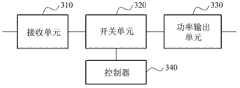
图3是示出无线功率接收器的框图。FIG. 3 is a block diagram illustrating a wireless power receiver.
图4是示出无线电力传输系统的框图。FIG. 4 is a block diagram illustrating a wireless power transmission system.
图5是示出无线电力传输系统的等效电路的示图。FIG. 5 is a diagram showing an equivalent circuit of a wireless power transmission system.
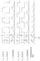
图6是示出当无线功率发送器中包括两个并联布置的电容器时开关的操作和存储的能量的示图。FIG. 6 is a diagram illustrating an operation of a switch and stored energy when two parallel-arranged capacitors are included in a wireless power transmitter.
图7是示出当无线功率接收器中包括两个并联布置的电容器时开关的操作和存储的能量的示图。FIG. 7 is a diagram illustrating an operation of a switch and stored energy when two parallel-arranged capacitors are included in a wireless power receiver.
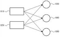
图8是示出在多个无线功率发送器和多个无线功率接收器之间的谐振功率传输的示图。FIG. 8 is a diagram illustrating resonance power transmission between a plurality of wireless power transmitters and a plurality of wireless power receivers.
图9是示出无线功率发送方法的流程图。FIG. 9 is a flowchart illustrating a wireless power transmission method.
图10是示出无线功率接收方法的流程图。FIG. 10 is a flowchart illustrating a wireless power receiving method.
在整个附图和详细的描述中,除非另外描述,相同的附图标号应该被理解为表示相同或相似的元件、特征和结构。为了清晰、说明和方便,可夸大这些元件的相对尺寸和描述。Throughout the drawings and detailed description, unless otherwise described, the same drawing reference numerals should be understood to refer to the same or similar elements, features, and structures. The relative size and description of these elements may be exaggerated for clarity, illustration, and convenience.
具体实施方式Detailed ways
提供下面的详细描述以帮助读者能够全面理解这里描述的方法、设备和/或系统。因此,在此描述的系统、设备和/或方法的各种修改、变型和等同物可被推荐给本领域的普通技术人员。描述的处理步骤和/或操作的进行是示例,然而,步骤和/或操作的顺序不限于在此阐述的顺序,而可如本领域所知地进行改变,除非步骤和/或操作必须按特定顺序发生。另外,为了更清晰和简洁,可省略对公知功能和构造的描述。The following detailed description is provided to assist the reader with a comprehensive understanding of the methods, devices and/or systems described herein. Accordingly, various modifications, variations, and equivalents of the systems, devices, and/or methods described herein may be suggested to those of ordinary skill in the art. The described performance of process steps and/or operations is an example, however, the order of steps and/or operations is not limited to the order set forth herein, but may be changed as known in the art, unless the steps and/or operations must be in a specific order. happen sequentially. Also, descriptions of well-known functions and constructions may be omitted for increased clarity and conciseness.
无线电力传输可应用于各种系统。例如,这种系统的示例可包括手机的无线充电器、无线电视(TV)等。无线电力传输也可以应用于生物/健康保健领域。具体地讲,无线电力传输可用于将功率发送到嵌入在人体内或位于人体附近的装置。例如,心率测量装置可被构造为无需有线连接的一种绷带。Wireless power transfer can be applied to various systems. Examples of such systems may include, for example, wireless chargers for cell phones, wireless televisions (TVs), and the like. Wireless power transmission can also be applied in the field of biology/health care. Specifically, wireless power transfer can be used to send power to devices that are embedded in or located near the body. For example, a heart rate measuring device can be configured as a type of bandage that does not require a wired connection.
在一个实施例中,无线电力传输可被用于不包括电源的信息存储装置的远程控制。并且,在另一实施例中,无线电力传输可应用于将功率远程提供给信息存储装置并无线读取存储在该信息存储装置中的信息的系统。In one embodiment, wireless power transfer can be used for remote control of information storage devices that do not include a power source. And, in another embodiment, wireless power transmission is applicable to a system that remotely supplies power to an information storage device and wirelessly reads information stored in the information storage device.
图1示出了传统的短距离无线电力传输系统的等效电路。Figure 1 shows the equivalent circuit of a conventional short-range wireless power transmission system.
这里,可假设使用图1中示出的无线电力传输系统传输的无线功率为谐振功率。Here, it may be assumed that wireless power transmitted using the wireless power transmission system shown in FIG. 1 is resonance power.
如图1所示,无线电力传输系统可包括源和目标(target)。无线电力传输系统可包括与源对应的无线功率发送器和与目标对应的无线功率接收器。例如,无线功率发送器可包括源单元110和源谐振器(resonator)120。源单元110可被构造为从电源接收能量或者可包括产生谐振功率的电源。源谐振器120可被构造为将电磁能发送到目标谐振器130。具体地讲,源谐振器120可被构造为通过与目标谐振器130的磁耦合来发送谐振功率。基于相应的物理性能,源单元110可被建模为包括电源Vin和内阻Rin,源谐振器120可被建模为包括电路元件、电阻R1、电感器L1和电容器C1。As shown in FIG. 1, a wireless power transfer system may include a source and a target. The wireless power transfer system may include a wireless power transmitter corresponding to a source and a wireless power receiver corresponding to a target. For example, the wireless power transmitter may include a
无线功率接收器可包括目标谐振器130和目标单元140。目标谐振器130可从源谐振器120接收电磁能。目标谐振器130可被构造为通过与目标谐振器130的磁耦合接收谐振功率。目标单元140可被构造为将接收的谐振功率发送到负载,或者可包括负载。目标谐振器130可被建模为包括电路元件、电阻器R2、电感器L2和电容器C2,并且目标单元可被建模为目标Zload。The wireless power receiver may include a
如图1所示,源单元110连接到源谐振器120,并且目标谐振器130连接到目标单元140。为了提高效率,无线电力传输系统可被如下的执行。As shown in FIG. 1 , the
首先,可基于源谐振器120和目标谐振器130之间的距离,将源谐振器120和目标谐振器130之间的操作频率进行匹配。使传输效率最大的频率可基于源谐振器120和目标谐振器130之间的距离而改变。因此,可随着源谐振器120和目标谐振器130之间的距离变化而调整操作频率。First, the operating frequencies between the
其次,可在无线功率发送器和无线功率接收器二者执行阻抗匹配。可执行阻抗匹配使得从电源发送到源谐振器120的功率最大化并且使从目标谐振器130发送到目标的功率最大化。另一方面,当阻抗不匹配时,谐振功率可能会被反射,并且传输效率会降低。可基于源谐振器120和目标谐振器130的特性、目标的阻抗以及将在源谐振器120和目标谐振器130之间被传输谐振功率到的信道的特性(例如,距离和/或传输介质等),来执行阻抗匹配。Second, impedance matching may be performed at both the wireless power transmitter and the wireless power receiver. Impedance matching may be performed to maximize power transmitted from the power source to the
第三,可在无线功率发送器中使用传输放大器,并且可在无线功率接收器中使用整流器。因此,可能需要增大功率放大器的效率来提高传输效率。Third, a transmit amplifier can be used in a wireless power transmitter and a rectifier can be used in a wireless power receiver. Therefore, it may be necessary to increase the efficiency of the power amplifier to improve the transmission efficiency.
因此,图1中的无线电力传输系统可被构造为基于操作环境的变化(诸如谐振器之间的距离变化和目标的改变)将频率进行匹配并执行阻抗匹配,并可使用有效的功率放大器和有效的整流器来提高传输效率。Therefore, the wireless power transmission system in FIG. 1 can be configured to match frequencies and perform impedance matching based on changes in operating environments such as distance changes between resonators and changes in targets, and can use efficient power amplifiers and Effective rectifiers to improve transmission efficiency.
图2示出了根据这里公开的一个或多个的实施例的无线功率发送器。Figure 2 illustrates a wireless power transmitter according to one or more embodiments disclosed herein.
如图2所示,无线功率发送器可包括功率输入单元210、开关单元220、发送单元230和控制器240。As shown in FIG. 2 , the wireless power transmitter may include a
功率输入单元210可被构造为从电源接收功率或者可包括电源,以对一个或多个电容器进行充电。例如,如果使用多个电容器,则可以以并联的方式布置所述多个电容器。尽管将理解的是电容器也可以以串联的方式布置,或者甚至可以以并联和串联组合的方式布置。The
功率输入单元210可被构造为接收从DC电源或AC电源输入的功率或者可包括DC电源或AC电源,以对一个或多个电容器进行充电。例如,功率输入单元210可被构造为使用DC电源直接对电容器进行充电。当使用AC电源时,功率输入单元210可被构造为使用AC/DC转换器将AC功率转换成DC功率,或者可添加开关并调整适当的时间来激活开关以对电容器进行充电。The
开关单元220可包括与一个或多个电容器分别对应的一个或多个开关(或开关元件),并可构造为单独地控制每个电容器的开关。开关或开关元件可包括各种机电开关(例如,接触、拨动(toggle)、闸刀、倾斜等)或电开关(例如,螺线管、继电器或诸如晶体管开关、可控硅整流器或三端双向可控硅开关的固态元件)。当然,其它类型的开关也是可行的。在各种实施例中,开关可被构造为在分别允许和防止电(功率)的流动的ON位置和OFF位置之间进行选择。因此,开关控制与一个或多个电容器的电连接和/或从一个或多个电容器的电连接,从而能够对所述一个或多个电容器进行充电和放电。例如,开关单元可被构造为为例如选择性地(i)对一个或多个电容器进行充电;(ii)从充电的一个或多个电容器释放功率。开关单元可由控制器进行控制。The
在无线功率发送器的一个实施例中,开关单元220可被构造为控制一个或多个电容器与功率输入单元210和/或发送单元230的电连接。例如,响应于控制器240,开关单元220可被构造为选择性地切换一个或多个电容器在功率输入单元210和发送单元230之间的电连接。In one embodiment of the wireless power transmitter, the
例如,所述切换可基于对电容器进行充电的充电时间和/或将存储在电容器中的功率发送到源谐振器的发送时间。在对一个或多个电容器进行充电的充电时间期间,开关单元220可将电容器连接到功率输入单元210。例如,一个或多个电容器可通过一个或多个开关的闭合/断开操作连接到功率输入单元210。在电容器连接到功率输入单元210的同时,电容器可与发送单元230分开。因此,功率输入单元210和发送单元230可通过开关单元220的开关操作而相互电分离(或隔离)。For example, the switching may be based on a charging time for charging the capacitor and/or a sending time for sending power stored in the capacitor to the source resonator. During a charging time for charging one or more capacitors, the
可通过将一个或多个充电的电容器电连接到源谐振器,来执行将存储在电容器中的功率发送到源谐振器的处理。在发送时间期间,开关单元220可将一个或多个充电的电容器连接到发送单元230。一个或多个充电的电容器可仅电连接到发送单元230,因此,功率输入单元210可与发送单元230电分离并隔离。The process of transmitting power stored in the capacitors to the source resonator may be performed by electrically connecting one or more charged capacitors to the source resonator. During the transmission time, the
开关单元220可被构造为将一个或多个电容器选择性地连接到功率输入单元210或发送单元230。在一些实施方式中,充电成电平高于或等于预定电平的电容器可连接到发送单元230,充电成电平低于预定电平的电容器可连接到功率输入单元210。在实施例中,通常没有电容器同时连接到功率输入单元210和发送单元230。尽管也不是总是这种情况。开关单元220可在电容器连接到功率输入单元210预定时间之后将该电容器连接到传输单元230。并且,开关单元220可控制开关以使充电时间和发送时间交替。The
例如,可基于电源的充电能力来确定充电时间。如果电源具有快速的充电能力,则充电时间可较短。可基于由于谐振功率发送而存储在电容器中的功率的放电程度来确定发送时间。可基于存储在电容器中的功率的放电速度来确定发送时间,其中,发送时间也表示放电时间。For example, the charging time may be determined based on the charging capability of the power source. The charging time can be shorter if the power source has fast charging capability. The transmission time may be determined based on the degree of discharge of power stored in the capacitor due to resonance power transmission. The transmission time may be determined based on the discharge rate of the power stored in the capacitor, wherein the transmission time also represents the discharge time.
开关单元220可被构造为控制开关以防止针对每个电容器的充电时间和发送时间相互重叠。这是因为当充电时间和发送时间相互重叠时,功率输入单元210和发送单元230可相互物理且电连接。并且,当功率输入单元210和发送单元230相互物理且电连接时,会产生使性能劣化的因素,诸如阻抗不匹配等。The
发送单元230可被构造为将谐振功率发送到目标谐振器。在一些实施例中,例如,谐振功率可通过磁耦合来被发送。其它的谐振功率发送方法也是可行的。当充电的电容器通过开关单元220电连接到源谐振器时,发送单元230可例如通过磁耦合发送存储在充电的电容器中的功率。The transmitting
控制器240可被构造为感测存储在电容器中的一个或多个电容器中的功率并可控制电容器中的一个或多个电容器的充电时间和发送时间。例如,控制器240可感测存储在连接到功率输入单元210的多个电容器中的功率。当多个电容器被充电成电平高于或等于预定电平时,它们可连接到传输单元230。预定电平可设置成电容器的最大充电电平,或者预定电平可设置成基于电容器的稳定性确定的值。因此,控制器240可被构造为感测存储在电容器中的连接到传输单元230的一个或多个电容器中的功率。当电容器被充电成电平低于或等于预定值时,它们可连接到功率输入单元210。预定值例如可为零。The
控制器240可被构造为检测在多个电容器中充电成电平低于预定值的一个或多个电容器。控制器240可控制检测的电容器将被电源进行充电的充电时间。例如,控制充电时间可表示控制检测的电容器以将被连接到功率输入单元210。The
此外,控制器240可被构造为检测在多个电容器中充电成电平高于或等于预定电平的一个或多个电容器。例如,控制器240可控制存储在检测的电容器中的功率将发送到源谐振器的发送时间。控制发送时间可表示控制检测的电容器以将被连接到发送单元230。In addition, the
控制器240可控制充电时间并连续对多个电容器进行充电,直到电容器中的一个或多个电容器被充电至高于或等于预定电平的电平。另外,控制器240可控制充电时间并优选地对多个电容器中的一个或多个电容器进行充电,以对它们进行充电。The
控制器240可控制发送时间,直到连接到源谐振器的多个电容器的功率由于无线功率发送而降低至低于预定值的电平。例如,控制器240可控制将连接到源谐振器的电容器用于放电的发送时间。并且,开关单元220可控制开关,使得电容器基于发送时间连接到源谐振器。The
当一个或多个充电的电容器的功率降低至低于或等于预定值的电平时,控制器240可被构造为控制那些电容器被电源充电的充电时间,以将它们的功率重新充至预定值(即,对它们进行再充电)。而且,控制器240可被构造为控制放电的电容器将被电源充电的充电时间,并且开关单元220可控制开关使得放电的电容器连接到电源。When the power of one or more charged capacitors decreases to a level below or equal to a predetermined value, the
在无线功率发送器中,功率输入单元210和发送单元230可通过开关单元220相互电分离,并且可使用并联布置的一个或多个电容器。功率输入单元210可被构造为对连接到功率输入单元210的一个或多个电容器进行充电,并且发送单元230可利用谐振无线发送存储在电容器中的功率。由于功率输入单元210和发送单元230电分离,所以无线功率发送器的操作环境的变化应该不会对它们产生不利的影响。因此,在不使用功率放大器的情况下,功率输入单元210可使用一个或多个电容器对目标装置提供足够的功率。In the wireless power transmitter, the
图3示出了无线功率接收器。Figure 3 shows a wireless power receiver.
如图3所示,无线功率接收器可包括接收单元310、开关单元320、功率输出单元330和控制器340。As shown in FIG. 3 , the wireless power receiver may include a receiving
接收单元310可被构造为利用谐振无线地接收功率并对一个或多个电容器进行充电。如果包括多个电容器,则多个电容器可以按照并联的方式布置。尽管将理解的是电容器也可以按串联方式布置,或者甚至以并联和串联组合的方式布置。The receiving
开关单元320可被构造为基于用于对电容器进行充电的充电时间和/或用于将存储在一个或多个电容器中的功率发送到目标装置的发送时间来控制与一个或多个电容器分别对应的开关。The
开关单元320可包括与一个或多个电容器分别对应的一个或多个开关(或开关元件)并被构造为单独控制每个电容器的开关。开关或开关元件可包括与开关单元220(图2)相似的元件。在各种实施例中,开关可被构造为在分别允许和防止电(功率)的流动的ON位置和OFF位置之间进行选择。因此,开关控制与一个或多个电容器和/或从一个或多个电容器的电连接,因此能够对所述一个或多个电容器进行充电和放电。例如,开关单元可被构造为例如选择性地(i)对一个或多个电容器进行充电,并且(ii)从充电的一个或多个电容器释放功率。开关单元可由控制器控制。The
在无线功率接收器的一个实施例中,开关单元320可被构造为控制电容器中的一个或多个电容器与接收单元310和/或功率输出单元330的电连接。例如,响应于控制器340,开关单元320可被构造为可选择性地切换一个或多个电容器在接收单元310和功率输出单元330之间的电连接。In one embodiment of the wireless power receiver, the
在充电时间期间,开关单元320可将将被充电的一个或多个电容器连接到接收单元310。例如,将被充电的电容器可通过开关的闭合/断开操作连接到接收单元310。并且,在将被充电的电容器连接到接收单元310的同时,所述电容器与功率输出单元330分开。因此,接收单元310和功率输出单元330可通过开关单元320的切换操作彼此电分离。During the charging time, the
可通过将充电的电容器连接到目标装置,来执行将存储在充电的电容器中的功率发送到目标装置。在发送时间期间,开关单元320可将充电的电容器电连接到功率输出单元330。充电的电容器可电连接到功率输出单元330,并且接收单元310可与功率输出单元330电分离(或隔离)。Transmitting the power stored in the charged capacitor to the target device may be performed by connecting the charged capacitor to the target device. During the transmission time, the
在一些实施例中,可基于使电容器充电至高于或等于预定电平的电平所花费的时间确定充电时间。还可以基于源谐振器发送的谐振功率的量或者目标谐振器接收的且用于对电容器充电的功率的量来确定充电时间。可基于发送到目标装置的功率的量确定传输时间。例如,可基于存储在电容器中的功率的放电速度确定可与放电时间相同的发送时间。In some embodiments, the charge time may be determined based on the time it takes to charge the capacitor to a level greater than or equal to a predetermined level. The charging time may also be determined based on the amount of resonance power transmitted by the source resonator or the amount of power received by the target resonator and used to charge the capacitor. The transmission time may be determined based on the amount of power sent to the target device. For example, the transmission time, which may be the same as the discharge time, may be determined based on the discharge speed of the power stored in the capacitor.
在一些实施例中,开关单元320可被构造为针对每个电容器控制开关使得在充电时间和发送时间之间具有等待时间。如果充电时间和发送时间相互重叠,则接收单元310和功率输出单元330可物理且电连接。另一方面,当接收单元310和功率输出单元330物理且电连接时,可产生使性能劣化的因素(诸如阻抗不匹配等)。因此,开关单元320可被构造为控制一个或多个开关使得发送时间在充电时间之后的预定时间开始。在一些情况下,开关单元320可被构造为控制一个或多个开关以使充电时间和发送时间交替。In some embodiments, the
功率输出单元330可被构造为将存储在电容器中的功率发送到目标装置或可包括目标装置。由接收单元310充电的电容器可通过开关单元320连接到目标装置。例如,功率输出单元330可将存储在电容器中的功率发送到目标装置。The
控制器340可被构造为感测存储在电容器中的功率并可控制充电时间和发送时间。控制器340可感测存储在连接到接收单元310的电容器中的功率。并且,当电容器被充电至高于或等于预定电平的电平时,该电容器可连接到功率输出单元330。例如,预定电平可为电容器的最大充电电平。可基于存储的功率的一阶微分是零还是接近零来确定电容器是否充电至最大充电电平。当目前存储的功率和先前采样时间的存储功率之间的差小于指定值时,可确定或假设电容器被充电至最大充电电平。The
另外,控制器340可被构造成感测存储在连接到功率输出单元330的电容器的功率。当电容器被放电至小于预定值的电平时,该电容器可连接到接收单元310。例如,预定值可为零。并且当存储的功率为零或接近零时,控制器340可控制用于将电容器充电至高于或等于预定电平的电平的充电时间。例如,控制充电时间可指示存储在的功率为零或接近零的电容器连接到接收单元310。开关单元320可基于充电时间控制开关将放电的电容器连接到接收单元310。In addition, the
控制器340还可控制用于将存储在充电至高于或等于预定电平的电平的电容器中的功率发送至目标装置的发送时间。例如,控制发送时间可指示功率输出单元330电容器是否被充电至高于或等于预定电平的电平。开关单元320可基于发送时间控制开关将充电的电容器连接到目标装置。The
当由于至目标装置的功率发送而使电容器放电时,控制器340可控制充电时间以使用接收的谐振功率对该电容器进行充电。When the capacitor is discharged due to power transmission to the target device, the
在无线功率接收器中,接收单元310和功率输出单元330可通过开关单元320相互电分开。一个或多个电容器可位于接收单元310和功率输出单元330之间并通过开关单元320相互连接。这样,接收单元310可对连接到接收单元310的一个或多个电容器进行充电。并且,功率输出单元330可被构造为将存储在一个或多个电容器中的功率发送到目标装置。由于接收单元310和功率输出单元330电分开,所以无线功率发送器的操作环境的改变通常不该会对它们产生不利影响。在不使用整流器的情况下,接收单元310可使用一个或多个电容器将足够的功率发送到目标装置。In the wireless power receiver, the receiving
图4示出了无线电力传输系统。Fig. 4 shows a wireless power transfer system.
如图4所示,在无线电力传输系统中,功率输入单元410和发送单元420相互物理且电分开,并且接收单元440和功率输出单元450相互物理且电分开。As shown in FIG. 4 , in the wireless power transmission system, the
功率输入单元410可包括电源Vin和并联布置的多个电容器。在图4中,电容器被示出为具有与电池的形状相似的形状。功率输入单元410可使用电源Vin对多个电容器进行充电。充电的电容器可通过切换操作411连接到发送单元420。发送单元420可被构造为通过源谐振器发送存储在电容器中的功率。如标号413所表示的,当源谐振器通过与目标谐振器的磁耦合发送功率时,连接到传输单元420的电容器可被放电。放电的电容器可通过切换操作415连接到功率输入单元410。The
可通过接收单元440的目标谐振器来接收通过源谐振器从发送单元420发送的谐振功率。例如,源谐振器和目标谐振器可通过预定信道430发送和接收谐振功率。预定信道430可包括源谐振器和目标谐振器之间的操作频带。接收单元440可包括图4中表示的具有与电池的形状相似的形状的一个或多个电容器,并且可使用接收的谐振功率对所述一个或多个电容器进行充电。充电的电容器可通过切换操作441连接到功率输出单元450。因此,功率输出单元450可被构造为将存储在连接到功率输出单元450的电容器中的功率发送到目标装置。随着功率被发送到目标装置,如标号443所示,电容器被放电。放电的电容器可通过切换操作445连接到接收单元440。The resonance power transmitted from the transmitting
功率输入单元410和发送单元420可相互电分开。接收单元440和功率输出单元450可相互电分开。换言之,源谐振器和电源Vin可相互电分开(或隔离),并且目标谐振器和目标装置可相互电分开(或隔离)。因此,可不需要执行基于操作环境的变化的频率匹配和阻抗匹配。可基于存储在连接到传输单元420的多个电容器中的功率确定从源谐振器发送的功率,并且可基于存储在连接到功率输出单元450的一个或多个电容器中的功率确定发送到目标装置的功率。因此,与操作环境的变化无关,可基于电容器的充电和存储在电容器中的功率的传输确定传输效率。The
图5示出了无线电力传输系统的等效电路。FIG. 5 shows an equivalent circuit of the wireless power transmission system.
如图5所示,无线电力传输系统可包括功率输入单元510、第一开关单元520、传输单元530、接收单元540、第二开关单元550和功率输出单元560。As shown in FIG. 5 , the wireless power transmission system may include a
功率输入单元510可从电源接收功率或者包括电源,以对并联布置的多个电容器进行充电。第一开关单元520可被构造为基于对多个电容器进行充电的第一充电时间以及将存储在所述多个电容器中的功率发送到发送单元530的第一发送时间来控制多个第一开关。发送单元530可通过磁耦合将谐振功率发送到接收单元540。接收单元540可接收谐振功率以对一个或多个电容器进行充电。第二开关单元550可基于对一个或多个电容器进行充电的第二充电时间以及将存储在所述一个或多个电容器中的功率发送到目标装置LOAD的第二发送时间来控制多个第二开关。功率输出单元560可被构造为将存储在一个或多个电容器中的功率发送到目标装置LOAD或者可包括目标装置LOAD。目标装置可包括功耗元件或节能元件,诸如电池。The
功率输入单元510可包括电源Vin、内阻Rin和并联布置的多个电容器C1,1、...、C1,n。功率输入单元510可利用电源Vin提供的功率对多个电容器进行充电。例如,多个电容器C1,1、...、C1,n可通过第一开关单元520连接到功率输入单元510。当在第一开关单元520中的开关521和525处于“ON”位置时,多个电容器C1,1、...、C1,n可连接到功率输入单元510。开关521和525可一起处于“ON”位置,或者可单独地处于“ON”位置。The
发送单元530可包括具有基础电路元件L1和R1以及多个电容器C1,1、...、C1,n的源谐振器。换言之,基础电路元件L1和R1与多个电容器C1,1、...、C1,n一起形成无线功率发送电路。由功率输入单元510充电的多个电容器C1,1、...、C1,n可通过第一开关单元520连接到发送单元530。当在第一开关单元520中的开关523和开关527处于“ON”位置时,充电的多个电容器C1,1、...、C1,n可连接到发送单元530。例如,当电容器C1,1连接到功率输入单元510时,电容器C1,1不会同时连接到发送单元530。类似地,当电容器C1,n连接到功率输入单元510时,电容器C1,n不会同时连接到发送单元530。因此,第一开关单元520可将开关521和开关523以规则的间隔切换到“ON”位置。发送单元530可发送存储在连接到它的多个电容器中的功率。例如,可使用谐振无线地发送功率。The
接收单元540可包括具有基础电路元件L2和R2以及电容器C2,1、...、C2,m的目标谐振器。换言之,基础电路元件L2和R2与电容器C2,1、...、C2,m一起形成无线功率接收电路。尽管图5示出了多个电容器C2,1、...、C2,m,但是也可以使用单个电容器代替。接收单元540可使用从发送单元530接收的谐振功率对电容器C2,1、...、C2,m进行充电。例如,电容器C2,1、...、C2,m可通过第二开关单元550连接到接收单元540。当在第二开关单元550中的开关553和开关557处于“ON”状态时,电容器C2,1、...、C2,m可连接到接收单元540。开关553和开关557可一起处于“ON”位置,或者可单独地处于“ON”位置。The receiving
功率输出单元560可包括目标装置LOAD。通过接收单元540进行充电的电容器C2,1、...、C2,m可通过第二开关单元550连接到功率输出单元530。当在第二开关单元550中的开关551和开关555处于“ON”位置时,电容器C2,1、...、C2,m可连接到功率输出单元560。例如,当电容器C2,1连接到接收单元540时,电容器C2,1不会同时连接到功率输出单元560。类似地,当电容器C2,m连接到接收单元540时,电容器C2,m不会同时连接到功率输出单元560。因此,第二开关单元550可以以规则的间隔使开关551和开关553切换到“ON”位置。功率输出单元560可包括目标装置LOAD或者将存储在电容器C2,1、...、C2,m中的功率发送到目标装置LOAD。The
第一开关单元520可针对每个电容器C1,n控制开关525和527以防止第一充电时间和第一发送时间相互重叠。如果第一充电时间和第一发送时间相互重叠,则功率输入单元510和传输单元530物理且电连接,因此,可能会发生不匹配。The
第二开关单元550可针对每个电容器C2,m控制第二开关555和557以防止第二充电时间和第二发送时间相互重叠。The
在一些实施例中,第一开关单元520和第二开关单元550可为非同步的,并可基于第一发送时间和第二发送时间分别控制开关523和开关527以及开关553和开关557。发送单元530仅发送谐振功率并且接收单元540仅接收谐振功率,因此,当在发送单元530中的开关523和开关527为ON时,在接收单元540中的开关553和开关557不会同时为ON。在其它实施例中,尽管开关可为同步的。In some embodiments, the
图6示出了当图5中的无线功率发送器中包括两个并联布置的电容器时开关的操作和存储的能量。FIG. 6 illustrates the operation of switches and stored energy when two capacitors arranged in parallel are included in the wireless power transmitter of FIG. 5 .
图5中的无线功率发送器可包括连接到功率输入单元510或发送单元530的两个电容器C1,1和C1,2。如图6所示,充电开关表示连接到功率输入单元510的开关,发送开关表示连接到发送单元530的开关。The wireless power transmitter in FIG. 5 may include two capacitors C1,1 and C1,2 connected to the
当电容器C1,1的充电开关在时间段611工作时,电容器C1,1的发送开关在时间段615不工作。因此,与电容器C1,1相关的充电时间和发送时间不会相互重叠。当电容器C1,1的充电开关在时间段613不工作时,电容器C1,1的发送开关在时间段617工作。并且,当电容器C1,1的充电开关在时间段611工作时,电容器C1,1可在时间段619通过电源进行充电。一旦存储在电容器C1,1中的能量达到预定电平,则电容器C1,1的发送开关可工作。当电容器C1,1的发送开关在时间段617工作时,存储在充电的电容器C1,1中的功率可被发送到源谐振器,并且电容器C1,1可在时间段621进行放电。当电容器C1,1进行放电并且存储的能量减少至低于或等于预定值时,电容器C1,1的充电开关可再次工作。While the charge switch of capacitor C1,1 is active in
例如,电容器C1,2和电容器C1,1可被交替地充电和放电以将功率连续输出到源谐振器。当电容器C1,2的充电开关在时间段623不工作时,电容器C1,2的发送开关在时间段627工作。当电容器C1,2的充电开关在时间段625工作时,电容器C1,2的发送开关在时间段629不工作。当电容器C1,2的充电开关在时间段625工作时,电容器C1,2可在时间段633通过电源进行充电。当存储在电容器C1,2中的能量达到预定电平时,电容器C1,2的发送开关可工作。当电容器C1,2的发送开关在时间段627工作时,存储在电容器C1,2中的功率可被发送到源谐振器,并且电容器C1,2可在时间段631进行放电。当电容器C1,2放电且存储的能量减少至小于或等于预定值时,电容器C1,2的充电开关可再次工作。通过重复地执行上述操作,能量可被连续地发送到源谐振器。这样,源谐振器可在时间段635和637从电容器C1,1和电容器C1,2连续接收能量。在一些实施例中,对于同一电容器,可在充电时间和发送时间之间插入等待时间639,以防止充电时间和发送时间相互重叠。For example, the capacitors C1,2 and C1,1 may be alternately charged and discharged to continuously output power to the source resonator. When the charging switch of capacitor C1,2 is inactive for
图7示出了当图5中的无线功率接收器包括两个并联布置的电容器时开关的操作和存储的能量。FIG. 7 illustrates operation of switches and stored energy when the wireless power receiver in FIG. 5 includes two capacitors arranged in parallel.
图5中的无线功率接收器可包括连接到接收单元540或功率输出单元560的两个电容器C2,1和C2,2。如图7所示,充电开关表示连接到接收单元540的开关,发送开关表示连接到功率输出单元560的开关。The wireless power receiver in FIG. 5 may include two capacitors C2,1 and C2,2 connected to the receiving
当电容器C2,1的充电开关在时间段711工作时,电容器C2,1的发送单元在时间段715不工作。因此,与同一电容器相关的充电时间和发送时间不会相互重叠。当电容器C2,1的充电开关在时间段713不工作时,电容器C2,1的发送开关在时间段717工作。当电容器C2,1的充电开关在时间段711工作时,电容器C2,1可在时间段719使用通过目标谐振器接收的谐振功率进行充电。当存储在电容器C2,1中的能量达到预定电平时,电容器C2,1的发送开关可工作。当电容器C2,1的发送开关在时间段717工作时,存储在充电的电容器C2,1中的功率可被发送到目标装置,并且电容器C2,1可在时间段721被放电。当电容器C2,1被放电并且存储的能量减少至小于或等于预定值时,电容器C2,1的充电开关可再次工作。When the charging switch of the capacitor C2,1 works in the time period 711 , the sending unit of the capacitor C2,1 does not work in the time period 715 . Therefore, charging time and sending time related to the same capacitor do not overlap each other. When the charging switch of capacitor C2,1 is inactive for time period 713 , the transmit switch of capacitor C2,1 is active for time period 717 . When the charging switch of the capacitor C2,1 is operated at the time period 711 , the capacitor C2,1 may be charged with the resonant power received through the target resonator at the time period 719 . When the energy stored in the capacitorC2,1 reaches a predetermined level, the transmit switch of the capacitorC2,1 is operable. When the transmit switch of capacitor C2,1 is activated at time period 717 , power stored in charged capacitor C2,1 may be transmitted to the target device, and capacitor C2,1 may be discharged at time period 721 . When the capacitorC2,1 is discharged and the stored energy decreases to less than or equal to a predetermined value, the charging switch of the capacitorC2,1 may work again.
例如,电容器C2,1和电容器C2,2可被交替地充电和放电以将功率连续地发送到目标装置。当电容器C2,2的充电开关在时间段723不工作时,电容器C2,2的发送开关在时间段727工作。当电容器C2,2的充电开关在时间段725工作时,电容器C2,2的发送开关在时间段729不工作。当电容器C2,2的充电开关在时间段725工作时,可在时间段733使用通过目标谐振器接收的谐振功率对电容器C2,2进行充电。一旦存储在电容器C2,2中的能量达到预定电平,则电容器C2,2的发送开关可工作。当电容器C2,2的发送开关在时间段727工作时,存储在电容器C2,2中的功率可被发送到目标装置,并且电容器C2,2可在时间段731被放电。当电容器C2,2被放电并且存储的能量减少到小于或等于预定值时,电容器C2,2的充电开关可再次工作。通过重复地执行上述操作,功率可被连续发送到目标装置。目标装置可在时间段735和737从电容器C2,1和电容器C2,2连续接收能量。在一些实施例中,对于同一电容器,可在充电时间和发送时间之间插入等待时间739以防止充电时间和发送时间相互重叠。For example, capacitorC2,1 and capacitorC2,2 may be alternately charged and discharged to continuously send power to the target device. When the charge switch of capacitor C2,2 is inactive for time period 723 , the transmit switch of capacitor C2,2 is active for time period 727 . While the charge switch of capacitor C2,2 is active for time period 725 , the transmit switch for capacitor C2,2 is deactivated for time period 729 . When the charging switch of capacitor C2,2 is active at time period 725 , capacitor C2,2 may be charged at time period 733 using the resonant power received through the target resonator. Once the energy stored in the capacitor C2,2 reaches a predetermined level, the transmit switch of the capacitor C2,2 is operable. When the transmit switch of capacitor C2,2 is activated at time period 727 , the power stored in capacitor C2,2 may be transmitted to the target device, and capacitor C2,2 may be discharged at time period 731 . When the capacitorC2,2 is discharged and the stored energy is reduced to less than or equal to a predetermined value, the charging switch of the capacitorC2,2 can work again. By repeatedly performing the above operations, power can be continuously transmitted to the target device. The target device may continuously receive energy from capacitors C2,1 and C2,2 for time periods 735 and 737 . In some embodiments, for the same capacitor, a wait time 739 may be inserted between the charging time and the sending time to prevent the charging time and sending time from overlapping each other.
图8示出了多个无线功率发送器和多个无线功率接收器之间的谐振功率传输。FIG. 8 illustrates resonant power transfer between multiple wireless power transmitters and multiple wireless power receivers.
如以上参照图6和图7所述,无线功率发送器和无线功率接收器可单独地确定充电时间和发送时间。例如,无线功率发送器可确定充电时间和发送时间以提高发送效率。并且,无线功率接收器可确定充电时间和发送时间以提高接收效率。因此,即使无线功率发送器和无线功率接收器被单独控制,也可以保持传输效率。As described above with reference to FIGS. 6 and 7 , the wireless power transmitter and the wireless power receiver may individually determine the charging time and the transmitting time. For example, a wireless power transmitter may determine charging time and transmission time to improve transmission efficiency. And, the wireless power receiver may determine charging time and transmission time to improve reception efficiency. Therefore, transmission efficiency can be maintained even if the wireless power transmitter and the wireless power receiver are individually controlled.
在图8中,示出了两个无线功率发送器810和820以及三个无线功率接收器830、840和850。无线功率发送器810可将谐振功率发送到三个无线功率接收器无。例如,无线功率发送器810可被优化为在短时间内对多个电容器进行充电并通过源谐振器发送谐振功率。无线功率接收器830、840和850中的每个可被优化为或另外被构造为在短时间内使用接收的谐振功率对一个或多个电容器进行充电并将功率发送到目标装置。因此,不管工作环境中的变化如何(诸如,目标装置的距离和变化),可保持传输效率。无线功率发送器820还可在保持传输效率的同时将谐振功率发送到三个无线功率接收器830、840和850。In FIG. 8, two
图9示出了无线功率发送方法。FIG. 9 shows a wireless power transmission method.
在操作910,无线功率发送器可确定在连接到功率输入单元的多个电容器中是否存在充电的电容器。当确定充电的电容器时,在操作920,充电的电容器可通过切换操作连接到发送单元。在操作930,发送单元可通过源谐振器发送从充电的电容器接收的功率。然而,当一个或多个电容器没有被充分充电时,在操作940,功率输入单元可对连接到功率输入单元的一个或多个电容器进行充电。并且当充电的电容器(例如,由于谐振功率发送而)开始放电时,在操作950,放电的电容器可通过切换操作再次连接到功率输入单元。在操作960,连接到功率输入单元的放电的电容器可被充电。通过重复地执行上述操作(如果需要),功率可被连续地发送到源谐振器。根据功率需求,电容器可被充分放电或部分放电。In
图10示出了无线功率接收方法。FIG. 10 shows a wireless power receiving method.
在操作1010,无线功率接收器确定连接到接收单元的一个或多个电容器中是否存在充电的电容器。如果确定充电的电容器,则在操作1020,充电的电容器可通过切换操作连接到功率输出单元。在操作1030,功率输出单元可将从充电的电容器接收的功率发送到目标装置。另一方面,如果电容器没被充电,则在操作1040,接收单元可对连接到接收单元的电容器进行充电。然后可通过将功率发送到目标装置来对充电的电容器进行放电,因此,在操作1050,充电的电容器可通过切换再次连接到接收单元。在操作1060,可对连接到接收单元的放电的电容器进行充电。通过重复地执行上述操作(如果需要),功率可被连续地发送到目标装置。根据功率需求,电容器可被充分放电或部分放电。In
上述实施例中的一个或多个可记录在永久性计算机可读介质上,所述介质包括实现由具有一个或多个处理器的计算机或计算装置实施的各种操作的程序指令。所述介质还可以单独包括数据文件和/或数据结构等,或者与程序指令组合地包括数据文件和/或数据结构等。永久性计算机可读介质的示例可包括:磁介质,诸如硬盘、软盘和磁带;光介质,诸如CD ROM盘和DVD;磁光介质,诸如光盘;硬件装置,特别构造为存储并执行程序指令,诸如只读存储器(ROM)、随机存取存储器(RAM)和/或闪速存储器等。程序指令的示例既包括机器代码(诸如编译器产生的)又包括含有使用解释器可由计算机执行的高级代码的文件。描述的硬件装置可被构造为实施为一个或多个软件模块,从而执行上述的示例实施例的操作,或者反之亦然。另外,永久性计算机可读存储介质可分布通过网络连接的计算机系统中,并且永久性计算机可读代码或程序指令可以以分散的方式存储和执行。One or more of the above-described embodiments may be recorded on non-transitory computer-readable media including program instructions to implement various operations implemented by a computer or computing device having one or more processors. The media may also include data files and/or data structures, etc. alone or in combination with program instructions. Examples of non-transitory computer readable media may include: magnetic media, such as hard disks, floppy disks, and magnetic tape; optical media, such as CD ROM disks and DVDs; magneto-optical media, such as optical disks; hardware devices, specially constructed to store and execute program instructions, Such as read only memory (ROM), random access memory (RAM), and/or flash memory, among others. Examples of program instructions include both machine code (such as produced by a compiler) and files containing high-level code executable by a computer using an interpreter. The described hardware devices may be configured to be implemented as one or more software modules in order to perform the operations of the example embodiments described above, or vice versa. Also, non-transitory computer-readable storage media can be distributed over network-connected computer systems, and non-transitory computer-readable codes or program instructions can be stored and executed in a decentralized manner.
以上已经描述了多个示例实施例。然而,应该理解的是,可进行各种变型。例如,如果按照不同的顺序执行描述的技术和/或如果以不同的方式组合和/或用其他组件或它们的等价物代替或补充描述的系统中的组件、体系机构、装置或电路,则可实现适合的结果。因此,其它实施方式在权利要求的范围内。A number of example embodiments have been described above. However, it should be understood that various modifications may be made. For example, if the described techniques are performed in a different order and/or if components, architectures, devices or circuits in the described systems are combined in a different manner and/or replaced or supplemented with other components or their equivalents, it may be achieved suitable result. Accordingly, other implementations are within the scope of the following claims.
Claims (34)
Translated fromChineseApplications Claiming Priority (3)
| Application Number | Priority Date | Filing Date | Title |
|---|---|---|---|
| KR10-2010-0090810 | 2010-09-15 | ||
| KR1020100090810AKR101730406B1 (en) | 2010-09-15 | 2010-09-15 | Apparatus for wireless power transmission and reception |
| PCT/KR2011/005764WO2012036380A2 (en) | 2010-09-15 | 2011-08-08 | Apparatus for wireless power transmission and reception |
Publications (2)
| Publication Number | Publication Date |
|---|---|
| CN103109439Atrue CN103109439A (en) | 2013-05-15 |
| CN103109439B CN103109439B (en) | 2016-03-16 |
Family
ID=45806036
Family Applications (1)
| Application Number | Title | Priority Date | Filing Date |
|---|---|---|---|
| CN201180044592.1AActiveCN103109439B (en) | 2010-09-15 | 2011-08-08 | For the equipment that wireless power sends and receives |
Country Status (6)
| Country | Link |
|---|---|
| US (1) | US9252604B2 (en) |
| EP (1) | EP2617119B1 (en) |
| JP (1) | JP5774109B2 (en) |
| KR (1) | KR101730406B1 (en) |
| CN (1) | CN103109439B (en) |
| WO (1) | WO2012036380A2 (en) |
Cited By (2)
| Publication number | Priority date | Publication date | Assignee | Title |
|---|---|---|---|---|
| CN102801218A (en)* | 2011-05-27 | 2012-11-28 | 三星电子株式会社 | Wireless power and data transmission system |
| CN109301944A (en)* | 2017-07-24 | 2019-02-01 | 三星电子株式会社 | Wireless power receiving apparatus and method |
Families Citing this family (23)
| Publication number | Priority date | Publication date | Assignee | Title |
|---|---|---|---|---|
| JP5674013B2 (en)* | 2010-10-08 | 2015-02-18 | ソニー株式会社 | Power supply device and power supply system |
| KR102020869B1 (en)* | 2011-08-24 | 2019-09-11 | 삼성전자주식회사 | Communication system using wireless power |
| JP2013055835A (en)* | 2011-09-06 | 2013-03-21 | Sony Corp | Power feed unit, electronic appliance, and power feed system |
| KR101844422B1 (en)* | 2012-04-19 | 2018-04-03 | 삼성전자주식회사 | Apparatus and method for wireless energy transmission and apparatus wireless energy reception |
| JP5847651B2 (en)* | 2012-06-01 | 2016-01-27 | 株式会社東芝 | Power receiving device and power transmitting / receiving system |
| US9583948B2 (en) | 2012-10-26 | 2017-02-28 | Analog Devices, Inc. | Isolated digital transmission with improved EMI immunity |
| JP5954788B2 (en)* | 2012-12-28 | 2016-07-20 | セイコーインスツル株式会社 | Electronic component, power receiving device, and power feeding system |
| KR101497140B1 (en)* | 2013-01-09 | 2015-03-03 | 한국전기연구원 | Wireless Power Transfer System for Free Positioning Charging of Multiple Devices |
| KR101420563B1 (en)* | 2013-01-25 | 2014-07-17 | 홍익대학교 산학협력단 | Resonator for 3d wireless power transfer, method of selecting resonator mode and system |
| EP2944158B1 (en) | 2013-02-11 | 2021-04-07 | The Regents of The University of California | Fractional turn coil winding |
| CN106155262A (en)* | 2015-03-31 | 2016-11-23 | 技嘉科技股份有限公司 | Electronic device with biosensing device |
| CN105827021B (en)* | 2016-05-12 | 2018-01-16 | 陈文芗 | A kind of inductive coupling type electric energy amount radio transmitting device and transmission method |
| US11237595B2 (en) | 2016-06-06 | 2022-02-01 | Omnicharge, Inc. | Portable power solutions |
| US10630085B2 (en)* | 2016-06-06 | 2020-04-21 | Omnicharge, Inc. | Portable power solutions |
| CN110089003A (en) | 2016-11-02 | 2019-08-02 | Tdk电子股份有限公司 | Wireless power transmitter, wireless power emission system and the method for driving wireless power emission system |
| EP3327897B1 (en)* | 2016-11-25 | 2021-06-16 | Nxp B.V. | Apparatus and associated method |
| JP6756639B2 (en)* | 2017-02-22 | 2020-09-16 | エイブリック株式会社 | Power supply system, power receiving device, and power supply method |
| US20180353764A1 (en) | 2017-06-13 | 2018-12-13 | Bluewind Medical Ltd. | Antenna configuration |
| KR102399600B1 (en)* | 2017-09-25 | 2022-05-18 | 삼성전자주식회사 | Antenna device to include antenna elements mutually coupled |
| US11121583B2 (en)* | 2018-01-23 | 2021-09-14 | Stryker Corporation | Operating room wireless power transfer |
| DE102018124902A1 (en) | 2018-10-09 | 2020-04-09 | Endress+Hauser SE+Co. KG | Field device adapter for wireless data transmission |
| KR102191041B1 (en)* | 2019-01-30 | 2020-12-14 | 경상대학교 산학협력단 | Electromagnetic peening device |
| US11979035B2 (en)* | 2019-08-19 | 2024-05-07 | Omron Corporation | Wireless power transmission system for wirelessly transmitting power to prevent power shortage in load device of wireless power receiving apparatus |
Citations (4)
| Publication number | Priority date | Publication date | Assignee | Title |
|---|---|---|---|---|
| JPH10313260A (en)* | 1997-05-13 | 1998-11-24 | Matsushita Electric Ind Co Ltd | Receiver |
| CN1290427A (en)* | 1998-10-08 | 2001-04-04 | 皇家菲利浦电子有限公司 | radio receiver |
| CN101557032A (en)* | 2008-04-10 | 2009-10-14 | Somfy两合公司 | Device of radioelectric signals transmitter and/or receiver type |
| CN101809687A (en)* | 2007-09-28 | 2010-08-18 | 捷通国际有限公司 | Multiphase inductive power supply system |
Family Cites Families (27)
| Publication number | Priority date | Publication date | Assignee | Title |
|---|---|---|---|---|
| JPS5814224A (en) | 1981-07-17 | 1983-01-27 | Nippon Gakki Seizo Kk | Power supply circuit |
| JPS59169592U (en) | 1983-04-26 | 1984-11-13 | 土田 皓章 | Power supply for induction coil |
| JPS61161967A (en) | 1985-01-10 | 1986-07-22 | Nec Corp | Transformerless power source circuit |
| JPH08308237A (en)* | 1995-04-25 | 1996-11-22 | Matsushita Electric Works Ltd | Power source apparatus |
| JPH10215564A (en) | 1997-01-30 | 1998-08-11 | Sharp Corp | Charge pump type DC-DC converter |
| DE10119283A1 (en) | 2001-04-20 | 2002-10-24 | Philips Corp Intellectual Pty | System for wireless transmission of electric power, item of clothing, a system of clothing items and method for transmission of signals and/or electric power |
| US7720546B2 (en)* | 2004-09-30 | 2010-05-18 | Codman Neuro Sciences Sárl | Dual power supply switching circuitry for use in a closed system |
| KR100691255B1 (en) | 2005-08-08 | 2007-03-12 | (주)제이씨 프로텍 | Compact and lightweight wireless power transceiver |
| JP4779502B2 (en) | 2005-08-24 | 2011-09-28 | 富士ゼロックス株式会社 | Image forming apparatus |
| JP2008071129A (en) | 2006-09-14 | 2008-03-27 | Casio Comput Co Ltd | Wireless IC tag device |
| JP2008104295A (en) | 2006-10-19 | 2008-05-01 | Voltex:Kk | Non-contact power supply |
| US8339096B2 (en) | 2006-11-20 | 2012-12-25 | Semiconductor Energy Laboratory Co., Ltd. | Wireless power receiving device |
| US8461817B2 (en)* | 2007-09-11 | 2013-06-11 | Powercast Corporation | Method and apparatus for providing wireless power to a load device |
| JP5223089B2 (en) | 2007-11-15 | 2013-06-26 | メレアグロス株式会社 | Power transmission device, power transmission device and power reception device of power transmission device |
| JP2009189229A (en) | 2008-01-07 | 2009-08-20 | Seiko Epson Corp | Power transmission control device, non-contact power transmission system, power transmission device, electronic device, and waveform monitor circuit |
| KR100976162B1 (en) | 2008-06-19 | 2010-08-16 | 정춘길 | High Efficiency Power Control Solid State Charging System |
| JP4561886B2 (en) | 2008-06-27 | 2010-10-13 | ソニー株式会社 | Power transmission device, power feeding device, and power receiving device |
| US8278784B2 (en) | 2008-07-28 | 2012-10-02 | Qualcomm Incorporated | Wireless power transmission for electronic devices |
| US8947041B2 (en) | 2008-09-02 | 2015-02-03 | Qualcomm Incorporated | Bidirectional wireless power transmission |
| JP5245690B2 (en) | 2008-09-29 | 2013-07-24 | 株式会社村田製作所 | Contactless power receiving circuit and contactless power transmission system |
| JP5591810B2 (en)* | 2008-10-01 | 2014-09-17 | レステック リミテッド | Circuit and method for coupling electrical energy to a resonant inductive load |
| JP4835697B2 (en)* | 2009-01-08 | 2011-12-14 | パナソニック電工株式会社 | Non-contact power transmission circuit |
| US8214042B2 (en)* | 2009-05-26 | 2012-07-03 | Boston Scientific Neuromodulation Corporation | Techniques for controlling charging of batteries in an external charger and an implantable medical device |
| TW201136003A (en)* | 2009-09-30 | 2011-10-16 | Issc Technologies Corp | Wireless communication module |
| US9071063B2 (en)* | 2010-09-02 | 2015-06-30 | Advantest Corporation | Wireless power receiving apparatus |
| US10079090B2 (en)* | 2010-12-01 | 2018-09-18 | Triune Systems, LLC | Multiple coil data transmission system |
| US9006935B2 (en)* | 2011-03-30 | 2015-04-14 | Tdk Corporation | Wireless power feeder/receiver and wireless power transmission system |
- 2010
- 2010-09-15KRKR1020100090810Apatent/KR101730406B1/enactiveActive
- 2011
- 2011-07-13USUS13/182,342patent/US9252604B2/enactiveActive
- 2011-08-08WOPCT/KR2011/005764patent/WO2012036380A2/ennot_activeCeased
- 2011-08-08JPJP2013529044Apatent/JP5774109B2/enactiveActive
- 2011-08-08EPEP11825340.0Apatent/EP2617119B1/enactiveActive
- 2011-08-08CNCN201180044592.1Apatent/CN103109439B/enactiveActive
Patent Citations (4)
| Publication number | Priority date | Publication date | Assignee | Title |
|---|---|---|---|---|
| JPH10313260A (en)* | 1997-05-13 | 1998-11-24 | Matsushita Electric Ind Co Ltd | Receiver |
| CN1290427A (en)* | 1998-10-08 | 2001-04-04 | 皇家菲利浦电子有限公司 | radio receiver |
| CN101809687A (en)* | 2007-09-28 | 2010-08-18 | 捷通国际有限公司 | Multiphase inductive power supply system |
| CN101557032A (en)* | 2008-04-10 | 2009-10-14 | Somfy两合公司 | Device of radioelectric signals transmitter and/or receiver type |
Cited By (5)
| Publication number | Priority date | Publication date | Assignee | Title |
|---|---|---|---|---|
| CN102801218A (en)* | 2011-05-27 | 2012-11-28 | 三星电子株式会社 | Wireless power and data transmission system |
| US9369006B2 (en) | 2011-05-27 | 2016-06-14 | Samsung Electronics Co., Ltd. | Wireless power and data transmission system |
| US10658871B2 (en) | 2011-05-27 | 2020-05-19 | Samsung Electronics Co., Ltd. | Wireless power and data transmission system |
| CN109301944A (en)* | 2017-07-24 | 2019-02-01 | 三星电子株式会社 | Wireless power receiving apparatus and method |
| CN109301944B (en)* | 2017-07-24 | 2024-08-23 | 三星电子株式会社 | Wireless power receiving apparatus and method |
Also Published As
| Publication number | Publication date |
|---|---|
| KR101730406B1 (en) | 2017-04-26 |
| EP2617119A2 (en) | 2013-07-24 |
| WO2012036380A3 (en) | 2012-05-31 |
| US9252604B2 (en) | 2016-02-02 |
| CN103109439B (en) | 2016-03-16 |
| EP2617119B1 (en) | 2019-10-23 |
| JP5774109B2 (en) | 2015-09-02 |
| WO2012036380A2 (en) | 2012-03-22 |
| EP2617119A4 (en) | 2016-04-27 |
| JP2014504130A (en) | 2014-02-13 |
| KR20120028779A (en) | 2012-03-23 |
| US20120062203A1 (en) | 2012-03-15 |
Similar Documents
| Publication | Publication Date | Title |
|---|---|---|
| CN103109439B (en) | For the equipment that wireless power sends and receives | |
| CN102801218B (en) | Radio energy and data transmission system | |
| CN103023158B (en) | Radio energy transmission system and method | |
| US10541729B2 (en) | Communication system using wireless power | |
| CN102570624B (en) | Radio energy and data input and data output system | |
| CN103210620B (en) | Communication system using wireless power | |
| US9515704B2 (en) | Wireless energy receiving apparatus and method, and wireless energy transmitting apparatus | |
| TW201145747A (en) | Wireless power utilization in a local computing environment | |
| CN104904089A (en) | High power RF field effect transistor switching using DC biases | |
| CN110495068A (en) | Wireless power transceiver and its correlation technique | |
| CN105659471B (en) | The method and apparatus of the impedance matching of resonator for the use isolation in Wireless power transmission system | |
| CN102790433B (en) | Radio source receptor and control method thereof | |
| CN102790433A (en) | Wireless power receiver and method for controlling the same |
Legal Events
| Date | Code | Title | Description |
|---|---|---|---|
| C06 | Publication | ||
| PB01 | Publication | ||
| C10 | Entry into substantive examination | ||
| SE01 | Entry into force of request for substantive examination | ||
| C14 | Grant of patent or utility model | ||
| GR01 | Patent grant |