CN103094701A - Flat plate lens and lens antenna with the same - Google Patents
Flat plate lens and lens antenna with the sameDownload PDFInfo
- Publication number
- CN103094701A CN103094701ACN2011103336561ACN201110333656ACN103094701ACN 103094701 ACN103094701 ACN 103094701ACN 2011103336561 ACN2011103336561 ACN 2011103336561ACN 201110333656 ACN201110333656 ACN 201110333656ACN 103094701 ACN103094701 ACN 103094701A
- Authority
- CN
- China
- Prior art keywords
- flat
- lens
- metal
- plate lens
- sheet
- Prior art date
- Legal status (The legal status is an assumption and is not a legal conclusion. Google has not performed a legal analysis and makes no representation as to the accuracy of the status listed.)
- Granted
Links
Images


Landscapes
- Aerials With Secondary Devices (AREA)
Abstract
Translated fromChinese
Description
Translated fromChinese技术领域technical field
本发明涉及通信领域,更具体地说,涉及一种平板透镜及具有该透镜的透镜天线。The invention relates to the field of communication, more specifically, to a flat lens and a lens antenna with the lens.
背景技术Background technique
传统的透镜天线多是介质天线,其将从点源或初级天线发射出来的球面波通过透镜转化为平面波,以实现方向性较强的窄波束信号发射。和传统反射面天线相比,透镜天线有着前向无馈源阻挡,副瓣较低,形状容差范围较大等优势。但同时由于传统的透镜天线的透镜需要加工复杂的曲面,因此加工难度大,并且介质表面反射较大,介质损耗较大。Traditional lens antennas are mostly dielectric antennas, which convert the spherical wave emitted from a point source or primary antenna into a plane wave through a lens to achieve a narrow beam signal transmission with strong directivity. Compared with the traditional reflector antenna, the lens antenna has the advantages of no feed blocking in the forward direction, lower sidelobe, and larger shape tolerance range. But at the same time, because the lens of the traditional lens antenna needs to process complex curved surfaces, the processing is difficult, and the reflection of the medium surface is relatively large, and the dielectric loss is relatively large.
发明内容Contents of the invention
本发明所要解决的技术问题是,针对现有的用于透镜天线的透镜加工不易的缺陷,提供一种加工简单的平板透镜。The technical problem to be solved by the present invention is to provide a flat lens with simple processing for the defect that the existing lenses used for lens antennas are not easy to process.
本发明解决其技术问题所采用的技术方案是:一种平板透镜,所述平板透镜包括设置在馈源前方的多个厚度相同的超材料片层,所述超材料片层包括片状的基材以及设置在基材上的多个人造微结构,所述超材料片层的折射率n(r)分布满足如下公式:The technical solution adopted by the present invention to solve the technical problem is: a flat lens, the flat lens includes a plurality of metamaterial sheets with the same thickness arranged in front of the feed source, and the metamaterial sheets include a sheet-shaped base Material and a plurality of artificial microstructures arranged on the substrate, the refractive index n (r) distribution of the metamaterial sheet satisfies the following formula:
nk(r)=nmax-mod(P,λ)/d;nk (r) = nmax - mod (P, λ)/d;
其中,nk(r)表示第k层超材料片层上半径为r处的折射率值;Wherein, nk (r) represents the refractive index value at the radius r on the kth layer of metamaterial sheet;
l为馈源到第1层超材料片层的距离;l is the distance from the feed source to the first layer of metamaterial sheet;
d为平板透镜的厚度;d is the thickness of the flat lens;
d0为超材料片层的厚度;d0 is the thickness of the metamaterial sheet;
nmax表示第1层核心片层上的折射率最大值,即第1层核心片层中心处的折射率值;nmax represents the maximum value of the refractive index on the first core layer, that is, the refractive index value at the center of the first core layer;
mod表示取余。mod means taking the remainder.
进一步地,所述超材料片层还包括覆盖人造微结构的填充层。Further, the metamaterial sheet further includes a filling layer covering the artificial microstructure.
进一步地,所述填充层与基材由相同的材料制成,所述超材料片层的总厚度为0.818mm,其中填充层与基材的厚度均为0.4mm,人造微结构的厚度为0.018mm。Further, the filling layer and the base material are made of the same material, the total thickness of the metamaterial sheet is 0.818 mm, the thickness of the filling layer and the base material are both 0.4 mm, and the thickness of the artificial microstructure is 0.018 mm. mm.
进一步地,同一超材料片层上的所有人造微结构具有相同的几何形状,且在基材上呈圆形排布,圆心处的人造微结构几何尺寸最大,相同半径处的人造微结构几何尺寸相同。Further, all artificial microstructures on the same metamaterial sheet have the same geometric shape and are arranged in a circle on the substrate. The artificial microstructures at the center of the circle have the largest geometric size, and the artificial microstructures at the same radius have the largest geometric size. same.
进一步地,所述金属微结构为铜线或银线。Further, the metal microstructure is copper wire or silver wire.
进一步地,所述人造微结构为平面雪花状的金属微结构,所述金属微结构具有相互垂直平分的第一金属线及第二金属线,所述第一金属线两端连接有相同长度的两个第一金属分支,所述第一金属线两端连接在两个第一金属分支的中点上,所述第二金属线两端连接有相同长度的两个第二金属分支,所述第二金属线两端连接在两个第二金属分支的中点上,所述第一金属分支与第二金属分支的长度相等。Further, the artificial microstructure is a plane snowflake-shaped metal microstructure, the metal microstructure has a first metal wire and a second metal wire that are perpendicular to each other, and the two ends of the first metal wire are connected with the same length Two first metal branches, the two ends of the first metal line are connected to the midpoint of the two first metal branches, the two ends of the second metal line are connected with two second metal branches of the same length, the Both ends of the second metal wire are connected to the middle point of the two second metal branches, and the lengths of the first metal branch and the second metal branch are equal.
进一步地,所述金属微结构通过蚀刻、电镀、钻刻、光刻、电子刻或离子刻的方法附着在基材上。Further, the metal microstructure is attached to the substrate by means of etching, electroplating, drilling, photolithography, electron etching or ion etching.
进一步地,所述基材由陶瓷材料、高分子材料、铁电材料、铁氧材料或铁磁材料制得。Further, the substrate is made of ceramic material, polymer material, ferroelectric material, ferrite material or ferromagnetic material.
进一步地,所述高分子材料为聚四氟乙烯、环氧树脂、F4B复合材料或FR-4复合材料。Further, the polymer material is polytetrafluoroethylene, epoxy resin, F4B composite material or FR-4 composite material.
根据本发明的平板透镜,由片状的平板透镜代替了传统透镜,不需要加工曲面,制造加工更加容易,成本更加低廉。According to the flat lens of the present invention, the traditional lens is replaced by a sheet-shaped flat lens, no curved surface needs to be processed, the manufacturing process is easier, and the cost is lower.
本发明还提供了一种透镜天线,包括馈源以及上述的平板透镜,所述平板透镜设置在馈源的前方。The present invention also provides a lens antenna, which includes a feed source and the above-mentioned flat-panel lens, and the flat-panel lens is arranged in front of the feed source.
附图说明Description of drawings
图1是本发明的透镜天线的结构示意图;Fig. 1 is the structural representation of lens antenna of the present invention;
图2是本发明一种形式的超材料单元的透视示意图;Figure 2 is a schematic perspective view of a metamaterial unit in one form of the present invention;
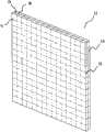
图3是本发明的一种形式的超材料片层的结构示意图。Fig. 3 is a structural schematic diagram of a metamaterial sheet in one form of the present invention.
具体实施方式Detailed ways
如图1至图3所示,根据本发明平板透镜100包括设置在馈源1前方的多个厚度相同的超材料片层11,所述超材料片层包括片状的基材13以及设置在基材13上的多个人造微结构12,所述超材料片层的折射率nk(r)分布满足如下公式:As shown in FIGS. 1 to 3 , according to the present invention, the
nk(r)=nmax-mod(P,λ)/d;(1)nk (r) = nmax - mod (P, λ)/d; (1)
其中,nk(r)表示第k层超材料片层上半径为r处的折射率值;Wherein, nk (r) represents the refractive index value at the radius r on the kth layer of metamaterial sheet;
l为馈源到第1层超材料片层的距离;l is the distance from the feed source to the first layer of metamaterial sheet;
d为平板透镜的厚度;d is the thickness of the flat lens;
d0为超材料片层的厚度;d0 is the thickness of the metamaterial sheet;
nmax表示第1层超材料片层的折射率最大值,即第1层超材料片层中心点O处的折射率值;nmax represents the maximum value of the refractive index of the first layer of metamaterial sheet, that is, the value of the refractive index at the center point O of the first layer of metamaterial sheet;
mod表示取余。其运算为公知常识,mod(A,B)=A-(A div B)*B(div含义为整除,A div B表示,A除以B得到的数的整数位),所以mod(P,λ)=P-(P divλ)*λ。mod means taking the remainder. Its operation is common knowledge, mod(A, B)=A-(A div B)*B (div means integer division, A div B means, the integer digit of the number obtained by dividing A by B), so mod(P, λ)=P-(P div λ)*λ.
d/d0即为超材料片层的层数。即上式的k为大于等于1小于等于d/d0的整数。d/d0 is the number of layers of the metamaterial sheet. That is, k in the above formula is an integer greater than or equal to 1 and less than or equal to d/d0.
l为馈源到第1层超材料片层的距离,即平板透镜的焦距,在设计特定频率的透镜天线时,λ、l与d0均为定值,变量是r,nmax,d。l is the distance from the feed source to the first metamaterial sheet, that is, the focal length of the flat plate lens. When designing a lens antenna with a specific frequency, λ, l andd0 are all fixed values, and the variables are r, nmax , d.
当k=1时,第1层超材料片层的折射率分布为:When k=1, the refractive index distribution of the first layer of metamaterial sheet is:
n1(r)=nmax-mod(P,λ)/d (3);n1 (r) = nmax - mod (P, λ)/d (3);
将(5)式代入(3)式,取得了n1(r)关于r的函数,若我们给定第1层超材料片层的最大值nmax与最小值nmin,例如nmax可以是6,nmin是1,将这两点代入公式(3),即可得到d,这样,n1(r)只有r是变量,即得到了第1超材料片层的折射率分布。通过k=d/d0得到超材料片层的层数,并可依此类推得到其它超材料片层的折射率分布。从而实现位于焦点处的馈源发出的电磁波通过平板透镜100后能够平行出射,反过来,平行入射的电磁波通过平板透镜100能够聚焦到馈源处。Substituting equation (5) into equation (3), the function of n1(r) with respect to r is obtained. If we give the maximum value nmax and the minimum value nmin of the first layer of metamaterial sheet, for example, nmax can be 6 , nmin is 1, and substituting these two points into formula (3), d can be obtained. In this way, only r is a variable in n1 (r), that is, the refractive index distribution of the first metamaterial sheet is obtained. The number of layers of the metamaterial sheet is obtained by k=d/d0 , and the refractive index distribution of other metamaterial sheets can be obtained by analogy. In this way, the electromagnetic wave emitted by the feed source located at the focal point can be emitted in parallel after passing through the
本发明中,馈源1设置在平板透镜的中轴线上,即馈源与超材料片层11的中心的连线与平板透镜的中轴线重合。馈源1与平板透镜100均有支架支撑,图中并未出支架,其不是本发明的核心,采用传统的支撑方式即可。另外馈源优选为喇叭天线。In the present invention, the
如图1至图3所示,所述平板透镜100包括多个厚度相同的超材料片层11。多个超材料片层11紧密贴合,相互之间可以通过双面胶粘接,或者通过螺栓等固定连接。另外,超材料片层11还包括填充层15,填充层15可以空气,也可以是其它介质板,优选为与基材13相同的材料制成的板状件。每一超材料片层11的基材13可以划分为多个相同超材料单元D,每一超材料单元D由一个人造微结构12、单元基材V及单元填充层W构成,每一超材料片层11在厚度方向上只有一个超材料单元D。每一超材料单元D可以是完全相同的方块,可以是立方体,也可是长方体,每一超材料单元D的长、宽、高几何尺寸不大于入射电磁波波长的五分之一(通常为入射电磁波波长的十分之一),以使得整个平板透镜对电磁波具有连续的电场和/或磁场响应。优选情况下,所述超材料单元D为边长是入射电磁波波长十分之一的立方体。当然,填充层的厚度是可以调节的,其最小值可以至0,也就是说不需要填充层,此种情况下,基材与人造微结构组成超材料单元,即此时超材料单元D的厚度等于单元基材V的厚度加上人造微结构的厚度,但是此时,超材料单元D的厚度也要满足十分之一波长的要求,因此,实际上,在超材料单元D的厚度选定在十分之一波长的情况下,单元基材V的厚度越大,则单元填充层W的厚度越小,当然最优的情况下,即是如图2所示的情况,即单元基材V的厚度等于单元填充层W的厚度,且元单元基材V的材料与填充层W的相同。As shown in FIGS. 1 to 3 , the
图3所示的超材料片层11为方形,但是根据需要也可以是圆形或椭圆形等形状,圆形可以是直接在图3所示的方形中截出一个圆形,因为方形四个角处的电磁波能量很弱,这样既不会降低天线的性能,也可以节省材料,降低成本,减小体积及重量。The
作为一种实施例,所述超材料片层11的总厚度为0.818mm,其中填充层与基材的厚度均为0.4mm,人造微结构的厚度为0.018mm。As an example, the total thickness of the
本发明的人造微结构12优选为金属微结构,所述金属微结构由一条或多条金属线组成。金属线本身具有一定的宽度及厚度。本发明的金属微结构优选为具有各向同性的电磁参数的金属微结构,如图2所述的平面雪花状的金属微结构。The
对于具有平面结构的人造微结构,各向同性,是指对于在该二维平面上以任一角度入射的任一电磁波,上述人造微结构在该平面上的电场响应和磁场响应均相同,也即介电常数和磁导率相同;对于具有三维结构的人造微结构,各向同性是指对于在三维空间的任一方向上入射的电磁波,每个上述人造微结构在三维空间上的电场响应和磁场响应均相同。当人造微结构为90度旋转对称结构时,人造微结构即具有各向同性的特征。For artificial microstructures with a planar structure, isotropy means that for any electromagnetic wave incident on the two-dimensional plane at any angle, the electric field response and magnetic field response of the artificial microstructure on the plane are the same, and That is, the permittivity and permeability are the same; for artificial microstructures with three-dimensional structures, isotropy refers to the electric field response and The magnetic field response is the same for all. When the artificial microstructure is a 90-degree rotationally symmetrical structure, the artificial microstructure has isotropic characteristics.
对于二维平面结构,90度旋转对称是指其在该平面上绕一垂直于该平面且过其对称中心的旋转轴任意旋转90度后与原结构重合;对于三维结构,如果具有两两垂直且共交点(交点为旋转中心)的3条旋转轴,使得该结构绕任一旋转轴旋转90度后均与原结构重合或者与原结构以一分界面对称,则该结构为90度旋转对称结构。For a two-dimensional planar structure, 90-degree rotational symmetry means that it coincides with the original structure after being arbitrarily rotated 90 degrees on the plane around a rotation axis perpendicular to the plane and passing through its center of symmetry; for a three-dimensional structure, if there are two perpendicular And there are three rotation axes at the same intersection point (the intersection point is the center of rotation), so that after the structure is rotated 90 degrees around any rotation axis, it will coincide with the original structure or be symmetrical with the original structure at an interface, then the structure is 90-degree rotational symmetry structure.
图2所示的平面雪花状的金属微结构即为各向同性的人造微结构的一种形式,所述的雪花状的金属微结构具有相互垂直平分的第一金属线121及第二金属线122,所述第一金属线121两端连接有相同长度的两个第一金属分支1211,所述第一金属线121两端连接在两个第一金属分支1211的中点上,所述第二金属线122两端连接有相同长度的两个第二金属分支1221,所述第二金属线122两端连接在两个第二金属分支1221的中点上。The plane snowflake-like metal microstructure shown in Figure 2 is a form of isotropic artificial microstructure, and the described snowflake-like metal microstructure has a
另外,从公式(1),我们可以知道,r为超材料片层上任一点距超材料自片层中心轴线的距离,同一个r值有多个点,将这些点连接起来,则构成一个圆,由此,可以知道,每一超材料片层的折射率呈圆形分布,相同半径(同一r值)的超材料单元具有相同的折射率,因此,我们可以使得,同一超材料片层11上的所有人造微结构12具有相同的几何形状,且在基材13上呈圆形排布,靠近圆心处的人造微结构12几何尺寸最大,相同半径处的人造微结构几何尺寸相同,这样设计,即可得到圆形的折射率分布。In addition, from the formula (1), we can know that r is the distance from any point on the metamaterial sheet to the central axis of the metamaterial sheet, and there are multiple points with the same r value, and connecting these points forms a circle , thus, it can be known that the refractive index of each metamaterial sheet is circularly distributed, and the metamaterial units with the same radius (same r value) have the same refractive index, therefore, we can make the
已知折射率其中μ为相对磁导率,ε为相对介电常数,μ与ε合称为电磁参数。实验证明,电磁波通过折射率非均匀的介质材料时,会向折射率大的方向偏折(向折射率大的超材料单元偏折)。在相对磁导率一定的情况下(通常为1),折射率只与介电常数有关,利用只对电场响应的人造微结构可以实现超材料单元折射率的任意值(在一定范围内),在该透镜天线工作频率下,通过仿真获得某一特定形状的人造微结构(如图2所示的平面雪花状的金属微结构)的介电常数随着几何尺寸变化折射率变化的情况,即可列出一一对应的数据,即可设计出我们需要的特定折射率分布的平板透镜。known refractive index Among them, μ is the relative magnetic permeability, ε is the relative permittivity, and μ and ε are collectively called electromagnetic parameters. Experiments have proved that when electromagnetic waves pass through a dielectric material with a non-uniform refractive index, they will be deflected toward a direction with a large refractive index (towards a metamaterial unit with a large refractive index). In the case of a certain relative magnetic permeability (usually 1), the refractive index is only related to the permittivity, and the artificial microstructure that only responds to the electric field can realize any value of the refractive index of the metamaterial unit (within a certain range), Under the operating frequency of the lens antenna, the dielectric constant of an artificial microstructure of a specific shape (such as the planar snowflake-shaped metal microstructure shown in Figure 2) changes with the geometric size of the refractive index through simulation, that is, The one-to-one correspondence data can be listed, and the flat lens with the specific refractive index distribution we need can be designed.
本发明中,所述平板透镜的基材由陶瓷材料、高分子材料、铁电材料、铁氧材料或铁磁材料等制得。高分子材料可选用的有聚四氟乙烯、环氧树脂、F4B复合材料、FR-4复合材料等。例如,聚四氟乙烯的电绝缘性非常好,因此不会对电磁波的电场产生干扰,并且具有优良的化学稳定性、耐腐蚀性,使用寿命长。In the present invention, the base material of the flat lens is made of ceramic material, polymer material, ferroelectric material, ferrite material or ferromagnetic material. Polymer materials can be selected from polytetrafluoroethylene, epoxy resin, F4B composite material, FR-4 composite material, etc. For example, polytetrafluoroethylene has very good electrical insulation, so it will not interfere with the electric field of electromagnetic waves, and has excellent chemical stability, corrosion resistance, and long service life.
本发明中,所述金属微结构为铜线或银线等金属线。上述的金属线可以通过蚀刻、电镀、钻刻、光刻、电子刻或离子刻的方法附着在基材上。当然,也可以采用三维的激光加工工艺。In the present invention, the metal microstructure is metal wires such as copper wires or silver wires. The above metal wires can be attached to the substrate by etching, electroplating, drilling, photolithography, electron etching or ion etching. Of course, three-dimensional laser processing technology can also be used.
另外,如图1所示,本发明还提供本发明还提供了一种透镜天线,包括馈源以及上述的平板透镜,所述平板透镜设置在馈源的前方。In addition, as shown in FIG. 1 , the present invention also provides a lens antenna, which includes a feed source and the above-mentioned flat plate lens, and the flat plate lens is arranged in front of the feed source.
馈源为现有的技术,此处不再述说。The feed source is an existing technology and will not be described here.
上面结合附图对本发明的实施例进行了描述,但是本发明并不局限于上述的具体实施方式,上述的具体实施方式仅仅是示意性的,而不是限制性的,本领域的普通技术人员在本发明的启示下,在不脱离本发明宗旨和权利要求所保护的范围情况下,还可做出很多形式,这些均属于本发明的保护之内。Embodiments of the present invention have been described above in conjunction with the accompanying drawings, but the present invention is not limited to the above-mentioned specific implementations, and the above-mentioned specific implementations are only illustrative, rather than restrictive, and those of ordinary skill in the art will Under the enlightenment of the present invention, many forms can also be made without departing from the gist of the present invention and the protection scope of the claims, and these all belong to the protection of the present invention.
Claims (10)
Priority Applications (1)
| Application Number | Priority Date | Filing Date | Title |
|---|---|---|---|
| CN201110333656.1ACN103094701B (en) | 2011-10-28 | 2011-10-28 | A kind of flat-plate lens and there is the lens antenna of these lens |
Applications Claiming Priority (1)
| Application Number | Priority Date | Filing Date | Title |
|---|---|---|---|
| CN201110333656.1ACN103094701B (en) | 2011-10-28 | 2011-10-28 | A kind of flat-plate lens and there is the lens antenna of these lens |
Publications (2)
| Publication Number | Publication Date |
|---|---|
| CN103094701Atrue CN103094701A (en) | 2013-05-08 |
| CN103094701B CN103094701B (en) | 2015-12-16 |
Family
ID=48207008
Family Applications (1)
| Application Number | Title | Priority Date | Filing Date |
|---|---|---|---|
| CN201110333656.1AActiveCN103094701B (en) | 2011-10-28 | 2011-10-28 | A kind of flat-plate lens and there is the lens antenna of these lens |
Country Status (1)
| Country | Link |
|---|---|
| CN (1) | CN103094701B (en) |
Cited By (6)
| Publication number | Priority date | Publication date | Assignee | Title |
|---|---|---|---|---|
| CN104157945A (en)* | 2014-08-14 | 2014-11-19 | 东南大学 | Metamaterial-based graded-refractive-index slab focusing lens |
| CN104600438A (en)* | 2015-01-28 | 2015-05-06 | 清华大学 | Multi-beam antenna array based on sliding hole surface |
| CN104965243A (en)* | 2015-06-16 | 2015-10-07 | 南京大学 | Slab lens for realizing plane wave focusing by adopting metastructure surface |
| CN105742824A (en)* | 2016-04-13 | 2016-07-06 | 中国电子科技集团公司第五十四研究所 | Low-profile lens antenna capable of realizing wide-angle scanning |
| CN109799611A (en)* | 2019-01-29 | 2019-05-24 | 中山大学 | A design method of achromatic metal lens and achromatic metal lens |
| CN111244640A (en)* | 2020-01-19 | 2020-06-05 | 佛山市粤海信通讯有限公司 | A kind of preparation method of cylindrical electromagnetic wave lens |
Families Citing this family (1)
| Publication number | Priority date | Publication date | Assignee | Title |
|---|---|---|---|---|
| US20170310907A1 (en)* | 2016-04-20 | 2017-10-26 | Microsoft Technology Licensing, Llc | Flat lens imaging devices and systems |
Citations (5)
| Publication number | Priority date | Publication date | Assignee | Title |
|---|---|---|---|---|
| CN101345343A (en)* | 2007-07-11 | 2009-01-14 | 西北工业大学 | Dendritic structure left-handed material microstrip antenna in X-band |
| CN101471492A (en)* | 2007-12-28 | 2009-07-01 | 西北工业大学 | X waveband omnidirectional microstrip antenna with dendritic structure shield-hand material substrate |
| CN101699659A (en)* | 2009-11-04 | 2010-04-28 | 东南大学 | Lens antenna |
| CN201450116U (en)* | 2009-07-01 | 2010-05-05 | 东南大学 | Lens antenna with high frequency bandwidth gain and good directivity |
| CN102057536A (en)* | 2008-04-04 | 2011-05-11 | 雷斯潘公司 | Single-feed multi-cell metamaterial antenna devices |
- 2011
- 2011-10-28CNCN201110333656.1Apatent/CN103094701B/enactiveActive
Patent Citations (5)
| Publication number | Priority date | Publication date | Assignee | Title |
|---|---|---|---|---|
| CN101345343A (en)* | 2007-07-11 | 2009-01-14 | 西北工业大学 | Dendritic structure left-handed material microstrip antenna in X-band |
| CN101471492A (en)* | 2007-12-28 | 2009-07-01 | 西北工业大学 | X waveband omnidirectional microstrip antenna with dendritic structure shield-hand material substrate |
| CN102057536A (en)* | 2008-04-04 | 2011-05-11 | 雷斯潘公司 | Single-feed multi-cell metamaterial antenna devices |
| CN201450116U (en)* | 2009-07-01 | 2010-05-05 | 东南大学 | Lens antenna with high frequency bandwidth gain and good directivity |
| CN101699659A (en)* | 2009-11-04 | 2010-04-28 | 东南大学 | Lens antenna |
Cited By (7)
| Publication number | Priority date | Publication date | Assignee | Title |
|---|---|---|---|---|
| CN104157945A (en)* | 2014-08-14 | 2014-11-19 | 东南大学 | Metamaterial-based graded-refractive-index slab focusing lens |
| CN104600438A (en)* | 2015-01-28 | 2015-05-06 | 清华大学 | Multi-beam antenna array based on sliding hole surface |
| CN104600438B (en)* | 2015-01-28 | 2017-04-19 | 清华大学 | Multi-beam antenna array based on sliding hole surface |
| CN104965243A (en)* | 2015-06-16 | 2015-10-07 | 南京大学 | Slab lens for realizing plane wave focusing by adopting metastructure surface |
| CN105742824A (en)* | 2016-04-13 | 2016-07-06 | 中国电子科技集团公司第五十四研究所 | Low-profile lens antenna capable of realizing wide-angle scanning |
| CN109799611A (en)* | 2019-01-29 | 2019-05-24 | 中山大学 | A design method of achromatic metal lens and achromatic metal lens |
| CN111244640A (en)* | 2020-01-19 | 2020-06-05 | 佛山市粤海信通讯有限公司 | A kind of preparation method of cylindrical electromagnetic wave lens |
Also Published As
| Publication number | Publication date |
|---|---|
| CN103094701B (en) | 2015-12-16 |
Similar Documents
| Publication | Publication Date | Title |
|---|---|---|
| CN103036066B (en) | A kind of Luneberg lens antenna | |
| CN103036046B (en) | A kind of feedback type satellite tv antenna and satellite television receiving system thereof | |
| CN103094701B (en) | A kind of flat-plate lens and there is the lens antenna of these lens | |
| CN202231160U (en) | Antenna based on metamaterial | |
| CN102544745A (en) | Hybrid transmission-reflection microwave antenna | |
| CN102480062B (en) | Antenna based on metamaterials | |
| CN102593611B (en) | Point focusing flat lens antenna | |
| CN102800995B (en) | A metamaterial antenna | |
| CN102780096A (en) | Metamaterial lens antenna | |
| CN102800994B (en) | Cassegrain type metamaterial antenna | |
| CN102480027B (en) | Offset-feed type satellite television antenna and satellite television receiving system thereof | |
| CN102480019A (en) | Metamaterial antenna | |
| CN102480040B (en) | Offset-feed type satellite television antenna and satellite television receiving system thereof | |
| CN103094711B (en) | A kind of lens antenna | |
| CN103094705B (en) | Lens antenna based on Meta Materials | |
| CN103036064B (en) | A kind of Cassegrain metamaterial antenna | |
| CN103367906B (en) | Directional spreading antenna housing and directional antenna system | |
| CN103036065B (en) | A kind of Cassegrain metamaterial antenna | |
| CN102544741B (en) | Microwave antenna | |
| CN102480041A (en) | Feed-forward type satellite television antenna and satellite television receiving system thereof | |
| CN102810767B (en) | Super material microwave antenna taking the super material of class spheroid shape as subreflector | |
| CN102790278A (en) | Directional antenna | |
| CN103094712B (en) | Lens antenna based on metamaterial | |
| CN102480042B (en) | Feed-forward type satellite television antenna and satellite television receiving system thereof | |
| CN102709709B (en) | metamaterial antenna |
Legal Events
| Date | Code | Title | Description |
|---|---|---|---|
| C06 | Publication | ||
| PB01 | Publication | ||
| C10 | Entry into substantive examination | ||
| SE01 | Entry into force of request for substantive examination | ||
| C14 | Grant of patent or utility model | ||
| GR01 | Patent grant |