CN103082996A - Method and apparatus for performing optical imaging by using frequency-domain interferometry - Google Patents
Method and apparatus for performing optical imaging by using frequency-domain interferometryDownload PDFInfo
- Publication number
- CN103082996A CN103082996ACN2013100269850ACN201310026985ACN103082996ACN 103082996 ACN103082996 ACN 103082996ACN 2013100269850 ACN2013100269850 ACN 2013100269850ACN 201310026985 ACN201310026985 ACN 201310026985ACN 103082996 ACN103082996 ACN 103082996A
- Authority
- CN
- China
- Prior art keywords
- frequency
- radiation
- signal
- sample
- electromagnetic radiation
- Prior art date
- Legal status (The legal status is an assumption and is not a legal conclusion. Google has not performed a legal analysis and makes no representation as to the accuracy of the status listed.)
- Pending
Links
Images


Classifications
- G—PHYSICS
- G01—MEASURING; TESTING
- G01J—MEASUREMENT OF INTENSITY, VELOCITY, SPECTRAL CONTENT, POLARISATION, PHASE OR PULSE CHARACTERISTICS OF INFRARED, VISIBLE OR ULTRAVIOLET LIGHT; COLORIMETRY; RADIATION PYROMETRY
- G01J9/00—Measuring optical phase difference; Determining degree of coherence; Measuring optical wavelength
- G01J9/02—Measuring optical phase difference; Determining degree of coherence; Measuring optical wavelength by interferometric methods
- H—ELECTRICITY
- H01—ELECTRIC ELEMENTS
- H01S—DEVICES USING THE PROCESS OF LIGHT AMPLIFICATION BY STIMULATED EMISSION OF RADIATION [LASER] TO AMPLIFY OR GENERATE LIGHT; DEVICES USING STIMULATED EMISSION OF ELECTROMAGNETIC RADIATION IN WAVE RANGES OTHER THAN OPTICAL
- H01S5/00—Semiconductor lasers
- H01S5/50—Amplifier structures not provided for in groups H01S5/02 - H01S5/30
- H01S5/5045—Amplifier structures not provided for in groups H01S5/02 - H01S5/30 the arrangement having a frequency filtering function
- A—HUMAN NECESSITIES
- A61—MEDICAL OR VETERINARY SCIENCE; HYGIENE
- A61B—DIAGNOSIS; SURGERY; IDENTIFICATION
- A61B5/00—Measuring for diagnostic purposes; Identification of persons
- A—HUMAN NECESSITIES
- A61—MEDICAL OR VETERINARY SCIENCE; HYGIENE
- A61B—DIAGNOSIS; SURGERY; IDENTIFICATION
- A61B5/00—Measuring for diagnostic purposes; Identification of persons
- A61B5/0059—Measuring for diagnostic purposes; Identification of persons using light, e.g. diagnosis by transillumination, diascopy, fluorescence
- A61B5/0062—Arrangements for scanning
- A61B5/0066—Optical coherence imaging
- G—PHYSICS
- G01—MEASURING; TESTING
- G01B—MEASURING LENGTH, THICKNESS OR SIMILAR LINEAR DIMENSIONS; MEASURING ANGLES; MEASURING AREAS; MEASURING IRREGULARITIES OF SURFACES OR CONTOURS
- G01B9/00—Measuring instruments characterised by the use of optical techniques
- G01B9/02—Interferometers
- G—PHYSICS
- G01—MEASURING; TESTING
- G01B—MEASURING LENGTH, THICKNESS OR SIMILAR LINEAR DIMENSIONS; MEASURING ANGLES; MEASURING AREAS; MEASURING IRREGULARITIES OF SURFACES OR CONTOURS
- G01B9/00—Measuring instruments characterised by the use of optical techniques
- G01B9/02—Interferometers
- G01B9/02001—Interferometers characterised by controlling or generating intrinsic radiation properties
- G01B9/02002—Interferometers characterised by controlling or generating intrinsic radiation properties using two or more frequencies
- G01B9/02004—Interferometers characterised by controlling or generating intrinsic radiation properties using two or more frequencies using frequency scans
- G—PHYSICS
- G01—MEASURING; TESTING
- G01B—MEASURING LENGTH, THICKNESS OR SIMILAR LINEAR DIMENSIONS; MEASURING ANGLES; MEASURING AREAS; MEASURING IRREGULARITIES OF SURFACES OR CONTOURS
- G01B9/00—Measuring instruments characterised by the use of optical techniques
- G01B9/02—Interferometers
- G01B9/02041—Interferometers characterised by particular imaging or detection techniques
- G01B9/02043—Imaging of the Fourier or pupil or back focal plane, i.e. angle resolved imaging
- G—PHYSICS
- G01—MEASURING; TESTING
- G01B—MEASURING LENGTH, THICKNESS OR SIMILAR LINEAR DIMENSIONS; MEASURING ANGLES; MEASURING AREAS; MEASURING IRREGULARITIES OF SURFACES OR CONTOURS
- G01B9/00—Measuring instruments characterised by the use of optical techniques
- G01B9/02—Interferometers
- G01B9/02055—Reduction or prevention of errors; Testing; Calibration
- G01B9/02075—Reduction or prevention of errors; Testing; Calibration of particular errors
- G01B9/02078—Caused by ambiguity
- G01B9/02079—Quadrature detection, i.e. detecting relatively phase-shifted signals
- G01B9/02081—Quadrature detection, i.e. detecting relatively phase-shifted signals simultaneous quadrature detection, e.g. by spatial phase shifting
- G—PHYSICS
- G01—MEASURING; TESTING
- G01B—MEASURING LENGTH, THICKNESS OR SIMILAR LINEAR DIMENSIONS; MEASURING ANGLES; MEASURING AREAS; MEASURING IRREGULARITIES OF SURFACES OR CONTOURS
- G01B9/00—Measuring instruments characterised by the use of optical techniques
- G01B9/02—Interferometers
- G01B9/02083—Interferometers characterised by particular signal processing and presentation
- G01B9/02084—Processing in the Fourier or frequency domain when not imaged in the frequency domain
- G—PHYSICS
- G01—MEASURING; TESTING
- G01B—MEASURING LENGTH, THICKNESS OR SIMILAR LINEAR DIMENSIONS; MEASURING ANGLES; MEASURING AREAS; MEASURING IRREGULARITIES OF SURFACES OR CONTOURS
- G01B9/00—Measuring instruments characterised by the use of optical techniques
- G01B9/02—Interferometers
- G01B9/0209—Low-coherence interferometers
- G01B9/02091—Tomographic interferometers, e.g. based on optical coherence
- G—PHYSICS
- G01—MEASURING; TESTING
- G01J—MEASUREMENT OF INTENSITY, VELOCITY, SPECTRAL CONTENT, POLARISATION, PHASE OR PULSE CHARACTERISTICS OF INFRARED, VISIBLE OR ULTRAVIOLET LIGHT; COLORIMETRY; RADIATION PYROMETRY
- G01J3/00—Spectrometry; Spectrophotometry; Monochromators; Measuring colours
- G01J3/02—Details
- G01J3/0205—Optical elements not provided otherwise, e.g. optical manifolds, diffusers, windows
- G01J3/0208—Optical elements not provided otherwise, e.g. optical manifolds, diffusers, windows using focussing or collimating elements, e.g. lenses or mirrors; performing aberration correction
- G—PHYSICS
- G01—MEASURING; TESTING
- G01J—MEASUREMENT OF INTENSITY, VELOCITY, SPECTRAL CONTENT, POLARISATION, PHASE OR PULSE CHARACTERISTICS OF INFRARED, VISIBLE OR ULTRAVIOLET LIGHT; COLORIMETRY; RADIATION PYROMETRY
- G01J3/00—Spectrometry; Spectrophotometry; Monochromators; Measuring colours
- G01J3/02—Details
- G01J3/0205—Optical elements not provided otherwise, e.g. optical manifolds, diffusers, windows
- G01J3/021—Optical elements not provided otherwise, e.g. optical manifolds, diffusers, windows using plane or convex mirrors, parallel phase plates, or particular reflectors
- G—PHYSICS
- G01—MEASURING; TESTING
- G01J—MEASUREMENT OF INTENSITY, VELOCITY, SPECTRAL CONTENT, POLARISATION, PHASE OR PULSE CHARACTERISTICS OF INFRARED, VISIBLE OR ULTRAVIOLET LIGHT; COLORIMETRY; RADIATION PYROMETRY
- G01J3/00—Spectrometry; Spectrophotometry; Monochromators; Measuring colours
- G01J3/02—Details
- G01J3/0205—Optical elements not provided otherwise, e.g. optical manifolds, diffusers, windows
- G01J3/0218—Optical elements not provided otherwise, e.g. optical manifolds, diffusers, windows using optical fibers
- G—PHYSICS
- G01—MEASURING; TESTING
- G01J—MEASUREMENT OF INTENSITY, VELOCITY, SPECTRAL CONTENT, POLARISATION, PHASE OR PULSE CHARACTERISTICS OF INFRARED, VISIBLE OR ULTRAVIOLET LIGHT; COLORIMETRY; RADIATION PYROMETRY
- G01J3/00—Spectrometry; Spectrophotometry; Monochromators; Measuring colours
- G01J3/02—Details
- G01J3/0264—Electrical interface; User interface
- G—PHYSICS
- G01—MEASURING; TESTING
- G01J—MEASUREMENT OF INTENSITY, VELOCITY, SPECTRAL CONTENT, POLARISATION, PHASE OR PULSE CHARACTERISTICS OF INFRARED, VISIBLE OR ULTRAVIOLET LIGHT; COLORIMETRY; RADIATION PYROMETRY
- G01J3/00—Spectrometry; Spectrophotometry; Monochromators; Measuring colours
- G01J3/28—Investigating the spectrum
- G01J3/45—Interferometric spectrometry
- G01J3/453—Interferometric spectrometry by correlation of the amplitudes
- G—PHYSICS
- G01—MEASURING; TESTING
- G01J—MEASUREMENT OF INTENSITY, VELOCITY, SPECTRAL CONTENT, POLARISATION, PHASE OR PULSE CHARACTERISTICS OF INFRARED, VISIBLE OR ULTRAVIOLET LIGHT; COLORIMETRY; RADIATION PYROMETRY
- G01J9/00—Measuring optical phase difference; Determining degree of coherence; Measuring optical wavelength
- G—PHYSICS
- G01—MEASURING; TESTING
- G01N—INVESTIGATING OR ANALYSING MATERIALS BY DETERMINING THEIR CHEMICAL OR PHYSICAL PROPERTIES
- G01N21/00—Investigating or analysing materials by the use of optical means, i.e. using sub-millimetre waves, infrared, visible or ultraviolet light
- G01N21/17—Systems in which incident light is modified in accordance with the properties of the material investigated
- G01N21/47—Scattering, i.e. diffuse reflection
- G01N21/4795—Scattering, i.e. diffuse reflection spatially resolved investigating of object in scattering medium
- G—PHYSICS
- G02—OPTICS
- G02B—OPTICAL ELEMENTS, SYSTEMS OR APPARATUS
- G02B26/00—Optical devices or arrangements for the control of light using movable or deformable optical elements
- G02B26/08—Optical devices or arrangements for the control of light using movable or deformable optical elements for controlling the direction of light
- G02B26/10—Scanning systems
- G02B26/12—Scanning systems using multifaceted mirrors
- G—PHYSICS
- G02—OPTICS
- G02B—OPTICAL ELEMENTS, SYSTEMS OR APPARATUS
- G02B27/00—Optical systems or apparatus not provided for by any of the groups G02B1/00 - G02B26/00, G02B30/00
- G02B27/48—Laser speckle optics
- G—PHYSICS
- G02—OPTICS
- G02B—OPTICAL ELEMENTS, SYSTEMS OR APPARATUS
- G02B6/00—Light guides; Structural details of arrangements comprising light guides and other optical elements, e.g. couplings
- G02B6/24—Coupling light guides
- G02B6/36—Mechanical coupling means
- G02B6/3604—Rotary joints allowing relative rotational movement between opposing fibre or fibre bundle ends
- G—PHYSICS
- G02—OPTICS
- G02F—OPTICAL DEVICES OR ARRANGEMENTS FOR THE CONTROL OF LIGHT BY MODIFICATION OF THE OPTICAL PROPERTIES OF THE MEDIA OF THE ELEMENTS INVOLVED THEREIN; NON-LINEAR OPTICS; FREQUENCY-CHANGING OF LIGHT; OPTICAL LOGIC ELEMENTS; OPTICAL ANALOGUE/DIGITAL CONVERTERS
- G02F1/00—Devices or arrangements for the control of the intensity, colour, phase, polarisation or direction of light arriving from an independent light source, e.g. switching, gating or modulating; Non-linear optics
- G02F1/01—Devices or arrangements for the control of the intensity, colour, phase, polarisation or direction of light arriving from an independent light source, e.g. switching, gating or modulating; Non-linear optics for the control of the intensity, phase, polarisation or colour
- G02F1/09—Devices or arrangements for the control of the intensity, colour, phase, polarisation or direction of light arriving from an independent light source, e.g. switching, gating or modulating; Non-linear optics for the control of the intensity, phase, polarisation or colour based on magneto-optical elements, e.g. exhibiting Faraday effect
- G02F1/093—Devices or arrangements for the control of the intensity, colour, phase, polarisation or direction of light arriving from an independent light source, e.g. switching, gating or modulating; Non-linear optics for the control of the intensity, phase, polarisation or colour based on magneto-optical elements, e.g. exhibiting Faraday effect used as non-reciprocal devices, e.g. optical isolators, circulators
- G—PHYSICS
- G02—OPTICS
- G02F—OPTICAL DEVICES OR ARRANGEMENTS FOR THE CONTROL OF LIGHT BY MODIFICATION OF THE OPTICAL PROPERTIES OF THE MEDIA OF THE ELEMENTS INVOLVED THEREIN; NON-LINEAR OPTICS; FREQUENCY-CHANGING OF LIGHT; OPTICAL LOGIC ELEMENTS; OPTICAL ANALOGUE/DIGITAL CONVERTERS
- G02F1/00—Devices or arrangements for the control of the intensity, colour, phase, polarisation or direction of light arriving from an independent light source, e.g. switching, gating or modulating; Non-linear optics
- G02F1/01—Devices or arrangements for the control of the intensity, colour, phase, polarisation or direction of light arriving from an independent light source, e.g. switching, gating or modulating; Non-linear optics for the control of the intensity, phase, polarisation or colour
- G02F1/11—Devices or arrangements for the control of the intensity, colour, phase, polarisation or direction of light arriving from an independent light source, e.g. switching, gating or modulating; Non-linear optics for the control of the intensity, phase, polarisation or colour based on acousto-optical elements, e.g. using variable diffraction by sound or like mechanical waves
- H—ELECTRICITY
- H01—ELECTRIC ELEMENTS
- H01S—DEVICES USING THE PROCESS OF LIGHT AMPLIFICATION BY STIMULATED EMISSION OF RADIATION [LASER] TO AMPLIFY OR GENERATE LIGHT; DEVICES USING STIMULATED EMISSION OF ELECTROMAGNETIC RADIATION IN WAVE RANGES OTHER THAN OPTICAL
- H01S3/00—Lasers, i.e. devices using stimulated emission of electromagnetic radiation in the infrared, visible or ultraviolet wave range
- H01S3/005—Optical devices external to the laser cavity, specially adapted for lasers, e.g. for homogenisation of the beam or for manipulating laser pulses, e.g. pulse shaping
- H01S3/0071—Beam steering, e.g. whereby a mirror outside the cavity is present to change the beam direction
- H—ELECTRICITY
- H01—ELECTRIC ELEMENTS
- H01S—DEVICES USING THE PROCESS OF LIGHT AMPLIFICATION BY STIMULATED EMISSION OF RADIATION [LASER] TO AMPLIFY OR GENERATE LIGHT; DEVICES USING STIMULATED EMISSION OF ELECTROMAGNETIC RADIATION IN WAVE RANGES OTHER THAN OPTICAL
- H01S3/00—Lasers, i.e. devices using stimulated emission of electromagnetic radiation in the infrared, visible or ultraviolet wave range
- H01S3/005—Optical devices external to the laser cavity, specially adapted for lasers, e.g. for homogenisation of the beam or for manipulating laser pulses, e.g. pulse shaping
- H01S3/0078—Frequency filtering
- H—ELECTRICITY
- H01—ELECTRIC ELEMENTS
- H01S—DEVICES USING THE PROCESS OF LIGHT AMPLIFICATION BY STIMULATED EMISSION OF RADIATION [LASER] TO AMPLIFY OR GENERATE LIGHT; DEVICES USING STIMULATED EMISSION OF ELECTROMAGNETIC RADIATION IN WAVE RANGES OTHER THAN OPTICAL
- H01S5/00—Semiconductor lasers
- H01S5/005—Optical components external to the laser cavity, specially adapted therefor, e.g. for homogenisation or merging of the beams or for manipulating laser pulses, e.g. pulse shaping
- H01S5/0071—Optical components external to the laser cavity, specially adapted therefor, e.g. for homogenisation or merging of the beams or for manipulating laser pulses, e.g. pulse shaping for beam steering, e.g. using a mirror outside the cavity to change the beam direction
- H—ELECTRICITY
- H01—ELECTRIC ELEMENTS
- H01S—DEVICES USING THE PROCESS OF LIGHT AMPLIFICATION BY STIMULATED EMISSION OF RADIATION [LASER] TO AMPLIFY OR GENERATE LIGHT; DEVICES USING STIMULATED EMISSION OF ELECTROMAGNETIC RADIATION IN WAVE RANGES OTHER THAN OPTICAL
- H01S5/00—Semiconductor lasers
- H01S5/005—Optical components external to the laser cavity, specially adapted therefor, e.g. for homogenisation or merging of the beams or for manipulating laser pulses, e.g. pulse shaping
- H01S5/0078—Optical components external to the laser cavity, specially adapted therefor, e.g. for homogenisation or merging of the beams or for manipulating laser pulses, e.g. pulse shaping for frequency filtering
- H—ELECTRICITY
- H01—ELECTRIC ELEMENTS
- H01S—DEVICES USING THE PROCESS OF LIGHT AMPLIFICATION BY STIMULATED EMISSION OF RADIATION [LASER] TO AMPLIFY OR GENERATE LIGHT; DEVICES USING STIMULATED EMISSION OF ELECTROMAGNETIC RADIATION IN WAVE RANGES OTHER THAN OPTICAL
- H01S5/00—Semiconductor lasers
- H01S5/10—Construction or shape of the optical resonator, e.g. extended or external cavity, coupled cavities, bent-guide, varying width, thickness or composition of the active region
- H01S5/1025—Extended cavities
- H—ELECTRICITY
- H01—ELECTRIC ELEMENTS
- H01S—DEVICES USING THE PROCESS OF LIGHT AMPLIFICATION BY STIMULATED EMISSION OF RADIATION [LASER] TO AMPLIFY OR GENERATE LIGHT; DEVICES USING STIMULATED EMISSION OF ELECTROMAGNETIC RADIATION IN WAVE RANGES OTHER THAN OPTICAL
- H01S5/00—Semiconductor lasers
- H01S5/10—Construction or shape of the optical resonator, e.g. extended or external cavity, coupled cavities, bent-guide, varying width, thickness or composition of the active region
- H01S5/14—External cavity lasers
- A—HUMAN NECESSITIES
- A61—MEDICAL OR VETERINARY SCIENCE; HYGIENE
- A61B—DIAGNOSIS; SURGERY; IDENTIFICATION
- A61B5/00—Measuring for diagnostic purposes; Identification of persons
- A61B5/72—Signal processing specially adapted for physiological signals or for diagnostic purposes
- A61B5/7235—Details of waveform analysis
- A61B5/7253—Details of waveform analysis characterised by using transforms
- A61B5/7257—Details of waveform analysis characterised by using transforms using Fourier transforms
- G—PHYSICS
- G01—MEASURING; TESTING
- G01B—MEASURING LENGTH, THICKNESS OR SIMILAR LINEAR DIMENSIONS; MEASURING ANGLES; MEASURING AREAS; MEASURING IRREGULARITIES OF SURFACES OR CONTOURS
- G01B2290/00—Aspects of interferometers not specifically covered by any group under G01B9/02
- G01B2290/45—Multiple detectors for detecting interferometer signals
- G—PHYSICS
- G01—MEASURING; TESTING
- G01B—MEASURING LENGTH, THICKNESS OR SIMILAR LINEAR DIMENSIONS; MEASURING ANGLES; MEASURING AREAS; MEASURING IRREGULARITIES OF SURFACES OR CONTOURS
- G01B2290/00—Aspects of interferometers not specifically covered by any group under G01B9/02
- G01B2290/70—Using polarization in the interferometer
- G—PHYSICS
- G01—MEASURING; TESTING
- G01J—MEASUREMENT OF INTENSITY, VELOCITY, SPECTRAL CONTENT, POLARISATION, PHASE OR PULSE CHARACTERISTICS OF INFRARED, VISIBLE OR ULTRAVIOLET LIGHT; COLORIMETRY; RADIATION PYROMETRY
- G01J9/00—Measuring optical phase difference; Determining degree of coherence; Measuring optical wavelength
- G01J9/02—Measuring optical phase difference; Determining degree of coherence; Measuring optical wavelength by interferometric methods
- G01J9/0215—Measuring optical phase difference; Determining degree of coherence; Measuring optical wavelength by interferometric methods by shearing interferometric methods
- H—ELECTRICITY
- H01—ELECTRIC ELEMENTS
- H01S—DEVICES USING THE PROCESS OF LIGHT AMPLIFICATION BY STIMULATED EMISSION OF RADIATION [LASER] TO AMPLIFY OR GENERATE LIGHT; DEVICES USING STIMULATED EMISSION OF ELECTROMAGNETIC RADIATION IN WAVE RANGES OTHER THAN OPTICAL
- H01S3/00—Lasers, i.e. devices using stimulated emission of electromagnetic radiation in the infrared, visible or ultraviolet wave range
- H01S3/05—Construction or shape of optical resonators; Accommodation of active medium therein; Shape of active medium
- H01S3/08—Construction or shape of optical resonators or components thereof
- H01S3/08004—Construction or shape of optical resonators or components thereof incorporating a dispersive element, e.g. a prism for wavelength selection
- H01S3/08009—Construction or shape of optical resonators or components thereof incorporating a dispersive element, e.g. a prism for wavelength selection using a diffraction grating
- H—ELECTRICITY
- H01—ELECTRIC ELEMENTS
- H01S—DEVICES USING THE PROCESS OF LIGHT AMPLIFICATION BY STIMULATED EMISSION OF RADIATION [LASER] TO AMPLIFY OR GENERATE LIGHT; DEVICES USING STIMULATED EMISSION OF ELECTROMAGNETIC RADIATION IN WAVE RANGES OTHER THAN OPTICAL
- H01S3/00—Lasers, i.e. devices using stimulated emission of electromagnetic radiation in the infrared, visible or ultraviolet wave range
- H01S3/05—Construction or shape of optical resonators; Accommodation of active medium therein; Shape of active medium
- H01S3/08—Construction or shape of optical resonators or components thereof
- H01S3/08059—Constructional details of the reflector, e.g. shape
- H01S3/08063—Graded reflectivity, e.g. variable reflectivity mirror
- H—ELECTRICITY
- H01—ELECTRIC ELEMENTS
- H01S—DEVICES USING THE PROCESS OF LIGHT AMPLIFICATION BY STIMULATED EMISSION OF RADIATION [LASER] TO AMPLIFY OR GENERATE LIGHT; DEVICES USING STIMULATED EMISSION OF ELECTROMAGNETIC RADIATION IN WAVE RANGES OTHER THAN OPTICAL
- H01S3/00—Lasers, i.e. devices using stimulated emission of electromagnetic radiation in the infrared, visible or ultraviolet wave range
- H01S3/10—Controlling the intensity, frequency, phase, polarisation or direction of the emitted radiation, e.g. switching, gating, modulating or demodulating
- H01S3/105—Controlling the intensity, frequency, phase, polarisation or direction of the emitted radiation, e.g. switching, gating, modulating or demodulating by controlling the mutual position or the reflecting properties of the reflectors of the cavity, e.g. by controlling the cavity length
- H—ELECTRICITY
- H01—ELECTRIC ELEMENTS
- H01S—DEVICES USING THE PROCESS OF LIGHT AMPLIFICATION BY STIMULATED EMISSION OF RADIATION [LASER] TO AMPLIFY OR GENERATE LIGHT; DEVICES USING STIMULATED EMISSION OF ELECTROMAGNETIC RADIATION IN WAVE RANGES OTHER THAN OPTICAL
- H01S3/00—Lasers, i.e. devices using stimulated emission of electromagnetic radiation in the infrared, visible or ultraviolet wave range
- H01S3/10—Controlling the intensity, frequency, phase, polarisation or direction of the emitted radiation, e.g. switching, gating, modulating or demodulating
- H01S3/106—Controlling the intensity, frequency, phase, polarisation or direction of the emitted radiation, e.g. switching, gating, modulating or demodulating by controlling devices placed within the cavity
- H01S3/1068—Controlling the intensity, frequency, phase, polarisation or direction of the emitted radiation, e.g. switching, gating, modulating or demodulating by controlling devices placed within the cavity using an acousto-optical device
- H—ELECTRICITY
- H01—ELECTRIC ELEMENTS
- H01S—DEVICES USING THE PROCESS OF LIGHT AMPLIFICATION BY STIMULATED EMISSION OF RADIATION [LASER] TO AMPLIFY OR GENERATE LIGHT; DEVICES USING STIMULATED EMISSION OF ELECTROMAGNETIC RADIATION IN WAVE RANGES OTHER THAN OPTICAL
- H01S5/00—Semiconductor lasers
- H01S5/10—Construction or shape of the optical resonator, e.g. extended or external cavity, coupled cavities, bent-guide, varying width, thickness or composition of the active region
- H01S5/14—External cavity lasers
- H01S5/141—External cavity lasers using a wavelength selective device, e.g. a grating or etalon
- H—ELECTRICITY
- H01—ELECTRIC ELEMENTS
- H01S—DEVICES USING THE PROCESS OF LIGHT AMPLIFICATION BY STIMULATED EMISSION OF RADIATION [LASER] TO AMPLIFY OR GENERATE LIGHT; DEVICES USING STIMULATED EMISSION OF ELECTROMAGNETIC RADIATION IN WAVE RANGES OTHER THAN OPTICAL
- H01S5/00—Semiconductor lasers
- H01S5/10—Construction or shape of the optical resonator, e.g. extended or external cavity, coupled cavities, bent-guide, varying width, thickness or composition of the active region
- H01S5/14—External cavity lasers
- H01S5/146—External cavity lasers using a fiber as external cavity
Landscapes
- Physics & Mathematics (AREA)
- General Physics & Mathematics (AREA)
- Spectroscopy & Molecular Physics (AREA)
- Health & Medical Sciences (AREA)
- Optics & Photonics (AREA)
- Life Sciences & Earth Sciences (AREA)
- Engineering & Computer Science (AREA)
- Electromagnetism (AREA)
- General Health & Medical Sciences (AREA)
- Nonlinear Science (AREA)
- Pathology (AREA)
- Condensed Matter Physics & Semiconductors (AREA)
- Animal Behavior & Ethology (AREA)
- Veterinary Medicine (AREA)
- Heart & Thoracic Surgery (AREA)
- Public Health (AREA)
- Surgery (AREA)
- Biomedical Technology (AREA)
- Medical Informatics (AREA)
- Molecular Biology (AREA)
- Biophysics (AREA)
- Radiology & Medical Imaging (AREA)
- Nuclear Medicine, Radiotherapy & Molecular Imaging (AREA)
- Signal Processing (AREA)
- Plasma & Fusion (AREA)
- Power Engineering (AREA)
- Analytical Chemistry (AREA)
- Human Computer Interaction (AREA)
- Chemical & Material Sciences (AREA)
- Biochemistry (AREA)
- Immunology (AREA)
- Mathematical Physics (AREA)
- Investigating Or Analysing Materials By Optical Means (AREA)
- Instruments For Measurement Of Length By Optical Means (AREA)
Abstract
Translated fromChinese
Description
Translated fromChinese对相关申请的交叉引用Cross References to Related Applications
本申请是中国专利申请第200480031773.0号(国际申请号为PCT/US2004/029148)的分案申请,其全部内容通过引用合并于此。本申请要求了提交于2003年10月23日的美国临时申请No.60/514,769的优先权,其全部公开通过引用结合于此。This application is a divisional application of Chinese Patent Application No. 200480031773.0 (International Application No. PCT/US2004/029148), the entire contents of which are hereby incorporated by reference. This application claims priority to US Provisional Application No. 60/514,769, filed October 23, 2003, the entire disclosure of which is hereby incorporated by reference.
技术领域technical field
本发明总地涉及光学成像,且更具体地,涉及用于使用频域干涉测量法进行光学成像的方法和设备。The present invention relates generally to optical imaging, and more particularly to methods and apparatus for optical imaging using frequency domain interferometry.
背景技术Background technique
如本领域中所公知的,光学干涉测量反射测量法是一种有力的工具,其用于进行非入侵的、高分辨率(~10μm)的生物学或其它样品的横截面成像,以使诸如反射、吸收、散射、衰减、双折射和光谱分析的微结构的光学特性可视化。存在许多本领域中公知的干涉测量成像技术。这些技术总体而言可划分为两个主要类别:(i)时域技术,和(ii)频域技术。As is well known in the art, optical interferometry reflectometry is a powerful tool for non-invasive, high-resolution (~10 μm) cross-sectional imaging of biological or other samples, such as Visualization of optical properties of microstructures for reflection, absorption, scattering, attenuation, birefringence and spectral analysis. There are many interferometric imaging techniques known in the art. These techniques can generally be divided into two main categories: (i) time domain techniques, and (ii) frequency domain techniques.
低相干干涉测量法(“LCI”)是时域技术之一。此技术使用扫描系统来改变参考臂长度并且在检测器处采集干涉信号。然后,对条纹图案解调以获得源互相关函数的相干包络。光学相干层析成像法(“OCT”)是一种用于使用LCI获得二或三维图像的技术。OCT在授予Swanson等人的美国专利No.5,321,501中描述。已描述了OCT技术的多个变形,但很多遭遇小于最佳的信噪比(“SNR”),导致非最佳的分辨率、低成像帧速率和不良的穿透深度。功率使用是这种成像技术中的一个因素。例如在眼科应用中,在热损坏可发生前,只有特定毫瓦数的功率是可容忍的。因此,在这样的环境中增加SNR,提升功率是不可行的。尽管如此,将值得期望的是,有一种具有优良的SNR而显著增加功率需求的成像方法。Low coherence interferometry ("LCI") is one of the time domain techniques. This technique uses a scanning system to vary the reference arm length and collect the interference signal at the detector. Then, the fringe pattern is demodulated to obtain the coherence envelope of the source cross-correlation function. Optical coherence tomography ("OCT") is a technique for obtaining two- or three-dimensional images using LCI. OCT is described in US Patent No. 5,321,501 to Swanson et al. Several variants of OCT techniques have been described, but many suffer from less than optimal signal-to-noise ratio ("SNR"), resulting in sub-optimal resolution, low imaging frame rates, and poor penetration depth. Power usage is a factor in this imaging technique. In ophthalmic applications, for example, only certain milliwatts of power are tolerable before thermal damage can occur. Therefore, it is not feasible to increase the SNR and increase the power in such an environment. Nonetheless, it would be desirable to have an imaging method with superior SNR that significantly increases power requirements.
不足的SNR亦可阻止以高的帧速率使用OCT技术,高的帧速率对于避免运动假象和克服例如可用于活体内血管成像的短测量时间窗是重要的。因此,期望一种改善SNR和成像速度(例如帧速率)的方法。Insufficient SNR may also prevent the use of OCT techniques at high frame rates, which are important to avoid motion artefacts and to overcome short measurement time windows, eg for in vivo vascular imaging. Therefore, a method of improving SNR and imaging speed (eg, frame rate) is desired.
光谱干涉法或光谱雷达是频域成像技术之一。在光谱雷达中,样品和参考臂光的交叉谱密度的实部用光谱仪测量。深度分布信息可以依据交叉谱密度调制来编码。Spectral interferometry or spectral radar is one of the frequency domain imaging techniques. In spectral radar, the real part of the cross spectral density of sample and reference arm light is measured with a spectrometer. Depth profile information can be encoded in terms of cross-spectral density modulation.
前面已描述了用来增加LCI和OCT的SNR的光谱雷达概念的使用。此技术使用具有大数目的像素(1,000的量级)的电荷耦合器件(“CCD”)以达到毫米量级的扫描范围。CCD器件的快速读出使得高速成像成为可能。The use of the spectral radar concept to increase the SNR of LCI and OCT has been described previously. This technique uses a charge-coupled device ("CCD") with a large number of pixels (on the order of 1,000) to achieve a scan range on the order of millimeters. The fast readout of the CCD device makes high-speed imaging possible.
然而,存在许多与使用CCD器件相关联的缺点。首先,与单元件光电接收器相比,CCD器件相对昂贵。其次,前面描述的方法使用单个CCD来采集数据。由于电荷存储容量是有限的,所以需要将参考臂功率减小到大约与样品臂功率相同的水平,引起了样品臂光上的自相关噪声。另外,由于没有生成载流子,所以在此系统中的噪声中,1/f噪声将起支配作用。第三,即使以现有CCD技术的短的积分时间,干涉计中的相位不稳定性仍减小交叉谱密度调制的条纹可见度。此缺陷使得该技术易受运动假象的影响。However, there are a number of disadvantages associated with the use of CCD devices. First, CCD devices are relatively expensive compared to single-element optoelectronic receivers. Second, the methods described previously use a single CCD to acquire data. Since the charge storage capacity is limited, the reference arm power needs to be reduced to approximately the same level as the sample arm power, causing autocorrelation noise on the sample arm light. Also, since no carriers are generated, 1/f noise will dominate the noise in this system. Third, even with the short integration times of existing CCD technologies, phase instabilities in the interferometer reduce fringe visibility of cross-spectral density modulation. This drawback makes the technique susceptible to motion artifacts.
相干的频率调制的连续波反射测量法(C-FWCW)是本领域中公知的另一频域技术。授予Swanson等人的美国专利No.5,956,355和6,160,826描述了使用此技术的光学成像方法和设备。前面描述的成像方法基于使用连续调谐的单频激光器作为光源。要求调谐波长范围为几十个纳米以实现小于100微米的测距分辩率(ranging resolution)。激光器的瞬时线宽必须小于约0.1nm以实现1.0mm量级的检测范围。调谐速率应大于10kHz以便高速(例如视频速率)成像。虽然外腔式半导体激光器可以配置成在几十个纳米上实现无跳模的单频调谐,但调谐速率由于机械稳定性的严格要求而已小于1Hz。克服此速度困难的方法是优选的。Coherent frequency modulated continuous wave reflectometry (C-FWCW) is another frequency domain technique known in the art. US Patent Nos. 5,956,355 and 6,160,826 to Swanson et al. describe optical imaging methods and apparatus using this technique. The previously described imaging method is based on the use of a continuously tuned single-frequency laser as the light source. A tuning wavelength range of tens of nanometers is required to achieve a ranging resolution of less than 100 microns. The instantaneous linewidth of the laser must be less than about 0.1 nm to achieve a detection range of the order of 1.0 mm. The tuning rate should be greater than 10kHz for high speed (eg video rate) imaging. Although external-cavity diode lasers can be configured to achieve mode-hop-free single-frequency tuning over tens of nanometers, the tuning rate is limited to less than 1 Hz due to stringent requirements for mechanical stability. A method to overcome this speed difficulty is preferred.
因此,将值得期望的是,提供一种克服传统LCI和OCT的源可用性和扫描速度缺陷的系统和方法。Accordingly, it would be desirable to provide a system and method that overcomes the source availability and scan speed limitations of conventional LCI and OCT.
发明内容Contents of the invention
根据本发明示例性的实施例,一种示例性的光学频域成像(“OFDI”)系统可包括多频率模(或多纵向或轴向模)波长扫描激光源(wavelength-swept laser sourse),其光耦合到包含所研究的样品的干涉计。该系统可进一步包括配置成产生从样品反射的光和参考光之间的正交的干涉测量信号的装置以及设置成接收所述干涉测量信号的检测器。According to an exemplary embodiment of the present invention, an exemplary optical frequency domain imaging ("OFDI") system may include a multi-frequency mode (or multi-longitudinal or axial mode) wavelength-swept laser source, It is optically coupled to an interferometer containing the sample under study. The system may further comprise means configured to generate an orthogonal interferometric signal between light reflected from the sample and the reference light and a detector arranged to receive said interferometric signal.
利用这样的示例性的特定装置,可以提供一种OFDI系统,该系统可以以与传统系统的源功率相比相对低的源功率来操作,并且/或者该系统以与传统系统的采集速率相比相对高的采集速率来操作。扫描源的使用导致具有减小的散粒噪声和其它形式的噪声的成像系统,其允许比传统系统低得多的源功率或高得多的采集速率。这可导致增加的检测灵敏度,从而导致提供实时成像的能力。这样的成像速度可帮助胃肠、眼科和动脉成像领域中的从业者,在这些成像领域中,运动假象是持续的问题。通过增加帧速率同时维持或改善信噪比,这样的假象可被最小化或在一些情况下被消除。本发明的示例性的实施例亦可利用OFDI实现对组织的大面积的筛选并且允许实现临床上可行的筛选协议的使用。With such exemplary specific arrangements, it is possible to provide an OFDI system that can operate at a relatively low source power compared to that of conventional systems and/or that can operate at an acquisition rate compared to conventional systems relatively high acquisition rate to operate. The use of a scanned source results in an imaging system with reduced shot noise and other forms of noise, which allows for much lower source power or much higher acquisition rates than conventional systems. This can lead to increased detection sensitivity, leading to the ability to provide real-time imaging. This imaging speed helps practitioners in the fields of gastrointestinal, ophthalmic, and arterial imaging, where motion artifacts are a persistent problem. By increasing the frame rate while maintaining or improving the signal-to-noise ratio, such artifacts can be minimized or in some cases eliminated. Exemplary embodiments of the present invention can also utilize OFDI to enable screening of large areas of tissue and allow the use of clinically feasible screening protocols.
在本发明的一个示例性的实施例中,可以提供波长扫描激光器,其可以在激光腔中使用光学带通扫描滤波器来产生迅速扫描的多频率模式输出。通过在激光腔中使用光学带通扫描滤波器,不必要调谐激光腔长度以提供激光光谱的同步调谐。换言之,不需要以与激光器的中心波长相同的速率来调谐激光器的纵腔模。In an exemplary embodiment of the present invention, a wavelength-swept laser may be provided which may use optical bandpass-swept filters in the laser cavity to produce a rapidly swept multi-frequency mode output. By using optical bandpass scanning filters in the laser cavity, it is not necessary to tune the laser cavity length to provide simultaneous tuning of the laser spectrum. In other words, the longitudinal cavity mode of the laser need not be tuned at the same rate as the center wavelength of the laser.
在本发明的另一示例性的实施例中,检测器可以是双平衡接收器,其设置成接受干涉测量信号并且抑制干涉测量信号中的相对强度噪声。In another exemplary embodiment of the invention, the detector may be a double balanced receiver arranged to accept the interferometric signal and reject relative intensity noise in the interferometric signal.
通过进行傅立叶域中的信号处理,根据本发明的一个示例性实施例的信噪比(“SNR”)的增益优于诸如OCT的时域方法。SNR提高到N倍,N为深度范围与空间分辨率的比。提高倍数N可达到几百至几千。此SNR的增加使得能够成像得快到N倍,或可替换地允许以与具有低到1/N的功率的源相同的速度来成像。结果,本发明的该示例性的实施例克服了传统LCI和OCT的两个重要的缺陷,例如源可用性和扫描速度。因子N可达到大于1,000,并且允许构造OFDI系统,其可以自当前实践中的OCT和LCI技术改进三个数量级以上。By performing signal processing in the Fourier domain, the signal-to-noise ratio ("SNR") gain according to an exemplary embodiment of the present invention is superior to time-domain methods such as OCT. The SNR is increased by a factor of N, where N is the ratio of depth range to spatial resolution. The increase factor N can reach several hundred to several thousand. This increase in SNR enables imaging up to N times faster, or alternatively allows imaging at the same speed as sources with power as low as 1/N. As a result, this exemplary embodiment of the present invention overcomes two important drawbacks of conventional LCI and OCT, such as source availability and scan speed. The factor N can reach greater than 1,000 and allows the construction of OFDI systems that can be improved by more than three orders of magnitude from OCT and LCI techniques in current practice.
实现了SNR的增益是因为,例如,散粒噪声具有白噪声谱。频率ω(或波长λ)处的存在于检测器的信号强度只对频率ω处的信号有贡献,但是散粒噪声在所有频率处生成。通过使每个检测器的光学带宽变窄,可以减小每个频率处的散粒噪声贡献,同时信号成分保持相同。The gain in SNR is achieved because, for example, shot noise has a white noise spectrum. The signal strength present at the detector at frequency ω (or wavelength λ) only contributes to the signal at frequency ω, but shot noise is generated at all frequencies. By narrowing the optical bandwidth of each detector, the shot noise contribution at each frequency can be reduced while the signal content remains the same.
与OCT相比,根据本发明的示例性的实施例改善了当前数据采集速度和源的可用性。散粒噪声归因于电流的统计波动,该统计波动归因于量子化的或离散的电荷。散粒噪声的减小允许低得多的源功率或高得多的采集速率。当前数据采集速率的限制(~4帧/秒)是由可用的源功率和用于扫描延迟的快速机制的可用性而施加的。检测灵敏度的到8倍的增加将允许以约每秒30帧的速度来实时成像。灵敏度的到约1,000-2,000倍的增加允许使用具有低得多的功率和高得多的谱带宽的源,其易于获得、生产较便宜并且可以生成较高分辨率的OFDI图像。Exemplary embodiments according to the present invention improve current data acquisition speed and source availability compared to OCT. Shot noise is due to statistical fluctuations in electrical current due to quantized or discrete charges. The reduction in shot noise allows for much lower source power or much higher acquisition rates. The current data acquisition rate limitation (~4 frames/s) is imposed by the available source power and the availability of fast mechanisms for scanning delays. An 8-fold increase in detection sensitivity would allow real-time imaging at approximately 30 frames per second. The ~1,000-2,000-fold increase in sensitivity allows the use of sources with much lower power and much higher spectral bandwidth that are readily available, cheaper to produce, and can generate higher resolution OFDI images.
针对OFDI的眼科应用,有效的检测优选地允许显著增加采集速度。眼科应用的一个限制是根据ANSI标准允许进入眼睛的功率(在830nm处大约700微瓦)。眼科应用中的当前数据采集速度是每秒大约100-500个A-线。本发明的功率效率高的检测技术将允许每秒约100,000个A-线的量级的A-线采集速率,或以每个图像约3,000个A-线的视频速率成像。For ophthalmic applications of OFDI, efficient detection preferably allows for a significant increase in acquisition speed. One limitation for ophthalmic applications is the power allowed into the eye according to ANSI standards (approximately 700 microwatts at 830nm). Current data acquisition rates in ophthalmic applications are approximately 100-500 A-lines per second. The power efficient detection technique of the present invention will allow A-line acquisition rates on the order of about 100,000 A-lines per second, or imaging at a video rate of about 3,000 A-lines per image.
为了实现至少一些本发明的目的,提供了根据本发明的一个示例性的实施例的设备和方法。具体而言,至少一个第一电磁辐射可以提供给样品,并且至少一个第二电磁辐射可以提供给非反射的参考。第一和/或第二辐射的频率随着时间变化。在关联于第一辐射的至少一个第三辐射与关联于第二辐射的至少一个第四辐射之间检测干涉。可替换地,第一电磁辐射和/或第二电磁辐射具有随着时间变化的谱。所述谱在特定时间处可以包含多个频率。另外,有可能以第一偏振态检测第三辐射与第四辐射之间的干涉信号。此外,可以优选地以不同于第一偏振态的第二偏振态检测第三和第四辐射之间的又一干涉信号。第一和/或第二电磁辐射可以具有中值频率以大于每毫秒100万亿赫兹(Tera Hertz)的调谐速度随时间基本上连续变化的谱。To achieve at least some of the objects of the present invention, an apparatus and method according to an exemplary embodiment of the present invention are provided. In particular, at least one first electromagnetic radiation may be provided to the sample and at least one second electromagnetic radiation may be provided to the non-reflecting reference. The frequency of the first and/or second radiation varies over time. Interference is detected between at least one third radiation associated with the first radiation and at least one fourth radiation associated with the second radiation. Alternatively, the first electromagnetic radiation and/or the second electromagnetic radiation has a spectrum that varies over time. The spectrum may contain multiple frequencies at a particular time. In addition, it is possible to detect an interference signal between the third radiation and the fourth radiation in the first polarization state. Furthermore, a further interference signal between the third and fourth radiation may preferably be detected in a second polarization state different from the first polarization state. The first and/or second electromagnetic radiation may have a spectrum with a median frequency varying substantially continuously over time at a tuning rate greater than 100 Tera Hertz per millisecond.
在本发明的一个示例性的实施例中,第三辐射可以是从样品返回的辐射,并且至少一个第四辐射是从参考返回的辐射。第一、第二、第三和/或第四辐射的频率可以移位。可基于所检测的干涉来生成图像。可以使用探头,其扫描样品的横向位置以生成扫描数据,并且将扫描数据提供给第三装置以便生成图像。扫描数据可以包括在样品上的多个横向位置获得的所检测的干涉。可以使用至少一个光电检测器和至少一个电滤波器,该电滤波器跟随着跟随有电滤波器的光电检测器。电滤波器可以是带通滤波器,其具有大约与通过频移装置的频移的量值相同的中心频率。电滤波器的传输特性(transmission profile)可基本上在其通带上变化。所述探头可包括旋转的接合和光纤导管。该导管可以以高于每秒30转的速度旋转。可以提供至少一个偏振调制器。In an exemplary embodiment of the invention, the third radiation may be radiation returned from the sample and the at least one fourth radiation is radiation returned from the reference. The frequency of the first, second, third and/or fourth radiation may be shifted. An image may be generated based on the detected interference. A probe may be used that scans the lateral position of the sample to generate scan data and provides the scan data to a third device for generating an image. The scan data may include detected interferences obtained at multiple lateral locations on the sample. At least one photodetector followed by a photodetector followed by an electrical filter and at least one electrical filter may be used. The electrical filter may be a bandpass filter having a center frequency of approximately the same magnitude as the frequency shift by the frequency shifting means. The transmission profile of an electrical filter can vary substantially over its passband. The probe may include a rotating joint and a fiber optic guide. The catheter can rotate at speeds greater than 30 revolutions per second. At least one polarization modulator may be provided.
可以使用至少一个偏振分集(polarization diverse)接收和/或偏振分集和双平衡接收器。还有可能跟踪下列相位差:At least one polarization diverse reception and/or polarization diversity and double balanced receivers may be used. It is also possible to track the following phase differences:
·第一电磁辐射和第二电磁辐射之间,和/或between the first electromagnetic radiation and the second electromagnetic radiation, and/or
·第三电磁辐射和第四电磁辐射之间。• Between the third electromagnetic radiation and the fourth electromagnetic radiation.
根据本发明的又另一示例性的实施例,可以发射第一和第二电磁辐射,它们中的至少一个具有中值频率以大于每毫秒100万亿赫兹的调谐速度随时间基本上连续变化的谱。According to yet another exemplary embodiment of the present invention, first and second electromagnetic radiation may be emitted, at least one of which has a median frequency that varies substantially continuously over time at a tuning rate greater than 100 trillion Hertz per millisecond Spectrum.
根据本发明的又一示例性的实施例,提供了一种设备。这样的设备包括至少一个第一装置,其将至少一个第一电磁辐射提供给样品并且将至少一个第二电磁辐射提供给参考。该设备还包括:至少一个第二装置,其适于移位第一电磁辐射和第二电磁辐射的频率;以及干涉计,其将第一和第二电磁辐射干涉以产生干涉信号。此外,该设备包括至少一个第二装置,该装置检测第一和第二电磁辐射之间的干涉。According to yet another exemplary embodiment of the present invention, an apparatus is provided. Such an apparatus comprises at least one first means which provides at least one first electromagnetic radiation to the sample and at least one second electromagnetic radiation to the reference. The device also includes at least one second device adapted to shift the frequency of the first electromagnetic radiation and the second electromagnetic radiation; and an interferometer that interferes the first and second electromagnetic radiation to generate an interference signal. Furthermore, the device comprises at least one second means for detecting interference between the first and second electromagnetic radiation.
此外,根据本发明的另一示例性的实施例,提供了一种系统、方法、软件设置(software arrangement)和存储介质以用于确定关联于组织的结构和组成中的至少一个的特定数据。具体而言,接收关联于干涉测量信号的信息,该信息形成自从样品获得的至少一个第一电磁辐射和从参考获得的至少一个第二电磁辐射。第一和/或第二电磁辐射被频移。采样该信息以生成第一格式的采样数据。此外,采样数据变换成第二格式的特定数据,第一和第二格式彼此不同。Furthermore, according to another exemplary embodiment of the present invention, a system, method, software arrangement and storage medium for determining specific data associated with at least one of the structure and composition of an organization are provided. In particular, information associated with the interferometric signal forming at least one first electromagnetic radiation obtained from the sample and at least one second electromagnetic radiation obtained from the reference is received. The first and/or second electromagnetic radiation is frequency shifted. The information is sampled to generate sampled data in a first format. In addition, the sample data is transformed into specific data in a second format, the first and second formats being different from each other.
附图说明Description of drawings
为了更全面地理解本发明及其优点,现在参考结合附图进行的下面的描述,其中:For a fuller understanding of the present invention and its advantages, reference is now made to the following description taken in conjunction with the accompanying drawings, in which:
图1是时域光学相干层析成像法(“OCT”)系统的块图;Figure 1 is a block diagram of a time-domain optical coherence tomography ("OCT") system;
图2是使用光谱雷达技术进行频域成像的系统的块图;Figure 2 is a block diagram of a system for frequency-domain imaging using spectral radar technology;
图3A是根据本发明的一个示例性的实施例使用相干单频调谐源进行频域成像的系统的块图;3A is a block diagram of a system for frequency-domain imaging using a coherent single-frequency tuned source according to an exemplary embodiment of the present invention;
图3B和3C是一起获取的波长相对于振幅的曲线图,其图示了由图3A的系统产生的频移的发生;Figures 3B and 3C are graphs of wavelength versus amplitude taken together illustrating the occurrence of frequency shifts produced by the system of Figure 3A;
图3D是由图3A的系统生成的拍频信号(beat signal)的曲线图;Figure 3D is a graph of a beat signal (beat signal) generated by the system of Figure 3A;
图4A是根据本发明的另一示例性的实施例的使用多纵模波长扫描源进行频域成像的系统的块图;4A is a block diagram of a system for frequency-domain imaging using a multi-longitudinal-mode wavelength-sweeping source according to another exemplary embodiment of the present invention;
图4B和4C是一起获取的波长谱的曲线图,其图示了由图4A的系统生成的频移的发生;Figures 4B and 4C are graphs of wavelength spectra taken together illustrating the occurrence of frequency shifts generated by the system of Figure 4A;
图4D是由图4A的系统生成的拍频信号的曲线图;Figure 4D is a graph of a beat signal generated by the system of Figure 4A;
图5是根据本发明的另一示例性的实施例的使用波长扫描源进行频域成像的系统的块图;5 is a block diagram of a system for performing frequency-domain imaging using a wavelength-sweeping source according to another exemplary embodiment of the present invention;
图6是根据本发明的一个示例性的实施例的光学波长可调谐滤波器装置的块图;6 is a block diagram of an optical wavelength tunable filter device according to an exemplary embodiment of the present invention;
图7是根据本发明的一个示例性的实施例的波长扫描激光器装置的块图;7 is a block diagram of a wavelength-sweeping laser device according to an exemplary embodiment of the present invention;
图8A是在图7的波长扫描激光器装置的输出处测得的激光输出光谱的示例性的曲线图;Figure 8A is an exemplary graph of the laser output spectrum measured at the output of the wavelength-sweeping laser device of Figure 7;
图8B是在图7的波长扫描激光器的输出处测得的激光输出的示例性的曲线图;8B is an exemplary graph of laser output measured at the output of the wavelength-sweeping laser of FIG. 7;
图9A是根据本发明的再一示例性的实施例的带有多面镜(polygonal mirror)的波长可调谐滤波器装置的块图;9A is a block diagram of a wavelength tunable filter device with a polygonal mirror according to yet another exemplary embodiment of the present invention;
图9B是根据本发明的又一示例性的实施例的具有反射盘(reflectivedisk)的波长可调谐滤波器装置的块图;9B is a block diagram of a wavelength tunable filter device with a reflective disk (reflective disk) according to yet another exemplary embodiment of the present invention;
图10A是根据本发明的又一示例性的实施例的包括波长扫描激光器和偏振分集平衡检测(“PDBD”)回路的光学频域成像(“OFDI”)系统的块图;10A is a block diagram of an optical frequency domain imaging ("OFDI") system including a wavelength-sweeping laser and a polarization diversity balanced detection ("PDBD") circuit, according to yet another exemplary embodiment of the present invention;
图10B是图10A中所示的示例性的探头装置的块图;Figure 10B is a block diagram of the exemplary probe device shown in Figure 10A;
图10C是图示了使用图10A的系统的载频外差检测(carrier-frequency heterodyne detection)的示例性输出的多个曲线图;10C is a plurality of graphs illustrating exemplary outputs of carrier-frequency heterodyne detection using the system of FIG. 10A;
图11是使用本发明的示例性的实施例获得的人指尖的示例性的活体内图像;Figure 11 is an exemplary in vivo image of a human fingertip obtained using an exemplary embodiment of the present invention;
图12是根据本发明的一个示例性的实施例的相位跟踪器装置的块图;Figure 12 is a block diagram of a phase tracker device according to an exemplary embodiment of the present invention;
图13是根据本发明的具有相位跟踪器的OFDI系统的一个示例性的实施例的块图;Figure 13 is a block diagram of an exemplary embodiment of an OFDI system with a phase tracker according to the present invention;
图14A-14C是图示了根据本发明的用于相位跟踪器操作的示例性的技术的流程图;14A-14C are flowcharts illustrating exemplary techniques for phase tracker operation in accordance with the present invention;
图15是根据本发明的另一示例性的实施例的OFDI系统的简化图;Figure 15 is a simplified diagram of an OFDI system according to another exemplary embodiment of the present invention;
图16(a)和16(b)是根据本发明的频移的效应、即深度相对于信号频率的曲线图;Figures 16(a) and 16(b) are graphs of the effect of frequency shift, i.e., depth versus signal frequency, according to the present invention;
图17是根据本发明的又一示例性的实施例的采用两个声光频移器的OFDI系统的块图;17 is a block diagram of an OFDI system employing two acousto-optic frequency shifters according to yet another exemplary embodiment of the present invention;
图18(a)和18(c)是根据本发明的不用映射过程测得的点扩展函数的曲线图;以及Figures 18(a) and 18(c) are graphs of point spread functions measured without a mapping procedure according to the present invention; and
图18(b)和18(d)是根据本发明的利用映射过程测得的点扩展函数的曲线图。Figures 18(b) and 18(d) are graphs of point spread functions measured using a mapping process according to the present invention.
在全部附图中,除非另外声明,相同的参考数字和字符用来指示图示的实施例的类似的特征、元件、部件或部分。而且,尽管现在将参考附图详细描述本发明,其也是与说明性的实施例相结合来进行的。Throughout the drawings, unless otherwise stated, the same reference numbers and characters are used to designate similar features, elements, components or parts of the illustrated embodiments. Moreover, while the invention will now be described in detail with reference to the drawings, it is also done in conjunction with an illustrative embodiment.
具体实施方式Detailed ways
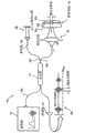
图1示出了示例性的现有技术的时域光学相干层析成像法(“OCT”)系统10,其包括将信号提供给二对二分光器14的第一臂14a的宽带源12。分光器分割在端口14a提供给它的信号,并且在耦合到参考臂16的端口14b提供该信号的第一部分。分光器14还在耦合到样品臂18的端口14c提供该信号的第二部分。FIG. 1 illustrates an exemplary prior art time-domain optical coherence tomography (“OCT”)
样品臂18终结于样品体积19,并且用于提供样品体积的侧向扫描的装置22被设置在样品体积19之前的样品臂18中。参考臂16终结于用于提供轴向扫描的装置20中。装置20和22的操作在本领域中众所周知。The
从装置20和样品体积19分别沿着参考和样品臂16、18反射回的信号耦合回到分光器14的相应端口14b、14c,并耦合到产生轴向扫描数据26的检测器24,这是众所周知的。其全部公开通过引用结合于此的美国专利6,341,036描述了与以上所述并在图1中示出的系统相似的系统。Signals reflected back from the
一般而言,在扫描参考臂路径长度16时,形成了干涉条纹,其对应于与到样品体积19中的三个结构19a、19b、19c的距离匹配的位置。单个检测器24用来检测干涉条纹。通过条纹图案的包络检测,构造了图像26,其将组织反射率映射到给定位置。In general, when scanning the reference arm path length 16 , interference fringes are formed which correspond to positions matching the distances to the three
如将根据在此下面所描述的某些示例性实施例而显而易见的,本发明的一个示例性的实施例涉及一种系统,其利用了基于光谱雷达概念(又称为谱域OCT)的检测原理和/或谱域和时域OCT之间的混合方法,该方法优选地比当前现有时域OCT灵敏,从而允许采集速度与分辨率的比的基本增加。As will be apparent from certain exemplary embodiments described herein below, an exemplary embodiment of the invention relates to a system utilizing detection based on the concept of spectral radar (also known as spectral domain OCT) A principle and/or hybrid approach between spectral domain and time domain OCT, which is preferably more sensitive than currently available time domain OCT, allowing a substantial increase in the ratio of acquisition speed to resolution.
先前已在相关出版物中描述了时域OCT中的信噪比(“SNR”)的分析。时域OCT中的干涉条纹峰值振幅由下面给出:Analysis of signal-to-noise ratio ("SNR") in time-domain OCT has been described previously in related publications. The peak amplitude of the interference fringes in time-domain OCT is given by:
其中Pref、Psample分别是以瓦表示的参考和样品臂功率。就检测器处的电功率而言,以单位[A2]表示的信号定义为:WherePref andPsample are reference and sample arm power expressed in watts, respectively. In terms of electrical power at the detector, the signal in units [A2 ] is defined as:
其中η是量子效率,e是电荷量子,Ev=hc/λ是光子能量。参考和样品臂功率由相应的反射光谱密度给出:where η is the quantum efficiency, e is the charge quantum, and Ev =hc/λ is the photon energy. The reference and sample arm powers are given by the corresponding reflectance spectral densities:
Pref,sample=∫Sref,sample(ω)dω. (3)Pref, sample = ∫Sref, sample (ω)dω. (3)
假定参考和样品谱密度等于源谱密度S(ω),其中样品臂谱密度被衰减大的倍数,即Sref(ω)=S(ω)、Ssample(ω)=αS(ω),其中α<<1,并且将参考和样品臂的上述表达式插入信号的原始定义,得到:Assume that the reference and sample spectral densities are equal to the source spectral density S(ω), where the sample arm spectral density is attenuated by a large multiple, that is, Sref (ω)=S(ω), Ssample (ω)=αS(ω), where α << 1, and plugging the above expressions for the reference and sample arms into the original definition of signal yields:
对OCT信号的总噪声的三个贡献是:(i)热噪声,(ii)散粒噪声和(iii)相对强度噪声。热噪声由反馈电阻生成,散粒噪声与导致电流的统计波动的电荷量子的有限性质相关,并且相对强度噪声与由于经典光源的混沌特性的时间波动相关。以单位[A2/Hz]表示的这三个对噪声强度的贡献由下面给出:Three contributions to the total noise of the OCT signal are: (i) thermal noise, (ii) shot noise and (iii) relative intensity noise. Thermal noise is generated by the feedback resistor, shot noise is related to the finite nature of the charge quanta causing statistical fluctuations in the current, and relative intensity noise is related to temporal fluctuations due to the chaotic nature of classical light sources. These three contributions to the noise intensity expressed in units [A2 /Hz] are given by:
k是玻尔兹曼常数,T是以开尔文表示的温度,Rfb是反馈电阻的值,τcoh是源的相干时间。相干时间通过下面的关系:
信噪比(SNR)由下面给出:The signal-to-noise ratio (SNR) is given by:
其中BW是信号带宽,参数S和Nnoise(f)如上所述。where BW is the signal bandwidth and the parameters S and Nnoise (f) are as described above.
使用光谱仪和CCD阵列检测器的谱域OCTSpectral Domain OCT Using Spectrometers and CCD Array Detectors
当噪声是散粒噪声受限时,获得了时域OCT系统的最佳信噪比性能。散粒噪声可通过将单元件检测器替换为多元件阵列检测器来显著地减小。当在阵列检测器上谱色散检测臂光时,阵列的每个元件检测源的谱宽的小波长部分。散粒噪声优选地减小一个倍数,该倍数等于阵列元件数。信噪比改善的原理基于散粒噪声的白噪声特性以及仅相同波长的电磁波产生干涉条纹的观测。The best SNR performance of time-domain OCT systems is obtained when the noise is shot-noise limited. Shot noise can be significantly reduced by replacing the single element detector with a multi-element array detector. Each element of the array detects a small wavelength portion of the spectral width of the source when the dispersive detection arm light is spectrum across the array detector. Shot noise is preferably reduced by a factor equal to the number of array elements. The principle of SNR improvement is based on the white noise characteristics of shot noise and the observation that only electromagnetic waves of the same wavelength produce interference fringes.
散粒噪声功率密度Nnoise(f)(以单位[W/Hz]、[A2/Hz]或[V2/Hz]表示)与在检测器中生成的电流(或等价地,光功率乘以量子效率)成比例。对于进入干涉计的波长λI的单色束,检测器处的条纹频率或载波f由镜的速度v确定,f1=2v/λ1。散粒噪声与波长λI处的功率(或谱密度S(ω))成比例。第二波长λ2优选地耦合到干涉计中。第二条纹频率或频率f2=2v/λ2处的载波同时存在。此第二频率处的散粒噪声优选地是由波长λl和λ2处的光功率生成的散粒噪声之和。而且,在频率fl处,散粒噪声是由波长λl和λ2处的光功率生成的散粒噪声之和。因此,在两个频率处,交叉散粒噪声(cross-shot noise)项由检测器处两个波长的同时存在而生成。通过将每个波长谱色散到一个单独的检测器,可以消除交叉散粒噪声项。以此方式,谱域OCT提供了优于时域OCT系统的信噪比的显著改善。Shot noise power density Nnoise (f) (expressed in units [W/Hz], [A2 /Hz] or [V2 /Hz]) versus the current generated in the detector (or equivalently, the optical power multiplied by the quantum efficiency) to scale. For a monochromatic beam of wavelengthλΙ entering the interferometer, the fringe frequency or carrier f at the detector is determined by the mirror velocity v, f1 =2v/λ1 . Shot noise is proportional to the power (or spectral density S(ω)) at wavelengthλI . The second wavelengthλ2 is preferably coupled into the interferometer. A second fringe frequency or a carrier at frequency f2 =2v/λ2 exists simultaneously. The shot noise at this second frequency is preferably the sum of the shot noise generated by the optical power at wavelengthsλ1 andλ2 . Also, at frequencyfl , the shot noise is the sum of the shot noise generated by the optical power at wavelengthsλ1 andλ2 . Thus, at two frequencies, a cross-shot noise term is generated by the simultaneous presence of the two wavelengths at the detector. Cross shot noise terms are eliminated by spectrally dispersing each wavelength to a separate detector. In this way, spectral domain OCT provides a significant improvement in signal-to-noise ratio over time domain OCT systems.
OCT信号在空间域中最容易描述。对于样品臂中的单个目标,OCT信号的干涉项与源光谱S(ω)的傅立叶变换的实部成比例:OCT signals are most easily described in the spatial domain. For a single target in the sample arm, the interference term of the OCT signal is proportional to the real part of the Fourier transform of the source spectrum S(ω):
I(Δz)ocRe∫exp(ikΔz)S(k)dk (7)I(Δz)ocRe∫exp(ikΔz)S(k)dk (7)
其中Δz是样品和参考臂之间的路径长度差,k是波矢。作为时间的函数,OCT信号由下面给出:where Δz is the path length difference between the sample and reference arms and k is the wave vector. As a function of time, the OCT signal is given by:
I(t)ocRe∫exp(2iωrv/c)S(ω)dω (8)I(t)ocRe∫exp(2iωrv/c)S(ω)dω (8)
其中v是参考臂镜速度。该信号的频谱由时域中的信号的傅立叶变换给出,从而得到复函数。此函数的绝对值等于谱密度:where v is the reference arm mirror velocity. The frequency spectrum of this signal is given by the Fourier transform of the signal in the time domain, resulting in a complex function. The absolute value of this function is equal to the spectral density:
|I(f)|=|∫I(t)e2iπftdt|=S(πfc/v) (9)|I(f)|=|∫I(t)e2iπft dt|=S(πfc/v) (9)
其示出了信号带宽与源谱宽度成正比并且随着参考臂镜速度、即成像速度线性缩放。方程(9)还优选地将频谱的绝对值|I(f)|与信号S直接相关(见图4)。方程(9)还说明,光源的每个角频率或等价地该源的每个波长,以测得的干涉测量信号中的其自身的频率来表示。深度分布信息I(t)可以由傅立叶变换从复交叉谱密度|I(f)|获得。It shows that the signal bandwidth is proportional to the source spectral width and scales linearly with the reference arm mirror velocity, ie the imaging velocity. Equation (9) also preferably directly relates the absolute value of the spectrum |I(f)| to the signal S (see Figure 4). Equation (9) also states that each angular frequency of the source, or equivalently each wavelength of the source, is represented by its own frequency in the measured interferometric signal. The depth distribution information I(t) can be obtained from the complex cross spectral density |I(f)| by Fourier transform.
复交叉谱密度还可通过使用色散或干涉测量元件将信号I(t)分裂成若干谱带来获得。在每个检测器处,只确定复交叉谱密度的部分。将每个检测器的交叉谱密度组合,重新得到信号的全谱密度。因此,可通过将谱分量分离到各个检测器来获得相同的信息。以软件或硬件将所有检测器的信号组合将导致与利用单个检测器获得的信号相同的信号。The complex cross spectral density can also be obtained by splitting the signal I(t) into several spectral bands using dispersive or interferometric elements. At each detector, only a portion of the complex cross-spectral density is determined. The cross spectral densities of each detector are combined to retrieve the full spectral density of the signal. Therefore, the same information can be obtained by separating the spectral components to individual detectors. Combining the signals of all detectors in software or hardware will result in the same signal as obtained with a single detector.
在检测臂中,光谱可以分裂成二等分,其中两个检测器各检测光谱的一半。根据方程(9),检测器1和2处的频谱由下面分别给出:In the detection arm, the spectrum can be split into two halves, with two detectors each detecting half of the spectrum. According to equation (9), the spectra at
对于f<f0,|I1(f)|=S(πfc/v).,对于f>f0,I1(f)=0,并且For f<f0 , |I1 (f)|=S(πfc/v). For f>f0 , I1 (f)=0, and
对于f<f0,I2(f)=0,对于f>f0,|I2(f)|=S(πfc/v)。时域OCT中将由单个检测器采集的频谱由I1(f)和I2(f)之和I(f)=I1(f)+I2(f)给出。因此,在将光谱组合之后的信号S是相等的,然而对于f>f0,I1(f)=0,对于f<f0,I2(f)=0,每个检测器的带宽BW可以减小1/2。For f<f0 , I2 (f)=0, for f>f0 , |I2 (f)|=S(πfc/v). The spectrum to be acquired by a single detector in time-domain OCT is given by the sum of I1 (f) and I2 (f) I(f)=I1 (f)+I2 (f). Therefore, the signals S after combining the spectra are equal, however I1 (f)=0 for f>f0 and I2 (f)=0 for f<f0 , the bandwidth of each detector BW Can be reduced by 1/2.
噪声由检测器一和二处的散粒噪声贡献之和来确定。根据方程(5)和(6),每个检测器的散粒噪声与检测器处的参考臂功率和用于检测器的带宽之积成比例。由于光谱被分裂成二等分,所以检测器1和2处的参考功率分别是:Noise is determined by the sum of the shot noise contributions at detectors one and two. According to equations (5) and (6), the shot noise of each detector is proportional to the product of the reference arm power at the detector and the bandwidth used for the detector. Since the spectrum is split into halves, the reference powers at
对于两个检测器的散粒噪声贡献之和是:The sum of the shot noise contributions for the two detectors is:
其可以与时域OCT中的单个检测器的散粒噪声相比较:It can be compared to the shot noise of a single detector in time-domain OCT:
因此,通过在两个分离的检测器上谱色散检测和光,信号保持相同,但噪声减小1/2,导致2倍的净SNR增益。Thus, by spectrally dispersively detecting sum light on two separate detectors, the signal remains the same but the noise is reduced by 1/2, resulting in a net SNR gain of 2x.
扩展上面的分析,可证明散粒噪声贡献减小等于检测器数目的因子。N个检测器元件的散粒噪声之和由下面给出,其中每个检测器元件接收总的参考功率的N分之一:Extending the above analysis, it can be shown that the shot noise contribution is reduced by a factor equal to the number of detectors. The sum of the shot noise of N detector elements, where each detector element receives one-Nth of the total reference power, is given by:
信号与时域OCT中相同,且谱域OCT的SNR比由下面给出:The signal is the same as in time-domain OCT, and the SNR ratio of spectral-domain OCT is given by:
因此,依赖于检测器元件N的数目,谱域OCT实现了一百到一千倍的优于时域OCT的SNR的改善。将电荷耦合阵列或积分器件用作检测器,诸如但不限于线扫描相机,比率N/BCW由阵列的积分时间τi来替换,这导致:Thus, depending on the number of detector elements N, spectral-domain OCT achieves a one hundred to one thousand-fold improvement in SNR over time-domain OCT. Using a charge-coupled array or integrating device as a detector, such as but not limited to a line scan camera, the ratio N/BCW is replaced by the integration timeτ of the array, which results in:
图2示出了示例性的谱域OCT系统100,其包括干涉计102、包括多个检测器的检测器阵列114以及同样多个放大器116,其中干涉计102具有源臂104、样品臂106、参考臂108和具有光谱分离单元112的检测臂110。放大器116通过任选的模拟处理电子器件(未示出,但对于本领域的普通技术人员是公知的)和用于转换信号的A/D转换器(未示出,但对于本领域的技术人员是公知的)并且通过数字带通滤波(“BPF”)单元122耦合到处理和显示单元124。2 shows an exemplary spectral
处理和显示单元124执行数据处理和显示技术,并且可任选地包括数字带通滤波(“BPF”)单元122以及数字快速傅立叶变换(“DFFT”)回路(未示出),以便提供信号的相干组合以及执行数据处理和显示功能。检测器阵列114可以是:1×N,用于简单强度测距和成像和/或多普勒灵敏检测;2×N,用于双平衡检测;2×N,用于简单强度测距和/或偏振和/或多普勒灵敏检测,或4×N,用于组合的双平衡和偏振和/或多普勒灵敏检测。可替换地,可以针对任意数目“M”的检测器114使用M×N阵列以允许有关样品130的横向空间信息的检测。Processing and
电磁辐射(例如光)从源沿着源臂104传输到分裂单元通路(splittingunit via)并在参考臂108和样品臂106之间分裂。光沿着样品臂传播到组织样品130以及通过参考臂108传播到依赖于波长的相位装置。光从样品和依赖于波长的相位装置向着分裂单元反射回,在该分裂单元处,至少部分反射光导向谱分离单元112(其可例如提供为光栅)。检测臂光由谱分离单元112色散,并且谱被成像到检测器阵列114上。通过使参考臂108的长度跨过距离λ/8,可以确定参考臂108和参考臂106光的交叉谱密度。处理和显示单元接收馈送到它的信号并进行交叉谱密度的傅立叶变换以生成深度分布信息。Electromagnetic radiation (eg light) is transmitted from the source along
图3A示出了根据本发明的一个示例性的系统的块图,其图示了使用单频调谐源的相干频率调制连续波(“C-FMCW”)系统的基本原理。可操作为频率啁啾激光器的单色激光器光70将光信号提供给耦合器72的输入72a。耦合器72将光信号分割到终结于参考镜82的参考臂80和终结于样品86的样品臂84。光顺着路径80、84传播并从参考镜82和样品镜86反射以经由耦合器72提供由光电检测器88检测的干涉信号。3A shows a block diagram of an exemplary system illustrating the basic principles of a coherent frequency modulated continuous wave ("C-FMCW") system using a single-frequency tuned source in accordance with the present invention.
如图3B-3D的曲线图所示,当分别在两个反射光信号90(图3B)和92(图3C)之间存在光学延迟时,可以在光电检测器88处检测到具有频率f的拍频信号94(见图3D)。在沿轴在样品中有多个反射点的情况下,干涉由具有与样品和参考镜中的反射(散射)点之间的光学延迟差成比例的频率的拍音(beat note)组成。每个拍频分量的功率与散射的反射率成比例。由此,样品的图像可以通过干涉数据的傅立叶变换来构造。As shown in the graphs of FIGS. 3B-3D , when there is an optical delay between the two reflected light signals 90 ( FIG. 3B ) and 92 ( FIG. 3C ), respectively, a light with frequency f can be detected at
现在参考图4A-4D,其中提供了在上面描述并在图3A-3D中示出的具有相同参考标记的类似元件,根据本发明的一个示例性的实施例的光学频域成像(“OFDI”)系统包括波长扫描激光源95(在此也称为频率扫描源95),其将包括多个纵模的激光输出光谱提供给耦合器72的输入。耦合器72将馈送到它的信号分割到终结于参考镜82的参考臂80和终结于样品86的样品臂84。光信号从参考镜82和样品86反射以经由耦合器72提供由光电检测器88检测的信号的谱。Referring now to FIGS. 4A-4D , in which similar elements described above and shown in FIGS. 3A-3D are provided with the same reference numerals, optical frequency domain imaging ("OFDI" ) system includes a wavelength-swept laser source 95 (also referred to herein as frequency-swept source 95 ) that provides a laser output spectrum comprising a plurality of longitudinal modes to the input of
信号谱的中心(或中值)波长通过在该谱的前沿生成新的纵模和在该谱的后沿消除这些模在时间上加以调谐。The center (or median) wavelength of the signal spectrum is tuned in time by generating new longitudinal modes at the leading edge of the spectrum and canceling these modes at the trailing edge of the spectrum.
参考图3A-3D在上面描述的相同原理还可应用于使用波长扫描激光源95的OFDI技术。和C-FMCW系统(例如上面描述的图3A的系统)的情形相似,可以产生拍频信号94。在使用波长扫描激光源的OFDI系统的情形中,可以生成拍频信号94,其具有对应于分别来自参考和样品的光96和98的中心频率的差的拍频f。The same principles described above with reference to FIGS. 3A-3D can also be applied to OFDI techniques using a wavelength-swept
纵模之间的频率间距应该基本上大于检测带宽。在数字化之前,模式拍频(相对强度噪声峰)可由诸如低通滤波器的适当电子滤波器去除。干涉信号94包含与光学延迟成比例的频率分量。而且,样品的图像可以通过数字化的干涉数据的傅立叶变换来构造。The frequency spacing between longitudinal modes should be substantially larger than the detection bandwidth. Mode beat frequencies (relative intensity noise peaks) can be removed by suitable electronic filters such as low pass filters prior to digitization. The
在本发明的一个示例性的实施例中,可以提供波长扫描激光器95,其在激光腔内利用光学带通扫描滤波器来产生迅速扫描的多频率模式输出。结合图6和9A在下面描述根据本发明的示例性的滤波器。通过在激光腔内使用光学带通扫描滤波器,没有必要调谐激光腔长度来提供激光光谱的同步调谐。事实上,这样的装置不需要以与激光器的中心波长相同的速率来调谐激光器的纵腔模。In an exemplary embodiment of the present invention, a wavelength-swept
使用OFDI技术,图像的单个像素可以通过傅立叶变换从记录为一个A-扫描(A-scan)的持续时间内的时间的函数的信号来构造。这与TDOCT不同,在TD OCT中,单个像素从在一个A-扫描内的短时段测得的数据来构造。用来在相同的A-扫描时段内采集相同数目的数据的检测带宽对于TD和FD OCT二者大约是相同的。然而,与TD OCT相比,用于OFDI技术的傅立叶变换通过从在整个A-扫描时段内采集的很多数据构造单个像素而有效地改善了信噪比。此效应可导致“有效”检测带宽,该带宽是实际检测带宽的N倍。因此,可以将SNR提高到N倍,其中N是傅立叶变换中的(数字化的)数据点的数目。可示出散粒噪声受限情形中的SNR由下面给出:Using OFDI techniques, individual pixels of an image can be constructed by Fourier transforming a signal recorded as a function of time within the duration of an A-scan (A-scan). This differs from TDOCT, where individual pixels are constructed from data measured over a short period of time within one A-scan. The detection bandwidth to acquire the same amount of data in the same A-scan period is about the same for both TD and FD OCT. However, compared to TD OCT, the Fourier transform used in the OFDI technique effectively improves the signal-to-noise ratio by constructing a single pixel from many data acquired over the entire A-scan period. This effect can result in an "effective" detection bandwidth that is N times the actual detection bandwidth. Therefore, the SNR can be improved by a factor of N, where N is the number of (digitized) data points in the Fourier transform. It can be shown that the SNR in the shot noise limited case is given by:
然而,由于波长扫描源的窄带输出光谱,相对强度噪声(RIN)可显著地高于CW宽带光源的相对强度噪声。对于热光,RIN由1/Δv给出,其中Δv=c·Δλ/λ2是(瞬时)源输出的光学带宽。对于激光,RIN由不同的统计所引起并因此具有与热光不同的值。对于FD-OCT,具有低RIN水平的波长扫描激光器是优选的。具有多个纵模的激光可以具有与具有相同线宽的热光相似的RIN水平。在此情形中,抑制RIN的手段对于具有足够的SNR是关键的,如双平衡检测。However, due to the narrow-band output spectrum of the wavelength-swept source, the relative intensity noise (RIN) can be significantly higher than that of a CW broadband source. For thermo-optic, RIN is given by 1/Δv, where Δv = c·Δλ/λ2 is the optical bandwidth of the (instantaneous) source output. For lasers, the RIN is caused by different statistics and thus has different values than for thermo-optic. For FD-OCT, wavelength-swept lasers with low RIN levels are preferred. A laser with multiple longitudinal modes can have a similar RIN level to a thermal light with the same linewidth. In this case, a means of suppressing RIN is critical to have sufficient SNR, such as double-balanced detection.
扫描源的使用导致具有减小的散粒噪声和其它形式的噪声的系统,该系统允许比当前的系统低得多的源功率或高得多的采集速率。增加的检测灵敏度允许实时成像。这样的成像速度可有助于诸如胃肠、眼科和动脉γ成像环境中的运动假象的问题。通过增加帧速率同时维持或改善信噪比,可使这样的假象最小化。本发明还使得人们能够利用OFDI技术筛选大面积的组织,并且允许使用此方法的临床上的可行筛选协议。The use of a swept source results in a system with reduced shot noise and other forms of noise that allows for much lower source power or much higher acquisition rates than current systems. Increased detection sensitivity allows real-time imaging. Such imaging speed can help with problems such as motion artifacts in gastrointestinal, ophthalmic and arterial gamma imaging environments. Such artifacts can be minimized by increasing the frame rate while maintaining or improving the signal-to-noise ratio. The present invention also enables screening of large areas of tissue using OFDI techniques and allows for clinically viable screening protocols using this method.
对于OFDI的眼科应用,有效的检测优选地允许采集速度的显著增加。眼科应用的一个可能限制是根据ANSI标准(在830nm处大约700微瓦)允许进入眼睛的功率。眼科应用中的当前数据采集速度是每秒大约100-500个A-线。功率效率高的检测将允许每秒约100,000个A-线的量级的A-线采集速率,或以每个图像约3,000个A-线的视频速率成像。For ophthalmic applications of OFDI, efficient detection preferably allows a significant increase in acquisition speed. A possible limitation for ophthalmic applications is the power allowed into the eye according to ANSI standards (approximately 700 microwatts at 830nm). Current data acquisition rates in ophthalmic applications are approximately 100-500 A-lines per second. Power efficient detection would allow A-line acquisition rates on the order of about 100,000 A-lines per second, or imaging at a video rate of about 3,000 A-lines per image.
因为散粒噪声具有白噪声谱,所以实现了SNR的增益。频率ω(或波长λ)处的存在于检测器的信号强度只对频率ω处的信号有贡献,但是散粒噪声在所有频率处生成。通过使每个检测器的光学带宽变窄,可以减小每个频率处的散粒噪声贡献,同时信号成分保持相同。A gain in SNR is achieved because shot noise has a white noise spectrum. The signal strength present at the detector at frequency ω (or wavelength λ) only contributes to the signal at frequency ω, but shot noise is generated at all frequencies. By narrowing the optical bandwidth of each detector, the shot noise contribution at each frequency can be reduced while the signal content remains the same.
图5示出了用于使用频域干涉测量法(“OFDI”)进行光学成像的系统99的一个示例性的实施例,系统99包括频率扫描源100,其发射窄带谱,该窄带谱的中心波长在源中的增益介质(gain medium)的带宽上、在时间上连续和重复调谐。瞬时发射谱由光源的多个频率模式组成。频率扫描源100可以以各种不同的方式提供,其中的一些在下面描述。例如,源100可提供自各种增益介质、可调谐波长滤波器、腔配置。器件和方法在本领域中是公知的,以提供迅速调谐的波长扫描激光源,诸如固态激光器、掺有活性离子的波导激光器和光纤激光器。还可使用模式锁定方案中的波长扫描激光器,其具有纵模拍频的谐波之间的频率区域中的较低相对强度噪声(RIN)的潜在优点。可在激光腔内或源的输出端口之后结合光学可饱和吸收器来降低RIN水平。FIG. 5 shows an exemplary embodiment of a system 99 for optical imaging using frequency-domain interferometry ("OFDI") that includes a frequency-swept
提供自扫描源100的光导向光纤耦合器102,光纤耦合器102将馈送到它的光分割到参考臂103和样品臂104中。在此示例性的实施例中,耦合器102具有90:10的功率分裂比,功率的90%导向样品臂。然而,本领域中的普通技术人员将理解还可以使用用于耦合器102的其它耦合比。在任何特定应用中使用的特定耦合比应选择为使得将一功率量提供给参考臂和样品臂二者以允许根据本发明的示例性系统的适当操作。Light provided from
提供给样品臂的功率通过环行器111并照亮将通过横向扫描成像探头来成像的样品136。参考臂优选地提供固定的光学延迟。从参考镜124和从样品136中反射的光可通过相应的环行器110、111导向光纤分束器(或熔接耦合器(fused coupler))150并在彼此之间干涉以产生干涉信号。Power supplied to the sample arm passes through the
理想的是,组合耦合器150在源的波长调谐范围上具有相等的分裂比,其具有最小的偏振依赖性和波长依赖性。与相等分裂的偏离导致双平衡检测的共模抑制比(“CMRR”)的减小。在一个实施例中,组合耦合器150优选地提供为体宽带分束器(bulk broadband beam splitter)。本领域的普通技术人员将理解还可以使用其它类型的耦合器(包括但不限于波长平坦化光纤熔接耦合器)。Ideally, the combined
干涉信号由双平衡接收器151接收。接收器151的输出被提供到计算装置(例如数据采集板和计算机160),使得输出由计算机装置数字化并处理以产生图像。数据采集、横向扫描和波长调谐被同步控制。The interference signal is received by a double-
图6示出了可以例如适于用作频率扫描源(诸如参考图5在上面描述的频率扫描源100)的示例性的光源100′,其提供自光学滤波器170,通过透镜172和光路174耦合到光源/控制器176(下文称为“光控制器176”)。光控制器176又可以耦合到一个或多个应用178。应用178可以例如对应于光学成像过程和/或光学成像系统、激光加工过程和系统、光刻法和光刻系统、激光地形系统、电信过程和系统。由此,提供自滤波器170和光控制器176的示例性的光源100′可以在多种不同应用中使用,在此描述其某些一般的实例。FIG. 6 shows an exemplary
如将在下面更详细地描述的,滤波器170允许光源100′操作为发射如此光谱的频率扫描源,该光谱的中心波长可在光控制器176的带宽上、在时间上连续和重复调谐。由此,光源100′可以具有包括光源/控制器176的多个频率模式的瞬时发射光谱。在此示例性的实施例中,光学波长滤波器170配置为反射型滤波器,其中输入和输出端口是相同的。由此,光路174可以例如提供为输入/输出光纤,并且透镜172可以对应于准直透镜。虽然示出图6中的滤波器170通过光控制器176耦合到一个或所有应用178,但是有可能将滤波器170直接耦合到一个或多个应用178。可替换地,有可能通过与光控制器不同的器件将滤波器170耦合到一个或多个应用178。As will be described in more detail below,
在根据本发明的该示例性的实施例中,光控制器176可包括许多专门适于传输具有宽频率(f)谱的光束(在一个实施例中,准直光束)的系统。具体而言,光束可包括可见光光谱(例如红、蓝、绿)内的多个波长。由光控制器提供的光束还可以包括限定在可见光光谱之外的多个波长(例如红外)。In this exemplary embodiment according to the invention,
如将参考图7在下面更详细地描述的,在本发明的一个示例性的实施例中,光控制器176可包括单向光传输环。在将在下面结合图9详细描述的另一示例性的实施例中,光控制器176可包括线性谐振器系统。滤波器170包括波长色散元件180,其适于从光控制器176接收光束以及将光束分离成多个不同波长的光,每个沿着一个光路导引,如所公知的。波长色散元件180可包括一个或多个元件,它们适于从光控制器176接收光束以及将光束分离成多个不同波长的光,每个沿着一个光路导引。波长色散元件180进一步操作成将多个波长的光以相对于光轴182的多个角方向或位移来导引。在本发明的一个示例性的实施例中,波长色散元件180可包括光色散元件,如反射光栅184。波长色散元件180可以可替换地提供为透射光栅(例如,诸如Dickson型全息光栅的透射型光栅)、棱镜、衍射光栅、声光衍射单元或一个或多个这些元件的组合。As will be described in more detail below with reference to FIG. 7 , in an exemplary embodiment of the invention,
波长色散元件180将每个波长的光沿着与光轴182成一角度的路径导向透镜系统186。每个角度由波长色散元件180来确定。透镜系统186可包括一个或多个光学元件,其适于从波长色散元件180接收分离波长的光以及将这些波长的光导引或指引和/或聚焦到位于束偏转器件188上的预定位置。可以控制束偏转器件188来接收一个或多个离散波长的光并选择性地将其沿着光轴182、通过透镜系统186重新导引会到波长色散元件180并回到光控制器176。此后,光控制器176可将接收的离散波长的光选择性地导向应用178的任何一个或多个。束偏转器件188可以以许多方式形成和/或设置。例如,束偏转器件188可提供自如此元件,其包括但不限于多面镜、设置在旋转轴上的平面镜、设置在检流计上的镜或声光调制器。The
在图6中示出的示例性的实施例中,色散元件186包括衍射光栅184、透镜系统186(其具有用来形成望远镜193的第一和第二透镜190、192)和以多面镜扫描器194示出的束偏转器件188。望远镜193提供自具有4-f配置的第一和第二透镜190、192。望远镜193的第一和第二透镜190、192每个基本上以光轴182为中心。第一透镜190位于距波长色散元件180(例如衍射光栅184)的第一距离处,该距离大约等于第一透镜190的焦距F1。第二透镜192位于距第一透镜190的第二距离处,该距离大约等于第一透镜190的焦距F1与第二透镜192的焦距F2之和。在此示例性的设置中,第一透镜190可从波长色散元件180接收准直的离散波长的光,并且可以对准直的一个或多个离散波长的光中的每一个有效地进行傅立叶变换以提供投射到图像平面(见图6的标示的IP)的相等的一个或多个会聚束。图像平面IP位于第一和第二透镜之间并且位于距第一透镜的预定距离处,该预定距离由第一透镜的焦距F1来限定。在传播通过图像平面IP之后,会聚束(多个会聚束)形成由第二透镜接收的相等的一个或多个发散束。第二透镜操作成接收这一个或多个发散束以及提供具有相对于光轴182的预定角位移的相等数目的准直束,以便将准直束导引或指引到束偏转器件188的预定部分。In the exemplary embodiment shown in FIG. 6, the
望远镜193配置成提供如上所述的许多特征,并且进一步配置成将来自光栅的发散角色散转换为第二透镜192之后的会聚角色散,这是滤波器170的适当操作所需要的。另外,望远镜193提供了有用的自由度,其控制调谐范围并减小了多面镜194处的束尺寸以避免削束(beamclipping)。
如图6中所示,多面镜194优选地根据相对于光轴的多面体的前镜面的角度仅反射回窄通带内的谱分量。所反射的窄带光由光纤174衍射和接收。As shown in FIG. 6,
入射束相对于光轴的取向和多面镜194的旋转方向198确定波长调谐的方向:波长上(正)扫描或下(负)扫描。图6中的装置产生正的波长扫描。应当理解,尽管在图6中镜194示出为具有十二个面,也可以使用少于或多于十二个面。用于任何应用的特定数目的面依赖于特定应用的所需扫描速率和扫描范围。而且,镜的尺寸根据特定应用的需要来选择,这些需要考虑了包括但不限于镜194的可制造性和重量的因素。还应当理解,可提供具有不同焦距的透镜190、192。透镜190、192应选择为提供大约在镜194的中心点200处的焦点。The orientation of the incident beam relative to the optical axis and the
考虑从光纤准直器172入射到光栅的具有宽光谱的高斯束。众所周知的光栅方程表达为:λ=p·(sinα+sinβ),其中λ是光波长,p是光栅节距,α和β分别是该束相对于光栅的标称轴202的入射和衍射角。滤波器的调谐范围的中心波长由λ0=p·(sinα+sinβ0)给出,其中λ0是望远镜的光轴38和光栅法向轴之间的角度。可示出滤波器的FWHM带宽由(δλ)FWHM/λ0=A·(p/m)cosα/W给出,其中对于双通,m是衍射级,W是光纤准直器处的高斯束的1/e2-宽度。当确定了复光谱密度的实部时,测距深度z由
滤波器的调谐范围基本上由透镜120的有限数值孔径限制。无削束的透镜1的接受角由Δβ=(D1-Wcosβ0/cosα)/F1给出,其中D1和F1是透镜1的直径和焦距。其经由Δλ=pcosβ0·Δβ与滤波器调谐范围相关。源自多面镜的多面性质的滤波器的一个重要设计参数是自由谱范围,其将在下面描述。传播通过透镜120和透镜222之后的谱分量将具有以相对于光轴38的角度β′的束传播轴:β′=-(β-β0)·(F1/F2),其中F1和F2分别是透镜1和透镜2的焦距。多面体具有由θ=2π/N≈L/R给出的面对面的极角,其中L是面宽度,R是多面体的半径,N是面的数目。如果入射光谱的β′的范围大于面角,即Δβ′=Δβ·(F1/F2)>θ,则多面镜可在给定时间向后反射多于一个谱分量。同时被反射的多个谱分量的间距,或自由谱范围可示出为(Δλ)FSR=pcosβ0(F2/F1)·θ。The tuning range of the filter is substantially limited by the finite numerical aperture of the
在作为腔内扫描滤波器的应用中,如果增益介质具有均匀展宽,则激光器的调谐范围不能超过自由谱范围,因为激光器选择最高增益的波长。如果满足以下两个必要条件,则通过滤波器的激光调谐的占空比在原则上可以是100%而没有由削束引起的过多损耗:In applications as intracavity scanning filters, if the gain medium has uniform broadening, the tuning range of the laser cannot exceed the free spectral range because the laser selects the wavelength of highest gain. The duty cycle of laser tuning through the filter can in principle be 100% without excessive losses caused by beam clipping if the following two necessary conditions are met:
第一个方程根据透镜192之后的束宽度应小于面宽度的条件得到。第二个方程根据的是分别在调谐范围的最低和最高波长204、206处的两个束不应在多面镜处彼此重叠,方程(1)中的S指示透镜192和多面体的前镜之间的距离。The first equation follows from the condition that the beam width after lens 192 should be smaller than the facet width. The second equation is based on the fact that the two beams at the lowest and
在一个实验中,选择了具有下列参数的光学部件:In one experiment, optics were selected with the following parameters:
W=1.9mm,p=1/1200mm,α=1.2rad,β0=0.71rad,m=1,W=1.9mm, p=1/1200mm, α=1.2rad, β0 =0.71rad, m=1,
D1=D2=25mm,F1=100mm,F2=45mm,N=24,R=25mm,L=6.54,S=5mm,D1 =D2 =25mm, F1 =100mm, F2 =45mm, N=24, R=25mm, L=6.54, S=5mm,
θ=0.26rad,λ0=1320nm。根据这些参数,可以计算理论FWHM带宽、调谐范围和自由谱范围:(δλ)FWHM=0.09nm,Δλ=126nm and(Δλ)FSR=74nm。(1)中的两个条件都有裕度地得到满足。滤波器的特性使用来自半导体光放大器(SOA)和光谱分析器的宽带放大器自发发射光来测量。光谱分析器以峰保持模式记录归一化(nonnalized)通过量(反射)谱,同时多面镜以其15.7kHz的最大速度旋转。测得的调谐范围是90nm,这充分小于126nm的理论值。此差异归因于望远镜的象差,主要是与来自光栅的束的相对大的角发散相关联的场曲。预期将通过使用最优化的透镜来改善象差。自由谱范围是与理论计算一致的73.5nm。FWHM带宽测量为0.12nm。考虑光学元件的象差和缺陷,与0.11nm的理论极限的差异可能是合理的。θ=0.26rad, λ0 =1320nm. From these parameters, the theoretical FWHM bandwidth, tuning range and free spectral range can be calculated: (δλ)FWHM = 0.09 nm, Δλ = 126 nm and (Δλ)FSR = 74 nm. Both conditions in (1) are satisfied with a margin. The characteristics of the filters are measured using broadband amplifier spontaneous emission light from semiconductor optical amplifiers (SOAs) and spectral analyzers. The spectrum analyzer records the normalized (nonnalized) throughput (reflection) spectrum in peak-hold mode while the polygon mirror rotates at its maximum speed of 15.7 kHz. The measured tuning range is 90 nm, which is well below the theoretical value of 126 nm. This difference is due to aberrations of the telescope, primarily field curvature associated with the relatively large angular divergence of the beam from the grating. It is expected that aberrations will be improved by using optimized lenses. The free spectral range is 73.5nm which is consistent with theoretical calculations. The FWHM bandwidth was measured to be 0.12nm. The difference from the theoretical limit of 0.11nm may be reasonable considering the aberrations and imperfections of the optical components.
图7示出了根据本发明的一个示例性的实施例的扩展腔半导体激光器208,其可包括滤波器210,滤波器210可以例如相似于参考图6在上面描述的滤波器170。滤波器210通过光导引元件212和光路214耦合到法拉第环行器216。在此示例性的实施例中,滤波器210包括光栅232和多面镜236。由此,滤波器210可以对应于基于多面体的滤波器。马达234驱动该镜。FIG. 7 shows an extended
此示例性的实施例的法拉第环行器216通过偏振控制器220、222耦合到增益介质224,增益介质224在一个示例性的实施例中可以是半导体光学放大器(例如SOA,Philips,CQF 882/e),其耦合到电流源226,电流源226将注入电流提供给SOA224。腔内元件可以由例如单模光纤连接。两个偏振控制器220、222可对准腔内光的偏振态以对准到光栅232的最大效率的轴和SOA224的最大增益的轴。The Faraday circulator 216 of this exemplary embodiment is coupled through
激光输出228可通过光纤熔接耦合器230的90%端口来获得。为了生成对潜在应用有用的同步信号,激光输出的5%可通过具有0.12nm的带宽的可变波长滤波器237来耦合并且被导向光电检测器238。在一个示例性的实施例中,滤波器的中心波长可以固定在1290nm。当激光器的输出波长被扫描过固定波长滤波器的窄带通带时,检测器信号生成短脉冲。同步脉冲的时序通过改变滤波器的中心波长来控制。
图8A示出了当多面镜(即图7中的镜236)以15.7kHz的速率旋转时,如通过光谱分析器以峰保持模式所测得的参考图7在上面描述的类型的激光器的输出光谱的曲线图240。在等于滤波器自由谱范围的73nm-宽度上,沿到沿的扫描范围可以从1282nm到1355nm。测得的光谱的类高斯分布,而不是方形分布,可能是由于由滤波器的偏振敏感性以及腔内的双折射引起的依赖于偏振的腔损耗。优选地调节偏振控制器以获得最大扫描范围和输出功率。Figure 8A shows the output of a laser of the type described above with reference to Figure 7 as measured by a spectrum analyzer in peak-hold mode when the polygon mirror (i.e.,
图8B示出了时域中的激光输出的曲线242。上迹线244对应于通过固定波长滤波器获得的同步信号。从面到面的功率变化的幅度小于3.5%。峰值和平均输出功率分别是9mW和6mW。应当提及,曲线240的y轴刻度必须根据时域测量来校准,因为光谱分析器由于激光调谐速度比光谱分析器的扫描速度快得多而只记录时均谱。Figure 8B shows a
作为带内四波混合现象的结果,随着光通过SOA增益介质(例如图7中的SOA224),腔内激光的光谱的频率下移可上升。在频率下移存在时,正波长扫描可便于激光光谱的调谐,并由此产生较高的输出功率。激光输出的峰值功率可以根据调谐速度来测量。负的调谐速度可通过翻转准直器的位置和光栅相对于光轴(例如图6中的轴182)的取向来获得。优选地使滤波器的物理参数在两个调谐方向上近似相同。由此,自频移和正调谐的组合动作允许获得较高的输出并且使得激光器以较高的调谐速度操作。因此,正波长扫描可以是优选的操作。输出功率可以随着增加的调谐速度减小。由此,对于减小功率输出对调谐速度的敏感度,短的腔长度可能是理想的。在此情形中,自由空间激光腔是优选的。As a result of the phenomenon of in-band four-wave mixing, the frequency downshift of the spectrum of intracavity lasing can rise as light passes through the SOA gain medium (eg, SOA224 in Figure 7). Positive wavelength scanning facilitates tuning of the laser spectrum in the presence of frequency downshifts and thus yields higher output powers. The peak power of the laser output can be measured in terms of tuning speed. Negative tuning speeds can be obtained by flipping the position of the collimator and the orientation of the grating relative to the optical axis (eg,
图9A示出了根据本发明的一个示例性的实施例的自由空间扩展腔半导体可调谐激光器250的一个示例性的实施例,其包括在衬底芯片254上制造的半导体波导252,其通过准直透镜256耦合到多面体扫描滤波器255。前面258可以被抗反射地涂覆,并且输出面260被切割(cleaved)或优选地利用电介质涂覆以具有最佳的反射率。激光器的输出262通过输出耦合透镜264来获得。准直透镜256、264优选地以非球面透镜提供。FIG. 9A shows an exemplary embodiment of a free-space extended cavity
滤波器255包括波长色散元件180′,其适于接收从透镜256导向它的束。波长色散元件180′可以相似于参考图6在上面描述的波长色散元件180。透镜系统186′可布置在波长色散元件180′和束偏转器件188′之间。波长色散元件180′和束偏转器件188′可以相似于参考图6在上面描述的波长色散元件180和束偏转器件188。透镜系统186′包括一对透镜187a、187b,它们优选地提供为具有低象差的消色差透镜,尤其是场曲和彗差。
同步输出可通过使用透镜266、针孔268和位于向后反射自多面体扫描器272的光的0级衍射路径上的光电检测器270来获得。当特定波长的光束的焦点扫描过针孔268时,该检测器生成短脉冲。其它类型的增益介质可以包括但不限于掺入稀土离子的光纤、Ti:Al2O3和Cr4+:镁橄榄石。A synchronized output can be obtained by using
图9B示出了根据本发明的波长可调谐滤波器280的另一示例性的实施例,其可包括耦合到输入准直透镜282的光纤281,光学地耦合到衍射光栅284的聚焦透镜286,以及旋转盘288。衍射光栅284可以由诸如棱镜的其它角色散元件来替换。在一个示例性的实施例中,衍射光栅284可具有凹曲率,其焦距选择为使得无需聚焦透镜286。9B shows another exemplary embodiment of a wavelength
优选地,多于一个反射器290可沉积在旋转盘288的表面288a上。优选地,反射器290包括周期地和径向地图案化的多个窄条。用于反射器的材料优选地是金。盘288可由轻重量的塑料或硅衬底构成。代替沉积在盘的顶表面的反射器,盘可具有随后有附着到盘后表面的单个反射器的一系列通孔。从光纤281入射,不同波长的光束在由光栅衍射和由透镜286(在那些包括透镜286的系统中)聚焦之后可以在盘的表面上被照射成一个线。优选地,仅撞击旋转盘的反射器的束可以向后反射并由光纤281接收。镜292可以用来方便束达到盘上。Preferably, more than one
透镜286到盘288的反射器的距离等于透镜的焦距F。从光栅方程可以示出,滤波器的调谐范围由Δλ=pcosβ0(D/F)给出,其中D指示条之间的距离。条的宽度w优选地使得基本上等于盘表面处的束斑尺寸ws:
a.干涉计a.Interferometer
图10A示出了根据本发明的用于使用频域干涉测量法进行光学成像的OFDI系统300的一个示例性的实施例,其包括频率扫描源301,频率扫描源301发射具有包括光源的多个频率模式的瞬时发射谱的光信号。源301可以例如提供为参考图4A、5、6、7、9和9B在上面描述的源中的一个。来自源301的光可以被导向光纤耦合器302,其将馈送到其的光分割到参考臂303和样品臂304中。FIG. 10A shows an exemplary embodiment of an
参考臂303优选地包括偏振回路306和环行器308。由此,光从源301通过耦合器302、偏振回路306和环行器308传播到任选的运动假象回路309。任选的运动假象回路309可以提供自透镜310,其将光导向频移器311、相位跟踪器312和色散补偿器314。光通过任选回路309并入射到参考镜316上。应当理解,回路309起到去除和减少运动假象的作用。还应当理解,回路309可包括元件310-314的全部,和/或回路元件310-314中的一个或多个。The
样品臂304可包括环行器318。由此,发射自源301的光信号从源301通过耦合器302和环行器308传播到透镜320,透镜320将光导向扫描镜322。扫描镜322可提供自多种光学元件,包括但不限于检流计、压电激励器或另一功能上等效的器件。横向扫描器324耦合到扫描镜322和数据采集板和计算机326。数据采集板和计算机326还耦合到频率扫描源301。
图10A中示出的OFDI系统300还可包括偏振分集平衡检测(“PDBD”)回路334,其配置成从参考臂303和/或样品臂304接收信号。具体而言,参考臂303通过环行器308和偏振控制回路330连接到PDBD回路334的参考端口。相似地,样品臂304通过环行器318和偏振控制回路332连接到PDBD回路334的样品端口。The
b.干涉计b.Interferometer
样品臂304收集反射自组织样品328的光并且在偏振分集平衡检测(PDBD)回路334中与来自参考臂303的光组合以形成干涉条纹。
例如,OFDI技术不需要在时间上扫描参考臂中的光路长度。由此,在本发明的某些示例性的实施例中,可以优选地将参考臂提供为固定延迟参考臂。这样的固定延迟参考臂可以具有为本领域的普通技术人员所公知的各种配置。For example, the OFDI technique does not need to temporally scan the optical path length in the reference arm. Thus, in some exemplary embodiments of the invention, it may be preferred to provide the reference arm as a fixed delay reference arm. Such fixed delay reference arms may have various configurations known to those of ordinary skill in the art.
参考臂303可以是反射和/或透射型,并且可将光从镜316返回。返回的光经由环行器308导向偏振控制回路330。类似地,来自样品338的反射光可经由环行器318导向偏振控制回路332。参考臂也可以是透射而没有反射。偏振控制回路330可用来将参考臂光的偏振态与样品臂光的偏振态相匹配。应使干涉计中的总的双折射最小化以便不引起依赖于波长的双折射。偏振控制器可以包括但不限于基于弯曲引起的双折射或压缩(squeezing)的光纤偏振控制器。
优选地,在参考和样品臂之间,色度色散应基本上匹配。强色散失配的结果可能是轴向分辨率的损失。任何残余的色散都有可能由适当的信号处理来补偿,如基于傅立叶变换之前检测器数据的插值的非线性映射。此映射还可以至少部分地通过调节波长扫描源的光学布局来完成。在源301包括多面体扫描器和望远镜的一个实例中,可调节多面体扫描器和望远镜之间的距离以在傅立叶变换之前将波长空间转换成波矢空间。Preferably, the chromatic dispersion should be substantially matched between the reference and sample arms. A consequence of strong dispersion mismatch can be a loss of axial resolution. Any residual dispersion is likely to be compensated by appropriate signal processing, such as nonlinear mapping based on interpolation of the detector data prior to Fourier transform. This mapping can also be accomplished at least in part by adjusting the optical layout of the wavelength-sweeping source. In one example where
c.样品臂c.Sample arm
对于某些OFDI应用,样品臂可以终结于光学探头或自由空间束,该光学探头包括切割的(成角度的、平的或抛光的)光纤。透镜336(诸如但不限于非球面的、梯度折射率的、球面的、衍射的、球状的、鼓状的等等)可用来将束聚焦在样品上或样品内。在探头中还可包含束导引元件(诸如但不限于镜、棱镜、衍射光学元件等等)以将聚焦的束导向样品上的所需位置。束的位置可以根据时间在样品上变化,从而允许二维图像的重构。改变聚焦的束在样品上的位置可以通过扫描镜322来完成。扫描镜322可以提供自例如许多不同的器件,包括但不限于检流计、压电激励器、电光激励器等等。For some OFDI applications, the sample arm can terminate in an optical probe comprising cleaved (angled, flat or polished) optical fiber or a free-space beam. A lens 336 (such as, but not limited to, aspheric, gradient index, spherical, diffractive, spherical, drum, etc.) may be used to focus the beam on or within the sample. Beam directing elements such as, but not limited to, mirrors, prisms, diffractive optical elements, etc., may also be included in the probe head to direct the focused beam to a desired location on the sample. The position of the beam can vary over the sample as a function of time, allowing the reconstruction of two-dimensional images. Changing the position of the focused beam on the sample can be accomplished by scanning
样品臂探头可以是具有内部运动元件的光纤探头,使得该运动在探头的近端启动,并且该运动通过运动转换装置(诸如但不限于线、引导线、速度计线缆、弹簧、光纤等等)传送到远端。光纤探头可以被封入光学透明的静止护套,其中光在远端退出探头。由此,扫描方式也可通过移动光纤来完成。例如,通过旋转光纤,或线性地平移光纤。图10B示出了探头359的一个示例性的实施例,其包括内线缆360(其可沿着探头的轴旋转或线性平移)、透明或半透明外护套362、远端光学器件364和转移的光(remitted light)366(其可以处于相对于导管的轴的任何角度)。The sample arm probe may be a fiber optic probe with internal motion elements such that the motion is initiated at the proximal end of the probe and the motion is passed through a motion translation device such as but not limited to wire, guide wire, velocimeter cable, spring, fiber optic, etc. ) to the remote end. The fiber optic probe can be enclosed in an optically transparent stationary sheath where light exits the probe at the distal end. Thus, the scanning mode can also be accomplished by moving the optical fiber. For example, by rotating the fiber, or linearly translating the fiber. FIG. 10B shows an exemplary embodiment of a
d.检测d.Detection
PDBD回路334可以包括布置成提供双平衡检测的多个检测器370。在某些应用中,双平衡检测由于以下原因而可能是优选的。首先,大部分光源以相对低的频率生成1/f噪声(f=频率),并且平衡检测将消除1/f源噪声。其次,样品臂光与其自身的干涉项(即自相关项)可以出现在真信号项的顶部,其优选地是样品和参考臂之间的干涉。这样的自相关项可由差分技术来消除,并且平衡检测可以从测得的信号中消除此自相关项。第三,可减小RIN。The
检测器370可以优选地包括光电二极管(诸如但不限于硅、InGaAs、延展(extended)InGaAs等等)。平衡检测可通过减去相对于最大和最小图案完全不同相的二极管信号来实施。两个检测器信号之间的差通过包括在PDBD回路334中的差动回路来获得并且通过跨阻放大器(“TIA”)360来放大。双平衡接收器可以进一步由低通或带通滤波器跟随以抑制检测带宽之外的噪声。Detector 370 may preferably comprise a photodiode (such as, but not limited to, silicon, InGaAs, extended InGaAs, etc.). Balance detection can be implemented by subtracting diode signals that are completely out of phase with respect to the largest and smallest patterns. The difference between the two detector signals is obtained by a differential loop included in
在本发明的此示例性的实施例中,双平衡检测可按如下实施。偏振分束器362从参考和样品臂接收信号并提供两个输出信号。这两个输出信号分别由两个非偏振分束器364a、364b进一步分裂。来自每个分束器364a、364b的输出由提供自四个检测器370的双平衡接收器来检测。而且,双平衡接收器的两个输出在计算机装置中数字化和处理以获得偏振分集。In this exemplary embodiment of the invention, double-balanced detection may be implemented as follows.
接收器输出被提供给回路326,其采集馈送到其的信号并经由A/D转换器来数字化,并且在计算机中存储数字化的信号以便进一步的处理。TIA的带宽优选地与采样速率的一半匹配。TIA的增益优选地选择为使得最大接收器输出范围与A/D转换器的电压范围匹配。The receiver output is provided to
e.处理e.Processing
如果使用多于两个检测器,可选择性地减去信号并且可获得复谱密度。使用傅立叶变换,复交叉谱密度可转换为组织中的深度分布。用以处理复谱密度以获得深度分布信息的若干方法对于本领域的技术人员是公知的,这些方法诸如但不限于通过在参考臂中获得具有Pi/2相移的至少两个信号并然后通过这两个信号的某个线性组合重新连接复谱密度,或通过取谱密度的平方。If more than two detectors are used, the signal can optionally be subtracted and the complex spectral density can be obtained. Using a Fourier transform, the complex cross-spectral density can be converted to a depth profile in the tissue. Several methods to process the complex spectral density to obtain depth profile information are known to those skilled in the art, such as but not limited to by obtaining at least two signals with a Pi/2 phase shift in the reference arm and then by Some linear combination of these two signals reconnects the complex spectral density, or by taking the square of the spectral density.
跟随着检测,模拟处理可包括跨阻放大器、低通(带通)滤波器和信号的数字化。然后此信号可通过傅立叶变换运算转换成作为深度的函数的反射率。数字处理包括数字化、频域或时域(FIR或IIR滤波器)的数字带通滤波以及用以恢复作为深度的函数的组织反射率的逆傅立叶变换。Following detection, analog processing may include transimpedance amplifiers, low-pass (band-pass) filters, and digitization of the signal. This signal can then be converted to reflectivity as a function of depth by a Fourier transform operation. Digital processing includes digitization, digital bandpass filtering in frequency or time domain (FIR or IIR filter), and inverse Fourier transform to recover tissue reflectivity as a function of depth.
在傅立叶变换之前,所检测的非线性波长坐标优选地转换成规则采样的波矢空间。典型地,利用重新采样的对信号零填充、傅立叶变换和逆傅立叶变换可用于重新映射。本领域中公知的其它插值方法,诸如数据的线性的、双线性的和三次样条插值也可用来将波长空间转换成规则采样的k空间。此映射也可部分地通过调节波长扫描源的光学布局来完成。在一个实例中,可调节多面体扫描器和望远镜之间的距离以在傅立叶变换之前将波长空间转换成波矢空间。The detected nonlinear wavelength coordinates are preferably transformed into a regularly sampled wave vector space prior to Fourier transformation. Typically, zero padding of the signal with resampling, Fourier transform and inverse Fourier transform can be used for remapping. Other interpolation methods known in the art, such as linear, bilinear and cubic spline interpolation of the data can also be used to convert the wavelength space into regularly sampled k-space. This mapping can also be accomplished in part by adjusting the optical layout of the wavelength-sweeping source. In one example, the distance between the polygon scanner and the telescope can be adjusted to convert wavelength space to wave vector space prior to Fourier transform.
本发明的另一示例性的实施例可利用在下面描述的一个或多个技术来进一步增强成像的性能和功能性。这些技术并不限于使用多频率模式调谐源的OFDI技术,而可应用于使用单频调谐源的OFDI技术。Another exemplary embodiment of the present invention may utilize one or more of the techniques described below to further enhance imaging performance and functionality. These techniques are not limited to OFDI techniques using multi-frequency mode tuning sources, but can be applied to OFDI techniques using single-frequency tuning sources.
a.偏振分集a.Polarization diversity
对于偏振衰落是问题的应用,可以使用偏振分集方案。用于偏振分集的各种配置在本领域中是公知的。For applications where polarization fading is an issue, polarization diversity schemes can be used. Various configurations for polarization diversity are known in the art.
在图10A中示出的系统中,偏振分集回路按如下操作。偏振分束器362依赖于参考臂的光信号和样品臂光信号的偏振态来分离它们。优选地调节偏振控制器330,使得参考臂功率由偏振控制器以相等的量值来分裂。可假设样品臂功率的偏振态可由于探头或样品运动而随机地变化,因此通过偏振分光器的样品臂功率的分离比可随时间变化。然而,偏振分束器362的两个输出端口处的两个输出信号可由光电接收器检测,例如取平方或求和。所得到的信号独立于样品臂光的偏振态。In the system shown in Figure 10A, the polarization diversity loop operates as follows. The
b.载频外差检测b.Carrier frequency heterodyne detection
光学频移器311可以处于参考臂303中以为载频外差检测而移位光学频率。结果,信号频带被移位该频移的量值。以此方式,可以避免DC周围的相对大的1/f噪声(f=频率)和RIN。频移器可以是但不限于声光频移器。在检测中,应使用合适的电子器件来解调载频。An
使用频移器311的优势之一是,可以使有效测距深度加倍。这可以以电频域说明,如图10C中所示,在该图中曲线图380描绘了由源的瞬时输出谱给出的条纹可见度曲线。如果源的瞬时谱是高斯型的,则该可见度曲线具有高斯分布。曲线390描绘了电滤波器的传输效率分布,其针对定义为采样频率的一半的给定的Nyquist频率而最优化。图10C的(a)部分示出了一个典型的情况,其中在干涉计中没有频移器并且电滤波器是低通滤波器。因为正的和负的频带不可区分,所以分别与正的和负的频带关联的图像是重叠的。在此情况中,由于此模糊(ambiguity),仅一半的频率范围(零到fN)或(零到-fN)可使用。然而,使用频移器导致可见度曲线被移位fFS,如图10C的(b)部分中所示出的。利用带通滤波器(或低通滤波器),以fFS为中心的频带的两侧产生没有模糊的图像,导致与图10C的(a)部分相比两倍大的测距深度。One of the advantages of using the
代替方顶带通滤波器,有可能使用斜率滤波器。在图10C的(c)部分中示出的实例中,滤波器390的传输效率曲线在其低频带具有指数上升(下降)的斜率。在衰减是显著的并且所得到的信号强度随深度衰退时,此滤波器可能是有用的。斜率滤波器可通过相对于较大深度处的信号有效地抑制来自表面的大信号来改善检测的动态范围。Instead of a square top bandpass filter it is possible to use a slope filter. In the example shown in part (c) of FIG. 10C , the transmission efficiency curve of
c.参考臂延迟(相位跟踪和自动测距)c. Reference arm delay (phase tracking and automatic ranging)
如上所述,OFDI技术不要求在时间上扫描参考臂中的光路长度。可以以本领域的普通技术人员所公知的各种配置来制作固定延迟的参考臂。参考臂可以是反射或透射型的。As mentioned above, the OFDI technique does not require temporal scanning of the optical path length in the reference arm. The fixed delay reference arm can be fabricated in various configurations known to those of ordinary skill in the art. The reference arm can be reflective or transmissive.
在某些应用中,当需要较大的测距深度,而不增加数据采集速率或减小光源的瞬时线宽时,改变参考臂中的光学延迟的能力可能是有用的。这样的能力在距成像透镜和样品的前表面的距离可显著变化的临床研究中是有用的。这样的变化可由运动或由探测导管的不受控制的位置所引起。例如,血管内的旋转导管可具有在单个A-扫描上几个毫米的距离变化。The ability to vary the optical delay in the reference arm may be useful in certain applications when greater ranging depths are required without increasing the data acquisition rate or reducing the instantaneous linewidth of the source. Such a capability is useful in clinical studies where the distance from the imaging lens and the anterior surface of the sample can vary significantly. Such changes may be caused by motion or by an uncontrolled position of the probe catheter. For example, a rotating catheter within a vessel may have a distance variation of several millimeters over a single A-scan.
参考臂303中的机构可以允许扫描参考臂303的群延迟。此群延迟可由为本领域的普通技术人员所公知的许多技术中的任何一种来产生,诸如但不限于延伸光纤、使用压电变换器的自由空间平移扫描或经由基于光栅的脉冲整形光学延迟线。优选地,延迟可以由非机械的或无运动的装置引入。术语“非机械的”的意思是未利用机械上移动的部件。认为机械上移动的部件的不存在减少了使用机械器件以引入延迟的公知的不足。与传统LCI或OCT系统对比,根据本发明的一个示例性的实施例的参考臂303不必在样品中的全部测距深度上扫描,并且可优选地至少在与一比检测器数目(1/N)相等的一个分数的测距深度上扫描。此扫描特征不同于在公知的LCI和OCT系统中使用的传统的延迟扫描方案。参考臂303任选地具有相位调制器机构,诸如但不限于声光调制器、电光相位调制器等等,以便生成载频。Mechanisms in the
优选地进行相位跟踪以消除干涉计中的相位不稳定。相位不稳定可引起各个干涉测量条纹在位置上移位。如果检测相对于条纹的移位是慢的,则所得到的平均导致干涉信号的啁啾。10到40kHz的A-扫描速率导致100到25μs的有效积分时间。应该补偿在比该积分时间短的时帧上的相位不稳定。相位锁定回路常用于电子器件,且频繁地用于雷达和超声。主动相位跟踪可通过在波长的一部分上利用参考臂中的电光相位调制器以10MHz调制干涉计路径长度差来实施。通过以路径长度调制的频率解调干涉计的输出处的一个检测器所测得的强度,可生成误差信号,其指示相位调制器应在哪个方向上移位以锁定到条纹幅度最大值上。通过如由误差信号所确定地将偏移添加到相位调制器,相位跟踪器主动地锁定到条纹最大值上。Phase tracking is preferably performed to eliminate phase instabilities in the interferometer. Phase instability can cause individual interferometric fringes to shift in position. If the shift of the detection relative to the fringe is slow, the resulting averaging leads to chirping of the interference signal. A-scan rates of 10 to 40 kHz result in effective integration times of 100 to 25 μs. Phase instabilities over time frames shorter than this integration time should be compensated for. Phase locked loops are commonly used in electronics and are frequently used in radar and ultrasound. Active phase tracking can be implemented by modulating the interferometer path length difference at 10 MHz with an electro-optic phase modulator in the reference arm over a fraction of the wavelength. By demodulating the intensity measured by one detector at the output of the interferometer with a path length modulated frequency, an error signal can be generated indicating in which direction the phase modulator should be shifted to lock onto the fringe amplitude maximum. The phase tracker actively locks onto the fringe maxima by adding an offset to the phase modulator as determined by the error signal.
相位调制器可在几个波长上调制路径长度差。处理单元可确定相位调制器是否已达到其范围极限,并且跳跃同相的全波以维持锁定在不同的条纹最大值上。此方法利用了相位应该仅以模2π来控制的事实。另外,所述处理驱动较慢的部件(例如迅速扫描光学延迟(“RSOD”)线)以将相位调制器/RSOD组合的路径长度范围扩展于若干毫米上。相位锁定可基于在调制回路中进行的混合类型对条纹最大值、最小值或零交叉进行。Phase modulators can modulate path length differences over several wavelengths. The processing unit can determine if the phase modulator has reached its range limit, and skip full waves in phase to maintain lock on a different fringe maxima. This method exploits the fact that the phase should only be controlled modulo 2π. In addition, the process drives slower components such as rapidly scanning optical delay ("RSOD") lines to extend the path length range of the phase modulator/RSOD combination over several millimeters. Phase locking can be done on fringe maxima, minima or zero crossings based on the type of mixing done in the modulation loop.
本发明的另一示例性的实施例还可使用自动测距技术和方法,包括在美国专利申请出版号2002/0198457中描述的处理技术,其公开整体地通过引用由此结合于此。在一个示例性的实施例中,自动测距机构可以包括处理器单元,用于:(a)获得第一扫描线;(b)定位样品的表面位置“S”;(c)定位样品的最优扫描范围“R”;(d)修改参考臂延迟波形以提供输出;(e)将该输出输出到参考臂;(f)确定图像是否完整;和/或(g)如果图像不完整则移动到下一扫描线或如果图像完整则使用存储在存储器存储器件中的表面S数据和波形数据来重新映射图像。Another exemplary embodiment of the present invention may also use automatic ranging techniques and methods, including the processing techniques described in US Patent Application Publication No. 2002/0198457, the disclosure of which is hereby incorporated by reference in its entirety. In an exemplary embodiment, the automatic ranging mechanism may include a processor unit for: (a) obtaining a first scan line; (b) locating the surface position "S" of the sample; (c) locating the maximum optimal scan range "R"; (d) modify the reference arm delay waveform to provide an output; (e) output that output to the reference arm; (f) determine if the image is complete; and/or (g) move if the image is incomplete The image is remapped to the next scanline or if the image is complete using the surface S data and waveform data stored in the memory storage device.
如果从样品返回的光信号具有低的振幅,则相位锁定由于噪声的存在而可能是不稳定的。在本发明的另一示例性的实施例中,单独的、优选地是单色的光源可发射到干涉计中。该单独源的波长可以在OFDI源的波长调谐范围内或可以以与OFDI源光谱不同的波长为中心。该单独源优选地具有较高的功率,并且可以与源臂组合(使用波分、复用器、光栅、棱镜、滤波器等等)行进到参考和样品臂并返回到束复合元件。然后,在通过束复合元件(即分束器输出)透射回之后,返回的单独源的光可与OFDI光分离。分离装置可通过色散元件进行谱分离,该色散元件诸如二向色镜、滤波器、光栅、棱镜、波分复用器等等。所述单独源将通过使用一个或多个检测器来与OFDI光分开检测。由该单独源提供的较高功率可使得能够检测较高幅度的干涉图案,并且向相位跟踪器提供改善的输入,由此使得能够进行较稳定的相位跟踪。If the optical signal returning from the sample has a low amplitude, the phase lock may be unstable due to the presence of noise. In another exemplary embodiment of the invention, a single, preferably monochromatic, light source may be emitted into the interferometer. The wavelength of the separate source may be within the wavelength tuning range of the OFDI source or may be centered on a different wavelength than the OFDI source spectrum. This separate source is preferably of higher power and can be combined with source arms (using wavelength division, multiplexers, gratings, prisms, filters, etc.) to travel to the reference and sample arms and back to the beam recombination element. Then, after being transmitted back through the beam recombining element (ie, the beam splitter output), the returning light of the individual source can be separated from the OFDI light. The separation means may perform spectral separation by dispersive elements such as dichroic mirrors, filters, gratings, prisms, wavelength division multiplexers, and the like. The separate source will be detected separately from the OFDI light by using one or more detectors. The higher power provided by this separate source may enable detection of higher magnitude interference patterns and provide improved input to the phase tracker, thereby enabling more stable phase tracking.
现在参考图11,使用根据本发明的系统和过程的示例性的实施例,示出了以15.7kHz的A-线扫描速率采集的受检者的指尖的活体内图像(300*500像素)。测得光学灵敏度为约-100dB。SNR优于相同A-线扫描速率的等效TD OCT。当存在来自组织表面的强的类似镜的反射时,垂直线噪声由于未最优化的检测而产生,但应优选地通过检测最优化和/或适当的信号处理来基本上消除。Referring now to FIG. 11 , an in vivo image (300*500 pixels) of a subject's fingertip acquired at an A-line scan rate of 15.7 kHz is shown using an exemplary embodiment of the system and process according to the present invention . The optical sensitivity was measured to be about -100 dB. SNR is better than equivalent TD OCT at the same A-line scan rate. Vertical line noise arises from sub-optimized detection when there are strong mirror-like reflections from the tissue surface, but should preferably be substantially eliminated by detection optimization and/or appropriate signal processing.
图12示出了根据本发明的相位跟踪器系统的另一示例性的实施例600,其提供了扩展的相位锁定范围。这通过将用以在小的范围内调制路径长度差的快速元件602(其可以例如以电光(EO)相位调制器602来提供)与用以在扩展的范围上调制路径长度的较慢元件604(其可以例如以迅速扫描光学延迟(RSOD)线604来提供)组合来实现。检测器606信号可以通过混合器610与相位调制器调制频率608混合并且被低通滤波(滤波器未示出)以生成误差信号。处理单元612优选地处理该误差信号以生成偏移电压,并将此偏移电压加到调制信号608,以便生成用于相位调制器驱动器614的输出。另外,处理单元612可生成到RSOD604的信号以在若干毫米的距离上提供相位的扩展范围跟踪。示出了光源616、光纤分光器618、样品臂620和参考臂622,并在此描述。FIG. 12 illustrates another
条纹图案的单个振荡内的给定时刻的检测器处的强度I(t)由下面给出:The intensity I(t) at the detector at a given instant within a single oscillation of the fringe pattern is given by:
I(t)=cos[φ(t)]I(t)=cos[φ(t)]
其中相位


φ(t)=α+βsin(ωt)φ(t)=α+βsin(ωt)
其中α描述了条纹图案的单个振荡内的位置,β*sin(ωt)是由相位调制器引入的相位调制,其中β是相位调制的振幅,ω是相位调制信号的频率。光电检测器处的强度I(t)可以与频率ω和2ω的载波混合,导致混合器信号MixerC(t)、MixerS(t)、Mixer2ωC(t)和Mixer2ωS(t):where α describes the position within a single oscillation of the fringe pattern and β*sin(ωt) is the phase modulation introduced by the phase modulator, where β is the amplitude of the phase modulation and ω is the frequency of the phase modulating signal. The intensity I(t) at the photodetector can be mixed with a carrier of frequency ω and 2ω resulting in the mixer signals MixerC(t), MixerS(t), Mixer2ωC(t) and Mixer2ωS(t):
MixerC(t)=cos(ωt)*cos(α+βsin(ωt));MixerC(t)=cos(ωt)*cos(α+βsin(ωt));
MixerS(t)=sin(ωt)*cos(α+βsin(ωt));MixerS(t)=sin(ωt)*cos(α+βsin(ωt));
Mixer2ωC(t)=cos(2ωt)*cos(α+βsin(ωt));Mixer2ωC(t)=cos(2ωt)*cos(α+βsin(ωt));
Mixer2ωS(t)=sin(2ωt)*cos(α+βsin(ωt)).Mixer2ωS(t)=sin(2ωt)*cos(α+βsin(ωt)).
在MixerC、MixerS、Mixer2ωC和Mixer2ωS的载频ω的单个振荡上的时间平均由下面给出:


图13示出了OFDI系统的又一示例性的实施例700,其包括用于根据本发明提供平衡检测的相位跟踪器。在此示例性的实施例中,源702提供通过分光器704的电磁辐射(例如光),分光器704将光的一部分发送到样品探头706并且将光的剩余部分发送到迅速扫描光学延迟(“RSOD”)线708。光从RSOD708传递到相位调制器PM710。来自相位调制器PM710的光传输通过分光器712,并然后通过两个附加的分光器714和716,其输出的一部分作为平衡检测输出发送到谱检测单元(未示出,但这里如别处所描述的),并且输出的剩余部分发送到相位跟踪器组件720。在相位跟踪器组件720中,相位跟踪器检测器D1和D2,722和724接收分光器对714和716的部分输出,其又将信号发送到混合器726以生成误差信号。处理单元728处理误差信号,在该处偏移电压的总和生成,并且将其加到调制信号730以产生用于相位调制器驱动器732的输出。在框730示出的调制信号被转发到混合器726和处理单元726。另外,条纹幅度可能太小使相位跟踪器难以锁定。可替换地,具有较长相干长度的二次源可耦合到例如系统700以将较大的条纹幅度提供到相位跟踪器。Figure 13 shows yet another exemplary embodiment 700 of an OFDI system including a phase tracker for providing balanced detection in accordance with the present invention. In this exemplary embodiment, source 702 provides electromagnetic radiation (e.g., light) through beamsplitter 704, which sends a portion of the light to sample probe 706 and the remainder of the light to a rapidly scanning optical delay ("RSOD") line 708. Light passes from RSOD 708 to phase modulator PM710. Light from phase modulator PM 710 is transmitted through beam splitter 712 and then through two additional beam splitters 714 and 716, a portion of whose output is sent as a balanced detection output to a spectral detection unit (not shown, but described elsewhere here). ), and the remainder of the output is sent to the phase tracker component 720. In phase tracker assembly 720, phase tracker detectorsD1 andD2 , 722 and 724 receive a portion of the output of splitter pair 714 and 716, which in turn sends the signal to mixer 726 to generate an error signal. Processing unit 728 processes the error signal, where the sum of the offset voltages is generated, and adds it to modulation signal 730 to produce an output for phase modulator driver 732 . The modulated signal shown at block 730 is forwarded to mixer 726 and processing unit 726 . Also, the fringe amplitude may be too small for the phase tracker to lock onto. Alternatively, a secondary source with a longer coherence length may be coupled to, for example, system 700 to provide larger fringe amplitudes to the phase tracker.
图14A-14C示出了成像系统中用于跟踪相位的方法的一个示例性实施例,根据本发明,其在处理块750和752开始于测量接收自样品臂的信号并然后增加信号的相位。然后此示例性的方法的处理前进到块754,在块754中,定义为x1的信号的第一信号分区被测量于至少一个信号峰。在决策块756中,确定定义为x1的信号是否已被测量于至少一个信号峰。如果在决策块756中,确定定义为x1的信号已被测量于至少一个信号峰,则处理返回到块754并且再次测量信号。Figures 14A-14C illustrate one exemplary embodiment of a method for tracking phase in an imaging system, which begins at processing blocks 750 and 752 by measuring the signal received from the sample arm and then adding the phase of the signal, in accordance with the present invention. Processing of the exemplary method then proceeds to block 754 where a first signal partition of the signal defined asx1 is measured at at least one signal peak. In
另一方面,如果在决策块756中,确定定义为x1的信号没有被测量于至少一个信号峰,则处理流向决策块758,在决策块758中,确定是否调节信号。调节可以例如是将信号相位增加或减小一渐进量(incremental amount),如块760和762中所示。不管是否作出信号相位的增加或减小,处理返回到处理块754,在块754中,信号的第二信号分区被测量于其峰处。然后对于这样的被测信号,重复块756-762。应当注意,块750-762的功能可以与其它成像过程并行地和/或串行地进行。On the other hand, if in
相位


d.数据处理d.Data processing
一般而言,在时间上由检测器记录的数据可不以光学频率ω或波数k的严格线性函数来采样。然而,傅立叶变换可链接z和k空间(或t和ω)。由于k中的非线性采样,采集的谱被插值以在k域中产生均匀间隔开的采样。可替换地,激光器的调谐斜率可以以这样的方式来调节,即光在k空间以相等的间隔采样,使得插值变得不需要。可替换地,检测时序可设计成对均匀扩展在k域中的光采样,使得插入变得不需要。为了实现最优的点扩散函数,应优选地平衡干涉计的样品和参考臂中的色散。色散不平衡也可由数字处理校正。由运动引起的相位啁啾也可由数字处理校正。对于运动假象校正,测量样品的轴向运动,并且可根据运动的速度计算适当的非线性映射。In general, data recorded by a detector in time may not be sampled as a strictly linear function of optical frequency ω or wavenumber k. However, the Fourier transform can link z and k spaces (or t and ω). Due to the non-linear sampling in k, the acquired spectra are interpolated to produce evenly spaced samples in the k domain. Alternatively, the tuning slope of the laser can be adjusted in such a way that the light is sampled at equal intervals in k-space such that interpolation becomes unnecessary. Alternatively, the detection timing can be designed to sample light spread uniformly in the k-domain, making interpolation unnecessary. To achieve an optimal point spread function, the dispersion in the sample and reference arms of the interferometer should preferably be balanced. Dispersion imbalance can also be corrected by digital processing. Phase chirp caused by motion can also be corrected by digital processing. For motion artifact correction, the axial motion of the sample is measured and an appropriate non-linear mapping can be calculated depending on the velocity of the motion.
对于本领域的普通技术人员,各种插值技术是公知的。这包括但不限于简单的两点插值、由两点插值跟随的FFT零填充,以及利用由Nyquist定理规定的sinc函数的严格插值。Various interpolation techniques are known to those of ordinary skill in the art. This includes, but is not limited to, simple two-point interpolation, FFT zero padding followed by two-point interpolation, and strict interpolation using the sinc function dictated by Nyquist's theorem.
本发明的一个示例性的实施例还可提供用于定位血管中的动脉粥样硬化斑块(atherosclerotic plaque)的探头,其包括:干涉计;将接收自干涉计的信号分裂成多个光学频率的谱分离单元;以及能够检测接收自谱分离单元的光学频率的至少一部分的检测器装置。An exemplary embodiment of the present invention may also provide a probe for locating atherosclerotic plaque in a blood vessel, comprising: an interferometer; splitting a signal received from the interferometer into a plurality of optical frequencies a spectral separation unit; and detector means capable of detecting at least a portion of the optical frequencies received from the spectral separation unit.
e.频移技术e.Frequency shift technology
对于高速OFDI技术,最大测距深度有可能受到激光输出的相干函数的有限宽度的限制,因为相干长度经常被折衷以获得较高的调谐速度、较高的输出功率或较宽的调谐范围。有限的相干长度可使干涉条纹的可见度随着干涉计的路径长度差的增加而减小。这导致SNR的降级,并因此限制了最大测距深度。而且,在传统的干涉测量法中,不能区分正的和负的电频率可导致正和负深度之间的模糊。为了避免成像折叠假象,应调节干涉计的参考延迟使得图像只存在于正或负深度。对于源的给定相干长度,这进一步可限制测距深度。For high-speed OFDI techniques, the maximum ranging depth is likely to be limited by the finite width of the coherence function of the laser output, since the coherence length is often traded off for higher tuning speed, higher output power, or wider tuning range. The finite coherence length causes the visibility of interference fringes to decrease as the interferometer path length difference increases. This results in a degradation of the SNR and thus limits the maximum ranging depth. Also, in conventional interferometry, the inability to distinguish between positive and negative electrical frequencies can lead to ambiguity between positive and negative depths. To avoid image folding artifacts, the reference delay of the interferometer should be adjusted so that images exist only at positive or negative depths. This further limits the ranging depth for a given coherence length of the source.
为了避免这样的可能限制,已基于使用压电激励器、双折射板或3×3耦合器的主动或被动相位偏置测量了正交干涉信号。这些技术可另外提供与正和负深度关联的重叠图像,但由于产生稳定正交信号的困难而趋向于留下显著的残余假象。在此文中,我们提出和证明了一种简单的技术,其有效地消除了正和负深度之间的模糊。To avoid such possible limitations, quadrature interference signals have been measured based on active or passive phase biasing using piezoelectric actuators, birefringent plates or 3×3 couplers. These techniques can additionally provide overlay images associated with positive and negative depths, but tend to leave significant residual artifacts due to the difficulty of producing stable quadrature signals. In this paper, we propose and demonstrate a simple technique that effectively removes the blur between positive and negative depths.
根据本发明的示例性实施例的示例性技术在干涉计中使用光学频移器以提供检测器信号的恒定频移。这允许无串扰地使用相干范围的两侧,并可使测距深度加倍。相同的概念已在上面在使用58Hz的旋转双折射板或再循环频移环的1维光学频域反射测量法的情形下得到描述。在此示例性的实施例中,使用声光频移器,并且该技术应用于具有快若干数量级的测距速度的高速OFDI。而且,提供根据本发明的又一示例性的实施例的信号处理技术以在频移技术中适应非线性调谐斜率。An exemplary technique according to an exemplary embodiment of this invention uses an optical frequency shifter in an interferometer to provide a constant frequency shift of the detector signal. This allows the use of both sides of the coherence range without crosstalk and can double the ranging depth. The same concept has been described above in the context of 1-dimensional optical frequency-domain reflectometry using a rotating birefringent plate at 58 Hz or a recirculating frequency-shifting ring. In this exemplary embodiment, an acousto-optic frequency shifter is used, and the technique is applied to high-speed OFDI with orders of magnitude faster ranging speed. Furthermore, a signal processing technique according to yet another exemplary embodiment of the present invention is provided to accommodate nonlinear tuning slopes in frequency shifting techniques.
A.原理A. Principle
频移frequency shift
图15示出了根据本发明的OFDI系统的高层级的图,其包括波长扫描源95、在参考臂80中采用光学频移器311的单模光纤干涉计、光电检测器88和信号处理器160。利用参考臂中的往返频移(roundtripfrequency shift)Δf,与参考和样品光之间的干涉相关联的光电流可表达为:Figure 15 shows a high-level diagram of an OFDI system according to the present invention, which includes a wavelength-swept
其中η指示检测器的量子效率,Pr(t)和Ps(t)分别是参考和样品臂光的光功率,R(z)是样品的反射率分布,G(|z|)是对应于条纹可见度的相干函数,c是光速,ν(t)是光学频率,
零信号频率对应于深度z=cΔf/(2v1)。因此,通过选择与扫描源的调谐方向相同的频移的方向,可使得零信号频率指向负深度。图16(a)和16(b)图示了频移的效果。条纹可见度或相干函数在零深度处具有峰值并且随着深度增加而减小。相干长度zc指示可见度下降到0.5并由此SNR下降6dB的深度。人们可以可论证地将有效测距深度定义为SNR损失小于6dB的最大深度跨度。例如,在图16(a)中,可由于信号频率(阴影区)的符号模糊(sign ambiguity)而使用相干范围的单侧。相对照,如图16(b)中所示,借助合适的频移,可利用从-zc到zc的相干范围的两侧,而没有负和正深度之间的任何图像串扰。The zero signal frequency corresponds to the depth z=cΔf/(2v1). Therefore, by choosing the same direction of frequency shift as the tuning direction of the sweep source, the zero signal frequency can be made to point to negative depths. Figures 16(a) and 16(b) illustrate the effect of frequency shifting. The fringe visibility or coherence function has a peak at zero depth and decreases with increasing depth. The coherence lengthzc indicates the depth at which the visibility drops to 0.5 and thus the SNR drops by 6dB. One can arguably define effective ranging depth as the maximum depth span for which the SNR loss is less than 6dB. For example, in Fig. 16(a), one side of the coherence range may be used due to sign ambiguity of the signal frequency (shaded area). In contrast, as shown in Fig. 16(b), with a suitable frequency shift, both sides of the coherence range from-zc tozc can be exploited without any image crosstalk between negative and positive depths.
非线性调谐nonlinear tuning
ν(t)中相对于时间的非线性度导致恒定深度处的信号的频率啁啾并且引起轴向分辨率的降级。作为对此问题的解决方案,检测器信号可以以补偿频率啁啾的非线性时间间隔来采样。可替换地,检测器信号可以以恒定的时间间隔来采样,并然后通过离散傅立叶变换(“DFT”)之前的插值将采样的数据映射到均匀ν空间。两种方法都已证明得到变换限制(transform-limited)轴向分辨率。然而,这些方法不直接适用于频移技术。非线性采样和插值方法两者都可导致频移的人工啁啾,导致次优的轴向分辨率。由此,经修改的插值方法可用来在整个测距深度上实现接近变换极限的轴向分辨率。该示例性的技术可如下:Non-linearity in ν(t) with respect to time results in a frequency chirp of the signal at constant depth and causes a degradation of the axial resolution. As a solution to this problem, the detector signal can be sampled at non-linear time intervals that compensate for frequency chirp. Alternatively, the detector signal can be sampled at constant time intervals, and the sampled data can then be mapped to a uniform ν space by interpolation followed by a discrete Fourier transform ("DFT"). Both approaches have been shown to yield transform-limited axial resolution. However, these methods are not directly applicable to frequency shifting techniques. Both non-linear sampling and interpolation methods can result in frequency-shifted artificial chirps, resulting in sub-optimal axial resolution. Thus, a modified interpolation method can be used to achieve an axial resolution close to the transform limit over the entire ranging depth. This exemplary technique can be as follows:
步骤1:在源的每个波长扫描期间以均匀的时间间隔获得信号的N个采样。Step 1: Acquire N samples of the signal at uniform time intervals during each wavelength sweep of the source.
步骤2:在电频域中产生N个数据点的DFT。Step 2: Generate a DFT of N data points in the electrical frequency domain.
步骤3:分别分离对应于负和正深度的Δf之下和之上的两个频带。Step 3: Separate the two frequency bands below and above Δf corresponding to negative and positive depths, respectively.
步骤4:移位每个频带,使得零深度对准于零电频率。Step 4: Shift each frequency band such that the zero depth is aligned with the zero electrical frequency.
步骤5:将零填充应用于每个频带并且进行逆DFT,得到对于每个频带具有较小时间间隔的时域中的增加数目的采样的数组。Step 5: Apply zero padding to each frequency band and do an inverse DFT, resulting in an array of increased number of samples in the time domain with smaller time intervals for each frequency band.
步骤6:使用由扫描源的非线性度给出的适当映射函数将时域中的每个数组插值到均匀的ν空间中。Step 6: Interpolate each array in the time domain into uniform ν space using an appropriate mapping function given by the nonlinearity of the scanned source.
步骤7:执行每个被插值的数组的DFT。Step 7: Perform a DFT of each interpolated array.
步骤8:通过移位数组索引(array index)来将两个数组(图像)组合。Step 8: Combine the two arrays (images) by shifting the array index.
结果,零深度处在电频率Δf。As a result, the zero depth is at the electrical frequency Δf.
B.实验b.experiment
OFDI系统OFDI system
图17描绘了根据本发明的一个示例性的实施例的采用两个声光频移器(FS1800和FS2802,Brimrose Inc.AMF-25-1.3)的一个示例性的OFDI系统的实验装置。这两个频移器可利用压控振荡器来驱动以产生Δf=FS2-FS1的净移位。两个频移器的使用自动地平衡了声光晶体的材料色散。包括光纤耦合的每个器件的插入损失可小于2.5dB。数字化器的采样速率可以是10MHz。扫描激光器100可构造成提供从1271nm到1379nm(ν1=135GHz/μs)居中扫描的108nm的调谐范围。虽然可实现高达36kHz的重复速率,该激光器以7kHz的减小的速率来操作,并且在单个波长扫描期间采集了1300个采样。这导致对应于5MHz的Nyquist频率的图像中的5.8mm的深度跨度。探头810可包括检流计镜和成像透镜,其产生具有1.1mm的共焦参数的探测束。光学分接耦合器820可与窄带滤波器830和光电检测器834相结合地使用以在电路836中生成TTL触发信号。该TTL信号可用作模拟到数字的转换中的触发。Figure 17 depicts the experimental setup of an exemplary OFDI system employing two acousto-optic frequency shifters (FS1800 and FS2802, Brimrose Inc. AMF-25-1.3) according to an exemplary embodiment of the present invention. These two frequency shifters can be driven with a voltage controlled oscillator to produce a net shift of Δf=FS2-FS1. The use of two frequency shifters automatically balances the material dispersion of the acousto-optic crystal. The insertion loss of each device including fiber coupling can be less than 2.5dB. The sampling rate of the digitizer can be 10MHz.
干涉信号可使用双平衡接收器151来测量。检测器信号在数字化之前使用低通电滤波器840来进一步处理。其它类型的电滤波器诸如带通滤波器和斜率滤波器。斜率滤波器的传输在其低频带中可具有指数上升(下降)的斜率。在衰减是显著的并且所得到的信号强度随深度衰退时,此滤波器可能是有用的。斜率滤波器可通过相对于较大深度处的信号有效地抑制来自表面的大信号来改善检测的动态范围。The interference signal can be measured using a double
为了表征扫描激光器100的相干函数,系统的点扩展函数可以在参考镜的各个位置利用部分反射器在Δf=0(FS1=-25MHz,FS2=-25MHz)处测量。为进行比较,在每个深度处采集的采样数据利用和不用映射过程来处理。图18(a)和18(b)示出了示例性的结果,其中y轴表示归一化于零频率处的值的DFT振幅的平方,且底部和顶部x轴分别表示信号频率和深度z。不用映射,由于我们的扫描激光器的非线性(见图18(a)),随着深度增加,点扩展函数遭受显著的加宽和大的峰值功率降级。然而,利用映射过程,扩展函数展现了如图18(b)中所示的接近变换极限的轴向分辨率。激光输出的有限相干长度是信号功率深度减小的原因。在5.8mm的整个深度跨度上,SNR减小了11dB以上。根据早先引入的用于有效测距深度的准则,对应于相干长度的深度可以仅为2.9mm,图像中总量的一半。利用Δf=-2.5MHz(FS1=-22.5MHz,FS2=-25MHz)的非零频移进行了相同的实验。图18(c)和18(d)分别示出了利用和不用映射过程测量的点扩展函数。如这些图中所示,发生于存在于2.5MHz频率的零深度处的信号功率的峰值至少大约等于净声光频移。在图18(d)中观测到的接近变换极限的轴向分辨率验证了映射技术。信号功率的减小在5.8mm的整个深度跨度上小于5dB,就扩展测距深度而言证明了频移技术的优势。To characterize the coherence function of the
图像image
利用OFDI系统进行了活体外(ex vivo)人肺组织的示例性的成像。图19描绘了两个图像,A和B,它们在除了对于A,Δf=0且对于B,Δf=-2.5MHz之外相同的实验条件下获得。每个图像使用上述的映射技术来获得。组织的表面以相对于探测束轴的一角度放置,且参考镜设置成使得信号存在于图像中的正和负深度。在A中,组织图像包含在2.8mm的有效测距深度中,即总深度跨度的顶部的一半。然而,样品位置的相对大的变化导致成像折叠假象。相对照,在B中,利用通过频移技术的增加到5.8mm的测距深度,可无模糊地显示整个正和负深度。Exemplary imaging of ex vivo human lung tissue was performed using the OFDI system. Figure 19 depicts two images, A and B, obtained under the same experimental conditions except that for A, Δf = 0 and for B, Δf = -2.5 MHz. Each image was obtained using the mapping technique described above. The surface of the tissue is placed at an angle relative to the probe beam axis, and the reference mirror is set such that the signal is present at both positive and negative depths in the image. In A, the tissue image is contained within an effective ranging depth of 2.8 mm, the top half of the total depth span. However, relatively large changes in sample position lead to imaging folding artifacts. In contrast, in B, with the ranging depth increased to 5.8mm by frequency shifting technique, the entire positive and negative depth can be displayed without blurring.
前面仅说明了本发明的原理。考虑这里的教导,对所描述的实施例的各种修改和变更将对于本领域的技术人员是明显的。由此应当理解,本领域的技术人员将能够设计这里未明确示出或描述的许多系统、装置和方法,实施本发明的原理,并由此在本发明的精神和范畴之内。The foregoing merely illustrates the principles of the invention. Various modifications and alterations to the described embodiments will be apparent to those skilled in the art in view of the teachings herein. It should thus be appreciated that those skilled in the art will be able to design many systems, devices and methods not expressly shown or described herein which embody the principles of the invention and which thus fall within the spirit and scope of the invention.
另外,下面的配置也在本发明的保护范围以内:In addition, the following configurations are also within the protection scope of the present invention:
1.一种设备,包括:1. A device comprising:
至少一个第一装置,其将至少一个第一电磁辐射提供给样品并且将至少一个第二电磁辐射提供给非反射参考,其中由所述至少一个第一装置提供的辐射的频率随时间变化;以及at least one first device that provides at least one first electromagnetic radiation to the sample and at least one second electromagnetic radiation to the non-reflective reference, wherein the frequency of the radiation provided by the at least one first device varies with time; and
至少一个第二装置,其检测关联于所述至少一个第一辐射的至少一个第三辐射与关联于所述至少一个第二辐射的至少一个第四辐射之间的干涉。At least one second means for detecting interference between at least one third radiation associated with said at least one first radiation and at least one fourth radiation associated with said at least one second radiation.
2.根据附记1的设备,其中所述至少一个第三辐射是从所述样品返回的辐射,并且所述至少一个第四辐射是从所述参考返回的辐射。2. The device according to
3.根据附记1的设备,进一步包括至少一个第三装置,其用于移位所述至少一个第一电磁辐射、所述至少一个第二电磁辐射、所述至少一个第三电磁辐射或所述至少一个第四电磁辐射中的至少一个的频率。3. The apparatus according to
4.根据附记1的设备,进一步包括至少一个第三装置,其基于所检测的干涉生成图像。4. The device according to
5.根据附记4的设备,进一步包括探头,其扫描所述样品的横向位置以生成扫描数据,并且其将所述扫描数据提供给所述第三装置以便生成所述图像。5. The apparatus according to
6.根据附记5的设备,其中所述扫描数据包括在所述样品上的多个横向位置获得的所检测的干涉。6. The apparatus according to
7.根据附记1的设备,其中至少一个第二装置包括至少一个光电检测器和跟随着所述至少一个光电检测器的至少一个电滤波器。7. The apparatus according to
8.根据附记3的设备,其中至少一个第二装置包括至少一个光电检测器和跟随着所述至少一个光电检测器的至少一个电滤波器。8. The apparatus according to
9.根据附记8的设备,其中所述至少一个电滤波器是带通滤波器,其具有与通过所述频移装置的频移的量值大约相同的中心频率。9. The apparatus according to
10.根据附记9的设备,其中所述电滤波器的传输特性基本上在其通带上变化。10. The device according to
11.根据附记5的设备,其中所述探头包括旋转接合和光纤导管。11. The device according to
12.根据附记11的设备,其中所述导管以高于每秒30转的速度旋转。12. The apparatus according to appendix 11, wherein said catheter rotates at a speed higher than 30 revolutions per second.
13.根据附记1的设备,进一步包括至少一个偏振调制器。13. The device according to
14.根据附记1的设备,其中所述至少一个第二装置能够检测所述第一和第二电磁辐射中的至少一个的偏振态。14. The apparatus according to
15.根据附记1的设备,其中所述至少一个第二装置包括至少一个双平衡接收器。15. The apparatus according to
16.根据附记1的设备,其中所述至少一个第二装置包括至少一个偏振分集接收器。16. The apparatus according to
17.根据附记1的设备,其中所述至少一个第二装置包括至少一个偏振分集和双平衡接收器。17. The apparatus according to
18.根据附记1的设备,进一步包括至少一个第三装置,用于跟踪至少下列之一之间的相位差:18. The device according to
·所述至少一个第一电磁辐射与所述至少一个第二电磁辐射,以及· said at least one first electromagnetic radiation and said at least one second electromagnetic radiation, and
·所述至少一个第三电磁辐射与所述至少一个第四电磁辐射。• The at least one third electromagnetic radiation and the at least one fourth electromagnetic radiation.
19.根据附记1的设备,进一步包括发射特定辐射的装置,当所述至少一个第一装置基于所述特定辐射提供所述第一和第二电磁辐射时,所述特定辐射被提供给所述至少一个第一装置,其中所述第一和第二电磁辐射中的至少一个具有中值频率以大于每毫秒100万亿赫兹的调谐速度随时间基本上连续变化的谱。19. The device according to
20.一种方法,包括下列步骤:20. A method comprising the steps of:
将至少一个第一电磁辐射提供给样品并且将至少一个第二电磁辐射提供给非反射参考,其中所述第一和第二辐射中的至少一个的频率随时间变化;以及providing at least one first electromagnetic radiation to the sample and at least one second electromagnetic radiation to the non-reflective reference, wherein the frequency of at least one of the first and second radiation varies over time; and
检测关联于所述至少一个第一辐射的至少一个第三辐射与关联于所述至少一个第二辐射的至少一个第四辐射之间的干涉。Interference between at least one third radiation associated with said at least one first radiation and at least one fourth radiation associated with said at least one second radiation is detected.
21.一种设备,包括:21. A device comprising:
至少一个第一装置,其将至少一个第一电磁辐射提供给样品并且将至少一个第二电磁辐射提供给参考,其中所述第一和第二电磁辐射的至少一个具有随时间变化的谱,所述谱包含多个不同的纵模;以及at least one first device that provides at least one first electromagnetic radiation to the sample and at least one second electromagnetic radiation to the reference, wherein at least one of said first and second electromagnetic radiation has a spectrum that varies over time, the The spectrum contains a number of different longitudinal modes; and
至少一个第二装置,其检测关联于所述至少一个第一辐射的至少一个第三辐射与关联于所述至少一个第二辐射的至少一个第四辐射之间的干涉。At least one second means for detecting interference between at least one third radiation associated with said at least one first radiation and at least one fourth radiation associated with said at least one second radiation.
22.根据附记21的设备,其中所述至少一个第三辐射是从所述样品返回的辐射,并且所述至少一个第四辐射是从所述参考返回的辐射。22. The apparatus according to
23.根据附记21的设备,进一步包括至少一个第三装置,其用于移位所述至少一个第一电磁辐射、所述至少一个第二电磁辐射、所述至少一个第三电磁辐射和所述至少一个第四电磁辐射中的至少一个的频率。23. The device according to
24.根据附记21的设备,进一步包括至少一个第三装置,其基于所检测的干涉生成图像。24. The apparatus according to
25.根据附记24的设备,进一步包括探头,其扫描所述样品的横向位置以生成扫描数据,并且其将所述扫描数据提供给所述第三装置以便生成所述图像。25. The apparatus according to appendix 24, further comprising a probe which scans the lateral position of said sample to generate scan data, and which provides said scan data to said third means for generating said image.
26.根据附记25的设备,其中所述扫描数据包括在所述样品上的多个横向位置获得的所检测的干涉。26. The apparatus according to
27.根据附记21的设备,其中所述参考是非反射的。27. The apparatus according to
28.根据附记21的设备,其中所述谱的中值基本上线性地随时间变化。28. The apparatus according to
29.根据附记28的设备,其中所述谱的中值的变化速率是至少1000nm/msec。29. The apparatus according to appendix 28, wherein the rate of change of the median value of the spectrum is at least 1000 nm/msec.
30.根据附记21的设备,其中所述谱以至少10kHz的重复速率重复地随时间变化。30. The device according to
31.根据附记21的设备,其中所述至少一个第一装置包括用以随时间改变所述谱的谱滤波器。31. The apparatus according to
32.根据附记31的设备,其中所述谱滤波器包括随时间改变所述谱的多面体扫描器和谱分离装置。32. The apparatus according to addendum 31, wherein said spectral filter comprises a polygonal scanner and spectral separation means which vary said spectrum over time.
33.根据附记21的设备,其中所述至少一个第一装置包括半导体增益介质,用于至少生成和放大电磁辐射之一。33. The apparatus according to
34.根据附记23的设备,其中至少一个第二装置包括至少一个光电检测器和跟随着所述至少一个光电检测器的至少一个电滤波器。34. The apparatus according to addendum 23, wherein at least one second means comprises at least one photodetector followed by at least one electrical filter.
35.根据附记34的设备,其中所述至少一个电滤波器是带通滤波器,其具有与通过所述频移装置的频移的量值大约相同的中心频率。35. The apparatus according to addendum 34, wherein said at least one electrical filter is a bandpass filter having a center frequency about the same magnitude as the magnitude of the frequency shift by said frequency shifting means.
36.根据附记35的设备,其中所述电滤波器的传输特性基本上在其通带上变化。36. The device according to appendix 35, wherein the transfer characteristic of said electric filter varies substantially over its passband.
37.根据附记25的设备,其中所述探头包括旋转接合和光纤导管。37. The apparatus according to
38.根据附记37的设备,其中所述导管以高于每秒30转的速度旋转。38. The apparatus according to appendix 37, wherein said catheter rotates at a speed higher than 30 revolutions per second.
39.根据附记21的设备,进一步包括至少一个偏振调制器。39. The device according to note 21, further comprising at least one polarization modulator.
40.根据附记21的设备,其中所述至少一个第二装置能够检测所述第一和第二电磁辐射中的至少一个的偏振态。40. The apparatus according to
41.根据附记21的设备,其中所述至少一个第二装置包括至少一个双平衡接收器。41. The apparatus according to
42.根据附记21的设备,其中所述至少一个第二装置包括至少一个偏振分集接收器。42. The apparatus according to
43.根据附记21的设备,其中所述至少一个第二装置包括至少一个偏振分集和双平衡接收器。43. The apparatus according to
44.根据附记21的设备,进一步包括至少一个第三装置,用于跟踪至少下列之一之间的相位差:44. The device according to
·所述至少一个第一电磁辐射与所述至少一个第二电磁辐射,以及· said at least one first electromagnetic radiation and said at least one second electromagnetic radiation, and
·所述至少一个第三电磁辐射与所述至少一个第四电磁辐射。• The at least one third electromagnetic radiation and the at least one fourth electromagnetic radiation.
45.一种方法,包括下列步骤:45. A method comprising the steps of:
将至少一个第一电磁辐射提供给样品并且将至少一个第二电磁辐射提供给参考,其中所述第一和第二辐射中的至少一个具有随时间变化的谱,所述谱包含多个不同的纵模;以及providing at least one first electromagnetic radiation to the sample and at least one second electromagnetic radiation to the reference, wherein at least one of the first and second radiations has a time-varying spectrum comprising a plurality of different longitudinal molds; and
检测关联于所述至少一个第一辐射的至少一个第三辐射与关联于所述至少一个第二辐射的至少一个第四辐射之间的干涉。Interference between at least one third radiation associated with said at least one first radiation and at least one fourth radiation associated with said at least one second radiation is detected.
46.一种设备,包括:46. A device comprising:
至少一个第一装置,其将至少一个第一电磁辐射提供给样品并且将至少一个第二电磁辐射提供给参考,其中由所述至少一个第一装置提供的辐射的频率随时间变化;at least one first device that provides at least one first electromagnetic radiation to the sample and at least one second electromagnetic radiation to the reference, wherein the frequency of the radiation provided by the at least one first device varies with time;
至少一个第二装置,其以第一偏振态检测关联于所述至少一个第一辐射的至少一个第三辐射与关联于所述至少一个第二辐射的至少一个第四辐射之间的第一干涉信号;以及at least one second means for detecting a first interference in a first polarization state between at least one third radiation associated with said at least one first radiation and at least one fourth radiation associated with said at least one second radiation signal; and
至少一个第三装置,其以第二偏振态检测所述第三和第四电磁辐射之间的第二干涉信号,其中所述第一和第二偏振态彼此不同。At least one third means for detecting a second interference signal between said third and fourth electromagnetic radiation in a second polarization state, wherein said first and second polarization states are different from each other.
47.根据附记46的设备,其中所述至少一个第三辐射是从所述样品返回的辐射,并且所述至少一个第四辐射是从所述参考返回的辐射。47. The apparatus according to addendum 46, wherein said at least one third radiation is radiation returned from said sample, and said at least one fourth radiation is radiation returned from said reference.
48.根据附记46的设备,进一步包括至少一个第四装置,其配置成移位所述至少一个第一电磁辐射、所述至少一个第二电磁辐射、所述至少一个第三电磁辐射和所述至少一个第四电磁辐射中的至少一个的频率。48. The apparatus according to supplementary note 46, further comprising at least one fourth means configured to displace said at least one first electromagnetic radiation, said at least one second electromagnetic radiation, said at least one third electromagnetic radiation and said at least one third electromagnetic radiation frequency of at least one of the at least one fourth electromagnetic radiation.
49.根据附记46的设备,进一步包括至少一个第四装置,其基于所检测的干涉生成图像。49. The apparatus according to appendix 46, further comprising at least one fourth means for generating an image based on the detected interference.
50.根据附记49的设备,进一步包括探头,其扫描所述样品的横向位置以生成扫描数据,并且其将所述扫描数据提供给所述第四装置以便生成所述图像。50. The apparatus according to appendix 49, further comprising a probe which scans the lateral position of said sample to generate scan data, and which provides said scan data to said fourth means for generating said image.
51.根据附记50的设备,其中所述扫描数据包括在所述样品上的多个横向位置获得的所检测的干涉。51. The apparatus according to
52.根据附记46的设备,其中所述参考是非反射的。52. The apparatus according to appendix 46, wherein said reference is non-reflective.
53.根据附记46的设备,其中所述谱的中值基本上线性地随着间变化。53. The apparatus according to appendix 46, wherein the median value of said spectrum varies substantially linearly with time.
54.根据附记46的设备,其中所述至少一个第一装置包括用以随时间改变所述谱的谱滤波器。54. The apparatus according to addendum 46, wherein said at least one first means comprises a spectral filter to vary said spectrum over time.
55.根据附记54的设备,其中所述谱滤波器包括随时间改变所述谱的多面体扫描器和谱分离装置。55. Apparatus according to addendum 54, wherein said spectral filter comprises a polygonal scanner and spectral separation means which vary said spectrum over time.
56.根据附记46的设备,其中所述至少一个第一装置包括半导体增益介质,用于至少生成和放大电磁辐射之一。56. The apparatus according to addendum 46, wherein said at least one first means comprises a semiconductor gain medium for at least one of generating and amplifying electromagnetic radiation.
57.根据附记46的设备,进一步包括至少一个第四装置,其基于所检测的干涉生成图像,其中所述第一和第二偏振态彼此近似正交。57. The apparatus according to appendix 46, further comprising at least one fourth means for generating an image based on the detected interference, wherein said first and second polarization states are approximately orthogonal to each other.
58.根据附记48的设备,其中至少一个第二装置包括至少一个光电检测器和跟随着所述至少一个光电检测器的至少一个电滤波器。58. The apparatus according to appendix 48, wherein at least one second means comprises at least one photodetector followed by at least one electrical filter.
59.根据附记58的设备,其中所述至少一个电滤波器是带通滤波器,其具有与通过所述频移装置的频移的量值大约相同的中心频率。59. The apparatus according to appendix 58, wherein said at least one electrical filter is a bandpass filter having a center frequency about the same magnitude as the frequency shift by said frequency shifting means.
60.根据附记59的设备,其中所述电滤波器的传输特性基本上在其通带上变化。60. The device according to appendix 59, wherein the transfer characteristic of said electric filter varies substantially over its passband.
61.根据附记50的设备,其中所述探头包括旋转接合和光纤导管。61. The apparatus according to
62.根据附记62的设备,其中所述导管以高于每秒30转的速度旋转。62. The apparatus according to appendix 62, wherein said catheter rotates at a speed higher than 30 revolutions per second.
63.根据附记46的设备,进一步包括至少一个偏振调制器。63. The device according to addendum 46, further comprising at least one polarization modulator.
64.根据附记46的设备,其中所述至少一个第二装置能够检测所述第一和第二电磁辐射中的至少一个的偏振态。64. The apparatus according to appendix 46, wherein said at least one second means is capable of detecting the polarization state of at least one of said first and second electromagnetic radiation.
65.根据附记46的设备,其中所述至少一个第二装置包括至少一个双平衡接收器。65. The apparatus according to addendum 46, wherein said at least one second means comprises at least one double balanced receiver.
66.根据附记46的设备,其中所述至少一个第二装置包括至少一个偏振分集接收器。66. The apparatus according to appendix 46, wherein said at least one second means comprises at least one polarization diversity receiver.
67.根据附记46的设备,其中所述至少一个第二装置包括至少一个偏振分集和双平衡接收器。67. The apparatus according to addendum 46, wherein said at least one second means comprises at least one polarization diversity and double balanced receiver.
68.根据附记46的设备,进一步包括至少一个第三装置,用于跟踪至少下列之一之间的相位差:68. The device according to appendix 46, further comprising at least one third means for tracking the phase difference between at least one of the following:
·所述至少一个第一电磁辐射与所述至少一个第二电磁辐射,以及· said at least one first electromagnetic radiation and said at least one second electromagnetic radiation, and
·所述至少一个第三电磁辐射与所述至少一个第四电磁辐射。• The at least one third electromagnetic radiation and the at least one fourth electromagnetic radiation.
69.一种方法,包括下列步骤:69. A method comprising the steps of:
将至少一个第一电磁辐射提供给样品并且将至少一个第二电磁辐射提供给参考,其中所述第一和第二辐射中的至少一个的频率随时间变化;providing at least one first electromagnetic radiation to the sample and at least one second electromagnetic radiation to the reference, wherein the frequency of at least one of the first and second radiation varies over time;
以第一偏振态检测关联于所述至少一个第一辐射的至少一个第三辐射与关联于所述至少一个第二辐射的至少一个第四辐射之间的第一干涉信号;以及detecting a first interference signal between at least one third radiation associated with said at least one first radiation and at least one fourth radiation associated with said at least one second radiation in a first polarization state; and
以第二偏振态检测所述第三和第四电磁辐射之间的第二干涉信号,其中所述第一和第二偏振态彼此不同。A second interference signal between the third and fourth electromagnetic radiation is detected in a second polarization state, wherein the first and second polarization states are different from each other.
70.根据附记69的方法,其中所述至少一个第三辐射是从所述样品返回的辐射,并且所述至少一个第四辐射是从所述参考返回的辐射。70. The method according to addendum 69, wherein said at least one third radiation is radiation returned from said sample, and said at least one fourth radiation is radiation returned from said reference.
71.一种设备,包括:71. A device comprising:
至少一个第一装置,其将至少一个第一电磁辐射提供给样品并且将至少一个第二电磁辐射提供给参考,其中所述第一和第二电磁辐射中的至少一个具有中值频率以大于每毫秒100万亿赫兹的调谐速度随时间基本上连续变化的谱;以及at least one first device that provides at least one first electromagnetic radiation to the sample and at least one second electromagnetic radiation to the reference, wherein at least one of the first and second electromagnetic radiation has a median frequency greater than each A spectrum of tuning speeds of 100 terahertz in milliseconds that varies substantially continuously over time; and
至少一个第二装置,其检测关联于所述至少一个第一辐射的至少一个第三辐射与关联于所述至少一个第二辐射的至少一个第四辐射之间的干涉。At least one second means for detecting interference between at least one third radiation associated with said at least one first radiation and at least one fourth radiation associated with said at least one second radiation.
72.根据附记71的设备,其中所述中值频率以大于5千赫兹的重复率率重复地变化。72. The apparatus according to appendix 71, wherein said median frequency is varied repeatedly at a repetition rate greater than 5 kHz.
73.根据附记71的设备,其中所述中值频率在大于10万亿赫兹的范围内变化。73. The apparatus according to appendix 71, wherein said median frequency varies in a range greater than 10 trillion Hertz.
74.根据附记71的设备,其中所述谱具有小于100吉赫的瞬时线宽。74. The device according to addendum 71, wherein said spectrum has an instantaneous linewidth of less than 100 GHz.
75.根据附记71的设备,进一步包括具有短于5m的往返长度的激光腔。75. The apparatus according to addendum 71, further comprising a laser cavity with a round-trip length shorter than 5 m.
76.根据附记73的设备,所述谱的调谐范围的中心标称地以1300nm为中心。76. The apparatus according to addendum 73, the center of the tuning range of said spectrum being nominally centered at 1300nm.
77.根据附记73的设备,所述谱的调谐范围的中心标称地以850nm为中心。77. The apparatus according to addendum 73, the center of the tuning range of said spectrum being nominally centered at 850nm.
78.根据附记73的设备,所述谱的调谐范围的中心标称地以1700nm为中心。78. The apparatus according to addendum 73, said spectral tuning range being centered nominally at 1700 nm.
79.一种方法,包括下列步骤:79. A method comprising the steps of:
将至少一个第一电磁辐射提供给样品并且将至少一个第二电磁辐射提供给参考,其中所述第一和第二电磁辐射中的至少一个具有中值频率以大于每毫秒100万亿赫兹的调谐速度随时间基本上连续变化的谱;以及providing at least one first electromagnetic radiation to the sample and at least one second electromagnetic radiation to the reference, wherein at least one of the first and second electromagnetic radiation has a median frequency tuned to greater than 100 trillion hertz per millisecond a spectrum in which velocity varies substantially continuously with time; and
检测关联于所述至少一个第一辐射的至少一个第三辐射与关联于所述至少一个第二辐射的至少一个第四辐射之间的干涉。Interference between at least one third radiation associated with said at least one first radiation and at least one fourth radiation associated with said at least one second radiation is detected.
80.一种设备,包括:80. A device comprising:
至少一个第一装置,其将至少一个第一电磁辐射提供给样品并且将至少一个第二电磁辐射提供给参考,其中由所述至少一个第一装置提供的辐射的频率随时间变化;at least one first device that provides at least one first electromagnetic radiation to the sample and at least one second electromagnetic radiation to the reference, wherein the frequency of the radiation provided by the at least one first device varies with time;
至少一个第二装置,其适于移位所述至少一个第一电磁辐射和所述至少一个第二电磁辐射的频率;at least one second means adapted to shift the frequency of said at least one first electromagnetic radiation and said at least one second electromagnetic radiation;
干涉计,其将所述第一和第二电磁辐射干涉以产生干涉信号;以及an interferometer that interferes the first and second electromagnetic radiation to produce an interference signal; and
至少一个第二装置,其检测所述第一和第二电磁辐射之间的干涉。At least one second means for detecting interference between said first and second electromagnetic radiation.
81.一种用于确定关联于组织结构和组成中的至少一个的特定数据的系统,其包括:81. A system for determining specific data associated with at least one of organizational structure and composition, comprising:
处理装置,当执行预定技术时其配置成:A processing device configured to, when performing the predetermined technique:
a)接收关联于干涉测量信号的信息,该干涉测量信号根据从样品获得的至少一个第一电磁辐射和从参考获得的至少一个第二电磁辐射来形成,其中所述第一和第二电磁辐射中的至少一个被频移,a) receiving information associated with an interferometric signal formed from at least one first electromagnetic radiation obtained from a sample and at least one second electromagnetic radiation obtained from a reference, wherein the first and second electromagnetic radiation At least one of is frequency shifted,
b)对所述信息采样以生成第一格式的采样数据,以及b) sampling said information to generate sampled data in a first format, and
c)将所述采样数据变换为第二格式的特定数据,所述第一和第二格式彼此不同。c) transforming the sampled data into specific data in a second format, the first and second formats being different from each other.
82.根据附记81的系统,其中所述第二格式具有表示基本上相同的电磁频率差的至少两个采样间隔。82. The system according to appendix 81, wherein said second format has at least two sampling intervals representing substantially the same electromagnetic frequency difference.
83.根据附记82的系统,其中所述采样间隔的每个表示基本上相同的电磁频率差。83. The system according to
84.根据附记81的系统,其中步骤(c)包括对所述采样数据进行插值。84. The system according to appendix 81, wherein step (c) includes interpolating said sampled data.
85.根据附记84的系统,其中所述第一和第二电磁辐射中的至少一个被频移一特定频率,以及其中所述插值包括将所述采样数据傅立叶变换为频域中的数组并且基于所述特定频率将该数组分离为至少两个频带。85. The system according to
86.根据附记85的系统,其中所述插值包括将所述采样数据傅立叶变换为频域中的数组,以及增加该数组的大小并将预定值插入所述数组的增加部分的每个元素中。86. The system according to
87.根据附记81的系统,其中所述处理装置进一步配置成基于所述特定数据生成所述组织的至少一个部分的图像。87. The system according to appendix 81, wherein said processing device is further configured to generate an image of at least a portion of said tissue based on said specific data.
88.根据附记87的系统,其中所述图像具有特定分辨率,其中关联于所述采样数据的电磁频率的谱与所述特定分辨率相关,以及其中所述特定分辨率基本上接近于所述电磁频率的谱的傅立叶变换极限。88. The system according to appendix 87, wherein said image has a specific resolution, wherein a spectrum of electromagnetic frequencies associated with said sampled data is related to said specific resolution, and wherein said specific resolution is substantially close to said specific resolution The Fourier transform limit of the spectrum of electromagnetic frequencies mentioned.
89.根据附记85的系统,其中所述第二格式具有表示基本上相同的电磁频率差的至少两个采样间隔,以及其中所述特定频率的量值大于大约所述采样间隔中的至少一个的倒数的四分之一。89. The system according to
90.根据附记87的系统,其中所述第二格式是图像格式,以及其中所述图像基于经变换的采样数据。90. The system according to appendix 87, wherein said second format is an image format, and wherein said image is based on transformed sample data.
91.根据附记84的系统,其中所述第二格式是包括近似恒定的k空间间隔的格式。91. The system according to
92.一种用于确定关联于组织结构和组成中的至少一个的特定数据的方法,包括下列步骤:92. A method for determining specific data associated with at least one of organizational structure and composition, comprising the steps of:
接收关联于干涉测量信号的信息,该干涉测量信号根据从样品获得的至少一个第一电磁辐射和从参考获得的至少一个第二电磁辐射来形成,其中所述第一和第二电磁辐射中的至少一个被频移;receiving information associated with an interferometric signal formed from at least one first electromagnetic radiation obtained from a sample and at least one second electromagnetic radiation obtained from a reference, wherein the first and second electromagnetic radiation at least one is frequency shifted;
对所述信息采样以生成第一格式的采样数据;以及sampling the information to generate sampled data in a first format; and
将所述采样数据变换为第二格式的特定数据,所述第一和第二格式彼此不同。The sampled data is transformed into specific data in a second format, the first and second formats being different from each other.
93.用于确定关联于组织结构和组成中的至少一个的特定数据的存储介质,所述存储介质维护其上的程序,该程序当由处理装置执行时配置成执行指令,包括:93. A storage medium for determining specific data associated with at least one of organizational structure and composition, said storage medium maintaining thereon a program configured to execute instructions when executed by a processing device, comprising:
接收关联于干涉测量信号的信息,该干涉测量信号根据从样品获得的至少一个第一电磁辐射和从参考获得的至少一个第二电磁辐射来生成,其中所述第一和第二电磁辐射中的至少一个被频移;receiving information associated with an interferometric signal generated from at least one first electromagnetic radiation obtained from a sample and at least one second electromagnetic radiation obtained from a reference, wherein the first and second electromagnetic radiation at least one is frequency shifted;
对所述信息采样以生成第一格式的采样数据;以及sampling the information to generate sampled data in a first format; and
将所述采样数据变换为第二格式的特定数据,所述第一和第二格式彼此不同。The sampled data is transformed into specific data in a second format, the first and second formats being different from each other.
94.一种设备,包括:94. A device comprising:
至少一个第一装置,其将至少一个第一电磁辐射提供给样品并且将至少一个第二电磁辐射提供给参考,其中所述第一和第二电磁辐射中的至少一个具有中值频率以大约15.7K赫兹的重复速率基本上连续变化的谱;以及At least one first device that provides at least one first electromagnetic radiation to the sample and at least one second electromagnetic radiation to the reference, wherein at least one of the first and second electromagnetic radiation has a median frequency of about 15.7 A spectrum of substantially continuously varying repetition rates in K Hz; and
至少一个第二装置,其检测关联于所述至少一个第一辐射的至少一个第三辐射与关联于所述至少一个第二辐射的至少一个第四辐射之间的干涉。At least one second means for detecting interference between at least one third radiation associated with said at least one first radiation and at least one fourth radiation associated with said at least one second radiation.
95.一种方法,包括下列步骤:95. A method comprising the steps of:
将至少一个第一电磁辐射提供给样品并且将至少一个第二电磁辐射提供给参考,其中所述第一和第二电磁辐射中的至少一个具有中值频率以大约15.7K赫兹的重复速率基本上连续变化的谱;以及At least one first electromagnetic radiation is provided to the sample and at least one second electromagnetic radiation is provided to the reference, wherein at least one of the first and second electromagnetic radiation has a median frequency at a repetition rate of about 15.7K Hz substantially Continuously varying spectra; and
检测关联于所述至少一个第一辐射的至少一个第三辐射与关联于所述至少一个第二辐射的至少一个第四辐射之间的干涉。Interference between at least one third radiation associated with said at least one first radiation and at least one fourth radiation associated with said at least one second radiation is detected.
Claims (1)
Translated fromChineseApplications Claiming Priority (2)
| Application Number | Priority Date | Filing Date | Title |
|---|---|---|---|
| US51476903P | 2003-10-27 | 2003-10-27 | |
| US60/514,769 | 2003-10-27 |
Related Parent Applications (1)
| Application Number | Title | Priority Date | Filing Date |
|---|---|---|---|
| CNA2004800317730ADivisionCN1875242A (en) | 2003-10-27 | 2004-09-08 | Method and apparatus for optical imaging using frequency domain interferometry |
Publications (1)
| Publication Number | Publication Date |
|---|---|
| CN103082996Atrue CN103082996A (en) | 2013-05-08 |
Family
ID=34590115
Family Applications (6)
| Application Number | Title | Priority Date | Filing Date |
|---|---|---|---|
| CN201310023630.6AExpired - LifetimeCN103293126B (en) | 2003-10-27 | 2004-09-08 | Method and apparatus for carrying out optical imagery using frequency-domain interferometry |
| CN2013100269850APendingCN103082996A (en) | 2003-10-27 | 2004-09-08 | Method and apparatus for performing optical imaging by using frequency-domain interferometry |
| CN201310022851.1AExpired - LifetimeCN103181753B (en) | 2003-10-27 | 2004-09-08 | For the method and apparatus using frequency-domain interferometry to carry out optical imagery |
| CN201310023749.3AExpired - LifetimeCN103284691B (en) | 2003-10-27 | 2004-09-08 | Method and apparatus for performing optical imaging using frequency-domain interferometry |
| CNA2004800317730APendingCN1875242A (en) | 2003-10-27 | 2004-09-08 | Method and apparatus for optical imaging using frequency domain interferometry |
| CN2013100234300APendingCN103181754A (en) | 2003-10-27 | 2004-09-08 | Method and apparatus for performing optical imaging using frequency-domain interferometry |
Family Applications Before (1)
| Application Number | Title | Priority Date | Filing Date |
|---|---|---|---|
| CN201310023630.6AExpired - LifetimeCN103293126B (en) | 2003-10-27 | 2004-09-08 | Method and apparatus for carrying out optical imagery using frequency-domain interferometry |
Family Applications After (4)
| Application Number | Title | Priority Date | Filing Date |
|---|---|---|---|
| CN201310022851.1AExpired - LifetimeCN103181753B (en) | 2003-10-27 | 2004-09-08 | For the method and apparatus using frequency-domain interferometry to carry out optical imagery |
| CN201310023749.3AExpired - LifetimeCN103284691B (en) | 2003-10-27 | 2004-09-08 | Method and apparatus for performing optical imaging using frequency-domain interferometry |
| CNA2004800317730APendingCN1875242A (en) | 2003-10-27 | 2004-09-08 | Method and apparatus for optical imaging using frequency domain interferometry |
| CN2013100234300APendingCN103181754A (en) | 2003-10-27 | 2004-09-08 | Method and apparatus for performing optical imaging using frequency-domain interferometry |
Country Status (8)
| Country | Link |
|---|---|
| US (8) | US7733497B2 (en) |
| EP (7) | EP2280256B1 (en) |
| JP (7) | JP5567246B2 (en) |
| KR (2) | KR101384553B1 (en) |
| CN (6) | CN103293126B (en) |
| AT (1) | ATE513181T1 (en) |
| TW (2) | TWI463177B (en) |
| WO (1) | WO2005047813A1 (en) |
Cited By (6)
| Publication number | Priority date | Publication date | Assignee | Title |
|---|---|---|---|---|
| CN107534261A (en)* | 2015-03-31 | 2018-01-02 | 港大科桥有限公司 | Spatially chirped chamber for temporally stretching/compressing optical pulses |
| CN109171659A (en)* | 2018-09-28 | 2019-01-11 | 南京航空航天大学 | Optical-fiber type sweep polarization sensitivity OCT image method and system based on Jones matrix |
| CN112262292A (en)* | 2018-06-19 | 2021-01-22 | 三菱电机株式会社 | Optical ranging device and machining device |
| CN113381292A (en)* | 2020-03-09 | 2021-09-10 | 统雷量子电子有限公司 | Method, laser and imaging system for controlling absolute wavelength and optical bandwidth |
| CN114762586A (en)* | 2021-01-13 | 2022-07-19 | 奥普托斯股份有限公司 | Optical coherence tomography instrument and optical coherence tomography method |
| CN117647900A (en)* | 2024-01-30 | 2024-03-05 | 中国科学院长春光学精密机械与物理研究所 | Phase modulation optical limiter and design method thereof |
Families Citing this family (497)
| Publication number | Priority date | Publication date | Assignee | Title |
|---|---|---|---|---|
| US7231243B2 (en) | 2000-10-30 | 2007-06-12 | The General Hospital Corporation | Optical methods for tissue analysis |
| US9295391B1 (en) | 2000-11-10 | 2016-03-29 | The General Hospital Corporation | Spectrally encoded miniature endoscopic imaging probe |
| AT503309B1 (en) | 2001-05-01 | 2011-08-15 | Gen Hospital Corp | DEVICE FOR DETERMINING ATHEROSCLEROTIC BEARING BY MEASURING OPTICAL TISSUE PROPERTIES |
| US7355716B2 (en)* | 2002-01-24 | 2008-04-08 | The General Hospital Corporation | Apparatus and method for ranging and noise reduction of low coherence interferometry LCI and optical coherence tomography OCT signals by parallel detection of spectral bands |
| US8054468B2 (en) | 2003-01-24 | 2011-11-08 | The General Hospital Corporation | Apparatus and method for ranging and noise reduction of low coherence interferometry LCI and optical coherence tomography OCT signals by parallel detection of spectral bands |
| EP2436307B1 (en) | 2003-03-31 | 2015-10-21 | The General Hospital Corporation | Speckle reduction in optical coherence tomography by path length encoded angular compounding |
| US7515626B2 (en)* | 2003-05-29 | 2009-04-07 | Novera Optics, Inc. | Light source capable of lasing that is wavelength locked by an injected light signal |
| KR101386971B1 (en) | 2003-06-06 | 2014-04-18 | 더 제너럴 하스피탈 코포레이션 | Process and apparatus for a wavelength tunning source |
| EP2280256B1 (en) | 2003-10-27 | 2016-11-16 | The General Hospital Corporation | Method and apparatus for performing optical imaging using frequency-domain interferometry |
| JP5214883B2 (en) | 2003-11-28 | 2013-06-19 | ザ ジェネラル ホスピタル コーポレイション | Method and apparatus for three-dimensional spectrally encoded imaging |
| JP2005331866A (en)* | 2004-05-21 | 2005-12-02 | Alps Electric Co Ltd | Hologram apparatus |
| KR101239250B1 (en) | 2004-05-29 | 2013-03-05 | 더 제너럴 하스피탈 코포레이션 | Process, system and software arrangement for a chromatic dispersion compensation using reflective layers in optical coherence tomography (oct) imaging |
| AU2005270037B2 (en) | 2004-07-02 | 2012-02-09 | The General Hospital Corporation | Endoscopic imaging probe comprising dual clad fibre |
| US7573627B2 (en)* | 2004-07-27 | 2009-08-11 | The George Washington University | Amplified bimorph scanning mirror, optical system and method of scanning |
| EP1782020B1 (en) | 2004-08-06 | 2012-10-03 | The General Hospital Corporation | Process, system and software arrangement for determining at least one location in a sample using an optical coherence tomography |
| WO2006024014A2 (en) | 2004-08-24 | 2006-03-02 | The General Hospital Corporation | Process, system and software arrangement for measuring a mechanical strain and elastic properties of a sample |
| EP2272421A1 (en) | 2004-08-24 | 2011-01-12 | The General Hospital Corporation | Method and apparatus for imaging of vessel segments |
| US7365859B2 (en) | 2004-09-10 | 2008-04-29 | The General Hospital Corporation | System and method for optical coherence imaging |
| KR101257100B1 (en) | 2004-09-29 | 2013-04-22 | 더 제너럴 하스피탈 코포레이션 | System and Method for Optical Coherence Imaging |
| US20060088068A1 (en)* | 2004-10-13 | 2006-04-27 | Intune Technologies | Low noise swept wavelength laser system and method |
| WO2006050453A1 (en) | 2004-11-02 | 2006-05-11 | The General Hospital Corporation | Fiber-optic rotational device, optical system and method for imaging a sample |
| WO2006058049A1 (en) | 2004-11-24 | 2006-06-01 | The General Hospital Corporation | Common-path interferometer for endoscopic oct |
| WO2006058346A1 (en) | 2004-11-29 | 2006-06-01 | The General Hospital Corporation | Arrangements, devices, endoscopes, catheters and methods for performing optical imaging by simultaneously illuminating and detecting multiple points on a sample |
| US7493227B2 (en) | 2005-03-17 | 2009-02-17 | The Board Of Trustees Of The Leland Stanford Junior University | Method for determining the complex scattering function of an optical coherence tomography sample |
| US7369953B2 (en)* | 2005-03-17 | 2008-05-06 | The Board Of Trustees Of The Leland Stanford Junior University | Femtosecond spectroscopy using minimum phase functions |
| US7643952B2 (en) | 2005-04-05 | 2010-01-05 | The Board Of Trustees Of The Leland Stanford Junior University | Optical image processing using minimum phase functions |
| ES2337497T3 (en) | 2005-04-28 | 2010-04-26 | The General Hospital Corporation | EVALUATION OF CHARACTERISTICS OF THE IMAGE OF AN ANATOMICAL STRUCTURE IN IMAGES OF TOMOGRAPHY OF OPTICAL COHERENCE. |
| US7859679B2 (en) | 2005-05-31 | 2010-12-28 | The General Hospital Corporation | System, method and arrangement which can use spectral encoding heterodyne interferometry techniques for imaging |
| US9060689B2 (en)* | 2005-06-01 | 2015-06-23 | The General Hospital Corporation | Apparatus, method and system for performing phase-resolved optical frequency domain imaging |
| US7391520B2 (en)* | 2005-07-01 | 2008-06-24 | Carl Zeiss Meditec, Inc. | Fourier domain optical coherence tomography employing a swept multi-wavelength laser and a multi-channel receiver |
| JP2007010589A (en)* | 2005-07-01 | 2007-01-18 | Nidek Co Ltd | Object measuring apparatus |
| JP4804820B2 (en)* | 2005-07-15 | 2011-11-02 | サンテック株式会社 | Optical tomographic image display system |
| EP1744119A1 (en) | 2005-07-15 | 2007-01-17 | Proximion Fiber Systems AB | Swept-source optical coherence tomography |
| WO2007016296A2 (en)* | 2005-07-28 | 2007-02-08 | Bioptigen, Inc. | Optical coherence imaging systems having a reduced effective linewidth and methods of using the same |
| EP2267404B1 (en) | 2005-08-09 | 2016-10-05 | The General Hospital Corporation | Apparatus and method for performing polarization-based quadrature demodulation in optical coherence tomography |
| WO2007022220A2 (en) | 2005-08-16 | 2007-02-22 | The General Hospital Corporation | Arrangements and methods for imaging in vessels |
| US7843572B2 (en) | 2005-09-29 | 2010-11-30 | The General Hospital Corporation | Method and apparatus for optical imaging via spectral encoding |
| US7450241B2 (en) | 2005-09-30 | 2008-11-11 | Infraredx, Inc. | Detecting vulnerable plaque |
| JP2007101262A (en)* | 2005-09-30 | 2007-04-19 | Fujifilm Corp | Optical tomographic imaging system |
| JP2007101263A (en)* | 2005-09-30 | 2007-04-19 | Fujifilm Corp | Optical tomographic imaging system |
| US7889348B2 (en) | 2005-10-14 | 2011-02-15 | The General Hospital Corporation | Arrangements and methods for facilitating photoluminescence imaging |
| US7295293B2 (en)* | 2005-10-21 | 2007-11-13 | Hewlett-Packard Development Company, L.P. | Apparatus and method for testing a reflector coating |
| GB2432066A (en)* | 2005-11-02 | 2007-05-09 | Oti Ophthalmic Technologies | Optical coherence tomography imaging using repeated scan at slowly changing wavelength |
| EP1785690A1 (en)* | 2005-11-10 | 2007-05-16 | Haag-Streit Ag | Method and device for determining an object s geometric characteristics |
| DE602005016283D1 (en)* | 2005-12-01 | 2009-10-08 | Pergam Suisse Ag | Mobile remote detection of fluids by laser |
| WO2007065670A2 (en)* | 2005-12-06 | 2007-06-14 | Carl Zeiss Meditec Ag | Interferometric sample measurement |
| JP4642653B2 (en)* | 2005-12-27 | 2011-03-02 | 富士フイルム株式会社 | Optical tomographic imaging system |
| EP1971848B1 (en) | 2006-01-10 | 2019-12-04 | The General Hospital Corporation | Systems and methods for generating data based on one or more spectrally-encoded endoscopy techniques |
| US8145018B2 (en) | 2006-01-19 | 2012-03-27 | The General Hospital Corporation | Apparatus for obtaining information for a structure using spectrally-encoded endoscopy techniques and methods for producing one or more optical arrangements |
| DK1973466T3 (en) | 2006-01-19 | 2021-02-01 | Massachusetts Gen Hospital | BALLOON IMAGING CATHETER |
| JP2009537024A (en) | 2006-02-01 | 2009-10-22 | ザ ジェネラル ホスピタル コーポレイション | Apparatus for controlling at least one of at least two sites of at least one fiber |
| JP5680829B2 (en) | 2006-02-01 | 2015-03-04 | ザ ジェネラル ホスピタル コーポレイション | A device that irradiates a sample with multiple electromagnetic radiations |
| WO2007149602A2 (en) | 2006-02-01 | 2007-12-27 | The General Hospital Corporation | Methods and systems for providing electromagnetic radiation to at least one portion of a sample using conformal laser therapy procedures |
| US9777053B2 (en) | 2006-02-08 | 2017-10-03 | The General Hospital Corporation | Methods, arrangements and systems for obtaining information associated with an anatomical sample using optical microscopy |
| EP2982929A1 (en) | 2006-02-24 | 2016-02-10 | The General Hospital Corporation | Methods and systems for performing angle-resolved fourier-domain optical coherence tomography |
| JP4755934B2 (en)* | 2006-03-31 | 2011-08-24 | 富士フイルム株式会社 | Tunable laser device and optical tomographic imaging apparatus |
| JP4804977B2 (en)* | 2006-03-22 | 2011-11-02 | 富士フイルム株式会社 | Tunable laser device and optical tomographic imaging apparatus |
| JP4838029B2 (en)* | 2006-03-30 | 2011-12-14 | テルモ株式会社 | Diagnostic imaging apparatus and processing method thereof |
| JP4838032B2 (en)* | 2006-03-31 | 2011-12-14 | テルモ株式会社 | Diagnostic imaging apparatus and processing method thereof |
| JP5135324B2 (en)* | 2006-04-05 | 2013-02-06 | ザ ジェネラル ホスピタル コーポレイション | Method, arrangement and system for polarization sensitive optical frequency domain imaging of samples |
| WO2007133961A2 (en) | 2006-05-10 | 2007-11-22 | The General Hospital Corporation | Processes, arrangements and systems for providing frequency domain imaging of a sample |
| US7782464B2 (en) | 2006-05-12 | 2010-08-24 | The General Hospital Corporation | Processes, arrangements and systems for providing a fiber layer thickness map based on optical coherence tomography images |
| US7835650B2 (en)* | 2006-07-11 | 2010-11-16 | Drexel University | Optical domain frequency down-conversion of microwave signals |
| US7742174B2 (en)* | 2006-07-17 | 2010-06-22 | Bioptigen, Inc. | Methods, systems and computer program products for removing undesired artifacts in fourier domain optical coherence tomography (FDOCT) systems using continuous phase modulation and related phase modulators |
| US9867530B2 (en) | 2006-08-14 | 2018-01-16 | Volcano Corporation | Telescopic side port catheter device with imaging system and method for accessing side branch occlusions |
| EP1892501A3 (en) | 2006-08-23 | 2009-10-07 | Heliotis AG | Colorimetric three-dimensional microscopy |
| US7920271B2 (en) | 2006-08-25 | 2011-04-05 | The General Hospital Corporation | Apparatus and methods for enhancing optical coherence tomography imaging using volumetric filtering techniques |
| US8838213B2 (en)* | 2006-10-19 | 2014-09-16 | The General Hospital Corporation | Apparatus and method for obtaining and providing imaging information associated with at least one portion of a sample, and effecting such portion(s) |
| US20080097158A1 (en)* | 2006-10-20 | 2008-04-24 | Infraredx, Inc. | Noise Suppression System and Method in Catheter Pullback and Rotation System |
| JP5406427B2 (en)* | 2006-11-17 | 2014-02-05 | 株式会社トプコン | Tomographic image processing method, apparatus and program, and optical tomographic imaging system using the same |
| JP4869895B2 (en)* | 2006-12-07 | 2012-02-08 | 富士フイルム株式会社 | Optical tomographic imaging system |
| JP2008145375A (en)* | 2006-12-13 | 2008-06-26 | Fujifilm Corp | Optical tomographic imaging system |
| JP4996918B2 (en)* | 2006-12-26 | 2012-08-08 | 株式会社トプコン | Optical image measurement device and program for controlling optical image measurement device |
| JP4996917B2 (en)* | 2006-12-26 | 2012-08-08 | 株式会社トプコン | Optical image measurement device and program for controlling optical image measurement device |
| EP3785615B1 (en)* | 2007-01-10 | 2024-12-04 | Lightlab Imaging, Inc. | Methods and apparatus for swept-source optical coherence tomography |
| WO2008089406A2 (en)* | 2007-01-19 | 2008-07-24 | The General Hospital Corporation | Apparatus and method for simultaneous inspection at different depths based on the principle of frequency domain optical coherence tomography |
| EP2104968A1 (en)* | 2007-01-19 | 2009-09-30 | The General Hospital Corporation | Rotating disk reflection for fast wavelength scanning of dispersed broadband light |
| US8209128B1 (en)* | 2007-02-21 | 2012-06-26 | Paul L. Gourley | Nanolaser spectroscopy and micro-optical resonators for detecting, analyzing, and manipulating bioparticles |
| US9063117B2 (en) | 2007-02-21 | 2015-06-23 | Paul L. Gourley | Micro-optical cavity with fluidic transport chip for bioparticle analysis |
| US8094982B2 (en)* | 2007-03-08 | 2012-01-10 | Oclaro (North America), Inc. | Fiber lens assembly for optical device |
| US9176319B2 (en) | 2007-03-23 | 2015-11-03 | The General Hospital Corporation | Methods, arrangements and apparatus for utilizing a wavelength-swept laser using angular scanning and dispersion procedures |
| US10534129B2 (en) | 2007-03-30 | 2020-01-14 | The General Hospital Corporation | System and method providing intracoronary laser speckle imaging for the detection of vulnerable plaque |
| JP4933336B2 (en)* | 2007-04-13 | 2012-05-16 | サンテック株式会社 | Optical tomographic image display system and optical tomographic image display method |
| US8045177B2 (en) | 2007-04-17 | 2011-10-25 | The General Hospital Corporation | Apparatus and methods for measuring vibrations using spectrally-encoded endoscopy |
| WO2008137637A2 (en) | 2007-05-04 | 2008-11-13 | The General Hospital Corporation | Methods, arrangements and systems for obtaining information associated with a sample using brillouin microscopy |
| WO2009009802A1 (en) | 2007-07-12 | 2009-01-15 | Volcano Corporation | Oct-ivus catheter for concurrent luminal imaging |
| US8395781B2 (en) | 2007-07-12 | 2013-03-12 | Volcano Corporation | Automatic calibration systems and methods of use |
| US9596993B2 (en) | 2007-07-12 | 2017-03-21 | Volcano Corporation | Automatic calibration systems and methods of use |
| EP2178442B1 (en) | 2007-07-12 | 2017-09-06 | Volcano Corporation | Catheter for in vivo imaging |
| WO2009009801A1 (en) | 2007-07-12 | 2009-01-15 | Volcano Corporation | Apparatus and methods for uniform frequency sample clocking |
| US7999945B2 (en)* | 2007-07-18 | 2011-08-16 | The George Washington University | Optical coherence tomography / acoustic radiation force imaging probe |
| JP5183989B2 (en)* | 2007-07-19 | 2013-04-17 | 株式会社ミツトヨ | Shape measuring device |
| US20090040527A1 (en)* | 2007-07-20 | 2009-02-12 | Paul Dan Popescu | Method and apparatus for speckle noise reduction in electromagnetic interference detection |
| US8210682B2 (en)* | 2007-07-26 | 2012-07-03 | Manouchehr Motamedi | Method and apparatus for early diagnosis of Alzheimer's using non-invasive eye tomography by Teraherts |
| US9375158B2 (en) | 2007-07-31 | 2016-06-28 | The General Hospital Corporation | Systems and methods for providing beam scan patterns for high speed doppler optical frequency domain imaging |
| WO2009029843A1 (en) | 2007-08-31 | 2009-03-05 | The General Hospital Corporation | System and method for self-interference fluoresence microscopy, and computer-accessible medium associated therewith |
| EP2037214A1 (en)* | 2007-09-14 | 2009-03-18 | Leica Geosystems AG | Method and measuring device for measuring surfaces |
| DE102007046507B4 (en) | 2007-09-28 | 2024-10-31 | Carl Zeiss Meditec Ag | short-coherence interferometer |
| WO2009049296A2 (en)* | 2007-10-12 | 2009-04-16 | The General Hospital Corporation | Systems and processes for optical imaging of luminal anatomic structures |
| US7787112B2 (en)* | 2007-10-22 | 2010-08-31 | Visiongate, Inc. | Depth of field extension for optical tomography |
| US7933021B2 (en) | 2007-10-30 | 2011-04-26 | The General Hospital Corporation | System and method for cladding mode detection |
| US8582934B2 (en)* | 2007-11-12 | 2013-11-12 | Lightlab Imaging, Inc. | Miniature optical elements for fiber-optic beam shaping |
| KR100926039B1 (en)* | 2007-11-13 | 2009-11-11 | 한국표준과학연구원 | Ultra precision and high resolution terahertz spectrometer and measuring method thereof |
| CN101214145B (en)* | 2008-01-03 | 2010-08-04 | 中国科学院上海光学精密机械研究所 | Frequency domain optical coherence tomography method and system with large detection depth |
| US11123047B2 (en) | 2008-01-28 | 2021-09-21 | The General Hospital Corporation | Hybrid systems and methods for multi-modal acquisition of intravascular imaging data and counteracting the effects of signal absorption in blood |
| US9332942B2 (en) | 2008-01-28 | 2016-05-10 | The General Hospital Corporation | Systems, processes and computer-accessible medium for providing hybrid flourescence and optical coherence tomography imaging |
| KR100947464B1 (en)* | 2008-02-13 | 2010-03-17 | 에스엔유 프리시젼 주식회사 | Thickness measuring device |
| JP2009218511A (en)* | 2008-03-12 | 2009-09-24 | Optical Comb Inc | Wavelength tunable optical system and light source using the same |
| US8062316B2 (en) | 2008-04-23 | 2011-11-22 | Avinger, Inc. | Catheter system and method for boring through blocked vascular passages |
| US8696695B2 (en) | 2009-04-28 | 2014-04-15 | Avinger, Inc. | Guidewire positioning catheter |
| US9788790B2 (en)* | 2009-05-28 | 2017-10-17 | Avinger, Inc. | Optical coherence tomography for biological imaging |
| US9125562B2 (en) | 2009-07-01 | 2015-09-08 | Avinger, Inc. | Catheter-based off-axis optical coherence tomography imaging system |
| US7898656B2 (en) | 2008-04-30 | 2011-03-01 | The General Hospital Corporation | Apparatus and method for cross axis parallel spectroscopy |
| EP2274572A4 (en) | 2008-05-07 | 2013-08-28 | Gen Hospital Corp | SYSTEM, METHOD AND COMPUTER MEDIUM FOR MONITORING THE MOVEMENT OF VESSELS DURING A THREE-DIMENSIONAL MICROSCOPY EXAMINATION OF CORONARY ARTERIES |
| US20090289833A1 (en)* | 2008-05-23 | 2009-11-26 | Johnson Paul A | Sparse array millimeter wave imaging system |
| CN102046071B (en) | 2008-06-02 | 2013-11-06 | 光学实验室成像公司 | Quantitative methods for obtaining tissue characteristics from optical coherence tomography images |
| US8861910B2 (en) | 2008-06-20 | 2014-10-14 | The General Hospital Corporation | Fused fiber optic coupler arrangement and method for use thereof |
| WO2010009136A2 (en) | 2008-07-14 | 2010-01-21 | The General Hospital Corporation | Apparatus and methods for color endoscopy |
| US20110255561A1 (en)* | 2008-07-14 | 2011-10-20 | The General Hospital Corporation | Apparatus configured to provide a wavelength-swept electro-magnetic radiation |
| CN101660945B (en) | 2008-08-27 | 2013-02-20 | 中国科学院光电技术研究所 | Rapid image reconstruction method |
| AU2009305771B2 (en) | 2008-10-14 | 2013-08-15 | Lightlab Imaging, Inc. | Methods for stent strut detection and related measurement and display using optical coherence tomography |
| US8275226B2 (en)* | 2008-12-09 | 2012-09-25 | Spectral Applied Research Ltd. | Multi-mode fiber optically coupling a radiation source module to a multi-focal confocal microscope |
| JP5731394B2 (en) | 2008-12-10 | 2015-06-10 | ザ ジェネラル ホスピタル コーポレイション | System, apparatus and method for extending imaging depth range of optical coherence tomography through optical subsampling |
| DE102008063225A1 (en)* | 2008-12-23 | 2010-07-01 | Carl Zeiss Meditec Ag | Device for Swept Source Optical Coherence Domain Reflectometry |
| JP5479047B2 (en)* | 2008-12-26 | 2014-04-23 | キヤノン株式会社 | Imaging apparatus and imaging method |
| JP5373389B2 (en) | 2008-12-26 | 2013-12-18 | カール ツァイス メディテック インコーポレイテッド | Optical structure information acquisition apparatus and optical interference signal processing method thereof |
| US20100171960A1 (en)* | 2009-01-07 | 2010-07-08 | Nxtar Technologies, Inc. | For path imbalance measurement of the two arms fiber optic interferometer |
| JP2012515576A (en) | 2009-01-20 | 2012-07-12 | ザ ジェネラル ホスピタル コーポレイション | Endoscopic biopsy device, system, and method |
| US8097864B2 (en) | 2009-01-26 | 2012-01-17 | The General Hospital Corporation | System, method and computer-accessible medium for providing wide-field superresolution microscopy |
| CA2749670A1 (en) | 2009-02-04 | 2010-08-12 | The General Hospital Corporation | Apparatus and method for utilization of a high-speed optical wavelength tuning source |
| US8749874B2 (en) | 2009-03-10 | 2014-06-10 | Lockheed Martin Corporation | Optical integration system and method |
| WO2010105197A2 (en) | 2009-03-12 | 2010-09-16 | The General Hospital Corporation | Non-contact optical system, computer-accessible medium and method for measuring at least one mechanical property of tissue using coherent speckle techniques(s) |
| US8625650B2 (en) | 2009-04-03 | 2014-01-07 | Exalos Ag | Light source, and optical coherence tomography module |
| US8693745B2 (en) | 2009-05-04 | 2014-04-08 | Duke University | Methods and computer program products for quantitative three-dimensional image correction and clinical parameter computation in optical coherence tomography |
| WO2011003006A2 (en) | 2009-07-01 | 2011-01-06 | Avinger, Inc. | Atherectomy catheter with laterally-displaceable tip |
| JP5819823B2 (en) | 2009-07-14 | 2015-11-24 | ザ ジェネラル ホスピタル コーポレイション | Device for measuring the flow and pressure inside a blood vessel and method of operating the device |
| EP2470886A4 (en)* | 2009-08-26 | 2016-11-02 | Tomophase Inc | Optical tissue imaging based on optical frequency domain imaging |
| US8643829B2 (en)* | 2009-08-27 | 2014-02-04 | Anthony Brown | System and method for Brillouin analysis |
| CN102770087A (en) | 2009-09-14 | 2012-11-07 | 纪念斯隆-凯特林癌症中心 | Device, system and method for providing laser guidance and focusing for cutting, resection and ablation of tissue in minimally invasive surgery |
| CA2765410C (en)* | 2009-09-23 | 2015-05-05 | Lightlab Imaging, Inc. | Apparatus, systems, and methods of in-vivo blood clearing in a lumen |
| EP2742858B1 (en) | 2009-09-23 | 2024-06-05 | Light-Lab Imaging Inc. | Lumen morphology and vascular resistance measurements data collection systems, apparatus and methods |
| US12426789B2 (en) | 2009-09-23 | 2025-09-30 | Lightlab Imaging, Inc. | Blood vessel lumen morphology and minimum lumen area measurements data collection by intravascular imaging systems for stenosis or stent planning |
| US8193966B2 (en)* | 2009-10-15 | 2012-06-05 | The Boeing Company | Wire detection systems and methods |
| JP5852300B2 (en)* | 2009-12-02 | 2016-02-03 | オリンパス株式会社 | Photodetector, microscope and endoscope |
| WO2011072068A2 (en) | 2009-12-08 | 2011-06-16 | Avinger, Inc. | Devices and methods for predicting and preventing restenosis |
| US8514284B2 (en) | 2009-12-17 | 2013-08-20 | Raytheon Company | Textured pattern sensing and detection, and using a charge-scavenging photodiode array for the same |
| KR20130004326A (en) | 2010-03-05 | 2013-01-09 | 더 제너럴 하스피탈 코포레이션 | Systems, methods and computer-accessible medium which provide microscopic images of at least one anatomical structure at a particular resolution |
| US8660324B2 (en)* | 2010-03-29 | 2014-02-25 | Raytheon Company | Textured pattern sensing using partial-coherence speckle interferometry |
| US8780182B2 (en)* | 2010-03-31 | 2014-07-15 | Raytheon Company | Imaging system and method using partial-coherence speckle interference tomography |
| KR101011575B1 (en)* | 2010-04-13 | 2011-01-27 | 경북대학교 산학협력단 | Non-invasive fine seed selection method and device |
| US8218927B2 (en)* | 2010-04-19 | 2012-07-10 | National Research Council Of Canada | Optical catheter with rotary optical cap |
| US9069130B2 (en) | 2010-05-03 | 2015-06-30 | The General Hospital Corporation | Apparatus, method and system for generating optical radiation from biological gain media |
| US11105686B2 (en) | 2010-05-10 | 2021-08-31 | University of Pittshurgh-Of the Commonwealth System of Higher Education | Spatial-domain low-coherence quantitative phase microscopy |
| EP2575598A2 (en) | 2010-05-25 | 2013-04-10 | The General Hospital Corporation | Apparatus, systems, methods and computer-accessible medium for spectral analysis of optical coherence tomography images |
| EP2575597B1 (en) | 2010-05-25 | 2022-05-04 | The General Hospital Corporation | Apparatus for providing optical imaging of structures and compositions |
| US20120022338A1 (en) | 2010-05-28 | 2012-01-26 | The General Hospital Corporation | Apparatus, systems, methods and computer-accessible medium for analyzing information regarding cardiovascular diseases and functions |
| JP6066901B2 (en) | 2010-06-03 | 2017-01-25 | ザ ジェネラル ホスピタル コーポレイション | Method for apparatus and device for imaging structures in or in one or more luminal organs |
| US10401793B2 (en)* | 2010-06-17 | 2019-09-03 | Purdue Research Foundation | Digital holographic method of measuring cellular activity and measuring apparatus with improved stability |
| CN102142892B (en)* | 2010-06-30 | 2014-12-17 | 华为技术有限公司 | Method for producing probe pulse and coherent light time-domain reflector |
| US10548478B2 (en) | 2010-07-01 | 2020-02-04 | Avinger, Inc. | Balloon atherectomy catheters with imaging |
| US9345510B2 (en) | 2010-07-01 | 2016-05-24 | Avinger, Inc. | Atherectomy catheters with longitudinally displaceable drive shafts |
| US11382653B2 (en) | 2010-07-01 | 2022-07-12 | Avinger, Inc. | Atherectomy catheter |
| WO2014039096A1 (en) | 2012-09-06 | 2014-03-13 | Avinger, Inc. | Re-entry stylet for catheter |
| US8279437B2 (en)* | 2010-07-14 | 2012-10-02 | Hewlett-Packard Development Company, L.P. | Multi-wavelength Raman light detection for detecting a species |
| KR20120025234A (en)* | 2010-09-07 | 2012-03-15 | 경북대학교 산학협력단 | Apparatus and method for defect detect of led device |
| WO2012058381A2 (en) | 2010-10-27 | 2012-05-03 | The General Hospital Corporation | Apparatus, systems and methods for measuring blood pressure within at least one vessel |
| US8593644B2 (en)* | 2010-12-13 | 2013-11-26 | Southwest Research Institute | White light optical profilometer for measuring complex surfaces |
| US11141063B2 (en) | 2010-12-23 | 2021-10-12 | Philips Image Guided Therapy Corporation | Integrated system architectures and methods of use |
| US10371499B2 (en) | 2010-12-27 | 2019-08-06 | Axsun Technologies, Inc. | Laser swept source with controlled mode locking for OCT medical imaging |
| US20120162662A1 (en)* | 2010-12-27 | 2012-06-28 | Axsun Technologies, Inc. | Actively Mode Locked Laser Swept Source for OCT Medical Imaging |
| US8437007B2 (en) | 2010-12-30 | 2013-05-07 | Axsun Technologies, Inc. | Integrated optical coherence tomography system |
| US9046337B2 (en)* | 2010-12-30 | 2015-06-02 | Volcano Corporation | Integrated OCT detector system with transimpedance amplifier |
| US11040140B2 (en) | 2010-12-31 | 2021-06-22 | Philips Image Guided Therapy Corporation | Deep vein thrombosis therapeutic methods |
| US9279659B2 (en)* | 2011-01-21 | 2016-03-08 | Duke University | Systems and methods for complex conjugate artifact resolved optical coherence tomography |
| JP2012183152A (en)* | 2011-03-04 | 2012-09-27 | Tomey Corporation | Method and device for measuring light interference |
| US9234840B2 (en) | 2011-03-22 | 2016-01-12 | Mark Brezinski | Determination of a material characteristic with the use of second-order photon correlation |
| WO2012127880A1 (en)* | 2011-03-24 | 2012-09-27 | 株式会社ニコン | Observation device and observation method |
| US9949754B2 (en) | 2011-03-28 | 2018-04-24 | Avinger, Inc. | Occlusion-crossing devices |
| EP2691038B1 (en) | 2011-03-28 | 2016-07-20 | Avinger, Inc. | Occlusion-crossing devices, imaging, and atherectomy devices |
| US9179843B2 (en) | 2011-04-21 | 2015-11-10 | Hassan Ghaderi MOGHADDAM | Method and system for optically evaluating proximity to the inferior alveolar nerve in situ |
| US20120274783A1 (en)* | 2011-04-29 | 2012-11-01 | Optovue, Inc. | Imaging with real-time tracking using optical coherence tomography |
| JP6240064B2 (en) | 2011-04-29 | 2017-11-29 | ザ ジェネラル ホスピタル コーポレイション | Method for determining depth-resolved physical and / or optical properties of a scattering medium |
| US9297702B2 (en)* | 2011-05-10 | 2016-03-29 | Phase Sensitive Innovations, Inc. | Coherence switching |
| US8913248B2 (en) | 2011-06-06 | 2014-12-16 | Carl Zeiss Meditec, Inc. | Systems and methods for improved balanced detection in optical coherence tomography imaging |
| US8873066B2 (en)* | 2011-07-14 | 2014-10-28 | Insight Photonic Solutions, Inc. | System and method for improved resolution, higher scan speeds and reduced processing time in scans involving swept-wavelength interferometry |
| US9330092B2 (en) | 2011-07-19 | 2016-05-03 | The General Hospital Corporation | Systems, methods, apparatus and computer-accessible-medium for providing polarization-mode dispersion compensation in optical coherence tomography |
| US8582109B1 (en) | 2011-08-01 | 2013-11-12 | Lightlab Imaging, Inc. | Swept mode-hopping laser system, methods, and devices for frequency-domain optical coherence tomography |
| CN102322880B (en)* | 2011-08-18 | 2013-06-05 | 天津大学 | Polarization sensitive distributive optical frequency domain reflection disturbance sensor and demodulation method |
| EP3835718B1 (en) | 2011-08-25 | 2023-07-26 | The General Hospital Corporation | Apparatus for providing micro-optical coherence tomography inside a respiratory system |
| US9360630B2 (en) | 2011-08-31 | 2016-06-07 | Volcano Corporation | Optical-electrical rotary joint and methods of use |
| JP2013075035A (en)* | 2011-09-30 | 2013-04-25 | Canon Inc | Ophthalmic apparatus, ophthalmic image processing method, and recording medium |
| US9400246B2 (en) | 2011-10-11 | 2016-07-26 | Kla-Tencor Corporation | Optical metrology tool equipped with modulated illumination sources |
| EP3653151A1 (en) | 2011-10-17 | 2020-05-20 | Avinger, Inc. | Atherectomy catheters and non-contact actuation mechanism for catheters |
| JP2015502562A (en) | 2011-10-18 | 2015-01-22 | ザ ジェネラル ホスピタル コーポレイション | Apparatus and method for generating and / or providing recirculating optical delay |
| US8748805B2 (en)* | 2011-11-07 | 2014-06-10 | Gooch And Housego Plc | Polarization diversity detector with birefringent diversity element |
| US8831321B1 (en) | 2011-11-07 | 2014-09-09 | Lightlab Imaging, Inc. | Side branch detection methods, systems and devices |
| US9345406B2 (en) | 2011-11-11 | 2016-05-24 | Avinger, Inc. | Occlusion-crossing devices, atherectomy devices, and imaging |
| US20130169971A1 (en)* | 2011-11-23 | 2013-07-04 | Wasatch Photonics, Inc. | Oct imaging system for curved samples |
| KR101258557B1 (en) | 2011-11-24 | 2013-05-02 | 고려대학교 산학협력단 | Information processing apparatus and method for fd-oct |
| EP3597100B1 (en) | 2011-12-05 | 2024-10-23 | Leica Microsystems NC, Inc. | Optical imaging systems having input beam shape control and path length control |
| JP5900950B2 (en)* | 2012-01-05 | 2016-04-06 | 国立大学法人 筑波大学 | Wavelength scanning optical coherence tomography and its phase stabilization program |
| DE102012000702B3 (en)* | 2012-01-16 | 2013-02-21 | Karlsruher Institut für Technologie | Optical coherence tomography with extended dynamic range |
| JP5938926B2 (en) | 2012-01-31 | 2016-06-22 | 株式会社ニデック | Optical tomography apparatus and noise removal method |
| US9237851B2 (en) | 2012-02-03 | 2016-01-19 | Ninepoint Medical, Inc. | Imaging system producing multiple registered images of a body lumen |
| JP5936893B2 (en)* | 2012-03-21 | 2016-06-22 | 株式会社トプコン | Optical image measuring device and polarization controller |
| WO2013141112A1 (en)* | 2012-03-23 | 2013-09-26 | 住友電気工業株式会社 | Interference measuring apparatus |
| WO2013148306A1 (en) | 2012-03-30 | 2013-10-03 | The General Hospital Corporation | Imaging system, method and distal attachment for multidirectional field of view endoscopy |
| US8777412B2 (en) | 2012-04-05 | 2014-07-15 | Bioptigen, Inc. | Surgical microscopes using optical coherence tomography and related methods |
| EP2662661A1 (en)* | 2012-05-07 | 2013-11-13 | Leica Geosystems AG | Measuring device with an interferometer and an absorption medium defining a thick line spectrum |
| US9557156B2 (en) | 2012-05-14 | 2017-01-31 | Avinger, Inc. | Optical coherence tomography with graded index fiber for biological imaging |
| EP2849660B1 (en) | 2012-05-14 | 2021-08-25 | Avinger, Inc. | Atherectomy catheter drive assemblies |
| CN103427334B (en) | 2012-05-14 | 2018-09-25 | 三星电子株式会社 | The method and apparatus for scanning light for launch wavelength |
| WO2013172970A1 (en) | 2012-05-14 | 2013-11-21 | Avinger, Inc. | Atherectomy catheters with imaging |
| US9441944B2 (en) | 2012-05-16 | 2016-09-13 | Axsun Technologies Llc | Regenerative mode locked laser swept source for OCT medical imaging |
| JP2015517387A (en) | 2012-05-21 | 2015-06-22 | ザ ジェネラル ホスピタル コーポレイション | Apparatus, device and method for capsule microscopy |
| WO2013180516A1 (en)* | 2012-06-01 | 2013-12-05 | 한국생산기술연구원 | Pulse laser generator and optical fiber sensor system using same |
| DE102012211549B3 (en)* | 2012-07-03 | 2013-07-04 | Polytec Gmbh | Apparatus and method for interferometric measurement of an object |
| WO2014018939A2 (en)* | 2012-07-27 | 2014-01-30 | Thorlabs, Inc. | Amplified widely tunable short cavity laser |
| JP6227652B2 (en) | 2012-08-22 | 2017-11-08 | ザ ジェネラル ホスピタル コーポレイション | System, method, and computer-accessible medium for fabricating a miniature endoscope using soft lithography |
| US8687201B2 (en) | 2012-08-31 | 2014-04-01 | Lightlab Imaging, Inc. | Optical coherence tomography control systems and methods |
| US9498247B2 (en) | 2014-02-06 | 2016-11-22 | Avinger, Inc. | Atherectomy catheters and occlusion crossing devices |
| US11284916B2 (en) | 2012-09-06 | 2022-03-29 | Avinger, Inc. | Atherectomy catheters and occlusion crossing devices |
| US10568586B2 (en) | 2012-10-05 | 2020-02-25 | Volcano Corporation | Systems for indicating parameters in an imaging data set and methods of use |
| US9367965B2 (en) | 2012-10-05 | 2016-06-14 | Volcano Corporation | Systems and methods for generating images of tissue |
| US9324141B2 (en) | 2012-10-05 | 2016-04-26 | Volcano Corporation | Removal of A-scan streaking artifact |
| US9858668B2 (en) | 2012-10-05 | 2018-01-02 | Volcano Corporation | Guidewire artifact removal in images |
| CA2887421A1 (en) | 2012-10-05 | 2014-04-10 | David Welford | Systems and methods for amplifying light |
| US11272845B2 (en) | 2012-10-05 | 2022-03-15 | Philips Image Guided Therapy Corporation | System and method for instant and automatic border detection |
| US9292918B2 (en) | 2012-10-05 | 2016-03-22 | Volcano Corporation | Methods and systems for transforming luminal images |
| US20140100454A1 (en) | 2012-10-05 | 2014-04-10 | Volcano Corporation | Methods and systems for establishing parameters for three-dimensional imaging |
| US10070827B2 (en) | 2012-10-05 | 2018-09-11 | Volcano Corporation | Automatic image playback |
| US9286673B2 (en) | 2012-10-05 | 2016-03-15 | Volcano Corporation | Systems for correcting distortions in a medical image and methods of use thereof |
| US9307926B2 (en) | 2012-10-05 | 2016-04-12 | Volcano Corporation | Automatic stent detection |
| JP5772783B2 (en) | 2012-10-17 | 2015-09-02 | 住友電気工業株式会社 | Optical tomographic image acquisition device |
| US9840734B2 (en) | 2012-10-22 | 2017-12-12 | Raindance Technologies, Inc. | Methods for analyzing DNA |
| TWI493507B (en)* | 2012-11-07 | 2015-07-21 | Univ Nat Taiwan | An ultrasound imaging system |
| US20140149018A1 (en)* | 2012-11-29 | 2014-05-29 | Ford Global Technologies, Llc | Engine with laser ignition and measurement |
| US20140149023A1 (en)* | 2012-11-29 | 2014-05-29 | Ford Global Technologies, Llc | Method and system for engine position control |
| US20140153083A1 (en)* | 2012-11-30 | 2014-06-05 | Massachusetts Institute Of Technology | Rin reduced optical source for optical coherence tomography |
| CN102934986B (en)* | 2012-12-04 | 2014-08-27 | 天津迈达医学科技股份有限公司 | Ophthalmologic frequency-domain optical coherence tomography (OCT) system based on graphics processing unit (GPU) platform and processing method |
| EP2929327B1 (en) | 2012-12-05 | 2019-08-14 | Perimeter Medical Imaging, Inc. | System and method for wide field oct imaging |
| US9400169B2 (en) | 2012-12-06 | 2016-07-26 | Lehigh University | Apparatus and method for space-division multiplexing optical coherence tomography |
| EP2931115B1 (en) | 2012-12-12 | 2017-07-26 | Lightlab Imaging, Inc. | Apparatus for automated determination of a lumen contour of a blood vessel |
| EP2931132B1 (en) | 2012-12-13 | 2023-07-05 | Philips Image Guided Therapy Corporation | System for targeted cannulation |
| US10942022B2 (en) | 2012-12-20 | 2021-03-09 | Philips Image Guided Therapy Corporation | Manual calibration of imaging system |
| US10939826B2 (en) | 2012-12-20 | 2021-03-09 | Philips Image Guided Therapy Corporation | Aspirating and removing biological material |
| WO2014113188A2 (en) | 2012-12-20 | 2014-07-24 | Jeremy Stigall | Locating intravascular images |
| EP2934310A4 (en) | 2012-12-20 | 2016-10-12 | Nathaniel J Kemp | Optical coherence tomography system that is reconfigurable between different imaging modes |
| US11406498B2 (en) | 2012-12-20 | 2022-08-09 | Philips Image Guided Therapy Corporation | Implant delivery system and implants |
| EP2934311B1 (en) | 2012-12-20 | 2020-04-15 | Volcano Corporation | Smooth transition catheters |
| US10332228B2 (en) | 2012-12-21 | 2019-06-25 | Volcano Corporation | System and method for graphical processing of medical data |
| JP2016507892A (en) | 2012-12-21 | 2016-03-10 | デイビッド ウェルフォード, | System and method for narrowing the wavelength emission of light |
| US10413317B2 (en) | 2012-12-21 | 2019-09-17 | Volcano Corporation | System and method for catheter steering and operation |
| EP2936241B1 (en) | 2012-12-21 | 2020-10-21 | Nathaniel J. Kemp | Power-efficient optical buffering using a polarisation-maintaining active optical switch |
| EP2934323A4 (en) | 2012-12-21 | 2016-08-17 | Andrew Hancock | SYSTEM AND METHOD FOR MULTIPLE PROCESSING OF IMAGE SIGNALS |
| US9612105B2 (en) | 2012-12-21 | 2017-04-04 | Volcano Corporation | Polarization sensitive optical coherence tomography system |
| US10058284B2 (en) | 2012-12-21 | 2018-08-28 | Volcano Corporation | Simultaneous imaging, monitoring, and therapy |
| CA2895769A1 (en) | 2012-12-21 | 2014-06-26 | Douglas Meyer | Rotational ultrasound imaging catheter with extended catheter body telescope |
| JP2016501625A (en) | 2012-12-21 | 2016-01-21 | ジェローム マイ, | Ultrasound imaging with variable line density |
| US9486143B2 (en) | 2012-12-21 | 2016-11-08 | Volcano Corporation | Intravascular forward imaging device |
| JP6338597B2 (en)* | 2013-01-09 | 2018-06-06 | ザ リージェンツ オブ ザ ユニバーシティ オブ カリフォルニアThe Regents Of The University Of California | Apparatus and method for fluorescence imaging using radio frequency multiplex excitation |
| JP6053138B2 (en)* | 2013-01-24 | 2016-12-27 | 株式会社日立エルジーデータストレージ | Optical tomographic observation apparatus and optical tomographic observation method |
| US9968261B2 (en) | 2013-01-28 | 2018-05-15 | The General Hospital Corporation | Apparatus and method for providing diffuse spectroscopy co-registered with optical frequency domain imaging |
| WO2014120773A1 (en)* | 2013-01-29 | 2014-08-07 | The General Hospital Corporation | Apparatus and method for mesoskopic tomography |
| WO2014120791A1 (en) | 2013-01-29 | 2014-08-07 | The General Hospital Corporation | Apparatus, systems and methods for providing information regarding the aortic valve |
| US11179028B2 (en) | 2013-02-01 | 2021-11-23 | The General Hospital Corporation | Objective lens arrangement for confocal endomicroscopy |
| CN103190956A (en)* | 2013-02-27 | 2013-07-10 | 胡建明 | Laser therapeutic instrument based on OCT (optical coherence tomography) imaging system |
| TWI486615B (en)* | 2013-03-06 | 2015-06-01 | Ind Tech Res Inst | Measurement apparatus and optical component thereof and operation method thereof |
| SG10201707238QA (en) | 2013-03-07 | 2017-10-30 | Univ Nanyang Tech | Optical imaging device and method for imaging a sample |
| US10226597B2 (en) | 2013-03-07 | 2019-03-12 | Volcano Corporation | Guidewire with centering mechanism |
| WO2014138555A1 (en) | 2013-03-07 | 2014-09-12 | Bernhard Sturm | Multimodal segmentation in intravascular images |
| US9173591B2 (en) | 2013-03-08 | 2015-11-03 | Lightlab Imaging, Inc. | Stent visualization and malapposition detection systems, devices, and methods |
| EP2967391A4 (en) | 2013-03-12 | 2016-11-02 | Donna Collins | SYSTEMS AND METHODS FOR DIAGNOSING CORONARY MICROVASCULAR DISEASE |
| US20140276923A1 (en) | 2013-03-12 | 2014-09-18 | Volcano Corporation | Vibrating catheter and methods of use |
| WO2014159819A1 (en) | 2013-03-13 | 2014-10-02 | Jinhyoung Park | System and methods for producing an image from a rotational intravascular ultrasound device |
| US11026591B2 (en) | 2013-03-13 | 2021-06-08 | Philips Image Guided Therapy Corporation | Intravascular pressure sensor calibration |
| US9301687B2 (en) | 2013-03-13 | 2016-04-05 | Volcano Corporation | System and method for OCT depth calibration |
| US20160030151A1 (en) | 2013-03-14 | 2016-02-04 | Volcano Corporation | Filters with echogenic characteristics |
| US10219887B2 (en) | 2013-03-14 | 2019-03-05 | Volcano Corporation | Filters with echogenic characteristics |
| US10292677B2 (en) | 2013-03-14 | 2019-05-21 | Volcano Corporation | Endoluminal filter having enhanced echogenic properties |
| US12343198B2 (en) | 2013-03-14 | 2025-07-01 | Philips Image Guided Therapy Corporation | Delivery catheter having imaging capabilities |
| CN105228514B (en) | 2013-03-15 | 2019-01-22 | 阿维格公司 | Optical Pressure Sensor Assembly |
| US11096717B2 (en) | 2013-03-15 | 2021-08-24 | Avinger, Inc. | Tissue collection device for catheter |
| US8922782B2 (en)* | 2013-03-15 | 2014-12-30 | Axsun Technologies, Inc. | OCT medical imaging system using gain waveguide array swept source |
| US10478072B2 (en) | 2013-03-15 | 2019-11-19 | The General Hospital Corporation | Methods and system for characterizing an object |
| EP2967319B1 (en) | 2013-03-15 | 2019-12-11 | Amo Wavefront Sciences, LLC | Angular multiplexed optical coherence tomography systems and methods |
| WO2014143064A1 (en) | 2013-03-15 | 2014-09-18 | Avinger, Inc. | Chronic total occlusion crossing devices with imaging |
| JP6039493B2 (en)* | 2013-04-25 | 2016-12-07 | キヤノン株式会社 | Optical frequency calibration method and program for wavelength-swept light source, storage medium, optical frequency calibration apparatus, and optical coherence tomography measurement apparatus |
| EP2997354A4 (en) | 2013-05-13 | 2017-01-18 | The General Hospital Corporation | Detecting self-interefering fluorescence phase and amplitude |
| US10092189B2 (en) | 2013-05-17 | 2018-10-09 | Ninepoint Medical, Inc. | Determining angular orientation for imaging |
| EP2996546B1 (en)* | 2013-05-17 | 2023-06-28 | NinePoint Medical, Inc. | Frequency-domain optical coherence tomography with extended field-of-view and reduction of aliasing artifacts |
| WO2014197553A2 (en) | 2013-06-04 | 2014-12-11 | Bioptigen, Inc. | Hybrid telescope for optical beam delivery and related systems and methods |
| US9683928B2 (en)* | 2013-06-23 | 2017-06-20 | Eric Swanson | Integrated optical system and components utilizing tunable optical sources and coherent detection and phased array for imaging, ranging, sensing, communications and other applications |
| US9464883B2 (en) | 2013-06-23 | 2016-10-11 | Eric Swanson | Integrated optical coherence tomography systems and methods |
| EP3019096B1 (en) | 2013-07-08 | 2023-07-05 | Avinger, Inc. | System for identification of elastic lamina to guide interventional therapy |
| US9829721B2 (en)* | 2013-07-18 | 2017-11-28 | Essilor Internaional (Compagnie Générale d'Optique) | Method for determining a visual effect of an ophthalmic lens |
| US9425860B2 (en)* | 2013-07-19 | 2016-08-23 | Biosense Webster (Israel), Ltd. | Two wire signal transmission |
| WO2015009932A1 (en) | 2013-07-19 | 2015-01-22 | The General Hospital Corporation | Imaging apparatus and method which utilizes multidirectional field of view endoscopy |
| EP3021735A4 (en) | 2013-07-19 | 2017-04-19 | The General Hospital Corporation | Determining eye motion by imaging retina. with feedback |
| WO2015013651A2 (en) | 2013-07-26 | 2015-01-29 | The General Hospital Corporation | System, apparatus and method utilizing optical dispersion for fourier-domain optical coherence tomography |
| CN105592829B (en) | 2013-07-29 | 2018-11-16 | 拜尔普泰戈恩公司 | Surgical optical coherence tomography (OCT) and its related system and method for surgical operation |
| DE102013215422B4 (en)* | 2013-08-06 | 2022-02-24 | Olympus Winter & Ibe Gmbh | Optical system of a stereo video endoscope with side view and stereo video endoscope with side view |
| CN105474637B (en) | 2013-08-16 | 2018-02-06 | 杜比实验室特许公司 | Systems and methods for light field modeling techniques for multi-modulation displays |
| EP3039474A1 (en) | 2013-08-28 | 2016-07-06 | Bioptigen, Inc. | Heads up displays for optical coherence tomography integrated surgical microscopes |
| US9404800B2 (en)* | 2013-10-11 | 2016-08-02 | The University Of Hong Kong | Wavelength-encoded tomography |
| WO2015058395A1 (en) | 2013-10-25 | 2015-04-30 | Microsoft Technology Licensing, Llc | Hash-based block matching in video and image coding |
| CN105684409B (en) | 2013-10-25 | 2019-08-13 | 微软技术许可有限责任公司 | Hash values are used to represent blocks in video and image encoding and decoding |
| US20150133778A1 (en)* | 2013-11-04 | 2015-05-14 | Medlumics S.L. | Diagnostic Device for Dermatology with Merged OCT and Epiluminescence Dermoscopy |
| US9377362B2 (en)* | 2013-12-04 | 2016-06-28 | Microtech Instruments, Inc. | Systems and methods for high-contrast, near-real-time acquisition of terahertz images |
| WO2015105870A1 (en) | 2014-01-08 | 2015-07-16 | The General Hospital Corporation | Method and apparatus for microscopic imaging |
| US9291500B2 (en)* | 2014-01-29 | 2016-03-22 | Raytheon Company | Configurable combination spectrometer and polarizer |
| EP3111833B1 (en) | 2014-01-31 | 2024-11-27 | The General Hospital Corporation | Method and apparatus for performing multidimensional velocity measurements based on amplitude and phase signals in the field of optical interferometry |
| US10736494B2 (en) | 2014-01-31 | 2020-08-11 | The General Hospital Corporation | System and method for facilitating manual and/or automatic volumetric imaging with real-time tension or force feedback using a tethered imaging device |
| MX2016010141A (en) | 2014-02-06 | 2017-04-06 | Avinger Inc | Atherectomy catheters and occlusion crossing devices. |
| GB2523097B (en)* | 2014-02-12 | 2016-09-28 | Jaguar Land Rover Ltd | Vehicle terrain profiling system with image enhancement |
| CN105556971B (en) | 2014-03-04 | 2019-07-30 | 微软技术许可有限责任公司 | It stirs for the block in intra block duplication prediction and determines with the coder side of dancing mode |
| CN105393537B (en)* | 2014-03-04 | 2019-08-27 | 微软技术许可有限责任公司 | Hash table building and availability inspection for the Block- matching based on hash |
| EP3120130B1 (en) | 2014-03-18 | 2023-07-26 | The Regents of the University of California | Parallel flow cytometer using radiofrequency mulitplexing, and method |
| WO2015153982A1 (en) | 2014-04-04 | 2015-10-08 | The General Hospital Corporation | Apparatus and method for controlling propagation and/or transmission of electromagnetic radiation in flexible waveguide(s) |
| JP6261450B2 (en)* | 2014-05-30 | 2018-01-17 | 株式会社トーメーコーポレーション | Ophthalmic equipment |
| JP2017522066A (en) | 2014-06-10 | 2017-08-10 | カール ツァイス メディテック インコーポレイテッドCarl Zeiss Meditec Inc. | Imaging system and method with improved frequency domain interferometry |
| CN105706450B (en) | 2014-06-23 | 2019-07-16 | 微软技术许可有限责任公司 | It is determined according to the encoder of the result of the Block- matching based on hash |
| US10357277B2 (en) | 2014-07-08 | 2019-07-23 | Avinger, Inc. | High speed chronic total occlusion crossing devices |
| JP6682526B2 (en) | 2014-07-24 | 2020-04-15 | ライトラボ・イメージング・インコーポレーテッド | Method of operating a processor-based automated system for assessing endovascular stent deployment and processor-based automated system for assessing intravascular stent deployment |
| US10912462B2 (en) | 2014-07-25 | 2021-02-09 | The General Hospital Corporation | Apparatus, devices and methods for in vivo imaging and diagnosis |
| RU2679981C2 (en) | 2014-09-30 | 2019-02-14 | МАЙКРОСОФТ ТЕКНОЛОДЖИ ЛАЙСЕНСИНГ, ЭлЭлСи | Hash-based encoder decisions for video coding |
| US10716476B2 (en)* | 2014-10-07 | 2020-07-21 | Nanyang Technological University | Methods to improve axial resolution in optical coherence tomography |
| JP6469413B2 (en)* | 2014-10-20 | 2019-02-13 | 株式会社トプコン | Data processing method and OCT apparatus |
| CN104280139A (en)* | 2014-10-27 | 2015-01-14 | 广州飞拓优视光电科技有限公司 | Dynamic phase measuring device and method |
| CN104345168A (en)* | 2014-11-07 | 2015-02-11 | 中国工程物理研究院激光聚变研究中心 | Scanning frequency domain interferometer |
| EP3229663B1 (en) | 2014-12-12 | 2021-02-24 | Lightlab Imaging, Inc. | Method to detect and display endovascular features |
| CN104568842B (en)* | 2015-01-12 | 2017-08-29 | 南京理工大学 | Device and method for measuring group delay dispersion of biological tissue combined with FDOCT |
| CN104570545B (en)* | 2015-01-22 | 2017-07-14 | 上海交通大学 | The generation device of all-optical, tunable wideband correlation |
| JP6435349B2 (en)* | 2015-02-06 | 2018-12-05 | オリンパス株式会社 | Optical fiber scanner and scanning endoscope apparatus |
| JP2016151524A (en) | 2015-02-18 | 2016-08-22 | ソニー株式会社 | Speckle imaging device, speckle imaging system, and speckle imaging method |
| WO2016145212A1 (en) | 2015-03-10 | 2016-09-15 | The General Hospital Corporation | Apparatus, method and computer-accessible medium for obtaining tissue samples |
| EP4035586A1 (en) | 2015-04-16 | 2022-08-03 | Gentuity LLC | Micro-optic probes for neurology |
| US20160357007A1 (en) | 2015-05-05 | 2016-12-08 | Eric Swanson | Fixed distal optics endoscope employing multicore fiber |
| KR101731728B1 (en)* | 2015-05-12 | 2017-05-02 | 한국과학기술원 | Apparatus and method for high-speed scanning device of coronary artery |
| US10222956B2 (en) | 2015-05-17 | 2019-03-05 | Lightlab Imaging, Inc. | Intravascular imaging user interface systems and methods |
| US10109058B2 (en) | 2015-05-17 | 2018-10-23 | Lightlab Imaging, Inc. | Intravascular imaging system interfaces and stent detection methods |
| US10646198B2 (en) | 2015-05-17 | 2020-05-12 | Lightlab Imaging, Inc. | Intravascular imaging and guide catheter detection methods and systems |
| US10140712B2 (en) | 2015-05-17 | 2018-11-27 | Lightlab Imaging, Inc. | Detection of stent struts relative to side branches |
| US9996921B2 (en) | 2015-05-17 | 2018-06-12 | LIGHTLAB IMAGING, lNC. | Detection of metal stent struts |
| CN104848928B (en)* | 2015-05-27 | 2018-04-03 | 深圳市生强科技有限公司 | Vibration at high speed measuring system and method based on wide spectrum light source principle of interference |
| CN104856652B (en)* | 2015-06-01 | 2017-06-09 | 南京沃福曼医疗科技有限公司 | A kind of Ink vessel transfusing computed tomography (SPECT) system |
| CN105096445B (en) | 2015-06-26 | 2017-12-22 | 广州广电运通金融电子股份有限公司 | A kind of ticket image capturing system |
| CN105092037B (en)* | 2015-06-29 | 2017-08-25 | 杭州路弘科技有限公司 | A kind of method for obtaining measure spectrum |
| US10568520B2 (en) | 2015-07-13 | 2020-02-25 | Avinger, Inc. | Micro-molded anamorphic reflector lens for image guided therapeutic/diagnostic catheters |
| EP3324830B1 (en) | 2015-07-25 | 2023-01-04 | Lightlab Imaging, Inc. | Intravascular data visualization method and device |
| DK3136143T3 (en)* | 2015-08-26 | 2020-05-18 | Max Planck Gesellschaft | Hollow-Core Fibre and Method of Manufacturing Thereof |
| US10631718B2 (en) | 2015-08-31 | 2020-04-28 | Gentuity, Llc | Imaging system includes imaging probe and delivery devices |
| WO2017049085A1 (en) | 2015-09-16 | 2017-03-23 | The General Hospital Corporation | Apparatus and methods for mirror tunnel imaging device and for providing pseudo-bessel beams in a miniaturized optical system for imaging |
| KR102711298B1 (en) | 2015-10-13 | 2024-09-30 | 벡톤 디킨슨 앤드 컴퍼니 | Multi-modal fluorescence imaging flow cytometry system |
| KR101712890B1 (en)* | 2015-10-13 | 2017-03-08 | 한국표준과학연구원 | High-speed 3D imaging system using continuous-wave THz beam scan |
| WO2017082830A1 (en) | 2015-11-13 | 2017-05-18 | Heptagon Micro Optics Pte. Ltd. | Acquisition of distance data with optical ranging systems |
| EP3871589B1 (en) | 2015-11-18 | 2025-03-05 | Lightlab Imaging, Inc. | Detection of stent struts relative to side branches |
| US9787405B2 (en)* | 2015-11-19 | 2017-10-10 | Elenion Advanced Technology, LLC | Optical dual resonator modulation system and method, and optical dual resonator modulator therefor |
| ES2851548T3 (en) | 2015-11-23 | 2021-09-07 | Lightlab Imaging Inc | Shadow detection and validation in intravascular images |
| CN105588847B (en)* | 2016-01-05 | 2019-02-26 | 佛山科学技术学院 | A large depth OCT scanning device and method for near transparent minerals |
| US9846128B2 (en)* | 2016-01-19 | 2017-12-19 | Applied Materials Israel Ltd. | Inspection system and a method for evaluating an exit pupil of an inspection system |
| JP6927986B2 (en) | 2016-01-25 | 2021-09-01 | アビンガー・インコーポレイテッドAvinger, Inc. | OCT imaging catheter with delay compensation |
| US10551245B2 (en)* | 2016-02-12 | 2020-02-04 | Canon U.S.A., Inc. | Simple monolithic optical element for forward-viewing spectrally encoded endoscopy |
| JP2017142192A (en) | 2016-02-12 | 2017-08-17 | 株式会社トーメーコーポレーション | Optical coherence tomography |
| US10852121B2 (en)* | 2016-02-12 | 2020-12-01 | The General Hospital Corporation | Apparatus and methods for high-speed and long depth range imaging using optical coherence tomography |
| JP6358277B2 (en)* | 2016-03-04 | 2018-07-18 | 沖電気工業株式会社 | Optical fiber strain and temperature measuring device and optical fiber strain and temperature measuring method |
| BR112018068866B1 (en) | 2016-03-17 | 2022-11-29 | Bd Biosciences | CELL SORTING USING A HIGH-THROUGH FLUORESCENCE FLOW CYTOMETER |
| US10996402B2 (en) | 2016-03-24 | 2021-05-04 | Canon U.S.A., Inc. | Multi-channel optical fiber rotary junction |
| EP3435892B1 (en) | 2016-04-01 | 2024-04-03 | Avinger, Inc. | Atherectomy catheter with serrated cutter |
| CN105699980B (en)* | 2016-04-11 | 2017-11-28 | 中国科学院光电研究院 | A kind of high-precision laser range-finding device and measuring method |
| JP7027331B2 (en) | 2016-04-14 | 2022-03-01 | ライトラボ・イメージング・インコーポレーテッド | Identification of blood vessel branches |
| US10067055B1 (en)* | 2016-05-11 | 2018-09-04 | Pendar Technologies, Llc | Devices and methods for coherent detection using chirped laser pulses |
| US10631754B2 (en) | 2016-05-16 | 2020-04-28 | Lightlab Imaging, Inc. | Intravascular absorbable stent detection and diagnostic methods and systems |
| US10969571B2 (en)* | 2016-05-30 | 2021-04-06 | Eric Swanson | Few-mode fiber endoscope |
| US11344327B2 (en) | 2016-06-03 | 2022-05-31 | Avinger, Inc. | Catheter device with detachable distal end |
| WO2018006041A1 (en) | 2016-06-30 | 2018-01-04 | Avinger, Inc. | Atherectomy catheter with shapeable distal tip |
| WO2018009529A1 (en) | 2016-07-05 | 2018-01-11 | The General Hospital Corporation | Systems and methods for an actively controlled optical imaging device |
| US10401610B2 (en) | 2016-07-15 | 2019-09-03 | Canon Usa, Inc. | Spectrally encoded probe with multiple diffraction orders |
| TWI583123B (en)* | 2016-07-28 | 2017-05-11 | 國立中央大學 | Spectrum division device |
| JP6730124B2 (en)* | 2016-08-01 | 2020-07-29 | 株式会社ディスコ | Thickness measuring device |
| JP6730125B2 (en)* | 2016-08-01 | 2020-07-29 | 株式会社ディスコ | Measuring device |
| CN106251292B (en)* | 2016-08-09 | 2019-04-16 | 央视国际网络无锡有限公司 | A kind of photo resolution method for improving |
| CN106289090B (en)* | 2016-08-24 | 2018-10-09 | 广东工业大学 | A kind of measuring device of dental resin planted agent variable field |
| US10390039B2 (en) | 2016-08-31 | 2019-08-20 | Microsoft Technology Licensing, Llc | Motion estimation for screen remoting scenarios |
| JP7431578B2 (en) | 2016-09-28 | 2024-02-15 | ライトラボ・イメージング・インコーポレーテッド | How to use the stent planning system and vessel representation |
| CN107894204B (en) | 2016-10-04 | 2020-02-21 | 财团法人工业技术研究院 | Interferometer and its imaging method |
| TWI639809B (en)* | 2016-10-04 | 2018-11-01 | 財團法人工業技術研究院 | Interferometer and imaging method therefor |
| CN109845193B (en)* | 2016-10-19 | 2021-01-29 | 华为技术有限公司 | Detection method, device and system |
| US10898068B2 (en) | 2016-11-01 | 2021-01-26 | Canon U.S.A., Inc. | Multi-bandwidth spectrally encoded endoscope |
| US10554961B2 (en)* | 2016-11-08 | 2020-02-04 | Kevin Vora | Three-dimensional volumetric display using photoluminescent materials |
| WO2018086115A1 (en)* | 2016-11-14 | 2018-05-17 | 宁波傲视智绘光电科技有限公司 | Laser scanning method and apparatus |
| US11095877B2 (en) | 2016-11-30 | 2021-08-17 | Microsoft Technology Licensing, Llc | Local hash-based motion estimation for screen remoting scenarios |
| JP7019700B2 (en) | 2016-12-21 | 2022-02-15 | アキュセラ インコーポレイテッド | Optical coherence tomography (OCT) system for measuring retina thickness |
| WO2018122916A1 (en)* | 2016-12-26 | 2018-07-05 | オリンパス株式会社 | Optical fiber scanning device and endoscope |
| US11543232B2 (en)* | 2017-01-05 | 2023-01-03 | Dental Imaging Technologies Corporation | 3D intraoral camera using frequency modulation |
| JP6648891B2 (en)* | 2017-01-18 | 2020-02-14 | 公立大学法人大阪 | Apparatus and method for tomographically visualizing substance content |
| US11007080B2 (en)* | 2017-01-30 | 2021-05-18 | Alcon Inc. | System and method for cutting a flap using polarization sensitive optical coherence tomography |
| EP3373034B1 (en)* | 2017-03-06 | 2020-02-26 | Nxp B.V. | Apparatus for detection and ranging |
| CN108572142B (en)* | 2017-03-09 | 2020-09-22 | 清华大学 | Optical computing optical coherent imaging system with high signal-to-noise ratio |
| WO2018173031A1 (en)* | 2017-03-24 | 2018-09-27 | Ariel Scientific Innovations Ltd. | System and method for compensating diffraction |
| CN107170692B (en)* | 2017-05-02 | 2020-04-21 | 河北大学 | A kind of solar cell texturing quality detection method |
| CN106990120B (en)* | 2017-05-02 | 2020-04-21 | 河北大学 | A kind of quality detection method of solar cell and detection device thereof |
| GB201707239D0 (en)* | 2017-05-05 | 2017-06-21 | Univ Edinburgh | Optical system and method |
| US10895692B2 (en) | 2017-06-01 | 2021-01-19 | Canon U.S.A., Inc. | Fiber optic rotary joints and methods of using and manufacturing same |
| US11084097B2 (en)* | 2017-06-23 | 2021-08-10 | Applied Materials, Inc. | Additive manufacturing with cell processing recipes |
| DE102017115922C5 (en)* | 2017-07-14 | 2023-03-23 | Precitec Gmbh & Co. Kg | Method and device for measuring and setting a distance between a machining head and a workpiece and associated method for regulation |
| WO2019014767A1 (en) | 2017-07-18 | 2019-01-24 | Perimeter Medical Imaging, Inc. | Sample container for stabilizing and aligning excised biological tissue samples for ex vivo analysis |
| US20190021601A1 (en)* | 2017-07-19 | 2019-01-24 | Colgate-Palmolive Company | Compact Imaging System and Method Therefor |
| CN107402029B (en)* | 2017-08-08 | 2019-08-20 | 电子科技大学 | Method and system for improving measurement speed of distributed optical fiber sensing using orthogonal signals |
| RU2672794C1 (en)* | 2017-08-22 | 2018-11-19 | Общество с ограниченной ответственностью "Лаборатория электронных и оптических систем" | Physical effects distributed control method and device |
| US11259702B2 (en)* | 2017-08-29 | 2022-03-01 | Canon U.S.A., Inc. | Fiber optic imaging probe having cladding mode pullback trigger, and control method therefor |
| US10825152B2 (en) | 2017-09-14 | 2020-11-03 | Canon U.S.A., Inc. | Distortion measurement and correction for spectrally encoded endoscopy |
| US20190101489A1 (en)* | 2017-09-29 | 2019-04-04 | Michael John Darwin | Method and Apparatus for Simultaneously Measuring 3Dimensional Structures and Spectral Content of Said Structures |
| CN107655821B (en)* | 2017-11-14 | 2024-06-04 | 苏州市职业大学 | Frequency modulation balancing device for changing free attenuation frequency on low-frequency mechanical spectrometer |
| JP7160935B2 (en) | 2017-11-28 | 2022-10-25 | ジェンテュイティ・リミテッド・ライアビリティ・カンパニー | Imaging system |
| US10529096B2 (en)* | 2018-03-02 | 2020-01-07 | Synaptive Medical (Barbados) Inc. | System and method for characterizing tissue organization using polarization sensitive optical coherence tomography |
| KR102080786B1 (en)* | 2018-03-13 | 2020-02-24 | 주식회사 에이아이인사이트 | Fluorescein angiography with a polarizing beam splitter and a linear polarizing filter |
| WO2019194283A1 (en)* | 2018-04-04 | 2019-10-10 | 株式会社ニコン | Ophthalmic device and concave reflecting member |
| US12167867B2 (en) | 2018-04-19 | 2024-12-17 | Avinger, Inc. | Occlusion-crossing devices |
| WO2019202732A1 (en)* | 2018-04-20 | 2019-10-24 | 株式会社東陽テクニカ | Radiation interference wave measurement method and radiation interference wave measurement system |
| US10942259B2 (en)* | 2018-04-27 | 2021-03-09 | Tdk Corporation | Light scanning sensor capable of steering both transmit and receive signals |
| US10948733B2 (en)* | 2018-05-09 | 2021-03-16 | The Regents Of The University Of California | Systems, methods, and devices for detecting magneto-optic Kerr effect |
| US10732354B2 (en) | 2018-06-06 | 2020-08-04 | Boston Medical Center Corporation | Systems and methods for fiber-based visible and near infrared optical coherence tomography |
| CN112638233B (en) | 2018-06-20 | 2024-06-14 | 奥克塞拉有限公司 | Miniature mobile low cost optical coherence tomography system for home-based ophthalmic applications |
| CN112424560B (en)* | 2018-07-16 | 2023-10-17 | 马克思-普朗克科学促进协会 | Interference method using achromatic interference superposition of electromagnetic fields |
| JP6935370B2 (en)* | 2018-07-24 | 2021-09-15 | アンリツ株式会社 | Signal generator and frequency characteristic display method using the device |
| JP7314250B2 (en)* | 2018-07-30 | 2023-07-25 | ザ ジェネラル ホスピタル コーポレイション | Active Quadrature Demodulation for Subsampling/Circular Ranging Optical Coherence Tomography |
| KR102122350B1 (en)* | 2018-11-08 | 2020-06-12 | 세종대학교 산학협력단 | Geometric phase scanning holography system |
| WO2020061001A1 (en) | 2018-09-17 | 2020-03-26 | Gentuity, Llc | Imaging system with optical pathway |
| DE102018007757A1 (en) | 2018-10-02 | 2020-04-02 | Carl Zeiss Meditec Ag | Method for compensating the artifacts generated by moving measurement objects in measurement signals from swept source OCT systems |
| CN109793496A (en)* | 2018-12-04 | 2019-05-24 | 苏州大学 | A device and application for measuring intraocular pressure combining sensor and SS-OCT technology |
| US11045075B2 (en) | 2018-12-10 | 2021-06-29 | Covidien Lp | System and method for generating a three-dimensional model of a surgical site |
| US11172184B2 (en) | 2018-12-13 | 2021-11-09 | Covidien Lp | Systems and methods for imaging a patient |
| US11801113B2 (en) | 2018-12-13 | 2023-10-31 | Covidien Lp | Thoracic imaging, distance measuring, and notification system and method |
| US11617493B2 (en) | 2018-12-13 | 2023-04-04 | Covidien Lp | Thoracic imaging, distance measuring, surgical awareness, and notification system and method |
| CN109459611B (en)* | 2018-12-16 | 2020-01-10 | 华中科技大学 | Anti-interference spectrum measurement method of terahertz short pulse signal based on interferometer |
| TWI682150B (en) | 2018-12-27 | 2020-01-11 | 財團法人工業技術研究院 | Automatic calibration optical interferometer and automatic calibration method of optical interferometer |
| CN109633196B (en)* | 2019-01-15 | 2022-02-08 | 中国工程物理研究院激光聚变研究中心 | All-fiber chirped pulse velocity interferometer |
| US11175126B2 (en)* | 2019-04-08 | 2021-11-16 | Canon U.S.A., Inc. | Automated polarization control |
| US11119039B2 (en)* | 2019-04-16 | 2021-09-14 | Hi Llc | Interferometric parallel detection using analog data compression |
| US11060843B2 (en)* | 2019-04-16 | 2021-07-13 | Hi Llc | Interferometric parallel detection using digital rectification and integration |
| US11448496B2 (en)* | 2019-04-16 | 2022-09-20 | Hi Llc | Non-invasive optical detection system and method using partially balanced interferometric parallel detection |
| US12364385B2 (en) | 2019-04-30 | 2025-07-22 | Gentuity, Llc | Imaging probe with fluid pressurization element |
| CN110176709A (en)* | 2019-05-10 | 2019-08-27 | 中国科学院半导体研究所 | Integrated Fourier mode locking optical-electronic oscillator and application and communication system |
| US12239412B2 (en) | 2019-05-21 | 2025-03-04 | Spryte Medical, Inc. | Systems and methods for OCT-guided treatment of a patient |
| JP7276444B2 (en)* | 2019-06-10 | 2023-05-18 | 株式会社ニコン | Measuring device |
| EP3983765A4 (en)* | 2019-06-11 | 2023-06-21 | Université Laval | POLARIMETER AND METHOD FOR DETERMINING A STATE OF POLARIZATION OF AN INCOMING LIGHT BEAM |
| US11707186B2 (en) | 2019-06-14 | 2023-07-25 | Canon U.S.A., Inc. | Fluorescence or auto-fluorescence trigger or triggers |
| US11913886B2 (en)* | 2019-06-17 | 2024-02-27 | Georgia Tech Research Corporation | Low-aberration high-speed-compatible optical delay lines and methods thereof |
| US11704918B2 (en) | 2019-07-10 | 2023-07-18 | Becton, Dickinson And Company | Reconfigurable integrated circuits for adjusting cell sorting classification |
| CN114746033B (en) | 2019-10-18 | 2025-01-10 | 阿维格公司 | Blocking crossing device |
| US11469571B2 (en)* | 2019-11-21 | 2022-10-11 | Kla Corporation | Fast phase-shift interferometry by laser frequency shift |
| US12059230B2 (en)* | 2019-12-03 | 2024-08-13 | Massachusetts Institute Of Technology | Extending fluorescent assays in vivo for biomedical sensing: wavelength modulation spectroscopy |
| IT201900023229A1 (en)* | 2019-12-06 | 2021-06-06 | Adige Spa | Procedure and system for determining the position of an element of an optical system in a machining or measuring complex of an object by means of parallel interferometric measurements |
| EP4081096A4 (en) | 2019-12-26 | 2024-01-10 | Acucela Inc. | Optical coherence tomography patient alignment system for home based ophthalmic applications |
| US11579176B2 (en) | 2019-12-30 | 2023-02-14 | Industrial Technology Research Institute | Sensing system and sensing signal measuring method thereof |
| US10880014B1 (en)* | 2020-01-03 | 2020-12-29 | Cisco Technology, Inc. | Active relative intensity noise mitigation using nested interferometers, and trans-impedance amplifier |
| US11156894B2 (en)* | 2020-02-28 | 2021-10-26 | Taiwan Semiconductor Manufacturing Co., Ltd. | Apparatus, circuits and methods for reducing mismatch in an electro-optic modulator |
| CN111609819B (en)* | 2020-04-10 | 2022-03-25 | 桂林电子科技大学 | Super-smooth surface roughness measuring system |
| EP3900609B1 (en)* | 2020-04-23 | 2022-10-05 | Optos PLC | Swept source optical coherence tomography imaging system |
| US11681093B2 (en) | 2020-05-04 | 2023-06-20 | Eric Swanson | Multicore fiber with distal motor |
| US11802759B2 (en) | 2020-05-13 | 2023-10-31 | Eric Swanson | Integrated photonic chip with coherent receiver and variable optical delay for imaging, sensing, and ranging applications |
| CN111637846B (en)* | 2020-05-26 | 2022-02-08 | 太原理工大学 | Multipoint parallel high-speed chaotic Brillouin dynamic strain monitoring device and method |
| JP7411913B2 (en) | 2020-06-03 | 2024-01-12 | パナソニックIpマネジメント株式会社 | OCT measurement device and OCT measurement method |
| US11202085B1 (en) | 2020-06-12 | 2021-12-14 | Microsoft Technology Licensing, Llc | Low-cost hash table construction and hash-based block matching for variable-size blocks |
| KR102714841B1 (en)* | 2020-07-30 | 2024-10-08 | 주식회사 앤서레이 | Spectrometer |
| US10959613B1 (en) | 2020-08-04 | 2021-03-30 | Acucela Inc. | Scan pattern and signal processing for optical coherence tomography |
| US11972561B2 (en) | 2020-08-06 | 2024-04-30 | Canon U.S.A., Inc. | Auto-pullback triggering method for intracoronary imaging apparatuses or systems using blood clearing |
| US11747204B2 (en)* | 2020-08-07 | 2023-09-05 | The Johns Hopkins University | High sensitivity frequency-domain spectroscopy system |
| JP2023538542A (en) | 2020-08-14 | 2023-09-08 | アキュセラ インコーポレイテッド | Systems and methods for optical coherence tomography A-scan decarving |
| CN112066901B (en)* | 2020-08-27 | 2022-03-08 | 中国科学院上海光学精密机械研究所 | Ultrasonic adjustable spectrum interference measuring device and measuring method |
| US11393094B2 (en) | 2020-09-11 | 2022-07-19 | Acucela Inc. | Artificial intelligence for evaluation of optical coherence tomography images |
| GB2615429B (en)* | 2020-09-11 | 2024-04-24 | Associated Univ Inc | Geometric tools and methods to measure closure phase for robust feature recognition in interferometric images |
| CN112197941B (en)* | 2020-09-17 | 2022-06-21 | 暨南大学 | In-situ loss measuring device and method on-chip waveguide |
| JP2023544704A (en) | 2020-09-30 | 2023-10-25 | アキュセラ インコーポレイテッド | Myopia prediction, diagnosis, planning, and monitoring devices |
| KR102790004B1 (en) | 2020-10-12 | 2025-04-03 | 삼성전자주식회사 | Method of testing image sensor using frequency domain and test system performing the same |
| CN112327270B (en)* | 2020-11-04 | 2024-10-29 | 国科光芯(海宁)科技股份有限公司 | On-chip integrated chaotic radar chip and preparation method thereof |
| US12078526B2 (en)* | 2020-11-10 | 2024-09-03 | Nec Corporation | Reduced complexity polarization combining method for coherent DAS |
| CN113433688B (en)* | 2021-01-29 | 2023-03-24 | 中国科学院长春光学精密机械与物理研究所 | Interference imaging method and system based on micro-lens array and photonic integrated chip |
| JP7609660B2 (en)* | 2021-03-05 | 2025-01-07 | 株式会社トプコン | Optical distance meter and method for calculating optical noise signal |
| US20220285032A1 (en)* | 2021-03-08 | 2022-09-08 | Castle Biosciences, Inc. | Determining Prognosis and Treatment based on Clinical-Pathologic Factors and Continuous Multigene-Expression Profile Scores |
| US12137976B2 (en)* | 2021-03-13 | 2024-11-12 | Optos Plc | Optical coherence tomography instrument and alignment method |
| US11497396B2 (en) | 2021-03-24 | 2022-11-15 | Acucela Inc. | Axial length measurement monitor |
| JP7738410B2 (en)* | 2021-06-01 | 2025-09-12 | 株式会社ディスコ | Laser processing equipment |
| CN113259007B (en)* | 2021-06-24 | 2022-05-17 | 上海交通大学 | Cascaded optical frequency transfer device and method |
| US20240350015A1 (en) | 2021-08-16 | 2024-10-24 | Spectrawave, Inc. | Multi modality rotary optical systems and methods of their use |
| US12101123B2 (en)* | 2021-12-13 | 2024-09-24 | Shanghai Jiao Tong University | Distributed optical millimeter wave terahertz transfer system and transfer method |
| CN114252476B (en)* | 2021-12-14 | 2022-08-05 | 华中科技大学 | Optical device and method for measuring in-plane thermal conductivity of submillimeter-level sample |
| US12216051B2 (en) | 2022-01-21 | 2025-02-04 | Onto Innovation Inc. | Dynamic phase-shift interferometer utilizing a synchronous optical frequency-shift |
| CN114964329B (en)* | 2022-05-22 | 2023-03-14 | 上海交通大学 | Double-sideband optical frequency domain reflectometer |
| CN115102630B (en)* | 2022-08-29 | 2022-11-04 | 北京中科国光量子科技有限公司 | Self-coherent receiving device based on polarization-independent delay interferometer |
| CN115523948B (en)* | 2022-10-09 | 2024-08-02 | 广东感芯激光科技有限公司 | Interferometer absolute displacement demodulation system and method using gas absorption spectrum reference |
| KR102741580B1 (en)* | 2022-11-09 | 2024-12-12 | 부산대학교 산학협력단 | Optical interferometer measuring device that improves the measuring distance by using a multiple-generation optical delay reference stage |
| WO2024158772A1 (en)* | 2023-01-23 | 2024-08-02 | Ipg Photonics Corporation | Swept-source optical coherence tomography with enhanced signal detection |
| US12085387B1 (en) | 2023-09-23 | 2024-09-10 | Hamamatsu Photonics K.K. | Optical coherence tomography system for subsurface inspection |
| CN117572444B (en)* | 2024-01-17 | 2024-03-15 | 赛丽科技(苏州)有限公司 | A frequency modulated continuous wave lidar ranging and speed measurement system and method |
| KR102763593B1 (en)* | 2024-07-11 | 2025-02-07 | 동원산업 주식회사 | Frequency modulated continuous wave multi-channel lidar, generation method thereof and autonomous vehicle driving method using frequency modulated continuous wave multi-channel lidar |
Family Cites Families (570)
| Publication number | Priority date | Publication date | Assignee | Title |
|---|---|---|---|---|
| US54268A (en)* | 1866-04-24 | Improvement in mode of ventilating millstones | ||
| US2650A (en)* | 1842-05-28 | Improvement in cultivators fob vines | ||
| US86347A (en)* | 1869-02-02 | Improvement in the manufacture of tin-lined lead pipes | ||
| US273777A (en)* | 1883-03-13 | Purifying water | ||
| US38040A (en)* | 1863-03-31 | Improvement in treating phosphatic guanos | ||
| US75841A (en)* | 1868-03-24 | Samuel n | ||
| US28114A (en)* | 1860-05-01 | Vfagon-shaft shackle | ||
| US146339A (en)* | 1874-01-13 | Improvement in machines for cutting and cooking fish | ||
| US35295A (en)* | 1862-05-20 | Improvement in water-elevators | ||
| US164639A (en)* | 1875-06-22 | Improvement in combined cradles and bedsteads | ||
| US188855A (en)* | 1877-03-27 | Improvement in can-jackets | ||
| US65421A (en)* | 1867-06-04 | Peter paradis and robert reillt | ||
| US77949A (en)* | 1868-05-19 | Emory barnes | ||
| US86013A (en)* | 1869-01-19 | Improvement in wash-boilers | ||
| US52547A (en)* | 1866-02-13 | Improvement in breech-loading fire-arms | ||
| US150829A (en)* | 1874-05-12 | Improvement in machines for cleaning cog-wheels | ||
| US24015A (en)* | 1859-05-17 | John l | ||
| US91322A (en)* | 1869-06-15 | Improvement in velocipede | ||
| US53673A (en)* | 1866-04-03 | Improved railway-frog | ||
| US236700A (en)* | 1881-01-18 | Machine for cleaning cotton | ||
| US2339754A (en) | 1941-03-04 | 1944-01-25 | Westinghouse Electric & Mfg Co | Supervisory apparatus |
| US3030816A (en)* | 1960-06-03 | 1962-04-24 | Specialties Dev Corp | Control device |
| US3090753A (en) | 1960-08-02 | 1963-05-21 | Exxon Research Engineering Co | Ester oil compositions containing acid anhydride |
| US3082105A (en)* | 1960-09-29 | 1963-03-19 | Bethlehem Steel Corp | Chrome silica brick |
| US3120137A (en)* | 1961-01-03 | 1964-02-04 | Ingersoll Rand Canada | Apparatus for forming varying shaped bores in hollow members |
| GB1257778A (en) | 1967-12-07 | 1971-12-22 | ||
| US3601480A (en) | 1968-07-10 | 1971-08-24 | Physics Int Co | Optical tunnel high-speed camera system |
| JPS4932484U (en) | 1972-06-19 | 1974-03-20 | ||
| US3872407A (en) | 1972-09-01 | 1975-03-18 | Us Navy | Rapidly tunable laser |
| JPS584481Y2 (en) | 1973-06-23 | 1983-01-26 | オリンパス光学工業株式会社 | Naishikiyoushiyahenkankogakkei |
| FR2253410A5 (en) | 1973-12-03 | 1975-06-27 | Inst Nat Sante Rech Med | |
| US4002650A (en)* | 1973-12-10 | 1977-01-11 | The Standard Oil Company (Ohio) | Preparation of maleic anhydride from n-butane |
| US3941121A (en) | 1974-12-20 | 1976-03-02 | The University Of Cincinnati | Focusing fiber-optic needle endoscope |
| US3983507A (en) | 1975-01-06 | 1976-09-28 | Research Corporation | Tunable laser systems and method |
| US3973219A (en) | 1975-04-24 | 1976-08-03 | Cornell Research Foundation, Inc. | Very rapidly tuned cw dye laser |
| US4030831A (en)* | 1976-03-22 | 1977-06-21 | The United States Of America As Represented By The Secretary Of The Navy | Phase detector for optical figure sensing |
| US4141362A (en) | 1977-05-23 | 1979-02-27 | Richard Wolf Gmbh | Laser endoscope |
| US4224929A (en) | 1977-11-08 | 1980-09-30 | Olympus Optical Co., Ltd. | Endoscope with expansible cuff member and operation section |
| GB2047894B (en) | 1978-03-09 | 1982-11-03 | Nat Res Dev | Speckle interferometric measurement of small oscillatory movements |
| GB2030313A (en) | 1978-06-29 | 1980-04-02 | Wolf Gmbh Richard | Endoscopes |
| FR2448728A1 (en) | 1979-02-07 | 1980-09-05 | Thomson Csf | ROTATING JOINT DEVICE FOR OPTICAL CONDUCTOR CONNECTION AND SYSTEM COMPRISING SUCH A DEVICE |
| US4263843A (en)* | 1979-07-30 | 1981-04-28 | Aluminum Company Of America | Method and apparatus for controlled removal of excess slurry from organic foam |
| US4295738A (en) | 1979-08-30 | 1981-10-20 | United Technologies Corporation | Fiber optic strain sensor |
| US4300816A (en) | 1979-08-30 | 1981-11-17 | United Technologies Corporation | Wide band multicore optical fiber |
| JPS6019334Y2 (en) | 1979-09-25 | 1985-06-11 | 日本バ−ンデイ株式会社 | Wire connection device |
| US4428643A (en) | 1981-04-08 | 1984-01-31 | Xerox Corporation | Optical scanning system with wavelength shift correction |
| US5065331A (en) | 1981-05-18 | 1991-11-12 | Vachon Reginald I | Apparatus and method for determining the stress and strain in pipes, pressure vessels, structural members and other deformable bodies |
| GB2106736B (en) | 1981-09-03 | 1985-06-12 | Standard Telephones Cables Ltd | Optical transmission system |
| US4479499A (en) | 1982-01-29 | 1984-10-30 | Alfano Robert R | Method and apparatus for detecting the presence of caries in teeth using visible light |
| US5302025A (en) | 1982-08-06 | 1994-04-12 | Kleinerman Marcos Y | Optical systems for sensing temperature and other physical parameters |
| US4601036A (en)* | 1982-09-30 | 1986-07-15 | Honeywell Inc. | Rapidly tunable laser |
| HU187188B (en) | 1982-11-25 | 1985-11-28 | Koezponti Elelmiszeripari | Device for generating radiation of controllable spectral structure |
| CH663466A5 (en) | 1983-09-12 | 1987-12-15 | Battelle Memorial Institute | METHOD AND DEVICE FOR DETERMINING THE POSITION OF AN OBJECT IN RELATION TO A REFERENCE. |
| US4639999A (en) | 1984-11-02 | 1987-02-03 | Xerox Corporation | High resolution, high efficiency I.R. LED printing array fabrication method |
| GB8427744D0 (en)* | 1984-11-02 | 1996-11-13 | Plessey Co Plc | Improvements in or relating to hydrophones |
| US4763977A (en) | 1985-01-09 | 1988-08-16 | Canadian Patents And Development Limited-Societe | Optical fiber coupler with tunable coupling ratio and method of making |
| EP0590268B1 (en) | 1985-03-22 | 1998-07-01 | Massachusetts Institute Of Technology | Fiber Optic Probe System for Spectrally Diagnosing Tissue |
| US5318024A (en) | 1985-03-22 | 1994-06-07 | Massachusetts Institute Of Technology | Laser endoscope for spectroscopic imaging |
| DE3610165A1 (en) | 1985-03-27 | 1986-10-02 | Olympus Optical Co., Ltd., Tokio/Tokyo | OPTICAL SCAN MICROSCOPE |
| US4607622A (en) | 1985-04-11 | 1986-08-26 | Charles D. Fritch | Fiber optic ocular endoscope |
| US4631498A (en) | 1985-04-26 | 1986-12-23 | Hewlett-Packard Company | CW Laser wavemeter/frequency locking technique |
| US4650327A (en) | 1985-10-28 | 1987-03-17 | Oximetrix, Inc. | Optical catheter calibrating assembly |
| US5040889A (en) | 1986-05-30 | 1991-08-20 | Pacific Scientific Company | Spectrometer with combined visible and ultraviolet sample illumination |
| CA1290019C (en)* | 1986-06-20 | 1991-10-01 | Hideo Kuwahara | Dual balanced optical signal receiver |
| US4770492A (en) | 1986-10-28 | 1988-09-13 | Spectran Corporation | Pressure or strain sensitive optical fiber |
| JPH0824665B2 (en) | 1986-11-28 | 1996-03-13 | オリンパス光学工業株式会社 | Endoscope device |
| US4744656A (en) | 1986-12-08 | 1988-05-17 | Spectramed, Inc. | Disposable calibration boot for optical-type cardiovascular catheter |
| US4751706A (en) | 1986-12-31 | 1988-06-14 | The United States Of America As Represented By The Secretary Of The Army | Laser for providing rapid sequence of different wavelengths |
| US4834111A (en) | 1987-01-12 | 1989-05-30 | The Trustees Of Columbia University In The City Of New York | Heterodyne interferometer |
| CA1339426C (en) | 1987-09-01 | 1997-09-02 | Michael R. Layton | Hydrophone demodulator circuit and method |
| US5202931A (en)* | 1987-10-06 | 1993-04-13 | Cell Analysis Systems, Inc. | Methods and apparatus for the quantitation of nuclear protein |
| JPH01167898A (en)* | 1987-12-04 | 1989-07-03 | Internatl Business Mach Corp <Ibm> | Voice recognition equipment |
| US4909631A (en) | 1987-12-18 | 1990-03-20 | Tan Raul Y | Method for film thickness and refractive index determination |
| US4890901A (en) | 1987-12-22 | 1990-01-02 | Hughes Aircraft Company | Color corrector for embedded prisms |
| US4892406A (en) | 1988-01-11 | 1990-01-09 | United Technologies Corporation | Method of and arrangement for measuring vibrations |
| FR2626367B1 (en) | 1988-01-25 | 1990-05-11 | Thomson Csf | MULTI-POINT FIBER OPTIC TEMPERATURE SENSOR |
| FR2626383B1 (en) | 1988-01-27 | 1991-10-25 | Commissariat Energie Atomique | EXTENDED FIELD SCAN AND DEPTH CONFOCAL OPTICAL MICROSCOPY AND DEVICES FOR CARRYING OUT THE METHOD |
| US4925302A (en) | 1988-04-13 | 1990-05-15 | Hewlett-Packard Company | Frequency locking device |
| US4998972A (en) | 1988-04-28 | 1991-03-12 | Thomas J. Fogarty | Real time angioscopy imaging system |
| US5730731A (en) | 1988-04-28 | 1998-03-24 | Thomas J. Fogarty | Pressure-based irrigation accumulator |
| US4905169A (en)* | 1988-06-02 | 1990-02-27 | The United States Of America As Represented By The United States Department Of Energy | Method and apparatus for simultaneously measuring a plurality of spectral wavelengths present in electromagnetic radiation |
| US5242437A (en) | 1988-06-10 | 1993-09-07 | Trimedyne Laser Systems, Inc. | Medical device applying localized high intensity light and heat, particularly for destruction of the endometrium |
| DE02012428T1 (en) | 1988-07-13 | 2005-12-15 | Optiscan Pty. Ltd., Toorak | Confocal scanning microscope |
| GB8817672D0 (en) | 1988-07-25 | 1988-09-01 | Sira Ltd | Optical apparatus |
| US5214538A (en) | 1988-07-25 | 1993-05-25 | Keymed (Medical And Industrial Equipment) Limited | Optical apparatus |
| US4868834A (en) | 1988-09-14 | 1989-09-19 | The United States Of America As Represented By The Secretary Of The Army | System for rapidly tuning a low pressure pulsed laser |
| DE3833602A1 (en) | 1988-10-03 | 1990-02-15 | Krupp Gmbh | SPECTROMETER FOR SIMULTANEOUS INTENSITY MEASUREMENT IN DIFFERENT SPECTRAL AREAS |
| US4940328A (en) | 1988-11-04 | 1990-07-10 | Georgia Tech Research Corporation | Optical sensing apparatus and method |
| US4966589A (en) | 1988-11-14 | 1990-10-30 | Hemedix International, Inc. | Intravenous catheter placement device |
| DE68925586T2 (en) | 1988-12-21 | 1996-10-24 | Massachusetts Inst Technology | METHOD FOR LASER-INDUCED FLUORESCENCE OF TISSUE |
| US5046501A (en) | 1989-01-18 | 1991-09-10 | Wayne State University | Atherosclerotic identification |
| US5085496A (en) | 1989-03-31 | 1992-02-04 | Sharp Kabushiki Kaisha | Optical element and optical pickup device comprising it |
| US5317389A (en) | 1989-06-12 | 1994-05-31 | California Institute Of Technology | Method and apparatus for white-light dispersed-fringe interferometric measurement of corneal topography |
| US4965599A (en) | 1989-11-13 | 1990-10-23 | Eastman Kodak Company | Scanning apparatus for halftone image screen writing |
| US5133035A (en) | 1989-11-14 | 1992-07-21 | Hicks John W | Multifiber endoscope with multiple scanning modes to produce an image free of fixed pattern noise |
| US4984888A (en)* | 1989-12-13 | 1991-01-15 | Imo Industries, Inc. | Two-dimensional spectrometer |
| KR930003307B1 (en) | 1989-12-14 | 1993-04-24 | 주식회사 금성사 | Stereoscopic projector |
| US5251009A (en) | 1990-01-22 | 1993-10-05 | Ciba-Geigy Corporation | Interferometric measuring arrangement for refractive index measurements in capillary tubes |
| US5033829A (en) | 1990-02-15 | 1991-07-23 | Dara Faroughy | Overlapping polarizer panels capable of generating light and dark and colored patterns |
| DD293205B5 (en) | 1990-03-05 | 1995-06-29 | Zeiss Carl Jena Gmbh | Optical fiber guide for a medical observation device |
| US5039193A (en) | 1990-04-03 | 1991-08-13 | Focal Technologies Incorporated | Fibre optic single mode rotary joint |
| US5262644A (en) | 1990-06-29 | 1993-11-16 | Southwest Research Institute | Remote spectroscopy for raman and brillouin scattering |
| US5197470A (en) | 1990-07-16 | 1993-03-30 | Eastman Kodak Company | Near infrared diagnostic method and instrument |
| GB9015793D0 (en) | 1990-07-18 | 1990-09-05 | Medical Res Council | Confocal scanning optical microscope |
| US5127730A (en) | 1990-08-10 | 1992-07-07 | Regents Of The University Of Minnesota | Multi-color laser scanning confocal imaging system |
| US5845639A (en) | 1990-08-10 | 1998-12-08 | Board Of Regents Of The University Of Washington | Optical imaging methods |
| JP3104984B2 (en) | 1990-09-27 | 2000-10-30 | オリンパス光学工業株式会社 | Optical scanning device for tomographic image observation |
| JPH04135551A (en) | 1990-09-27 | 1992-05-11 | Olympus Optical Co Ltd | Optical three-dimensional image observing device |
| US5305759A (en) | 1990-09-26 | 1994-04-26 | Olympus Optical Co., Ltd. | Examined body interior information observing apparatus by using photo-pulses controlling gains for depths |
| US5241364A (en) | 1990-10-19 | 1993-08-31 | Fuji Photo Film Co., Ltd. | Confocal scanning type of phase contrast microscope and scanning microscope |
| US5250186A (en) | 1990-10-23 | 1993-10-05 | Cetus Corporation | HPLC light scattering detector for biopolymers |
| US5202745A (en) | 1990-11-07 | 1993-04-13 | Hewlett-Packard Company | Polarization independent optical coherence-domain reflectometry |
| US5275594A (en)* | 1990-11-09 | 1994-01-04 | C. R. Bard, Inc. | Angioplasty system having means for identification of atherosclerotic plaque |
| JP3035336B2 (en) | 1990-11-27 | 2000-04-24 | 興和株式会社 | Blood flow measurement device |
| US5228001A (en) | 1991-01-23 | 1993-07-13 | Syracuse University | Optical random access memory |
| US5956335A (en) | 1991-01-25 | 1999-09-21 | Cabletron Systems, Inc. | Many to few group address translation through a network bridge |
| US5784162A (en) | 1993-08-18 | 1998-07-21 | Applied Spectral Imaging Ltd. | Spectral bio-imaging methods for biological research, medical diagnostics and therapy |
| US6198532B1 (en) | 1991-02-22 | 2001-03-06 | Applied Spectral Imaging Ltd. | Spectral bio-imaging of the eye |
| FR2673568A1 (en) | 1991-03-08 | 1992-09-11 | Atochem | DEVICE FOR AN EXTRUDER FOR STITCHING AT LEAST TWO AMES BY A MATERIAL OF THE SAME NATURE. METHOD OF RESULTING GAINING. |
| US5293872A (en) | 1991-04-03 | 1994-03-15 | Alfano Robert R | Method for distinguishing between calcified atherosclerotic tissue and fibrous atherosclerotic tissue or normal cardiovascular tissue using Raman spectroscopy |
| US6501551B1 (en) | 1991-04-29 | 2002-12-31 | Massachusetts Institute Of Technology | Fiber optic imaging endoscope interferometer with at least one faraday rotator |
| US6485413B1 (en) | 1991-04-29 | 2002-11-26 | The General Hospital Corporation | Methods and apparatus for forward-directed optical scanning instruments |
| US5748598A (en) | 1995-12-22 | 1998-05-05 | Massachusetts Institute Of Technology | Apparatus and methods for reading multilayer storage media using short coherence length sources |
| US6134003A (en)* | 1991-04-29 | 2000-10-17 | Massachusetts Institute Of Technology | Method and apparatus for performing optical measurements using a fiber optic imaging guidewire, catheter or endoscope |
| US6111645A (en) | 1991-04-29 | 2000-08-29 | Massachusetts Institute Of Technology | Grating based phase control optical delay line |
| US6564087B1 (en) | 1991-04-29 | 2003-05-13 | Massachusetts Institute Of Technology | Fiber optic needle probes for optical coherence tomography imaging |
| JP3479069B2 (en)* | 1991-04-29 | 2003-12-15 | マサチューセッツ・インステチュート・オブ・テクノロジー | Method and apparatus for optical imaging and measurement |
| US5465147A (en) | 1991-04-29 | 1995-11-07 | Massachusetts Institute Of Technology | Method and apparatus for acquiring images using a ccd detector array and no transverse scanner |
| US5956355A (en)* | 1991-04-29 | 1999-09-21 | Massachusetts Institute Of Technology | Method and apparatus for performing optical measurements using a rapidly frequency-tuned laser |
| US5441053A (en) | 1991-05-03 | 1995-08-15 | University Of Kentucky Research Foundation | Apparatus and method for multiple wavelength of tissue |
| US5281811A (en) | 1991-06-17 | 1994-01-25 | Litton Systems, Inc. | Digital wavelength division multiplex optical transducer having an improved decoder |
| US5208651A (en)* | 1991-07-16 | 1993-05-04 | The Regents Of The University Of California | Apparatus and method for measuring fluorescence intensities at a plurality of wavelengths and lifetimes |
| WO1993003672A1 (en) | 1991-08-20 | 1993-03-04 | Redd Douglas C B | Optical histochemical analysis, in vivo detection and real-time guidance for ablation of abnormal tissues using a raman spectroscopic detection system |
| DE4128744C1 (en) | 1991-08-29 | 1993-04-22 | Siemens Ag, 8000 Muenchen, De | |
| ATE150573T1 (en) | 1991-12-30 | 1997-04-15 | Philips Electronics Nv | OPTICAL DEVICE AND DEVICE PROVIDED WITH SUCH AN OPTICAL DEVICE FOR SCANNING AN INFORMATION PLANE |
| US5353790A (en) | 1992-01-17 | 1994-10-11 | Board Of Regents, The University Of Texas System | Method and apparatus for optical measurement of bilirubin in tissue |
| US5212667A (en) | 1992-02-03 | 1993-05-18 | General Electric Company | Light imaging in a scattering medium, using ultrasonic probing and speckle image differencing |
| US5217456A (en) | 1992-02-24 | 1993-06-08 | Pdt Cardiovascular, Inc. | Device and method for intra-vascular optical radial imaging |
| US5283795A (en) | 1992-04-21 | 1994-02-01 | Hughes Aircraft Company | Diffraction grating driven linear frequency chirped laser |
| US5248876A (en) | 1992-04-21 | 1993-09-28 | International Business Machines Corporation | Tandem linear scanning confocal imaging system with focal volumes at different heights |
| US5486701A (en) | 1992-06-16 | 1996-01-23 | Prometrix Corporation | Method and apparatus for measuring reflectance in two wavelength bands to enable determination of thin film thickness |
| US5716324A (en) | 1992-08-25 | 1998-02-10 | Fuji Photo Film Co., Ltd. | Endoscope with surface and deep portion imaging systems |
| US5348003A (en) | 1992-09-03 | 1994-09-20 | Sirraya, Inc. | Method and apparatus for chemical analysis |
| US5698397A (en) | 1995-06-07 | 1997-12-16 | Sri International | Up-converting reporters for biological and other assays using laser excitation techniques |
| US5772597A (en) | 1992-09-14 | 1998-06-30 | Sextant Medical Corporation | Surgical tool end effector |
| US5383467A (en) | 1992-11-18 | 1995-01-24 | Spectrascience, Inc. | Guidewire catheter and apparatus for diagnostic imaging |
| ATE151615T1 (en) | 1992-11-18 | 1997-05-15 | Spectrascience Inc | DIAGNOSTIC IMAGE DEVICE |
| JPH06178776A (en) | 1992-12-14 | 1994-06-28 | Toshiba Corp | Ultrasonic diagnostic equipment |
| JPH06222242A (en)* | 1993-01-27 | 1994-08-12 | Shin Etsu Chem Co Ltd | Optical fiber coupler and manufacturing method thereof |
| US5987346A (en) | 1993-02-26 | 1999-11-16 | Benaron; David A. | Device and method for classification of tissue |
| JP3112595B2 (en) | 1993-03-17 | 2000-11-27 | 安藤電気株式会社 | Optical fiber strain position measuring device using optical frequency shifter |
| FI93781C (en) | 1993-03-18 | 1995-05-26 | Wallac Oy | Biospecific multiparametric method of determination |
| DE4309056B4 (en) | 1993-03-20 | 2006-05-24 | Häusler, Gerd, Prof. Dr. | Method and device for determining the distance and scattering intensity of scattering points |
| DE4310209C2 (en) | 1993-03-29 | 1996-05-30 | Bruker Medizintech | Optical stationary imaging in strongly scattering media |
| US5485079A (en) | 1993-03-29 | 1996-01-16 | Matsushita Electric Industrial Co., Ltd. | Magneto-optical element and optical magnetic field sensor |
| US5424827A (en)* | 1993-04-30 | 1995-06-13 | Litton Systems, Inc. | Optical system and method for eliminating overlap of diffraction spectra |
| SE501932C2 (en) | 1993-04-30 | 1995-06-26 | Ericsson Telefon Ab L M | Apparatus and method for dispersion compensation in a fiber optic transmission system |
| DE4314189C1 (en) | 1993-04-30 | 1994-11-03 | Bodenseewerk Geraetetech | Device for the examination of optical fibres made of glass by means of heterodyne Brillouin spectroscopy |
| US5454807A (en) | 1993-05-14 | 1995-10-03 | Boston Scientific Corporation | Medical treatment of deeply seated tissue using optical radiation |
| EP0627643B1 (en) | 1993-06-03 | 1999-05-06 | Hamamatsu Photonics K.K. | Laser scanning optical system using axicon |
| JP3234353B2 (en) | 1993-06-15 | 2001-12-04 | 富士写真フイルム株式会社 | Tomographic information reader |
| GB9320500D0 (en)* | 1993-10-05 | 1993-11-24 | Rensihaw Plc | Interferometric distance measuring apparatus |
| US5803082A (en) | 1993-11-09 | 1998-09-08 | Staplevision Inc. | Omnispectramammography |
| US5983125A (en) | 1993-12-13 | 1999-11-09 | The Research Foundation Of City College Of New York | Method and apparatus for in vivo examination of subcutaneous tissues inside an organ of a body using optical spectroscopy |
| US5450203A (en) | 1993-12-22 | 1995-09-12 | Electroglas, Inc. | Method and apparatus for determining an objects position, topography and for imaging |
| US5411016A (en) | 1994-02-22 | 1995-05-02 | Scimed Life Systems, Inc. | Intravascular balloon catheter for use in combination with an angioscope |
| US5590660A (en) | 1994-03-28 | 1997-01-07 | Xillix Technologies Corp. | Apparatus and method for imaging diseased tissue using integrated autofluorescence |
| DE4411017C2 (en) | 1994-03-30 | 1995-06-08 | Alexander Dr Knuettel | Optical stationary spectroscopic imaging in strongly scattering objects through special light focusing and signal detection of light of different wavelengths |
| TW275570B (en) | 1994-05-05 | 1996-05-11 | Boehringer Mannheim Gmbh | |
| US5459325A (en) | 1994-07-19 | 1995-10-17 | Molecular Dynamics, Inc. | High-speed fluorescence scanner |
| US6159445A (en) | 1994-07-20 | 2000-12-12 | Nycomed Imaging As | Light imaging contrast agents |
| EP1231496B1 (en) | 1994-08-18 | 2004-12-29 | Carl Zeiss AG | Optical coherence tomography assisted surgical apparatus |
| JPH0886746A (en) | 1994-09-14 | 1996-04-02 | Naohiro Tanno | High-sensitivity light wave reflection measuring apparatus and light wave echography apparatus using the same |
| US5491524A (en) | 1994-10-05 | 1996-02-13 | Carl Zeiss, Inc. | Optical coherence tomography corneal mapping apparatus |
| US5740808A (en) | 1996-10-28 | 1998-04-21 | Ep Technologies, Inc | Systems and methods for guilding diagnostic or therapeutic devices in interior tissue regions |
| US5817144A (en) | 1994-10-25 | 1998-10-06 | Latis, Inc. | Method for contemporaneous application OF laser energy and localized pharmacologic therapy |
| US6033721A (en) | 1994-10-26 | 2000-03-07 | Revise, Inc. | Image-based three-axis positioner for laser direct write microchemical reaction |
| US5566267A (en) | 1994-12-15 | 1996-10-15 | Ceram Optec Industries Inc. | Flat surfaced optical fibers and diode laser medical delivery devices |
| US5600486A (en) | 1995-01-30 | 1997-02-04 | Lockheed Missiles And Space Company, Inc. | Color separation microlens |
| US5648848A (en) | 1995-02-01 | 1997-07-15 | Nikon Precision, Inc. | Beam delivery apparatus and method for interferometry using rotatable polarization chucks |
| GB9503016D0 (en) | 1995-02-16 | 1995-04-05 | Smiths Industries Plc | Ventilation control |
| DE19506484C2 (en) | 1995-02-24 | 1999-09-16 | Stiftung Fuer Lasertechnologie | Method and device for selective non-invasive laser myography (LMG) |
| RU2100787C1 (en) | 1995-03-01 | 1997-12-27 | Геликонов Валентин Михайлович | Fibre-optical interferometer and fiber-optical piezoelectric transducer |
| WO1996028212A1 (en) | 1995-03-09 | 1996-09-19 | Innotech Usa, Inc. | Laser surgical device and method of its use |
| US5526338A (en) | 1995-03-10 | 1996-06-11 | Yeda Research & Development Co. Ltd. | Method and apparatus for storage and retrieval with multilayer optical disks |
| US5697373A (en) | 1995-03-14 | 1997-12-16 | Board Of Regents, The University Of Texas System | Optical method and apparatus for the diagnosis of cervical precancers using raman and fluorescence spectroscopies |
| US5735276A (en) | 1995-03-21 | 1998-04-07 | Lemelson; Jerome | Method and apparatus for scanning and evaluating matter |
| DE19681304T1 (en) | 1995-03-24 | 1998-04-16 | Optiscan Pty Ltd | Confocal imaging system with optical fiber and variable close confocal control |
| US5565983A (en) | 1995-05-26 | 1996-10-15 | The Perkin-Elmer Corporation | Optical spectrometer for detecting spectra in separate ranges |
| US5785651A (en) | 1995-06-07 | 1998-07-28 | Keravision, Inc. | Distance measuring confocal microscope |
| US5621830A (en) | 1995-06-07 | 1997-04-15 | Smith & Nephew Dyonics Inc. | Rotatable fiber optic joint |
| WO1997001167A1 (en) | 1995-06-21 | 1997-01-09 | Massachusetts Institute Of Technology | Apparatus and method for accessing data on multilayered optical media |
| ATA107495A (en) | 1995-06-23 | 1996-06-15 | Fercher Adolf Friedrich Dr | COHERENCE BIOMETRY AND TOMOGRAPHY WITH DYNAMIC COHERENT FOCUS |
| AU1130797A (en) | 1995-08-24 | 1997-03-19 | Purdue Research Foundation | Fluorescence lifetime-based imaging and spectroscopy in tissues and other random media |
| US6016197A (en)* | 1995-08-25 | 2000-01-18 | Ceramoptec Industries Inc. | Compact, all-optical spectrum analyzer for chemical and biological fiber optic sensors |
| FR2738343B1 (en) | 1995-08-30 | 1997-10-24 | Cohen Sabban Joseph | OPTICAL MICROSTRATIGRAPHY DEVICE |
| US6763261B2 (en)* | 1995-09-20 | 2004-07-13 | Board Of Regents, The University Of Texas System | Method and apparatus for detecting vulnerable atherosclerotic plaque |
| WO1997010748A1 (en) | 1995-09-20 | 1997-03-27 | Texas Heart Institute | Detecting thermal discrepancies in vessel walls |
| US6615071B1 (en) | 1995-09-20 | 2003-09-02 | Board Of Regents, The University Of Texas System | Method and apparatus for detecting vulnerable atherosclerotic plaque |
| DE19542955C2 (en) | 1995-11-17 | 1999-02-18 | Schwind Gmbh & Co Kg Herbert | endoscope |
| US5719399A (en) | 1995-12-18 | 1998-02-17 | The Research Foundation Of City College Of New York | Imaging and characterization of tissue based upon the preservation of polarized light transmitted therethrough |
| JP3699761B2 (en) | 1995-12-26 | 2005-09-28 | オリンパス株式会社 | Epifluorescence microscope |
| US5748318A (en) | 1996-01-23 | 1998-05-05 | Brown University Research Foundation | Optical stress generator and detector |
| US5840023A (en) | 1996-01-31 | 1998-11-24 | Oraevsky; Alexander A. | Optoacoustic imaging for medical diagnosis |
| US5642194A (en) | 1996-02-05 | 1997-06-24 | The Regents Of The University Of California | White light velocity interferometer |
| US5862273A (en) | 1996-02-23 | 1999-01-19 | Kaiser Optical Systems, Inc. | Fiber optic probe with integral optical filtering |
| EP0888546A1 (en) | 1996-03-19 | 1999-01-07 | University Of Utah Research Foundation | Oscillation apparatus and methods for multi-analyte homogeneous fluoro-immunoassays |
| US5843000A (en) | 1996-05-07 | 1998-12-01 | The General Hospital Corporation | Optical biopsy forceps and method of diagnosing tissue |
| ATA84696A (en) | 1996-05-14 | 1998-03-15 | Adolf Friedrich Dr Fercher | METHOD AND ARRANGEMENTS FOR INCREASING CONTRAST IN OPTICAL COHERENCE TOMOGRAPHY |
| US6020963A (en) | 1996-06-04 | 2000-02-01 | Northeastern University | Optical quadrature Interferometer |
| US5883717A (en)* | 1996-06-04 | 1999-03-16 | Northeastern University | Optical quadrature interferometry utilizing polarization to obtain in-phase and quadrature information |
| US5795295A (en) | 1996-06-25 | 1998-08-18 | Carl Zeiss, Inc. | OCT-assisted surgical microscope with multi-coordinate manipulator |
| US5842995A (en) | 1996-06-28 | 1998-12-01 | Board Of Regents, The Univerisity Of Texas System | Spectroscopic probe for in vivo measurement of raman signals |
| US6296608B1 (en) | 1996-07-08 | 2001-10-02 | Boston Scientific Corporation | Diagnosing and performing interventional procedures on tissue in vivo |
| US6245026B1 (en) | 1996-07-29 | 2001-06-12 | Farallon Medsystems, Inc. | Thermography catheter |
| US5840075A (en) | 1996-08-23 | 1998-11-24 | Eclipse Surgical Technologies, Inc. | Dual laser device for transmyocardial revascularization procedures |
| US6396941B1 (en) | 1996-08-23 | 2002-05-28 | Bacus Research Laboratories, Inc. | Method and apparatus for internet, intranet, and local viewing of virtual microscope slides |
| US6544193B2 (en) | 1996-09-04 | 2003-04-08 | Marcio Marc Abreu | Noninvasive measurement of chemical substances |
| JPH1090603A (en) | 1996-09-18 | 1998-04-10 | Olympus Optical Co Ltd | Endscopic optical system |
| US5801831A (en) | 1996-09-20 | 1998-09-01 | Institute For Space And Terrestrial Science | Fabry-Perot spectrometer for detecting a spatially varying spectral signature of an extended source |
| US6249349B1 (en) | 1996-09-27 | 2001-06-19 | Vincent Lauer | Microscope generating a three-dimensional representation of an object |
| DE19640495C2 (en) | 1996-10-01 | 1999-12-16 | Leica Microsystems | Device for confocal surface measurement |
| US5843052A (en) | 1996-10-04 | 1998-12-01 | Benja-Athon; Anuthep | Irrigation kit for application of fluids and chemicals for cleansing and sterilizing wounds |
| US5752518A (en) | 1996-10-28 | 1998-05-19 | Ep Technologies, Inc. | Systems and methods for visualizing interior regions of the body |
| US6044288A (en) | 1996-11-08 | 2000-03-28 | Imaging Diagnostics Systems, Inc. | Apparatus and method for determining the perimeter of the surface of an object being scanned |
| US5872879A (en) | 1996-11-25 | 1999-02-16 | Boston Scientific Corporation | Rotatable connecting optical fibers |
| US6517532B1 (en)* | 1997-05-15 | 2003-02-11 | Palomar Medical Technologies, Inc. | Light energy delivery head |
| US6437867B2 (en) | 1996-12-04 | 2002-08-20 | The Research Foundation Of The City University Of New York | Performing selected optical measurements with optical coherence domain reflectometry |
| US6249630B1 (en) | 1996-12-13 | 2001-06-19 | Imra America, Inc. | Apparatus and method for delivery of dispersion-compensated ultrashort optical pulses with high peak power |
| US5871449A (en) | 1996-12-27 | 1999-02-16 | Brown; David Lloyd | Device and method for locating inflamed plaque in an artery |
| US5991697A (en) | 1996-12-31 | 1999-11-23 | The Regents Of The University Of California | Method and apparatus for optical Doppler tomographic imaging of fluid flow velocity in highly scattering media |
| US5760901A (en) | 1997-01-28 | 1998-06-02 | Zetetic Institute | Method and apparatus for confocal interference microscopy with background amplitude reduction and compensation |
| US5801826A (en) | 1997-02-18 | 1998-09-01 | Williams Family Trust B | Spectrometric device and method for recognizing atomic and molecular signatures |
| US5836877A (en) | 1997-02-24 | 1998-11-17 | Lucid Inc | System for facilitating pathological examination of a lesion in tissue |
| US5968064A (en) | 1997-02-28 | 1999-10-19 | Lumend, Inc. | Catheter system for treating a vascular occlusion |
| US6120516A (en) | 1997-02-28 | 2000-09-19 | Lumend, Inc. | Method for treating vascular occlusion |
| US6010449A (en) | 1997-02-28 | 2000-01-04 | Lumend, Inc. | Intravascular catheter system for treating a vascular occlusion |
| JP2001515382A (en)* | 1997-03-06 | 2001-09-18 | マサチューセッツ インスティチュート オブ テクノロジー | Equipment for optical scanning of living tissue |
| US6201989B1 (en) | 1997-03-13 | 2001-03-13 | Biomax Technologies Inc. | Methods and apparatus for detecting the rejection of transplanted tissue |
| US6078047A (en) | 1997-03-14 | 2000-06-20 | Lucent Technologies Inc. | Method and apparatus for terahertz tomographic imaging |
| US5994690A (en) | 1997-03-17 | 1999-11-30 | Kulkarni; Manish D. | Image enhancement in optical coherence tomography using deconvolution |
| GB9707414D0 (en) | 1997-04-11 | 1997-05-28 | Imperial College | Anatomical probe |
| JP2001526650A (en) | 1997-04-29 | 2001-12-18 | ニユコメド・イメージング・アクシエセルカペト | Optical contrast agent |
| DE69820867T2 (en) | 1997-04-29 | 2004-11-18 | Amersham Health As | LIGHT IMAGING CONTRAST AGENTS |
| US6117128A (en) | 1997-04-30 | 2000-09-12 | Kenton W. Gregory | Energy delivery catheter and method for the use thereof |
| WO1998052021A1 (en)* | 1997-05-16 | 1998-11-19 | Massachusetts Institute Of Technology | Grating based phase control optical delay line |
| US5887009A (en) | 1997-05-22 | 1999-03-23 | Optical Biopsy Technologies, Inc. | Confocal optical scanning system employing a fiber laser |
| US6381015B1 (en)* | 1997-05-26 | 2002-04-30 | Hitachi, Ltd. | Inspection apparatus using optical interferometer |
| JP3332802B2 (en)* | 1997-05-30 | 2002-10-07 | 武晃 吉村 | Optical frequency sweep type tomographic image measurement system |
| JP4138027B2 (en)* | 1997-06-02 | 2008-08-20 | イザット,ジョーゼフ,エイ. | Imaging Doppler flow using optical coherence tomography |
| US6002480A (en) | 1997-06-02 | 1999-12-14 | Izatt; Joseph A. | Depth-resolved spectroscopic optical coherence tomography |
| US6208415B1 (en)* | 1997-06-12 | 2001-03-27 | The Regents Of The University Of California | Birefringence imaging in biological tissue using polarization sensitive optical coherent tomography |
| US5920390A (en) | 1997-06-26 | 1999-07-06 | University Of North Carolina | Fiberoptic interferometer and associated method for analyzing tissue |
| US6048349A (en) | 1997-07-09 | 2000-04-11 | Intraluminal Therapeutics, Inc. | Systems and methods for guiding a medical instrument through a body |
| US6058352A (en) | 1997-07-25 | 2000-05-02 | Physical Optics Corporation | Accurate tissue injury assessment using hybrid neural network analysis |
| US5921926A (en) | 1997-07-28 | 1999-07-13 | University Of Central Florida | Three dimensional optical imaging colposcopy |
| US6014214A (en) | 1997-08-21 | 2000-01-11 | Li; Ming-Chiang | High speed inspection of a sample using coherence processing of scattered superbroad radiation |
| US5892583A (en) | 1997-08-21 | 1999-04-06 | Li; Ming-Chiang | High speed inspection of a sample using superbroad radiation coherent interferometer |
| US6069698A (en) | 1997-08-28 | 2000-05-30 | Olympus Optical Co., Ltd. | Optical imaging apparatus which radiates a low coherence light beam onto a test object, receives optical information from light scattered by the object, and constructs therefrom a cross-sectional image of the object |
| US6297018B1 (en) | 1998-04-17 | 2001-10-02 | Ljl Biosystems, Inc. | Methods and apparatus for detecting nucleic acid polymorphisms |
| US5920373A (en) | 1997-09-24 | 1999-07-06 | Heidelberg Engineering Optische Messysteme Gmbh | Method and apparatus for determining optical characteristics of a cornea |
| US6193676B1 (en) | 1997-10-03 | 2001-02-27 | Intraluminal Therapeutics, Inc. | Guide wire assembly |
| US5951482A (en) | 1997-10-03 | 1999-09-14 | Intraluminal Therapeutics, Inc. | Assemblies and methods for advancing a guide wire through body tissue |
| US6091984A (en) | 1997-10-10 | 2000-07-18 | Massachusetts Institute Of Technology | Measuring tissue morphology |
| US5955737A (en) | 1997-10-27 | 1999-09-21 | Systems & Processes Engineering Corporation | Chemometric analysis for extraction of individual fluorescence spectrum and lifetimes from a target mixture |
| US6486997B1 (en)* | 1997-10-28 | 2002-11-26 | 3M Innovative Properties Company | Reflective LCD projection system using wide-angle Cartesian polarizing beam splitter |
| US6052186A (en)* | 1997-11-05 | 2000-04-18 | Excel Precision, Inc. | Dual laser system for extended heterodyne interferometry |
| US6134010A (en) | 1997-11-07 | 2000-10-17 | Lucid, Inc. | Imaging system using polarization effects to enhance image quality |
| US6037579A (en) | 1997-11-13 | 2000-03-14 | Biophotonics Information Laboratories, Ltd. | Optical interferometer employing multiple detectors to detect spatially distorted wavefront in imaging of scattering media |
| US6107048A (en) | 1997-11-20 | 2000-08-22 | Medical College Of Georgia Research Institute, Inc. | Method of detecting and grading dysplasia in epithelial tissue |
| GB2349730B (en) | 1998-01-28 | 2003-04-09 | Ht Medical Systems Inc | Interface device and method for interfacing instruments to medical procedure simulation system |
| US6165170A (en) | 1998-01-29 | 2000-12-26 | International Business Machines Corporation | Laser dermablator and dermablation |
| US6831781B2 (en) | 1998-02-26 | 2004-12-14 | The General Hospital Corporation | Confocal microscopy with multi-spectral encoding and system and apparatus for spectroscopically encoded confocal microscopy |
| JP4709969B2 (en) | 1998-02-26 | 2011-06-29 | ザ ジェネラル ホスピタル コーポレイション | Confocal microscopy using multispectral coding |
| US6134033A (en) | 1998-02-26 | 2000-10-17 | Tyco Submarine Systems Ltd. | Method and apparatus for improving spectral efficiency in wavelength division multiplexed transmission systems |
| US6048742A (en) | 1998-02-26 | 2000-04-11 | The United States Of America As Represented By The Secretary Of The Air Force | Process for measuring the thickness and composition of thin semiconductor films deposited on semiconductor wafers |
| US6066102A (en) | 1998-03-09 | 2000-05-23 | Spectrascience, Inc. | Optical biopsy forceps system and method of diagnosing tissue |
| US6174291B1 (en) | 1998-03-09 | 2001-01-16 | Spectrascience, Inc. | Optical biopsy system and methods for tissue diagnosis |
| US6151522A (en) | 1998-03-16 | 2000-11-21 | The Research Foundation Of Cuny | Method and system for examining biological materials using low power CW excitation raman spectroscopy |
| CN1201901A (en)* | 1998-03-20 | 1998-12-16 | 清华大学 | Wave-length scanning and interfering system and signal process method therefor |
| US6384915B1 (en) | 1998-03-30 | 2002-05-07 | The Regents Of The University Of California | Catheter guided by optical coherence domain reflectometry |
| US6175669B1 (en) | 1998-03-30 | 2001-01-16 | The Regents Of The Universtiy Of California | Optical coherence domain reflectometry guidewire |
| DE19814057B4 (en) | 1998-03-30 | 2009-01-02 | Carl Zeiss Meditec Ag | Arrangement for optical coherence tomography and coherence topography |
| JP3023674B2 (en) | 1998-04-17 | 2000-03-21 | セイコーインスツルメンツ株式会社 | Micro oscillating mirror element and laser scanning device using the same |
| US6996549B2 (en)* | 1998-05-01 | 2006-02-07 | Health Discovery Corporation | Computer-aided image analysis |
| WO1999057507A1 (en) | 1998-05-01 | 1999-11-11 | Board Of Regents, The University Of Texas System | Method and apparatus for subsurface imaging |
| JPH11326826A (en) | 1998-05-13 | 1999-11-26 | Sony Corp | Illuminating method and illuminator |
| US6053613A (en) | 1998-05-15 | 2000-04-25 | Carl Zeiss, Inc. | Optical coherence tomography with new interferometer |
| US5995223A (en) | 1998-06-01 | 1999-11-30 | Power; Joan Fleurette | Apparatus for rapid phase imaging interferometry and method therefor |
| KR20010083041A (en) | 1998-06-02 | 2001-08-31 | 추후 | Methods and apparatus for confocal interference microscopy using wavenumber domain reflectometry and background amplitude reduction and compensation |
| JPH11352409A (en) | 1998-06-05 | 1999-12-24 | Olympus Optical Co Ltd | Fluorescence detector |
| US20020052002A1 (en) | 1998-06-10 | 2002-05-02 | Niehaus Gary D. | Detection and amplification of ligands |
| US6549801B1 (en) | 1998-06-11 | 2003-04-15 | The Regents Of The University Of California | Phase-resolved optical coherence tomography and optical doppler tomography for imaging fluid flow in tissue with fast scanning speed and high velocity sensitivity |
| AU5101699A (en) | 1998-07-15 | 2000-02-07 | Corazon Technologies, Inc. | Methods and devices for reducing the mineral content of vascular calcified lesions |
| US6166373A (en) | 1998-07-21 | 2000-12-26 | The Institute For Technology Development | Focal plane scanner with reciprocating spatial window |
| WO2000019889A1 (en) | 1998-10-08 | 2000-04-13 | University Of Kentucky Research Foundation | Methods and apparatus for in vivo identification and characterization of vulnerable atherosclerotic plaques |
| US6274871B1 (en) | 1998-10-22 | 2001-08-14 | Vysis, Inc. | Method and system for performing infrared study on a biological sample |
| US6324419B1 (en) | 1998-10-27 | 2001-11-27 | Nejat Guzelsu | Apparatus and method for non-invasive measurement of stretch |
| US6516014B1 (en) | 1998-11-13 | 2003-02-04 | The Research And Development Institute, Inc. | Programmable frequency reference for laser frequency stabilization, and arbitrary optical clock generator, using persistent spectral hole burning |
| DE69932485T2 (en) | 1998-11-20 | 2007-01-11 | Fuji Photo Film Co. Ltd., Minamiashigara | Blood vessel imaging system |
| US5975697A (en) | 1998-11-25 | 1999-11-02 | Oti Ophthalmic Technologies, Inc. | Optical mapping apparatus with adjustable depth resolution |
| US6352502B1 (en) | 1998-12-03 | 2002-03-05 | Lightouch Medical, Inc. | Methods for obtaining enhanced spectroscopic information from living tissue, noninvasive assessment of skin condition and detection of skin abnormalities |
| US6191862B1 (en) | 1999-01-20 | 2001-02-20 | Lightlab Imaging, Llc | Methods and apparatus for high speed longitudinal scanning in imaging systems |
| US6272376B1 (en) | 1999-01-22 | 2001-08-07 | Cedars-Sinai Medical Center | Time-resolved, laser-induced fluorescence for the characterization of organic material |
| US6445944B1 (en) | 1999-02-01 | 2002-09-03 | Scimed Life Systems | Medical scanning system and related method of scanning |
| US6615072B1 (en) | 1999-02-04 | 2003-09-02 | Olympus Optical Co., Ltd. | Optical imaging device |
| US6185271B1 (en) | 1999-02-16 | 2001-02-06 | Richard Estyn Kinsinger | Helical computed tomography with feedback scan control |
| DE19908883A1 (en) | 1999-03-02 | 2000-09-07 | Rainer Heintzmann | Process for increasing the resolution of optical imaging |
| CA2367804A1 (en)* | 1999-03-29 | 2000-10-05 | Mark A. Hamm | Single mode optical fiber coupling systems |
| US6859275B2 (en)* | 1999-04-09 | 2005-02-22 | Plain Sight Systems, Inc. | System and method for encoded spatio-spectral information processing |
| US6208841B1 (en)* | 1999-05-03 | 2001-03-27 | Qualcomm Incorporated | Environmental simulator for a wireless communication device |
| US6264610B1 (en) | 1999-05-05 | 2001-07-24 | The University Of Connecticut | Combined ultrasound and near infrared diffused light imaging system |
| US6353693B1 (en) | 1999-05-31 | 2002-03-05 | Sanyo Electric Co., Ltd. | Optical communication device and slip ring unit for an electronic component-mounting apparatus |
| US6993170B2 (en) | 1999-06-23 | 2006-01-31 | Icoria, Inc. | Method for quantitative analysis of blood vessel structure |
| US6611833B1 (en) | 1999-06-23 | 2003-08-26 | Tissueinformatics, Inc. | Methods for profiling and classifying tissue using a database that includes indices representative of a tissue population |
| US6208887B1 (en) | 1999-06-24 | 2001-03-27 | Richard H. Clarke | Catheter-delivered low resolution Raman scattering analyzing system for detecting lesions |
| US7426409B2 (en) | 1999-06-25 | 2008-09-16 | Board Of Regents, The University Of Texas System | Method and apparatus for detecting vulnerable atherosclerotic plaque |
| GB9915082D0 (en) | 1999-06-28 | 1999-08-25 | Univ London | Optical fibre probe |
| US6359692B1 (en) | 1999-07-09 | 2002-03-19 | Zygo Corporation | Method and system for profiling objects having multiple reflective surfaces using wavelength-tuning phase-shifting interferometry |
| CA2381223C (en) | 1999-07-30 | 2009-11-24 | Ceramoptec Industries, Inc. | Dual wavelength medical diode laser system |
| DE60020566T2 (en) | 1999-07-30 | 2006-05-04 | Boston Scientific Ltd., St. Michael | CATHETER WITH DRIVE AND CLUTCH FOR TURNING AND LENGTH SHIFTING |
| KR100329042B1 (en)* | 1999-08-03 | 2002-03-18 | 윤덕용 | Fiber ortic strain sensing system |
| US6445939B1 (en) | 1999-08-09 | 2002-09-03 | Lightlab Imaging, Llc | Ultra-small optical probes, imaging optics, and methods for using same |
| JP2001046321A (en) | 1999-08-09 | 2001-02-20 | Asahi Optical Co Ltd | Endoscope device |
| JP3869589B2 (en) | 1999-09-02 | 2007-01-17 | ペンタックス株式会社 | Fiber bundle and endoscope apparatus |
| US6687010B1 (en) | 1999-09-09 | 2004-02-03 | Olympus Corporation | Rapid depth scanning optical imaging device |
| US6198956B1 (en) | 1999-09-30 | 2001-03-06 | Oti Ophthalmic Technologies Inc. | High speed sector scanning apparatus having digital electronic control |
| US6308092B1 (en) | 1999-10-13 | 2001-10-23 | C. R. Bard Inc. | Optical fiber tissue localization device |
| US6393312B1 (en) | 1999-10-13 | 2002-05-21 | C. R. Bard, Inc. | Connector for coupling an optical fiber tissue localization device to a light source |
| WO2001027679A1 (en) | 1999-10-15 | 2001-04-19 | Cellavision Ab | Microscope and method for manufacturing a composite image with a high resolution |
| US6538817B1 (en) | 1999-10-25 | 2003-03-25 | Aculight Corporation | Method and apparatus for optical coherence tomography with a multispectral laser source |
| JP2001125009A (en) | 1999-10-28 | 2001-05-11 | Asahi Optical Co Ltd | Endoscope device |
| CA2392228A1 (en) | 1999-11-19 | 2001-05-25 | Ming Xiao | Compact spectrofluorometer |
| US7236637B2 (en) | 1999-11-24 | 2007-06-26 | Ge Medical Systems Information Technologies, Inc. | Method and apparatus for transmission and display of a compressed digitized image |
| WO2001038820A1 (en) | 1999-11-24 | 2001-05-31 | Haag-Streit Ag | Method and device for measuring the optical properties of at least two regions located at a distance from one another in a transparent and/or diffuse object |
| EP1240476A1 (en) | 1999-12-09 | 2002-09-18 | Oti Ophthalmic Technologies Inc. | Optical mapping apparatus with adjustable depth resolution |
| US6738144B1 (en) | 1999-12-17 | 2004-05-18 | University Of Central Florida | Non-invasive method and low-coherence apparatus system analysis and process control |
| US6680780B1 (en) | 1999-12-23 | 2004-01-20 | Agere Systems, Inc. | Interferometric probe stabilization relative to subject movement |
| US6445485B1 (en) | 2000-01-21 | 2002-09-03 | At&T Corp. | Micro-machine polarization-state controller |
| AU2001229916A1 (en) | 2000-01-27 | 2001-08-07 | National Research Council Of Canada | Visible-near infrared spectroscopy in burn injury assessment |
| US6475210B1 (en) | 2000-02-11 | 2002-11-05 | Medventure Technology Corp | Light treatment of vulnerable atherosclerosis plaque |
| US6556305B1 (en) | 2000-02-17 | 2003-04-29 | Veeco Instruments, Inc. | Pulsed source scanning interferometer |
| US6618143B2 (en) | 2000-02-18 | 2003-09-09 | Idexx Laboratories, Inc. | High numerical aperture flow cytometer and method of using same |
| US6751490B2 (en)* | 2000-03-01 | 2004-06-15 | The Board Of Regents Of The University Of Texas System | Continuous optoacoustic monitoring of hemoglobin concentration and hematocrit |
| AU2001251114A1 (en) | 2000-03-28 | 2001-10-08 | Board Of Regents, The University Of Texas System | Enhancing contrast in biological imaging |
| US6687013B2 (en)* | 2000-03-28 | 2004-02-03 | Hitachi, Ltd. | Laser interferometer displacement measuring system, exposure apparatus, and electron beam lithography apparatus |
| US6567585B2 (en) | 2000-04-04 | 2003-05-20 | Optiscan Pty Ltd | Z sharpening for fibre confocal microscopes |
| US6692430B2 (en) | 2000-04-10 | 2004-02-17 | C2Cure Inc. | Intra vascular imaging apparatus |
| AU2001259188A1 (en) | 2000-04-27 | 2001-11-07 | Iridex Corporation | Method and apparatus for real-time detection, control and recording of sub-clinical therapeutic laser lesions during ocular laser photocoagulation |
| AU2001259435A1 (en) | 2000-05-03 | 2001-11-12 | Stephen T Flock | Optical imaging of subsurface anatomical structures and biomolecules |
| US6301048B1 (en) | 2000-05-19 | 2001-10-09 | Avanex Corporation | Tunable chromatic dispersion and dispersion slope compensator utilizing a virtually imaged phased array |
| US6441959B1 (en) | 2000-05-19 | 2002-08-27 | Avanex Corporation | Method and system for testing a tunable chromatic dispersion, dispersion slope, and polarization mode dispersion compensator utilizing a virtually imaged phased array |
| US6560259B1 (en) | 2000-05-31 | 2003-05-06 | Applied Optoelectronics, Inc. | Spatially coherent surface-emitting, grating coupled quantum cascade laser with unstable resonance cavity |
| JP4460117B2 (en) | 2000-06-29 | 2010-05-12 | 独立行政法人理化学研究所 | Grism |
| US6757467B1 (en) | 2000-07-25 | 2004-06-29 | Optical Air Data Systems, Lp | Optical fiber system |
| US6441356B1 (en) | 2000-07-28 | 2002-08-27 | Optical Biopsy Technologies | Fiber-coupled, high-speed, angled-dual-axis optical coherence scanning microscopes |
| US6882432B2 (en)* | 2000-08-08 | 2005-04-19 | Zygo Corporation | Frequency transform phase shifting interferometry |
| AU2001279603A1 (en) | 2000-08-11 | 2002-02-25 | Crystal Fibre A/S | Optical wavelength converter |
| US7625335B2 (en) | 2000-08-25 | 2009-12-01 | 3Shape Aps | Method and apparatus for three-dimensional optical scanning of interior surfaces |
| DE10042840A1 (en) | 2000-08-30 | 2002-03-14 | Leica Microsystems | Device and method for exciting fluorescence microscope markers in multiphoton scanning microscopy |
| US6459487B1 (en) | 2000-09-05 | 2002-10-01 | Gang Paul Chen | System and method for fabricating components of precise optical path length |
| JP3564373B2 (en)* | 2000-09-08 | 2004-09-08 | 独立行政法人 科学技術振興機構 | Optical measurement system |
| JP2002095634A (en) | 2000-09-26 | 2002-04-02 | Fuji Photo Film Co Ltd | Endoscope system |
| US7231243B2 (en) | 2000-10-30 | 2007-06-12 | The General Hospital Corporation | Optical methods for tissue analysis |
| AU1210502A (en) | 2000-10-31 | 2002-05-15 | Forskningsct Riso | Optical amplification in coherent optical frequency modulated continuous wave reflectometry |
| JP3842101B2 (en) | 2000-10-31 | 2006-11-08 | 富士写真フイルム株式会社 | Endoscope device |
| US6687036B2 (en) | 2000-11-03 | 2004-02-03 | Nuonics, Inc. | Multiplexed optical scanner technology |
| US9295391B1 (en) | 2000-11-10 | 2016-03-29 | The General Hospital Corporation | Spectrally encoded miniature endoscopic imaging probe |
| AU2002216035A1 (en)* | 2000-11-13 | 2002-05-21 | Gnothis Holding Sa | Detection of nucleic acid polymorphisms |
| US6665075B2 (en) | 2000-11-14 | 2003-12-16 | Wm. Marshurice University | Interferometric imaging system and method |
| DE10057539B4 (en) | 2000-11-20 | 2008-06-12 | Robert Bosch Gmbh | Interferometric measuring device |
| US6558324B1 (en) | 2000-11-22 | 2003-05-06 | Siemens Medical Solutions, Inc., Usa | System and method for strain image display |
| US6856712B2 (en) | 2000-11-27 | 2005-02-15 | University Of Washington | Micro-fabricated optical waveguide for use in scanning fiber displays and scanned fiber image acquisition |
| US7027633B2 (en)* | 2000-11-30 | 2006-04-11 | Foran David J | Collaborative diagnostic systems |
| JP4786027B2 (en) | 2000-12-08 | 2011-10-05 | オリンパス株式会社 | Optical system and optical apparatus |
| US6501878B2 (en) | 2000-12-14 | 2002-12-31 | Nortel Networks Limited | Optical fiber termination |
| US6687007B1 (en) | 2000-12-14 | 2004-02-03 | Kestrel Corporation | Common path interferometer for spectral image generation |
| WO2002054046A1 (en) | 2000-12-28 | 2002-07-11 | Dmitri Olegovich Lapotko | Method and device for photothermal examination of microinhomogeneities |
| EP1700573A3 (en) | 2000-12-28 | 2010-12-01 | Palomar Medical Technologies, Inc. | Apparatus for therapeutic EMR treatment of the skin |
| US6515752B2 (en) | 2000-12-28 | 2003-02-04 | Coretek, Inc. | Wavelength monitoring system |
| EP1221581A1 (en) | 2001-01-04 | 2002-07-10 | Universität Stuttgart | Interferometer |
| CA2433797A1 (en)* | 2001-01-11 | 2002-07-18 | The Johns Hopkins University | Assessment of tooth structure using laser based ultrasonics |
| US7177491B2 (en) | 2001-01-12 | 2007-02-13 | Board Of Regents The University Of Texas System | Fiber-based optical low coherence tomography |
| US6697652B2 (en) | 2001-01-19 | 2004-02-24 | Massachusetts Institute Of Technology | Fluorescence, reflectance and light scattering spectroscopy for measuring tissue |
| EP1358443A2 (en) | 2001-01-22 | 2003-11-05 | Jonathan E. Roth | Method and apparatus for polarization-sensitive optical coherence tomography |
| US6775007B2 (en) | 2001-01-29 | 2004-08-10 | Joseph A. Izatt | Frequency-encoded parallel OCT and associated systems and methods |
| US20020140942A1 (en) | 2001-02-17 | 2002-10-03 | Fee Michale Sean | Acousto-optic monitoring and imaging in a depth sensitive manner |
| US6654127B2 (en) | 2001-03-01 | 2003-11-25 | Carl Zeiss Ophthalmic Systems, Inc. | Optical delay line |
| US6721094B1 (en)* | 2001-03-05 | 2004-04-13 | Sandia Corporation | Long working distance interference microscope |
| IL142773A (en) | 2001-03-08 | 2007-10-31 | Xtellus Inc | Fiber optical attenuator |
| US6563995B2 (en) | 2001-04-02 | 2003-05-13 | Lightwave Electronics | Optical wavelength filtering apparatus with depressed-index claddings |
| US6552796B2 (en) | 2001-04-06 | 2003-04-22 | Lightlab Imaging, Llc | Apparatus and method for selective data collection and signal to noise ratio enhancement using optical coherence tomography |
| US7139598B2 (en) | 2002-04-04 | 2006-11-21 | Veralight, Inc. | Determination of a measure of a glycation end-product or disease state using tissue fluorescence |
| US20020158211A1 (en) | 2001-04-16 | 2002-10-31 | Dakota Technologies, Inc. | Multi-dimensional fluorescence apparatus and method for rapid and highly sensitive quantitative analysis of mixtures |
| DE10118760A1 (en) | 2001-04-17 | 2002-10-31 | Med Laserzentrum Luebeck Gmbh | Procedure for determining the runtime distribution and arrangement |
| WO2002088684A1 (en) | 2001-04-30 | 2002-11-07 | The General Hospital Corporation | Method and apparatus for improving image clarity and sensitivity in optical coherence tomography using dynamic feedback to control focal properties and coherence gating |
| US7616986B2 (en) | 2001-05-07 | 2009-11-10 | University Of Washington | Optical fiber scanner for performing multimodal optical imaging |
| US6615062B2 (en)* | 2001-05-31 | 2003-09-02 | Infraredx, Inc. | Referencing optical catheters |
| US6701181B2 (en) | 2001-05-31 | 2004-03-02 | Infraredx, Inc. | Multi-path optical catheter |
| DE60219627T2 (en) | 2001-06-04 | 2008-02-07 | The General Hospital Corp., Boston | IDENTIFICATION AND THERAPY OF SENSITIVE PLAQUE WITH PHOTODYNAMIC COMPOUNDS |
| US6879851B2 (en) | 2001-06-07 | 2005-04-12 | Lightlab Imaging, Llc | Fiber optic endoscopic gastrointestinal probe |
| DE10129651B4 (en) | 2001-06-15 | 2010-07-08 | Carl Zeiss Jena Gmbh | Method for compensation of the dispersion in signals of short-coherence and / or OCT interferometers |
| US6702744B2 (en) | 2001-06-20 | 2004-03-09 | Advanced Cardiovascular Systems, Inc. | Agents that stimulate therapeutic angiogenesis and techniques and devices that enable their delivery |
| US6685885B2 (en) | 2001-06-22 | 2004-02-03 | Purdue Research Foundation | Bio-optical compact dist system |
| US20040166593A1 (en) | 2001-06-22 | 2004-08-26 | Nolte David D. | Adaptive interferometric multi-analyte high-speed biosensor |
| JP3502067B2 (en)* | 2001-06-29 | 2004-03-02 | 富士写真フイルム株式会社 | Measurement device of refractive index distribution information of light scattering medium |
| DE10137530A1 (en) | 2001-08-01 | 2003-02-13 | Presens Prec Sensing Gmbh | Arrangement and method for multiple fluorescence measurement |
| AU2002337666A1 (en) | 2001-08-03 | 2003-02-17 | Joseph A. Izatt | Aspects of basic oct engine technologies for high speed optical coherence tomography and light source and other improvements in oct |
| US20030030816A1 (en)* | 2001-08-11 | 2003-02-13 | Eom Tae Bong | Nonlinearity error correcting method and phase angle measuring method for displacement measurement in two-freqency laser interferometer and displacement measurement system using the same |
| US6900899B2 (en) | 2001-08-20 | 2005-05-31 | Agilent Technologies, Inc. | Interferometers with coated polarizing beam splitters that are rotated to optimize extinction ratios |
| US20030045798A1 (en) | 2001-09-04 | 2003-03-06 | Richard Hular | Multisensor probe for tissue identification |
| JP3502076B2 (en)* | 2001-09-10 | 2004-03-02 | 富士写真フイルム株式会社 | Light scattering medium absorption measurement device |
| EP1293925A1 (en) | 2001-09-18 | 2003-03-19 | Agfa-Gevaert | Radiographic scoring method |
| US6961123B1 (en) | 2001-09-28 | 2005-11-01 | The Texas A&M University System | Method and apparatus for obtaining information from polarization-sensitive optical coherence tomography |
| DE10150934A1 (en) | 2001-10-09 | 2003-04-10 | Zeiss Carl Jena Gmbh | Depth resolved measurement and imaging of biological samples using laser scanning microscopy, whereby heterodyne detection and optical modulation is used to allow imaging of deep sample regions |
| US6980299B1 (en) | 2001-10-16 | 2005-12-27 | General Hospital Corporation | Systems and methods for imaging a sample |
| US6658278B2 (en) | 2001-10-17 | 2003-12-02 | Terumo Cardiovascular Systems Corporation | Steerable infrared imaging catheter having steering fins |
| US7006231B2 (en) | 2001-10-18 | 2006-02-28 | Scimed Life Systems, Inc. | Diffraction grating based interferometric systems and methods |
| JP2003199701A (en)* | 2001-10-31 | 2003-07-15 | Olympus Optical Co Ltd | Optical scanning type observation apparatus, method of setting optical scanning type observation apparatus, and optical scanning probe apparatus |
| US6661513B1 (en) | 2001-11-21 | 2003-12-09 | Roygbiv, Llc | Refractive-diffractive spectrometer |
| EP1463441A4 (en) | 2001-12-11 | 2009-01-21 | C2Cure Inc | Apparatus, method and system for intravascular photographic imaging |
| US20030216719A1 (en) | 2001-12-12 | 2003-11-20 | Len Debenedictis | Method and apparatus for treating skin using patterns of optical energy |
| CN1424570A (en)* | 2001-12-12 | 2003-06-18 | 周坤 | Phase rotary angle test devices |
| US20040246583A1 (en) | 2001-12-14 | 2004-12-09 | Emmerich Mueller | Retro-reflecting device in particular for tunable lasers |
| US7365858B2 (en)* | 2001-12-18 | 2008-04-29 | Massachusetts Institute Of Technology | Systems and methods for phase measurements |
| US7736301B1 (en) | 2001-12-18 | 2010-06-15 | Advanced Cardiovascular Systems, Inc. | Rotatable ferrules and interfaces for use with an optical guidewire |
| US6975891B2 (en) | 2001-12-21 | 2005-12-13 | Nir Diagnostics Inc. | Raman spectroscopic system with integrating cavity |
| US6947787B2 (en) | 2001-12-21 | 2005-09-20 | Advanced Cardiovascular Systems, Inc. | System and methods for imaging within a body lumen |
| EP1324051A1 (en) | 2001-12-26 | 2003-07-02 | Kevin R. Forrester | Motion measuring device |
| US20080154090A1 (en) | 2005-01-04 | 2008-06-26 | Dune Medical Devices Ltd. | Endoscopic System for In-Vivo Procedures |
| EP1468245B1 (en) | 2002-01-11 | 2011-03-30 | The General Hospital Corporation | Apparatus for OCT imaging with axial line focus for improved resolution and depth of field |
| US7072045B2 (en) | 2002-01-16 | 2006-07-04 | The Regents Of The University Of California | High resolution optical coherence tomography with an improved depth range using an axicon lens |
| JP2005516187A (en)* | 2002-01-24 | 2005-06-02 | ザ ジェネラル ホスピタル コーポレーション | Apparatus and method for ranging with parallel detection of spectral bands and noise reduction of low coherence interferometry (LCI) and optical coherence tomography (OCT) signals |
| US7355716B2 (en) | 2002-01-24 | 2008-04-08 | The General Hospital Corporation | Apparatus and method for ranging and noise reduction of low coherence interferometry LCI and optical coherence tomography OCT signals by parallel detection of spectral bands |
| EP1475606A4 (en) | 2002-02-14 | 2007-04-04 | Imalux Corp | Method for studying an object and an optical interferometer for carrying out said method |
| US20030165263A1 (en) | 2002-02-19 | 2003-09-04 | Hamer Michael J. | Histological assessment |
| US7116887B2 (en) | 2002-03-19 | 2006-10-03 | Nufern | Optical fiber |
| US7006232B2 (en)* | 2002-04-05 | 2006-02-28 | Case Western Reserve University | Phase-referenced doppler optical coherence tomography |
| US7113818B2 (en) | 2002-04-08 | 2006-09-26 | Oti Ophthalmic Technologies Inc. | Apparatus for high resolution imaging of moving organs |
| US7016048B2 (en) | 2002-04-09 | 2006-03-21 | The Regents Of The University Of California | Phase-resolved functional optical coherence tomography: simultaneous imaging of the stokes vectors, structure, blood flow velocity, standard deviation and birefringence in biological samples |
| US20030236443A1 (en) | 2002-04-19 | 2003-12-25 | Cespedes Eduardo Ignacio | Methods and apparatus for the identification and stabilization of vulnerable plaque |
| US7503904B2 (en) | 2002-04-25 | 2009-03-17 | Cardiac Pacemakers, Inc. | Dual balloon telescoping guiding catheter |
| JP4135551B2 (en) | 2002-05-07 | 2008-08-20 | 松下電工株式会社 | Position sensor |
| JP3834789B2 (en) | 2002-05-17 | 2006-10-18 | 独立行政法人科学技術振興機構 | Autonomous ultra-short optical pulse compression, phase compensation, waveform shaping device |
| US7272252B2 (en) | 2002-06-12 | 2007-09-18 | Clarient, Inc. | Automated system for combining bright field and fluorescent microscopy |
| WO2003105678A2 (en) | 2002-06-12 | 2003-12-24 | Advanced Research And Technology Institute, Inc. | Method and apparatus for improving both lateral and axial resolution in ophthalmoscopy |
| WO2004006751A2 (en) | 2002-07-12 | 2004-01-22 | Volker Westphal | Method and device for quantitative image correction for optical coherence tomography |
| JP3950378B2 (en) | 2002-07-19 | 2007-08-01 | 新日本製鐵株式会社 | Synchronous machine |
| US7283247B2 (en) | 2002-09-25 | 2007-10-16 | Olympus Corporation | Optical probe system |
| US20040110206A1 (en) | 2002-09-26 | 2004-06-10 | Bio Techplex Corporation | Waveform modulated light emitting diode (LED) light source for use in a method of and apparatus for screening to identify drug candidates |
| US6842254B2 (en)* | 2002-10-16 | 2005-01-11 | Fiso Technologies Inc. | System and method for measuring an optical path difference in a sensing interferometer |
| EP1551273A4 (en) | 2002-10-18 | 2011-04-06 | Arieh Sher | Atherectomy system with imaging guidewire |
| JP4246986B2 (en) | 2002-11-18 | 2009-04-02 | 株式会社町田製作所 | Vibration object observation system and vocal cord observation processing apparatus |
| US6847449B2 (en) | 2002-11-27 | 2005-01-25 | The United States Of America As Represented By The Secretary Of The Navy | Method and apparatus for reducing speckle in optical coherence tomography images |
| EP1426799A3 (en) | 2002-11-29 | 2005-05-18 | Matsushita Electric Industrial Co., Ltd. | Optical demultiplexer, optical multi-/demultiplexer, and optical device |
| DE10260256B9 (en) | 2002-12-20 | 2007-03-01 | Carl Zeiss | Interferometer system and measuring / machining tool |
| GB0229734D0 (en)* | 2002-12-23 | 2003-01-29 | Qinetiq Ltd | Grading oestrogen and progesterone receptors expression |
| JP4148771B2 (en) | 2002-12-27 | 2008-09-10 | 株式会社トプコン | Laser device for medical machine |
| US7123363B2 (en) | 2003-01-03 | 2006-10-17 | Rose-Hulman Institute Of Technology | Speckle pattern analysis method and system |
| CA2514189A1 (en) | 2003-01-24 | 2004-08-12 | The General Hospital Corporation | System and method for identifying tissue using low-coherence interferometry |
| US8054468B2 (en) | 2003-01-24 | 2011-11-08 | The General Hospital Corporation | Apparatus and method for ranging and noise reduction of low coherence interferometry LCI and optical coherence tomography OCT signals by parallel detection of spectral bands |
| US7075658B2 (en) | 2003-01-24 | 2006-07-11 | Duke University | Method for optical coherence tomography imaging with molecular contrast |
| US6943892B2 (en) | 2003-01-29 | 2005-09-13 | Sarnoff Corporation | Instrument having a multi-mode optical element and method |
| JP4338412B2 (en) | 2003-02-24 | 2009-10-07 | Hoya株式会社 | Confocal probe and confocal microscope |
| US7271918B2 (en) | 2003-03-06 | 2007-09-18 | Zygo Corporation | Profiling complex surface structures using scanning interferometry |
| EP2436307B1 (en) | 2003-03-31 | 2015-10-21 | The General Hospital Corporation | Speckle reduction in optical coherence tomography by path length encoded angular compounding |
| US7110109B2 (en) | 2003-04-18 | 2006-09-19 | Ahura Corporation | Raman spectroscopy system and method and specimen holder therefor |
| JP4135550B2 (en) | 2003-04-18 | 2008-08-20 | 日立電線株式会社 | Semiconductor light emitting device |
| WO2004098396A2 (en)* | 2003-05-01 | 2004-11-18 | The Cleveland Clinic Foundation | Method and apparatus for measuring a retinal sublayer characteristic |
| JP4571625B2 (en)* | 2003-05-05 | 2010-10-27 | ディーフォーディー テクノロジーズ エルエルシー | Imaging by optical tomography |
| CN100522043C (en) | 2003-05-12 | 2009-08-05 | 富士能株式会社 | Air bag type endoscope |
| US7376455B2 (en) | 2003-05-22 | 2008-05-20 | Scimed Life Systems, Inc. | Systems and methods for dynamic optical imaging |
| WO2004111929A2 (en) | 2003-05-28 | 2004-12-23 | Duke University | Improved system for fourier domain optical coherence tomography |
| WO2004111661A2 (en) | 2003-05-30 | 2004-12-23 | Duke University | System and method for low coherence broadband quadrature interferometry |
| US6943881B2 (en) | 2003-06-04 | 2005-09-13 | Tomophase Corporation | Measurements of optical inhomogeneity and other properties in substances using propagation modes of light |
| US7263394B2 (en) | 2003-06-04 | 2007-08-28 | Tomophase Corporation | Coherence-gated optical glucose monitor |
| KR101386971B1 (en)* | 2003-06-06 | 2014-04-18 | 더 제너럴 하스피탈 코포레이션 | Process and apparatus for a wavelength tunning source |
| US7458683B2 (en) | 2003-06-16 | 2008-12-02 | Amo Manufacturing Usa, Llc | Methods and devices for registering optical measurement datasets of an optical system |
| US7170913B2 (en) | 2003-06-19 | 2007-01-30 | Multiwave Photonics, Sa | Laser source with configurable output beam characteristics |
| US20040260182A1 (en) | 2003-06-23 | 2004-12-23 | Zuluaga Andres F. | Intraluminal spectroscope with wall contacting probe |
| US7307734B2 (en) | 2003-08-14 | 2007-12-11 | University Of Central Florida | Interferometric sensor for characterizing materials |
| US7539530B2 (en) | 2003-08-22 | 2009-05-26 | Infraredx, Inc. | Method and system for spectral examination of vascular walls through blood during cardiac motion |
| US20050083534A1 (en) | 2003-08-28 | 2005-04-21 | Riza Nabeel A. | Agile high sensitivity optical sensor |
| JP2005077964A (en) | 2003-09-03 | 2005-03-24 | Fujitsu Ltd | Spectroscope apparatus |
| US20050059894A1 (en) | 2003-09-16 | 2005-03-17 | Haishan Zeng | Automated endoscopy device, diagnostic method, and uses |
| US20050057680A1 (en) | 2003-09-16 | 2005-03-17 | Agan Martin J. | Method and apparatus for controlling integration time in imagers |
| US7935055B2 (en) | 2003-09-19 | 2011-05-03 | Siemens Medical Solutions Usa, Inc. | System and method of measuring disease severity of a patient before, during and after treatment |
| US6949072B2 (en) | 2003-09-22 | 2005-09-27 | Infraredx, Inc. | Devices for vulnerable plaque detection |
| US7142835B2 (en) | 2003-09-29 | 2006-11-28 | Silicon Laboratories, Inc. | Apparatus and method for digital image correction in a receiver |
| EP2280256B1 (en)* | 2003-10-27 | 2016-11-16 | The General Hospital Corporation | Method and apparatus for performing optical imaging using frequency-domain interferometry |
| DE10351319B4 (en) | 2003-10-31 | 2005-10-20 | Med Laserzentrum Luebeck Gmbh | Interferometer for optical coherence tomography |
| US7130320B2 (en) | 2003-11-13 | 2006-10-31 | Mitutoyo Corporation | External cavity laser with rotary tuning element |
| JP5214883B2 (en) | 2003-11-28 | 2013-06-19 | ザ ジェネラル ホスピタル コーポレイション | Method and apparatus for three-dimensional spectrally encoded imaging |
| US7359062B2 (en) | 2003-12-09 | 2008-04-15 | The Regents Of The University Of California | High speed spectral domain functional optical coherence tomography and optical doppler tomography for in vivo blood flow dynamics and tissue structure |
| DE10358735B4 (en) | 2003-12-15 | 2011-04-21 | Siemens Ag | Catheter device comprising a catheter, in particular an intravascular catheter |
| EP1722669A4 (en) | 2004-02-27 | 2009-05-27 | Optiscan Pty Ltd | Optical element |
| US7242480B2 (en) | 2004-05-14 | 2007-07-10 | Medeikon Corporation | Low coherence interferometry for detecting and characterizing plaques |
| US7190464B2 (en) | 2004-05-14 | 2007-03-13 | Medeikon Corporation | Low coherence interferometry for detecting and characterizing plaques |
| KR101239250B1 (en) | 2004-05-29 | 2013-03-05 | 더 제너럴 하스피탈 코포레이션 | Process, system and software arrangement for a chromatic dispersion compensation using reflective layers in optical coherence tomography (oct) imaging |
| AU2005270037B2 (en) | 2004-07-02 | 2012-02-09 | The General Hospital Corporation | Endoscopic imaging probe comprising dual clad fibre |
| DE102004035269A1 (en) | 2004-07-21 | 2006-02-16 | Rowiak Gmbh | Laryngoscope with OCT |
| US7365859B2 (en) | 2004-09-10 | 2008-04-29 | The General Hospital Corporation | System and method for optical coherence imaging |
| KR101257100B1 (en) | 2004-09-29 | 2013-04-22 | 더 제너럴 하스피탈 코포레이션 | System and Method for Optical Coherence Imaging |
| US7113625B2 (en) | 2004-10-01 | 2006-09-26 | U.S. Pathology Labs, Inc. | System and method for image analysis of slides |
| SE0402435L (en) | 2004-10-08 | 2006-04-09 | Trajan Badju | Process and system for generating three-dimensional images |
| WO2006050320A2 (en) | 2004-10-29 | 2006-05-11 | The General Hospital Corporation | Polarization-sensitive optical coherence tomography |
| WO2006050453A1 (en) | 2004-11-02 | 2006-05-11 | The General Hospital Corporation | Fiber-optic rotational device, optical system and method for imaging a sample |
| US7417740B2 (en) | 2004-11-12 | 2008-08-26 | Medeikon Corporation | Single trace multi-channel low coherence interferometric sensor |
| GB0425419D0 (en) | 2004-11-18 | 2004-12-22 | Sira Ltd | Interference apparatus and method and probe |
| WO2006058187A2 (en) | 2004-11-23 | 2006-06-01 | Robert Eric Betzig | Optical lattice microscopy |
| GB0426609D0 (en) | 2004-12-03 | 2005-01-05 | Ic Innovations Ltd | Analysis |
| JP2006162366A (en) | 2004-12-06 | 2006-06-22 | Fujinon Corp | Optical tomographic imaging system |
| US7450242B2 (en) | 2004-12-10 | 2008-11-11 | Fujifilm Corporation | Optical tomography apparatus |
| US7336366B2 (en) | 2005-01-20 | 2008-02-26 | Duke University | Methods and systems for reducing complex conjugate ambiguity in interferometric data |
| US7330270B2 (en) | 2005-01-21 | 2008-02-12 | Carl Zeiss Meditec, Inc. | Method to suppress artifacts in frequency-domain optical coherence tomography |
| US7342659B2 (en)* | 2005-01-21 | 2008-03-11 | Carl Zeiss Meditec, Inc. | Cross-dispersed spectrometer in a spectral domain optical coherence tomography system |
| HU227859B1 (en) | 2005-01-27 | 2012-05-02 | E Szilveszter Vizi | Real-time 3d nonlinear microscope measuring system and its application |
| US7267494B2 (en) | 2005-02-01 | 2007-09-11 | Finisar Corporation | Fiber stub for cladding mode coupling reduction |
| US7860555B2 (en) | 2005-02-02 | 2010-12-28 | Voyage Medical, Inc. | Tissue visualization and manipulation system |
| US7664300B2 (en)* | 2005-02-03 | 2010-02-16 | Sti Medical Systems, Llc | Uterine cervical cancer computer-aided-diagnosis (CAD) |
| WO2006090320A1 (en) | 2005-02-23 | 2006-08-31 | Lyncee Tec S.A. | Wave front sensing method and apparatus |
| JP4628820B2 (en) | 2005-02-25 | 2011-02-09 | サンテック株式会社 | Wavelength scanning fiber laser light source |
| US7530948B2 (en)* | 2005-02-28 | 2009-05-12 | University Of Washington | Tethered capsule endoscope for Barrett's Esophagus screening |
| KR20080013919A (en) | 2005-04-22 | 2008-02-13 | 더 제너럴 하스피탈 코포레이션 | Apparatus, Systems and Methods for Providing Spectral Domain Polarization Sensitive Optical Coherence Tomography |
| US9599611B2 (en) | 2005-04-25 | 2017-03-21 | Trustees Of Boston University | Structured substrates for optical surface profiling |
| JP2008541096A (en) | 2005-05-13 | 2008-11-20 | ザ ジェネラル ホスピタル コーポレイション | Apparatus, system, and method capable of performing spectral domain optical coherence reflectometry for sensitive detection of chemical and biological samples |
| EP1883705A4 (en) | 2005-05-25 | 2009-02-25 | Expression Pathology Inc | Multiplex method for increased proteomic coverage from histopathologically processed biological samples using liquid tissue preparations |
| US7859679B2 (en) | 2005-05-31 | 2010-12-28 | The General Hospital Corporation | System, method and arrangement which can use spectral encoding heterodyne interferometry techniques for imaging |
| US9060689B2 (en) | 2005-06-01 | 2015-06-23 | The General Hospital Corporation | Apparatus, method and system for performing phase-resolved optical frequency domain imaging |
| US7391520B2 (en) | 2005-07-01 | 2008-06-24 | Carl Zeiss Meditec, Inc. | Fourier domain optical coherence tomography employing a swept multi-wavelength laser and a multi-channel receiver |
| JP4376837B2 (en) | 2005-08-05 | 2009-12-02 | サンテック株式会社 | Wavelength scanning laser light source |
| US7668342B2 (en) | 2005-09-09 | 2010-02-23 | Carl Zeiss Meditec, Inc. | Method of bioimage data processing for revealing more meaningful anatomic features of diseased tissues |
| KR100743591B1 (en)* | 2005-09-23 | 2007-07-27 | 한국과학기술원 | Confocal self-interference microscope with side lobe removed |
| US7843572B2 (en) | 2005-09-29 | 2010-11-30 | The General Hospital Corporation | Method and apparatus for optical imaging via spectral encoding |
| US7400410B2 (en) | 2005-10-05 | 2008-07-15 | Carl Zeiss Meditec, Inc. | Optical coherence tomography for eye-length measurement |
| US7545504B2 (en) | 2005-10-07 | 2009-06-09 | Biotigen, Inc. | Imaging systems using unpolarized light and related methods and controllers |
| CA2967964A1 (en) | 2005-10-11 | 2007-04-19 | Duke University | Systems and method for endoscopic angle-resolved low coherence interferometry |
| US7636168B2 (en)* | 2005-10-11 | 2009-12-22 | Zygo Corporation | Interferometry method and system including spectral decomposition |
| US7408649B2 (en) | 2005-10-26 | 2008-08-05 | Kla-Tencor Technologies Corporation | Method and apparatus for optically analyzing a surface |
| US20070223006A1 (en) | 2006-01-19 | 2007-09-27 | The General Hospital Corporation | Systems and methods for performing rapid fluorescence lifetime, excitation and emission spectral measurements |
| US8145018B2 (en) | 2006-01-19 | 2012-03-27 | The General Hospital Corporation | Apparatus for obtaining information for a structure using spectrally-encoded endoscopy techniques and methods for producing one or more optical arrangements |
| DK1973466T3 (en) | 2006-01-19 | 2021-02-01 | Massachusetts Gen Hospital | BALLOON IMAGING CATHETER |
| US20090217952A1 (en) | 2006-01-20 | 2009-09-03 | David William Moar | Paint Brush Cleaner |
| GB0601183D0 (en) | 2006-01-20 | 2006-03-01 | Perkinelmer Ltd | Improvements in and relating to imaging |
| US9777053B2 (en) | 2006-02-08 | 2017-10-03 | The General Hospital Corporation | Methods, arrangements and systems for obtaining information associated with an anatomical sample using optical microscopy |
| US8184367B2 (en) | 2006-02-15 | 2012-05-22 | University Of Central Florida Research Foundation | Dynamically focused optical instrument |
| DE102006008990B4 (en) | 2006-02-23 | 2008-05-21 | Atmos Medizintechnik Gmbh & Co. Kg | Method and arrangement for generating a signal corresponding to the opening state of the vocal folds of the larynx |
| JP2007271761A (en) | 2006-03-30 | 2007-10-18 | Fujitsu Ltd | Spectroscopic device and wavelength dispersion control device |
| JP5135324B2 (en) | 2006-04-05 | 2013-02-06 | ザ ジェネラル ホスピタル コーポレイション | Method, arrangement and system for polarization sensitive optical frequency domain imaging of samples |
| WO2007127395A2 (en) | 2006-04-28 | 2007-11-08 | Bioptigen, Inc. | Methods, systems and computer program products for optical coherence tomography (oct) using automatic dispersion compensation |
| US7782464B2 (en) | 2006-05-12 | 2010-08-24 | The General Hospital Corporation | Processes, arrangements and systems for providing a fiber layer thickness map based on optical coherence tomography images |
| EP1859727A1 (en) | 2006-05-26 | 2007-11-28 | Stichting voor de Technische Wetenschappen | optical triggering system for stroboscopy and a stroboscopic system |
| US7599074B2 (en)* | 2006-06-19 | 2009-10-06 | The Board Of Trustees Of The Leland Stanford Junior University | Grating angle magnification enhanced angular sensor and scanner |
| US20070291277A1 (en) | 2006-06-20 | 2007-12-20 | Everett Matthew J | Spectral domain optical coherence tomography system |
| EP2057582A4 (en)* | 2006-08-28 | 2011-08-31 | Thermo Electron Scient Instr | Spectroscopic Microscopy with Image Controlled Analysis |
| US8838213B2 (en) | 2006-10-19 | 2014-09-16 | The General Hospital Corporation | Apparatus and method for obtaining and providing imaging information associated with at least one portion of a sample, and effecting such portion(s) |
| US8554035B2 (en) | 2006-10-26 | 2013-10-08 | Cornell Research Foundation, Inc. | Production of optical pulses at a desired wavelength using soliton self-frequency shift in higher-order-mode fiber |
| US20080204762A1 (en) | 2007-01-17 | 2008-08-28 | Duke University | Methods, systems, and computer program products for removing undesired artifacts in fourier domain optical coherence tomography (FDOCT) systems using integrating buckets |
| GB0701812D0 (en)* | 2007-01-31 | 2007-03-14 | Qinetiq Ltd | Antenna system and radar system incorporating the same |
| EP2133423B1 (en) | 2007-03-26 | 2013-01-09 | National University Corporation Tokyo University of Marine Science And Technology | Germ cell marker using fish vasa gene |
| JP5683946B2 (en) | 2007-04-10 | 2015-03-11 | ユニヴァーシティー オブ サザン カリフォルニア | Method and system for blood flow measurement using Doppler optical coherence tomography |
| US9332942B2 (en) | 2008-01-28 | 2016-05-10 | The General Hospital Corporation | Systems, processes and computer-accessible medium for providing hybrid flourescence and optical coherence tomography imaging |
| JP5192247B2 (en) | 2008-01-29 | 2013-05-08 | 並木精密宝石株式会社 | OCT probe |
| US7898656B2 (en) | 2008-04-30 | 2011-03-01 | The General Hospital Corporation | Apparatus and method for cross axis parallel spectroscopy |
| US8184298B2 (en) | 2008-05-21 | 2012-05-22 | The Board Of Trustees Of The University Of Illinois | Spatial light interference microscopy and fourier transform light scattering for cell and tissue characterization |
| JP5324839B2 (en) | 2008-06-19 | 2013-10-23 | 株式会社トプコン | Optical image measuring device |
| JP5546112B2 (en) | 2008-07-07 | 2014-07-09 | キヤノン株式会社 | Ophthalmic imaging apparatus and ophthalmic imaging method |
| US8133127B1 (en) | 2008-07-21 | 2012-03-13 | Synder Terrance W | Sports training device and methods of use |
| KR101522850B1 (en) | 2010-01-14 | 2015-05-26 | 삼성전자주식회사 | Method and apparatus for encoding/decoding motion vector |
| US9872864B2 (en) | 2011-08-12 | 2018-01-23 | Ascendis Pharma A/S | Sustained release composition of prostacyclin |
- 2004
- 2004-09-08EPEP10182358.1Apatent/EP2280256B1/ennot_activeExpired - Lifetime
- 2004-09-08KRKR1020137003757Apatent/KR101384553B1/ennot_activeExpired - Lifetime
- 2004-09-08CNCN201310023630.6Apatent/CN103293126B/ennot_activeExpired - Lifetime
- 2004-09-08JPJP2006536622Apatent/JP5567246B2/ennot_activeExpired - Lifetime
- 2004-09-08KRKR1020067010382Apatent/KR101321413B1/ennot_activeExpired - Lifetime
- 2004-09-08EPEP10182341.7Apatent/EP2278287B1/ennot_activeExpired - Lifetime
- 2004-09-08CNCN2013100269850Apatent/CN103082996A/enactivePending
- 2004-09-08CNCN201310022851.1Apatent/CN103181753B/ennot_activeExpired - Lifetime
- 2004-09-08CNCN201310023749.3Apatent/CN103284691B/ennot_activeExpired - Lifetime
- 2004-09-08EPEP15190655.9Apatent/EP3009815B1/ennot_activeExpired - Lifetime
- 2004-09-08CNCNA2004800317730Apatent/CN1875242A/enactivePending
- 2004-09-08EPEP10182442.3Apatent/EP2270448B1/ennot_activeExpired - Lifetime
- 2004-09-08EPEP04788614Apatent/EP1685366B1/ennot_activeExpired - Lifetime
- 2004-09-08EPEP10182424Apatent/EP2270447A1/ennot_activeWithdrawn
- 2004-09-08USUS10/577,562patent/US7733497B2/enactiveActive
- 2004-09-08ATAT04788614Tpatent/ATE513181T1/ennot_activeIP Right Cessation
- 2004-09-08EPEP10182394.6Apatent/EP2293031B8/ennot_activeExpired - Lifetime
- 2004-09-08WOPCT/US2004/029148patent/WO2005047813A1/enactiveApplication Filing
- 2004-09-08CNCN2013100234300Apatent/CN103181754A/enactivePending
- 2004-09-09TWTW101113267Apatent/TWI463177B/ennot_activeIP Right Cessation
- 2004-09-09TWTW093127328Apatent/TWI397715B/ennot_activeIP Right Cessation
- 2008
- 2008-06-13USUS12/139,314patent/US7969578B2/ennot_activeExpired - Lifetime
- 2010
- 2010-06-07USUS12/795,529patent/US8384909B2/enactiveActive
- 2011
- 2011-07-27USUS13/191,885patent/US8355138B2/ennot_activeExpired - Lifetime
- 2011-08-01JPJP2011168802Apatent/JP5755966B2/ennot_activeExpired - Lifetime
- 2011-08-01JPJP2011168738Apatent/JP5667007B2/ennot_activeExpired - Lifetime
- 2011-08-01JPJP2011168745Apatent/JP2011215164A/enactivePending
- 2011-08-01JPJP2011168804Apatent/JP5681060B2/ennot_activeExpired - Lifetime
- 2011-08-01JPJP2011168731Apatent/JP5411216B2/ennot_activeExpired - Lifetime
- 2012
- 2012-12-19USUS13/720,507patent/US8705046B2/ennot_activeExpired - Lifetime
- 2014
- 2014-04-08JPJP2014079364Apatent/JP5795658B2/ennot_activeExpired - Lifetime
- 2014-04-18USUS14/256,361patent/US9377290B2/ennot_activeExpired - Lifetime
- 2016
- 2016-04-27USUS15/140,125patent/US9812846B2/ennot_activeExpired - Lifetime
- 2017
- 2017-09-21USUS15/711,873patent/US20180226773A1/ennot_activeAbandoned
Cited By (12)
| Publication number | Priority date | Publication date | Assignee | Title |
|---|---|---|---|---|
| CN107534261A (en)* | 2015-03-31 | 2018-01-02 | 港大科桥有限公司 | Spatially chirped chamber for temporally stretching/compressing optical pulses |
| CN107534261B (en)* | 2015-03-31 | 2021-03-19 | 港大科桥有限公司 | Spatially chirped chambers for stretching/compressing optical pulses in time |
| CN113161851A (en)* | 2015-03-31 | 2021-07-23 | 港大科桥有限公司 | Spatially chirped chamber for temporally stretching/compressing optical pulses |
| CN113161851B (en)* | 2015-03-31 | 2023-12-26 | 港大科桥有限公司 | Spatially chirped chamber for temporally stretching/compressing optical pulses |
| CN112262292A (en)* | 2018-06-19 | 2021-01-22 | 三菱电机株式会社 | Optical ranging device and machining device |
| CN112262292B (en)* | 2018-06-19 | 2022-04-05 | 三菱电机株式会社 | Optical distance measuring device and processing device |
| CN109171659A (en)* | 2018-09-28 | 2019-01-11 | 南京航空航天大学 | Optical-fiber type sweep polarization sensitivity OCT image method and system based on Jones matrix |
| CN113381292A (en)* | 2020-03-09 | 2021-09-10 | 统雷量子电子有限公司 | Method, laser and imaging system for controlling absolute wavelength and optical bandwidth |
| CN114762586A (en)* | 2021-01-13 | 2022-07-19 | 奥普托斯股份有限公司 | Optical coherence tomography instrument and optical coherence tomography method |
| CN114762586B (en)* | 2021-01-13 | 2025-08-22 | 奥普托斯股份有限公司 | Optical coherence tomography instrument and optical coherence tomography method |
| CN117647900A (en)* | 2024-01-30 | 2024-03-05 | 中国科学院长春光学精密机械与物理研究所 | Phase modulation optical limiter and design method thereof |
| CN117647900B (en)* | 2024-01-30 | 2024-04-02 | 中国科学院长春光学精密机械与物理研究所 | Phase modulated optical limiter and its design method |
Also Published As
Similar Documents
| Publication | Publication Date | Title |
|---|---|---|
| CN103181753B (en) | For the method and apparatus using frequency-domain interferometry to carry out optical imagery |
Legal Events
| Date | Code | Title | Description |
|---|---|---|---|
| C06 | Publication | ||
| PB01 | Publication | ||
| C10 | Entry into substantive examination | ||
| SE01 | Entry into force of request for substantive examination | ||
| C02 | Deemed withdrawal of patent application after publication (patent law 2001) | ||
| WD01 | Invention patent application deemed withdrawn after publication | Application publication date:20130508 |