CN103075238A - Hydraulic fan cooling system adopting CAN (controller area network) information integrated control - Google Patents
Hydraulic fan cooling system adopting CAN (controller area network) information integrated controlDownload PDFInfo
- Publication number
- CN103075238A CN103075238ACN2013100238481ACN201310023848ACN103075238ACN 103075238 ACN103075238 ACN 103075238ACN 2013100238481 ACN2013100238481 ACN 2013100238481ACN 201310023848 ACN201310023848 ACN 201310023848ACN 103075238 ACN103075238 ACN 103075238A
- Authority
- CN
- China
- Prior art keywords
- fan
- hydraulic
- engine
- hydraulic motor
- oil pump
- Prior art date
- Legal status (The legal status is an assumption and is not a legal conclusion. Google has not performed a legal analysis and makes no representation as to the accuracy of the status listed.)
- Pending
Links
Images

Landscapes
- Valves And Accessory Devices For Braking Systems (AREA)
Abstract
Translated fromChineseDescription
Translated fromChinese技术领域technical field
本发明涉及一种温控液压风扇冷却系统,特别涉及一种CAN信息综合控制液压风扇冷却系统。The invention relates to a temperature-controlled hydraulic fan cooling system, in particular to a CAN information comprehensively controlled hydraulic fan cooling system.
背景技术Background technique
随着各类车辆的大规模应用,对能源的需求越来越大,随之带来资源匮乏,环境污染越来越严重等问题,节能减排对现下汽车行业提出更高要求。众所周知常规的发动机冷却风扇是由发动机曲轴带轮通过V带驱动的,这样不仅造成风扇在整车布置受限于发动机,并且风扇还会大量消耗发动机的功率,最大时达到10%,这种风扇驱动方式受发动机转速影响,不能对风扇进行控制,只能靠机械传动比驱动风扇,冷却效果不能贴近发动机实际工作状态,造成发动机过冷或过热,增大发动机磨损,缩短发动机使用寿命,降低发动机的动力性和经济性,油耗增加,带来燃料浪费,增加排放等不良影响。With the large-scale application of various vehicles, the demand for energy is increasing, which brings problems such as scarcity of resources and increasingly serious environmental pollution. Energy conservation and emission reduction put forward higher requirements for the current automotive industry. As we all know, the conventional engine cooling fan is driven by the engine crankshaft pulley through the V-belt, which not only causes the layout of the fan in the vehicle to be limited by the engine, but also consumes a large amount of engine power, up to 10% at most. The driving mode is affected by the engine speed, and the fan cannot be controlled. The fan can only be driven by the mechanical transmission ratio. The cooling effect cannot be close to the actual working state of the engine, resulting in overcooling or overheating of the engine, increasing engine wear, shortening the service life of the engine, and reducing the efficiency of the engine. Increased fuel consumption, fuel waste, increased emissions and other adverse effects.
发明内容Contents of the invention
本发明所要解决的技术问题是提供一种能通过CAN进行综合逻辑控制实现根据发动机需要提供所需的散热功率的风扇驱动方式。The technical problem to be solved by the present invention is to provide a fan drive method that can implement comprehensive logic control through CAN to provide required heat dissipation power according to engine requirements.
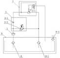
为解决这一技术问题,本发明提供了一种CAN信息综合控制液压风扇冷却系统,包括风扇、发动机、液压油泵、液压马达、组合阀、风扇轴承及托架、液压油箱和CAN信息综合控制器,发动机带动液压油泵工作,液压油泵的出口高压油经组合阀进入液压马达并驱动液压马达工作,液压马达通过风扇轴承及托架与风扇相联并带动风扇转动;所述的CAN信息综合控制器接受CAN线上发动机发送的水温、转速和油门踏板信号进行逻辑运算,通过输出电信号控制液压油泵及液压马达的流量,从而控制液压马达的输出转速,达到对风扇转速的控制,实现对发动机进行按需冷却。In order to solve this technical problem, the present invention provides a CAN information comprehensive control hydraulic fan cooling system, including fan, engine, hydraulic oil pump, hydraulic motor, combination valve, fan bearing and bracket, hydraulic oil tank and CAN information integrated controller , the engine drives the hydraulic oil pump to work, the outlet high pressure oil of the hydraulic oil pump enters the hydraulic motor through the combination valve and drives the hydraulic motor to work, the hydraulic motor is connected with the fan through the fan bearing and bracket and drives the fan to rotate; the CAN information integrated controller Accept the water temperature, speed and accelerator pedal signals sent by the engine on the CAN line to perform logic operations, and control the flow of the hydraulic oil pump and the hydraulic motor through the output electrical signal, thereby controlling the output speed of the hydraulic motor to achieve control of the fan speed and realize the engine. Cool as needed.
还设有空滤器,所述空滤器包括回油过滤器和吸油过滤器。An air filter is also provided, and the air filter includes an oil return filter and an oil suction filter.
所述的组合阀由控制液压油流向的单向阀和保持系统回路压力恒定的溢流阀组成。The combination valve is composed of a one-way valve for controlling the flow of hydraulic oil and an overflow valve for keeping the system circuit pressure constant.
所述液压油泵为比例变量液压油泵。The hydraulic oil pump is a proportional variable hydraulic oil pump.
所述液压马达为两级变量液压马达。The hydraulic motor is a two-stage variable hydraulic motor.
有益效果:本发明采用CAN信息综合控制器控制液压驱动,在整车布置时更加灵活,风扇可以布置在侧置放置,也可以布置在其他容易布置的位置,方便整车布置,还能够有效降低整车高度,增加车辆运输性;更重要的是风扇转速相对独立于发动机转速,可以在发动机大扭矩低转速的工况下,使风扇具有更高的冷却效率,并能根据发动机的水温、转速和油门踏板信号对风扇转速进行逻辑控制,实现对发动机按需冷却的目的,具有构思巧妙、技术先进、结构紧凑,使用安全、安装方便、节能环保、实用性强等特点。Beneficial effects: the present invention adopts the CAN information integrated controller to control the hydraulic drive, which is more flexible in the layout of the whole vehicle. The fan can be placed on the side or in other easy-to-arrange positions, which is convenient for the layout of the whole vehicle and can effectively reduce the The height of the vehicle increases the transportability of the vehicle; more importantly, the speed of the fan is relatively independent of the speed of the engine, which can make the fan have higher cooling efficiency under the condition of high torque and low speed of the engine. Logically control the fan speed with the accelerator pedal signal to achieve the purpose of cooling the engine on demand. It has the characteristics of ingenious conception, advanced technology, compact structure, safe use, convenient installation, energy saving and environmental protection, and strong practicability.
附图说明Description of drawings
图1为本发明的结构示意图;Fig. 1 is a structural representation of the present invention;
图2为本发明的液压原理图;Fig. 2 is a hydraulic principle diagram of the present invention;
图3为本发明的风扇连接示意图;Fig. 3 is a schematic diagram of fan connection of the present invention;
图4为本发明的工作流程图。Fig. 4 is a working flow diagram of the present invention.
图中:1液压油泵、2液压马达、3组合阀、3-1单向阀、3-2溢流阀、4风扇、5风扇轴承及托架、6液压油箱、7 CAN信息综合控制器、8发动机、9空滤器、9-1回油过滤器、9-2吸油过滤器。In the figure: 1 hydraulic oil pump, 2 hydraulic motor, 3 combination valve, 3-1 one-way valve, 3-2 overflow valve, 4 fan, 5 fan bearing and bracket, 6 hydraulic oil tank, 7 CAN information integrated controller, 8 engine, 9 air filter, 9-1 oil return filter, 9-2 oil suction filter.
具体实施方式Detailed ways
下面结合附图及实施例对本发明做具体描述。The present invention will be specifically described below in conjunction with the accompanying drawings and embodiments.
图1所示为本发明的结构示意图。Fig. 1 shows the structural representation of the present invention.
本发明包括风扇4和发动机8,液压油泵1、液压马达2、组合阀3、风扇轴承及托架5、液压油箱6和CAN信息综合控制器7。The present invention includes fan 4 and
图3所示为本发明的风扇连接示意图。Fig. 3 is a schematic diagram showing the connection of the fan of the present invention.
所述的风扇轴承及托架5支承风扇4,连接风扇4和液压马达2。The fan bearing and the
所述发动机8带动液压油泵1工作,液压油泵1的出口高压油经组合阀3进入液压马达2并驱动液压马达2工作,液压马达2带动风扇4转动。The
所述的CAN信息综合控制器7通过CAN线与发动机8相连,通过控制线分别与液压油泵1和液压马达2连接。The CAN information integrated controller 7 is connected with the
所述CAN信息综合控制器7接受CAN线上发动机8发送的水温、转速和油门踏板信号,根据所采集的信息进行逻辑运算,通过输出电信号来控制液压油泵1及液压马达2的流量,从而控制液压马达2的输出转速,达到对风扇4转速的控制,使冷却系统更加贴合发动机8实际工作状态,达到对发动机水温的精确控制,实现对发动机8进行按需冷却,起到节省燃料,节能环保的作用。The CAN information integrated controller 7 accepts the water temperature, rotating speed and accelerator pedal signal sent by the
the
图2所示为本发明的液压原理图。Fig. 2 shows the hydraulic principle diagram of the present invention.
本发明还设有空滤器9,所述空滤器9包括回油过滤器9-1和吸油过滤器9-2。The present invention is also provided with an
所述的组合阀3单向阀3-1和溢流阀3-2组成;所述单向阀3-1起到控制液压油流向的作用;溢流阀3-2主要起到溢流定压保持系统回路压力恒定的作用。The combined
所述液压油泵1为比例变量液压油泵。The
所述液压马达2为两级变量液压马达。The
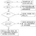
本发明的工作过程如下(如图4所示为本发明的工作流程图):Working process of the present invention is as follows (as shown in Figure 4 is the work flowchart of the present invention):
在发动机水温比较低的情况下(如设定小于83℃),为了尽快提高发动机水温,CAN信息综合控制器7对液压油泵1不输出电压,液压油泵1不运转,风扇4不转动;When the engine water temperature is relatively low (such as setting less than 83°C), in order to increase the engine water temperature as soon as possible, the CAN information integrated controller 7 does not output voltage to the
在发动机水温及发动机转速高于设定起始转速温度(如83℃)而低于高转速温度(如95℃)的情况下,液压油泵1根据温度的线性变化输出的流量也线性变化,液压油泵1的出口高压油首先通过组合阀3后进入液压马达2,并驱动液压马达2工作运转,相应地液压马达2根据输入的液压油流量相应输出线性的转速,液压马达2没有接收到控制信息,按普通流量运转,然后通过风扇轴承及托架5与风扇4相联,同时带动风扇4转动,风扇4的转速也根据温度的变化线性变化,这样可以根据水温控制满足发动机8这种工况下散热需求。When the engine water temperature and engine speed are higher than the set initial speed temperature (such as 83°C) but lower than the high speed temperature (such as 95°C), the output flow rate of the
当发动机水温大于设定的高转速温度(如95℃)时,并且小于水温报警温度(如103℃)时:如果发动机8不在低速大扭矩工况下工作(通过CAN信息控制器7按发动机转速和油门踏板信号进行判断),液压油泵1就输出最大流量,液压马达2以较高转速运转,可以满足散热效果;如果发动机8在低速大扭矩工况下工作,由于此时发动机8转速比较低,液压油泵1输出的流量也比较低,CAN信息综合控制器7给液压马达2发出控制信号,使液压马达2以小流量(高转速)工况下工作,进一步提高风扇4的转速,满足该种恶劣工况下发动机8散热需要量大的要求。When the engine water temperature is higher than the set high speed temperature (such as 95°C) and lower than the water temperature alarm temperature (such as 103°C): If the
本发明改变传统风扇由发动机曲轴带轮通过V带驱动的方式,采用CAN信息综合控制器控制液压驱动,在整车布置时更加灵活,风扇可以布置在侧置放置,也可以布置在其他容易布置的位置,方便整车布置,还能够有效降低整车高度,增加车辆运输性;更重要的是风扇转速相对独立与发动机转速,可以在发动机大扭矩低转速的工况下,使风扇具有更高的冷却效率,并能根据发动机的水温、转速和油门踏板信号对风扇转速进行逻辑控制,实现对发动机按需冷却的目的,节省燃料情况下达到节能环保性能,具有构思巧妙、技术先进、结构紧凑,使用安全、安装方便、节能环保、实用性强等特点。The invention changes the traditional way that the fan is driven by the crankshaft pulley of the engine through the V-belt, and adopts the CAN information integrated controller to control the hydraulic drive, which is more flexible in the layout of the vehicle. The fan can be placed on the side or other places that are easy to arrange The position is convenient for the layout of the whole vehicle, and it can also effectively reduce the height of the whole vehicle and increase the transportability of the vehicle; more importantly, the fan speed is relatively independent of the engine speed, which can make the fan have a higher performance under the condition of high torque and low speed of the engine. The cooling efficiency is high, and the fan speed can be logically controlled according to the engine's water temperature, speed and accelerator pedal signal, so as to achieve the purpose of cooling the engine on demand, and achieve energy saving and environmental protection performance while saving fuel. It has ingenious conception, advanced technology, and compact structure. , safe to use, easy to install, energy saving and environmental protection, strong practicability and so on.
本发明上述实施方案,只是举例说明,不是仅有的,所有在本发明范围内或等同本发明的范围内的改变均被本发明包围。The above-mentioned embodiments of the present invention are just examples, not the only ones, and all changes within the scope of the present invention or equivalent to the scope of the present invention are embraced by the present invention.
Claims (4)
Translated fromChinesePriority Applications (1)
| Application Number | Priority Date | Filing Date | Title |
|---|---|---|---|
| CN2013100238481ACN103075238A (en) | 2013-01-23 | 2013-01-23 | Hydraulic fan cooling system adopting CAN (controller area network) information integrated control |
Applications Claiming Priority (1)
| Application Number | Priority Date | Filing Date | Title |
|---|---|---|---|
| CN2013100238481ACN103075238A (en) | 2013-01-23 | 2013-01-23 | Hydraulic fan cooling system adopting CAN (controller area network) information integrated control |
Publications (1)
| Publication Number | Publication Date |
|---|---|
| CN103075238Atrue CN103075238A (en) | 2013-05-01 |
Family
ID=48151903
Family Applications (1)
| Application Number | Title | Priority Date | Filing Date |
|---|---|---|---|
| CN2013100238481APendingCN103075238A (en) | 2013-01-23 | 2013-01-23 | Hydraulic fan cooling system adopting CAN (controller area network) information integrated control |
Country Status (1)
| Country | Link |
|---|---|
| CN (1) | CN103075238A (en) |
Cited By (6)
| Publication number | Priority date | Publication date | Assignee | Title |
|---|---|---|---|---|
| CN103397927A (en)* | 2013-07-30 | 2013-11-20 | 贵州詹阳动力重工有限公司 | All-terrain vehicle independent temperature-control cooling system |
| CN104055207A (en)* | 2014-06-17 | 2014-09-24 | 洛阳四达农机有限公司 | Cooling system of silaging machine |
| CN105074157A (en)* | 2015-03-27 | 2015-11-18 | 株式会社小松制作所 | Working vehicle |
| CN107097634A (en)* | 2017-05-03 | 2017-08-29 | 江苏柳工机械有限公司 | A kind of sliding loader independence cooling system |
| CN108644001A (en)* | 2018-07-13 | 2018-10-12 | 安徽合力股份有限公司 | A kind of the intelligent heat dissipation system and its heat dissipating method of hydraulic motor driving |
| CN114233460A (en)* | 2021-12-28 | 2022-03-25 | 徐州徐工矿业机械有限公司 | Independent heat dissipation control system and method for engineering machinery |
Citations (8)
| Publication number | Priority date | Publication date | Assignee | Title |
|---|---|---|---|---|
| JPH10212952A (en)* | 1997-01-30 | 1998-08-11 | Nissan Diesel Motor Co Ltd | Hydraulic control type fan driving system |
| US20060196720A1 (en)* | 2005-03-07 | 2006-09-07 | Zahniser John C | Hydraulic steering system with input horsepower limiting circuit and increased fan speeds at low engine RPM |
| JP2009250081A (en)* | 2008-04-03 | 2009-10-29 | Tcm Corp | Cooling fan driving circuit and wheel loader of wheel type working vehicle |
| CN101851941A (en)* | 2010-04-16 | 2010-10-06 | 山推工程机械股份有限公司 | Cooling control system of fan of bulldozer |
| CN102322329A (en)* | 2011-08-17 | 2012-01-18 | 上海三一重机有限公司 | Intelligent control method of engine cooling fan for engineering machinery |
| CN202370867U (en)* | 2011-12-09 | 2012-08-08 | 中国重汽集团济南动力有限公司 | Radiating hydraulic device for fan |
| CN202560603U (en)* | 2012-04-10 | 2012-11-28 | 中国重汽集团济南动力有限公司 | Fan control system |
| CN203022861U (en)* | 2013-01-23 | 2013-06-26 | 中国重汽集团济南动力有限公司 | Hydraulic fan cooling system based on CAN (controller area network) information comprehensive control |
- 2013
- 2013-01-23CNCN2013100238481Apatent/CN103075238A/enactivePending
Patent Citations (8)
| Publication number | Priority date | Publication date | Assignee | Title |
|---|---|---|---|---|
| JPH10212952A (en)* | 1997-01-30 | 1998-08-11 | Nissan Diesel Motor Co Ltd | Hydraulic control type fan driving system |
| US20060196720A1 (en)* | 2005-03-07 | 2006-09-07 | Zahniser John C | Hydraulic steering system with input horsepower limiting circuit and increased fan speeds at low engine RPM |
| JP2009250081A (en)* | 2008-04-03 | 2009-10-29 | Tcm Corp | Cooling fan driving circuit and wheel loader of wheel type working vehicle |
| CN101851941A (en)* | 2010-04-16 | 2010-10-06 | 山推工程机械股份有限公司 | Cooling control system of fan of bulldozer |
| CN102322329A (en)* | 2011-08-17 | 2012-01-18 | 上海三一重机有限公司 | Intelligent control method of engine cooling fan for engineering machinery |
| CN202370867U (en)* | 2011-12-09 | 2012-08-08 | 中国重汽集团济南动力有限公司 | Radiating hydraulic device for fan |
| CN202560603U (en)* | 2012-04-10 | 2012-11-28 | 中国重汽集团济南动力有限公司 | Fan control system |
| CN203022861U (en)* | 2013-01-23 | 2013-06-26 | 中国重汽集团济南动力有限公司 | Hydraulic fan cooling system based on CAN (controller area network) information comprehensive control |
Cited By (8)
| Publication number | Priority date | Publication date | Assignee | Title |
|---|---|---|---|---|
| CN103397927A (en)* | 2013-07-30 | 2013-11-20 | 贵州詹阳动力重工有限公司 | All-terrain vehicle independent temperature-control cooling system |
| CN104055207A (en)* | 2014-06-17 | 2014-09-24 | 洛阳四达农机有限公司 | Cooling system of silaging machine |
| CN105074157A (en)* | 2015-03-27 | 2015-11-18 | 株式会社小松制作所 | Working vehicle |
| US9945101B2 (en) | 2015-03-27 | 2018-04-17 | Komatsu Ltd. | Work vehicle |
| CN107097634A (en)* | 2017-05-03 | 2017-08-29 | 江苏柳工机械有限公司 | A kind of sliding loader independence cooling system |
| CN108644001A (en)* | 2018-07-13 | 2018-10-12 | 安徽合力股份有限公司 | A kind of the intelligent heat dissipation system and its heat dissipating method of hydraulic motor driving |
| CN108644001B (en)* | 2018-07-13 | 2024-02-09 | 安徽合力股份有限公司 | Intelligent heat dissipation system driven by hydraulic motor and heat dissipation method thereof |
| CN114233460A (en)* | 2021-12-28 | 2022-03-25 | 徐州徐工矿业机械有限公司 | Independent heat dissipation control system and method for engineering machinery |
Similar Documents
| Publication | Publication Date | Title |
|---|---|---|
| CN103075238A (en) | Hydraulic fan cooling system adopting CAN (controller area network) information integrated control | |
| CN202156297U (en) | Power take-off device of hydraulic pump | |
| CN204488420U (en) | The a/c system of a kind of motor vehicle driven by mixed power and double dynamical driving air-conditioning compressor thereof | |
| CN201729056U (en) | Heat-radiating system for engineering machinery and engineering machinery | |
| CN205686163U (en) | Electric automobile water-cooling control system | |
| CN203114404U (en) | Forklift engine cooling system utilizing static hydraulic pressure to drive fan | |
| CN204041199U (en) | The automatically controlled auxiliary coolant system of a kind of motor combined type | |
| CN204082299U (en) | A kind of automobile cooling heat dissipation fan control system | |
| CN109910852A (en) | A vehicle cooling system with hydraulic and electric retarder | |
| CN207525807U (en) | A kind of hydraulic drive circuit for excavator cooling system | |
| CN202560603U (en) | Fan control system | |
| CN203022861U (en) | Hydraulic fan cooling system based on CAN (controller area network) information comprehensive control | |
| CN105438257A (en) | Electric Auxiliary Systems for Hybrid Vehicles | |
| CN202065045U (en) | Rotation speed control system for cooling fan of automobile engine | |
| CN104265439A (en) | Engineering machinery cooling system | |
| CN205714394U (en) | novel hybrid power assembly cooling system | |
| CN203699690U (en) | Engineering machine and heat dissipation system thereof | |
| CN203476477U (en) | Heat dissipation control system of vehicle engine | |
| CN202954876U (en) | Energy-saving heat dissipation system for engineering machinery | |
| CN205779194U (en) | Electromagnetic clutch fan control system | |
| CN203270657U (en) | Novel radiating device of hydraulic excavator | |
| CN201132969Y (en) | Stall protective system of hydraulic moment changer special for bulldozers | |
| CN204804925U (en) | Engine electron fan control system | |
| CN210003378U (en) | A vehicle engine cooling system, engine and vehicle | |
| CN209976613U (en) | Heat dissipation system for heavy commercial vehicle |
Legal Events
| Date | Code | Title | Description |
|---|---|---|---|
| C06 | Publication | ||
| PB01 | Publication | ||
| C10 | Entry into substantive examination | ||
| SE01 | Entry into force of request for substantive examination | ||
| C02 | Deemed withdrawal of patent application after publication (patent law 2001) | ||
| WD01 | Invention patent application deemed withdrawn after publication | Application publication date:20130501 |