CN103070713A - Axial force controllable surgical bone drill adopting brazed PCBN (polycrystalline cubic boron nitride) superhard material drill bit - Google Patents
Axial force controllable surgical bone drill adopting brazed PCBN (polycrystalline cubic boron nitride) superhard material drill bitDownload PDFInfo
- Publication number
- CN103070713A CN103070713ACN2013100108524ACN201310010852ACN103070713ACN 103070713 ACN103070713 ACN 103070713ACN 2013100108524 ACN2013100108524 ACN 2013100108524ACN 201310010852 ACN201310010852 ACN 201310010852ACN 103070713 ACN103070713 ACN 103070713A
- Authority
- CN
- China
- Prior art keywords
- drill
- drill bit
- axial force
- superhard material
- casing
- Prior art date
- Legal status (The legal status is an assumption and is not a legal conclusion. Google has not performed a legal analysis and makes no representation as to the accuracy of the status listed.)
- Granted
Links
Images


Landscapes
- Surgical Instruments (AREA)
Abstract
Translated fromChineseDescription
Translated fromChinese技术领域technical field
本发明涉及一种医疗器械,具体的为一种采用钎焊PCBN超硬材料钻头的轴向力可控的外科骨钻。 The invention relates to a medical device, in particular to a surgical bone drill adopting a brazed PCBN superhard material drill bit with controllable axial force. the
背景技术Background technique
目前外科头骨钻孔的器械为手持式电动钻,手持式电动钻的操作方式为:由医师徒手扶持电钻来控制钻孔方向与进给量。电钻设计有一组安全装置,动力源通过离合器与钻头相连接,当钻头承受压力会使钻头通过离合器与动力源相连,带动钻头运转以进行骨钻孔操作;当钻头钻穿头骨时,因不再承受头骨的反作用力会使钻头与动力源分离,使电钻停止运转。然而这些方法均须凭借医师个人丰富的临床经验与手部感觉来判断骨钻孔的过程中是否已穿越头骨,并手动迅速停止;若是经由缺乏丰富经验的医师执行时,即使有上述特殊安全装置的电钻,稍有不慎也有可能在穿越头骨的同时伤及头骨下方的脑膜及神经组织。此外采用徒手方式钻孔,亦可能因为手臂力量不足导致钻孔过程产生震动,影响钻孔过程的安全性、准确性与舒适性。 The instrument of surgical skull drilling is a hand-held electric drill at present, and the operation mode of the hand-held electric drill is: the electric drill is supported by the physician with bare hands to control the drilling direction and the feed rate. The electric drill is designed with a set of safety devices. The power source is connected to the drill bit through a clutch. When the drill bit is under pressure, the drill bit will be connected to the power source through the clutch to drive the drill bit to perform bone drilling operations; Bearing the reaction force of the skull can separate the drill bit from the power source, stopping the drill. However, these methods must rely on the doctor's personal rich clinical experience and hand feeling to judge whether the bone drilling process has passed through the skull, and manually stop it quickly; If you are not careful, you may injure the meninges and nerve tissues below the skull while passing through the skull. In addition, when drilling holes by hand, insufficient arm strength may cause vibration during the drilling process, which affects the safety, accuracy and comfort of the drilling process. the
为了增加外科骨钻孔过程中的安全性和准确性,“一种智能骨钻及其控制方法”(中国专利号为2009101036423)发明专利公开了在骨钻电机上设置有应变式扭矩传感器、转速传感器或压力传感器的任意一种、两种或三种传感器件;在骨钻电机上还设置有嵌入式智能测控模块接收传感器采集的感应信号并进行判断,控制骨钻电机。但这种方法是在骨钻电机的基体上设置转速传感器、扭矩传感器以及压力传感器对钻头转速、扭矩和压力进行实时测量。显然这种测量方法的精度和准确性不能保证要求,因为骨钻电机的基体上受各种信号及其复杂,信号的采集和处理精度和准确性很难得到保证,再加上从钻头的受力点到动力源电机,传动链比较长,测试的精度和准确性也不能满足要求。 In order to increase the safety and accuracy in the process of surgical bone drilling, the invention patent of "An Intelligent Bone Drill and Its Control Method" (Chinese Patent No. Any one, two or three sensor components of sensors or pressure sensors; an embedded intelligent measurement and control module is also provided on the bone drill motor to receive the induction signals collected by the sensor and make judgments to control the bone drill motor. However, this method is to arrange a speed sensor, a torque sensor and a pressure sensor on the base body of the bone drill motor to measure the drill bit speed, torque and pressure in real time. Obviously, the precision and accuracy of this measurement method cannot guarantee the requirements, because the base body of the bone drill motor is subjected to various signals and its complexity, and the accuracy and accuracy of signal acquisition and processing are difficult to be guaranteed. From the power point to the power source motor, the transmission chain is relatively long, and the precision and accuracy of the test cannot meet the requirements. the
发明内容Contents of the invention
本发明的目的就是为解决上述问题,提供一种采用钎焊PCBN超硬材料钻头的轴向力可控的外科骨钻,它控制的精确度高,可有效避免对脑组织的损伤。 The purpose of the present invention is to solve the above problems, to provide a surgical bone drill adopting brazed PCBN superhard material drill bit with controllable axial force, which has high control accuracy and can effectively avoid damage to brain tissue. the
为实现上述目的,本发明采用如下技术方案: To achieve the above object, the present invention adopts the following technical solutions:
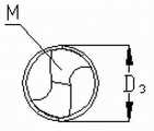
一种采用钎焊PCBN超硬材料钻头的轴向力可控的外科骨钻,它包括钻体和钻头,所述钻体包括机壳,在机壳内设有直流电机,直流电机与智能集成控制系统和直流电源连接,直流电机的输出轴与齿轮传动装置连接,齿轮传动装置通过传动轴与钻头夹头连接,钻头安装在 钻头夹头上;在钻头夹头与传动轴的连接处设有推力轴承,推力轴承紧贴变形元件,变形元件紧靠在机壳上,变形元件用弹性元件定位,电阻应变片粘贴在变形元件内表面,电阻应变片还与智能集成控制系统连接,钻头夹头与机壳间则设有密封装置;所述钻头包括一个圆柱基体,圆柱基体设有麻花钻尖,在圆柱基体上还设有螺旋槽,在螺旋槽和钻头主后刀面M设有PCBN超硬材料。 A surgical bone drill with controllable axial force using a brazed PCBN superhard material drill bit, which includes a drill body and a drill bit, the drill body includes a casing, and a DC motor is arranged in the casing, and the DC motor is integrated with an intelligent The control system is connected to the DC power supply, the output shaft of the DC motor is connected to the gear transmission device, the gear transmission device is connected to the drill chuck through the transmission shaft, and the drill bit is installed on the drill chuck; Thrust bearing, the thrust bearing is close to the deformation element, the deformation element is close to the casing, the deformation element is positioned by the elastic element, the resistance strain gauge is pasted on the inner surface of the deformation element, the resistance strain gauge is also connected with the intelligent integrated control system, the drill chuck There is a sealing device between the casing and the casing; the drill bit includes a cylindrical base body, the cylindrical base body is provided with a twist drill tip, and a spiral groove is also arranged on the cylindrical base body, and a PCBN superstructure is arranged on the spiral groove and the main flank M of the drill bit. hard material. the
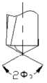
所述钻头总长L3,工作部分长度l3,钻头的钻柄部分采用直柄形式,钻头采用不锈钢制成:首先在圆柱基体一端加工出麻花钻尖部分,然后再在圆柱基体圆柱表面上加工一个宽度为H3,深度为h3的螺旋槽,螺旋槽的宽度H3根据钻头直径和需要的不同而改变,其变化范围为0.5mm—5mm,深度h3根据钻头直径和超硬材料的宽度的变化在0.2mm—2mm之间选择。螺旋槽的螺旋角β3的变化范围在18°—30°之间;螺旋槽加工完成后,将PCBN超硬材料切割成和钻头主后刀面M和螺旋槽形状相同的板材,然后用钎焊的方法将切割好的PCBN超硬材料钎焊在钻头主后刀面M和螺旋槽中,这时切削刃突出基体的高度为ht3,根据不锈钢基体的直径d3和切削刃的突出高度ht3可钻头的直径D3控制在2mm—10mm。 The total length of the drill bit is L3 , the length of the working part is l3 , the drill shank of the drill bit is in the form of a straight shank, and the drill bit is made of stainless steel: first, the twist drill tip is processed at one end of the cylindrical base, and then processed on the cylindrical surface of the cylindrical base A spiral groove with a width of H3 and a depth of h3. The width of the spiral groove H3 varies according to the diameter of the drill bit and the needs, and the range of variation is 0.5mm-5mm. The depth h3 depends on the diameter of the drill bit and the superhard material The change of width is selected between 0.2mm-2mm. The helix angleβ3 of the helical groove varies between 18°-30°; after the helical groove is processed, the PCBN superhard material is cut into a plate with the same shape as the main flank M of the drill bit and the helical groove, and then brazed The welding method is to braze the cut PCBN superhard material on the main flank M of the drill bit and the spiral groove. At this time, the height of the cutting edge protruding from the base is ht3 . According to the diameter d3 of the stainless steel base and the protruding height of the cutting edge ht3 can control the diameter D3 of the drill bit at 2mm-10mm.
所述智能集成控制系统包括单片机,单片机通过开关控制电路与直流电机和控制开关连接;同时单片机还依次与A/D转换器、信号采集器、放大器、滤波器、电桥电路连接,电桥电路与电阻应变片连接;信号采集器对测量的电压信号进行采集,然后经A/D转换器转换成数字量输入到单片机中,判断是否满足自停条件:钻头在钻穿骨头瞬间轴向力会突然下降,并且以后的轴向力会很小并基本保持不变,所以判断钻穿的依据就是所采集到的电压信号的斜率小于一个设定好的很小的值并基本保持不变,此时单片机即判断满足自停条件,即会发出信号切断开关控制电路,从而实现自停功能; Described intelligent integrated control system comprises single-chip microcomputer, and single-chip microcomputer is connected with DC motor and control switch through switch control circuit; It is connected with the resistance strain gauge; the signal collector collects the measured voltage signal, and then converts it into a digital quantity through the A/D converter and inputs it into the single-chip microcomputer to judge whether the self-stop condition is met: the axial force of the drill bit will decrease when the drill bit penetrates the bone. The sudden drop, and the axial force will be very small and remain basically unchanged in the future, so the basis for judging drilling through is that the slope of the collected voltage signal is less than a set small value and remains basically unchanged. When the single-chip microcomputer judges that the self-stop condition is met, it will send a signal to cut off the switch control circuit, thereby realizing the self-stop function;
同时,单片机根据信号采集装置采集的电压信号判断轴向力是否过大,判断轴向力过大的依据是:所采集的电压信号大于某个设定好的值,这时单片机即判断此时轴向力过大。 At the same time, the single-chip microcomputer judges whether the axial force is too large according to the voltage signal collected by the signal acquisition device. Excessive axial force. the
所述齿轮传动装置包括一个与直流电机输出轴通过凹凸槽连接的主动齿轮轴,主动齿轮轴两端分别与深沟球轴承Ⅰ和深沟球轴承Ⅱ连接进行定位,并且两个轴承均靠轴肩和机壳实现定位;主动齿轮轴与从动齿轮啮合,从动齿轮通过平键与从动轴连接,从动齿轮靠轴肩和轴套Ⅰ实现轴向定位,从动轴两端对称安装有深沟球轴承Ⅲ和深沟球轴承Ⅳ,深沟球轴承Ⅲ用止动螺母Ⅱ、轴肩和机壳来定位,深沟球轴承Ⅳ用轴套Ⅰ、止动螺母Ⅰ和机壳定位;从动轴和传动轴通过凹凸槽相连。 The gear transmission device includes a driving gear shaft connected to the output shaft of the DC motor through a concave-convex groove, and the two ends of the driving gear shaft are respectively connected to the deep groove ball bearing I and the deep groove ball bearing II for positioning. The shoulder and the casing realize positioning; the driving gear shaft meshes with the driven gear, and the driven gear is connected to the driven shaft through a flat key. There are deep groove ball bearing Ⅲ and deep groove ball bearing Ⅳ, deep groove ball bearing Ⅲ is positioned by stop nut Ⅱ, shaft shoulder and casing, deep groove ball bearing Ⅳ is positioned by shaft sleeve Ⅰ, stop nut Ⅰ and casing ; The driven shaft and the transmission shaft are connected through concave-convex grooves. the
所述传动轴设有轴套Ⅱ,从动轴两端分别安装在深沟球轴承Ⅴ和深沟球轴承Ⅵ上。 The drive shaft is provided with a shaft sleeve II, and the two ends of the driven shaft are installed on deep groove ball bearings V and VI respectively. the
所述密封装置为嵌在机壳上的密封圈。 The sealing device is a sealing ring embedded in the casing. the
本发明提供一种采用钎焊PCBN超硬材料钻头的轴向力可控的外科骨钻及其钻头,在钻孔的过程中,轴向力传递路线是骨头作用在钻头上,钻头传递给钻头夹头,钻头夹头传递给传动轴,传动轴传传递给推力轴承,推力轴承传递给变形元件,这样就引起变形元件发生形变,导致电阻应变片的形变,这样轴向力大小就转化为电阻应变片形变量的大小。电阻应变片的形变会使其电阻值发生改变,经过电桥电路后转换为微小的电压值,然后经滤波器进行滤波,排出干扰信号后,再经放大器放大、信号采集器采集信号以及A/D转换器36转换后即可被单片机识别,对工况进行判断。 The invention provides a surgical bone drill with controllable axial force and its drill bit adopting brazed PCBN superhard material drill bit. During the drilling process, the axial force transmission route is that the bone acts on the drill bit, and the drill bit is transmitted to the drill bit. The chuck and drill chuck are transmitted to the transmission shaft, the transmission shaft is transmitted to the thrust bearing, and the thrust bearing is transmitted to the deformation element, which causes the deformation of the deformation element, resulting in the deformation of the resistance strain gauge, so that the axial force is converted into resistance The size of the deformation of the strain gauge. The deformation of the resistance strain gauge will change its resistance value, which will be converted into a tiny voltage value after passing through the bridge circuit, and then filtered by the filter to discharge the interference signal, and then amplified by the amplifier, the signal collector collects the signal and A/ The
在钻孔时,可能由于骨头碎片的塑性变形和钻头与骨头间的摩擦力而造成温度升高。骨钻孔过程中可能会引发骨坏死,钻孔邻近区域的骨细胞由于钻孔温度超过50℃临界值时会导致永久性死亡。为了降低钻孔温度,钻孔过程尽可能快已防止热量传入到骨邻近组织中。通过增加轴向力可以使钻孔速度提高。然而,轴向力过大,可能引起病人的进一步骨折和钻削温度的提高。通过改变钻孔参数来调整轴向力和钻孔温度显然不能从根本上解决问题。本发明采用在骨钻基体表面上钎焊金刚石,并实现金刚石磨粒的可控有序排布。磨粒的裸露高度可达70﹪—80﹪,因此相当于用金刚石磨粒代理骨钻的切削刃完成钻孔操作,因此可大大降低钻削力,从而降低钻削温度。 During drilling, there may be an increase in temperature due to plastic deformation of the bone fragments and friction between the drill bit and the bone. Osteonecrosis may occur during bone drilling, and the bone cells in the vicinity of the drilling will die permanently when the drilling temperature exceeds the critical value of 50°C. In order to reduce the drilling temperature, the drilling process is performed as quickly as possible to prevent the transfer of heat into the adjacent tissue of the bone. The drilling speed can be increased by increasing the axial force. However, excessive axial force may cause further fracture of the patient and increase of drilling temperature. Adjusting the axial force and drilling temperature by changing the drilling parameters obviously cannot fundamentally solve the problem. The invention adopts the brazing of diamond on the surface of the bone drill matrix, and realizes the controllable and orderly arrangement of the diamond abrasive grains. The exposed height of the abrasive grains can reach 70%-80%, so it is equivalent to using diamond abrasive grains as a substitute for the cutting edge of the bone drill to complete the drilling operation, so the drilling force can be greatly reduced, thereby reducing the drilling temperature. the
本发明的有益效果是:在骨钻传动轴的前轴承即推力轴承上设置有变形元件和电阻应变片,从而监测钻削过程中的钻削力,由于前轴承直接在钻头受力点附近,信号的监测和传输比较准确,精度高,可有效防止轴向力过大或骨钻穿时对骨组织的伤害。钻头的切削刃采用PCBN超硬材料,这种材料大大提高了切削刃的锋利程度,减小了钻孔轴向力,从而降低了钻削温度;钻头的螺旋角的变化范围选择在18°—30°之间,能够保证切屑能够及时顺利排出,带走热量,降低温升;螺旋槽的宽度H3根据钻头直径和需要的不同而改变,其变化范围为0.5mm—5mm,这一范围能够适应不同钻孔直径的加工要求;用于钎焊PCBN超硬材料的螺纹槽深度控制在0.2mm—2mm之间,这个深度即能保证不损害钻头基体的强度又能保证钎焊PCBN超硬材料的稳定性。 The beneficial effects of the present invention are: the front bearing of the bone drill drive shaft, that is, the thrust bearing, is provided with deformation elements and resistance strain gauges, so as to monitor the drilling force in the drilling process. Since the front bearing is directly near the force point of the drill bit, The monitoring and transmission of the signal are relatively accurate and the precision is high, which can effectively prevent damage to the bone tissue when the axial force is too large or the bone is drilled through. The cutting edge of the drill bit is made of PCBN superhard material, which greatly improves the sharpness of the cutting edge, reduces the axial force of the drilling hole, and thus reduces the drilling temperature; the helix angle of the drill bit varies from 18° to Between 30°, it can ensure that the chips can be discharged smoothly in time, take away the heat, and reduce the temperature rise; the width H3 of the spiral groove varies according to the diameter of the drill bit and the needs, and the range of variation is 0.5mm-5mm, which can be adapted to The processing requirements of different drilling diameters; the depth of the thread groove used for brazing PCBN superhard materials is controlled between 0.2mm and 2mm. This depth can not only ensure that the strength of the drill bit substrate is not damaged, but also ensure the brazing of PCBN superhard materials. stability. the
附图说明Description of drawings
图1为外科骨钻孔自停降温电钻的剖视图; Fig. 1 is the sectional view of surgical bone drilling self-stop cooling electric drill;
图2为智能集成控制系统部件; Figure 2 is the components of the intelligent integrated control system;
图3为轴向力传递框图; Figure 3 is a block diagram of axial force transmission;
图4为轴向力检测控制框图; Figure 4 is a block diagram of axial force detection control;
图4a为轴向力检测控制框图; Figure 4a is a block diagram of axial force detection control;
图5为钻穿自停功能控制框图; Figure 5 is a control block diagram of the drill through self-stop function;
图5a为钻穿自停功能控制框图; Figure 5a is a control block diagram of the drill through self-stop function;
图6为轴向力过大控制框图; Figure 6 is a block diagram of excessive axial force control;
图6a为轴向力过大控制框图; Figure 6a is a block diagram of excessive axial force control;
图7为骨钻孔钻头; Fig. 7 is bone drill bit;
图7a为钻头正面视图; Figure 7a is a drill bit front view;
图7b为螺旋槽位置图; Figure 7b is a diagram of the position of the spiral groove;
图7c为钻尖角度图; Figure 7c is a drill tip angle diagram;
图7d为图7中B-B向放大图; Figure 7d is an enlarged view of B-B in Figure 7;
图7e为螺旋槽结构图。 Fig. 7e is a structural diagram of a spiral groove. the
其中,1-直流电源,2-控制开关,3-主动齿轮轴,4-机壳,5-直流电机,6-从动轴,7-智能集成控制系统,8-平键,9-从动齿轮,10-轴套Ⅰ,11-轴套Ⅱ,12-止动螺母Ⅰ,13-传动轴,14-电阻应变片,15-弹性元件,16-变形元件,17-推力轴承,18-密封圈,19-钻头夹头,20-钻头,21-深沟球轴承Ⅰ,22-深沟球轴承Ⅱ,23-深沟球轴承Ⅲ,24-深沟球轴承Ⅳ,25-深沟球轴承Ⅴ,26-深沟球轴承Ⅵ,27-止动螺母Ⅱ,28-止动螺母Ⅲ,29-直流电机底座,30-直流电源底盖,31-螺纹孔,32-电桥电路,33-滤波器,34-放大器,35-信号采集器,36-A/D转换器,37-单片机,38-开关控制电路。 Among them, 1-DC power supply, 2-control switch, 3-driving gear shaft, 4-casing, 5-DC motor, 6-driven shaft, 7-intelligent integrated control system, 8-flat key, 9-driven Gear, 10-shaft sleeve Ⅰ, 11-shaft sleeve Ⅱ, 12-stop nut Ⅰ, 13-transmission shaft, 14-resistance strain gauge, 15-elastic element, 16-deformation element, 17-thrust bearing, 18-seal Ring, 19-drill chuck, 20-drill, 21-deep groove ball bearing Ⅰ, 22-deep groove ball bearing Ⅱ, 23-deep groove ball bearing Ⅲ, 24-deep groove ball bearing Ⅳ, 25-deep groove ball bearing Ⅴ, 26-deep groove ball bearing Ⅵ, 27-stop nut Ⅱ, 28-stop nut Ⅲ, 29-DC motor base, 30-DC power supply bottom cover, 31-threaded hole, 32-bridge circuit, 33- Filter, 34-amplifier, 35-signal collector, 36-A/D converter, 37-single-chip microcomputer, 38-switch control circuit. the
具体实施方式Detailed ways
下面结合附图与实施例对本发明做进一步说明。 The present invention will be further described below in conjunction with the accompanying drawings and embodiments. the
图1显示了外科骨钻孔自停降温电钻的各组成部分,其中机壳4由对称的上下两半构成,并由螺钉通过螺纹孔31相固定。直流电源1与控制开关2用导线相连,结合图2可知,控制开关2和智能集成控制系统7中的开关控制电路38用导线相连,开关控制电路38和直流电机5用导线连接。直流电机5固定在直流电机底座29上。直流电机5和主动齿轮轴3通过凹凸槽相连,主动齿轮轴3安装在深沟球轴承Ⅰ21和深沟球轴承Ⅱ22上来实现定位,并且两个轴承均靠轴肩和机壳4实现定位,主动齿轮轴3和从动齿轮9相啮合,从动齿轮9通过平键8和从动轴6相配合。从动齿轮9靠轴肩和轴套Ⅰ10实现轴向定位,从动轴6两端对称安装有深沟球轴承Ⅲ23和深沟球轴承Ⅳ24,深沟球轴承Ⅲ23用止动螺母Ⅱ27、轴肩和机壳4来定位,深沟球轴承Ⅳ24用轴套Ⅰ10、止动螺母Ⅰ和机壳4定位。从动轴6和传动轴13凹凸槽相连,传动轴6两端安装有深沟球轴承Ⅴ25和深沟球轴承Ⅵ26来实现定位,深沟球轴承Ⅴ25依靠止动螺母Ⅲ28、轴套Ⅱ11和机壳4定位,深沟球轴承Ⅵ26用轴肩、轴套Ⅱ11和机壳4定位。传动轴13的另一端的轴肩处安装有一推力轴承17,推力轴承17紧贴变形元件16,变形元件16另一端紧靠在机壳4上,变形元件16用弹性元件15定位,电阻应变片14粘贴在变形元件16内表面。结合图2可得,电阻应变片14与智能集成控制系统7中的电桥电路用 导线相连。钻头夹头19固定在传动轴末端,钻头夹头19用来夹紧钻头20。密封圈18嵌在机壳中起密封作用,直流电源底盖30紧扣在机壳4上。 Fig. 1 has shown the various components of the self-stop cooling electric drill for surgical bone drilling, wherein the
由图2可知,智能集成控制系统7由电桥电路32,滤波器33,放大器34,信号采集器35,A/D转换器36,单片机37,开关控制电路38集合而成。其中,电阻应变片14和电桥电路32用导线相连,电桥电路32和滤波器33连通,滤波器33和放大器34相连,放大器34和信号采集器35相连,信号采集器35和A/D转换器36相连,A/D转换器36和单片机37相连,单片机37和和开关控制电路38相连,开关控制电路38分别和直流电机5和控制开关2用导线相连。 As can be seen from FIG. 2 , the intelligent
由图3可得,在钻孔的过程中,轴向力传递路线是骨头作用在钻头20上,钻头20传递给钻头夹头19,钻头夹头19传递给传动轴13,传动轴传13传递给推力轴承17,推力轴承17传递给变形元件16,这样就引起变形元件16发生形变,导致电阻应变片14的形变,这样轴向力大小就转化为电阻应变片14形变量的大小。 It can be seen from Figure 3 that during the drilling process, the axial force transmission route is that the bone acts on the
由图4、图4a可得电阻应变片14的形变会使其电阻值发生改变,经过电桥电路32后转换为微小的电压值,然后经滤波器33进行滤波,排出干扰信号后,再经放大器34放大、信号采集器35采集信号以及A/D转换器36转换后即可被单片机37识别,对工况进行判断。 From Figure 4 and Figure 4a, it can be seen that the deformation of the
由图5、图5a可知,电钻工作中,信号采集器对测量的电压信号进行采集,然后经A/D转换器36转换成数字量输入到单片机37中判断是否满足自停条件,如果满足自停条件,那么单片机37会发送指令使开关控制电路38断路,实现自停功能。因为钻头在钻穿骨头瞬间轴向力会突然下降,并且以后的轴向力会很小并基本保持不变,所以判断钻穿的依据就是所采集到的电压信号的斜率小于一个设定好的很小的值并基本保持不变,此时单片机37即判断满足自停条件,即会发出信号切断开关控制电路38,从而实现自停功能。 It can be seen from Fig. 5 and Fig. 5a that during the operation of the electric drill, the signal collector collects the measured voltage signal, and then converts it into a digital quantity through the A/
由图6、图6a可知,采集到的电压信号经A/D转换器36转换后被单片机37接收,单片机37如果判断此时轴向力过大,单片机就会向开关控制电路38发出指令,减小电流,从而将轴向力控制在正常范围内。判断轴向力过大的依据是所采集的电压信号大于某个设定好的值,这时单片机37即判断此时轴向力过大。 It can be seen from Fig. 6 and Fig. 6a that the collected voltage signal is converted by the A/
图7、图7a-7e所示,由图可得,这种钻头总长L3,工作部分长度l3,钻头的钻柄部分采用直柄形式,钻尖部分和普通直柄麻花钻的钻尖部分相似,其余钻头的钻杆部分在圆柱基体表面上加工而成,钻头的基体材料采用不锈钢。具体制作方法:首先在圆柱基体一端加工出和普通麻花钻钻尖形状相同的钻尖部分,钻尖的形状参数和标准麻花钻钻尖参数一致,然后再在圆柱基体圆柱表面上加工一个宽度为H3,深度为h3的螺旋槽,螺旋槽的宽度H3可根据钻头直径和需要的不同而改变,其变化范围为0.5mm—5mm,深度h3根据钻头直径和PCBN超硬 材料的宽度的变化在0.2mm—2mm之间选择,这个深度即能保证不损害钻头基体的强度又能保证钎焊PCBN超硬材料的稳定性。螺旋槽的螺旋角β3的变化范围在18°—30°之间,能够保证切屑能够及时顺利排出,带走热量,降低温升;螺旋槽加工完成后,就将PCBN超硬材料切割成和钻头主后刀面M和螺旋槽形状相同的板材,然后用钎焊的方法将切割好的PCBN超硬材料钎焊在钻头主后刀面M和螺旋槽中,这种材料大大提高了切削刃的锋利程度,减小了钻孔轴向力,从而降低了钻削温度;这时切削刃突出基体的高度为ht3,根据不锈钢基体的直径d3和切削刃的突出高度ht3可将钻头的直径D3控制在2mm—10mm。 As shown in Figure 7 and Figure 7a-7e, it can be seen from the figure that the total length of this drill is L3 , the length of the working part is l3 , the drill shank of the drill is in the form of a straight shank, and the drill tip is the same as the drill tip of an ordinary straight shank twist drill Partially similar, the drill pipe part of the rest of the drill bit is processed on the surface of the cylindrical base body, and the base material of the drill bit is made of stainless steel. The specific production method: first process a drill tip part with the same shape as the ordinary twist drill tip at one end of the cylindrical base body, and the shape parameters of the drill tip are consistent with the standard twist drill tip parameters, and then process a width of H3 , a spiral groove with a depth of h3 , the width of the spiral groove H3 can be changed according to the diameter of the drill bit and the needs, and the range of variation is 0.5mm-5mm, and the depth h3 is based on the diameter of the drill bit and the width of the PCBN superhard material The change of the drill bit is selected between 0.2mm-2mm. This depth can not only ensure the strength of the drill bit substrate but also ensure the stability of the brazing PCBN superhard material. The variation range of the helix angleβ3 of the spiral groove is between 18°-30°, which can ensure that the chips can be discharged smoothly in time, take away the heat, and reduce the temperature rise; after the spiral groove is processed, the PCBN superhard material is cut into and The plate with the same shape as the main flank M of the drill bit and the spiral groove, and then braze the cut PCBN superhard material in the main flank M of the drill bit and the spiral groove by brazing method, this material greatly improves the cutting edge The sharpness reduces the drilling axial force, thereby reducing the drilling temperature; at this time, the height of the cutting edge protruding from the substrate is ht3 , and the drill bit can be adjusted according to the diameter d3 of the stainless steel substrate and the protruding height ht3 of the cutting edge The diameter D3 is controlled at 2mm-10mm.
本发明的工作过程如下: Working process of the present invention is as follows:
结合图1可知,首先将钻头20安装在钻头夹头19上,然后闭合控制开关2,智能集成控制系统7判断符合通路条件即实现直流电源1通过开关控制电路38给直流电机5供电,直流电机产生动力,电机产生的动力通过电机主轴传递给主动齿轮轴3,主动齿轮3通过齿轮的啮合将动力传动给从动齿轮9,通过平键8的连接作用,从动齿轮9将动力传递给从动轴6,从动轴6再将动力传递给传动轴13,传动轴13将动力传递给钻头夹头19,钻头夹头19最终将动力传递给钻头20,这样就实现了钻孔运动。结合图3可得,钻孔的过程中骨头的反作用力作用在钻头20上,钻头20传递给钻头夹头19,钻头夹头19传递给传动轴13,传动轴传13传递给推力轴承17,推力轴承17传递给变形元件16,这样就引起变形元件16发生形变,导致电阻应变片14的形变,这样轴向力大小就转化为电阻应变片14形变量的大小。结合图4可得电阻应变片14的形变会使其电阻值发生改变,经过电桥电路32后转换为微小的电压值,然后经滤波器33进行滤波,排出干扰信号后,再经放大器34放大、信号采集器35采集信号及A/D转换器36转换后即可被单片机37识别,并对工况进行判断。钻孔过程中智能控制系统7能够实现轴向力监控和钻穿自停两种功能。由图5可知,电钻工作中,信号采集器35对电压信号进行采集,然后经A/D转换器36转换成数字量输入到单片机37中,判断是否满足自停条件,如果满足自停条件,那么单片机37会发送指令使开关控制电路38断路,实现自停功能。结合图6可知,采集到的电压信号经A/D转换器36转换后被单片机37接收,单片机37如果判断此时轴向力过大,就会向开关控制电路38发出指令,减小电流,从而将轴向力控制在正常范围内。钻孔完成后将钻头20卸下,对设备进行消毒并妥善保管。 1, it can be seen that the
Claims (6)
Priority Applications (1)
| Application Number | Priority Date | Filing Date | Title |
|---|---|---|---|
| CN201310010852.4ACN103070713B (en) | 2013-01-12 | 2013-01-12 | Axial force controllable surgical bone drill adopting brazed PCBN (polycrystalline cubic boron nitride) superhard material drill bit |
Applications Claiming Priority (1)
| Application Number | Priority Date | Filing Date | Title |
|---|---|---|---|
| CN201310010852.4ACN103070713B (en) | 2013-01-12 | 2013-01-12 | Axial force controllable surgical bone drill adopting brazed PCBN (polycrystalline cubic boron nitride) superhard material drill bit |
Publications (2)
| Publication Number | Publication Date |
|---|---|
| CN103070713Atrue CN103070713A (en) | 2013-05-01 |
| CN103070713B CN103070713B (en) | 2014-08-13 |
Family
ID=48147566
Family Applications (1)
| Application Number | Title | Priority Date | Filing Date |
|---|---|---|---|
| CN201310010852.4AExpired - Fee RelatedCN103070713B (en) | 2013-01-12 | 2013-01-12 | Axial force controllable surgical bone drill adopting brazed PCBN (polycrystalline cubic boron nitride) superhard material drill bit |
Country Status (1)
| Country | Link |
|---|---|
| CN (1) | CN103070713B (en) |
Cited By (5)
| Publication number | Priority date | Publication date | Assignee | Title |
|---|---|---|---|---|
| CN105066900A (en)* | 2015-07-14 | 2015-11-18 | 国家电网公司 | Electric grounding grid buried depth tester |
| CN108348264A (en)* | 2015-09-03 | 2018-07-31 | 史赛克公司 | Powered surgical drill with integrated depth gauge including probe sliding on drill bit |
| CN110522493A (en)* | 2019-08-14 | 2019-12-03 | 蚌埠医学院第一附属医院 | Craniotomy cutter for craniotomy |
| CN110855085A (en)* | 2019-12-07 | 2020-02-28 | 湘潭华联电机有限公司 | High-speed motor with rotor fault detection device |
| EP4410223A3 (en)* | 2023-02-02 | 2024-10-09 | Aesculap AG | Medical holding device and medical handpiece for determining a degree of wear of a medical tool |
Citations (3)
| Publication number | Priority date | Publication date | Assignee | Title |
|---|---|---|---|---|
| US20090003949A1 (en)* | 2007-06-26 | 2009-01-01 | Kwok Ting Mok | Chuck Assembly |
| CN101579250A (en)* | 2009-06-18 | 2009-11-18 | 北京科技大学 | Intelligent control device of surgical electric drill |
| CN203089275U (en)* | 2013-01-12 | 2013-07-31 | 青岛理工大学 | Axial force controllable surgical bone drill adopting brazed PCBN (polycrystalline cubic boron nitride) superhard material drill bit |
- 2013
- 2013-01-12CNCN201310010852.4Apatent/CN103070713B/ennot_activeExpired - Fee Related
Patent Citations (3)
| Publication number | Priority date | Publication date | Assignee | Title |
|---|---|---|---|---|
| US20090003949A1 (en)* | 2007-06-26 | 2009-01-01 | Kwok Ting Mok | Chuck Assembly |
| CN101579250A (en)* | 2009-06-18 | 2009-11-18 | 北京科技大学 | Intelligent control device of surgical electric drill |
| CN203089275U (en)* | 2013-01-12 | 2013-07-31 | 青岛理工大学 | Axial force controllable surgical bone drill adopting brazed PCBN (polycrystalline cubic boron nitride) superhard material drill bit |
Cited By (8)
| Publication number | Priority date | Publication date | Assignee | Title |
|---|---|---|---|---|
| CN105066900A (en)* | 2015-07-14 | 2015-11-18 | 国家电网公司 | Electric grounding grid buried depth tester |
| CN108348264A (en)* | 2015-09-03 | 2018-07-31 | 史赛克公司 | Powered surgical drill with integrated depth gauge including probe sliding on drill bit |
| CN108348264B (en)* | 2015-09-03 | 2021-04-30 | 史赛克公司 | Powered surgical drill with integrated depth gauge including probe sliding on drill bit |
| US11812977B2 (en) | 2015-09-03 | 2023-11-14 | Stryker Corporation | Method and system for determining breakthrough depth of a bore formed in bone |
| CN110522493A (en)* | 2019-08-14 | 2019-12-03 | 蚌埠医学院第一附属医院 | Craniotomy cutter for craniotomy |
| CN110522493B (en)* | 2019-08-14 | 2022-05-03 | 蚌埠医学院第一附属医院 | Cranial milling cutter for craniotomy |
| CN110855085A (en)* | 2019-12-07 | 2020-02-28 | 湘潭华联电机有限公司 | High-speed motor with rotor fault detection device |
| EP4410223A3 (en)* | 2023-02-02 | 2024-10-09 | Aesculap AG | Medical holding device and medical handpiece for determining a degree of wear of a medical tool |
Also Published As
| Publication number | Publication date |
|---|---|
| CN103070713B (en) | 2014-08-13 |
Similar Documents
| Publication | Publication Date | Title |
|---|---|---|
| CN103006290B (en) | Axial force controllable surgical bone drill using stepped drill bit | |
| CN103006289B (en) | Axial force controllable surgical bone drill using abrasive grain drill bit | |
| CN103070713A (en) | Axial force controllable surgical bone drill adopting brazed PCBN (polycrystalline cubic boron nitride) superhard material drill bit | |
| JP4596785B2 (en) | Feed-controlled core drill apparatus and control method thereof | |
| CN203089274U (en) | Axial force controllable surgical bone drill using abrasive grain drill bit | |
| CN103054624B (en) | Surgical skull grinding temperature on-line detection and controllable handheld grinding device | |
| EP2114285B1 (en) | Adjustable dynamic water spray intensity system for dental handpieces | |
| CN201356602Y (en) | Safe drill for skull operations | |
| CN103070714B (en) | Axial force controllable surgical bone drill using brazed twist drill bit | |
| CN105588602A (en) | Boring, tapping and detecting all-in-one machine | |
| CN203089273U (en) | Axial force controllable surgical bone drill using brazed twist drill bit | |
| CN202604948U (en) | Adjustable-length bone surgery drill bush | |
| CN203089275U (en) | Axial force controllable surgical bone drill adopting brazed PCBN (polycrystalline cubic boron nitride) superhard material drill bit | |
| CN203089276U (en) | Axial force controllable surgical bone drill using stepped drill bit | |
| CN204951142U (en) | Nail taking device used in orthopaedics department | |
| CN105798357A (en) | Novel intelligent electric drill capable of displaying drilling depth | |
| CN116616856A (en) | Intelligent feeding type bone drill, control method thereof and orthopedic operation robot | |
| CN209004107U (en) | A kind of orthopaedics eccentric boring hole device | |
| CN217390805U (en) | Rotary ultrasonic composite bone cutting device | |
| CN201441418U (en) | Novel cranial drill | |
| CN211121765U (en) | Integrated intracranial pressure sensor bougie | |
| CN204671221U (en) | Grinding temperature on-line detection and nano fluid phase-change heat type grinding device | |
| CN213465219U (en) | Medical ultrasonic lithotripsy probe | |
| EP3866679B1 (en) | Wearable cardiovascular monitoring device | |
| CN210749381U (en) | a bone drill |
Legal Events
| Date | Code | Title | Description |
|---|---|---|---|
| C06 | Publication | ||
| PB01 | Publication | ||
| C10 | Entry into substantive examination | ||
| SE01 | Entry into force of request for substantive examination | ||
| C14 | Grant of patent or utility model | ||
| GR01 | Patent grant | ||
| CF01 | Termination of patent right due to non-payment of annual fee | Granted publication date:20140813 | |
| CF01 | Termination of patent right due to non-payment of annual fee |