CN103069324A - Imaging device - Google Patents
Imaging deviceDownload PDFInfo
- Publication number
- CN103069324A CN103069324ACN2011800385371ACN201180038537ACN103069324ACN 103069324 ACN103069324 ACN 103069324ACN 2011800385371 ACN2011800385371 ACN 2011800385371ACN 201180038537 ACN201180038537 ACN 201180038537ACN 103069324 ACN103069324 ACN 103069324A
- Authority
- CN
- China
- Prior art keywords
- image
- evaluation value
- eye
- evaluation
- lens
- Prior art date
- Legal status (The legal status is an assumption and is not a legal conclusion. Google has not performed a legal analysis and makes no representation as to the accuracy of the status listed.)
- Pending
Links
Images


Classifications
- G—PHYSICS
- G03—PHOTOGRAPHY; CINEMATOGRAPHY; ANALOGOUS TECHNIQUES USING WAVES OTHER THAN OPTICAL WAVES; ELECTROGRAPHY; HOLOGRAPHY
- G03B—APPARATUS OR ARRANGEMENTS FOR TAKING PHOTOGRAPHS OR FOR PROJECTING OR VIEWING THEM; APPARATUS OR ARRANGEMENTS EMPLOYING ANALOGOUS TECHNIQUES USING WAVES OTHER THAN OPTICAL WAVES; ACCESSORIES THEREFOR
- G03B13/00—Viewfinders; Focusing aids for cameras; Means for focusing for cameras; Autofocus systems for cameras
- G03B13/32—Means for focusing
- G03B13/34—Power focusing
- G03B13/36—Autofocus systems
- G—PHYSICS
- G02—OPTICS
- G02B—OPTICAL ELEMENTS, SYSTEMS OR APPARATUS
- G02B7/00—Mountings, adjusting means, or light-tight connections, for optical elements
- G02B7/28—Systems for automatic generation of focusing signals
- G02B7/36—Systems for automatic generation of focusing signals using image sharpness techniques, e.g. image processing techniques for generating autofocus signals
- G02B7/38—Systems for automatic generation of focusing signals using image sharpness techniques, e.g. image processing techniques for generating autofocus signals measured at different points on the optical axis, e.g. focussing on two or more planes and comparing image data
- G—PHYSICS
- G03—PHOTOGRAPHY; CINEMATOGRAPHY; ANALOGOUS TECHNIQUES USING WAVES OTHER THAN OPTICAL WAVES; ELECTROGRAPHY; HOLOGRAPHY
- G03B—APPARATUS OR ARRANGEMENTS FOR TAKING PHOTOGRAPHS OR FOR PROJECTING OR VIEWING THEM; APPARATUS OR ARRANGEMENTS EMPLOYING ANALOGOUS TECHNIQUES USING WAVES OTHER THAN OPTICAL WAVES; ACCESSORIES THEREFOR
- G03B17/00—Details of cameras or camera bodies; Accessories therefor
- G03B17/56—Accessories
- G03B17/565—Optical accessories, e.g. converters for close-up photography, tele-convertors, wide-angle convertors
- G—PHYSICS
- G03—PHOTOGRAPHY; CINEMATOGRAPHY; ANALOGOUS TECHNIQUES USING WAVES OTHER THAN OPTICAL WAVES; ELECTROGRAPHY; HOLOGRAPHY
- G03B—APPARATUS OR ARRANGEMENTS FOR TAKING PHOTOGRAPHS OR FOR PROJECTING OR VIEWING THEM; APPARATUS OR ARRANGEMENTS EMPLOYING ANALOGOUS TECHNIQUES USING WAVES OTHER THAN OPTICAL WAVES; ACCESSORIES THEREFOR
- G03B35/00—Stereoscopic photography
- G03B35/08—Stereoscopic photography by simultaneous recording
- G03B35/10—Stereoscopic photography by simultaneous recording having single camera with stereoscopic-base-defining system
- H—ELECTRICITY
- H04—ELECTRIC COMMUNICATION TECHNIQUE
- H04N—PICTORIAL COMMUNICATION, e.g. TELEVISION
- H04N13/00—Stereoscopic video systems; Multi-view video systems; Details thereof
- H04N13/20—Image signal generators
- H04N13/204—Image signal generators using stereoscopic image cameras
- H04N13/207—Image signal generators using stereoscopic image cameras using a single 2D image sensor
- H04N13/218—Image signal generators using stereoscopic image cameras using a single 2D image sensor using spatial multiplexing
- H—ELECTRICITY
- H04—ELECTRIC COMMUNICATION TECHNIQUE
- H04N—PICTORIAL COMMUNICATION, e.g. TELEVISION
- H04N23/00—Cameras or camera modules comprising electronic image sensors; Control thereof
- H04N23/60—Control of cameras or camera modules
- H04N23/667—Camera operation mode switching, e.g. between still and video, sport and normal or high- and low-resolution modes
- H—ELECTRICITY
- H04—ELECTRIC COMMUNICATION TECHNIQUE
- H04N—PICTORIAL COMMUNICATION, e.g. TELEVISION
- H04N23/00—Cameras or camera modules comprising electronic image sensors; Control thereof
- H04N23/60—Control of cameras or camera modules
- H04N23/67—Focus control based on electronic image sensor signals
- H04N23/673—Focus control based on electronic image sensor signals based on contrast or high frequency components of image signals, e.g. hill climbing method
- G—PHYSICS
- G03—PHOTOGRAPHY; CINEMATOGRAPHY; ANALOGOUS TECHNIQUES USING WAVES OTHER THAN OPTICAL WAVES; ELECTROGRAPHY; HOLOGRAPHY
- G03B—APPARATUS OR ARRANGEMENTS FOR TAKING PHOTOGRAPHS OR FOR PROJECTING OR VIEWING THEM; APPARATUS OR ARRANGEMENTS EMPLOYING ANALOGOUS TECHNIQUES USING WAVES OTHER THAN OPTICAL WAVES; ACCESSORIES THEREFOR
- G03B2205/00—Adjustment of optical system relative to image or object surface other than for focusing
- G03B2205/0046—Movement of one or more optical elements for zooming
- H—ELECTRICITY
- H04—ELECTRIC COMMUNICATION TECHNIQUE
- H04N—PICTORIAL COMMUNICATION, e.g. TELEVISION
- H04N13/00—Stereoscopic video systems; Multi-view video systems; Details thereof
- H04N13/20—Image signal generators
- H04N13/286—Image signal generators having separate monoscopic and stereoscopic modes
Landscapes
- Physics & Mathematics (AREA)
- General Physics & Mathematics (AREA)
- Engineering & Computer Science (AREA)
- Multimedia (AREA)
- Signal Processing (AREA)
- Computer Vision & Pattern Recognition (AREA)
- Optics & Photonics (AREA)
- Automatic Focus Adjustment (AREA)
- Testing, Inspecting, Measuring Of Stereoscopic Televisions And Televisions (AREA)
- Studio Devices (AREA)
- Focusing (AREA)
- Stereoscopic And Panoramic Photography (AREA)
Abstract
Translated fromChinese
Description
Translated fromChinese技术领域technical field
本发明涉及摄像装置,特别涉及能安装3D转换镜头(conversion lens)的摄像装置。The present invention relates to an imaging device, in particular to an imaging device capable of installing a 3D conversion lens.
背景技术Background technique
专利文献1公开了立体摄像装置。该立体摄像装置具有2个行式传感器(line sensor)。该立体摄像装置将由2个行式传感器拍摄的图像的对焦状态进行比较,调整各自的对焦状态。由此,该立体摄像装置能提高立体影像的影像效果。Patent Document 1 discloses a stereo imaging device. This stereo camera has two line sensors. This stereo imaging device compares the in-focus states of images captured by two line sensors, and adjusts the respective in-focus states. Therefore, the stereo camera device can improve the image effect of the stereo image.
在先技术文献prior art literature
专利文献patent documents
专利文献1:JP特开平3-63638号公报Patent Document 1: JP Unexamined Patent Publication No. 3-63638
发明概要Summary of the invention
发明要解决的课题The problem to be solved by the invention
但是,关于适当评价对拍摄并排(side-by-side)格式的3D图像时的左眼用图像和右眼用图像进行的对焦的偏离程度的装置,上述专利文献1未作公开。However, the aforementioned Patent Document 1 does not disclose a device for appropriately evaluating the degree of out-of-focus between a left-eye image and a right-eye image when capturing a 3D image in a side-by-side format.
发明内容Contents of the invention
本发明目的在于,提供一种在拍摄并排格式的3D图像时能使对左眼用图像和右眼用图像进行的对焦的偏离变小的摄像装置。An object of the present invention is to provide an imaging device capable of reducing focus deviation between a left-eye image and a right-eye image when capturing a 3D image in a side-by-side format.
为了解决上述课题,本发明所涉及的摄像装置具备光学系统、摄像单元和控制单元。光学系统包含聚焦透镜。摄像单元经由光学系统来拍摄左眼用的像和右眼用的像。控制单元基于第1AF评价值和第2AF评价值来生成第3AF评价值,基于该第3AF评价值来控制聚焦透镜的驱动。第1AF评价值是针对基于左眼用的像而生成的图像的评价值。左眼用的像包含在由拍摄单元拍摄的图像中。第2AF评价值是针对基于右眼用的像而生成的图像的评价值。右眼用的像包含在由拍摄单元拍摄的图像中。In order to solve the above-mentioned problems, an imaging device according to the present invention includes an optical system, an imaging unit, and a control unit. The optical system includes focusing lenses. The imaging unit captures an image for the left eye and an image for the right eye via the optical system. The control unit generates a third AF evaluation value based on the first AF evaluation value and the second AF evaluation value, and controls driving of the focus lens based on the third AF evaluation value. The first AF evaluation value is an evaluation value for an image generated based on the image for the left eye. The image for the left eye is included in the image captured by the imaging unit. The second AF evaluation value is an evaluation value for an image generated based on the image for the right eye. The image for the right eye is included in the image captured by the imaging unit.
发明效果Invention effect
根据本发明,能够提供一种在拍摄并排格式的3D图像时能够缩小针对左眼用的图像和右眼用的图像进行的对焦的偏离的摄像装置。According to the present invention, it is possible to provide an image pickup device capable of reducing focus misalignment between an image for the left eye and an image for the right eye when capturing a 3D image in a side-by-side format.
附图说明Description of drawings
图1是表示在数字视频摄像机100安装3D转换镜头500的状态的立体图。FIG. 1 is a perspective view showing a state in which a
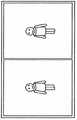
图2是用于说明安装了3D转换镜头500的状态下的数字视频摄像机100所拍摄的图像数据的示意图。FIG. 2 is a schematic diagram for explaining image data captured by the
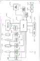
图3是表示数字视频摄像机100的构成的框图。FIG. 3 is a block diagram showing the configuration of the
图4是用于说明2D模式下的对比度AF的示意图。FIG. 4 is a schematic diagram for explaining contrast AF in 2D mode.
图5是用于说明3D模式下的对比度AF的示意图。FIG. 5 is a schematic diagram for explaining contrast AF in 3D mode.
图6是用于说明3D模式下的对比度AF控制的流程图。FIG. 6 is a flowchart for explaining contrast AF control in 3D mode.
图7是用于对摄像图像的AF评价值进行说明的示意图。FIG. 7 is a schematic diagram for explaining AF evaluation values of captured images.
具体实施方式Detailed ways
使用附图来说明将本发明应用在数字视频摄像机中的实施方式1。Embodiment 1 in which the present invention is applied to a digital video camera will be described with reference to the drawings.
[1.实施方式1][1. Embodiment 1]
[1-1.概要][1-1. Outline]
使用图1、图2来说明本实施方式1所涉及的数字视频摄像机100的概要。图1是表示在数字视频摄像机100安装了3D转换镜头500的状态下的立体图。图2是用于说明安装了3D转换镜头500的状态下的数字视频摄像机100所拍摄的图像数据的示意图。The outline of the
3D转换镜头500相对于数字视频摄像机100所具有的安装部(未图示)为可装卸。数字视频摄像机100通过检测开关(未图示)对3D转换镜头500的安装进行磁检测。The
3D转换镜头500是输出用于形成3D(three dimensions,三维)图像中的左眼用的像的光和用于形成右眼用的像的光的像输出单元。具体地,3D转换镜头500具有右眼用镜头510和左眼用镜头520。右眼用镜头510将用于形成3D图像中的右眼用的像的光导向数字视频摄像机100的光学系统。左眼用镜头520将用于形成3D图像中的左眼用的像的光导向光学系统。The
经由3D转换镜头500而入射的光在数字视频摄像机100的CCD图像传感器180上成像为图2所示那样的并排格式的3D图像。即,在数字视频摄像机100中,在安装了3D转换镜头500的状态下(3D模式)拍摄并排格式的3D图像。另外,在数字视频摄像机100中,在取下3D转换镜头500的状态下(2D模式)拍摄2D图像。The incident light through the
本实施方式1所涉及的数字视频摄像机100在这样的并排格式的3D图像中,能使对左眼用的图像和右眼用的图像的对焦偏离变小。The
[1-2.构成][1-2. Composition]
使用图3来说明本实施方式1所涉及的数字视频摄像机100的电气构成。图3是表示数字视频摄像机100的构成的框图。数字视频摄像机100用CCD图像传感器180来拍摄通过由变焦透镜110等构成的光学系统而形成的被摄体像。由CCD图像传感器180生成的影像数据被图像处理部190施加了各种处理,并贮存在存储卡240中。另外,贮存在存储卡240中的影像数据能由液晶监视器270进行显示。下面,详细说明数字视频摄像机100的构成。The electrical configuration of the
数字视频摄像机100的光学系统包含:变焦透镜110、OIS140(OpticalImage Stabilizer,光学图像稳定器)、和聚焦透镜170。聚焦透镜110能通过沿着光学系统的光轴进行移动来放大或缩小被摄体像。另外,聚焦透镜170通过沿着光学系统的光轴移动来调整被摄体像的焦点。聚焦发动机290对聚焦透镜170进行驱动。The optical system of
OIS140在内部具有能在与光轴垂直的面内移动的补正透镜。OIS140通过在抵消数字视频摄像机100的晃动的方向上驱动补正透镜来降低被摄体像的晃动。OIS140 internally has a correction lens that can move in a plane perpendicular to the optical axis. The
变焦发动机130驱动变焦透镜110。变焦发动机130可以由脉冲发动机、DC发动机、线性发动机、伺服发动机等来实现。变焦发动机130也可以经由凸轮机构或滚珠螺杆等的机构来驱动变焦透镜110。检测器120检测变焦透镜110在光轴上存在于哪个位置。检测器120根据变焦透镜110向光轴方向的移动,通过电刷等开关来输出与变焦透镜的位置相关的信号。The
OIS致动器150在与光轴垂直的面内驱动OIS140内的补正透镜。OIS致动器150能由平面线圈或超声波发动机等实现。另外,检测器160检测OIS140内的补正透镜的移动量。The OIS actuator 150 drives the correction lens in the
CCD图像传感器180对由变焦透镜110等构成的光学系统所形成的被摄体像进行拍摄,从而生成影像数据。CCD图像传感器180进行曝光、传送、电子快门等的各种动作。The
图像处理部190对由CCD图像传感器180生成的影像数据实施各种处理。图像处理部190通过对由CCD图像传感器180生成的影像数据实施处理,生成用于在液晶监视器270显示的影像数据,或生成用于贮存在存储卡240的影像数据。例如,图像处理部190对由CCD图像传感器180生成的影像数据实施伽玛补正、白平衡补正、缺陷补正等的各种处理。另外,图像处理部190对由CCD图像传感器180生成的影像数据采用依据了H.264规格或MPEG2规格的压缩格式等来压缩影像数据。图像处理部190能用DSP(Digital Signal Processor,数字信号处理器)或个人计算机等来实现。The
控制器210是控制整体的控制单元。控制器210能用半导体元件等来实现。控制器210既可以仅由硬件构成,也可以通过组合硬件和软件来实现。控制器210能用个人计算机等实现。The
存储器200作为图像处理部190以及控制器210的工作存储器而发挥功能。存储器200例如能由DRAM、强电介质存储器等实现。The
液晶监视器270能显示由CCD图像传感器180生成的影像数据所表示的图像、从存储卡240读取的影像数据所表示的图像。The liquid crystal monitor 270 can display images represented by video data generated by the
陀螺仪传感器220由压电元件等的振动材料等构成。陀螺仪传感器220通过使压电元件等的振动材料以固定频率振动,从而将基于科里奥利力的力变换为电压来得到角速度信息。通过在对来自陀螺仪传感器220的角速度信息所表示的摇晃进行抵消的方向上驱动OIS140内的补正透镜,从而数字视频摄像机100对手抖进行补正。The
卡槽230中可装卸存储卡240。卡槽230能与存储卡240进行机械式连接以及电连接。存储卡240在内部包含闪速存储器或强电介质存储器等,能贮存数据。The
内部存储器280由闪速存储器或强电介质存储器等构成。内部存储器280贮存用于控制数字视频摄像机100整体的控制程序等。The
操作部件250是受理来自使用者的操作的部件。变焦杆260是从使用者受理变焦倍率的变更指示的部件。The
另外,在本实施方式中,将光学系统110、140、170、用于驱动并控制光学系统110、140、170的各种装置120、130、150、160、290、CCD图像传感器180、图像处理部190以及存储器200定义为摄像系统300。In addition, in this embodiment,
[1-3.对比度AF(自动聚焦)][1-3. Contrast AF (Auto Focus)]
使用图4、图5来说明对比度AF。图4是用于说明2D模式下的对比度AF的示意图。图5是用于说明3D模式下的对比度AF的示意图。Contrast AF will be described using FIG. 4 and FIG. 5 . FIG. 4 is a schematic diagram for explaining contrast AF in 2D mode. FIG. 5 is a schematic diagram for explaining contrast AF in 3D mode.
首先,说明2D模式下的对比度AF。数字视频摄像机100使用摄像图像中的预先确定的区域(检波区)的图像来进行对比度AF。即,数字视频摄像机100预先决定设定检波区的范围。数字视频摄像机100在2D模式下,将摄像图像的中央部分设定为检波区。数字视频摄像机100基于检波区内的图像的亮度值来计算AF评价值(对比度值)。数字视频摄像机100控制聚焦透镜170以使得该AF评价值成为最大。这是2D模式下的对比度AF。First, contrast AF in 2D mode will be described. The
接下来,说明3D模式下的对比度AF。数字视频摄像机100在3D模式下,如图5所示,将左眼用图像的中央部分以及右眼用图像的中央部分设定为检波区。数字视频摄像机100基于各检波区的亮度值来计算左眼用图像的AF评价值(第1AF评价值)和右眼用图像AF评价值(第2AF评价值),基于各AF评价值(第1AF评价值、第2AF评价值)来计算3D图像用的AF评价值(第3AF评价值)。数字视频摄像机100基于3D图像用的AF评价值来进行对比度AF。关于3D图像用的AF评价值的计算方法,在后面叙述。另外,左眼用图像的AF评价值和右眼用图像的AF评价值采用与2D模式下的AF评价值的计算方法相同的方法计算。Next, contrast AF in 3D mode will be described. In the 3D mode of the
[1-4.3D模式下的对比度AF控制][1-4. Contrast AF control in 3D mode]
使用图6、7来说明3D模式下的对比度AF控制。图6是用于说明3D模式下的对比度AF控制的流程图。图7是用于说明摄像图像的AF评价值的示意图。Contrast AF control in 3D mode will be described using FIGS. 6 and 7 . FIG. 6 is a flowchart for explaining contrast AF control in 3D mode. FIG. 7 is a schematic diagram for explaining AF evaluation values of captured images.
通过使用者操作操作部件250,能将数字视频摄像机100设定为摄影模式(S100)。数字视频摄像机100被设定为摄影模式后,控制器210基于摄影图像(左眼用图像以及右眼用图像)来计算左眼用图像的AF评价值和右眼用图像的AF评价值(S110)。When the user operates the
在此,控制器210计算左眼用图像的AF评价值和右眼用图像的AF评价值后,控制器210计算左眼用图像的AF评价值和右眼用图像的AF评价值的积(S120)。然后,在控制器210计算左眼用图像的AF评价值和右眼用图像的AF评价值的积后,控制器210计算积的平方根(S120)。然后,控制器210将左眼用图像的AF评价值和右眼用图像的AF评价值的积的平方根的值识别为3D图像用的AF评价值。如此地计算数字视频摄像机100中的3D图像用的AF评价值。Here, after the
接下来,控制器210计算3D图像用的AF评价值后,控制器210判断3D图像用的AF评价值是否是具有可靠性的数据(S125)。在此,在与聚焦透镜170的位置变化所对应的3D图像用的AF评价值的变化量较大的情况下,判断为3D图像用的AF评价值是具有可靠性的数据。另一方面,在与聚焦透镜170的位置变化所对应的3D图像用的AF评价值的变化量较小的情况下,判断为3D图像用的AF评价值不是具有可靠性的数据。Next, after the
具体地,在S125中,控制器210判断3D图像用的AF评价值是否为规定的阈值(基准值cr)以上。基准值cr是用于判断3D图像用的AF评价值是否是具有可靠性的数据的指标。如图7所示,在3D图像用的AF评价值为基准值cr以上的范围内,由于上述的3D图像用的AF评价值的变化量成为规定值以上,因此,控制器210判断为3D图像用的AF评价值是具有可靠性的数据。另一方面,在3D图像用的AF评价值不足基准值cr的范围内,由于上述的3D图像用的AF评价值的变化量不足规定值,因此,控制器210判断为3D图像用的AF评价值是不具有可靠性的数据。Specifically, in S125, the
接下来,在3D图像用的AF评价值是具有可靠性的数据的情况下,例如,在3D图像用的AF评价值为基准值cr以上的情况下(S125:是),控制器210判断3D图像用的AF评价值的变化在时间上是否稳定(S130)。具体地,控制器210判断3D图像用的AF评价值随时间的变化是否在规定的范围内。更具体地,控制器210判断与1个视界(field)前的3D图像用的AF评价值对应的当前的视界的3D图像用的AF评价值是否不足规定值。Next, when the AF evaluation value for the 3D image is reliable data, for example, when the AF evaluation value for the 3D image is greater than or equal to the reference value cr (S125: Yes), the
在此,在3D图像用的AF评价值的变化在时间上稳定的情况下,例如,在3D图像用的AF评价值的时间变化不足规定值的情况下(S130:是),控制器210再度执行S110以后的处理。在此,3D图像用的AF评价值的变化在时间上稳定的情况与3D图像用的AF评价值为峰值附近的值的情况对应。即,这种情况下,聚焦透镜170位于与3D图像用的AF评价值的峰值对应的透镜位置附近,即后述的目标透镜位置ps的附近。Here, when the change in the AF evaluation value for 3D images is stable over time, for example, when the change over time in the AF evaluation value for 3D images is less than a predetermined value (S130: Yes), the
另外,响应于被摄体在时间上的变化,摄像图像在时间上也产生变化。由此,在S130的处理后执行S110以后的处理的情况下,响应于摄像图像在时间上的变化,在S110生成的左眼用图像的AF评价值以及右眼用图像的AF评价值发生变化。即,在S130的处理后反复执行S110以后的处理的情况下,在S120反复生成的3D图像用的AF评价值也发生变化。In addition, in response to temporal changes in the subject, captured images also change temporally. Thus, when the processing from S110 onward is executed after the processing in S130, the AF evaluation value of the left-eye image and the AF evaluation value of the right-eye image generated in S110 change in response to temporal changes in captured images. . That is, when the processing after S110 is repeatedly executed after the processing in S130 , the AF evaluation value for the 3D image repeatedly generated in S120 also changes.
另一方面,在3D图像用的AF评价值是不具有可靠性的数据的情况下(S125:否),或3D图像用的AF评价值的变化在时间上不稳定的情况下(S130:否),控制器210判断3D图像用的AF评价值是否随时间增加(S135)。具体地,控制器210判断当前视界的3D图像用的AF评价值是否大于1个视界前的3D图像用的AF评价值。On the other hand, when the AF evaluation value for the 3D image is unreliable data (S125: No), or when the change in the AF evaluation value for the 3D image is temporally unstable (S130: No ), the
在此,在3D图像用的AF评价值是不具有可靠性的数据的情况下(S125:否),由于与聚焦透镜170的位置变化对应的3D图像用的AF评价值的变化较小,因此,控制器210有时会无法决定聚焦透镜170的驱动方向。这种情况下,使聚焦透镜170在当前的行进方向上移动,直到控制器210能够决定聚焦透镜170的驱动方向为止。然后,在与聚焦透镜170的位置变化对应的3D图像用的AF评价值的变化量成为了能决定聚焦透镜170的驱动方向的值时,控制器210停止聚焦透镜170的驱动。然后,控制器210如上述那样,判断3D图像用的AF评价值是否随时间增加(S135)。Here, when the AF evaluation value for the 3D image is unreliable data (S125: No), since the change in the AF evaluation value for the 3D image corresponding to the positional change of the
接下来,在控制器210判断为3D图像用的AF评价值随时间增加的情况下(S135:是),控制器210将聚焦透镜170在当前的行进方向上驱动规定量(S136)。另一方面,在控制器210未判断出3D图像用的AF评价值随时间增加的情况下(S135:否),控制器210将聚焦透镜170在与当前的行进方向相反的方向上驱动规定量(S137)。然后,若聚焦透镜170的驱动结束,则控制器210再次执行S110以后的处理。Next, when the
这一系列的处理(S110~S137的处理)由控制器210反复执行直到摄影停止为止。This series of processing (processing of S110 to S137) is repeatedly executed by the
如此,本实施方式1所涉及数字视频摄像机100基于左眼用图像的AF评价值和右眼用图像的AF评价值来计算出3D图像用的AF评价值。下面说明如此构成的理由。In this way, the
在3D转换镜头500的左眼用镜头520和右眼用镜头510相对于摄像面没有倾斜地安装的情况下,聚焦透镜170被设置在特定的位置。由此,能使左眼用图像和右眼用图像同时对焦。详细地,在聚焦透镜170位于特定的位置的情况下,左眼用图像的AF评价值和右眼用图像的AF评价值一致。即,在这种情况下,左眼用图像的对焦位置和右眼用图像的对焦位置一致。但是,实际上,3D转换镜头500的左眼用镜头520和右眼用镜头510有可能分别相对于摄像面在微小范围内倾斜。另外,数字视频摄像机100内的光学系统也有可能相对于摄像面在微小范围内倾斜。如此,若3D转换镜头500的左眼用镜头520以及右眼用镜头510、或数字视频摄像机100中的光学系统相对于摄像面倾斜,则即使聚焦透镜170位于特定的位置,左眼用图像的AF评价值和右眼用图像的AF评价值也有可能如图7所示那样不同。即,左眼用图像的对焦位置和右眼用图像的对焦位置不同。When the left-
由此,若在该状态下基于左眼用图像的AF评价值以及右眼用图像的AF评价值中的任一AF评价值来执行对比度AF,则针对左眼用图像和右眼用图像的对焦偏离有可能会变大。其结果,在基于这些左眼用图像和右眼用图像来显示3D图像的情况下,3D图像会成为对使用者而言难以看清的图像。Therefore, if contrast AF is performed based on any one of the AF evaluation value of the left-eye image and the AF evaluation value of the right-eye image in this state, the left-eye image and the right-eye image Focus misalignment may become larger. As a result, when a 3D image is displayed based on these images for the left eye and the image for the right eye, the 3D image becomes difficult for the user to see.
因此,在本实施方式1所涉及的数字视频摄像机100中,基于左眼用图像的AF评价值和右眼用图像的AF评价值来计算能适当显示3D图像的3D图像用的AF评价值。通过使用该3D图像用的AF评价值从而针对左眼用图像和右眼用图像的对焦偏离变小,因此,在基于左眼用图像和右眼用图像来显示3D图像的情况下,3D图像成为对使用者而言容易看清的图像。Therefore, in the
下面,参照图7来详细说明3D图像用的AF评价值的评价方法。图7的横轴与聚焦透镜170所移动的光学系统的光轴对应。在图7中,用记号p1来标记聚焦透镜170的初始位置,用记号p4来标记聚焦透镜170距初始位置p1最远的位置(最大背离位置)。另外,将与左眼用图像的AF评价值的峰值对应的聚焦透镜170的透镜位置称作第1透镜位置p2,将与右眼用图像的AF评价值的峰值对应的聚焦透镜170的透镜位置称作第2透镜位置p3。进而,第1透镜位置p2和第2透镜位置p3的中间点是针对左眼用图像和右眼用图像的对焦偏离变得最小的透镜位置,将该透镜位置称作最佳透镜位置pm。Next, a method of evaluating AF evaluation values for 3D images will be described in detail with reference to FIG. 7 . The horizontal axis of FIG. 7 corresponds to the optical axis of the optical system by which the focusing
如上述那样,若左眼用镜头520和右眼用镜头510相对于摄像面倾斜,则与左眼用图像的AF评价值的峰值对应的第1透镜位置p2、和与右眼用图像的AF评价值的峰值对应的第2透镜位置p3变得不一致。若在这种状态下计算左眼用图像的AF评价值和右眼用图像的AF评价值,则如图7所示那样,很多情况下左眼用图像的AF评价值的峰值和右眼用图像的AF评价值的峰值之差的绝对值变大。As described above, if the left-
在这种情况下,若根据左眼用图像的AF评价值和右眼用图像的AF评价值之和的1/2来评价3D图像用的AF评价值,则该3D图像用的AF评价值(下面称作3D图像用的AF评价值(相加平均))会较强地受到较高一方的AF评价值(左眼用图像的AF评价值或右眼用图像的AF评价值)的影响,例如在图7中较强地受到左眼用图像的AF评价值的影响。由此,如图7所示,与3D图像用的AF评价值(相加平均)的峰值对应的透镜位置pw接近第1透镜位置p2。即,聚焦透镜170的透镜位置pw偏出最佳透镜位置pm。由此,在基于3D图像用的AF评价值(相加平均)来使聚焦透镜170向透镜位置pw移动的情况下,针对左眼用图像和右眼用图像的对焦偏离有可能会变大。另外,在图7中,用记号dw来标记聚焦透镜170的透镜位置pw和最佳透镜位置pm的距离。In this case, if the AF evaluation value for the 3D image is evaluated based on 1/2 of the sum of the AF evaluation value of the image for the left eye and the AF evaluation value of the image for the right eye, then the AF evaluation value for the 3D image (Hereafter referred to as the AF evaluation value for 3D images (additive average)) is strongly affected by the higher AF evaluation value (AF evaluation value of the left-eye image or AF evaluation value of the right-eye image) , for example in FIG. 7 is strongly influenced by the AF evaluation value of the image for the left eye. Accordingly, as shown in FIG. 7 , the lens position pw corresponding to the peak of the AF evaluation value (addition average) for 3D images approaches the first lens position p2. That is, the lens position pw of the
与此相对,在通过左眼用图像的AF评价值和右眼用图像的AF评价值的积的平方根来评价3D图像用的AF评价值的情况下,即使左眼用图像的AF评价值的峰值和右眼用图像的AF评价值的峰值之差的绝对值变大,该3D图像用的AF评价值(下面称作3D图像用的AF评价值(相乘平均))也难以较强地受到较高一方的AF评价值(左眼用图像的AF评价值或右眼用图像的AF评价值)的影响,例如在图7中,难以较强地受到左眼用图像的AF评价值的影响。In contrast, when the AF evaluation value for a 3D image is evaluated by the square root of the product of the AF evaluation value of the left-eye image and the AF evaluation value of the right-eye image, even if the AF evaluation value of the left-eye image is The absolute value of the difference between the peak value and the peak value of the AF evaluation value of the image for the right eye becomes large, and the AF evaluation value for the 3D image (hereinafter referred to as the AF evaluation value for the 3D image (multiplicative average)) is also difficult to be strong. Influenced by the higher AF evaluation value (the AF evaluation value of the left-eye image or the AF evaluation value of the right-eye image), for example, in FIG. Influence.
由此,使用了3D图像用的AF评价值(相乘平均)的情况与使用了3D图像用的AF评价值(相加平均)的情况相比,与3D图像用的AF评价值(相乘平均)的峰值对应的透镜位置ps(下面称作目标透镜位置)靠近最佳透镜位置pm。具体地,如图7所示,目标透镜位置ps与最佳透镜位置pm之间的距离ds小于透镜位置pw与最佳透镜位置pm之间的距离dw。为此,在基于3D图像用的AF评价值(相乘平均)来使聚焦透镜170的透镜位置向目标透镜位置ps移动的情况下,能使针对左眼用图像和右眼用图像的对焦偏离较小。根据这样的理由,在本实施方式1中,基于3D图像用的AF评价值(相乘平均)来设定聚焦透镜170的透镜位置。Therefore, the case where the AF evaluation value (multiplicative average) for 3D images is used is compared with the case where the AF evaluation value (multiplicative average) for 3D images is used The lens position ps (hereinafter referred to as the target lens position) corresponding to the peak of the average) is close to the optimum lens position pm. Specifically, as shown in FIG. 7 , the distance ds between the target lens position ps and the optimum lens position pm is smaller than the distance dw between the lens position pw and the optimum lens position pm. Therefore, when the lens position of the
最后,说明3D动态图像的生成时的控制以及3D静态图像的生成时的控制。另外,上述的实施方式1能够应用在3D静态图像的生成时的控制以及3D动态图像的生成时的控制双方。但是,相比于将实施方式1应用在3D静态图像中的情况,在将实施方式1应用在3D动态图像中的情况下能够更有效果地控制聚焦透镜170的驱动。下面,根据这一点,参照图7来说明聚焦透镜170的控制。Finally, control at the time of generating a 3D moving image and control at the time of generating a 3D still image will be described. In addition, the first embodiment described above can be applied to both the control at the time of generating a 3D still image and the control at the time of generating a 3D moving image. However, the drive of the
如上述那样,若左眼用镜头520和右眼用镜头510相对于摄像面倾斜,则第1透镜位置p2和第2透镜位置p3变得不一致。在此,若将聚焦透镜170设定在第1透镜位置p2以及第2透镜位置p3中的任一位置,则在右眼用图像和左眼用图像之间会产生较大的对焦偏离。即,作为3D图像成为非常难以看清的影像。为了解决该问题,非常重要的是尽量缩小针对右眼用图像和左眼用图像的对焦偏离。As described above, if the left-
例如,在3D静态图像的情况下,直到摄影按钮被按下为止,都不记录3D静态图像用的图像。由此,控制器210使聚焦透镜170沿着光学系统的光轴任意地移动直到摄影按钮被按下为止,从而能够求出右眼用图像的AF评价值的分布、和左眼用图像的AF评价值的分布。例如,在将图7解释为3D静态图像的AF评价值的图的情况下,控制器210通过使聚焦透镜170在图7的横轴的整个范围内移动来生成左眼用图像的AF评价值的分布以及右眼用图像的AF评价值的分布。For example, in the case of a 3D still image, no image for the 3D still image is recorded until the shooting button is pressed. In this way, the
于是,控制器210基于这些左眼用图像的AF评价值的分布以及右眼用图像的AF评价值的分布来检测第1透镜位置p2和第2透镜位置p3。然后,控制器210将聚焦透镜170设定在第1透镜位置p2和第2透镜位置p3之间的中间点位置、即最佳透镜位置pm。如此,在3D静态图像的情况下,能缩小针对右眼用图像和左眼用图像的对焦偏离的程度。Then, the
另一方面,在3D动态图像的情况下,将3D动态图像用的图像实时地记录为时间序列数据。由此,在3D动态图像的情况下,无法像3D静态图像的情况那样使聚焦透镜170沿着光学系统的光轴任意移动来求出左眼用图像的AF评价值的分布以及右眼用图像的AF评价值的分布。理由在于,例如在为了生成左眼用图像的AF评价值的分布以及右眼用图像的AF评价值的分布而使聚焦透镜170在光学系统的光轴的整个范围(图7的横轴的整个范围)移动的情况下,聚焦透镜170移动期间内的图像会被记录为时间序列数据,会生成不自然的3D动态图像。On the other hand, in the case of 3D video images, images for 3D video images are recorded in real time as time-series data. Therefore, in the case of a 3D moving image, unlike in the case of a 3D still image, it is impossible to arbitrarily move the
由此,在3D动态图像的情况下,未基于左眼用图像的AF评价值的分布以及右眼用图像的AF评价值的分布来检测第1透镜位置p2和第2透镜位置p3,也未将聚焦透镜170设定在最佳透镜位置pm。即,在3D动态图像的情况下,无法以与3D静态图像的情况相同的形式来控制聚焦透镜170的驱动。Thus, in the case of a 3D moving image, the first lens position p2 and the second lens position p3 are not detected based on the distribution of the AF evaluation values of the left-eye image and the distribution of the AF evaluation values of the right-eye image, nor are they detected. The focusing
因此,在此,考虑采用现有的在动态图像中使用的方法来控制聚焦透镜170对3D动态图像的控制。例如,在图7中,在聚焦透镜170位于初始位置p1和第1透镜位置p2之间的状态下使聚焦透镜170在横轴上从左向右移动的情况下,左眼用图像的AF评价值和右眼用图像的AF评价值相互增加。这种情况下,控制器210判断为聚焦透镜170正向2个AF评价值的峰值移动,使聚焦透镜170沿着当前的行进方向(图7的右方)移动。另外,在该状态下使聚焦透镜170在横轴上从右向左移动的情况下,左眼用图像的AF评价值和右眼用图像的AF评价值相互减少。这种情况下,控制器210判断为聚焦透镜170正向远离2个AF评价值的峰值的方向移动,使聚焦透镜170沿着与当前的行进方向相反的方向(图7的右方)移动。Therefore, here, it is considered to adopt the existing method used in dynamic images to control the
另外,在聚焦透镜170位于第2透镜位置p3和最大背离位置p4之间的状态下使聚焦透镜170在横轴上从左向右移动的情况下,左眼用图像的AF评价值和右眼用图像的AF评价值相互减少。这种情况下,控制器210判断为聚焦透镜170正向远离2个AF评价值的峰值的方向移动,使聚焦透镜170在与当前的行进方向相反的方向(图7的左方)上移动。另外,在该状态下使聚焦透镜170在横轴上从右向左移动的情况下,左眼用图像的AF评价值和右眼用图像的AF评价值相互增加。这种情况下,控制器210判断为聚焦透镜170正向2个AF评价值的峰值移动,使聚焦透镜170在当前的行进方向(图7的左方)上移动。In addition, when the
另一方面,在图7中,在聚焦透镜170位于第1透镜位置p2和第2透镜位置p3之间的情况下,从第1透镜位置p2向第2透镜位置p3,左眼用图像的AF评价值减少,右眼用图像的AF评价值增加。这种情况下,控制器210无法判断是应使聚焦透镜170沿着当前的行进方向移动,还是沿着与当前的移动方向相反的方向移动。即,这种情况下,控制器210变得无法决定聚焦透镜170的透镜位置。为此,现有的在动态图像中使用的方法中,无法控制针对3D动态图像进行的聚焦透镜170的驱动。On the other hand, in FIG. 7, when the
为此,在本实施方式1中,为了能解决该问题,通过控制器210来控制聚焦透镜170。例如,首先,基于左眼用图像的AF评价值以及右眼用图像的AF评价值来生成新的评价值、即3D图像用的AF评价值。具体地,如上述那样,通过计算左眼用图像的AF评价值和右眼用图像的AF评价值之积的平方根来生成3D图像用的AF评价值(相乘平均)。Therefore, in Embodiment 1, in order to solve this problem, the
接下来,控制器210基于3D图像用的AF评价值来控制聚焦透镜170的驱动。这种情况下,由于图7的横轴上的某1个透镜位置对应的3D图像用的AF评价值(某时刻的AF评价值)只存在1个,因此控制器210能够响应于3D图像用的AF评价值的增减来使聚焦透镜170移动,从而能够决定聚焦透镜170的透镜位置。Next, the
例如,在聚焦透镜170位于初始位置p1和目标透镜位置ps之间的状态下使聚焦透镜170在横轴上从左向右移动的情况下,3D图像用的AF评价值增加。这种情况下,控制器210判断为聚焦透镜170正向3D图像用的AF评价值的峰值移动,使聚焦透镜170沿着当前的行进方向(图7的右方)移动。另外,在该状态下使聚焦透镜170在横轴上从右向左移动的情况下,3D图像用的AF评价值减少。这种情况下,控制器210判断为聚焦透镜170正向远离3D图像用的AF评价值的峰值的方向移动,使聚焦透镜170沿着与当前的行进方向相反的反向(图7的右方向)移动。For example, when the
另外,在聚焦透镜170位于目标透镜位置ps和最大背离位置p4之间的状态下使聚焦透镜170从左向右移动了的情况下,由于3D图像用的AF评价值减少,因此,控制器210判断为聚焦透镜170正向远离3D图像用的AF评价值的峰值的方向移动,使聚焦透镜170沿着与当前的行进方向相反的方向(图7的左方)移动。另外,在该状态下聚焦透镜170从右向左移动的情况下,由于3D图像用的AF评价值增加,因此,控制器210判断为聚焦透镜170正向3D图像用的AF评价值的峰值移动,使聚焦透镜170沿着当前的行进方向(图7的左方)移动。In addition, when the
如此,在本实施方式1中,通过使用新的评价值、即3D图像用的AF评价值,从而能够在沿着光学系统的光轴的整个范围(图7的从初始位置p1到最大背离位置p4为止的整个范围)中正确地设定聚焦透镜170的透镜位置。另外,控制器210由于能够始终使聚焦透镜170向目标透镜位置ps移动,因此能够缩小针对右眼用图像和左眼用图像的对焦偏离。In this way, in Embodiment 1, by using a new evaluation value, that is, an AF evaluation value for 3D images, it is possible to obtain a full range along the optical axis of the optical system (from the initial position p1 to the maximum divergence position in FIG. 7 ). The lens position of the
[2.其它实施方式][2. Other Embodiments]
上面,说明了实施方式1作为本发明的实施方式。但本发明并不限定于此。为此,下面总结说明本发明的其它实施方式。In the above, Embodiment 1 has been described as an embodiment of the present invention. However, the present invention is not limited thereto. For this reason, other embodiments of the present invention are summarized below.
本实施方式所涉及的数字视频摄像机100的光学系统以及驱动系统并不限定于图3所示的构成。例如,在图3中例示了光学系统110、140、170的三组构成,但也可以是其它构成的光学系统。另外,图3所示的光学系统的各透镜110、140、170既可以由1个透镜构成,也可以构成为由多个透镜构成的透镜组。The optical system and driving system of the
另外,在实施方式1中,示出了在将3D转换镜头500安装在数字视频摄像机100的状态下拍摄3D图像的情况下的示例,但本发明并不限定于此。例如,也可以构成为将右眼用镜头510和左眼用镜头520内置于数字视频摄像机100中。这种情况下,数字视频摄像机100针对各透镜510、520来准备图3所示的摄像系统300。即在数字视频摄像机100中准备2个系统的摄像系统300。这种情况下,通过各摄像系统300来生成2个图像、即左眼用影像和右眼用图像。然后,分别对左眼用图像以及右眼用图像执行S110到S140为止的处理。如此,即使在将右眼用镜头510和左眼用镜头520内置于数字视频摄像机100的情况下,也能与实施方式1相同地实现本发明。In addition, in Embodiment 1, an example of capturing a 3D image with the
另外,在实施方式1中,作为摄像单元,例示了CCD图像传感器180,但本发明并不限定于此。例如,既可以用CMOS图像传感器构成,也可以用NMOS图像传感器构成。In addition, in Embodiment 1, the
另外,在实施方式1中,在3D模式下的对比度AF时,计算左眼用图像的AF评价值和右眼用图像的AF评价值的积,并求出平方根,将该平方根作为3D图像用的AF评价值。但是,也并不一定限于这样的构成。例如,也可以构成如下:在左眼用图像的AF评价值的峰值与右眼用图像的AF评价值的峰值之差的绝对值较小的情况下,计算左眼用图像的AF评价值和右眼用图像的AF评价值的平均值,将该平均值作为3D图像用的AF评价值。总而言之,只要基于左眼用图像的AF评价值和右眼用图像的AF评价值来计算3D图像用的AF评价值即可。Also, in Embodiment 1, at the time of contrast AF in the 3D mode, the product of the AF evaluation value of the image for the left eye and the AF evaluation value of the image for the right eye is calculated, and the square root is obtained, and the square root is used as the value for the 3D image. AF evaluation value. However, it is not necessarily limited to such a configuration. For example, a configuration may be adopted in which, when the absolute value of the difference between the peak value of the AF evaluation value of the image for the left eye and the peak value of the AF evaluation value of the image for the right eye is small, the sum of the AF evaluation value of the image for the left eye and The average value of the AF evaluation values of the images for the right eye is used as the AF evaluation value for the 3D image. In short, it is only necessary to calculate the AF evaluation value for the 3D image based on the AF evaluation value of the left-eye image and the AF evaluation value of the right-eye image.
另外,在实施方式1中,如图5所示,示出了在左眼用图像的中央部分以及右眼用图像的中央部分设定检波区的情况下的示例,但本发明并不限定于此。换言之,在左眼用图像以及右眼用图像中,不管将检波区设定在哪个范围,都能够应用本发明。In addition, in Embodiment 1, as shown in FIG. 5 , an example was shown in the case where the detection regions were set at the central portion of the image for the left eye and the central portion of the image for the right eye, but the present invention is not limited to this. In other words, the present invention can be applied to the left-eye image and the right-eye image regardless of the range in which the detection area is set.
产业上的可利用性Industrial availability
本发明能够应用在数字视频摄像机、数字静态照相机等摄像装置中。The present invention can be applied to imaging devices such as digital video cameras and digital still cameras.
符号说明Symbol Description
100 数字视频摄像机100 digital video cameras
110 变焦透镜110 zoom lens
120 检测器120 detectors
130 变焦发动机130 zoom engine
140 OIS140 OIS
150 OIS致动器150 OIS actuator
160 检测器160 detectors
170 聚焦透镜170 focus lens
180 CCD图像传感器180 CCD image sensor
190 图像处理部190 Image Processing Department
200 存储器200 memory
210 控制器210 controller
220 陀螺仪传感器220 Gyro Sensors
230 卡槽230 card slot
240 存储卡240 memory cards
250 操作部件250 operating parts
260 变焦杆260 zoom lever
270 液晶监视器270 LCD monitor
280 内部存储器280 internal memory
Claims (7)
Applications Claiming Priority (3)
| Application Number | Priority Date | Filing Date | Title |
|---|---|---|---|
| JP2010178139 | 2010-08-06 | ||
| JP2010-178139 | 2010-08-06 | ||
| PCT/JP2011/002941WO2012017585A1 (en) | 2010-08-06 | 2011-05-26 | Imaging device |
Publications (1)
| Publication Number | Publication Date |
|---|---|
| CN103069324Atrue CN103069324A (en) | 2013-04-24 |
Family
ID=45559111
Family Applications (1)
| Application Number | Title | Priority Date | Filing Date |
|---|---|---|---|
| CN2011800385371APendingCN103069324A (en) | 2010-08-06 | 2011-05-26 | Imaging device |
Country Status (4)
| Country | Link |
|---|---|
| US (1) | US20130147920A1 (en) |
| JP (1) | JPWO2012017585A1 (en) |
| CN (1) | CN103069324A (en) |
| WO (1) | WO2012017585A1 (en) |
Cited By (1)
| Publication number | Priority date | Publication date | Assignee | Title |
|---|---|---|---|---|
| CN105629442A (en)* | 2016-03-29 | 2016-06-01 | 广州市全像光学科技有限公司 | Image pickup optical lens assembly |
Families Citing this family (2)
| Publication number | Priority date | Publication date | Assignee | Title |
|---|---|---|---|---|
| JP5789793B2 (en)* | 2011-08-23 | 2015-10-07 | パナソニックIpマネジメント株式会社 | Three-dimensional imaging device, lens control device, and program |
| WO2013190814A1 (en)* | 2012-06-22 | 2013-12-27 | 株式会社ニコン | Image processing device, imaging device, and image processing program |
Citations (4)
| Publication number | Priority date | Publication date | Assignee | Title |
|---|---|---|---|---|
| JPS62169131A (en)* | 1986-01-21 | 1987-07-25 | Sony Corp | Camera |
| JPH07104400A (en)* | 1993-10-07 | 1995-04-21 | Asahi Optical Co Ltd | Stereo photography equipment |
| JP2005062729A (en)* | 2003-08-20 | 2005-03-10 | Olympus Corp | Camera |
| JP2005173270A (en)* | 2003-12-11 | 2005-06-30 | Canon Inc | Stereoscopic optical device, photographing device, stereoscopic photographing system, and stereoscopic photographing device |
Family Cites Families (5)
| Publication number | Priority date | Publication date | Assignee | Title |
|---|---|---|---|---|
| US7604348B2 (en)* | 2001-01-23 | 2009-10-20 | Kenneth Martin Jacobs | Continuous adjustable 3deeps filter spectacles for optimized 3deeps stereoscopic viewing and its control method and means |
| US8369607B2 (en)* | 2002-03-27 | 2013-02-05 | Sanyo Electric Co., Ltd. | Method and apparatus for processing three-dimensional images |
| DE602005026982D1 (en)* | 2004-11-16 | 2011-04-28 | Citizen Holdings Co Ltd | AUTOMATIC FOCUSING DEVICE |
| JP2008009342A (en)* | 2006-06-30 | 2008-01-17 | Sony Corp | Autofocus device and method, and imaging apparatus |
| JP2012027263A (en)* | 2010-07-23 | 2012-02-09 | Sony Corp | Imaging apparatus, control method and program thereof |
- 2011
- 2011-05-26CNCN2011800385371Apatent/CN103069324A/enactivePending
- 2011-05-26WOPCT/JP2011/002941patent/WO2012017585A1/enactiveApplication Filing
- 2011-05-26JPJP2012527567Apatent/JPWO2012017585A1/ennot_activeWithdrawn
- 2013
- 2013-02-05USUS13/760,001patent/US20130147920A1/ennot_activeAbandoned
Patent Citations (4)
| Publication number | Priority date | Publication date | Assignee | Title |
|---|---|---|---|---|
| JPS62169131A (en)* | 1986-01-21 | 1987-07-25 | Sony Corp | Camera |
| JPH07104400A (en)* | 1993-10-07 | 1995-04-21 | Asahi Optical Co Ltd | Stereo photography equipment |
| JP2005062729A (en)* | 2003-08-20 | 2005-03-10 | Olympus Corp | Camera |
| JP2005173270A (en)* | 2003-12-11 | 2005-06-30 | Canon Inc | Stereoscopic optical device, photographing device, stereoscopic photographing system, and stereoscopic photographing device |
Cited By (1)
| Publication number | Priority date | Publication date | Assignee | Title |
|---|---|---|---|---|
| CN105629442A (en)* | 2016-03-29 | 2016-06-01 | 广州市全像光学科技有限公司 | Image pickup optical lens assembly |
Also Published As
| Publication number | Publication date |
|---|---|
| US20130147920A1 (en) | 2013-06-13 |
| WO2012017585A1 (en) | 2012-02-09 |
| JPWO2012017585A1 (en) | 2013-09-19 |
Similar Documents
| Publication | Publication Date | Title |
|---|---|---|
| CN110012224B (en) | Camera anti-shake system, method, electronic device and computer-readable storage medium | |
| CN103748493B (en) | Camera head and its control method | |
| US9491439B2 (en) | Three-dimensional image capture device, lens control device and program | |
| US9092875B2 (en) | Motion estimation apparatus, depth estimation apparatus, and motion estimation method | |
| JP2012015999A (en) | Imaging device, image generating method, and computer program | |
| JP5597525B2 (en) | Stereoscopic imaging device and stereoscopic imaging method | |
| US20150281553A1 (en) | Image-capturing apparatus | |
| CN112995498B (en) | Image processing apparatus, image capturing apparatus, image processing method, and storage medium | |
| JP6432038B2 (en) | Imaging device | |
| JP6659100B2 (en) | Imaging device | |
| JP5688543B2 (en) | Stereoscopic imaging device and lens driving method in stereoscopic imaging device | |
| JP6136019B2 (en) | Moving image photographing apparatus and focusing method of moving image photographing apparatus | |
| TW201935912A (en) | Image processing method, electronic device, and non-transitory computer readable storage medium | |
| US20160275657A1 (en) | Imaging apparatus, image processing apparatus and method of processing image | |
| CN103069324A (en) | Imaging device | |
| US20140104485A1 (en) | Imaging apparatus | |
| WO2013069279A1 (en) | Image capturing device | |
| US20130076867A1 (en) | Imaging apparatus | |
| KR20130047343A (en) | Camera module and method for obtaining three-dimensional photographic image of the same | |
| US8786677B2 (en) | Imaging device | |
| US20120033050A1 (en) | Imaging apparatus | |
| JP2021033233A (en) | Image blur correction device and control method thereof, program, and imaging apparatus including image blur correction device | |
| JP2015102602A (en) | Stereoscopic imaging device, stereoscopic imaging system, control method of stereoscopic imaging device, program, and storage medium | |
| JP2013179580A (en) | Imaging apparatus | |
| JPWO2012017596A1 (en) | Imaging device |
Legal Events
| Date | Code | Title | Description |
|---|---|---|---|
| C06 | Publication | ||
| PB01 | Publication | ||
| C10 | Entry into substantive examination | ||
| SE01 | Entry into force of request for substantive examination | ||
| C02 | Deemed withdrawal of patent application after publication (patent law 2001) | ||
| WD01 | Invention patent application deemed withdrawn after publication | Application publication date:20130424 |